spac 315 c and spac 317 c feeder terminals · 2018-05-10 · 6 the feeder terminals type spac 315 c...
TRANSCRIPT
IRF2
5
RS 615 Ser.No. SPTO 1D6
O I
Uaux
30 ... 80 V _80 ... 265 V _
R
L
SG1
12
0 1
I
STEP
I
I
L1
L2
L3
[kA]
[kA]
[kA]
O
I
TEST
INTERLOCK
[MW]
[Mvar]
[GWh, MWh, kWh]
P
Q
E
RS 232
GAS PRESSURE
MOTOR VOLTAGE
fn = 50 60 Hz SPAC 315 CnI = /1 5 A( )oInI = /1 5 A( )I
[
SGR
SGB
SGF
SPCJ 4D29
TRIP
PROGRAM
RESETSTEP
L1 L2 L3 o IRF
3 >II
IIII
> nI I/
ks>t ]
n>>I I/
s>>[ ]t
so >ko
[ ]t
no >I I/
s>>ot [ ]
n>>o I/I
0012
A
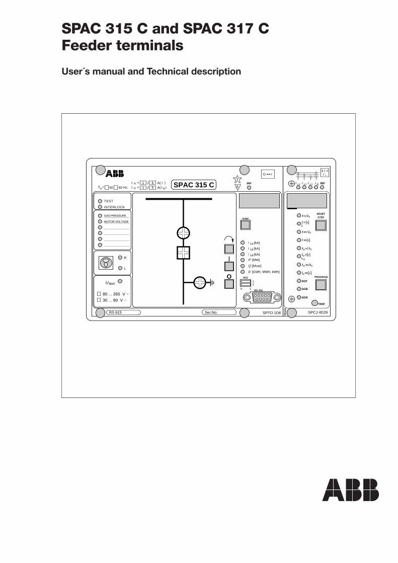
SPAC 315 C and SPAC 317 CFeeder terminals
User´s manual and Technical description
2
1MRS 750117-MUM EN
Issued 1995-05-22Modified 2002-05-17Version BChecked MKApproved OL
Data subject to change without notice
SPAC 315 CSPAC 317 C
Feeder terminals
Features .......................................................................................................................... 3Area of application .......................................................................................................... 4Description of function .................................................................................................. 6
Design ....................................................................................................................... 6Protection functions .................................................................................................. 8Control functions ...................................................................................................... 9Measurement functions ........................................................................................... 10Supervision functions .............................................................................................. 10Serial communication .............................................................................................. 10Auxiliary power supply ............................................................................................ 10
Application ................................................................................................................... 11Mounting and dimension drawings ......................................................................... 11Connection diagram ................................................................................................ 12Signal diagram ......................................................................................................... 16Terminals and wiring .............................................................................................. 18
Commissioning ............................................................................................................ 19Technical data (modified 2002-05) ............................................................................... 20Exchange and spare parts .............................................................................................. 24Maintenance and repairs ............................................................................................... 24Order information ........................................................................................................ 25
The user's manual for the feeder terminals SPAC 315 C and SPAC 317 C is composed of thefollowing separate manuals:
Feeder terminal SPAC 315 C and SPAC 317 C, general part 1MRS 750117-MUM ENControl module SPTO 1D6 1MRS 750118-MUM ENGeneral characteristics of D type relay modules 1MRS 750066-MUM ENCombined overcurrent and earth-fault relay module SPCJ 4D29 1MRS 750119-MUM EN
Contents
3
Features Complete feeder terminal with a three-phasetwo-stage overcurrent unit and a two-stage non-directional earth-fault unit
Definite time or inverse definite minimum time(IDMT) operation characteristic for the low-setstage of the overcurrent unit and the earth-faultunit
Instantaneous or definite time operation char-acteristic of the high-set stage of the overcurrentunit and the earth-fault unit
Continuous monitoring of energizing inputcurrent circuits
Continuous circuit breaker trip circuit supervi-sion
User-configurable feeder level interlocking sys-tem for preventing unpermitted switching op-erations
Local and remote status indication of threeswitching objects
Complete control module for local/remote con-trol of one switching object
Double-pole circuit-breaker control for addi-tional operational safety
Large library of pre-designed mimic diagramplates for presentation of the selected circuit-breaker/disconnector configuration
Phase current, energy, active and reactive powermeasurement and indication
Serial interface for connection of the feederterminal to a substation level and networkcontrol level systems
Continuous self-supervision for maximum sys-tem reliability and availability.
4
OPTICAL SPA-BUS
SUBSTATION LEVEL DATA COMMUNICATOR
CONNECTION TO NETWORK CONTROL LEVEL
FEEDER TERMINAL FEEDER TERMINAL FEEDER TERMINAL
FEEDER TERMINAL
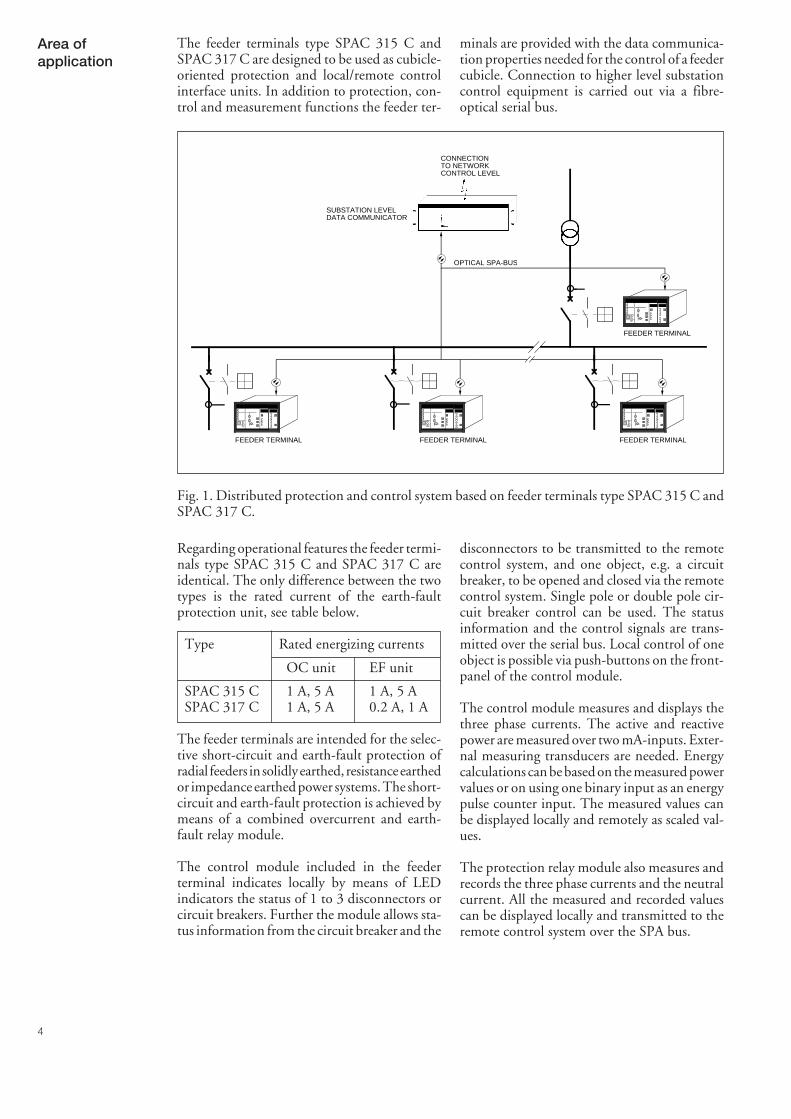
The feeder terminals type SPAC 315 C andSPAC 317 C are designed to be used as cubicle-oriented protection and local/remote controlinterface units. In addition to protection, con-trol and measurement functions the feeder ter-
minals are provided with the data communica-tion properties needed for the control of a feedercubicle. Connection to higher level substationcontrol equipment is carried out via a fibre-optical serial bus.
Fig. 1. Distributed protection and control system based on feeder terminals type SPAC 315 C andSPAC 317 C.
Regarding operational features the feeder termi-nals type SPAC 315 C and SPAC 317 C areidentical. The only difference between the twotypes is the rated current of the earth-faultprotection unit, see table below.
Type Rated energizing currents
OC unit EF unit
SPAC 315 C 1 A, 5 A 1 A, 5 ASPAC 317 C 1 A, 5 A 0.2 A, 1 A
The feeder terminals are intended for the selec-tive short-circuit and earth-fault protection ofradial feeders in solidly earthed, resistance earthedor impedance earthed power systems. The short-circuit and earth-fault protection is achieved bymeans of a combined overcurrent and earth-fault relay module.
The control module included in the feederterminal indicates locally by means of LEDindicators the status of 1 to 3 disconnectors orcircuit breakers. Further the module allows sta-tus information from the circuit breaker and the
disconnectors to be transmitted to the remotecontrol system, and one object, e.g. a circuitbreaker, to be opened and closed via the remotecontrol system. Single pole or double pole cir-cuit breaker control can be used. The statusinformation and the control signals are trans-mitted over the serial bus. Local control of oneobject is possible via push-buttons on the front-panel of the control module.
The control module measures and displays thethree phase currents. The active and reactivepower are measured over two mA-inputs. Exter-nal measuring transducers are needed. Energycalculations can be based on the measured powervalues or on using one binary input as an energypulse counter input. The measured values canbe displayed locally and remotely as scaled val-ues.
The protection relay module also measures andrecords the three phase currents and the neutralcurrent. All the measured and recorded valuescan be displayed locally and transmitted to theremote control system over the SPA bus.
Area ofapplication
5
PROTECTION
- PHASE OVERCURRENT- EARTH-FAULT
MEASUREMENT
- PHASE CURRENTS- RESIDUAL CURRENT- ACTIVE AND REACTIVE POWER- ENERGY
SUPERVISION
- TRIP CIRCUIT- INPUT CURRENT MONITORING
CONTROL
- CB AND DISCONNECTOR STATUS- CB LOCAL AND REMOTE CONTROL- DOUBLE/SINGLE POLE OPERATION - MIMIC DISPLAY- BLOCKINGS
Ι
O
O <-> I READY
SIGNALLING
SERIALBUS
SPAC 315 C
IL1 / IL2 / IL3
Io
IPQE
3I>
I >
3∆I/IN
TCS
Fig. 2. Basic functions of the feeder terminals type SPAC 315 C and SPAC 317 C.
6
The feeder terminals type SPAC 315 C andSPAC 317 C include four withdrawable func-tional modules and one fixed functional module
each. The main functions of the modules arespecified in the following table.
Module Function
Protection relay module Phase overcurrent protection and earth-fault protection.SPCJ 4D29 Definite time or inverse time low-set overcurrent and earth-
fault protection, instantaneous or definite time high-set over-current and earth-fault protection.
Control module SPTO 1D6 Reads and displays locally and remotely status data of maxi-mum three disconnectors, CB trucks or CBs.Reads and displays locally and remotely max. six externalbinary signals.Three phase currents, active and reactive power and energyare measured and displayed locally and remotely.Transfers local or remote open and close commands for onecircuit breaker.
I/O module SPTR 2B17 or Includes 12 optically isolated binary inputs, trip and closeSPTR 2B18 output relays. Single-pole or double-pole circuit breaker
control and trip circuit supervision electronics.
Power supply module Forms the internal sypply voltages required by the otherSPGU 240A1 or SPGU 48B2 function modules.
Energizing input module Includes matching transformers and their tuning electronicsSPTE 4F6 in SPAC 315 C or for three phase currents and the neutral current.SPTE 4F9 in SPAC 317 C Includes the motherboard with four signalling output con-
tacts and the electronics for the mA inputs.Includes the Internal Relay Fault alarm output relay.
The combined phase overcurrent and earth-fault relay module SPCJ 4D29 is a Euro-size(100 mm x 160 mm) withdrawable unit.
The control module type SPTO 1D6 is alsowithdrawable. The control module includes twoPC boards; a CPU board and a front PC boardwhich are joined together.
The I/O module SPTR 2B_ is located behindthe front PC board and is fixed to the front PCboard by screws.
The power supply module SPGU 240A1 orSPGU 48B2 is located behind the front PCboard of the control module and can be with-drawn from the case after the control modulehas been removed.
The protection relay module SPCJ 4D29 isfastened to the relay case by means of two fingerscrews and the control module type SPTO 1D6by means of four finger screws.
These modules are removed by undoing thefinger screws and pulling the modules out of thealuminium case. Before the I/O module can beremoved the control module has to be with-drawn from the case and the screws holding theI/O module attached to the front PC board haveto be removed.
The energizing input module SPTE 4F6 orSPTE 4F9 is located behind the front PC boardof the control module on the left side of the case.A screw terminal block, the rear plate and themother PC board are connected to the energiz-ing input module.
The mother PC board contains the card connec-tors for the plug-in modules, the detachablemulti-pole connector strips of the inputs andoutputs, the tuning resistors of the secondaryburden of the matching transformers and theelectronics of the signal outputs and mA inputs.
Description offunction
Design
7
Fig. 3. Block diagram for the feeder terminals type SPAC 315 C and SPAC 317 C
U1 Phase overcurrent and earth-fault relay module SPCJ 4D29U2 Control module SPTO 1D6U3 I/O module SPTR 2B17 or SPTR 2B18 for digital inputs and contact outputsU4 Power supply module SPGU 240A1 or SPGU 48B2U5 Energizing input module and motherboard SPTE 4F6 or SPTE 4F9X0 Screw terminal stripX1…X3 Multi-pole connector stripsRx/Tx Serial communication port
The relay case is made of an extruded alumin-ium section, the collar is of cast aluminium andthe cover of clear UV-stabilized polycarbonate.The collar is fitted with a rubber gasket provid-ing an IP54 degree of protection by enclosurebetween the relay case and the mounting panel.
The cover of the case contains two push-buttonswhich can be used for scanning through thedisplays of the feeder terminal. To reset the
operation indicators of the protection and touse the local control push-buttons of the controlmodule, the front cover has to be opened.
The cover is locked with two finger screwswhich can be sealed to prevent unauthorizedaccess to the front panel. The rubber gasketbetween the cover and the collar ensures that thecover, too, complies with the IP54 require-ments. The opening angle of the cover is 145°.
Rx/TxX3X1X0 X2
O <-> I I P Q E
U2 U1U3U4U5
Io>Io >>
3I >3I>>
3∆I/IN TCF
8
The overcurrent unit of the combined overcur-rent and earth-fault relay module SPCJ 4D29has two operation stages, a low-set stage I> anda high-set stage I>>. The overcurrent unit meas-ures the three phase currents of the protectedsystem. The unit can also be used for two orsingle phase measurement.
When a phase current exceeds the set start valueof the low-set overcurrent stage, the overcurrentstage starts, simultaneously starting the corre-sponding timing circuit. When the set or calcu-lated operate time has elapsed, a trip commandis delivered. Correspondingly the high-set over-current stage starts when its start value is ex-ceeded. As the high-set stage starts it starts itstiming circuit and trips when the set operatetime has elapsed.
The low-set stage of the overcurrent unit can begiven definite time characteristic or inverse defi-
nite minimum time (IDMT) characteristic. Thehigh-set stage of the overcurrent unit can be setto operate instantaneously or it can be givendefinite time characteristic.
By appropriate configuration of the output relaymatrix the start signals can be obtained as con-tact functions. The start signals can be used, forinstance, as blocking signals for cooperatingprotection relays.
The combined overcurrent and earth-fault relaymodule contains one external control input,which is activated by an external control voltageapplied to the input CHANNEL 8. The influ-ence of the external blocking signal on the relaymodule is determined by the selector switches ofthe relay module. The control input can be usedfor blocking one or more of the protection stagesor for carrying out a trip command by means ofan external control signal.
The combined overcurrent and earth-fault relaymodule SPCJ 4D29 also includes a non-direc-tional two-stage earth-fault protection unit. Theearth-fault unit measures the residual current orneutral current of the protected system.
When the residual current exceeds the set startvalue of the low-set earth-fault stage, the earth-fault stage starts, simultaneously starting thecorresponding timing circuit. When the set orcalculated operate time has elapsed, a trip com-mand is delivered. Correspondingly the high-set earth-fault stage starts when its start value isexceeded. As the high-set stage starts it stars its
timing circuit and trips when the set operatetime has elapsed.
The low-set stage of the earth-fault unit may begiven definite time characteristic or inverse defi-nite minimum time (IDMT) characteristic. Thehigh-set stage of the earth-fault unit operateswith definite time characteristic.
The operation of the two earth-fault stages canbe blocked by feeding a control voltage to theexternal control input CHANNEL 8 of thefeeder terminal.
The tripping signal of the feeder terminal iswired to the OPEN output. Double-pole orsingle-pole circuit breaker control can be usedfor opening and closing of the circuit breaker.Single-pole circuit breaker control is used asstandard. If double-pole circuit breaker controlis to be used the interconnections of terminals96-97 of the OPEN circuit and terminals 98-99of the CLOSE circuit shoud be removed, see
Fig. 5.2. The trip OPEN circuit is continuouslysupervised by means of the constant currentinjection principle. The feeder terminal has fivesignalling contacts, one of which is the commoninternal relay failure (IRF) output. Four signal-ling outputs, SIGNAL 1…4, can be used toindicate starting or tripping of the protection,see chapter "Signal diagram".
Protectionfunctions
Phase overcurrentprotection
Earth-fault protection
Contact outputs ofthe protection
9
The control module SPTO 1D6 is used forreading status information from circuit break-ers, CB trucks and disconnectors.The moduleindicates the status locally by means of LEDindicators and transfers the information to thesubstation level via the optical-fibre SPA bus.The status of maximum three objects can beindicated.
The control module is also used for controllingone object e.g. a circuit breaker, locally by means
of push-buttons on the front panel or with theopening or closing commands received over theSPA bus. Normally the double-pole controlprinciple is used for controlling the circuitbreaker.
In addition to status information the controlmodule can read other binary data, indicate theinformation locally and transfer it to the substa-tion level equipment. Six external binary signalscan be wired to the feeder terminal.
The control module uses input channels 1…3to read status information from circuit breakers,CB trucks and disconnectors. Each inputCHANNEL 1…3 is formed by two binaryinputs, one input is used for reading the openstatus and the other for reading the close statusof an object. This means that the status informa-tion must be wired to the feeder terminal asfour-pole message.
The front panel of the control module holds a4x4 LED matrix, which is used for status indi-cation of the circuit-breakers, CB trucks anddisconnectors of the feeder cubicle. At a time,three of these LEDs can be used for statusindication. The circuit breaker/CB truck/disconnector configuration indicated by theLEDs is freely configurable by the user.
One of the objects, the status of which is read viainputs CHANNEL 1…3 can be controlled withthe OPEN and CLOSE outputs.
The control module can be used for reading sixexternal and four internal binary signals. Theexternal signals, CHANNEL 4…9, can be sin-gle contact data wired from the switchgear cubi-cle and the internal signals, CHANNEL 10…13,are start and trip signals of the protection relaymodule.
The inputs CHANNEL 4…13 can be confi-gured to be active at high state, i.e. input ener-gized, or active at low state, i.e. input notenergized.
The front panel has a local LED indication forthe external inputs CHANNEL 4…9. The redLED is normally lit when the input is active.
The inputs CHANNEL 4…13 can be used tocontrol the outputs OPEN, CLOSE and SIG-NAL 1…4. On activation of an input theconfigured OPEN or CLOSE output providesan output pulse, whereas the outputs SIG-NAL1…4 are continuously activated as long asthe concerned inputs are activated.
The control module includes a cubicle-orientedinterlocking which is freely programmable bythe user. By writing an interlocking program theuser defines under which circumstances thecontrolled object can be closed or opened. Whenan opening or closing command is given theinterlocking program is checked and after thatthe command is executed or canceled.
The interlocking can be so programmed that itconsiders the status of the four-pole inputsCHANNEL 1…3 and the inputs CHANNEL4…13. The trip signals of the protection relaymodule are not influenced by the interlocking.
To simplify commissioning the feeder terminalis provided with default interlocking schemes. Acertain default interlocking scheme is alwaysrelated to a certain circuit breaker/disconnectorconfiguration.
Normally the OPEN and CLOSE outputs arecontrolled by an open or close command givenby the operator. In the conditional direct outputcontrol outputs OPEN, CLOSE and SIGNAL1…4, can be controlled without an open or
close command given by the operator. In thiscase the outputs are controlled by the directoutput control program, which checks the sta-tus of the inputs CHANNEL 1…3, CHAN-NEL 4…13 and the R/L-key switch.
Control functions
General
Inputs CHANNEL1…3
Inputs CHANNEL4…9 andCHANNEL 10…13
Interlocking
Conditional directoutput control
10
The control module SPTO 1D6 and the com-bined overcurrent and earth-fault relay moduleSPCJ 4D29 both measure analog signals.
The combined overcurrent and earth-fault relaymodule measures three phase currents and theneutral current. The module displays the cur-rent values locally and transmits the informa-tion via the SPA bus to the remote controlsystem. The protection relay module displaysthe measured values as multiples of the ratedcurrent of the used energizing input of thefeeder terminal.
The control module SPTO 1D6 measures fiveanalog signals; three phase currents, active andreactive power. The transforming ratio of theprimary current transformers can be keyed in tothe control module. In that way it is possible to
display the measured phase currents as primaryvalues.
The control module measures the active andreactive power via two mA inputs. Externalmeasuring transducers are to be utilized. ThemA signals are scaled to actual MW and Mvarvalues and the data is displayed locally and canbe transmitted to the remote control system.
Active energy is measured in two ways; either bycalculating the value from the measured powervalues or by using input CHANNEL 7 as a pulsecounter input. In the latter case an externalenergy meter with pulse output will be needed.In both cases the energy measurement value isdisplayed locally and can be transmitted to theremote control system.
Energizing current circuit monitoring and tripcircuit supervision are integrated into the con-trol module SPTO 1D6. The trip circuit, i.e. theOPEN circuit, is supervised using the constantcurrent injection principle. If the resistance ofthe trip circuit exceeds a preset level, because ofloose contacts, oxidation or circuit discontinu-
ity, an alarms signal is provided via outputSIGNAL 4.
The energizing current circuit monitoring func-tion monitors the input energizing currents andprovides an alarm signal if one or two of thephase currents are interrupted.
The feeder terminal includes two serial commu-nication ports, one on the front panel and theother on the rear panel.
The 9-pin RS 232 connection on the front panelis to be used for configuring the feeder terminaland determining the circuit breaker/CB truck/disconnector configuration, for loading the
feeder-oriented interlocking program and otherdata from a terminal or a PC.
The 9-pin RS 485 connection on the rear panelconnects the feeder terminal to the SPA bus. Anoptional bus connection module type SPA-ZC17 or SPA-ZC 21 is required.
For the operation of the feeder terminal asecured auxiliary voltage supply is needed. Thepower supply module SPGU240A1 or SPGU48B2 forms the voltages required by the protec-tion relay module, the control module and theinput/ output module.
The power supply module is a transformer con-nected, i.e. galvanically isolated primary andsecondary side, flyback-type dc/dc converter.The primary side of the power supply module is
protected with a slow 1 A fuse, F1, located onthe PC board of the control module.
A green LED indicator Uaux on the front panelis lit when the power supply module is in opera-tion. There are two versions of power supplymodules available. The secondary sides are iden-tical, only the input voltage range is different.The input voltage range is indicated on the frontpanel of the control module.
Measurementfunctions
Supervisionfunctions
Serialcommunication
Auxiliary powersupply
11
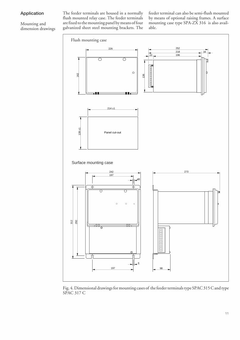
The feeder terminals are housed in a normallyflush mounted relay case. The feeder terminalsare fixed to the mounting panel by means of fourgalvanized sheet steel mounting brackets. The
feeder terminal can also be semi-flush mountedby means of optional raising frames. A surfacemounting case type SPA-ZX 316 is also avail-able.
Flush mounting case
226
162
136
196
252218
22
Panel cut-out
214 ±1
139
±1
34
Surface mounting case
197
292
273
312
242
197 98
6
ø6
Fig. 4. Dimensional drawings for mounting cases of the feeder terminals type SPAC 315 C and typeSPAC 317 C
Application
Mounting anddimension drawings
12
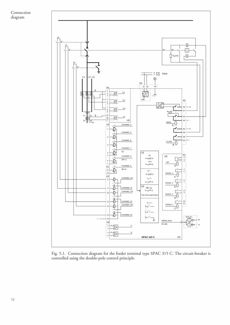
Fig. 5.1. Connection diagram for the feeder terminal type SPAC 315 C. The circuit-breaker iscontrolled using the double-pole control principle.
X1
CHANNEL 8
(BS 1)
63
I
O
5A1A
123
5A1A
4
56
5A
1A
789
5A
1A
252627
IL1
IL2
IL3
Io
X0
X2
61 62
( )( )
SPAC 315 C
L1 L2 L3
P1
P2
S1
S2
Uaux
CHANNEL 7
(E)
CHANNEL 6
CHANNEL 4
CHANNEL 5
CHANNEL 9
(BS 2)
IRF
X0
CHANNEL 3/I
CHANNEL 3/O
CHANNEL 2/I
CHANNEL 2/O
CHANNEL 1/I
CHANNEL 1/O
X3P
Q
U4
U5
U3
+ -
+
-
+
-
1
2
3
4
5
6
7
X2
12
13
8
9
10
11
12
13
14
1
2
3
4
312
Rx
Tx
SPA-ZC_
SERIAL BUS,
RS 485
F
C
66
97
X0
86
99
X1
SIGNAL 2
SIGNAL 3
SIGNAL 1
45
67
89
E
D
98
85
G
1011
SIGNAL 4
3I>
3I>>
I >>
I >
O
I
O
I
O
I
O <-> I
U1
U2
Trip circuit supervision
U5
∆I / IN
Rh(ext)
R>
AOPEN
CLOSE
B
hR (int)
3
96
65 -
-
Connectiondiagram
13
Fig. 5.2. Connection diagram for the feeder terminal type SPAC 317 C. The circuit-breaker iscontrolled using the single-pole control principle.
links are furnished at the factory. For trip circuitsupervision the proper polarity of the OPENcontact is important.
* Note!The single-pole circuit breaker control principlerequires external linking of the terminals to bedone, i.e. terminal 96 should be linked to termi-nal 97 and terminal 98 to terminal 99. These
X1
CHANNEL 8
(BS 1)
63
5A1A
123
5A1A
4
56
5A
1A
789
1A
0.2A
252627
IL1
IL2
IL3
Io
X0
X2
61 62
( )( )
SPAC 317 C
L1 L2 L3
P1
P2
S1
S2
Uaux
CHANNEL 7
(E)
CHANNEL 6
CHANNEL 4
CHANNEL 5
CHANNEL 9
(BS 2)
IRF
X0
CHANNEL 3/I
CHANNEL 3/O
CHANNEL 2/I
CHANNEL 2/O
CHANNEL 1/I
CHANNEL 1/O
X3P
Q
U4
U5
U3
+ -
+
-
+
-
1
2
3
4
5
6
7
X2
12
13
8
9
10
11
12
13
14
1
2
3
4
312
Rx
Tx
SPA-ZC_
SERIAL BUS,
RS 485
F
C
66
97
X0
86
99
X1
SIGNAL 2
SIGNAL 3
SIGNAL 1
45
67
89
E
D
98
85
G
1011
SIGNAL 4
3I>
3I>>
I >>
I >
O
I
O
I
O
I
O <-> I
U1
U2
Trip circuit supervision
U5
∆I / IN
R>
AOPEN
CLOSE
B
hR (int)
3
96
65
*
*
I
O -
-R h(ext)
14
Terminal numbers:
Terminal Terminal Functionblock number
X0 1-2 Phase current IL1, 5 A1-3 Phase current IL1, 1 A4-5 Phase current IL2, 5 A4-6 Phase current IL2, 1 A7-8 Phase current IL3, 5 A7-9 Phase current IL3, 1 A
25-26 Neutral current I0, 5 A in SPAC 315 C and 1 A in SPAC 317 C25-27 Neutral current I0, 1 A in SPAC 315 C and 0.2 A in SPAC 317 C61-62 Auxiliary power supply. When dc supply voltage is used the posi-
tive pole is to be connected to terminal 6163 Equipment earth terminal65 OPEN output
Single-pole control: terminal 65 connects to CB OPEN coilDouble-pole control: terminal 65 connects to negative controlvoltage pole
66 OPEN outputDouble/Single-pole control: terminal 66 connects to positivecontrol voltage pole
96 OPEN outputSingle-pole control: terminal 96 connects to terminal 97Double-pole control: terminal 96 connects to CB OPEN coil
97 OPEN outputSingle-pole control: terminal 97 connects to terminal 96Double-pole control: terminal 97 connects to CB OPEN coil
85 CLOSE outputSingle-pole control: terminal 85 connects to CB CLOSE coilDouble-pole control: terminal 85 connects to negative controlvoltage pole
86 CLOSE outputDouble/Single-pole control: terminal 86 connects to positivecontrol voltage pole
98 CLOSE outputSingle-pole control: terminal 98 connects to terminal 99Double-pole control: terminal 96 connects to CB CLOSE coil
99 CLOSE outputSingle-pole control: term. 99 connects to terminal 98Double-pole control: term. 99 connects to CB CLOSE coil
X1 1-2-3 Self-supervision (IRF) signalling output. When auxiliary power isconnected and the device is operating properly the interval 2-3is closed
4-5 Signal output 4. E.g.alarm from energizing current monitoring andtrip circuit supervision or 3I> alarm or 3I>> alarm or I0> alarm orI0>> alarm, configured by user
6-7 Signal output 3, configured by user8-9 Signal output 2, configured by user
10-11 Signal output 1, configured by user12-13 Input CHANNEL 9
15
Terminal numbers:
Terminal Terminal Functionblock number
X2 1-5 Input CHANNEL 42-5 Input CHANNEL 53-5 Input CHANNEL 64-5 Input CHANNEL 7 or energy pulse counter input6-7 Input CHANNEL 8 or blocking input for the protection module
8-14 Input CHANNEL 1, open status. E.g. when a circuit breaker is openthe input must be energized
9-14 Input CHANNEL 1, closed status. E.g. when a circuit breaker isclosed the input must be energized
10-14 Input CHANNEL 2, open status11-14 Input CHANNEL 2, closed status12-14 Input CHANNEL 3, open status13-14 Input CHANNEL 3, closed status
X3 1-2 mA input for the measurement of active power3-4 mA input for the measurement of reactive power
The channel numbers mentioned above areused when the control module SPTO 1D6 is tobe configured. When the control module is
configured the following codes are used for theoutputs:
Output Terminal numbers Output code Output code for Conditionalfor interlocking Output Control
OPEN X0/66-97 20 220OPEN X0/65-96 20 220CLOSE X0/86-99 21 221CLOSE X0/85-98 21 221SIGNAL 1 X1/10-11 22 22SIGNAL 2 X1/8-9 23 23SIGNAL 3 X1/6-7 24 24SIGNAL 4 X1/4-5 25 25
16
input and output signals can be configured toobtain the required functions for the feederterminal.
The initial factory settings of the feeder terminalmay have to be changed in different applica-tions. The following diagram illustrates how the
SIG
NA
L 3
(24)
SIG
NA
L 2
(23)
SIG
NA
L 1
(22)
CLO
SE
(21
)
OP
EN
(20
)
(AR
2)
(AR
1)
(AR
3)
O <
-> I
E13 12 11 10 4.
..9
1...3
IRF
OP
EN
SS
1
TS
1
TS
2
SS
3
SS
2
IRF
CH
AN
NE
LS4.
..9
6
11
CH
AN
NE
LS1.
..3
6
IL1
IL2
Io
P
Q
SPTR 2B1_SPTE 4F_
SP
TO
1D
6
IL3
1 AD
C
SIG
NA
L 1
SIG
NA
L 21
1
SPTE 4F_
1 ES
IGN
AL
3
1 F
SIG
NA
L 4
B
CLO
SE
G
IRF
&
I P Q E
SIG
NA
L 4
(25)
SG
R3
/ 1S
GR
1 / 1
SG
R3
/ 2S
GR
2 / 1
SG
R2
/ 2S
GR
1 / 2
SG
R3
/ 3S
GR
1 / 3
SG
R3
/ 4S
GR
2 / 3
SG
R2
/ 4S
GR
1 / 4
SG
R3
/ 5S
GR
1 / 5
SG
R3
/ 6S
GR
2 / 5
SG
R2
/ 6S
GR
1 / 6
SG
R3
/ 7S
GR
1 / 7
SG
R3
/ 8S
GR
2 / 7
SG
R2
/ 8S
GR
1 / 8
I> I»t»t>
, k
to>
, ko
Io>
to»
Io»
SG
B /
1
SG
B /
2
SG
B /
3
SG
B /
4S
GB
/ 5
SG
B /
8R
EM
OT
E S
ET
TIN
GS
RE
LAY
RE
SE
T
1
SG
B /
6
RE
SE
T+
PR
OG
RA
M
1
SG
B /
7
RE
SE
T+
PR
OG
RA
M
1
1
1
SG
F1
/ 4
SP
CJ
4D29
RE
SE
TT
RIP
t
SG
F2
/ 8
SG
F2
/ 7
BS
Fig. 6. Control signals between the modules of the feeder terminals type SPAC 315 C and typeSPAC 317 C
Signal diagram
17
The following table gives the default values of the switches shown in Fig. 6.
Switch Function Defaultvalue
SGB1/1 Forms from a control voltage applied to input 8 a blocking signal forthe tripping of the I> stage 0
SGB1/2 Forms from a control voltage applied to input 8 a blocking signal forthe tripping of the I>> stage 0
SGB1/3 Forms from a control voltage applied to input 8 a blocking signal forthe tripping of the I0> stage 0
SGB1/4 Forms from a control voltage applied to input 8 a blocking signal forthe tripping of the I0>> stage 0
SGB1/5 Enables switching from protection main settings to second settings byapplying an external control voltage to input 8 0
SGB1/6 Selects a latching function for the trip signal TS2 at overcurrent faults 0SGB1/7 Selects a latching function for the trip signal TS2 at earth-faults 0SGB1/8 Enables remote resetting of latched output relays and re-corded values
by an external control voltage on input 8 0
SGR1/1 Routes the start signal of stage I> to the SIGNAL 1 output 1SGR1/2 Routes the trip signal of stage I> to the OPEN output 1SGR1/3 Routes the start signal of stage I>> to the SIGNAL 1 output 0SGR1/4 Routes the trip signal of stage I>> to the OPEN output 1SGR1/5 Routes the start signal of stage I0> to the SIGNAL 1 output 0SGR1/6 Routes the trip signal of stage I0> to the OPEN output 1SGR1/7 Routes the start signal of stage I0>> to the SIGNAL 1 output 0SGR1/8 Routes the trip signal of stage I0>> to the OPEN output 1
SGR2/1 Routes the trip signal of stage I> to the SIGNAL 3 output 1SGR2/2 Routes the trip signal of stage I> to the SIGNAL 4 output 0SGR2/3 Routes the trip signal of stage I>> to the SIGNAL 3 output 1SGR2/4 Routes the trip signal of stage I>> to the SIGNAL 4 output 0SGR2/5 Routes the trip signal of stage I0> to the SIGNAL 3 output 0SGR2/6 Routes the trip signal of stage I0> to the SIGNAL 4 output 1SGR2/7 Routes the trip signal of stage I0>> to the SIGNAL 3 output 0SGR2/8 Routes the trip signal of stage I0>> to the SIGNAL 4 output 1
SGR3/1 Routes the start signal of stage I> to the SIGNAL 2 output 0SGR3/2 Routes the trip signal of stage I> to the SIGNAL 2 output 0SGR3/3 Routes the start signal of stage I>> to the SIGNAL 2 output 0SGR3/4 Routes the trip signal of stage I>> to the SIGNAL 2 output 0SGR3/5 Routes the start signal of stage I0> to the SIGNAL 2 output 0SGR3/6 Routes the trip signal of stage I0> to the SIGNAL 2 output 0SGR3/7 Routes the start signal of stage I0>> to the SIGNAL 2 output 0SGR3/8 Routes the trip signal of stage I0>> to the SIGNAL 2 output 0
SGF1/1 Switches SGF1/1…3 are used for selecting the required operation 0SGF1/2 characteristic of the low-set overcurrent stage I>, i.e. definite time or 0SGF1/3 inverse time (IDMT) characteristic. Further selection at inverse time 0
characteristic: standard inverse, very inverse, extremely inverse or long-time inverse.
SGF1/4 Selection of circuit breaker failure protection function 0SGF1/5 Selection of automatic doubling of the set start value of stage I>> at
energization of the protected object 0SGF1/6 Switches SGF1/6…8 are used for selecting the required ope- 0SGF1/7 ration characteristic of the low-set earth-fault stage I0>, i.e. definite time 0SGF1/8 or inverse time (IDMT) characteristic. Further selection at inverse time 0
characteristic: standard inverse, very inverse, extremely inverse or long-time inverse.
18
1
2
3
4
5
6
7
8
9
25
26
27
X01
2
3
4
5
6
7
8
9
10
11
12
13
14
X2
1
2
3
4
X3
1
2
3
4
5
6
7
8
9
10
11
X1
RxTx
= 63R
S 4
85
61
62
63
65
66
86
98
99
8512
13
96
97
Fig. 7. Rear view of the feeder terminals type SPAC 315 C and type SPAC 317 C
All external conductors are connected to theterminal blocks on the rear panel. Terminalblock X0 is a fix-mounted screw terminal blockfastened to the energizing input module. Theconnectors X1…X3 are detachable-type multi-pole connector strips equally with screw termi-nals.
The male part of the multi-pole connector stripsare attached to the mother PC board. Thefemale parts of the detachable connector stripsare delivered as loos parts together with thefeeder terminal. The position of the femaleconnector strips can be secured by means offixing accessories and screws at the ends of theconnector.
The measuring signal inputs, auxiliary voltagesupply and OPEN and CLOSE contact outputsare connected to the terminal block X0. Eachterminal is dimensioned for one 4 mm2 or two2.5 mm2 wires. The pilot wires are fastened withM 3.5 Phillips cross-slotted screws, recess type H.
The signalling contact outputs are connected tothe multi-pole connector X1. The inputsCHANNEL1…3 and CHANNEL4…8 areconnected via connector X2. Input CHAN-NEL9 is wired via connector X1 and the two mAinputs via connector X3. One max. 1.5 mm2
wire or two max. 0.75 mm2 wires can be beconnected to one screw terminal.
The rear panel of the feeder terminal is providedwith a serial interface for the SPA bus (RS 485).Two types of bus connection modules are avail-able. The bus connection module type SPA-ZC21 is fitted directly to the 9-pin D-typesubminiature connector. The bus connectionmodule SPA-ZC17 includes a connection cablewith a D-type connector. Thus the connectionmodule can be installed at a suitable place in theswitchgear cubicle within the reach of the con-nection cable.
Terminalsand wiring
19
The programming can be done via the frontpanel RS 232 port or the rear panel RS 485 portby using the SPA protocol. Detailed instruc-tions are given in the manual of the controlmodule SPTO 1D6.
4. Settings of the overcurrent and earth-faultrelay module SPCJ 4D29
The overcurrent and earth-fault relay modulehas been given default setting values at thefactory. The start current and operate timeparameters are set at their minimum values. Thedefault checksum values for the switchgroupsare:
Switchgroups ∑ (checksums)
SGB 0SGF1 0SGR1 171SGR2 165SGR3 0
The values can be changed manually from thepush-buttons on the front panel of the protec-tion module. Also the RS 232 interface on thefront panel of the control module or the RS 485interface on the rear panel of the feeder terminalcan be used for changing the settings of theovercurrent and earth-fault relay module usingcommand according to the SPA protocol.
The exact meaning of the switchgroups is ex-plained in the manual of the combined phaseovercurrent and earth-fault protection relaymodule SPCJ 4D29.
Commissioning of the feeder terminal shouldbe done in accordance with to the followinginstructions. Checks1 and 2 have to be per-formed before the auxiliary power supply isswitched on.
1. Control voltage ranges of the binary inputs
Before connecting a voltage to inputs CHAN-NEL1…9, check the permitted control voltagerange of the inputs. The voltage range, Uaux, ismarked up on the front panel of the controlmodule.
2. Auxiliary supply voltage
Before switching on the auxiliary supply voltagecheck the permitted input voltage range of thepower supply module. The voltage range, Uaux,is marked up on the front panel of the controlmodule.
3. Configuration of the control moduleSPTO 1D6
All parameters of the non-volatile EEPROMshave been given default values after factorytesting. "Configuration and interlocking schemeNo. 1" has been selected. The default parametervalues are shown in the manual of the controlmodule SPTO 1D6.
If the default parameters have to be changed, thefollowing parameters can be altered:
- Configuration; default configuration or user-definable configuration
- Interlocking; default interlocking or user-de-finable interlocking
- OPEN and CLOSE outputs; pulse lengths- Measurements; ratio of primary current trans-
formers, settings for active and reactive powermeasurement, settings for energy measure-ment
- Inputs CHANNEL4…13; specification ofactivation conditions and configuration ofoutputs
- Inputs CHANNEL4…9; latching functionof indicators
- Event reporting; event masks, event delaytimes
- Supervision; settings for energizing inputmonitoring and trip circuit supervision
Commissioning
20
Energizing inputs Rated currents InOvercurrent unit of SPAC 315 C and SPAC 317 CPhase current inputs X0/1-3, X0/1-2,
4-6, 7-9 4-5, 7-8Rated curent In 1 A 5 AEarth-fault unit of SPAC 315 CNeutral current inputs X0/25-27 X0/25-26Rated current In 1 A 5 AEarth-fault unit of SPAC 317 CNeutral current inputs X0/25-27 X0/25-26Rated current In 0.2 A 1 AThermal withstand capability- continuous 1.5 A 4 A 20 A- for 1s 20 A 100 A 500 ADynamic current withstand,- half-wave value 50 A 250 A 1250 AInput impedance <750 mΩ <100 mΩ <20 mΩRated frequency fn, acc. to order 50 Hz or 60 Hz
mA inputsTerminal numbersActive power X3/1-2Reactive power X3/3-4Input current range -20 mA…0…20 mA
Binary inputsTerminal numbersCHANNEL1…3, four-pole inputs X2/8-14, 9-14, 10-14, 11-14, 12-14
and 13-14CHANNEL4…9, single-contact inputs X2/1-5, 2-5, 3-5, 4-5, 6-7 and X1/10-11
Control input voltage range- input module type SPTR 2B17 80…265V dc- input module type SPTR 2B18 30…80 V dcCurrent consumption at activation <2 mA
Energy pulse counter input, CHANNEL 7Terminal numbers X2/4-5Maximum control frequency 25 HzInput voltage range- input module type SPTR 2B17 80…265V dc- input module type SPTR 2B18 30…80 V dcCurrent consumption at activation <2 mA
Technical data(modified 2002-05)
21
Blocking input, CHANNEL 8Terminal numbers X2/6-7Input voltage range- input module type SPTR 2B17 80…265V dc- input module type SPTR 2B18 30…80 V dcCurrent consumption at activation <2 mA
Output contactsCB control output terminals X0/66-97, 65-96 and 86-99, 85-98Rated voltage 250 V ac or dcContinuous carry 5 AMake and carry for 0.5 s 30 AMake and carry for 3 s 15 ABreaking capacity for dc, when the control circuittime constant L/R≤ 40 ms at the control voltagelevels 48/110/220 V dc 5 A/3 A/1 AControl output operating mode,when operated by the control module pulse shaping- control pulse length 0.1…100 s
Signalling output terminals X1/1-2-3, 4-5, 6-7, 8-9 and 10-11Rated voltage 250 V ac or dcContinuous carry 5 AMake and carry for 0.5 s 10 AMake and carry for 3 s 8 ABreaking capacity for dc, when the control circuittime constant L/R≤ 40 ms at the control voltagelevels 48/110/220 V dc 1 A/0.25 A/0.15 A
Auxiliary supply voltageType of power supply module and correspondingsupply voltage range- type SPGU 240A1 80...265 V ac or dc- type SPGU 48B2 18...80 V dcoperating conditions ~10 W / ~15 W
22
Combined overcurrent and earth-fault module SPCJ 4D29Phase overcurrent unitLow-set overcurrent stage I> *Start current **- at definite time characteristic 0.5...5.0 x In- at inverse time characteristic *** 0.5…2.5 x InTime/current characteristic- definite time characteristic
- operate time t> 0.05...300 s- inverse definite minimum time (IDMT)
characteristic as per IEC 60255-3 and BS 142 Extremely inverseVery inverseNormal inverseLong-time inverse
- special type inverse characteristic RI-type inverseRXIDG-type inverse
- time multiplier k 0.05...1.0
High-set overcurrent stage I>> *Start current 0.5...40 x In and ∞, infiniteOperate time t>> 0.04...300 s
Earth-fault unitLow-set earth-fault stage I0> ****Start current 0.1...0.8 x InTime/current characteristic- definite time characteristic
- operate time t0> 0.05...300 s- inverse definite minimum time (IDMT)
characteristic as per IEC 60255-3 and BS 142 Extremely inverseVery inverseNormal inverseLong-time inverse
- special type inverse characteristic RI-type inverseRXIDG-type inverse
- time multiplier k0 0.05...1.0
High-set earth-fault stage I0>> ****Start current 0.1...10.0 x In and ∞, infiniteOperate time t0>> 0.05... 300 s
* Note!When the high-set overcurrent stage I>> starts the operation of the low-set overcurrent stage I> isinhibited. Consequently, the operate time of the relay equals the set operate time t>> at any faultcurrent level over the set start current I>>. In order to obtain a trip signal, the high-set overcurrentstage I>> must be routed to a trip output relay.
** Note!If the set start current exceeds 2.5 x In, the maximum continuous carry of the energizing inputs(4 x In) must be noted.
*** CAUTION!Never use start current settings above 2.5 x In at inverse time operation although allowed by therelay.
**** Note!When the high-set earth-fault stage I0>> starts the operation of the low-set earth-fault stage I0> isinhibited. Consequently, the operate time of the relay equals the set operate time t0>> at any faultcurrent level over the set start current I0>>. In order to obtain a trip signal, the high-set earth-faultstage I0>> must be routed to a trip output relay.
23
Control module SPTO 1D6Control functions- status indication for maximum three objects
(e.g. circuit breakers, CB trucks, disconnectors, earth switches)- user configurable configuration- remote or local control (open and close) for one object- user-configurable cubicle-related interlocking scheme
Measurement functions- phase currents, measuring range 0…2.5 x In- phase current measuring accuracy better than ±1% of In- active and reactive power measurement via mA-inputs,
external measuring transducers are needed- mA measuring input current range -20 mA…0…20 mA- power measuring accuracy better than ±1% of maximum value of measuring range- energy measurement via pulse counter input or by calculating of measured power- local and remote reading of measured data as scaled values
Supervision functions- energizing current input supervision- trip circuit supervision- internal self-supervision
Data communicationRear panelConnection RS 485, 9-pin, femaleBus connection module for rear connection- for plastic-core optical fibres SPA-ZC21C BB- for glass-fibre optical fibres SPA-ZC21C MMBus connection module for separate mounting- for plastic-core optical fibres SPA-ZC17C BB- for glass-fibre optical fibres SPA-ZC17C MMFront panelConnection RS 232, 9-pin, femaleData code ASCIISelectable data transfer rates 4800 or 9600 Bd
Insulation Tests *)Dielectric test IEC 60255-5 2 kV, 50 Hz, 1 minImpulse voltage test IEC 60255-5 5 kV, 1.2/50 µs, 0.5 JInsulation resistance measurement IEC 60255-5 >100 MΩ, 500 Vdc
Electromagnetic Compatibility Tests *)High-frequency (1 MHz) burst disturbance testIEC 60255-22-1- common mode 2.5 kV- differential mode 1.0 kVElectrostatic discharge test IEC 60255-22-2 andIEC 61000-4-2- contact discharge 6 kV- air discharge 8 kVFast transient disturbance test IEC 60255-22-4and IEC 61000-4-4- power supply 4 kV- I/O ports 2 kV
*) The tests do not apply to the serial port, which is used exclusively for the bus connection module.
24
Control module SPTO 1D6Combined overcurrent and earth-fault relay module SPCJ 4D29I/O module, input voltage range 80…265 V dc SPTR 2B17I/O module, input voltage range 30…80 V dc SPTR 2B18Power supply module, 80…265 V ac or dc SPGU 240A1Power supply module, 18…80 V dc SPGU 48B2Housing without plug in modules,feeder terminal SPAC 315 C SPTK 4F6feeder terminal SPAC 317 C SPTK 4F9
When the protection relay is operating underthe conditions specified in the section "Techni-cal data", the relay is practically maintenance-free. The relay modules include no parts orcomponents subject to an abnormal physical orelectrical ware under normal operation condi-tions.
If the environmental conditions at the relayoperation site differ from those specified, as totemperature and humidity, or, if the atmos-phere around the relay contains chemically ac-tive gases or dust, the relay should be visuallyinspected in association with the relay second-ary test being performed. At the visual inspec-tion the following things should be noted:
- Check for signs of mechanical damage onrelay case or terminals
- Check for dust inside the relay case or thecover of the relay case; remove by blowingpressurized air carefully
- Check for rust spots or signs of erugo onterminals, relay case or inside the relay.
If the relay fails in operation or if the operationvalues differ too much from those of the relayspecifications the relay should be given a properoverhaul. Minor measures can be taken by per-sonnel from the operator's instrument work-shop but all major measures involving overhaulof the electronics are to be taken by themanufactrer. Please, contact the manufactureror his nearest representative for further informa-tion about checking, overhaul and recalibrationof the relay.
Note!Static protection devices are measuring instru-ments which should be handled with care andprotected against moisture and mechanical stress,especially during transport.
Exchange andspare parts
Maintenanceand repairs
Environmental conditionsSpecified ambient service temperature -10…+55°CTransport and storage temperature range -40...+70°CLong term damp heat withstand accordingto IEC 60068- 2- 3 <95%, at 40°C for 56 dDegree of protection by enclosure whenpanel mounted IP 54Mass of the unit ~5 kg
25
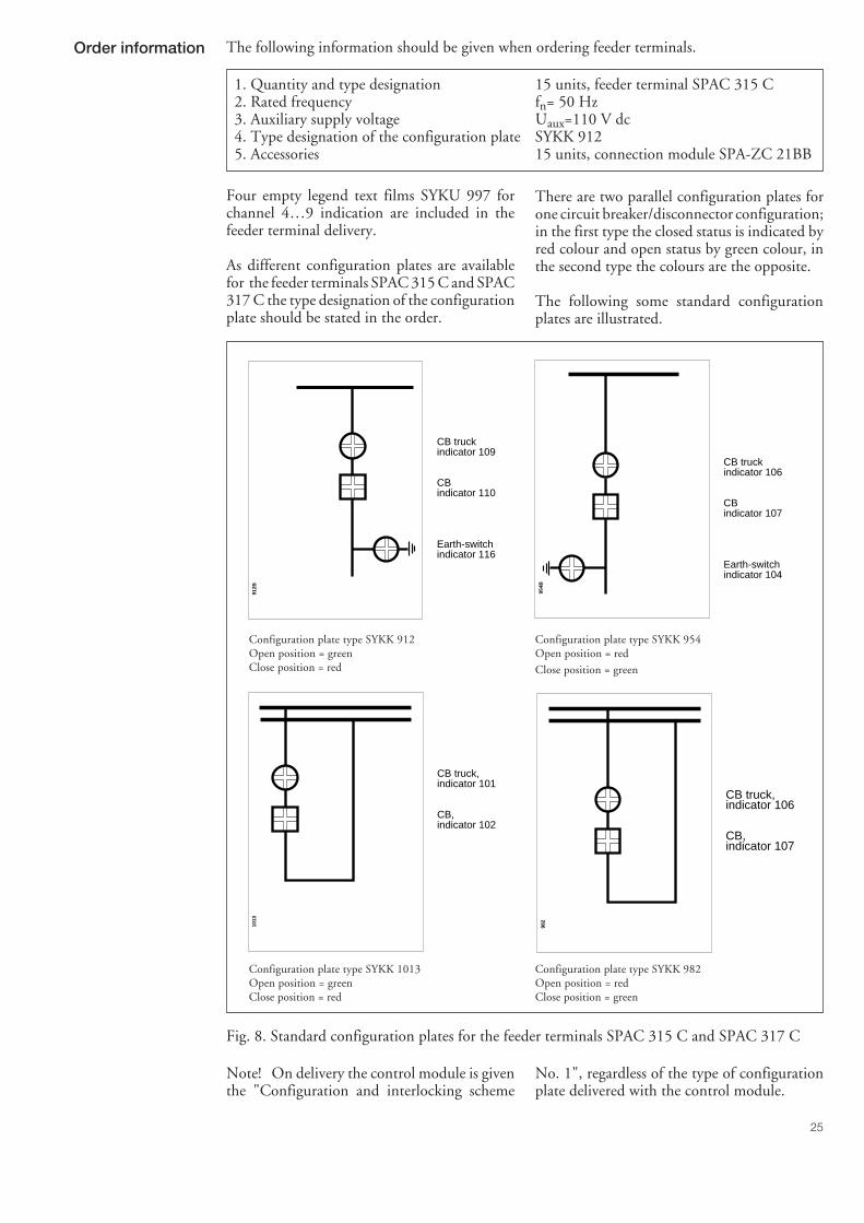
The following information should be given when ordering feeder terminals.
1. Quantity and type designation 15 units, feeder terminal SPAC 315 C2. Rated frequency fn= 50 Hz3. Auxiliary supply voltage Uaux=110 V dc4. Type designation of the configuration plate SYKK 9125. Accessories 15 units, connection module SPA-ZC 21BB
Four empty legend text films SYKU 997 forchannel 4…9 indication are included in thefeeder terminal delivery.
As different configuration plates are availablefor the feeder terminals SPAC 315 C and SPAC317 C the type designation of the configurationplate should be stated in the order.
912B
CB truckindicator 109
CBindicator 110
Earth-switchindicator 116
954B
CB truckindicator 106
CBindicator 107
Earth-switchindicator 104
There are two parallel configuration plates forone circuit breaker/disconnector configuration;in the first type the closed status is indicated byred colour and open status by green colour, inthe second type the colours are the opposite.
The following some standard configurationplates are illustrated.
Configuration plate type SYKK 912Open position = greenClose position = red
Configuration plate type SYKK 954Open position = red
Close position = green
1013
CB truck,indicator 101
CB,indicator 102
982
CB truck,indicator 106
CB,indicator 107
Configuration plate type SYKK 1013Open position = greenClose position = red
Configuration plate type SYKK 982Open position = redClose position = green
Fig. 8. Standard configuration plates for the feeder terminals SPAC 315 C and SPAC 317 C
Note! On delivery the control module is giventhe "Configuration and interlocking scheme
No. 1", regardless of the type of configurationplate delivered with the control module.
Order information

IRF2
5
RS 615 Ser.No. SPTO 1D6
O I
Uaux
30 ... 80 V _80 ... 265 V _
R
L
SG1
12
0 1
I
STEP
I
I
L1
L2
L3
[kA]
[kA]
[kA]
O
I
TEST
INTERLOCK
[MW]
[Mvar]
[GWh, MWh, kWh]
P
Q
E
RS 232
GAS PRESSURE
MOTOR VOLTAGE
fn = 50 60 Hz SPAC 3__ CnI = /0,2 1 A( )oInI = /1 5 A( )I
SPTO 1D6Control module
User´s manual and Technical description
2
1MRS 750118-MUM EN
Issued 95-08-31Modified 97-05-06Version CChecked TKApproved TK
Data subject to change without notice
SPTO 1D6Control module
Contents Description of functions ................................................................................................. 3Control functions ...................................................................................................... 3Measurement functions ............................................................................................. 3Supervision functions (modified 96-02) ..................................................................... 4Block schematic diagram ........................................................................................... 7
Front panel ..................................................................................................................... 8Object status indicators ............................................................................................. 8Indicators for input channels 4...9 ............................................................................. 9Operation indicators .................................................................................................. 9Local/Remote key switch ......................................................................................... 10Push-buttons for Select ∩ , Close I and Open O ..................................................... 10Switchgroup SG1 .................................................................................................... 10Display of measured values and serial data communicator parameters(modified 97-05) ...................................................................................................... 11Alarm indications of supervision functions .............................................................. 13RS 232 interface ...................................................................................................... 13
Setting .......................................................................................................................... 14Configuration .......................................................................................................... 14Interlocking ............................................................................................................. 17Conditional Direct Output Control ........................................................................ 20Input channels 4...13 ............................................................................................... 21Outputs ................................................................................................................... 22Scaling of measured values ....................................................................................... 23Energy measurement by integration ........................................................................ 24Event codes .............................................................................................................. 25Quick reference for setting ...................................................................................... 27Serial communication parameters (modified 96-02) ................................................ 28Default values of parameters .................................................................................... 34
Technical data ............................................................................................................... 35Appendix 1, Default configuration and interlocking 1 .................................................. 36Appendix 2, Default configuration and interlocking 2 .................................................. 37Appendix 3, Default configuration and interlocking 10................................................ 38
3
Description offunctions
Control functions
The control module type SPTO 1D6 is usedfor reading binary input signals and for localand remote status indication of the binary sig-nals. The control module also executes open andclose commands for controllable switching de-vices of the switchgear.
The input channels 1...3 are used for readingstatus information of the switching devices, i.e.circuit breakers and disconnectors here aftercalled objects. Each of these channels includestwo physical inputs, one for the "object open"and one for the "object closed" information. Thecontrol module indicates the status informationlocally on the front panel by means of LEDindicators and transfers the status informationto the substation level communication equip-ment using the SPA serial bus.
The control module reads the status informa-tion of max. 3 objects. The front panel of thecontrol module is provided with a LED matrixused for object status indication. The object sta-tus indication LEDs of the control module arefreely configurable by the user to match the com-binations of switching devices of the switchgearcubicles.
Input channels 4...13 consist of single binaryinput circuits. These channels are basically usedfor transferring binary signals, other than cir-cuit breaker and disconnector status informa-tion signals, over the SPA bus to the substationlevel system. The status of input channels 4...9
is indicated locally by LEDs on the front panelof the control module.
The control module is capable of providing openand close commands for one switching object.The commands may be given via the local push-buttons on the front panel, the SPA serial busor the input channels 4...13. The length of thepulse-shaped open or close signals can be deter-mined by the user.
An enable signal must be given by the inter-locking program before an open or close pulsecan be delivered. The enable signal is control-led by the status of input channels 1...3 and4...13 and the interlocking program written bythe user.
The signal outputs, signal 1...4, can be used forindicating the status of the input channels 4...13.The selected output is active as long as the in-put channel is in an active state.
The open, close or signal 1...4 outputs can becontrolled by the Direct Output Control pro-gram. This program resembles the interlockingprogram. The user can define under which cir-cumstances an output is to be activated. Thiscontrol of an output is determined by the sta-tus of input channels 1...3 and 4...13, the posi-tion of the local/remote key switch and the Di-rect Output Control program written by theuser.
Measurementfunctions
The control module SPTO 1D6 measures threephase currents and two mA signals. The mAinputs are used for measuring active and reac-tive power. External measuring transducers areneeded. The input channel 7 can be used as apulse counter for energy pulses. Energy can also
be calculated by integrating the measured powervalues over time.
The measured signal values can be scaled fordisplay locally and for remote transfer over theSPA bus as primary values.
4
Supervisionfunctions
The trip circuit supervision function and theenergizing current monitoring function can belocally disabled by turning switch switch SG1/2on the front panel in position 1. The locally
performed selection in the control module over-rides the selection made over the SPA bus, us-ing parameters S200 and S202.
Trip circuitsupervision(modified 96-02)
The trip circuit supervision unit in the controlmodule consists of three functional units; a con-stant current generator, a measuring and timedelay circuit and an output circuit for signal-ling. The input/output circuits are galvanicallyisolated from each other. The constant currentgenerator forces a 1.5 mA measuring current toflow through the circuit breaker trip circuit. Theconstant current generator is connected over theOPEN contact of the feeder terminal circuit.Under no-fault conditions the voltage over theOPEN contact or the constant current genera-tor must exceed 30 V dc, when the voltage dropcaused by the 1.5 mA measuring current in otherparts of the supervised circuit are observed.
Mathematically the operation condition can beexpressed as:
Uc - (Rh(ext.) + Rh(int.) + Rs) x Ic ≥ 30 V dc(Formula 1)
whereUc = operating voltage over the supervised
trip circuitIc = measuring current through the trip
circuit, approximately 1.5 mARh(ext.) = external shunt resistor valueRh(int.) = internal shunt resistor value, 1 kΩRs = trip coil resistance value
The resistor Rh(ext.) must be so calculated thatthe trip circuit supervision current through theresistor is low enough to leave the trip coil ofthe circuit breaker unaffected. On the otherhand the voltage drop over the resistor Rh(ext.)must not be too high to jeopardize the operat-ing condition presented in Formula 1 above.
The following values are recommended for re-sistor Rh(ext.) in figure 1:
Operating voltage Uc Shunt resistorRh(ext.)
48 V dc 1.2 kΩ, 5 W60 V dc 5.6 kΩ, 5 W
110 V dc 22 kΩ, 5 W220 V dc 33 kΩ, 5 W
5
Fig. 1. Operating principle of the supervision function of the trip circuit
The supervision of the trip circuit is based onthe constant current injection principle. If theresistance of the trip circuit, e.g. because of loosecontacts or oxidation, exceeds a certain limit orif the OPEN contact has welded, the voltageover the OPEN contact goes below 30 V dc andthe supervision function of the trip circuit isactivated. If the fault persists, a trip circuit su-pervision alarm signal in the form of a flashing"O.C.F." message (Open Circuit Fault) on thedisplay is obtained after the preset 3 s delay time.By default the alarm signal is connected to thealarm output contact SIGNAL 4. If this outputcontact is already used as an alarm output ofe.g. earth fault protection, by setting parameterS200= 2, the trip circuit supervision alarm canbe configured so that only display alarm andevent is generated.
The fault message can be locally acknowledgedby pressing the push-buttons STEP and SE-LECT ∩ simultaneously for about 1 s.
Note!Only the display indication needs acknowledg-ing, not the alarm signal output. The alarmoutput will reset automatically when the faultdisappears.
As a default and to avoid unnecessary alarms,the function of the trip circuit supervision isblocked when the trip signal TS2 initiated bythe protection module is activated, that is whenthe OPEN contact is closed. The trip circuitsupervision is also automatically disabled whenthe circuit breaker is withdrawn, i.e. when thefour-pole status of both CB and CB truck indi-cate "undefined" status (no voltage at binarystatus inputs). . The CB truck is defined by value"11" for object type on the configuration com-mand line. Further, in case of removed CB, theflashing position indicators of CB and CB truckshowing undefined status, can be set to beswitched off after 10 min timeout. This can bedone with parameter S7.
&
SG1/2=0
3s
O.C.F.
S200>0I
O
I>
+Uc
-Uc
66
97
96
65
Rh(ext)
Rh(int)
U>30V
SPAC 3__
S200=1
STEP+
OPEN
SIGNAL4
OPEN
6
Energizing currentinput circuitsupervision(modified 96-02)
The supervision function of the energizing cur-rent input circuit detects interruptions of theenergizing circuit. The supervision unit can begiven a two-phase or three-phase function withparameter S203. The supervision is based oncomparison between the measured phase cur-rents. If one or two phase currents exceed 12%of the rated value In, while in one or two phasesthe measured phase current is below 6% of therated current In, an alarm is given in the formof a flashing "C.I.F" message (Current InputFault) on the display after a set operate timedelay. By default the alarm signal is connectedto the alarm output contact SIGNAL 4. If thisoutput contact is already used as an alarm out-put of e.g. earth fault protection, by setting pa-rameter S202 = 2, the energizing current inputsupervision alarm can be configured so that onlydisplay alarm and event is generated.
The operate time delay can be set with param-eter S204 in the range of 3...60 s. The defaultvalue is 15 s. The monitoring function is disa-bled if all input currents are under 6% of In.The fault message can be locally acknowledgedby pressing the push-buttons STEP and SE-LECT ∩ simultaneously.
Note!Only the display indication needs acknowledg-ing, not the alarm signal output. The alarmoutput will reset automatically when the faultdisappears.
The phase current values can be called up onthe display by means of the STEP push-but-ton.
Fig. 2. Principle of the supervision function of the energizing current input circuit.
0.12xIn
0.12xIn
0.12xIn
>1
0.06xIn
0.06xIn
0.06xIn
IL1
IL2
IL3
&
SG1/2=0
3...60s
S204
C.I.F.STEP+SELECT
S202>0
S202=1
>1
SIGNAL4
7
Channels1…3
Channels4…13
t
Open /Close
Chann.4…9
Signal
output
control
Signal
1…3
Enable
SPA-bus
Readstatus
Open/closeoutputcontrol
Inter-locking
Readstatus
I O
SPA-bus
SPA-bus
Indication
Conditionaldirectoutputcontrol
Indication
1
1
Readstatus
Remote / Local-key switch
3I
SPTO 1D6
Indication
Q (mA2)
P (mA1)Measure-
ment
E ( )
SPA-bus
Channel 7
1
3I 3∆I/In
Readstatus
Trip
circuit
supervision
Signal 4R >
&
Block schematicdiagram
Fig. 3. Block schematic diagram of the control module SPTO 1D6.
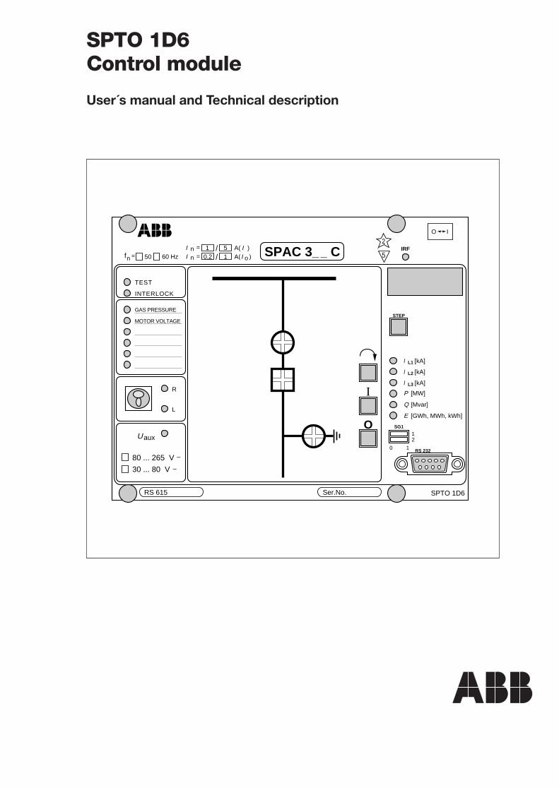
8
Front panel
Fig. 4. Front panel of the control module SPTO 1D6 without the configuration plate SYKK _ andthe channel legend text foil SYKU 997.
Object statusindicators
The front panel includes 16 indicator units witheach four rectangular LED indicators, two greenand two red. The indicator units are used forlocal status indication of the circuit breakers anddisconnectors of the switchgear cubicle. In thecontrol module SPTO 1D6 three of the 16 in-dicator units can be utilized at a time. The indi-cator units to be used are freely selectable bythe user, see chapter "Configuration".
A plastic configuration plate type SYKK_ witha printed mimic diagram is inserted into apocket in front of the object indicator units. Thebottom of the pocket is open. By selecting aproper configuration plate and by configuringa new combination of indicator units differentobject configurations of the switchgear cubiclecan be handled.
The configuration plate shows the combinationof circuit breakers and disconnectors of theswitchgear cubicle. The configuration plate fea-tures transparent windows for the status indi-cators that are in use. The status indicators notin use are hidden.
One indicator unit consists of four LEDs, twovertical and two horizontal. Two of the LEDsare red and two are green. The red LEDs arevertically and the green LEDs horizontally ar-ranged in columns 1 and 3, see Fig. 5. In col-umns 2 and 4 the green LEDs are vertically andthe red LEDs horizontally arranged. Due to this
system both colours can be used to indicate ei-ther the open or closed status of a switchingdevice.
Fig. 5. Example of a plastic configuration plateSYKK __. The actual size of the configurationplate is 72mm x 106.5 mm.
912B
5 IRF
O<->I
Serial No.
I
O
STEP
SG112
Uaux
80…265 V_30…80 V_
TEST
2
0 1
P [MW]
Q [MVar]
IL1 [kA]
IL2 [kA]
IL3 [kA]
E [GWh,MWh,kWh]
RS 615
R
L
fn= 50 60 HzIn = 1 / 5 A (I)In = 0.2 / 1 A (Io) SPAC 3_ _C
INTERLOCK
RS 232
SPTO 1D6
SelectClose andOpenpush-buttons
Operation indicators;output test and interlockedoperation
Indicators for inputchannels 4…9The pocket for channellegend text film SYKU 997
Remote/Local key switchIndicators for remote andlocal mode
Indicator for auxiliary power supplyVoltage range of powersupply and binary inputs
Type designation andrated values of the relaypackage
Simplified device symbol
Display for measured values
Self-supervisionalarm indicator
Display step push-button
Indicators for value currently on display
SelectorSwitchgroup SG1
RS 232 interface
Type designationof the module
Object status indication matrixThe pocket for configuration plate SYKK _
IO
9
CB CONDITION
GAS PRESSURE
MOTOR VOLTAGE
CB CONDITION
GAS PRESS.
MOTOR VOLT.
Drawn with1,8 mmlettering guide
Drawn with2,5 mmlettering guide
Indicators for inputchannels 4...9
The status of the input channels 4...9 is indi-cated locally by LEDs on the front panel. Chan-nel 4 is indicated by the topmost LED andchannel 9 by the bottom LED.
An input can be defined to be active when theinput signal is high (controlled by NO contact)or active when the input signal is low (control-led by NC contact). The LED is lit when theinput is active.
The indication of the active status of the inputchannels 4...9 can separately be programmed
to be memory controlled. If an input channelindicator is memory controlled the LED indi-cator remains lit until the channel is locally re-set by pressing the push-buttons STEP andSELECT simultaneously or by remote controlvia the serial interface using the parameter S5,which is given the value 0 or 1.
The front panel includes a pocket for the textlegend foil SYKU 997 on which the user canwrite the input channel texts. An clear text foilis delivered with the feeder terminal.
Fig. 6. Example of a text foil type SYKU 997. The foil is shown in its natural size, width 33.5 mmand height 34 mm.
Operation indicators The control module features two red operationindicators which show the status of the module
itself. These LEDs are normally dark. The indi-cators have the following functions:
Indicator Function
TEST The LED is lit when the switch SG1/1=1. In this position the interlockingfunctions are out of use.
INTERLOCK The LED is lit when a control command is given locally but the control ofthe object is prohibited by the interlocking program. The LED indicator canbe switched off by pushing the SELECT ∩ button but it is also automaticallyswitched off after about 30 s.
When the control module is in the programming mode and the interlockingsare in use the indicator lights and it is switched off when the operation modeis entered or when the interlockings are set out of use.
10
Local/Remotekey switch
The local I and O push-buttons, i.e. the OPENand CLOSE push-buttons, are made operativeby turning the key switch into the positionLOCAL, indicated by the yellow LED markedL. In this switch position all remote control sig-nals via the serial interface are inhibited.
Accordingly, to be able to control an object viathe serial communication, the key switch mustbe in the REMOTE position, indicated by theyellow LED marked R. When the key switch is
in the REMOTE position, local push-buttoncontrol is inhibited. Control signals via inputchannels 4...13 or the Direct Output Controlprogram are allowed both in the LOCAL andthe REMOTE position. The position informa-tion can also be included in the Direct OutputControl function.
The key of the key switch can be removed ineither position.
Push-buttons∩ , I and O
A local control sequence is started by pressingthe push-button SELECT ∩ . After that theLED indicator of the object which has beendefined controllable starts flashing.
If the object is closed the indicator for the closedposition starts flashing and if the object is openthe indicator for the open position starts flash-ing. The indicator remains flashing until a con-trol command is given or a timeout of 1 minutehas elapsed.
The close and open commands are given withthe I (CLOSE) or O (OPEN) push-buttons.Depending on the status of input channels 1...3and 4..13 and the interlocking function, thecontrol module either executes the selected com-mand or switches on the INTERLOCK-LEDto indicate that the operation is inhibited.
The lenght of the the control pulse can be set inthe range 0.1...100 s.
Switchgroup SG1Switch Function
SG1/1 Switch SG1/1 is used to inhibit interlockings during testin.
When SG1/1 = 0, the interlocking function is in use.When SG1/1 = 1, the interlocking function is out of use and the red TEST LED is lit.All control operations are allowed.
NOTE! Switch SG1/1 should be used only for test purposes.
SG1/2 Switch SG1/2 is used to inhibit trip circuit and energizing current supervision.
When SG1/2 = 0 the trip circuit and energizing current supervisions are alerted.When SG1/2 = 1 the trip circuit and energizing current supervisions are out of use.
11
Display of measuredvalues and serial datacommunicatorparameters
The displayed items can be stepped through bypressing the STEP push-button. The measuredvalues are presented by the three rightmost green
digits. A lit yellow LED indicator below theSTEP push-button shows which measured valueis indicated on the display.
Indicator Data to be displayed
IL1 [kA] Measured phase current IL1 in kiloamperes.The measuring range is 0.000...999 kA.
NOTE! 0.000 is indicated as .000
IL2 [kA] Measured phase current IL2 in kiloamperes.The measuring range is 0.000...999 kA.
IL3 [kA] Measured phase current IL3 in kiloamperes.The measuring range is 0.000...999 kA.
P [MW] Measured active power in megawatts. Both positive and negative val-ues are indicated. Positive values have no sign, negative values are in-dicated by a leftmost red minus sign on the display.
Q [MVar] Measured reactive power in megavars. Both positive and negative val-ues are indicated. Positive values have no sign, negative values are in-dicated by a leftmost red minus sign on the display.
E [GWh,MWh,kWh] Measured active energy. The measured value is displayed in three parts;in gigawatthours, in megawatthours and in kilowatthours.
The serial communication parameters, too, arepresented on the four-digit display. The address
of the data to be displayed is indicated by theleftmost red digit of the display.
Red digit Data to be displayed
A Serial communication address. May have a value within the range 0...254.The default value is 99.
B Serial communication baudrate. Selectable transmission rate 4.8 or 9.6 kBd.The default value is 9.6 kBd.
C Serial communication monitor. If the device is connected to a higher level datacommunication equipment and the communication system is operating, the moni-tor reading is 0, otherwise the numbers 0...255 are continuously scrolling on thedisplay.
The display can be selected to show a measuredvalue continuosly or to be switched off after a 5minutes timeout.
12
Display off
Current in phase L1 / kA
Current in phase L2 / kA
Current in phase L3 / kA
Current in phase L1 / A
Current in phase L2 / A
Current in phase L3 / A
1
1
3
2
3
2
1
Active power / MW
Reactive power / Mvar
Energy / GWh
Energy / MWh
3 Energy / kWh
Serial communication monitor
Data transfer rate / kBd
Serial communication addressA
b
C
2
Reverse step 0.5 s
Forward step 1 s
Fig. 7. Display menu of the control module SPTO 1D6.
(modified 97-05)
13
Alarm indicationsof supervisionfunctions
Energizing currentmonitoring
The energizing current monitoring alarm is lo-cally indicated with a flashing "C.I.F." (CurrentInput Fault) message on the display. The "C.I.F."message is acknowledged by pressing the STEPand SELECT ∩ push-buttons simultaneously.The measured phase current value can be called
up for display by means of the STEP push-but-ton, although the monitor is in the alarm state,but no other display menu items.
The energizing current monitoring function canbe disabled with switch SG1/2.
Trip circuitsupervision
The trip circuit supervision alarm is locally in-dicated with a flashing "O.C.F." (Open CircuitFault) message on the display. The "O.C.F."message is acknowledged by pressing the STEPand SELECT ∩ push-buttons simultaneously.
After acknowledge the display will reset, if the
fault has disappeared. If the fault still exists, thesteady "O.C.F." message remains on until thefault is cleared. The alarm contact output is au-tomatically reset when the fault disappears.
The trip circuit supervision function can be disa-bled with switch SG1/2.
RS 232 interface The 9-pole RS 232 interface on the front panelis used for setting the control module via a PC.The entire serial communication of the feederterminal goes over the control module SPTO1D6. This enables protection modules of thesame feeder terminal to be set via the RS 232interface of the control module.
If a PC is connected to the RS 232 interface theRS 485 interface on the rear panel of the feederterminal is disconnected. The use of the RS 232interface requires a SPA bus protocol.
The following serial communication parametersshould be used:
- Number of data bits, 7- Number of stop bits, 1- Parity, even- Baudrate, 9.6 kilobauds as a default
The table below shows the signal names and pinnumbers of the cable to be used between theRS 232 interface and the devise used for set-ting.
RS 232 interface of SPTO 1D6 Setting device
Signal name Pin number Pin number Pin number Signal name9-pin male conn. 9-pin female conn. 25-pin male conn.
Data receive, Rx 2 3 2 Datatransmit, Tx
Data transmit, Tx 3 2 3 Datareceive, Rx
Earth 5 5 7 EarthDSR 6 4 20 DTRDTR, +12V 4 - - -
Pin 4 of the RS 232 interface of the controlmodule SPTO 1D6 can be used for feeding sup-ply voltage to an optic modem. An optic mo-
dem may be necessary between the controlmodule and the programming device if the pos-sible potential difference cannot be eliminated.
14
Setting
Configuration
The control module SPTO 1D6 is capable ofindicating status of 3 objects, i.e. circuit breaker,CB truck or disconnectors and controlling(opening or closing) one object.
The control module suits different circuitbreaker/disconnector/earthing switch configu-rations within the above mentioned limits. Theconfiguration can be freely selected by using theconfiguration commands explained below or bychoosing a suitable default configuration. Eachdefault configuration uses a fixed interlockingscheme.
The default configurations and correspondinginterlocking programs are explained in the ap-pendices 1...3. If the configuration or the in-terlocking program is not suitable for a certainapplication, then both must be selected by theuser.
After factory testing the default configurationand interlocking 1 has been selected for the con-trol module. Another default configuration ischosen by writing the configuration number forthe setting parameter S100 via the SPA bus.
Normally the control module is in the opera-tion mode which means that the interlockingprogram is executed. When setting a configura-tion or selecting a new default configuration thecontrol module must be in the program mode,i.e. the setting parameter S198=0.
Example 1Selection of the default configuration and in-terlocking 10 instead of default 1.
>99WS198:0:XX; Enter into setting mode
>99WS100:10:XX; Select the default 10
>99WS198:1:XX; Change into run mode
>99WV151:1:XX; Store the set parameters
If the setting parameter S100 is 0, the configu-ration is freely programmable. In this case allindicators are initially set out of use. In a freelyprogrammable configuration, only the objectsto be used must be programmed.
The three input channels 1...3 are used to readstatus data of circuit breaker and disconnectors.The input channel numbers are used when thecircuit breaker/disconnector configuration is set.
The code numbers of the indicator units on thefront panel range from 101...116 and they areused when the feeder terminal is configured. Thelocation and the code numbers of the indicatorunits in the matrix are shown in Fig. 8.
Fig. 8. Position, code number and colour of theindicator units on the front panel of the con-trol module SPTO 1D6.
The control module has two outputs, OPENand CLOSE, for the control of one object. Thecontrol outputs have their own code numbers,20 and 21, which have to be used when the con-trol module is configured. The output codenumbers correspond to the following functions:
Output code number Function
20 OPEN21 CLOSE
For the correspondence between the input andoutput codes and the terminal numbers on therear panel of the feeder terminal, see chapter"Connection diagram" in the User´s manual forthe feeder terminal.
A configuration is set by linking the indicatornumber, the four-pole input number and theoutput code number by using a SPA protocolcommand.
The setting parameters S101...S116 which cor-respond to the indicator code numbers 101...116 are reserved for the configuration com-mands. Either the OPEN code (e.g.20) or theCLOSE code (e.g.21) can be used as an outputcode number. Also some other parameters, suchas object type and the location of open andclosed status indicators, are specified in the SPAinstruction.
116
109
110
115
114
113105
106
107
111
112
101
102
103
104
108
Green
Red
Column 1 2 3 4
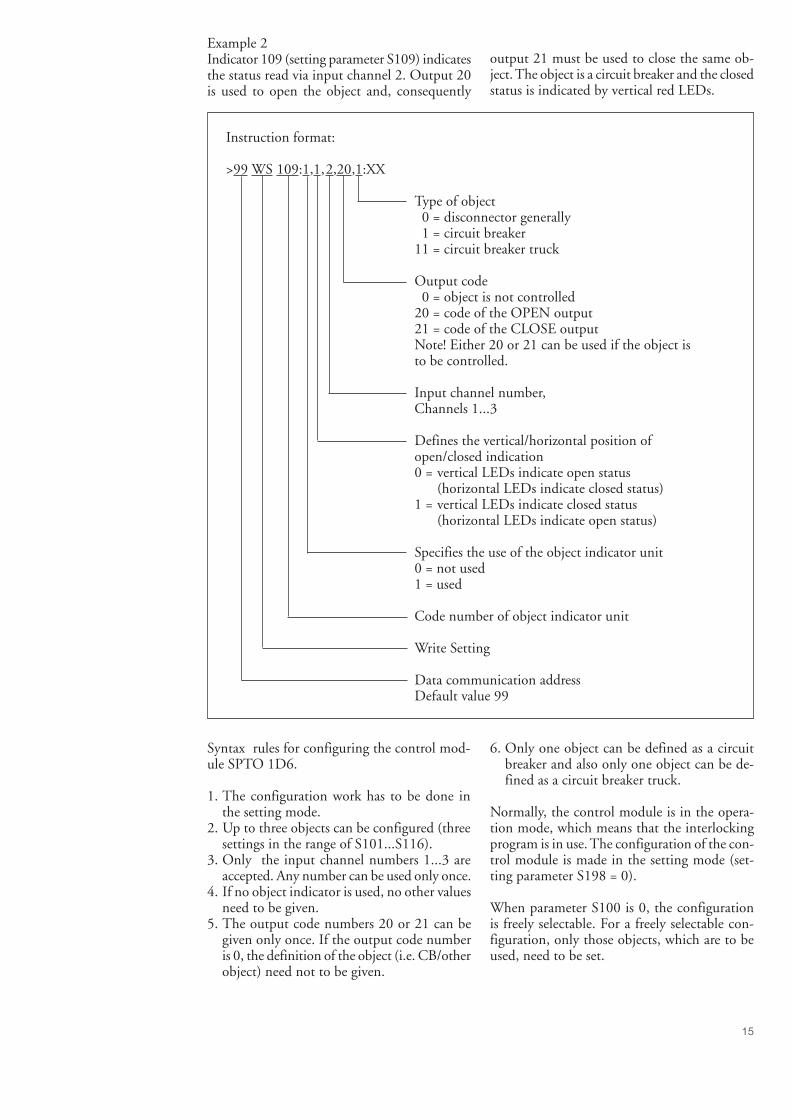
15
Example 2Indicator 109 (setting parameter S109) indicatesthe status read via input channel 2. Output 20is used to open the object and, consequently
output 21 must be used to close the same ob-ject. The object is a circuit breaker and the closedstatus is indicated by vertical red LEDs.
Instruction format:
>99 WS 109:1,1,2,20,1:XX
Type of object 0 = disconnector generally 1 = circuit breaker11 = circuit breaker truck
Output code 0 = object is not controlled20 = code of the OPEN output21 = code of the CLOSE outputNote! Either 20 or 21 can be used if the object isto be controlled.
Input channel number,Channels 1...3
Defines the vertical/horizontal position ofopen/closed indication0 = vertical LEDs indicate open status
(horizontal LEDs indicate closed status)1 = vertical LEDs indicate closed status
(horizontal LEDs indicate open status)
Specifies the use of the object indicator unit0 = not used1 = used
Code number of object indicator unit
Write Setting
Data communication addressDefault value 99
Syntax rules for configuring the control mod-ule SPTO 1D6.
1. The configuration work has to be done inthe setting mode.
2. Up to three objects can be configured (threesettings in the range of S101...S116).
3. Only the input channel numbers 1...3 areaccepted. Any number can be used only once.
4. If no object indicator is used, no other valuesneed to be given.
5. The output code numbers 20 or 21 can begiven only once. If the output code numberis 0, the definition of the object (i.e. CB/otherobject) need not to be given.
6. Only one object can be defined as a circuitbreaker and also only one object can be de-fined as a circuit breaker truck.
Normally, the control module is in the opera-tion mode, which means that the interlockingprogram is in use. The configuration of the con-trol module is made in the setting mode (set-ting parameter S198 = 0).
When parameter S100 is 0, the configurationis freely selectable. For a freely selectable con-figuration, only those objects, which are to beused, need to be set.
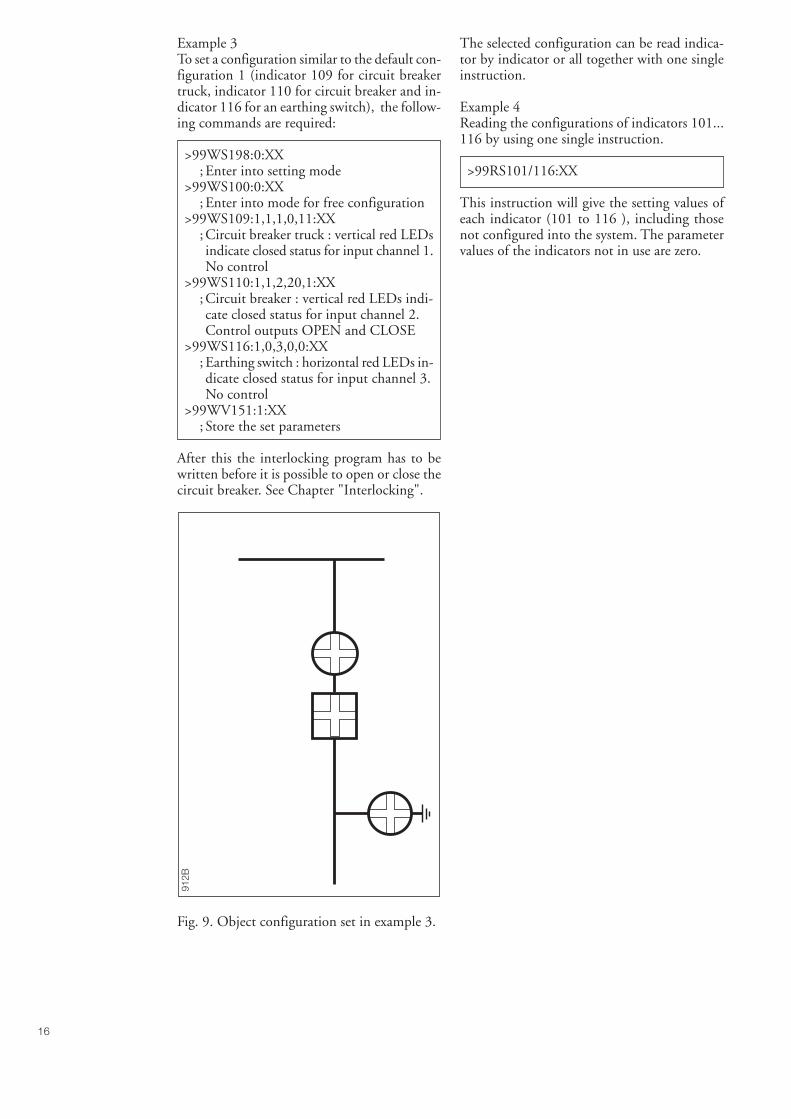
16
Example 3To set a configuration similar to the default con-figuration 1 (indicator 109 for circuit breakertruck, indicator 110 for circuit breaker and in-dicator 116 for an earthing switch), the follow-ing commands are required:
>99WS198:0:XX; Enter into setting mode
>99WS100:0:XX; Enter into mode for free configuration
>99WS109:1,1,1,0,11:XX; Circuit breaker truck : vertical red LEDsindicate closed status for input channel 1.No control
>99WS110:1,1,2,20,1:XX; Circuit breaker : vertical red LEDs indi-cate closed status for input channel 2.Control outputs OPEN and CLOSE
>99WS116:1,0,3,0,0:XX; Earthing switch : horizontal red LEDs in-dicate closed status for input channel 3.No control
>99WV151:1:XX; Store the set parameters
After this the interlocking program has to bewritten before it is possible to open or close thecircuit breaker. See Chapter "Interlocking".
The selected configuration can be read indica-tor by indicator or all together with one singleinstruction.
Example 4Reading the configurations of indicators 101...116 by using one single instruction.
>99RS101/116:XX
This instruction will give the setting values ofeach indicator (101 to 116 ), including thosenot configured into the system. The parametervalues of the indicators not in use are zero.
912B
Fig. 9. Object configuration set in example 3.
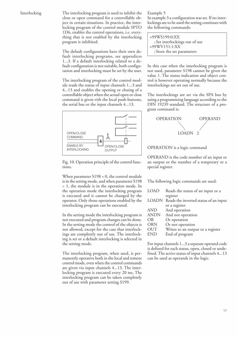
17
Interlocking The interlocking program is used to inhibit theclose or open command for a controllable ob-ject in certain situations. In practice, the inter-locking program of the control module SPTO1D6, enables the control operations, i.e. every-thing that is not enabled by the interlockingprogram is inhibited.
The default configurations have their own de-fault interlocking programs, see appendices1...3. If a default interlocking related to a de-fault configuration is not suitable, both configu-ration and interlocking must be set by the user.
The interlocking program of the control mod-ule reads the status of input channels 1...3 and4...13 and enables the opening or closing of acontrollable object when the actual open or closecommand is given vith the local push-buttons,the serial bus or the input channels 4...13.
Fig. 10. Operation principle of the control func-tions.
When parameter S198 = 0, the control moduleis in the setting mode, and when parameter S198= 1, the module is in the operation mode. Inthe operation mode the interlocking programis executed and it cannot be changed by theoperator. Only those operations enabled by theinterlocking program can be executed.
In the setting mode the interlocking program isnot executed and program changes can be done.In the setting mode the control of the objects isnot allowed, except for the case that interlock-ings are completely out of use. The interlock-ing is set or a default interlocking is selected inthe setting mode.
The interlocking program, when used, is per-manently operative both in the local and remotecontrol mode, even when the control commandsare given via input channels 4...13. The inter-locking program is executed every 20 ms. Theinterlocking program can be taken completelyout of use with parameter setting S199.
OPEN/CLOSE COMMAND
ENABLE BYINTERLOCKING
& OPEN/CLOSE OUTPUT
t
Example 5In example 3 a configuration was set. If no inter-lockings are to be used the setting continues withthe following commands:
>99WS199:0:XX; Set interlockings out of use
>99WV151:1:XX; Store the set parameters
In this case when the interlocking program isnot used, parameter S198 cannot be given thevalue 1. The status indication and object con-trol is however operating normally because theinterlockings are set out of use.
The interlockings are set via the SPA bus byusing a programming language according to theDIN 19239 standard. The structure of a pro-gram command is:
OPERATION OPERAND
LOADN 2
OPERATION is a logic command
OPERAND is the code number of an input oran output or the number of a temporary or aspecial register.
The following logic commands are used:
LOAD Reads the status of an input or aregister
LOADN Reads the inverted status of an inputor a register
AND And operationANDN And not operationOR Or operationORN Or not operationOUT Writes to an output or a registerEND End of program
For input channels 1...3 a separate operand codeis defined for each status, open, closed or unde-fined. The active status of input channels 4...13can be used as operands in the logic.
18
In SPTO 1D6 the following operand values canbe used with the operations LOAD, LOADN,AND, ANDN, OR, ORN:
1...3 = input channel number; input code, if the status "closed"is used in the logic
101...103 = input channel number + 100; input code , if the status "unde-fined" is used in the logic
201...203 = input channel number + 200; input code, if the status "open" isused in the logic
4...13 = input channel number; input code, if the status "active"is used in the logic
70...89 ; Number of a temporary register60 and 61 ; Number of a special register62 ; Position information of the L/R
key switch
In control module SPTO 1D6 the followingoperand values can be used with operationOUT:
20 or 21 ; Output code number70...89 ; Number of a temporary register
The input channel numbers and the outputcodes are the same as those defined when theconfiguration was set.
The two special registers, 60 and 61, have con-stant values; register 60 is always zero (0) andregister 61 is one (1). Register 62 is used forposition information of the L/R key switch; reg-ister 62 is one (1) when the L/R key switch is inREMOTE position and zero (0) when the keyswitch is in LOCAL position. The registers70...89 are used as temporary data storages dur-ing the interlocking program execution.
Example 6How to store the result of a logic operation intoa temporary register.
>99WM200:LOAD 201:XX; Read the open status of an object wiredto input 1
>99WM201:AND 202:XX; Read the open status of an object wiredto input 2
>99WM202:OUT 70:XX; Write the result of the logic operationinto register 70
After these commands the value of register 70is 1, if both objects are open.
Example 7How to use input channels 4...13 in the logic.
>99WM200:LOAD 1:XX; Read the closed status of an object wiredto input 1
>99WM201:AND 4:XX; Read the active status of input channel 4
>99WM202:OUT 20:XX; Enable output 20
After these commands the output OPEN (code20) is enabled if object 1 is closed and inputchannel 4 is active.
Syntax rules for setting the interlocking logicfor the control module SPTO 1D6:
1. The setting has to be done in the settingmode.
2. With the interlocking program the operatordefines when the opening and closing of anobject is allowed.
3. The setting parameters M200...M300 areused. A setting parameter is equal to the linenumber of the interlocking program.
4. The interlocking program always begins withM200. No empty lines are permitted.
5. The interlocking program always starts witha LOAD or LOADN command.
6. The last command of the program must beEND.
7. One operand can be used only once with theOUT command.
8. Before the LOAD and LOADN commands,except for the first one, the OUT commandshould be used.
9. Before the END command the commandOUT should be used.
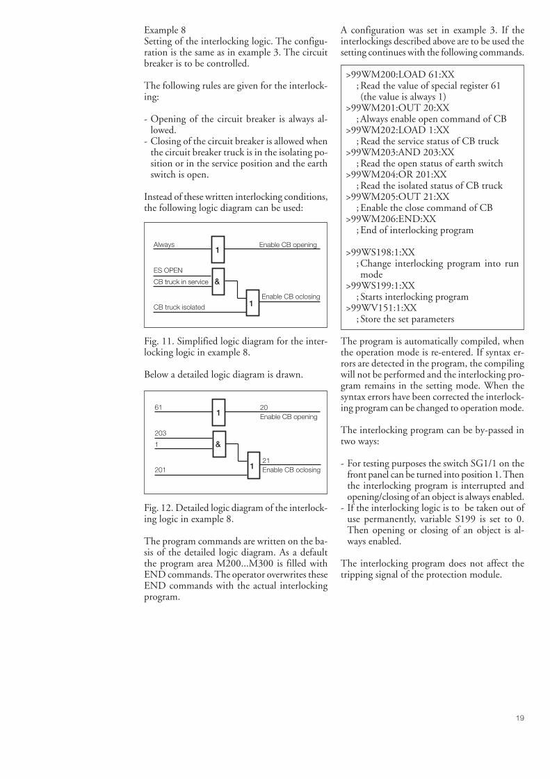
19
Example 8Setting of the interlocking logic. The configu-ration is the same as in example 3. The circuitbreaker is to be controlled.
The following rules are given for the interlock-ing:
- Opening of the circuit breaker is always al-lowed.
- Closing of the circuit breaker is allowed whenthe circuit breaker truck is in the isolating po-sition or in the service position and the earthswitch is open.
Instead of these written interlocking conditions,the following logic diagram can be used:
Fig. 11. Simplified logic diagram for the inter-locking logic in example 8.
Below a detailed logic diagram is drawn.
Fig. 12. Detailed logic diagram of the interlock-ing logic in example 8.
The program commands are written on the ba-sis of the detailed logic diagram. As a defaultthe program area M200...M300 is filled withEND commands. The operator overwrites theseEND commands with the actual interlockingprogram.
A configuration was set in example 3. If theinterlockings described above are to be used thesetting continues with the following commands.
>99WM200:LOAD 61:XX; Read the value of special register 61(the value is always 1)
>99WM201:OUT 20:XX; Always enable open command of CB
>99WM202:LOAD 1:XX; Read the service status of CB truck
>99WM203:AND 203:XX; Read the open status of earth switch
>99WM204:OR 201:XX; Read the isolated status of CB truck
>99WM205:OUT 21:XX; Enable the close command of CB
>99WM206:END:XX; End of interlocking program
>99WS198:1:XX; Change interlocking program into runmode
>99WS199:1:XX; Starts interlocking program
>99WV151:1:XX; Store the set parameters
The program is automatically compiled, whenthe operation mode is re-entered. If syntax er-rors are detected in the program, the compilingwill not be performed and the interlocking pro-gram remains in the setting mode. When thesyntax errors have been corrected the interlock-ing program can be changed to operation mode.
The interlocking program can be by-passed intwo ways:
- For testing purposes the switch SG1/1 on thefront panel can be turned into position 1. Thenthe interlocking program is interrupted andopening/closing of an object is always enabled.
- If the interlocking logic is to be taken out ofuse permanently, variable S199 is set to 0.Then opening or closing of an object is al-ways enabled.
The interlocking program does not affect thetripping signal of the protection module.
1
&
1
Always Enable CB opening
ES OPEN
CB truck in service
CB truck isolated
Enable CB oclosing
1
&
1
61 20Enable CB opening
203
1
20121Enable CB oclosing
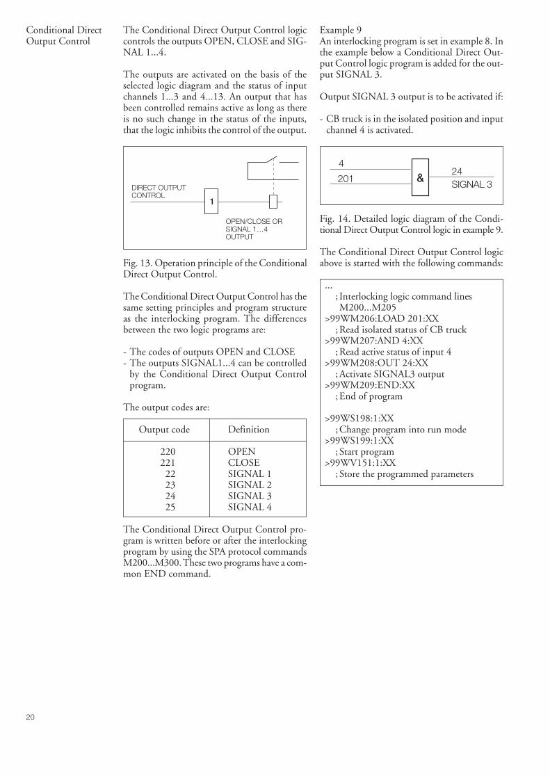
20
Conditional DirectOutput Control
The Conditional Direct Output Control logiccontrols the outputs OPEN, CLOSE and SIG-NAL 1...4.
The outputs are activated on the basis of theselected logic diagram and the status of inputchannels 1...3 and 4...13. An output that hasbeen controlled remains active as long as thereis no such change in the status of the inputs,that the logic inhibits the control of the output.
Fig. 13. Operation principle of the ConditionalDirect Output Control.
The Conditional Direct Output Control has thesame setting principles and program structureas the interlocking program. The differencesbetween the two logic programs are:
- The codes of outputs OPEN and CLOSE- The outputs SIGNAL1...4 can be controlled
by the Conditional Direct Output Controlprogram.
The output codes are:
Output code Definition
220 OPEN221 CLOSE
22 SIGNAL 123 SIGNAL 224 SIGNAL 325 SIGNAL 4
The Conditional Direct Output Control pro-gram is written before or after the interlockingprogram by using the SPA protocol commandsM200...M300. These two programs have a com-mon END command.
Example 9An interlocking program is set in example 8. Inthe example below a Conditional Direct Out-put Control logic program is added for the out-put SIGNAL 3.
Output SIGNAL 3 output is to be activated if:
- CB truck is in the isolated position and inputchannel 4 is activated.
Fig. 14. Detailed logic diagram of the Condi-tional Direct Output Control logic in example 9.
The Conditional Direct Output Control logicabove is started with the following commands:
...; Interlocking logic command linesM200...M205
>99WM206:LOAD 201:XX; Read isolated status of CB truck
>99WM207:AND 4:XX; Read active status of input 4
>99WM208:OUT 24:XX; Activate SIGNAL3 output
>99WM209:END:XX; End of program
>99WS198:1:XX; Change program into run mode
>99WS199:1:XX; Start program
>99WV151:1:XX; Store the programmed parameters
DIRECT OUTPUTCONTROL
1
OPEN/CLOSE OR SIGNAL 1…4OUTPUT
&201
424SIGNAL 3
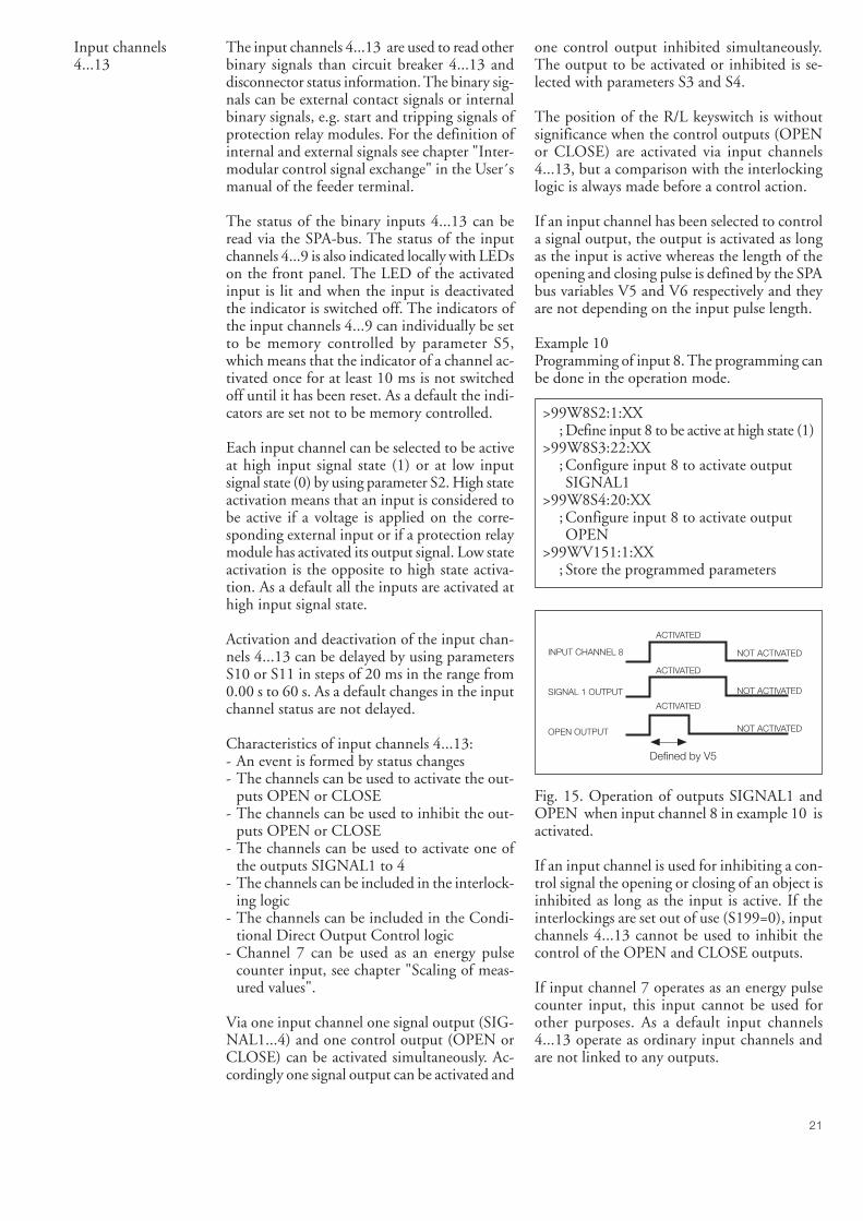
21
Input channels4...13
The input channels 4...13 are used to read otherbinary signals than circuit breaker 4...13 anddisconnector status information. The binary sig-nals can be external contact signals or internalbinary signals, e.g. start and tripping signals ofprotection relay modules. For the definition ofinternal and external signals see chapter "Inter-modular control signal exchange" in the User´smanual of the feeder terminal.
The status of the binary inputs 4...13 can beread via the SPA-bus. The status of the inputchannels 4...9 is also indicated locally with LEDson the front panel. The LED of the activatedinput is lit and when the input is deactivatedthe indicator is switched off. The indicators ofthe input channels 4...9 can individually be setto be memory controlled by parameter S5,which means that the indicator of a channel ac-tivated once for at least 10 ms is not switchedoff until it has been reset. As a default the indi-cators are set not to be memory controlled.
Each input channel can be selected to be activeat high input signal state (1) or at low inputsignal state (0) by using parameter S2. High stateactivation means that an input is considered tobe active if a voltage is applied on the corre-sponding external input or if a protection relaymodule has activated its output signal. Low stateactivation is the opposite to high state activa-tion. As a default all the inputs are activated athigh input signal state.
Activation and deactivation of the input chan-nels 4...13 can be delayed by using parametersS10 or S11 in steps of 20 ms in the range from0.00 s to 60 s. As a default changes in the inputchannel status are not delayed.
Characteristics of input channels 4...13:- An event is formed by status changes- The channels can be used to activate the out-
puts OPEN or CLOSE- The channels can be used to inhibit the out-
puts OPEN or CLOSE- The channels can be used to activate one of
the outputs SIGNAL1 to 4- The channels can be included in the interlock-
ing logic- The channels can be included in the Condi-
tional Direct Output Control logic- Channel 7 can be used as an energy pulse
counter input, see chapter "Scaling of meas-ured values".
Via one input channel one signal output (SIG-NAL1...4) and one control output (OPEN orCLOSE) can be activated simultaneously. Ac-cordingly one signal output can be activated and
one control output inhibited simultaneously.The output to be activated or inhibited is se-lected with parameters S3 and S4.
The position of the R/L keyswitch is withoutsignificance when the control outputs (OPENor CLOSE) are activated via input channels4...13, but a comparison with the interlockinglogic is always made before a control action.
If an input channel has been selected to controla signal output, the output is activated as longas the input is active whereas the length of theopening and closing pulse is defined by the SPAbus variables V5 and V6 respectively and theyare not depending on the input pulse length.
Example 10Programming of input 8. The programming canbe done in the operation mode.
>99W8S2:1:XX; Define input 8 to be active at high state (1)
>99W8S3:22:XX; Configure input 8 to activate outputSIGNAL1
>99W8S4:20:XX; Configure input 8 to activate outputOPEN
>99WV151:1:XX; Store the programmed parameters
Fig. 15. Operation of outputs SIGNAL1 andOPEN when input channel 8 in example 10 isactivated.
If an input channel is used for inhibiting a con-trol signal the opening or closing of an object isinhibited as long as the input is active. If theinterlockings are set out of use (S199=0), inputchannels 4...13 cannot be used to inhibit thecontrol of the OPEN and CLOSE outputs.
If input channel 7 operates as an energy pulsecounter input, this input cannot be used forother purposes. As a default input channels4...13 operate as ordinary input channels andare not linked to any outputs.
INPUT CHANNEL 8
SIGNAL 1 OUTPUT
OPEN OUTPUT
NOT ACTIVATED
NOT ACTIVATED
NOT ACTIVATED
ACTIVATED
ACTIVATED
ACTIVATED
Defined by V5
22
Outputs The control module SPTO 1D6 has six (6) out-puts: four signal outputs (SIGNAL1...4) andtwo control outputs (OPEN and CLOSE). Forthe purpose of setting the outputs are coded inthe following way:
Output Output Remarkscode
OPEN 20 For configuration andinterlocking
OPEN 220 For Conditional DirectOutput Control
CLOSE 21 For configuration andinterlocking
CLOSE 221 For Conditional DirectOutput Control
SIGNAL1 22SIGNAL2 23SIGNAL3 24SIGNAL4 25
The outputs OPEN and CLOSE can be con-trolled in four ways:
- Locally by means of the OPEN and CLOSEpush-buttons on the front panel of the con-trol module
- Remotely by commands over the SPA bus- Remotely via the binary input channels 4...13,
see chapter "Input channels 4...13"- By the Conditional Direct Output Control
logic, see chapter "Conditional Direct Out-put Control"
For the selection of the objects to be controlledvia the OPEN and CLOSE outputs, see chap-ter "Configuration".
When the first three ways of operation are usedthe OPEN and CLOSE outputs deliver pulses.Before an output can be activated the opera-tion must be enabled by the interlocking logic.
The open and close pulse lengths of the out-puts are determined by SPA bus variables V5and V6. The pulse length has to be determinedonly for the input channel to which the objectto be controlled is connected. As a default theobject to be controlled is connected to inputchannel 2.
The pulse length can be set within the range0.1...100 s with a time resolution of 0.1 s. As adefault the value for SPA bus variables V5 andV6 in input channel 2 is 0.1 s.
Example 11The pulse lengths can be set in the operationmode. In default configuration 3 the object tobe controlled is configured to input channel 2and defined to be a CB. The following SPA buscommands are used to set the open and closepulse lengths.
>99W2V5:0.5:XX; Set the open pulse length at 0.5 seconds
>99W2V6:0.2:XX; Set the close pulse length at 0.2 seconds
>99WV151:1:XX; Store the programmed parameters
The open and close commands are given viaserial communication to the input channel onwhich the object to be controlled is located. Theoutputs OPEN and CLOSE can be controlledvia serial communication according to two prin-ciples:- Direct control: An output command is given
by using parameter O1. When this parameterhas been given the value 0 (open) or 1 (close)the corresponding output pulse is given pro-vided the operation is enabled by the inter-locking program.
- Secured control: Initially the output is set intoa state of alert by means of parameter V1 foropening and parameter V2 for closing. Afterthat the corresponding output command is ex-ecuted by means of parameter V3, if enabledby the interlocking program. The state of alertis automatically cancelled when the executecommand has been given. The state of alertcan also be cancelled by parameter V4.
When the Conditional Direct Output Controllogic is used to control the outputs OPEN andCLOSE, the output is activated as long as thestatus of the input control signal remains un-changed.
The operation of the outputs OPEN andCLOSE can be inhibited in two ways:- By the interlocking program, see chapter "In-
terlocking"- By input channels 4...13, see chapter "Input
channels 4...13"
The outputs SIGNAL1...4 can be controlled intwo ways:- By input channels 4...13, see chapter "Input
channels 4...13"- By the Conditional Direct Output Control
logic program, see chapter "Conditional Di-rect Output Control"
Note!Output SIGNAL4 is also controlled by the su-pervision functions if in use.
23
The control module SPTO 1D6 includes a self-supervision system which controls a signal out-put, IRF. The output is activated when the aux-iliary power is connected and no fault has beendetected by the self-supervision system.
The output signal is deactivated if the auxiliarypower supply of the equipment is switched offor a permanent internal fault has been detected.The self-supervision output is connected to thecommon IRF output of the feeder terminal.
Scaling ofmeasured values
The control module measures three phase cur-rents, active and reactive power and energy. Thephase currents are measured via the 1 A or 5 Acurrent inputs of the feeder terminal. The mod-ule includes two mA-inputs for measuring ac-tive and reactive power via external measuringtransducers. Energy can be measured in twoways, either by using input 7 as a pulse counteror by integrating the measured power. If thepulse counter input is used an external energymeter with a pulse output is needed.
Phase currents
The three phase currents are displayed locallyas kA values and transferred via the SPA bus askiloampere values. However, to be able to dothis the measured values must be scaled, usingthe information about the rated current of theprimary side of the current transformers.
Example 12Scaling of a measured phase current value.
The rated current of the primary side of thecurrent transformers is 400 A. For scaling thecurrent must be given in amperes. The scalingfactor is 400.00.
>99WS9:400.00:XX; Set scaling factor S9 at 400.00
>99WV151:1:XX; Store the set parameters
The scaling factor can be set within the range0.00...10000.00. The default value of variableS9 after factory testing is 200.00.
Active and reactive power
Active power is displayed locally and transferredvia the SPA bus as megawatt (MW) values.Correspondingly the value of reactive power isdisplayed locally and transferred via the serialbus as megavar (Mvar) values. The power ismeasured in both directions. Positive values haveno sign and negative values are indicated by thered minus sign.
Power measurement can be enabled or disabledwith parameter S91. As a default power meas-urement is disabled (S91=0).
The input signal range of the mA-inputs is-20...0...+20 mA. The following setting param-eters are used for scaling the inputs:
S12 = Low limit of mA signal related to activepower
S13 = High limit of mA signal related to activepower
S14 = Low limit of mA signal related to reac-tive power
S15 = High limit of mA signal related to reac-tive power
S16 = Value of active power corresponding tomA signal at low limit
S17 = Value of active power corresponding tomA signal at high limit
S18 = Value of reactive power corresponding tomA signal at low limit
S19 = Value of reactive power corresponding tomA signal at high limit
When power measurement has been enabled thelow and high limits of the mA signals are firstgiven and then the corresponding values of ac-tive and reactive power.
Example 13Active power is to be measured in the range-50 MW...+135 MW and the corresponding mArange is -20 mA...20 mA.
>99WS91:1:XX; Enable power measurement
>99WS12:-20:XX; Set low limit of mA signal
>99WS13:+20:XX; Set high limit of mA signal
>99WS16:-50.00:XX; Set value of power corresponding to setlow mA signal limit
99WS17:+135.00:XX; Set value of power corresponding to sethigh mA signal limit
>WV151:1:XX; Store set parameters
24
Example 14Reactive power is to be measured in the range0...2.2 Mvar and the corresponding mA signalrange is 4...20 mA.
>99WS91:1:XX; Enable power measurement
>99WS14:+4:XX; Set low limit of mA signal
>99WS15:+20:XX; Set high limit of mA signal
>99WS18:+0.00:XX; Set value of power corresponding to lowmA signal limit
>99WS19:+2.20:XX; Set value of power corresponding to highmA signal limit
>99WV151:1:XX; Store set parameters
The scaled active and reactive power values canbe transmitted to remote control systems overthe SPA bus by using variable V3 for activepower and variable V4 for reactive power.
Energy
Input channel 7 can be used as an energy pulsecounter. The measured energy is displayed lo-cally by three digits in three parts; in kilowatt-hours, in megawatthours and in gigawatthours.Correspondingly, the energy value can be readvia the serial bus in three parts with maximumthree digits (parameters V8...V10) but also asone part in kilowatthours with maximum ninedigits (parameter V5). Before the energy pulsecounter can be used the energy measurementmust be enabled by variable S92. The defaultsetting of variable S92 is 0, which means thatenergy measurement is disabled.
The following parameters must be defined forinput channel 7:
S1 = definition of input channel 70 = general binary input (default)1 = pulse counter input without local
LED indication on front panel2 = pulse counter input with local LED
indication on front panelS2 = pulse direction
0 = negative pulse1 = positive pulse (default)
The following parameters must be defined forchannel 0:
S3 = definition of kWh value per pulse, settingrange 0.00...1000 kWh per pulse. Defaultsetting is 1.
Example 15Energy measurement via input channel 7 de-fined as pulse counter input.
>99WS92:1:XX; Enable energy measurement
>99WS3:5:XX; Set energy value 5 kWh per pulse
>99W7S1:1:XX; Set input 7 as a pulse counter withoutlocal indication
>99W7S2:1:XX; Set a positive polarity of pulses
>99WV151:1:XX; Store the programmed parameters
Energy measurementby integration
Energy can also be measured by integrating themeasured active and reactive power over time.In this case the measured active energy in onedirection is displayed locally, whereas both posi-tive and negative active and reactive energy val-ues can be read over the SPA bus.
The integration is used automatically if energymeasurement is enabled by parameter S92 andinput channel 7 has not been defined as a pulsecounter input.
Example 16Energy measurement by integrating the meas-ured power value over time. Initially the powermeasurement must be enabled and the powervalues scaled, see examples 13 and 14.
>99WS92:1:XX; Enable energy measurement
>99WV151:1:XX; Store the set parameters
25
Event codes Over the SPA bus a substation level data com-municator can read the event data, such as sta-tus change, transmitted by the control moduleSPTO 1D6. The events are represented, for in-stance, by the event codes E1...E11. The con-trol module transmits its event data in the for-mat:
<time> <channel number><event code>
wheretime = ss.sss (seconds and parts of a second)channel number = 0...13event code = E1...E54, depending on the channel
Most of the event codes and the correspondingevents may be included in or excluded from theevent reporting by writing an event mask (V155)to the control module. The event mask is a bi-nary number coded to a decimal number. Eachinput channel 1...13 has its own event mask.
Each event code is represented by a number.An event mask is formed by multiplying thenumber either by 1, which means that the eventis included in the reporting, or by 0, whichmeans that the event is not included in the re-porting and, finally, adding up the results ofmultiplications.
Example 17Calculation of an event mask value.
Channel Event Event Number Event Result ofcode represent- factor multipli-
ing the cationevent
2 E1 Change in status: xx ->10 (open) 1 x 1 = 12 E2 Change in status: xx ->01 (close) 2 x 1 = 22 E3 Change in status: xx ->11 (undefined) 4 x 0 = 02 E4 Change in status: xx ->00 (undefined) 8 x 1 = 82 E5 OPEN output activated 16 x 1 = 162 E6 OPEN output reset 32 x 0 = 02 E7 CLOSE output activated 64 x 1 = 642 E8 CLOSE output reset 128 x 0 = 02 E9 Output activation inhibited 256 x 1 = 2562 E10 Failed to open or close 512 x 0 = 02 E11 Attempt to activate an output 1024 x 0 = 0
without open/close selection
Event mask V155 for channel 2 347
The event mask V155 of channel 0 and inputchannels 4...13 may have a value within therange 0...15 and the event mask of input chan-nels 1...3 within the range 0...2047. The de-fault values are shown in the next table.
Input channels 1...13 have a setting S20, whichenables or inhibits the event reporting of theconcerned channel. The default value is 0, whichmeans that event reporting is allowed accord-ing to the event mask.
The settings S10...S13 for input channels 1...3and settings S10 and S11 for input channels4...13 define the activation/deactivation delays.The set delays are used for filtering out un-wanted events when status data is changing. Anevent code is generated only if the status data isstable for a longer time than the correspondingdelay time, e.g. the event code E4 "change instatus: xx -> 00" can be filtered out when thestatus of an object is changing from open toclose and vice versa. The time marking of a de-layed activation/deactivation event is the actualevent time added with the delay time.
26
The control module has the following event codes:
Channel Code Event Weighting Defaultfactor value
0 E1 Key switch in position LOCAL 1 10 E2 Key switch in position REMOTE 2 10 E3 Output test switch SG1/1 ON 4 00 E4 Output test switch SG1/1 OFF 8 00 E5 Supervision functions disabled SG1/2 ON 16 00 E6 Supervision functions enabled SG1/2 OFF 32 00 E7 Trip circuit fault 64 10 E8 Trip circuit fault reset 128 00 E9 Energizing current input fault 256 10 E10 Energizing current input fault reset 512 0
0 V155 = 323
1...3 E1 Change in status; xx -> 10 (open) 1 11...3 E2 Change in status; xx -> 01 (closed) 2 11...3 E3 Change in status; xx -> 11 (undefined) 4 01...3 E4 Change in status; xx -> 00 (undefined) 8 01...3 E5 OPEN output activated 16 11...3 E6 OPEN output reset 32 01...3 E7 CLOSE output activated 64 11...3 E8 CLOSE output reset 128 01...3 E9 Output activation inhibited 1) 256 11...3 E10 Failed to open or close 2) 512 11...3 E11 Attempt to activate an output without
open/close selection 3) 1024 1
1...3 V155 = 1875
4...13 E1 Input channel activated 1 14...13 E2 Input channel reset 2 14...13 E3 SIGNAL1...4 output activated 4 04...13 E4 SIGNAL1...4 output reset 8 0
4...13 V155 = 3
0 E50 Restarting * -0 E51 Overflow of event register * -0 E52 Temporary disturbance in data communication -0 E53 No response from the module over the data * -
communication0 E54 The module responds again over the data * -
communication
0 not included in the event reporting1 included in the event reporting* no code number- cannot be set
27
In the SPACOM system the event codes E52...E54 are generated by the substation level con-trol data communicator.
1) Event E9, output activation inhibited, is ob-tained if the operation is inhibited by the in-terlocking program or by an input channel4...13.
2) Event E10, output activation fault, is givenif the status of the controlled object does notchange during the time of the output pulse.
3) Event E11, attempt to activate an outputwithout an open/close selection, is givenwhen a secured control is made in a situationwhere the state of alert has not been defined.
Quick referencefor setting
If all the parameters are set at the same time,the following instructions should be used whenchanging between setting and run mode andwhen storing the parameters.
The default values of the parameters related tointerlocking and configuration are:
S100 = 1Default configuration and interlocking 1
S198 = 1The interlocking program is in run mode
S199 = 1Interlockings are in use
The following example shows the setting pro-cedure.
Example 18To select another configuration and interlock-ing than default 1.
>99WS198:0:XX; Change into setting mode
>99WS100:2:XX; Select the default 2
>99WS198:1:XX; Change into run mode
:; Change other parameters
:>99WV151:1:XX
; Store set parameters
Example 19To select a user-specific configuration and in-terlocking system.
>99WS198:0:XX; Change into setting mode
>99WS100:0:XX; Change into freely selectable mode
>99WS101:...; Configuration commands
:::>99WM200:...
; Interlocking program:::>99WS198:1:XX
; Change into run mode:
; Change other parameters:>99WV151:1:XX
; Store set parameters
28
memory (V data), and some other data. Fur-ther, part of the data can be altered by com-mands given over the SPA bus.
Serial communica-tion parameters(modified 96-02)
Apart from the event codes the substation leveldata communicator is able to read, over the SPAbus, all input data (I data) of the module, set-ting values (S data), information recorded in the
Data Channel Code Data Valuesdirection
Current on phase L1 (x In) 0 I1 R 0.00...2.50 x InCurrent on phase L2 (x In) 0 I2 R 0.00...2.50 x InCurrent on phase L3 (x In) 0 I3 R 0.00...2.50 x InActive power (bits) 0 I4 R -1023...1023 bitsReactive power (bits) 0 I5 R -1023...1023 bitsCurrent on phase L1 (A) 0 I6 R 0...9999 ACurrent on phase L2 (A) 0 I7 R 0...9999 ACurrent on phase L3 (A) 0 I8 R 0...9999 AUndelayed status of trip 0 I9 R 0 = deactivatedcircuit supervision input 1 = activatedUndelayed status of the energizing 0 I10 R 0 = input states normalcurrent monitoring 1 = current input(s) faulty
Object status 1...3 I1 R 0 = undefined (inputs 00)1 = closed2 = open3 = undefined (inputs 11)
Closed status of an object 1...3 I2 R 0 = not closed1 = closed
Open status of an object 1...3 I3 R 0 = not open1 = open
Status of input channels 4...13 4…13 I1 R 0 = not active1 = active
Direct output control 1...3 O1 W 0 = open1 = close
Trip circuit supervision alarm 0 O9 R 0 = alarm reset1 = alarm active
Energizing input monitoring alarm 0 O10 R 0 = alarm reset1 = alarm active
Open select 1...3 V1 RW 0 = no selection(secured operation) 1 = selectClose select 1...3 V2 RW 0 = no selection(secured operation) 1 = selectExecute selected open/close 1...3 V3 W 1 = execute selectedoperation operationCancel selected open/close 1...3 V4 W 1 = cancel selectedoperation operationOpen pulse length 1...3 V5 RW(e) 0.1...100.0 sClose pulse length 1...3 V6 RW(e) 0.1...100.0 s
Execute selected open/close 0 V251 W 1 = execute all selectedoperation (common address 900) operationsCancel selected open/close 0 V252 W 1 = cancel all selectedoperation (common address 900) operations
29
Data Channel Code Data Valuesdirection
kWh value per pulse 0 S3 RW(e) 0.01...1000 kWh per pulseEnergizing input and trip circuit 0 S5 R 0 = function enabledsupervision function (SG1/2=0)
1 = function disabled(SG1/2=1)
Interlockings 0 S6 R 0 = interlocking enabled(SG1/1=0)
1 = interlocking disabled(SG1/1=1)
Object indicator mode 0 S7 RW(e) 0 = continuous display(default setting)
1 = automatic switch-offafter 10 min.(re-display from∩ push-button)
2 = automatic switch-offof CB and truck indi-cators after 10 min.if showing undefinedstatus, i.e. CB removed.(re-display from∩ push-button orstatus change)
Display indicator mode 0 S8 RW(e) 0 = continuous display1 = automatic switch-off
after 5 min.Scaling of current measurement 0 S9 RW(e) 0.00...10000.00
Low limit for mA signal of active power 0 S12 RW(e) -20...+20 mAHigh limit for mA signal of active power 0 S13 RW(e) -20...+20 mALow limit for mA signal of reactive power 0 S14 RW(e) -20...+20 mAHigh limit for mA signal of reactive power 0 S15 RW(e) -20...+20 mAActive power corresponding to themA signal at low limit 0 S16 RW(e) - 999.99...+999.99Active power corresponding to themA signal at high limit 0 S17 RW(e) - 999.99...+999.99Reactive power corresponding to themA signal at low limit 0 S18 RW(e) - 999.99...+999.99Reactive power corresponding to themA signal at high limit 0 S19 RW(e) - 999.99...+999.99
Power measurement 0 S91 RW(e) 0 = no power measurement1 = power is measured
Energy measurement 0 S92 RW(e) 0 = no energy measurement1 = energy is measured
Configuration and interlocking 0 S100 RW(e) 0 = freely selectableconfiguration andinterlocking program
1 = default 12 = default 210 = default 10
30
Data Channel Code Data Valuesdirection
Configuration of objects 0 S101 RW(e) - value 1;(format; value 1, value 2, input No, : 0 = indicator not usedoutput code, value 3) S116 1 = indicator used
- value 2;0 = vertical LEDs indicate
open status1 = vertical LEDs indicate
closed status- input number;1...3 = input number 1...3- output code;0 = not controlled object20 or 21 = outputs 20 or
21 used- value 3;0 = object other than CB
or CB truck1 = object is a CB11 = object is a CB truck
Selection of setting/run mode 0 S198 RW(e) 0 = program mode1 = run mode
Interlocking selection 0 S199 RW(e) 0 = no interlockings1 = interlockings in use
Trip circuit supervision (TCS) 0 S200 RW(e) 0 = no TCS1 = TCS in use
alarm via SIGNAL 42 = TCS in use, but
no contact alarmSupervision mode 0 S201 RW(e) 0 = continuous supervision
1 = no TCS when TS2activated (binary inputchannel 13)(default setting)
2 = no TCS when OPENsignal activated
3 = no TCS when TS2or OPEN signalactivated
Energizing current monitoring 0 S202 RW(e) 0 = no monitoring1 = monitoring in use
alarm via SIGNAL 42 = monitoring in use, but
no contact alarmMonitored phase currents 0 S203 RW(e) 1 = L1+L2+L3 (default)
2 = L1+L23 = L1+L34 = L2+L3
Operation delay for energizing 0 S204 RW(e) 3...60 s in 1 s stepscurrent monitoring alarm (default 15 s)
31
Data Channel Code Data Valuesdirection
Interlocking and Conditional Direct 0 M200 RW(e) Commands =Output Control program : LOAD, LOADN(format; operation, operand) M300 AND, ANDN
OR, ORNOUTEND
Interlocking variables =status closed (1...3)or active (4...13)status undefined(101...103)status open (201...203)Output code (20, 21)Special register (60, 61)L/R key switch positioninformation (62)Memory No. (70...89)
Variables for ConditionalDirect Output Control =
status closed (1...3) oractive (4...13)status undefined(101...103)status open (201...203)Output code (22...25,220 or 221)Special register (60, 61)L/R key switchposition (62)Memory No. (70...89)
Event delay; —>10 (open) 1...3 S10 RW(e) 0.00, or 0.02...60.00 sEvent delay; —>01 (close) 1...3 S11 RW(e) 0.00, or 0.02...60.00 sEvent delay; —>11 (undefined) 1...3 S12 RW(e) 0.00, or 0.02...60.00 sEvent delay; —>00 (undefined) 1...3 S13 RW(e) 0.00, or 0.02...60.00 s
Use of input 7 7 S1 RW(e) 0 = general mode1 = pulse counter without
indication2 = pulse counter with
indicationOperation principle of input 4...13 S2 RW(e) 0 = active at low statechannels 4...13 1 = active at high stateSignal output activation via 4...13 S3 RW(e) 0 = no SIGNAL outputinput channels 4...13 activated
22 = SIGNAL1 output activated
23 = SIGNAL2 output activated
24 = SIGNAL3 output activated
25 = SIGNAL4 output activated
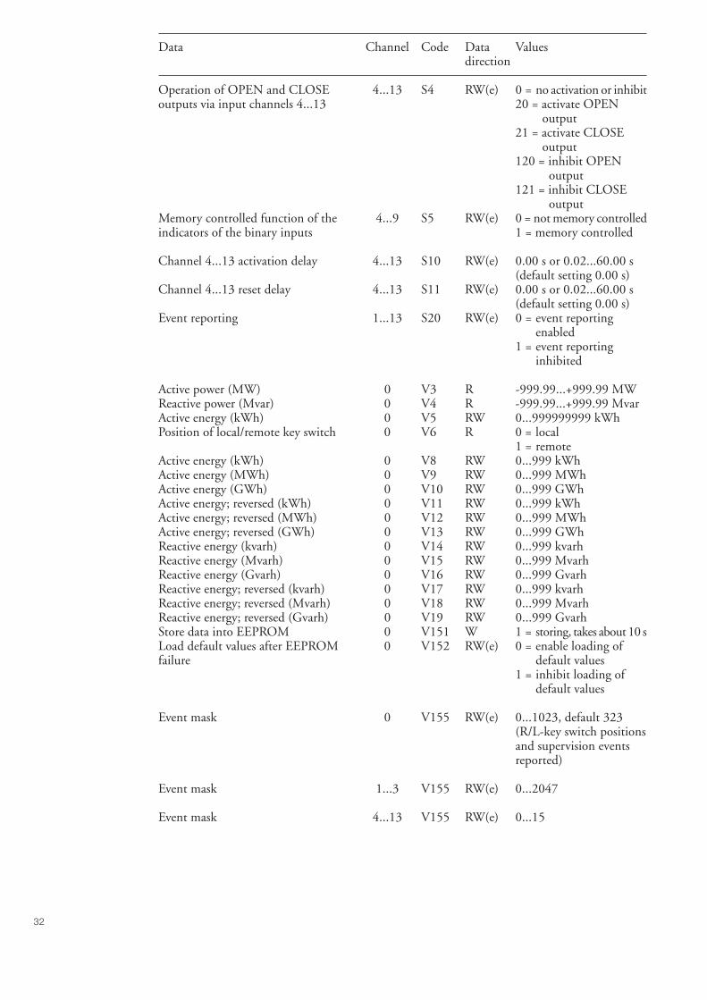
32
Data Channel Code Data Valuesdirection
Operation of OPEN and CLOSE 4...13 S4 RW(e) 0 = no activation or inhibitoutputs via input channels 4...13 20 = activate OPEN
output21 = activate CLOSE
output120 = inhibit OPEN
output121 = inhibit CLOSE
outputMemory controlled function of the 4...9 S5 RW(e) 0 = not memory controlledindicators of the binary inputs 1 = memory controlled
Channel 4...13 activation delay 4...13 S10 RW(e) 0.00 s or 0.02...60.00 s(default setting 0.00 s)
Channel 4...13 reset delay 4...13 S11 RW(e) 0.00 s or 0.02...60.00 s(default setting 0.00 s)
Event reporting 1...13 S20 RW(e) 0 = event reportingenabled
1 = event reportinginhibited
Active power (MW) 0 V3 R -999.99...+999.99 MWReactive power (Mvar) 0 V4 R -999.99...+999.99 MvarActive energy (kWh) 0 V5 RW 0...999999999 kWhPosition of local/remote key switch 0 V6 R 0 = local
1 = remoteActive energy (kWh) 0 V8 RW 0...999 kWhActive energy (MWh) 0 V9 RW 0...999 MWhActive energy (GWh) 0 V10 RW 0...999 GWhActive energy; reversed (kWh) 0 V11 RW 0...999 kWhActive energy; reversed (MWh) 0 V12 RW 0...999 MWhActive energy; reversed (GWh) 0 V13 RW 0...999 GWhReactive energy (kvarh) 0 V14 RW 0...999 kvarhReactive energy (Mvarh) 0 V15 RW 0...999 MvarhReactive energy (Gvarh) 0 V16 RW 0...999 GvarhReactive energy; reversed (kvarh) 0 V17 RW 0...999 kvarhReactive energy; reversed (Mvarh) 0 V18 RW 0...999 MvarhReactive energy; reversed (Gvarh) 0 V19 RW 0...999 GvarhStore data into EEPROM 0 V151 W 1 = storing, takes about 10 sLoad default values after EEPROM 0 V152 RW(e) 0 = enable loading offailure default values
1 = inhibit loading ofdefault values
Event mask 0 V155 RW(e) 0...1023, default 323(R/L-key switch positionsand supervision eventsreported)
Event mask 1...3 V155 RW(e) 0...2047
Event mask 4...13 V155 RW(e) 0...15
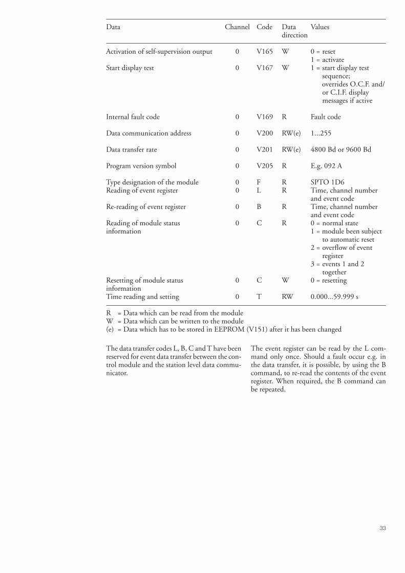
33
Data Channel Code Data Valuesdirection
Activation of self-supervision output 0 V165 W 0 = reset1 = activate
Start display test 0 V167 W 1 = start display testsequence;
overrides O.C.F. and/or C.I.F. displaymessages if active
Internal fault code 0 V169 R Fault code
Data communication address 0 V200 RW(e) 1...255
Data transfer rate 0 V201 RW(e) 4800 Bd or 9600 Bd
Program version symbol 0 V205 R E.g. 092 A
Type designation of the module 0 F R SPTO 1D6Reading of event register 0 L R Time, channel number
and event codeRe-reading of event register 0 B R Time, channel number
and event codeReading of module status 0 C R 0 = normal stateinformation 1 = module been subject
to automatic reset2 = overflow of event
register3 = events 1 and 2
togetherResetting of module status 0 C W 0 = resettinginformationTime reading and setting 0 T RW 0.000...59.999 s
R = Data which can be read from the moduleW = Data which can be written to the module(e) = Data which has to be stored in EEPROM (V151) after it has been changed
The data transfer codes L, B, C and T have beenreserved for event data transfer between the con-trol module and the station level data commu-nicator.
The event register can be read by the L com-mand only once. Should a fault occur e.g. inthe data transfer, it is possible, by using the Bcommand, to re-read the contents of the eventregister. When required, the B command canbe repeated.
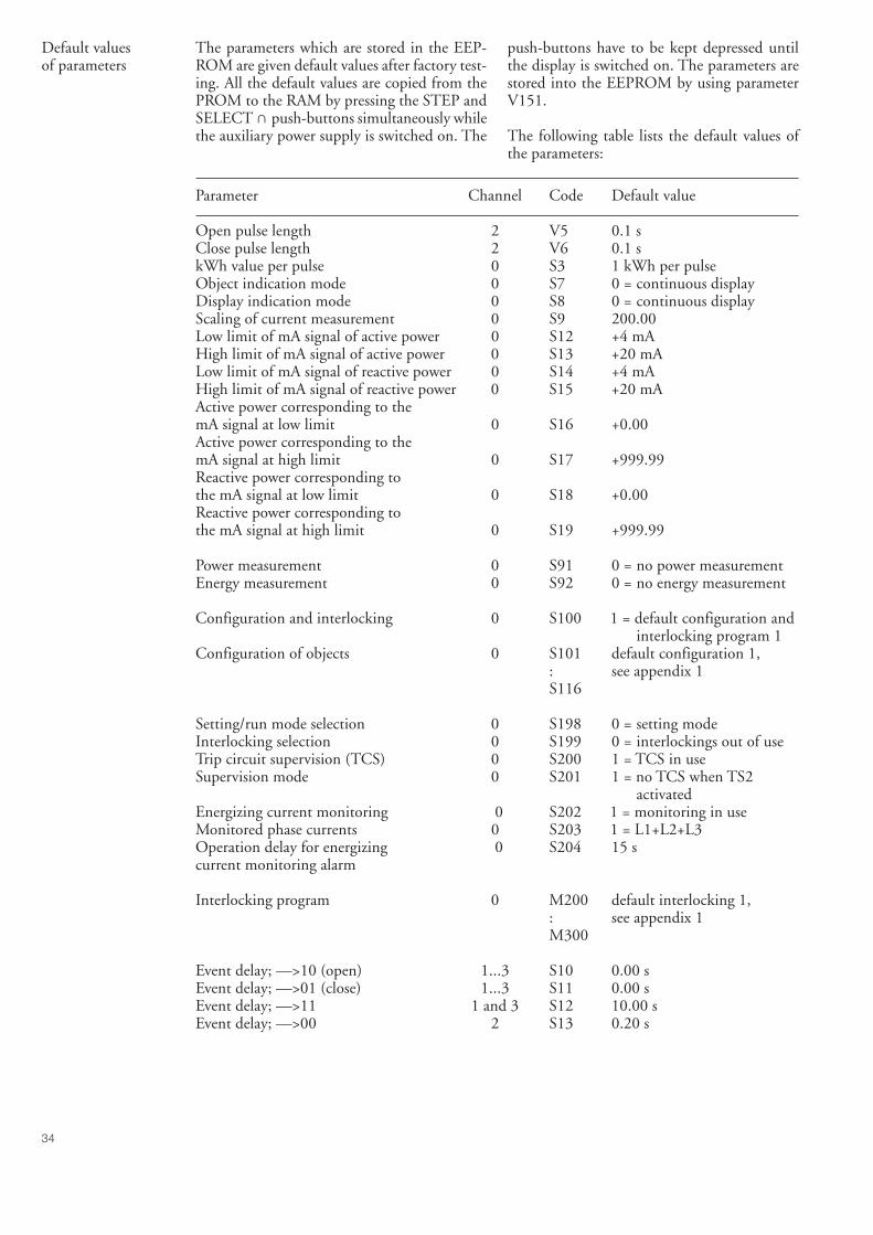
34
Default valuesof parameters
The parameters which are stored in the EEP-ROM are given default values after factory test-ing. All the default values are copied from thePROM to the RAM by pressing the STEP andSELECT ∩ push-buttons simultaneously whilethe auxiliary power supply is switched on. The
push-buttons have to be kept depressed untilthe display is switched on. The parameters arestored into the EEPROM by using parameterV151.
The following table lists the default values ofthe parameters:
Parameter Channel Code Default value
Open pulse length 2 V5 0.1 sClose pulse length 2 V6 0.1 skWh value per pulse 0 S3 1 kWh per pulseObject indication mode 0 S7 0 = continuous displayDisplay indication mode 0 S8 0 = continuous displayScaling of current measurement 0 S9 200.00Low limit of mA signal of active power 0 S12 +4 mAHigh limit of mA signal of active power 0 S13 +20 mALow limit of mA signal of reactive power 0 S14 +4 mAHigh limit of mA signal of reactive power 0 S15 +20 mAActive power corresponding to themA signal at low limit 0 S16 +0.00Active power corresponding to themA signal at high limit 0 S17 +999.99Reactive power corresponding tothe mA signal at low limit 0 S18 +0.00Reactive power corresponding tothe mA signal at high limit 0 S19 +999.99
Power measurement 0 S91 0 = no power measurementEnergy measurement 0 S92 0 = no energy measurement
Configuration and interlocking 0 S100 1 = default configuration andinterlocking program 1
Configuration of objects 0 S101 default configuration 1,: see appendix 1S116
Setting/run mode selection 0 S198 0 = setting modeInterlocking selection 0 S199 0 = interlockings out of useTrip circuit supervision (TCS) 0 S200 1 = TCS in useSupervision mode 0 S201 1 = no TCS when TS2
activatedEnergizing current monitoring 0 S202 1 = monitoring in useMonitored phase currents 0 S203 1 = L1+L2+L3Operation delay for energizing 0 S204 15 scurrent monitoring alarm
Interlocking program 0 M200 default interlocking 1,: see appendix 1M300
Event delay; —>10 (open) 1...3 S10 0.00 sEvent delay; —>01 (close) 1...3 S11 0.00 sEvent delay; —>11 1 and 3 S12 10.00 sEvent delay; —>00 2 S13 0.20 s

35
Parameter Channel Code Default value
Use of input 7 7 S1 0 = general modeOperation principle of 4...13 S2 1 = active at high stateinput channels 4...13Signal output activation byinput channels 4...13 4...13 S3 0 = no signal outputOperation of OPEN and CLOSEoutputs by input channels 4...13 4...13 S4 0 = no activation or inhibitMemory controlled function of the 4 ...13 S5 0 = not memory controlledindicators of the binary inputs
Activation delay 4...13 S10 0.00 sDeactivation delay 4...13 S11 0.00 s
Event reporting 1...13 S20 0 = event reporting enabled
Load default values after EEPROM 0 V152 1 = inhibitedfailureEvent mask 0 V155 323Event mask 1...3 V155 1875Event mask 4...13 V155 3
Data communication address 0 V200 99Data transfer rate 0 V201 9600 Bd
Technical data Control functions- status indication for maximum 3 objects, e.g. circuit breakers, disconnectors, earthing switches- configuration freely selectable by the user- remote or local control (open and close) for one object- output pulse length selectable, 0.1...100.0 s- 10 binary inputs for reading contact data other than status information- freely selectable feeder oriented interlocking system, the 3 status inputs plus 10 other binary
input channels and the L/R key switch state can be included- the 10 binary input channels can be used to control the OPEN and CLOSE outputs- four signal outputs which can be controlled by the 10 binary input channels
Measurements- measurement of three phase currents, measurement range 0...2.5 x In- accuracy of phase current measurement better than ±1 % of In- two mA inputs for measurement of active and reactive power- mA input range -20...+20 mA, can be limited by setting- accuracy of power measuring better than ±1 % of maximum value of measurement range- one pulse counter input for energy pulse counting, maximum input signal frequency 25 Hz- energy can also be calculated by integrating the measured active and reactive power value
over time- all measured values can be scaled as actual primary values- local display or remote reading of measured values
Supervision functions- energizing current circuit monitoring- trip circuit supervision- internal self-supervision of hardware and software in the control module
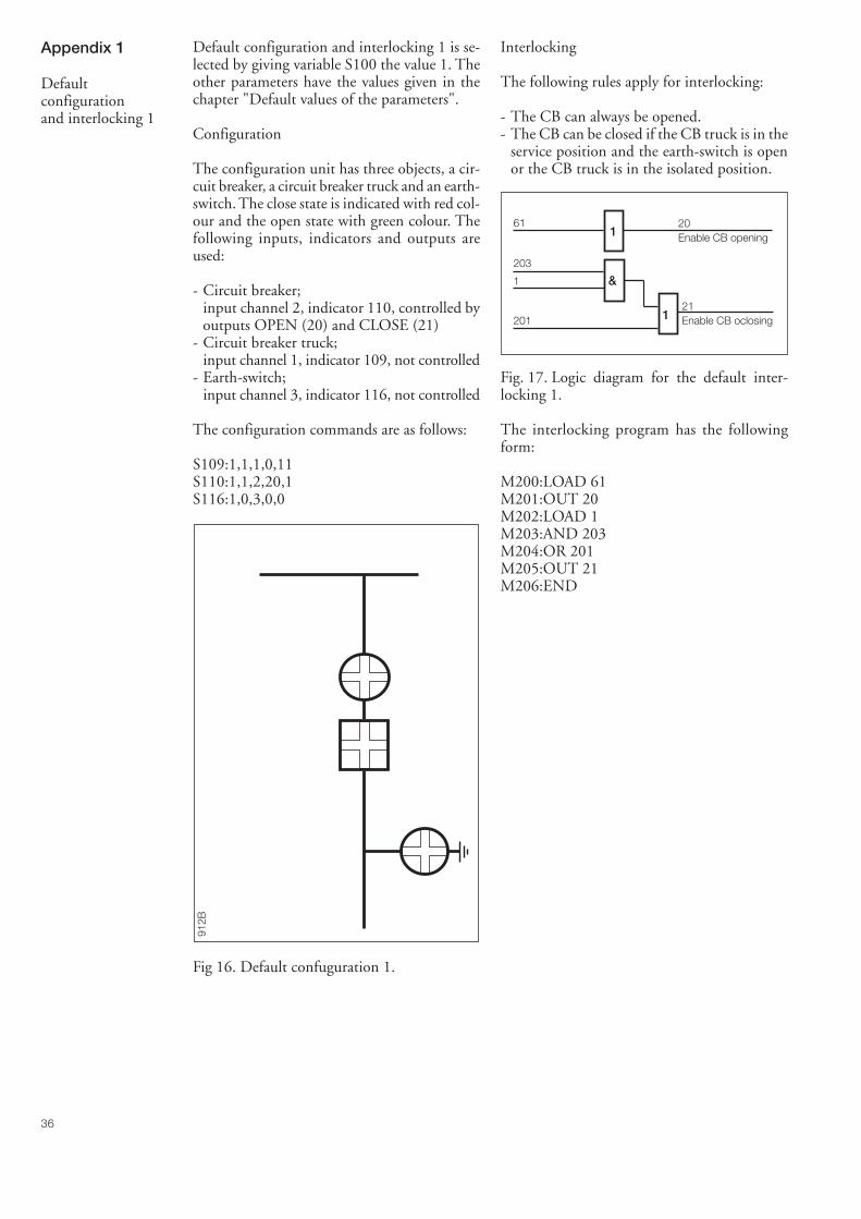
36
Appendix 1
Defaultconfigurationand interlocking 1
Default configuration and interlocking 1 is se-lected by giving variable S100 the value 1. Theother parameters have the values given in thechapter "Default values of the parameters".
Configuration
The configuration unit has three objects, a cir-cuit breaker, a circuit breaker truck and an earth-switch. The close state is indicated with red col-our and the open state with green colour. Thefollowing inputs, indicators and outputs areused:
- Circuit breaker;input channel 2, indicator 110, controlled byoutputs OPEN (20) and CLOSE (21)
- Circuit breaker truck;input channel 1, indicator 109, not controlled
- Earth-switch;input channel 3, indicator 116, not controlled
The configuration commands are as follows:
S109:1,1,1,0,11S110:1,1,2,20,1S116:1,0,3,0,0
Interlocking
The following rules apply for interlocking:
- The CB can always be opened.- The CB can be closed if the CB truck is in the
service position and the earth-switch is openor the CB truck is in the isolated position.
Fig. 17. Logic diagram for the default inter-locking 1.
The interlocking program has the followingform:
M200:LOAD 61M201:OUT 20M202:LOAD 1M203:AND 203M204:OR 201M205:OUT 21M206:END
1
&
1
61 20Enable CB opening
203
1
20121Enable CB oclosing
912B
Fig 16. Default confuguration 1.
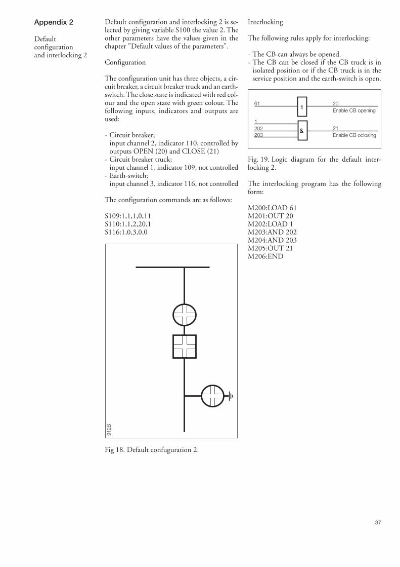
37
Appendix 2
Defaultconfigurationand interlocking 2
Default configuration and interlocking 2 is se-lected by giving variable S100 the value 2. Theother parameters have the values given in thechapter "Default values of the parameters".
Configuration
The configuration unit has three objects, a cir-cuit breaker, a circuit breaker truck and an earth-switch. The close state is indicated with red col-our and the open state with green colour. Thefollowing inputs, indicators and outputs areused:
- Circuit breaker;input channel 2, indicator 110, controlled byoutputs OPEN (20) and CLOSE (21)
- Circuit breaker truck;input channel 1, indicator 109, not controlled
- Earth-switch;input channel 3, indicator 116, not controlled
The configuration commands are as follows:
S109:1,1,1,0,11S110:1,1,2,20,1S116:1,0,3,0,0
Interlocking
The following rules apply for interlocking:
- The CB can always be opened.- The CB can be closed if the CB truck is in
isolated position or if the CB truck is in theservice position and the earth-switch is open.
Fig. 19. Logic diagram for the default inter-locking 2.
The interlocking program has the followingform:
M200:LOAD 61M201:OUT 20M202:LOAD 1M203:AND 202M204:AND 203M205:OUT 21M206:END
1
&
61 20Enable CB opening
203
1202 21
Enable CB oclosing
912B
Fig 18. Default confuguration 2.

38
Appendix 3
Defaultconfigurationand interlocking 10
Default configuration and interlocking 10 isselected by giving variable S100 the value 10.The other parameters have the values given inthe chapter "Default values of the parameters".
Configuration
The configuration has three objects, a circuitbreaker, a circuit breaker truck and an earth-switch. The close state is indicated with greencolour and the open state with red colour. Thisdefault is the same as default 1, but the coloursof the object indicators are reversed. The fol-lowing inputs, indicators and outputs are used:
- Circuit breaker;input channel 2, indicator 107, controlled byoutputs OPEN (20) and CLOSE (21)
- Circuit breaker truck;input channel 1, indicator 106, not controlled
- Earth-switch;input channel 3, indicator 104, not controlled
The configuration commands are as follows:
S106:1,1,1,0,11S107:1,1,2,20,1S104:1,0,3,0,0
Interlocking
The following rules apply for interlocking:
- The CB can always be opened.- The CB can be closed if if the CB truck is in
the service position and the earth-switch isopen or if the CB truck is in isolated position.
Fig. 21. Logic diagram for the default inter-locking 10.
The interlocking program has the followingform:
M200:LOAD 61M201:OUT 20M202:LOAD 1M203:AND 203M204:OR 201M205:OUT 21M206:END
954B
Fig. 20. Default configuration 10.
1
&
1
61 20Enable CB opening
203
1
20121Enable CB oclosing
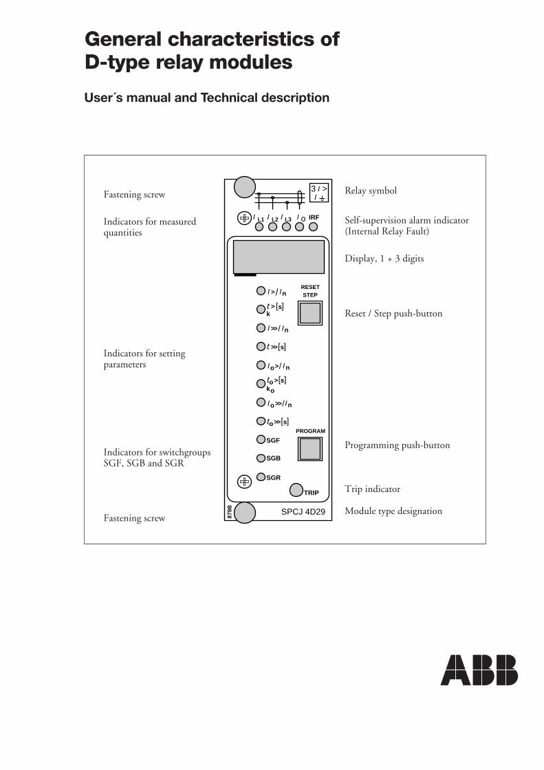
SGR
SGB
SGF
SPCJ 4D29
TRIP
PROGRAM
RESETSTEP
L1 L2 L3 o IRF
3 >I
IIII
> nI I/
ks>t [ ]
n>>I I/
s>>[ ]t
so >ko
[ ]t
no>I I/
s>>ot [ ]
n>>o I/I
879B
IRelay symbol
Self-supervision alarm indicator(Internal Relay Fault)
Display, 1 + 3 digits
Reset / Step push-button
Programming push-button
Trip indicator
Module type designation
Fastening screw
Indicators for measuredquantities
Indicators for settingparameters
Indicators for switchgroupsSGF, SGB and SGR
Fastening screw
General characteristics ofD-type relay modules
User´s manual and Technical description
2
General characteristicsof D type relay modules
Contents Front panel lay-out ......................................................................................................... 1Control push buttons ..................................................................................................... 3Display ........................................................................................................................... 3
Display main menu ................................................................................................... 3Display submenus ..................................................................................................... 3
Selector switchgroups SGF, SGB, SGR .......................................................................... 4Settings ........................................................................................................................... 4
Setting mode ............................................................................................................. 4Example 1: Setting of relay operation values .............................................................. 7Example 2: Setting of relay switchgroups................................................................... 9
Recorded information ................................................................................................... 11Trip test function ......................................................................................................... 12
Example 3: Forced activation of outputs ................................................................. 13Operation indicators ..................................................................................................... 15Fault codes .................................................................................................................... 15
1MRS 750066-MUM EN
Issued 95-04-12Version A (replaces 34 SPC 3 EN1)Checked JHApproved TK
Data subject to change without notice
3
Controlpush-buttons
The front panel of the relay module containstwo push buttons. The RESET / STEP pushbutton is used for resetting operation indicatorsand for stepping forward or backward in thedisplay main menu or submenus. The PRO-GRAM push button is used for moving from a
certain position in the main menu to the corre-sponding submenu, for entering the settingmode of a certain parameter and together withthe STEP push button for storing the set values.The different operations are described in thesubsequent paragraphs in this manual.
Display The measured and set values and the recordeddata are shown on the display of the protectionrelay module. The display consists of four digits.The three green digits to the right show themeasured, set or recorded value and the leftmostred digit shows the code number of the register.The measured or set value displayed is indicatedby the adjacent yellow LED indicator on thefront panel. When a recorded fault value is beingdisplayed the red digit shows the number of thecorresponding register. When the display func-tions as an operation indicator the red digitalone is shown.
When the auxiliary voltage of a protection relaymodule is switched on the module initially teststhe display by stepping through all the segmentsof the display for about 15 seconds. At first thecorresponding segments of all digits are lit oneby one clockwise, including the decimal points.Then the center segment of each digit is lit oneby one. The complete sequence is carried outtwice. When the test is finished the display turnsdark. The testing can be interrupted by pressingthe STEP push button. The protection func-tions of the relay module are alerted throughoutthe testing.
Display main menu Any data required during normal operation areaccessible in the main menu i.e. present meas-ured values, present setting values and recordedparameter values.
The data to be shown in the main menu aresequentially called up for display by means ofthe STEP push button. When the STEP pushbutton is pressed for about one second, thedisplay moves forward in the display sequence.When the push button is pressed for about 0.5seconds, the display moves backward in thedisplay sequence.
From a dark display only forward movement ispossible. When the STEP push button is pushedconstantly, the display continuously moves for-ward stopping for a while in the dark position.
Unless the display is switched off by stepping tothe dark point, it remains lit for about 5 minutesfrom the moment the STEP push button waslast pushed. After the 5 minutes' time-out thedispaly is switched off.
Display submenus Less important values and values not very oftenset are displayed in the submenus. The numberof submenus varies with different relay moduletypes. The submenus are presented in the de-scription of the concerned protection relaymodule.
A submenu is entered from the main menu bypressing the PROGRAM push button for aboutone second. When the push button is released,the red digit of the display starts flashing, indi-cating that a submenu has been entered. Goingfrom one submenu to another or back to themain menu follows the same principle as whenmoving from the main menu display to another;
the display moves forward when the STEP pushbutton is pushed for one second and backwardwhen it is pushed for 0.5 seconds. The mainmenu has been re-entered when the red displayturns dark.
When a submenu is entered from a main menuof a measured or set value indicated by a LEDindicator, the indicator remains lit and the ad-dress window of the display starts flashing. Asubmenu position is indicated by a flashing redaddress number alone on the dispaly withoutany lit set value LED indicator on the frontpanel.
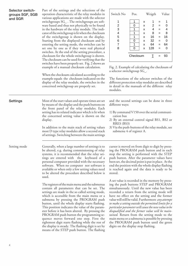
4
Selector switch-groups SGF, SGBand SGR
Part of the settings and the selections of theoperation characteristic of the relay modules invarious applications are made with the selectorswitchgroups SG_ . The switchgroups are soft-ware based and thus not physically to be foundin the hardware of the relay module. The indi-cator of the switchgroup is lit when the checksumof the switchgroup is shown on the display.Starting from the displayed checksum and byentering the setting mode, the switches can beset one by one as if they were real physicalswitches. At the end of the setting procedure, achecksum for the whole switchgroup is shown.The checksum can be used for verifying that theswitches have been properly set. Fig. 2 shows anexample of a manual checksum calculation.
When the checksum calculated according to theexample equals the checksum indicated on thedisplay of the relay module, the switches in theconcerned switchgroup are properly set.
Switch No Pos. Weigth Value
1 1 x 1 = 12 0 x 2 = 03 1 x 4 = 44 1 x 8 = 85 1 x 16 = 166 0 x 32 = 07 1 x 64 = 648 0 x 128 = 0
Checksum ∑ = 93
Fig. 2. Example of calculating the checksum ofa selector switchgroup SG_.
The functions of the selector switches of thedifferent protection relay modules are describedin detail in the manuals of the different relaymodules.
Settings Most of the start values and operate times are setby means of the display and the push buttons onthe front panel of the relay modules. Eachsetting has its related indicator which is lit whenthe concerned setting value is shown on thedisplay.
In addition to the main stack of setting valuesmost D type relay modules allow a second stackof settings. Switching between the main settings
and the second settings can be done in threedifferent ways:
1) By command V150 over the serial communi-cation bus
2) By an external control signal BS1, BS2 orRRES (BS3)
3) Via the push-buttons of the relay module, seesubmenu 4 of register A.
Setting mode Generally, when a large number of settings is tobe altered, e.g. during commissioning of relaysystems, it is recommended that the relay set-tings are entered with the keyboard of apersonal computer provided with the necessarysoftware. When no computer nor software isavailable or when only a few setting values needto be altered the procedure described below isused.
The registers of the main menu and the submenuscontain all parameters that can be set. Thesettings are made in the so called setting mode,which is accessible from the main menu or asubmenu by pressing the PROGRAM pushbutton, until the whole display starts flashing.This position indicates the value of the param-eter before it has been altered. By pressing thePROGRAM push button the programming se-quence moves forward one step. First therightmost digit starts flashing while the rest ofthe display is steady. The flashing digit is set bymeans of the STEP push button. The flashing
cursor is moved on from digit to digit by press-ing the PROGRAM push button and in eachstop the setting is performed with the STEPpush button. After the parameter values havebeen set, the decimal point is put in place. At theend the position with the whole display flashingis reached again and the data is ready to bestored.
A set value is recorded in the memory by press-ing the push buttons STEP and PROGRAMsimultaneously. Until the new value has beenrecorded a return from the setting mode willhave no effect on the setting and the formervalue will still be valid. Furthermore any attemptto make a setting outside the permitted limits for aparticular parameter will cause the new value to bedisqualified and the former value will be main-tained. Return from the setting mode to themain menu or a submenu is possible by pressingthe PROGRAM push button until the greendigits on the display stop flashing.
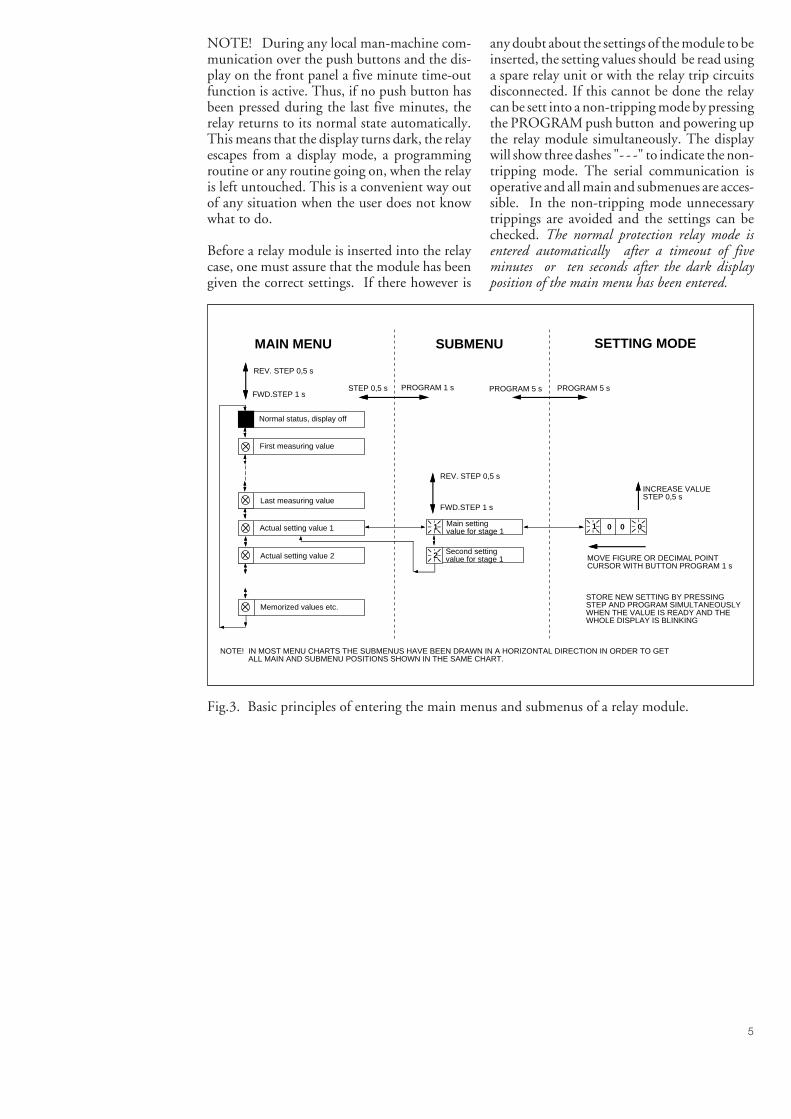
5
NOTE! During any local man-machine com-munication over the push buttons and the dis-play on the front panel a five minute time-outfunction is active. Thus, if no push button hasbeen pressed during the last five minutes, therelay returns to its normal state automatically.This means that the display turns dark, the relayescapes from a display mode, a programmingroutine or any routine going on, when the relayis left untouched. This is a convenient way outof any situation when the user does not knowwhat to do.
Before a relay module is inserted into the relaycase, one must assure that the module has beengiven the correct settings. If there however is
any doubt about the settings of the module to beinserted, the setting values should be read usinga spare relay unit or with the relay trip circuitsdisconnected. If this cannot be done the relaycan be sett into a non-tripping mode by pressingthe PROGRAM push button and powering upthe relay module simultaneously. The displaywill show three dashes "- - -" to indicate the non-tripping mode. The serial communication isoperative and all main and submenues are acces-sible. In the non-tripping mode unnecessarytrippings are avoided and the settings can bechecked. The normal protection relay mode isentered automatically after a timeout of fiveminutes or ten seconds after the dark displayposition of the main menu has been entered.
Normal status, display off
First measuring value
Last measuring value
Memorized values etc.
Actual setting value 1
SUBMENUMAIN MENU SETTING MODE
Second setting value for stage 12
1 Main setting value for stage 1
1 0 0 0
INCREASE VALUESTEP 0,5 s
MOVE FIGURE OR DECIMAL POINT CURSOR WITH BUTTON PROGRAM 1 s
STORE NEW SETTING BY PRESSING STEP AND PROGRAM SIMULTANEOUSLY WHEN THE VALUE IS READY AND THE WHOLE DISPLAY IS BLINKING
Actual setting value 2
FWD.STEP 1 s
REV. STEP 0,5 s
FWD.STEP 1 s
REV. STEP 0,5 s
NOTE! IN MOST MENU CHARTS THE SUBMENUS HAVE BEEN DRAWN IN A HORIZONTAL DIRECTION IN ORDER TO GET ALL MAIN AND SUBMENU POSITIONS SHOWN IN THE SAME CHART.
STEP 0,5 s PROGRAM 1 s PROGRAM 5 s PROGRAM 5 s
Fig.3. Basic principles of entering the main menus and submenus of a relay module.
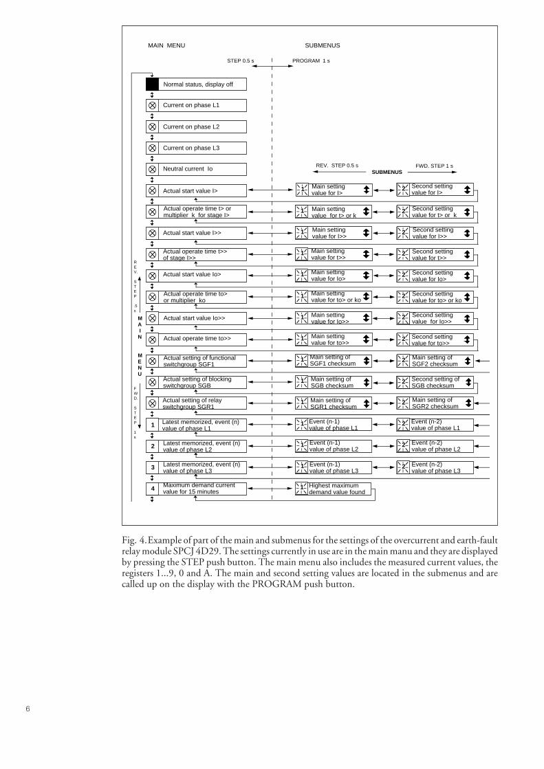
6
Normal status, display off
Current on phase L1
Current on phase L2
Current on phase L3
Neutral current Io
Maximum demand currentvalue for 15 minutes4
Second settingvalue for t> or k
Actual operate time t> or multiplier k for stage I>
21
Second settingvalue for I>> Actual start value I>> 21
Second settingvalue for t>>
Actual operate time t>> of stage I>>
21
Second setting value for Io>
Actual start value Io> 21
Second settingvalue for to> or ko
Actual operate time to>or multiplier ko
21
Second setting value for Io>> Actual start value Io>> 21
Second setting value for to>>
Actual operate time to>> 21
Main setting of SGF1 checksum
Actual setting of functionalswitchgroup SGF1
21
Actual setting of blockingswitchgroup SGB
1 Main setting of SGB checksum
Actual setting of relayswitchgroup SGR1
1 Main setting of SGR1 checksum
2
Event (n-1) value of phase L1
Event (n-2) value of phase L1
Latest memorized, event (n)value of phase L11 1 2
Event (n-1) value of phase L2
Event (n-2) value of phase L2
Latest memorized, event (n) value of phase L22 1 2
Event (n-1) value of phase L3
Event (n-2) value of phase L3
Latest memorized, event (n)value of phase L33 1 2
Main settingvalue for t> or k
Main settingvalue for I>>
Main settingvalue for t>>
Main setting value for Io>
Main settingvalue for to> or ko
Main setting value for Io>>
Main setting value for to>>
Second setting of SGB checksum
2
Second setting value for I>
21 Main setting value for I> Actual start value I>
SUBMENUSFWD. STEP 1 sREV. STEP 0.5 s
MA IN
MENU
REV.
STEP
.5s
FWD.
STEP
1s
MAIN MENU SUBMENUS
STEP 0.5 s PROGRAM 1 s
Highest maximum demand value found
1
Main setting of SGF2 checksum
Main setting of SGR2 checksum
Fig. 4.Example of part of the main and submenus for the settings of the overcurrent and earth-faultrelay module SPCJ 4D29. The settings currently in use are in the main manu and they are displayedby pressing the STEP push button. The main menu also includes the measured current values, theregisters 1...9, 0 and A. The main and second setting values are located in the submenus and arecalled up on the display with the PROGRAM push button.
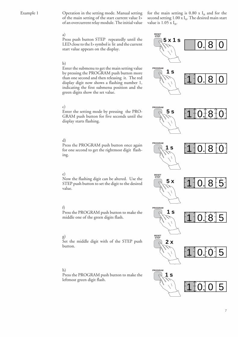
7
Example 1 Operation in the setting mode. Manual settingof the main setting of the start current value I>of an overcurrent relay module. The initial value
a)Press push button STEP repeatedly until theLED close to the I> symbol is lit and the currentstart value appears on the display.
b)Enter the submenu to get the main setting valueby pressing the PROGRAM push button morethan one second and then releasing it. The reddisplay digit now shows a flashing number 1,indicating the first submenu position and thegreen digits show the set value.
c)Enter the setting mode by pressing the PRO-GRAM push button for five seconds until thedisplay starts flashing.
d)Press the PROGRAM push button once againfor one second to get the rightmost digit flash-ing.
e)Now the flashing digit can be altered. Use theSTEP push button to set the digit to the desiredvalue.
f)Press the PROGRAM push button to make themiddle one of the green digits flash.
g)Set the middle digit with of the STEP pushbutton.
h)Press the PROGRAM push button to make theleftmost green digit flash.
for the main setting is 0.80 x In and for thesecond setting 1.00 x In. The desired main startvalue is 1.05 x In.
5 x 1 s
1 s
5 s
1 s
5 x
1 s
2 x
1 s
0. 8 0
1 0. 8 0
1 0. 8 0
1 0. 8 0
1 0. 8 5
1 0. 8 5
1 0. 0 5
1 0. 0 5
RESET STEP
PROGRAM
PROGRAM
PROGRAM
RESET STEP
RESET STEP
PROGRAM
PROGRAM
8
1 s
0 x
1 s
0 x
1 s
5 s
1 1. 0 5
1 1. 0 5
1 1. 0 5
1 1. 0 5
1 - - -
1 1. 0 5
2 1. 0 0
i)Set the digit with the STEP push button.
j)Press the PROGRAM push button to make thedecimal point flash.
k)If needed, move the decimal point with theSTEP push button.
l)Press the PROGRAM push button to make thewhole display flash. In this position, corre-sponding to position c) above, one can see thenew value before it is recorded. If the valueneeds changing, use the PROGRAM push but-ton to alter the value.
m)When the new value has been corrected, recordit in the memory of the relay module by pressingthe PROGRAM and STEP push buttons simul-taneously. At the moment the information en-ters the memory, the green dashes flash once inthe display, i.e. 1 - - -.
n)Recording of the new value automatically initi-ates a return from the setting mode to thenormal submenu. Without recording one canleave the setting mode any time by pressing thePROGRAM push button for about five sec-onds, until the green display digits stop flashing.
o)If the second setting is to be altered, entersubmenu position 2 of the setting I> by pressingthe STEP push button for approx. one second.The flashing position indicator 1 will then bereplaced by a flashing number 2 which indicatesthat the setting shown on the display is thesecond setting for I>.
Enter the setting mode as in step c) and proceedin the same way. After recording of the re-quested values return to the main menu isobtained by pressing the STEP push button
RESET STEP
PROGRAM
RESET STEP
PROGRAM
RESET STEP
PROGRAM
PROGRAM
RESET STEP
until the first digit is switched off. The LED stillshows that one is in the I> position and thedisplay shows the new setting value currently inuse by the relay module.

9
Example 2
5 s
1 x
1 s
1 x
1 s
Operation in the setting mode. Manual settingof the main setting of the checksum for theswitchgroup SGF1 of a relay module. The initialvalue for the checksum is 000 and the switches
SGF1/1and SGF1/3 are to be set in position 1.This means that a checksum of 005 should bethe final result.
n x 1 s
1 s
a)Press push button STEP until the LED close tothe SGF symbol is lit and the checksum appearson the display.
b)Enter the submenu to get the main checksum ofSGF1 by pressing the PROGRAM push buttonfor more than one second and then releasing it.The red display now shows a flashing number 1indicating the first submenu position and thegreen digits show the checksum.
c)Enter the setting mode by pressing the PRO-GRAM push button for five seconds until thedisplay starts flashing.
d)Press the PROGRAM push button once againto get the first switch position. The first digit ofthe display now shows the switch number. Theposition of the switch is shown by the rightmostdigit.
e)The switch position can now be toggled be-tween 1 and 0 by means of the STEP pushbutton and it is left in the requested position 1.
f)When switch number 1 is in the requestedposition, switch number 2 is called up by press-ing the PROGRAM push button for one sec-ond. As in step e), the switch position can bealtered by using the STEP push button. As thedesired setting for SGF1/2 is 0 the switch is leftin the 0 position.
g)Switch SGF1/3 is called up as in step f) bypressing the PROGRAM push button for aboutone second.
0 0 0
1 0 0 0
1 0 0 0
1 1 0
1 1 1
1 2 0
1 3 0
RESET STEP
PROGRAM
PROGRAM
PROGRAM
RESET STEP
PROGRAM
PROGRAM
10
1 x
n x 1 s
5 s
5 x 1 s
1 0 0 5
1 - - -
1 0 0 5
0 0 5
1 3 1h)The switch position is altered to the desiredposition 1 by pressing the STEP push buttononce.
i)Using the same procedure the switches SGF 1/4...8 are called up and, according to the exam-ple, left in position 0.
j)In the final setting mode position, correspond-ing to step c), the checksum based on the setswitch positions is shown.
k)If the correct checksum has been obtained, it isrecorded in the memory by pressing the pushbuttons PROGRAM and STEP simultaneously.At the moment the information enters thememory, the green dashes flash in the display,i.e.1 - - -. If the checksum is incorrect, thesetting of the separate switches is repeated usingthe PROGRAM and STEP push buttons start-ing from step d).
l)Recording the new value automatically initiatesa return from the setting mode to the normalmenu. Without recording one can leave thesetting mode any time by pressing the PRO-GRAM push button for about five seconds,until the green display digits stop flashing.
m)After recording the desired values return to themain menu is obtained by pressing the STEPpush button until the first digit is turned off.The LED indicator SGF still shows that one isin the SGF position and that the display showsthe new checksum for SGF1 currently in use bythe relay module.
RESET STEP
PROGRAM
RESET STEP
PROGRAM
PROGRAM
RESET STEP
11
Recordedinformation
The parameter values measured at the momentwhen a fault occurs or at the trip instant arerecorded in the registers. The recorded data,except for some parameters, are set to zero bypressing the push buttons STEP and PRO-GRAM simultaneously. The data in normalregisters are erased if the auxiliary voltage supplyto the relay is interrupted, only the set values andcertain other essential parameters are maintainedin non-volatile registers during a voltage failure.
The number of registers varies with differentrelay module types. The functions of the regis-ters are illustrated in the descriptions of thedifferent relay modules. Additionally, the sys-tem front panel of the relay contains a simplifiedlist of the data recorded by the various relaymodules of the protection relay.
All D type relay modules are provided with twogeneral registers: register 0 and register A.
Register 0 contains, in coded form, the informa-tion about e.g. external blocking signals, statusinformation and other signals. The codes areexplained in the manuals of the different relaymodules.
Register A contains the address code of the relaymodul which is reqiured by the serial communi-cation system.
Submenu 1 of register A contains the data trans-fer rate value, expressed in kilobaud, of the serialcommunication.
Submenu 2 of register A contains a bus commu-nication monitor for the SPAbus. If the protec-tion relay, which contains the relay module, islinked to a system including a contol datacommunicatoe, for instance SRIO 1000M andthe data communication system is operating,the counter reading of the monitor will be zero.Otherwise the digits 1...255 are continuouslyscrolling in the monitor.
Submenu 3 contains the password required forchanging the remote settings. The address code,the data transfer rate of the serial communica-tion and the password can be set manually or viathe serial communication bus. For manual set-ting see example 1.
The default value is 001 for the address code, 9.6kilobaud for the data transfer rate and 001 forthe password.
In order to secure the setting values, all settingsare recorded in two separate memory bankswithin the non-volatile memory. Each bank iscomplete with its own checksum test to verifythe condition of the memory contents. If, forsome reason, the contents of one bank isdisturbed, all settings are taken from the otherbank and the contents from here is transferred tothe faulty memory region, all while the relay isin full operation condition. If both memorybanks are simultaneously damaged the relay willbe be set out of operation, and an alarm signalwill be given over the serial port and the IRFoutput relay
12
Trip test function Register 0 also provides access to a trip testfunction, which allows the output signals of therelay module to be activated one by one. If theauxiliary relay module of the protection assem-bly is in place, the auxiliary relays then willoperate one by one during the testing.
When pressing the PROGRAM push buttonfor about five seconds, the green digits to theright start flashing indicating that the relaymodule is in the test position. The indicators ofthe settings indicate by flashing which outputsignal can be activated. The required outputfunction is selected by pressing the PROGRAMpush button for about one second.
The indicators of the setting quantities refer tothe following output signals:
Setting I> Starting of stage I>Setting t> Tripping of stage I>Setting I>> Starting of stage I>>Setting t>> Tripping of stage I>>etc.No indication Self-supervision IRF
The selected starting or tripping is activated bysimultaneous pressing of the push buttonsSTEP and PROGRAM. The signal remainsactivated as long as the two push butttons arepressed. The effect on the output relays dependson the configuration of the output relay matrixswitches.
The self-supervision output is activated by press-ing the STEP push button 1 second when nosetting indicator is flashing. The IRF output isactivated in about 1 second after pressing of theSTEP push button.
The signals are selected in the order illustrated inFig. 4.
REGISTER 0I> START I> TRIP I» START I» TRIP Io> START Io> TRIP Io»START Io» TRIP
PROGRAM 5 s
PROGRAM 1 s
PROGRAM 1 s
PROGRAM 1 s
PROGRAM 1 s
PROGRAM 1 s
PROGRAM 1 s
PROGRAM 1 s
PROGRAM 1 s
STEP &PROGRAM
STEP &PROGRAM
STEP &PROGRAM
STEP &PROGRAM
STEP &PROGRAM
STEP &PROGRAM
STEP &PROGRAM
STEP &PROGRAM
I»t»
I>t>
Io> to>Io»
to»
IRF
STEP
PROGRAM 1 s
Fig. 5.Sequence order for the selection of output signals in the Trip test mode
If, for instance, the indicator of the setting t> isflashing, and the push buttons STEP and PRO-GRAM are being pressed, the trip signal fromthe low-set overcurrent stage is activated. Re-turn to the main menu is possible at any stage ofthe trip test sequence scheme, by pressing thePROGRAM push button for about five sec-onds.
Note!The effect on the output relays then depends onthe configuration of the output relay matrixswitchgroups SGR 1...3.
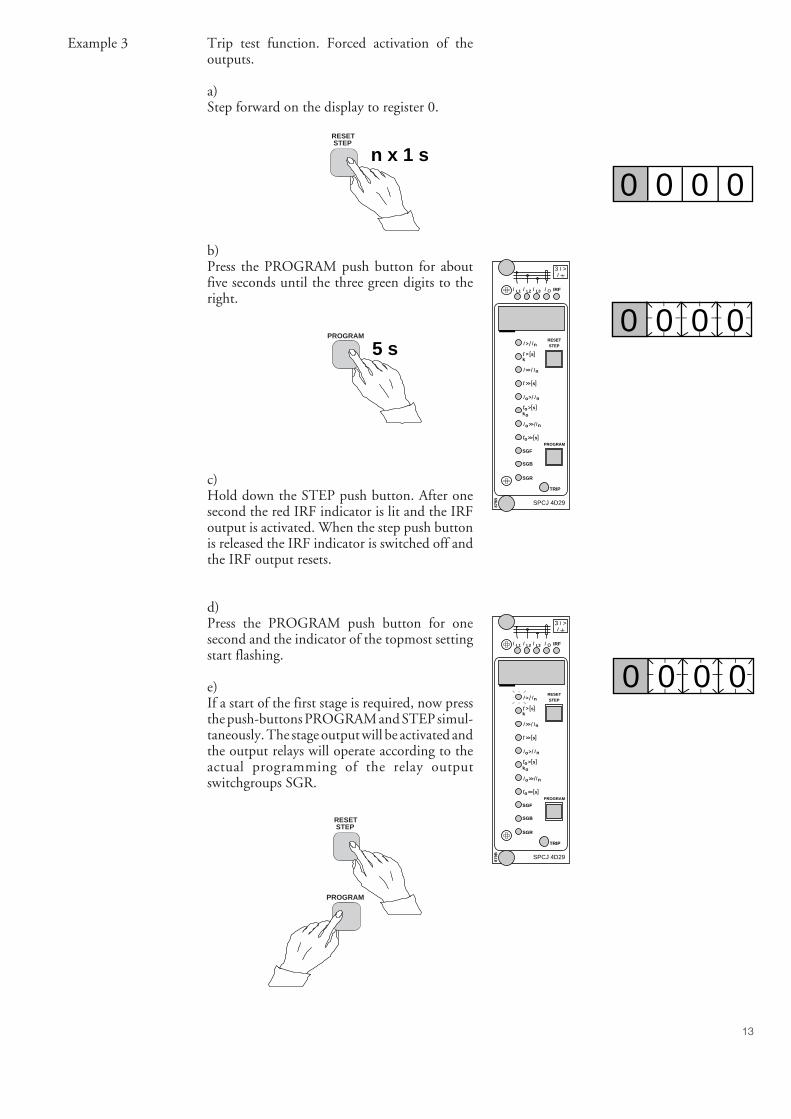
13
SGR
SGB
SGF
SPCJ 4D29
TRIP
PROGRAM
RESETSTEP
L1 L2 L3 o IRF
3 >I
IIII
> nI I/
ks>t [ ]
n>>I I/
s>>[ ]t
so >ko
[ ]t
no>I I/
s>>ot [ ]
n>>o I/I
879B
I
Example 3
n x 1 s
0 0 0 0
5 s0 0 0 0
Trip test function. Forced activation of theoutputs.
a)Step forward on the display to register 0.
b)Press the PROGRAM push button for aboutfive seconds until the three green digits to theright.
c)Hold down the STEP push button. After onesecond the red IRF indicator is lit and the IRFoutput is activated. When the step push buttonis released the IRF indicator is switched off andthe IRF output resets.
d)Press the PROGRAM push button for onesecond and the indicator of the topmost settingstart flashing.
e)If a start of the first stage is required, now pressthe push-buttons PROGRAM and STEP simul-taneously. The stage output will be activated andthe output relays will operate according to theactual programming of the relay outputswitchgroups SGR.
0 0 0 0
RESET STEP
PROGRAM
RESET STEP
PROGRAM
SGR
SGB
SGF
SPCJ 4D29
TRIP
PROGRAM
RESETSTEP
L1 L2 L3 o IRF
3 >I
IIII
> nI I/
ks>t [ ]
n>>I I/
s>>[ ]t
so >ko
[ ]t
no>I I/
s>>ot [ ]
n>>o I/I
879B
I
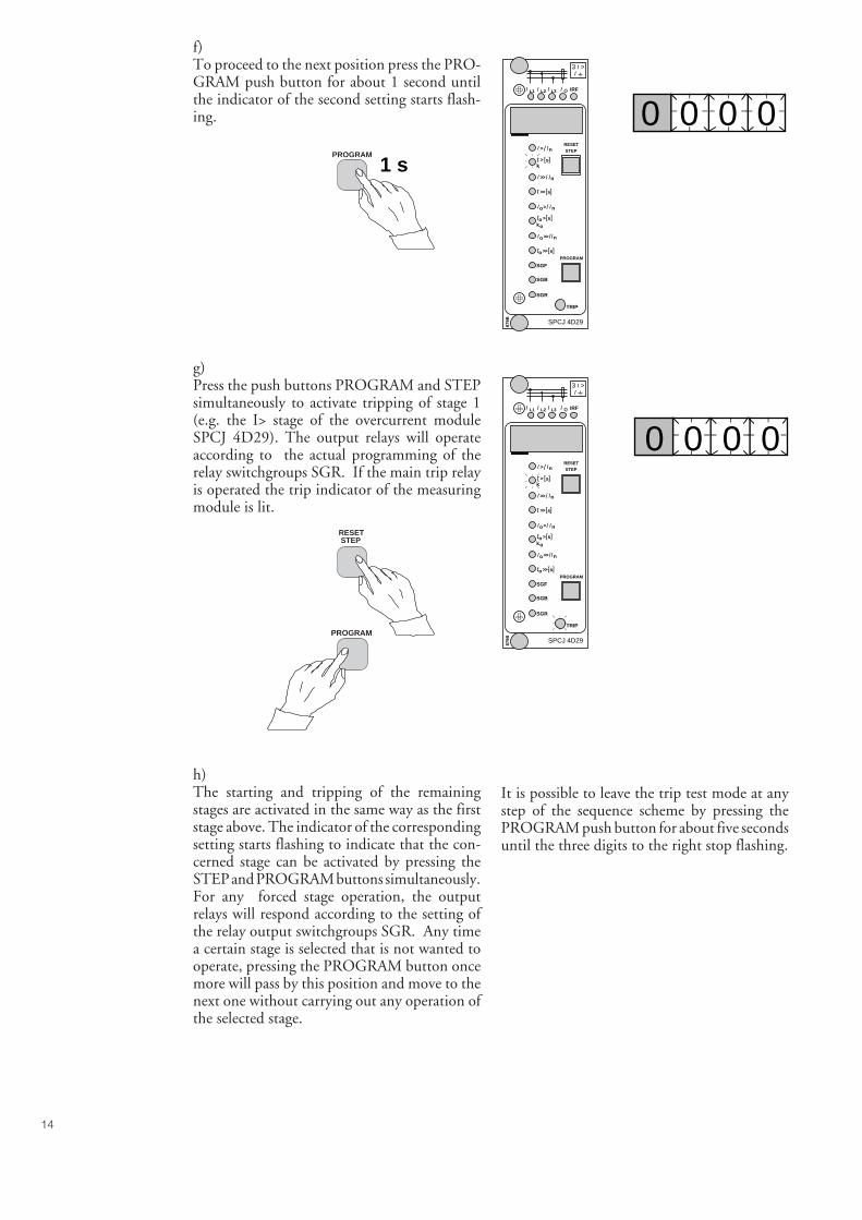
14
SGR
SGB
SGF
SPCJ 4D29
TRIP
PROGRAM
RESETSTEP
L1 L2 L3 o IRF
3 >I
IIII
> nI I/
ks>t [ ]
n>>I I/
s>>[ ]t
so >ko
[ ]t
no>I I/
s>>ot [ ]
n>>o I/I
879B
I
SGR
SGB
SGF
SPCJ 4D29
TRIP
PROGRAM
RESETSTEP
L1 L2 L3 o IRF
3 >I
IIII
> nI I/
ks>t [ ]
n>>I I/
s>>[ ]t
so >ko
[ ]t
no>I I/
s>>ot [ ]
n>>o I/I
879B
I
0 0 0 0
0 0 0 0
f)To proceed to the next position press the PRO-GRAM push button for about 1 second untilthe indicator of the second setting starts flash-ing.
g)Press the push buttons PROGRAM and STEPsimultaneously to activate tripping of stage 1(e.g. the I> stage of the overcurrent moduleSPCJ 4D29). The output relays will operateaccording to the actual programming of therelay switchgroups SGR. If the main trip relayis operated the trip indicator of the measuringmodule is lit.
h)The starting and tripping of the remainingstages are activated in the same way as the firststage above. The indicator of the correspondingsetting starts flashing to indicate that the con-cerned stage can be activated by pressing theSTEP and PROGRAM buttons simultaneously.For any forced stage operation, the outputrelays will respond according to the setting ofthe relay output switchgroups SGR. Any timea certain stage is selected that is not wanted tooperate, pressing the PROGRAM button oncemore will pass by this position and move to thenext one without carrying out any operation ofthe selected stage.
It is possible to leave the trip test mode at anystep of the sequence scheme by pressing thePROGRAM push button for about five secondsuntil the three digits to the right stop flashing.
PROGRAM
1 s
RESET STEP
PROGRAM
15
Operationindication
Fault codes
A relay module is provided with a multiple ofseparate operation stages, each with its ownoperation indicator shown on the display and acommon trip indicator on the lower part of thefront plate of the relay module.
The starting of a relay stage is indicated with onenumber which changes to another number whenthe stage operates. The indicator remains glow-ing although the operation stage resets. The
In addition to the protection functions the relaymodule is provided with a self-supervision sys-tem which continuously supervises the functionof the microprocessor, its program executionand the electronics.
Shortly after the self-supervision system detectsa permanent fault in the relay module, the redIRF indicator on the front panel is lit . At thesame time the module puts forward a controlsignal to the output relay of the self-supervisionsystem of the protection relay.
In most fault situations a fault code, indicatingthe nature of the fault, appears on the display of
the module. The fault code, which consists of ared figure "1" and a three digit green codenumber, cannot be removed from the display byresetting. When a fault occurs, the fault codeshould be recorded and stated when service isordered. When in a fault mode, the normalrelay menus are operative, i.e. all setting valuesand measured values can be accessed althoughthe relay operation is inhibited. The serial com-munication is also operative making it possibleto access the relay information also from aremote site. The internal relay fault code shownon the display remains active until the internalfault possibly disappears and can also be re-motely read out as variable V 169.
indicator is reset by means of the RESET pushbutton of the relay module. An unreset opera-tion indicator does not affect the function of theprotection relay module.
In certain cases the function of the operationindicators may deviate from the above princi-ples. This is described in detail in the descrip-tions of the separate modules.

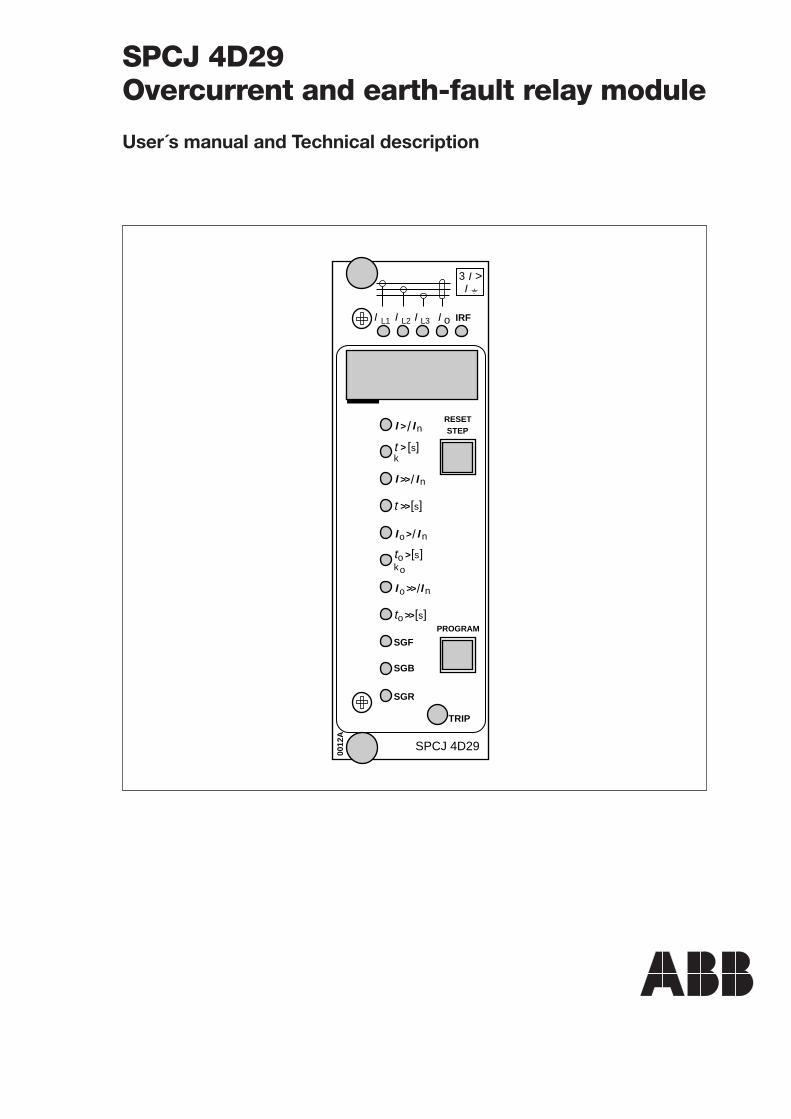
[
SGR
SGB
SGF
SPCJ 4D29
TRIP
PROGRAM
RESETSTEP
L1 L2 L3 o IRF
3 >II
IIII
> nI I/
ks>t ]
n>>I I/
s>>[ ]t
so >ko
[ ]t
no >I I/
s>>ot [ ]
n>>o I/I
0012
A
SPCJ 4D29Overcurrent and earth-fault relay module
User´s manual and Technical description
2
Features Low-set phase overcurrent stage I> with definitetime or inverse time characteristic
High-set phase overcurrent stage I>> with in-stantaneous function or definite time character-istic
Low-set earth-fault stage I0> with definite timeor inverse time characteristic
High-set earth-fault stage I0>> with definitetime characteristic
Six time/current curve sets at inverse time char-acteristic of the overcurrent stage I> and theearth-fault stage I0>
Digital display of measured and set values anddata sets recorded at the moment of relay opera-tion
Parametrization of the module by push-buttonson the front panel or via the serial port using aportable PC and a suitable software
Continuous hardware and software supervisionincluding auto-diagnosis
SPCJ 4D29Combined overcurrent
and earth-fault relaymodule
Features .......................................................................................................................... 2Description of function .................................................................................................. 3Block diagram................................................................................................................. 5Front panel ..................................................................................................................... 6Start and operation indicators ......................................................................................... 7Settings ........................................................................................................................... 8Selector switches ............................................................................................................. 9Measured data .............................................................................................................. 13Recorded information ................................................................................................... 14Menu and register chart ................................................................................................ 16Time/current characteristic (modified 2002-05) ............................................................ 18Technical data .............................................................................................................. 26Serial communication parameters ................................................................................. 27Fault codes .................................................................................................................... 34
Contents
1MRS 750119-MUM EN
Issued 1996-06-17Modified 2002-05-15Version C (replaces 34 SPCJ 8 EN1)Checked MKApproved OL
Data subject to change without notice
3
Description offunction
Phase overcurrentunit
The phase overcurrent unit of the relay moduleSPCJ 4D29 is designed for single-phase, two-phase or three-phase overcurrent protection. Itincludes two overcurrent stages, i.e. a low-setovercurrent stage I> and a high-set overcurrentstage I>>.
The low-set or high-set phase overcurrent stagestarts if the current on one or several of thephases exceeds the set start current value of thestage concerned. When the stage starts it gen-erates a start signal SS1 or TS1 and simultane-ously the digital display on the front panelindicates starting. If the overcurrent situationlasts long enough to exceed the set operatetime, the stage operates and generates a tripsignal TS2. At the same time the operationindicator is lit with red light. The red operationindicator remains lit although the stage resets.The indicator is reset by pushing the RESETpush-button. By proper configuration of theoutput relay switchgroups an additional auxil-iary trip signal TS1 can be obtained.
The operation of the low-set phase overcurrentstage I> or the high-set phase overcurrent stageI>> can be blocked by routing a blocking signalBS to the unit. The blocking configuration isset with switchgroup SGB.
The operation of the low-set phase overcurrentstage can be based on definite time or inversetime characteristic. The operation characteris-tic is selected with the SGF1/1…3 switches.At definite time operation characteristic theoperate time t> is set in seconds within therange, 0.05...300 s. When the inverse timeoperation characteristic (IDMT) is selected,four internationally standardized and two com-plementary time/current curves are available.The selector switches SGF1/1...3 are also usedfor selecting the desired operation characteris-tic.
Note!The maximum continuous current carryingcapacity of the energizing inputs is 4 x In,which must be observed when relay settings arecalculated.
Note!At inverse time characteristic the effective set-ting range of the low-set overcurrent stage is0.5…2.5 x In, although start current settingswithin the range 2.5…5.0 x In can be set on therelay. At inverse time characteristic any startcurrent setting above 2.5 x In of the low-setstage will be regarded as being equal to 2.5 x In.
Note!The operation of the low-set stage based oninverse time characteristic will be blocked bystarting of the high-set stage. Then the operatetime of the overcurrent unit is determined bythe set operate time of the high-set stage at heavyfault currents.
The setting range of the operate time t>> of thehigh-set phase overcurrent stage is 0.04...300 s.
The operate signal of the two overcurrent stagesis provided with a latching feature (switchSGB/6) which means that the operate signalTS2 is kept high after an operation, althoughthe overcurrent stage resets. The latched TS2signal is reset by pushing the RESET and PRO-GRAM push-buttons simultaneously or via theserial port using the command V101, see alsochapter "Selector switches".
The set start current value I>> of the high-setphase overcurrent stage can be doubled auto-matically on connection of the protected objectto the network, i.e. at starting. In this way thestart current of the high-set phase overcurrentstage can be given a lower value than the level ofthe connection inrush current. The automaticdoubling function is selected with switch SGF1/5.The starting, which activates the doubling func-tion, is defined as a situation where the phasecurrents rise from a value below 0.12 x I> to avalue exceeding 1.5 x I> in less than 60 ms. Thefunction stops when the currents fall below 1.25x I>.
The setting range of the start current of the high-set phase overcurrent stage is 0.5...40 x In.When the high-set stage is given a start currentsetting in the lower end of the setting range, therelay module will contain two almost identicalovercurrent stages. This enables the overcurrentunit of the SPCJ 4D29 module to be used, forexample, in two-stage load shedding applica-tions.
The high-set phase overcurrent stage can be setout of operation with switch SGF2/5. When thehigh-set stage is set out of operation the displayshows "- - -", indicating that the start currentsetting is infinite.
4
Earth-fault unit
The relay module features a circuit breakerfailure protection (CBFP) unit. The CBFP unitgenerates a trip signal via TS1 after a set operatetime 0.1...1 s, following the main trip signalTS2, if the fault has not been cleared before theset operate time has elapsed. The output contactof the CBFP unit is normally used for tripping
an upstream circuit breaker. The CBFP unit canalso be used for tripping via redundant tripcircuits of the same circuit breaker, if the circuitbreaker is provided with two trip coils. Thecircuit breaker failure protection unit is alerted/set out of operation with switch SGF1/4.
The relay can be given two sets of setting values,the main settings and the second settings. Switch-ing between main settings and second settingscan be done in three different ways, i) with a
command V150 via the serial port, ii) with acommand via the external control input BS ormanually by changing a parameter in submenu4 of register A.
Circuit breakerfailure protectionunit
Remote setting
The non-directional earth-fault unit of the relaymodule SPCJ 4D29 is a single-pole earth-faultunit. It contains two earth-fault stages, i.e. alow-set earth-fault stage I0> and a high-set earth-fault stage I0>>.
The low-set or high-set earth-fault stage starts,if the measured current exceeds the set startcurrent value. When the stage starts it generatesa start signal SS1 or TS1 and simultaneously thedigital display on the front panel indicates start-ing. If the earth-fault situation lasts long enoughto exceed the set operate time, the stage operatesand generates a trip signal TS2. At the same timethe operation indicator TRIP is lit with redlight. The red operation indicator remains litalthough the stage resets. The indicator is resetby pushing the RESET push-button. By properconfiguration of the output relay switchgroupsan additional auxiliary trip signal TS1 can beobtained.
The operation of the low-set earth-fault stageI0> or the high-set earth-fault stage I0>> can beblocked by routing a blocking signal BS to theearth-fault unit. The blocking configuration isset with switchgroup SGB.
The operation of the low-set earth-fault stagecan be based on definite time or inverse timecharacteristic. The operation characteristic isselected with the SGF/6…8 switches. At defi-nite time operation characteristic the operatetime t0> is directly set in seconds within the
range, 0.05...300 s. When the inverse timeoperation characteristic (IDMT) is selected, fourinternationally standardized and two comple-mentary time/current curves are available. Theselector switches SGF1/ 6...8 are also used forselecting the desired operation characteristic.
The setting range of the operate time t0>> of thehigh-set earth-fault stage is 0.05…300 s.
Note!The operation of the low-set stage based oninverse time characteristic will be blocked bystarting of the high-set stage. Then the operatetime of the earth-fault unit is determined by theset operate time of the high-set stage at heavyfault currents.
The operate signal of the two earth-fault stagesis provided with a latching feature (switch SGB/7)which means that the operate signal TS2 is kepthigh after an operation, although the earth-faultstage resets. The TS2 signal is reset by pushingthe RESET and PROGRAM push-buttons si-multaneously or via the serial port using thecommand V101, see chapter "Selector switches",page 9.
The high-set earth-fault stage can be set out ofoperation with switch SGF2/6. When the high-set stage is set out of operation the display shows"- - -", indicating that the start current setting isinfinite.
5
Fig. 1. Block diagram for the combined overcurrent and earth-fault relay module SPCJ 4D29.
IL1, IL2, IL3 Energizing currentsI0 Residual currentBS External control signalSGF1…2 Selector switchgroup SGF for operational relay functionsSGB Selector switchgroup SGB for special relay functionsSGR1...3 Selector switchgroups SGR for configuration of output relaysTS1 Start signal 1 or auxiliary trip signal configured with switchgroup SGR3SS1 Start signal configured with switchgroup SGR1SS2 Trip signal 1 configured with switchgroup SGR2SS3 Trip signal 2 configured with switchgroup SGR2TS2 Trip signal configured with switchgroup SGR1AR1, AR2, AR3 Start signals to possible external optional auto-reclose relaysTRIP Red operation (trip) indicator
Note!All input and output signals of the relay moduleare not necessarily wired to the terminals of aparticular relay. The signals wired to the termi-
nals of a particular protection relay are shown inthe signal diagram in the general part of the relaymanual.
Block diagram
IL1
IL2
IL3
50 ms
30 ms
50 ms
30 ms
0.12 x I>
60 ms
&
SGR3 / 1
SGR1 / 1
SGR3 / 2
SGR2 / 1
SGR2 / 2
SGR1 / 2
SGR3 / 3SGR1 / 3
SGR3 / 4
SGR2 / 3
SGR2 / 4
SGF1 / 5
SGR1 / 4
2 x I>>
1.5 x I>
SGR3 / 5
SGR1 / 5
SGR3 / 6
SGR2 / 5
SGR2 / 6
SGR1 / 6
SGR3 / 7
SGR1 / 7
SGR3 / 8
SGR2 / 7
SGR2 / 8
SGR1 / 8
I>
I>>t>>
t>, k
t0>, k0I0>
t0>>I0>>
SGF1 / 1
SGF1 / 2SGF1 / 3
SGF1 / 6
SGF1 / 7SGF1 / 8
Io
BS
SGB / 1
SGB / 2
SGB / 3
SGB / 4
SGB / 5
SGB / 8REMOTE SETTINGS
RELAY RESET
1
SGB / 6 RESET+
1
SGB / 7 RESET+1
1
1
SGF1 / 4
SS1
SS2
SPCJ 4 D 29
TS2
SS3
TRIP
0.1…1s
SGF2 / 7
AR2
AR1
AR3SGF2 / 8
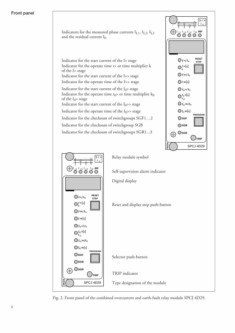
6
Fig. 2. Front panel of the combined overcurrent and earth-fault relay module SPCJ 4D29.
Relay module symbol
Self-supervision alarm indicator
Digital display
Reset and display step push-button
Selector push-button
TRIP indicator
Type designation of the module
Indicators for the measured phase currents IL1, IL2, IL3and the residual current I0
Indicator for the start current of the I> stageIndicator for the operate time t> or time multiplier kof the I> stageIndicator for the start current of the I>> stageIndicator for the operate time of the I>> stage
Indicator for the start current of the I0> stageIndicator for the operate time t0> or time multiplier k0of the I0> stageIndicator for the start current of the I0>> stage
Indicator for the operate time of the I0>> stage
Indicator for the checksum of switchgroups SGF1…2
Indicator for the checksum of switchgroup SGB
Indicator for the checksum of switchgroups SGR1...3
Front panel
[
SGR
SGB
SGF
SPCJ 4D29
TRIP
PROGRAM
RESETSTEP
L1 L2 L3 o IRF
3 >II
IIII
> nI I/
ks>t ]
n>>I I/
s>>[ ]t
so >ko
[ ]t
no >I I/
s>>ot [ ]
n>>o I/I
0012
A
[
SGR
SGB
SGF
SPCJ 4D29
TRIP
PROGRAM
RESETSTEP
L1 L2 L3 o IRF
3 >II
IIII
> nI I/
ks>t ]
n>>I I/
s>>[ ]t
so >ko
[ ]t
no >I I/
s>>ot [ ]
n>>o I/I
0012
A
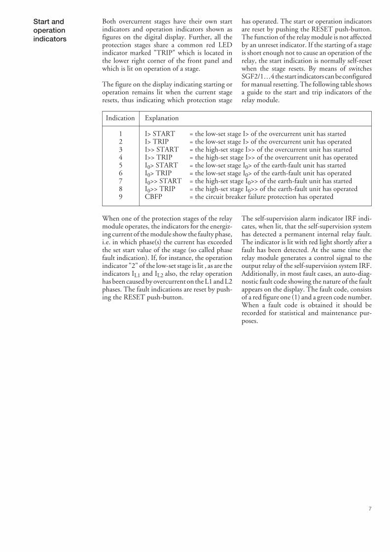
7
Both overcurrent stages have their own startindicators and operation indicators shown asfigures on the digital display. Further, all theprotection stages share a common red LEDindicator marked "TRIP" which is located inthe lower right corner of the front panel andwhich is lit on operation of a stage.
The figure on the display indicating starting oroperation remains lit when the current stageresets, thus indicating which protection stage
has operated. The start or operation indicatorsare reset by pushing the RESET push-button.The function of the relay module is not affectedby an unreset indicator. If the starting of a stageis short enough not to cause an operation of therelay, the start indication is normally self-resetwhen the stage resets. By means of switchesSGF2/1…4 the start indicators can be configuredfor manual resetting. The following table showsa guide to the start and trip indicators of therelay module.
Indication Explanation
1 I> START = the low-set stage I> of the overcurrent unit has started2 I> TRIP = the low-set stage I> of the overcurrent unit has operated3 I>> START = the high-set stage I>> of the overcurrent unit has started4 I>> TRIP = the high-set stage I>> of the overcurrent unit has operated5 I0> START = the low-set stage I0> of the earth-fault unit has started6 I0> TRIP = the low-set stage I0> of the earth-fault unit has operated7 I0>> START = the high-set stage I0>> of the earth-fault unit has started8 I0>> TRIP = the high-set stage I0>> of the earth-fault unit has operated9 CBFP = the circuit breaker failure protection has operated
When one of the protection stages of the relaymodule operates, the indicators for the energiz-ing current of the module show the faulty phase,i.e. in which phase(s) the current has exceededthe set start value of the stage (so called phasefault indication). If, for instance, the operationindicator "2" of the low-set stage is lit , as are theindicators IL1 and IL2 also, the relay operationhas been caused by overcurrent on the L1 and L2phases. The fault indications are reset by push-ing the RESET push-button.
The self-supervision alarm indicator IRF indi-cates, when lit, that the self-supervision systemhas detected a permanent internal relay fault.The indicator is lit with red light shortly after afault has been detected. At the same time therelay module generates a control signal to theoutput relay of the self-supervision system IRF.Additionally, in most fault cases, an auto-diag-nostic fault code showing the nature of the faultappears on the display. The fault code, consistsof a red figure one (1) and a green code number.When a fault code is obtained it should berecorded for statistical and maintenance pur-poses.
Start andoperationindicators

8
symbol of the setting quantity shows the quan-tity currently being displayed.
I>/In Start current of the I> stage as a multiple of the rated current of the used energizinginput. Setting range 0.5...5.0 x In at definite time characteristic and 0.5…2.5 x In atinverse time characteristic.
Note! At inverse time characteristic any setting above 2.5 x In will be regarded as beingequal to 2.5 x In.
t> Operate time of the I> stage expressed in seconds, at definite time characteristic(SGF1/1-2-3 = 0-0-0). Setting range 0.05...300 s.
k Time multiplier of the I> stage at inverse time characteristic. Setting range 0.05...1.00.
I>>/In Start current of the I>> stage as a multiple of the rated current of the used energizinginput. Setting range 0.5...40.0 x In. Additionally the setting "infinite" (displayed asn - - -) can be selected with switch SGF2/5, which means that the high-set stage I>>is out of operation.
t>> Operate time of the I>> stage expressed in seconds. Setting range 0.04...300 s.
I0>/In Start current of the I0> stage as a multiple of the rated current of the used energizinginput. Setting range 0.1...0.8 x In.
t0> Operate time of the I0> stage, expressed in seconds, at definite time characteristic(SGF1/6-7-8 = 0-0-0). Setting range 0.05...300 s.
k0 Time multiplier k0 of the I0> stage at inverse time characteristic. Setting range0.05...1.00.
I0>>/In Start current of the I0>> stage as a multiple of the rated current of the used energizinginput. Setting range 0.1...10.0 x In. Additionally the setting "infinite" (displayed asn - - -) can be selected with switch SGF2/6, which means that the earth-fault stageI0>> is out of operation.
t0>> Operate time of the I0>> stage expressed in seconds. Setting range 0.05...300 s.
Further, the checksums of switchgroups SGF1,SGB and SGR1 are shown on the display whenthe indicators adjacent to the switchgroup sym-bols on the front panel are lit. The checksumsfor switchgroups SGF2, SGR2 and SGR3 arefound in the submenus under the main menu of
the first switchgroup. For further information,see chapter "Menus and registers". An exampleof how the checksum can be calculated manu-ally is given in manual "General characteristicsof D type relay modules..
Settings The setting values are shown by the right-mostthree digits of the display. When lit, the LEDindicators on the front panel adjacent to the
9
Selector switches Additional functions required in various appli-cations are selected with switchgroups SGF,SGB and SGR indicated on the front panel. Thenumbering of the switches, 1...8, and the switchpositions 0 and 1 are shown when the switch-
groups are set. Under normal service conditionsonly the checksums are shown. SwitchgroupsSGF2, SGR2 and SGR3 are found in the sub-menus of the main menus of switchgroups SGFand SGR.
Function switch-group SGF1
On delivery from the factory all switches SGF1are set at zero, i.e. the checksum for SGF1 is 0.
Switch Function
SGF1/1 Switches SGF1/1...3 are used for selecting the characteristic of the low-set overcurrentSGF1/2 stage I>, i.e. definite time operation characteristic or inverse definite minimum timeSGF1/3 (IDMT) characteristic. At IDMT characteristic the switches are also used for selecting
the required current/time characteristic for the stage.
SGF1/1 SGF1/2 SGF1/3 Characteristic Time or curve set
0 0 0 Definite time 0.05...300 s1 0 0 IDMT Extremely inverse0 1 0 IDMT Very inverse1 1 0 IDMT Normal inverse0 0 1 IDMT Long-time inverse1 0 1 IDMT RI-characteristic0 1 1 IDMT RXIDG-characteristic1 1 1 --- (Long-time inverse)
SGF1/4 Circuit breaker failure protection (CBFP).
When SGF1/4 =1 the trip signal TS2 will start a timer which will generates a delayedoperate signal via TS1, if the fault has not been cleared before the operate time haselapsed.When switch SGF1/4 = 0 the circuit breaker failure protection is out of operation.
SGF1/5 Automatic doubling of the set start current of the high-set overcurrent stage I>> whenthe protected object is energized.
When SGF1/5 = 0, no doubling of the start current setting of stage I>> is obtained.When SGF1/5 = 1, the start current setting of stage I>> doubles automatically.The doubling feature makes it possible to give the high-set stage a setting value belowthe connection inrush current level.
SGF1/6 Switches SGF1/6...8 are used for selecting the operation characteristic of the low-setSGF1/7 earth-fault stage I0>, i.e. definite time characteristic or inverse definite minimum timeSGF1/8 (IDMT) characteristic. At inverse definite minimum time characteristic the switches
are also used for selecting the current/time characteristic of the stage.
SGF1/6 SGF1/7 SGF1/8 Characteristic Time or curve
0 0 0 Definite time 0.05…300 s1 0 0 IDMT Extremely inverse0 1 0 IDMT Very inverse1 1 0 IDMT Normal inverse0 0 1 IDMT Long-time inverse1 0 1 IDMT RI-characteristic0 1 1 IDMT RXIDG-characteristic1 1 1 IDMT Not in use (long-time inverse)
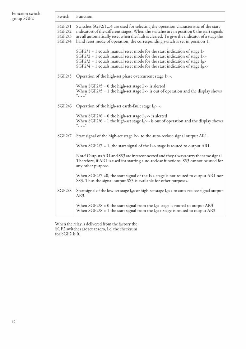
10
Function switch-group SGF2 Switch Function
SGF2/1 Switches SGF2/1...4 are used for selecting the operation characteristic of the startSGF2/2 indicators of the different stages. When the switches are in position 0 the start signalsSGF2/3 are all automatically reset when the fault is cleared. To give the indicator of a stage theSGF2/4 hand reset mode of operation, the corresponding switch is set in position 1:
SGF2/1 = 1 equals manual reset mode for the start indication of stage I>SGF2/2 = 1 equals manual reset mode for the start indication of stage I>>SGF2/3 = 1 equals manual reset mode for the start indication of stage I0>SGF2/4 = 1 equals manual reset mode for the start indication of stage I0>>
SGF2/5 Operation of the high-set phase overcurrent stage I>>.
When SGF2/5 = 0 the high-set stage I>> is alertedWhen SGF2/5 = 1 the high-set stage I>> is out of operation and the display shows"- - -"
SGF2/6 Operation of the high-set earth-fault stage I0>>.
When SGF2/6 = 0 the high-set stage I0>> is alertedWhen SGF2/6 = 1 the high-set stage I0>> is out of operation and the display shows"- - -"
SGF2/7 Start signal of the high-set stage I>> to the auto-reclose signal output AR1.
When SGF2/7 = 1, the start signal of the I>> stage is routed to output AR1.
Note! Outputs AR1 and SS3 are interconnected and they always carry the same signal.Therefore, if AR1 is used for starting auto-reclose functions, SS3 cannot be used forany other purpose.
When SGF2/7 =0, the start signal of the I>> stage is not routed to output AR1 norSS3. Thus the signal output SS3 is available for other purposes.
SGF2/8 Start signal of the low-set stage I0> or high-set stage I0>> to auto-reclose signal outputAR3.
When SGF2/8 = 0 the start signal from the I0> stage is routed to output AR3When SGF2/8 = 1 the start signal from the I0>> stage is routed to output AR3
When the relay is delivered from the factory theSGF2 switches are set at zero, i.e. the checksumfor SGF2 is 0.
11
Blocking or controlsignal configurationswitchgroup SGB
Switch Function
SGB/1 Switches SGB/1...4 are used for routing an external blocking signal BS to one or moreSGB/2 of the protection stages of the relay module. When the switches all are in position 0SGB/3 no stage is blocked.SGB/4
When SGB/1 = 1 the I> stage is blocked by the external control signal BSWhen SGB/2 = 1 the I>> stage is blocked by the external control signal BSWhen SGB/3 = 1 the I0> stage is blocked by the external control signal BSWhen SGB/4 = 1 the I0>> stage is blocked by the external control signal BS
SGB/5 Selection of main settings or second settings with an external control signal BS or viathe serial interface using command V150.
When SGB/5 = 0 the settings can be controlled via the serial port but not via theexternal control input BSWhen SGB/5 = 1, the settings can be controlled via the external control input. Themain values are enforced when the control input is not energized and the secondsettings are enforced when the control input is energized.
Note! When the application includes switching between main and second settings,it should be noted that switch SGB/5 must have the same position in the main set ofsettings and the second set of settings. Otherwise a conflict situation might occur whenthe settings are switched by external control or via the serial port.
SGB/6 Latching of the trip signal TS2 of the phase overcurrent unit.
When SGB/6 = 0 the trip signal returns to its initial state (= the output relay dropsoff), when the energizing signal causing the operation falls below the set start current.When SGB/6 = 1 the trip signal is latched (= the output relay remains picked up afteroperation), although the energizing signal falls below the start current. The trip signalis to be manually reset by pushing the push-buttons RESET and PROGRAMsimultaneously. 1)
SGB/7 Latching of the trip signal TS2 of the earth-fault unit.
When SGB/7 = 0 the trip signal returns to its initial state (= the output relay dropsoff), when the measuring signal causing the operation falls below the set start current.When SGB/7 = 1 the trip signal is latched (= the output relay remains picked up afteroperation), although the energizing signal falls below the start current. The trip signalis to be manually reset by pushing the push-buttons RESET and PROGRAMsimultaneously. 1)
SGB/8 Remote resetting of a latched output relay and memorized values.
When the output TS2 has been given the latching mode with switch SGB/6 or SGB/7,a remote reset can be performed using the external control input BS, when switchSGB/8 =1.
When the relay is delivered from the factory theSGB switches are set at zero, i.e. the checksumfor SGB is 0.
1) From the program versions 037F or 056Aand later versions an additional feature hasbeen incorporated into the relay module SPCJ4D29. When the latching function is usedthe latched output can be reset by pushing thePROGRAM button alone, in which case thestored information of the module is not erased.
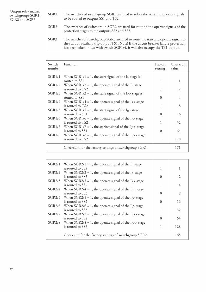
12
Output relay matrixswitchgroups SGR1,SGR2 and SGR3
SGR1 The switches of switchgroup SGR1 are used to select the start and operate signalsto be routed to outputs SS1 and TS2.
SGR2 The switches of switchgroup SGR2 are used for routing the operate signals of theprotection stages to the outputs SS2 and SS3.
SGR3 The switches of switchgroup SGR3 are used to route the start and operate signals tothe start or auxiliary trip output TS1. Note! If the circuit breaker failure protectionhas been taken in use with switch SGF1/4, it will also occupy the TS1 output.
Switch Function Factory Checksumnumber setting value
SGR1/1 When SGR1/1 = 1, the start signal of the I> stage isrouted to SS1 1 1
SGR1/2 When SGR1/2 = 1, the operate signal of the I> stageis routed to TS2 1 2
SGR1/3 When SGR1/3 = 1, the start signal of the I>> stage isrouted to SS1 0 4
SGR1/4 When SGR1/4 = 1, the operate signal of the I>> stageis routed to TS2 1 8
SGR1/5 When SGR1/5 = 1, the start signal of the I0> stageis routed to SS1 0 16
SGR1/6 When SGR1/6 = 1, the operate signal of the I0> stageis routed to TS2 1 32
SGR1/7 When SGR1/7 = 1, the staring signal of the I0>> stageis routed to SS1 0 64
SGR1/8 When SGR1/8 = 1, the operate signal of the I0>> stageis routed to TS2 1 128
Checksum for the factory settings of switchgroup SGR1 171
SGR2/1 When SGR2/1 = 1, the operate signal of the I> stageis routed to SS2 1 1
SGR2/2 When SGR2/2 = 1, the operate signal of the I> stageis routed to SS3 0 2
SGR2/3 When SGR2/3 = 1, the operate signal of the I>> stageis routed to SS2 1 4
SGR2/4 When SGR2/4 = 1, the operate signal of the I>> stageis routed to SS3 0 8
SGR2/5 When SGR2/5 = 1, the operate signal of the I0> stageis routed to SS2 0 16
SGR2/6 When SGR2/6 = 1, the operate signal of the I0> stageis routed to SS3 1 32
SGR2/7 When SGR2/7 = 1, the operate signal of the I0>> stageis routed to SS2 0 64
SGR2/8 When SGR2/8 = 1, the operate signal of the I0>> stageis routed to SS3 1 128
Checksum for the factory settings of switchgroup SGR2 165
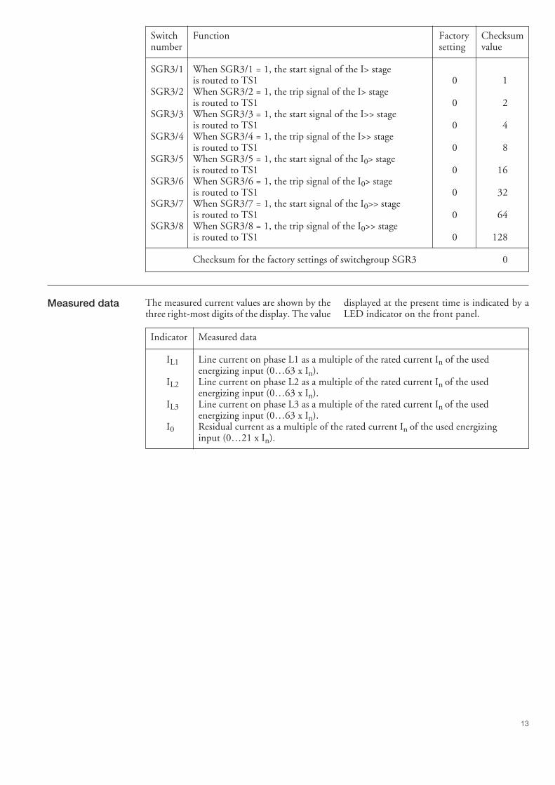
13
Switch Function Factory Checksumnumber setting value
SGR3/1 When SGR3/1 = 1, the start signal of the I> stageis routed to TS1 0 1
SGR3/2 When SGR3/2 = 1, the trip signal of the I> stageis routed to TS1 0 2
SGR3/3 When SGR3/3 = 1, the start signal of the I>> stageis routed to TS1 0 4
SGR3/4 When SGR3/4 = 1, the trip signal of the I>> stageis routed to TS1 0 8
SGR3/5 When SGR3/5 = 1, the start signal of the I0> stageis routed to TS1 0 16
SGR3/6 When SGR3/6 = 1, the trip signal of the I0> stageis routed to TS1 0 32
SGR3/7 When SGR3/7 = 1, the start signal of the I0>> stageis routed to TS1 0 64
SGR3/8 When SGR3/8 = 1, the trip signal of the I0>> stageis routed to TS1 0 128
Checksum for the factory settings of switchgroup SGR3 0
displayed at the present time is indicated by aLED indicator on the front panel.
Indicator Measured data
IL1 Line current on phase L1 as a multiple of the rated current In of the usedenergizing input (0…63 x In).
IL2 Line current on phase L2 as a multiple of the rated current In of the usedenergizing input (0…63 x In).
IL3 Line current on phase L3 as a multiple of the rated current In of the usedenergizing input (0…63 x In).
I0 Residual current as a multiple of the rated current In of the used energizinginput (0…21 x In).
Measured data The measured current values are shown by thethree right-most digits of the display. The value
14
The // symbol in the text indicates that the itemfollowing the symbol is found in a submenu.
Register/ Recorded informationSTEP
1 Phase current IL1 displayed as a multiple of the rated current of the used input of theovercurrent unit. If the overcurrent unit starts or operates, the current value at themoment of operation is recorded in a memory stack. Any new operation adds a newvalue to the stack and moves the old values one place forward. Five values arememorized. If a sixth value is recorded, the oldest value is lost.
2 Phase current IL2 measured as a multiple of the rated current of the used input of theovercurrent unit. If the overcurrent unit starts or operates, the current value at themoment of operation is recorded in a memory stack. Any new operation adds a newvalue to the stack and moves the old values one place forward. Five values arememorized. If a sixth value is recorded, the oldest value is lost.
3 Phase current IL3 measured as a multiple of the rated current of the used input of theovercurrent unit. If the overcurrent unit starts or operates, the current value at themoment of operation is recorded in a memory stack. Any new operation adds a newvalue to the stack and moves the old values one place forward. Five values arememorized. If a sixth value is recorded, the oldest value is lost.
4 Maximum demand current value for a period of 15 minutes expressed in multiplesof the rated current In of the used energizing input and based on the highest phasecurrent. // Highest maximum demand current value recorded after the last relayreset.
5 Duration of the last start situation of the I> stage as a percentage of the set operatetime t> or at IDMT characteristic the calculated operate time. At any new start thetime counter starts from zero. Five start times are memorized. If a sixth start occursthe oldest start time is lost. When the concerned stage has operated, the counterreading is 100. // Number of starts of the low-set overcurrent stage I>, n (I>) =0...255.
6 Duration of the last start situation of the I>> stage as a percentage of the set operatetime t>>. At any new start the time counter starts from zero. Five start times arememorized. If a sixth start occurs the oldest start time is lost. When the concernedstage has operated, the counter reading is 100. // Number of starts of the high-setovercurrent stage I>>, n (I>>) = 0...255.
7 Neutral current I0 displayed as a multiple of the rated current of the used energizinginput of the earth-fault unit. If the earth-fault unit starts or operates, the currentvalue at the moment of operation is recorded in a memory stack. Any new operationadds a new value to the memory stack and moves the old values forward one place.Five values are memorized - if a sixth value is recorded, the oldest value will be lost.
8 Duration of the latest start situation of stage I0> as a percentage of the set operate timet0> or in IDMT operation characteristic the calculated operate time. At any new startthe time counter starts from zero. Five start times are memorized. If a sixth start isrecorded the oldest start time is lost. When the concerned stage has operated, thecounter reading is 100. // Number of starts of the high-set overcurrent stage I>>, n(I>>) = 0...255.
9 Duration of the latest start situation of stage I0>> as a percentage of the set operatetime t0>>. At any new start the time counter starts from zero. Five start times arememorized. If a sixth start is recorded the oldest start time will be lost. When theconcerned stage has operated, the counter reading is 100. // Number of starts of thehigh-set earth-fault stage I0>>, n (I0>>) = 0...255.
Recordedinformation
The left-most red digit shows the address of theregister and the right-most three digits the re-corded value.
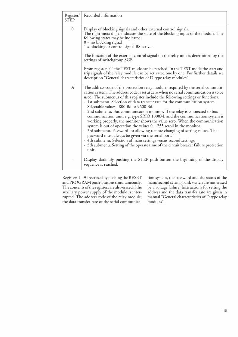
15
Register/ Recorded informationSTEP
0 Display of blocking signals and other external control signals.The right-most digit indicates the state of the blocking input of the module. Thefollowing states may be indicated:0 = no blocking signal1 = blocking or control signal BS active.
The function of the external control signal on the relay unit is determined by thesettings of switchgroup SGB
From register "0" the TEST mode can be reached. In the TEST mode the start andtrip signals of the relay module can be activated one by one. For further details seedescription "General characteristics of D type relay modules".
A The address code of the protection relay module, required by the serial communi-cation system. The address code is set at zero when no serial communication is to beused. The submenus of this register include the following settings or functions.- 1st submenu. Selection of data transfer rate for the communication system.
Selectable values 4800 Bd or 9600 Bd.- 2nd submenu. Bus communication monitor. If the relay is connected to bus
communication unit, e.g. type SRIO 1000M, and the communication system isworking properly, the monitor shows the value zero. When the communicationsystem is out of operation the values 0…255 scroll in the monitor.
- 3rd submenu. Password for allowing remote changing of setting values. Thepassword must always be given via the serial port.
- 4th submenu. Selection of main settings versus second settings.- 5th submenu. Setting of the operate time of the circuit breaker failure protection
unit.
- Display dark. By pushing the STEP push-button the beginning of the displaysequence is reached.
Registers 1...9 are erased by pushing the RESETand PROGRAM push-buttons simultaneously.The contents of the registers are also erased if theauxiliary power supply of the module is inter-rupted. The address code of the relay module,the data transfer rate of the serial communica-
tion system, the password and the status of themain/second setting bank switch are not erasedby a voltage failure. Instructions for setting theaddress and the data transfer rate are given inmanual "General characteristics of D type relaymodules".
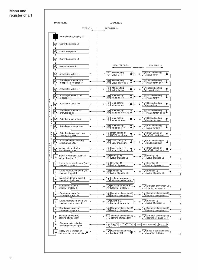
16
Normal status, display off
Current on phase L1
Current on phase L2
Current on phase L3
Neutral current Io
Maximum demand currentvalue for 15 minutes4
Second settingvalue for t> or k
Actual operate time t> or multiplier k for stage I>
21
Second settingvalue for I>> Actual start value I>> 21
Second settingvalue for t>>
Actual operate time t>> of stage I>>
21
Second setting value for Io>
Actual start value Io> 21
Second settingvalue for to> or ko
Actual operate time to>or multiplier ko
21
Second setting value for Io>> Actual start value Io>> 21
Second setting value for to>>
Actual operate time to>> 21
Main setting of SGF1 checksum
Actual setting of functionalswitchgroup SGF1
21
Actual setting of blockingswitchgroup SGB
1 Main setting of SGB checksum
Actual setting of relayswitchgroup SGR1
1 Main setting of SGR1 checksum
2
Event (n-1) value of phase L1
Event (n-2) value of phase L1
Latest memorized, event (n)value of phase L11 1 2
Event (n-1) value of phase L2
Event (n-2) value of phase L2
Latest memorized, event (n) value of phase L22 1 2
Event (n-1) value of phase L3
Event (n-2) value of phase L3
Latest memorized, event (n)value of phase L33 1 2
5 Duration of event (n-1) starting of stage I>
Duration of event (n-2) starting of stage I>
1 2
6 1 2Duration of event (n-1) starting of stage I>>
Duration of event (n-2) starting of stage I>>
Latest memorized, event (n) value of neutral current Io7 Event (n-1)
value of current IoEvent (n-2) value of current Io
1 2
8 1 2Duration of event (n-1)starting of stage Io>
Duration of event (n-2)starting of stage Io>
9 Duration of event (n-1)starting of stage Io>>
Duration of event (n-2)starting of stage Io>>
21
Status of external relay blocking / control signal0
Communication ratesetting [Bd]
Loss of bus traffic time counter 0..255 s
Relay unit identification address for communicationA 1 2
Main settingvalue for t> or k
Main settingvalue for I>>
Main settingvalue for t>>
Main setting value for Io>
Main settingvalue for to> or ko
Main setting value for Io>>
Main setting value for to>>
Second setting of SGB checksum
2
Second setting value for I>
21 Main setting value for I> Actual start value I>
0 000I> I>&t> I» I»&t» Io> Io>&to> Io» Io»&to»
Duration of event (n) starting of stage I>
Duration of event (n) starting of stage I>>
Duration of event (n)starting of stage Io>
Duration of event (n)starting of stage Io>>
SUBMENUSFWD. STEP 1 sREV. STEP 0.5 s
MA IN
MENU
REV.
STEP
.5s
FWD.
STEP
1s
1
2
3
5
6
7
8
9
A
MAIN MENU SUBMENUS
STEP 0.5 s PROGRAM 1 s
Highest maximum demand value found
1
Main setting of SGF2 checksum
Main setting of SGR2 checksum
Menu andregister chart
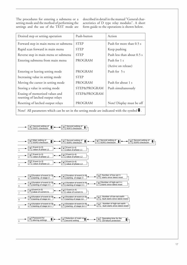
17
Second setting of SGF2 checksum
Second setting of SGR2 checksum
Event (n-3) value of phase L1
Event (n-4) value of phase L1
Event (n-3) value of phase L2
Event (n-4)value of phase L2
Event (n-3) value of phase L3
Event (n-4) value of phase L3
Duration of event (n-3) starting of stage I>
Duration of event (n-4) starting of stage I>
Duration of event (n-3) starting of stage I>>
Duration of event (n-4) starting of stage I>>
Event (n-3) value of current Io
Event (n-4) value of current Io
Duration of event (n-3)starting of stage Io>
Duration of event (n-4)starting of stage Io>
Duration of event (n-4)starting of stage Io>>
Password for altering settings
3 4
4
4
4
4
3
3
3
3
3
3
3
3
3
4
4
4
4
4
3
Number of low-set I>starts since latest reset
Number of high-set I>>starts since latest reset
Number of low-set earth-fault starts since latest reset
Number of high-set earth-fault starts since latest reset
Duration of event (n-3)starting of stage Io>>
5
5
5
5
Main setting of SGR3 checksum
Second setting of SGR3 checksum
5 6
1
2
3
5
6
7
8
9
A
Second setting of SGF1 checksum
Second setting of SGR1 checksum
Selection of main vs. second setting 4 Operating time for the
CB-failure protection5
The procedures for entering a submenu or asetting mode and the method of performing thesettings and the use of the TEST mode are
described in detail in the manual "General char-acteristics of D type relay modules". A shortform guide to the operations is shown below.
Desired step or setting operation Push-button Action
Forward step in main menu or submenu STEP Push for more than 0.5 s
Rapid scan forward in main menu STEP Keep pushing
Reverse step in main menu or submenu STEP Push less than about 0.5 s
Entering submenu from main menu PROGRAM Push for 1 s
(Active on release)
Entering or leaving setting mode PROGRAM Push for 5 s
Increasing value in setting mode STEP
Moving the cursor in setting mode PROGRAM Push for about 1 s
Storing a value in setting mode STEP&PROGRAM Push simultaneously
Erasing of memorized values and STEP&PROGRAMresetting of latched output relays
Resetting of latched output relays PROGRAM Note! Display must be off
Note! All parameters which can be set in the setting mode are indicated with the symbol .
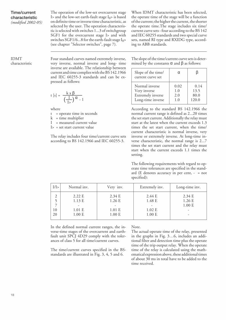
18
When IDMT characteristic has been selected,the operate time of the stage will be a functionof the current; the higher the current, the shorterthe operate time.The stage includes six time/current curve sets - four according to the BS 142and IEC 60255 standards and two special curvesets, named RI type and RXIDG type, accord-ing to ABB standards.
Four standard curves named extremely inverse,very inverse, normal inverse and long- timeinverse are available. The relationship betweencurrent and time complies with the BS 142.1966and IEC 60255-3 standards and can be ex-pressed as follows:
t [s] =
wheret = operate time in secondsk = time multiplierI = measured current valueI> = set start current value
The relay includes four time/current curve setsaccording to BS 142.1966 and IEC 60255-3.
The slope of the time/current curve sets is deter-mined by the constants α and β as follows:
Slope of the time/ α βcurrent curve set
Normal inverse 0.02 0.14Very inverse 1.0 13.5Extremely inverse 2.0 80.0Long-time inverse 1.0 120.0
According to the standard BS 142.1966 thenormal current range is defined as 2...20 timesthe set start current. Additionally the relay muststart at the latest when the current exceeds 1.3times the set start current, when the time/current characteristic is normal inverse, veryinverse or extremely inverse. At long-time in-verse characteristic, the normal range is 2...7times the set start current and the relay muststart when the current exceeds 1.1 times thesetting.
The following requirements with regard to op-erate time tolerances are specified in the stand-ard (E denotes accuracy in per cent, - = notspecified):
k x β I α I>
- 1( )
I/I> Normal inv. Very inv. Extremely inv. Long-time inv.
2 2.22 E 2.34 E 2.44 E 2.34 E5 1.13 E 1.26 E 1.48 E 1.26 E7 - - - 1.00 E
10 1.01 E 1.01 E 1.02 E -20 1.00 E 1.00 E 1.00 E -
In the defined normal current ranges, the in-verse-time stages of the overcurrent and earth-fault unit SPCJ 4D29 comply with the toler-ances of class 5 for all time/current curves.
The time/current curves specified in the BS-standards are illustrated in Fig. 3, 4, 5 and 6.
Note.The actual operate time of the relay, presentedin the graphs in Fig. 3…6, includes an addi-tional filter and detection time plus the operatetime of the trip output relay. When the operatetime of the relay is calculated using the math-ematical expression above, these additional timesof about 30 ms in total have to be added to thetime received.
Time/currentcharacteristic(modified 2002-05)
The operation of the low-set overcurrent stageI> and the low-set earth-fault stage I0> is basedon definite time or inverse time characteristic, asselected by the user. The operation characteris-tic is selected with switches 1...3 of switchgroupSGF1 for the overcurrent stage I> and withswitches SGF1/6...8 for the earth-fault stage I0>(see chapter "Selector switches", page 7).
IDMTcharacteristic
19
The RI-type characteristic is a special character-istic used mainly in combination with existingmechanical relays. The characteristic is based onthe following mathematical expression:
t [s] =
wheret = operate time in secondsk = time multiplierI = measured phase currentI> = set start current
The graph of the characteristic is shown inFig.7.
The RXIDG-type characteristic is a specialcharacteristic used mainly for earth-fault pro-tection, where a high degree of selectivity isneeded also for high-resistance faults. With thischaracteristic, the protection relay need not tobe directional and the scheme can operate with-out a pilot communication.
0.339 - 0.236 x
kI>I
RI-typecharacteristic
RXIDG-typecharacteristic
The characteristic is based on the followingmathematical expression:
t [s] = 5.8 - 1.35 x loge
wheret = operate time in secondsk = time multiplierI = measured phase currentI> = set start current
The graph of the characteristic is shown in Fig. 8.
Ik x I>( )
If the set start current exceeds 2.5 x In, themaximum permitted continuous current carry-ing capacity of the energizing inputs (4 x In)must be observed.
At inverse time characteristic the effective set-ting range of the low-set overcurrent stage is0.5…2.5 x In, although start current settingswithin the range 2.5…5.0 x In can be set on therelay. At inverse time characteristic any start
Note! current setting above 2.5 x In of the low-set stagewill be regarded as being equal to 2.5 x In.
The operation of the low-set stage based oninverse time characteristic will be blocked bystarting of the high-set stage. Then the operatetime of the overcurrent or earth-fault unit isdetermined by the set operate time of the high-set stage at heavy fault currents.
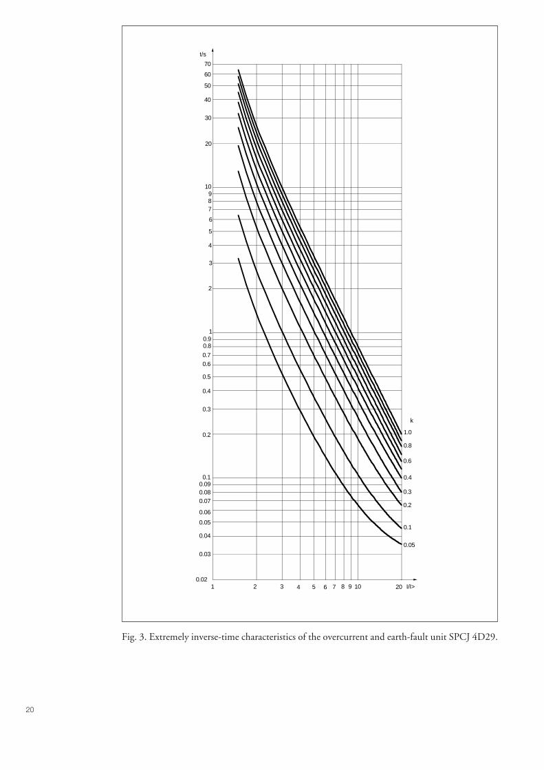
20
1 3 4 5 6 7 8 9 102 20 I/I>
0.05
0.1
0.2
0.3
0.4
0.6
0.8
1.0
k
0.02
0.03
0.04
0.05
0.06
0.070.080.090.1
0.2
0.3
0.4
0.5
0.6
0.7
0.80.9
1
2
3
4
5
6
789
10
20
30
40
70
60
50
t/s
Fig. 3. Extremely inverse-time characteristics of the overcurrent and earth-fault unit SPCJ 4D29.
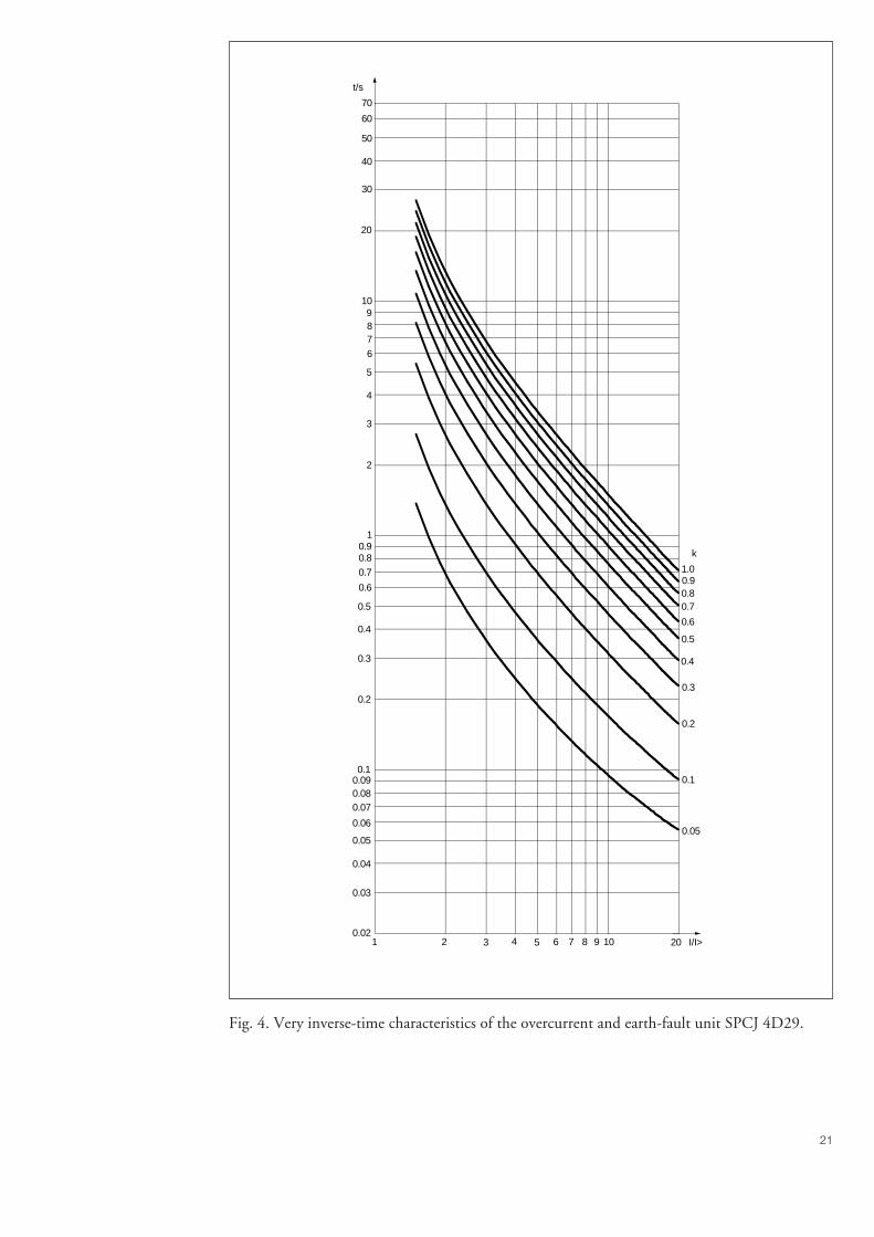
21
Fig. 4. Very inverse-time characteristics of the overcurrent and earth-fault unit SPCJ 4D29.
1 2 3 4 5 6 7 8 9 10 20 I/I>
0.05
0.1
0.2
0.3
0.4
0.5
0.6
0.70.80.91.0
k
0.02
0.03
0.04
0.05
0.06
0.070.080.090.1
0.2
0.3
0.4
0.5
0.6
0.7
0.80.9
1
2
3
4
5
6
789
10
20
70
60
50
40
30
t/s
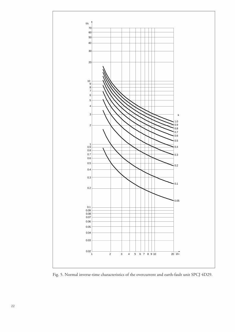
22
Fig. 5. Normal inverse-time characteristics of the overcurrent and earth-fault unit SPCJ 4D29.
0.05
0.1
0.2
0.3
0.4
0.5
0.60.70.80.91.0
k
1 2 3 4 5 7 8 9 10 20 I/I>60.02
0.03
0.04
0.05
0.06
0.070.080.090.1
0.2
0.3
0.4
0.5
0.6
0.7
0.80.9
1
2
3
4
5
6
789
10
20
30
40
50
60
70
t/s

23
Fig. 6. Long-time inverse-time characteristics of the overcurrent and earth-fault unit SPCJ 4D29.
1 2 3 4 5 10 206 7 8 9 I/I>
0.05
0.1
0.2
0.3
0.4
0.5
0.6
0.70.80.91.0
k
0.2
0.3
0.4
0.5
0.6
0.70.80.9
1
2
3
4
5
6
7
89
10
20
30
40
50
60
708090
100
200
300
400
500
600
700
t/s
24
Fig. 7. RI-type inverse-time characteristics of the overcurrent and earth-fault unit SPCJ 4D29.
1 2 3 4 5 6 7 8 9 10 20 I/I>
0.05
0.1
0.2
0.3
0.4
0.5
0.6
0.70.80.91.0
k
0.02
0.03
0.04
0.05
0.06
0.070.080.090.1
0.2
0.3
0.4
0.5
0.6
0.70.80.9
1
3
4
5
6
7
9
10
20
70
60
50
40
30
t/s
2
8
25
Fig. 8. RXIDG-type inverse-time characteristics of the overcurrent and earth-fault unit SPCJ 4D29.
0.6
0.7
0.8
0.9
1.0
k
1 2 3 5 7 8 9 10 20 I/I>60.02
0.03
0.04
0.05
0.06
0.070.080.090.1
0.2
0.3
0.4
0.5
0.6
0.7
0.80.9
1
2
3
4
5
78
10
20
30
40
50
60
70
t/s
30 40
6
9
0.05
4
0.1 0.2 0.4 0.50.3
26
Low-set overcurrent stage I>Start current- definite time characteristic 0.5...5.0 x In- inverse time characteristic 0.5…2.5 x InStart time, typ. 50 msOperation characteristic- definite time characteristic
- operate time 0.05...300 s- Inverse time characteristic acc. to
BS 142 and IEC 60255-3 Extremely inverseVery inverseNormal inverseLong-time inverse
- special characteristic acc. to ABB standards RI-type inverseRXIDG-type inverse
- time multiplier k 0.05...1.00Reset time, typ. 40 msRetardation time <30 msDrop-off/pick-up ratio, typ. 0.96Operate time accuracy at definite timeoperation characteristic ±2 % of set value or ±25 msOperate time accuracy class E at inversetime characteristic 5Operation accuracy ±3% of set value
High-set overcurrent stage I>>Start current I>> 0.5...40.0 x In or ∞, infiniteStart time, typ. 40 msOperate time 0.04...300 sReset time, typ. 40 msRetardation time <30 msDrop-off/pick-up ratio, typ. 0.98Operate time accuracy ±2% of set value or ±25 msOperation accuracy ±3% of set value
Low-set earth-fault stage I0>Start current I0> 0.1…0.8 x InStart time, typ. 60 msOperation characteristic- definite time characteristic
- operate time 0.05...300 s- Inverse time characteristic acc. to
BS 142 and IEC 60255-3 Extremely inverseVery inverseNormal inverseLong-time inverse
- special characteristic acc. to ABB standards RI-type inverseRXIDG-type inverse
- time multiplier k0 0.05...1.00Reset time, typ. 40 msRetardation time <30 msDrop-off/pick-up ratio, typ. 0.96Operate time accuracy at definite timeoperation characteristic ±2 % of set value or ±25 msOperate time accuracy class E at inversetime characteristic 5Operation accuracy ±3% of set value
Technical data
27
High-set earth-fault stage I0>>Start current I0>> 0.1...10.0 x In or ∞, infiniteStart time, typ. 40 msOperate time 0.05...300 sReset time, typ. 40 msDrop-off/pick-up ratio, typ. 0.98Operate time accuracy ±2% of set value or ±25 msOperation accuracy ±3% of set value
When the combined overcurrent and earth-fault relay module SPCJ 4D29 is connected toa data communication unit. e.g. SRIO 1000M,over a fibre-optic SPA bus, the module willspontaneously generate event markings e.g. fora printer. The events are printed out in theformat: time, text and event code. The text canbe defined and written by the user into thecommunication unit.
The events coded E1...E16 can be included inor excluded from the event reporting by writingan event mask V155 for the overcurrent eventsand V156 for earth-fault events to the moduleover the SPA bus. The event masks are binarynumbers coded to decimal numbers. The eventcodes E1...E8 are represented by the numbers 1,2, 4...128. An event mask is formed by multiply-ing the above numbers either by 0, event notincluded in reporting, or 1, event included inreporting and by adding the numbers received.Check for the procedure of a manual calculationof the checksum.
The event masks V155 and V156 may have avalue within the range 0...255. The defaultvalue of the combined overcurrent and earth-fault relay module SPCJ 4D29 is 85 both forovercurrent and earth-fault events, which meansthat all start and operate events are included inthe reporting, but not the resetting. Check for
the procedure of a manual calculation of thechecksum.
The output signals are monitored by codesE17...E26 and these events can be included in orexcluded from the event reporting by writing anevent mask V157 to the module. The eventmask is a binary number coded to a decimalnumber. The event codes E17...E26 are repre-sented by the numbers 1, 2, 4...512. An eventmask is formed by multiplying the above num-bers either by 0, event not included in reportingor 1, event included in reporting and by addingthe numbers received. Check for the procedureof a manual calculation of the checksum.
The event mask V157 may have a value withinthe range 0...1024. The default value of thecombined overcurrent and earth-fault relaymodule SPCJ 4D29 is 768 which means thatonly the operations are included in the report-ing.
Codes E50...E54 and the events represented bythese cannot be excluded from the reporting.
More information about the serial communica-tion over the SPA bus can be found in themanual "SPA bus communication protocol",code No 34 SPACOM 2 EN1.
Event codes of the combined overcurrent and earth-fault relay module SPCJ 4D29:
Code Event Weight factor Default valueof the factor
E1 Starting of stage I> 1 1E2 Resetting of starting of stage I> 2 0E3 Operation of stage I> 4 1E4 Resetting of operation of stage I> 8 0E5 Starting of stage I>> 16 1E6 Resetting of starting of stage I>> 32 0E7 Operation of stage I>> 64 1E8 Resetting of operation of stage I>> 128 0
Default checksum for mask V155 85
Serialcommunicationparameters
Event codes

28
Note!The event codes E52-E54 are generated by thedata communication unit (SACO 100M, SRIO500M, SRIO 1000M, etc.)
Code Event Weight factor Default valueof the factor
E9 Starting of stage I0> 1 1E10 Resetting of starting of stage I0> 2 0E11 Operation of stage I0> 4 1E12 Resetting of operation of stage I0> 8 0E13 Starting of I0>> stage 16 1E14 Resetting of starting of stage I0>> 32 0E15 Operation of stage I0>> 64 1E16 Resetting of operation of stage I0>> 128 0
Default checksum for mask V156 85
E17 Output signal TS1 activated 1 0E18 Output signal TS1 reset 2 0E19 Output signal SS1 activated 4 0E20 Output signal SS1 reset 8 0E21 Output signal SS2 activated 16 0E22 Output signal SS2 reset 32 0E23 Output signal SS3 activated 64 0E24 Output signal SS3 reset 128 0E25 Output signal TS2 activated 256 1E26 Output signal TS2 reset 512 1
Default checksum for mask V157 768
E50 Restarting * -E51 Overflow of event register * -E52 Temporary interruption in data communication * -E53 No response from the module over the data
communication * -E54 The module responds again over the data
communication * -
0 not included in the event reporting1 included in the event reporting* no code number- cannot be programmed
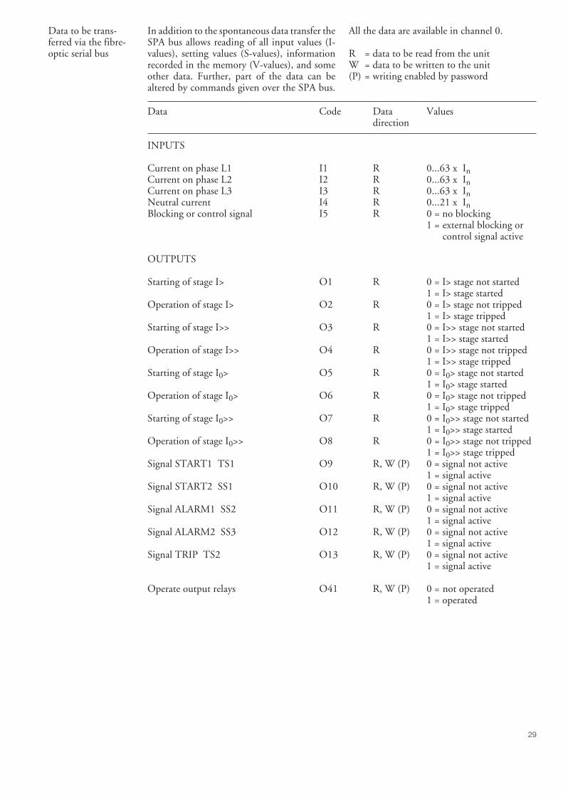
29
In addition to the spontaneous data transfer theSPA bus allows reading of all input values (I-values), setting values (S-values), informationrecorded in the memory (V-values), and someother data. Further, part of the data can bealtered by commands given over the SPA bus.
All the data are available in channel 0.
R = data to be read from the unitW = data to be written to the unit(P) = writing enabled by password
Data Code Data Valuesdirection
INPUTS
Current on phase L1 I1 R 0...63 x InCurrent on phase L2 I2 R 0...63 x InCurrent on phase L3 I3 R 0...63 x InNeutral current I4 R 0...21 x InBlocking or control signal I5 R 0 = no blocking
1 = external blocking orcontrol signal active
OUTPUTS
Starting of stage I> O1 R 0 = I> stage not started1 = I> stage started
Operation of stage I> O2 R 0 = I> stage not tripped1 = I> stage tripped
Starting of stage I>> O3 R 0 = I>> stage not started1 = I>> stage started
Operation of stage I>> O4 R 0 = I>> stage not tripped1 = I>> stage tripped
Starting of stage I0> O5 R 0 = I0> stage not started1 = I0> stage started
Operation of stage I0> O6 R 0 = I0> stage not tripped1 = I0> stage tripped
Starting of stage I0>> O7 R 0 = I0>> stage not started1 = I0>> stage started
Operation of stage I0>> O8 R 0 = I0>> stage not tripped1 = I0>> stage tripped
Signal START1 TS1 O9 R, W (P) 0 = signal not active1 = signal active
Signal START2 SS1 O10 R, W (P) 0 = signal not active1 = signal active
Signal ALARM1 SS2 O11 R, W (P) 0 = signal not active1 = signal active
Signal ALARM2 SS3 O12 R, W (P) 0 = signal not active1 = signal active
Signal TRIP TS2 O13 R, W (P) 0 = signal not active1 = signal active
Operate output relays O41 R, W (P) 0 = not operated1 = operated
Data to be trans-ferred via the fibre-optic serial bus
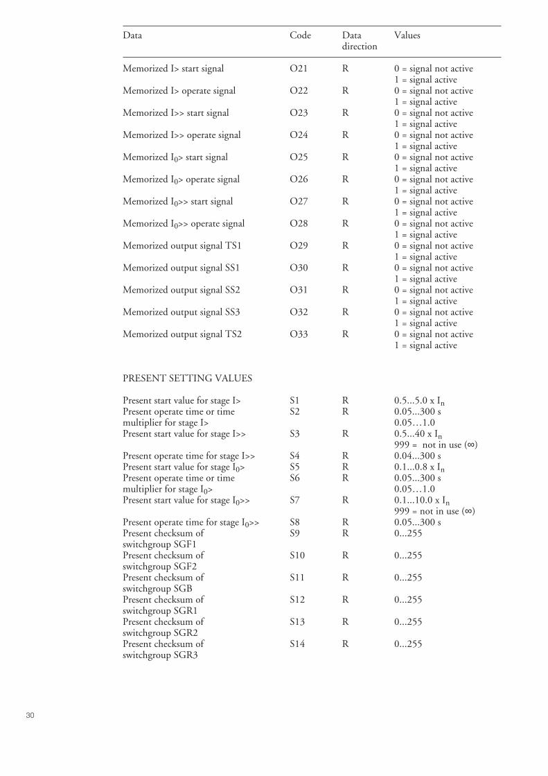
30
Data Code Data Valuesdirection
Memorized I> start signal O21 R 0 = signal not active1 = signal active
Memorized I> operate signal O22 R 0 = signal not active1 = signal active
Memorized I>> start signal O23 R 0 = signal not active1 = signal active
Memorized I>> operate signal O24 R 0 = signal not active1 = signal active
Memorized I0> start signal O25 R 0 = signal not active1 = signal active
Memorized I0> operate signal O26 R 0 = signal not active1 = signal active
Memorized I0>> start signal O27 R 0 = signal not active1 = signal active
Memorized I0>> operate signal O28 R 0 = signal not active1 = signal active
Memorized output signal TS1 O29 R 0 = signal not active1 = signal active
Memorized output signal SS1 O30 R 0 = signal not active1 = signal active
Memorized output signal SS2 O31 R 0 = signal not active1 = signal active
Memorized output signal SS3 O32 R 0 = signal not active1 = signal active
Memorized output signal TS2 O33 R 0 = signal not active1 = signal active
PRESENT SETTING VALUES
Present start value for stage I> S1 R 0.5...5.0 x InPresent operate time or time S2 R 0.05...300 smultiplier for stage I> 0.05…1.0Present start value for stage I>> S3 R 0.5...40 x In
999 = not in use (∞)Present operate time for stage I>> S4 R 0.04...300 sPresent start value for stage I0> S5 R 0.1...0.8 x InPresent operate time or time S6 R 0.05...300 smultiplier for stage I0> 0.05…1.0Present start value for stage I0>> S7 R 0.1...10.0 x In
999 = not in use (∞)Present operate time for stage I0>> S8 R 0.05...300 sPresent checksum of S9 R 0...255switchgroup SGF1Present checksum of S10 R 0...255switchgroup SGF2Present checksum of S11 R 0...255switchgroup SGBPresent checksum of S12 R 0...255switchgroup SGR1Present checksum of S13 R 0...255switchgroup SGR2Present checksum of S14 R 0...255switchgroup SGR3
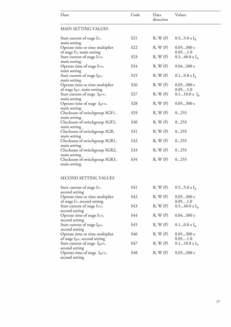
31
Data Code Data Valuesdirection
MAIN SETTING VALUES
Start current of stage I>, S21 R, W (P) 0.5...5.0 x Inmain settingOperate time or time multiplier S22 R, W (P) 0.05...300 sof stage I>, main setting 0.05…1.0Start current of stage I>>, S23 R, W (P) 0.5...40.0 x Inmain settingOperate time of stage I>>, S24 R, W (P) 0.04...300 smain settingStart current of stage I0>, S25 R, W (P) 0.1...0.8 x Inmain settingOperate time or time multiplier S26 R, W (P) 0.05...300 sof stage I0>, main setting 0.05…1.0Start current of stage I0>>, S27 R, W (P) 0.1...10.0 x Inmain settingOperate time of stage I0>>, S28 R, W (P) 0.05...300 smain settingChecksum of switchgroup SGF1, S29 R, W (P) 0...255main settingChecksum of switchgroup SGF2, S30 R, W (P) 0...255main settingChecksum of switchgroup SGB, S31 R, W (P) 0...255main settingChecksum of switchgroup SGR1, S32 R, W (P) 0...255main settingChecksum of switchgroup SGR2, S33 R, W (P) 0...255main settingChecksum of switchgroup SGR3, S34 R, W (P) 0...255main setting
SECOND SETTING VALUES
Start current of stage I>, S41 R, W (P) 0.5...5.0 x Insecond settingOperate time or time multiplier S42 R, W (P) 0.05...300 sof stage I>, second setting 0.05…1.0Start current of stage I>>, S43 R, W (P) 0.5...40.0 x Insecond settingOperate time of stage I>>, S44 R, W (P) 0.04...300 ssecond settingStart current of stage I0>, S45 R, W (P) 0.1...0.8 x Insecond settingOperate time or time multiplier S46 R, W (P) 0.05...300 sof stage I0>, second setting 0.05…1.0Start current of stage I0>>, S47 R, W (P) 0.1...10.0 x Insecond settingOperate time of stage I0>>, S48 R, W (P) 0.05...300 ssecond setting
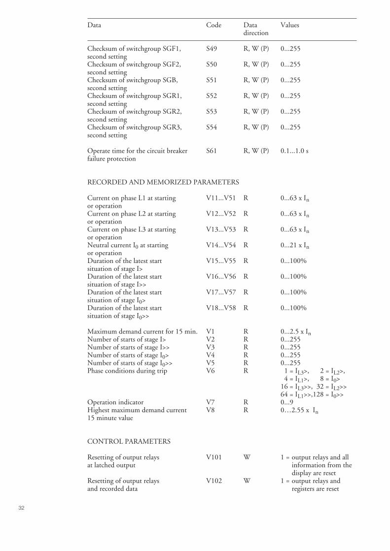
32
Data Code Data Valuesdirection
Checksum of switchgroup SGF1, S49 R, W (P) 0...255second settingChecksum of switchgroup SGF2, S50 R, W (P) 0...255second settingChecksum of switchgroup SGB, S51 R, W (P) 0...255second settingChecksum of switchgroup SGR1, S52 R, W (P) 0...255second settingChecksum of switchgroup SGR2, S53 R, W (P) 0...255second settingChecksum of switchgroup SGR3, S54 R, W (P) 0...255second setting
Operate time for the circuit breaker S61 R, W (P) 0.1...1.0 sfailure protection
RECORDED AND MEMORIZED PARAMETERS
Current on phase L1 at starting V11...V51 R 0...63 x Inor operationCurrent on phase L2 at starting V12...V52 R 0...63 x Inor operationCurrent on phase L3 at starting V13...V53 R 0...63 x Inor operationNeutral current I0 at starting V14...V54 R 0...21 x Inor operationDuration of the latest start V15...V55 R 0...100%situation of stage I>Duration of the latest start V16...V56 R 0...100%situation of stage I>>Duration of the latest start V17...V57 R 0...100%situation of stage I0>Duration of the latest start V18...V58 R 0...100%situation of stage I0>>
Maximum demand current for 15 min. V1 R 0...2.5 x InNumber of starts of stage I> V2 R 0...255Number of starts of stage I>> V3 R 0...255Number of starts of stage I0> V4 R 0...255Number of starts of stage I0>> V5 R 0...255Phase conditions during trip V6 R 1 = IL3>, 2 = IL2>,
4 = IL1>, 8 = I0>16 = IL3>>, 32 = IL2>>64 = IL1>>,128 = I0>>
Operation indicator V7 R 0...9Highest maximum demand current V8 R 0…2.55 x In15 minute value
CONTROL PARAMETERS
Resetting of output relays V101 W 1 = output relays and allat latched output information from the
display are resetResetting of output relays V102 W 1 = output relays andand recorded data registers are reset
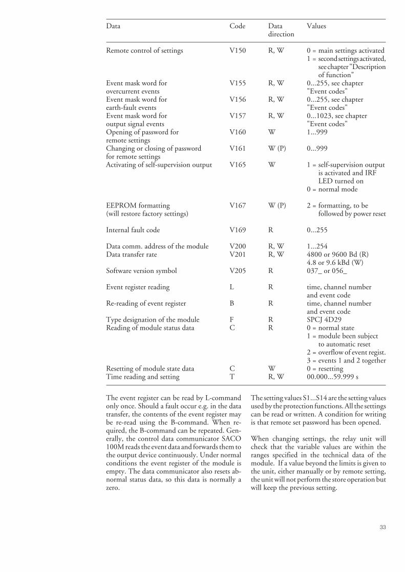
33
Data Code Data Valuesdirection
Remote control of settings V150 R, W 0 = main settings activated1 = second settings activated,
see chapter "Descriptionof function"
Event mask word for V155 R, W 0...255, see chapterovercurrent events "Event codes"Event mask word for V156 R, W 0...255, see chapterearth-fault events "Event codes"Event mask word for V157 R, W 0...1023, see chapteroutput signal events "Event codes"Opening of password for V160 W 1...999remote settingsChanging or closing of password V161 W (P) 0...999for remote settingsActivating of self-supervision output V165 W 1 = self-supervision output
is activated and IRFLED turned on
0 = normal mode
EEPROM formatting V167 W (P) 2 = formatting, to be(will restore factory settings) followed by power reset
Internal fault code V169 R 0...255
Data comm. address of the module V200 R, W 1...254Data transfer rate V201 R, W 4800 or 9600 Bd (R)
4.8 or 9.6 kBd (W)Software version symbol V205 R 037_ or 056_
Event register reading L R time, channel numberand event code
Re-reading of event register B R time, channel numberand event code
Type designation of the module F R SPCJ 4D29Reading of module status data C R 0 = normal state
1 = module been subjectto automatic reset
2 = overflow of event regist.3 = events 1 and 2 together
Resetting of module state data C W 0 = resettingTime reading and setting T R, W 00.000...59.999 s
The event register can be read by L-commandonly once. Should a fault occur e.g. in the datatransfer, the contents of the event register maybe re-read using the B-command. When re-quired, the B-command can be repeated. Gen-erally, the control data communicator SACO100M reads the event data and forwards them tothe output device continuously. Under normalconditions the event register of the module isempty. The data communicator also resets ab-normal status data, so this data is normally azero.
The setting values S1...S14 are the setting valuesused by the protection functions. All the settingscan be read or written. A condition for writingis that remote set password has been opened.
When changing settings, the relay unit willcheck that the variable values are within theranges specified in the technical data of themodule. If a value beyond the limits is given tothe unit, either manually or by remote setting,the unit will not perform the store operation butwill keep the previous setting.
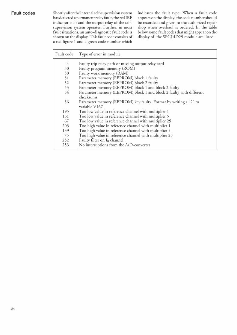
34
Fault codes Shortly after the internal self-supervision systemhas detected a permanent relay fault, the red IRFindicator is lit and the output relay of the self-supervision system operates. Further, in mostfault situations, an auto-diagnostic fault code isshown on the display. This fault code consists ofa red figure 1 and a green code number which
indicates the fault type. When a fault codeappears on the display, the code number shouldbe recorded and given to the authorized repairshop when overhaul is ordered. In the tablebelow some fault codes that might appear on thedisplay of the SPCJ 4D29 module are listed:
Fault code Type of error in module
4 Faulty trip relay path or missing output relay card30 Faulty program memory (ROM)50 Faulty work memory (RAM)51 Parameter memory (EEPROM) block 1 faulty52 Parameter memory (EEPROM) block 2 faulty53 Parameter memory (EEPROM) block 1 and block 2 faulty54 Parameter memory (EEPROM) block 1 and block 2 faulty with different
checksums56 Parameter memory (EEPROM) key faulty. Format by writing a "2" to
variable V167195 Too low value in reference channel with multiplier 1131 Too low value in reference channel with multiplier 567 Too low value in reference channel with multiplier 25
203 Too high value in reference channel with multiplier 1139 Too high value in reference channel with multiplier 575 Too high value in reference channel with multiplier 25
252 Faulty filter on I0 channel253 No interruptions from the A/D-converter


1MR
S 7
5011
7-M
UM
E
N
ABB OySubstation AutomationP.O.Box 699FIN-65101 VAASAFinlandTel. +358 (0)10 22 11Fax.+358 (0)10 22 41094www.abb.com/substationautomation