south african national standard - kwick · steel access scaffolding 1 scope 1.1 this part of sans...
TRANSCRIPT

ICS 91.220 ISBN 0-626-15672-6
SANS 10085-1:2004Edition 1.1
SOUTH AFRICAN NATIONAL STANDARD
The design, erection, use and inspection of access scaffolding
Part 1: Steel access scaffolding
Published by Standards South Africa 1 dr lategan road groenkloof private bag x191 pretoria 0001 tel: 012 428 7911 fax: 012 344 1568 international code + 27 12 www.stansa.co.za © Standards South Africa
This eStandard is exclusively for Proactive Risk Management for use on one standalone PC. To access it from a file server/Intranet constitutes a violation of SABS copyright rules. Note that only one printout of the standard may be made.

SANS 10085-1:2004 Edition 1.1 Table of changes Change No. Date Scope
Amdt 1 2004 Amended to delete a referenced standard and to correct cross-references.
Abstract Covers steel access scaffolding commonly used for supporting workers and materials, plant or equipment during construction, maintenance and demolition work. Keywords access equipment, birdcage scaffolds, classification systems, construction, construction equipment, design, erecting (construction operation), foundations, inspection, instructions for use, putlog scaffolds, safety measures, scaffolding components, scaffolds, steels, suspended scaffolds, temporary structures, tower scaffolds. Foreword This South African standard was approved by National Committee StanSA TC 5120.52, Access equipment, in accordance with procedures of Standards South Africa, in compliance with annex 3 of the WTO/TBT agreement. This edition cancels and replaces edition 1 (SANS 10085-1:2003). A vertical line in the margin shows where the text has been modified by amendment No. 1. Annex B forms an integral part of this standard. Annexes A and C are for information only. Introduction This part of SANS 10085 has been prepared to define procedures for the design and erection of access scaffolding, including appropriate training, user responsibilities and control of scaffolding operations. Apart from provisions for the more orthodox forms of scaffolding, provisions are included for prefabricated systems. Procedures are also given for the inspection, care and maintenance of scaffolding. However efficient the individual components of a scaffolding system may be, it is of little avail if the construction of the scaffolding is inefficient. Persons erecting scaffolding should therefore be able to ensure that, at the time of handing over to the user, the scaffolding is adequate for its intended purpose. Effective training of personnel who erect and use scaffolding is possibly the most essential factor in preventing accidents amongst both those who erect scaffolding and those who use it. Furthermore, a quality system should be applied by competent personnel to facilitate the safe erection and use of scaffolding (see the SANS 9000/ISO 9000 series of standards).
This eStandard is exclusively for Proactive Risk Management for use on one standalone PC. To access it from a file server/Intranet constitutes a violation of SABS copyright rules. Note that only one printout of the standard may be made.

SANS 10085-1:2004 Edition 1.1
1
Contents
Page Abstract Keywords Foreword Introduction 1 Scope ................................................................................................................................. 5 2 Normative references ......................................................................................................... 5 3 Definitions .......................................................................................................................... 7 4 Basic materials ................................................................................................................... 12 4.1 Timber ...................................................................................................................... 12 4.2 Steel ......................................................................................................................... 12 4.3 Aluminium ................................................................................................................ 12 4.4 Plastics .................................................................................................................... 12 5 Components ....................................................................................................................... 12 5.1 Couplers .................................................................................................................. 12 5.2 Joint pins (expanding spigot couplers) .................................................................... 13 5.3 Baseplates ............................................................................................................... 13 5.4 Soleboards ............................................................................................................... 14 5.5 Base jacks ............................................................................................................... 14 5.6 Cross-braces (for walk-through frames) .................................................................. 15 5.7 Flip locks (for walk-through frames) ......................................................................... 15 5.8 Hop-up brackets ...................................................................................................... 15 5.9 Scaffold boards ........................................................................................................ 16 5.10 Standards and tubes ................................................................................................ 16 5.11 Ladders .................................................................................................................... 17 5.12 Wheels and castors ................................................................................................. 18 5.13 Steel beams for outrigger scaffolding ...................................................................... 18 6 Chains, ropes and fasteners .............................................................................................. 18 6.1 General .................................................................................................................... 18 6.2 Chains ...................................................................................................................... 18 6.3 Cables and ropes ..................................................................................................... 18 6.4 Nails ......................................................................................................................... 19 6.5 Bolts and nuts .......................................................................................................... 19 6.6 Fishplates, set-screws and ferrules ......................................................................... 19 7 Height restrictions, classification, usage and safety factors ............................................... 19 7.1 Height restrictions .................................................................................................... 19 7.2 Classification ............................................................................................................ 20 7.3 Safety factors ........................................................................................................... 22
This eStandard is exclusively for Proactive Risk Management for use on one standalone PC. To access it from a file server/Intranet constitutes a violation of SABS copyright rules. Note that only one printout of the standard may be made.

SANS 10085-1:2004 Edition 1.1
2
Contents (continued)
Page 8 Foundations for scaffolding ................................................................................................ 22 8.1 General .................................................................................................................... 22 8.2 Particular considerations ......................................................................................... 22 8.3 Existing structures ................................................................................................... 23 8.4 Normal foundations .................................................................................................. 23 9 Design requirements for access scaffolding ...................................................................... 23 9.1 Safe working load .................................................................................................... 23 9.2 Scaffolding of heights greater than 60 m high ......................................................... 23 9.3 Scaffolding less than 60 m high ............................................................................... 24 10 Erection of scaffolding ........................................................................................................ 24 10.1 General .................................................................................................................... 24 10.2 Standards ................................................................................................................ 24 10.3 Ledgers .................................................................................................................... 25 10.4 Transoms and putlogs ............................................................................................. 25 10.5 Bracing and ties ....................................................................................................... 26 10.6 Boarding .................................................................................................................. 26 10.7 Ladders .................................................................................................................... 27 10.8 Staircases ................................................................................................................ 27 10.9 Outrigger (cantilever beam) scaffolding ................................................................... 28 10.10 Tubular steel independent tied (tube-and-fitting) scaffolding ................................... 28 10.11 Tubular steel frame scaffolding ................................................................................ 30 10.12 Tubular steel system scaffolding ............................................................................. 32 10.13 Putlog (single) scaffolding ........................................................................................ 32 10.14 Mobile tower scaffolding .......................................................................................... 33 10.15 Birdcage scaffolding ................................................................................................ 34 10.16 Trestle scaffolding .................................................................................................... 34 10.17 Roof scaffolding ....................................................................................................... 35 10.18 Scaffolding ramps .................................................................................................... 35 10.19 Working platforms .................................................................................................... 36 10.20 Pavement gantries ................................................................................................... 36 10.21 Aprons (fans) ........................................................................................................... 37 10.22 Cantilever off-loading platforms ............................................................................... 37 10.23 Hoist tower scaffolding ............................................................................................. 37 11 Safety precautions ............................................................................................................. 38 11.1 General .................................................................................................................... 38 11.2 Construction ............................................................................................................. 38 11.3 Materials and tools ................................................................................................... 38 11.4 Maintenance and housekeeping .............................................................................. 39 11.5 Personal safety ........................................................................................................ 39 11.6 Safety signs ............................................................................................................. 40 11.7 Outrigger scaffolding ................................................................................................ 40 11.8 Mobile tower scaffolds ............................................................................................. 40 11.9 Frame scaffolding .................................................................................................... 40 11.10 System scaffolding ................................................................................................... 41 12 Inspection ........................................................................................................................... 41
This eStandard is exclusively for Proactive Risk Management for use on one standalone PC. To access it from a file server/Intranet constitutes a violation of SABS copyright rules. Note that only one printout of the standard may be made.

SANS 10085-1:2004 Edition 1.1
3
Contents (concluded )
Page 13 Maintenance and storage ................................................................................................... 42 13.1 Maintenance ............................................................................................................ 42 13.2 Storage .................................................................................................................... 42 14 Control of scaffolding operations ....................................................................................... 42 14.1 Establishing scaffolding requirements ..................................................................... 42 14.2 Site visit ................................................................................................................... 43 14.3 Written confirmation ................................................................................................. 43 14.4 Supply and erection of scaffolding ........................................................................... 43 14.5 Inspection of the scaffolding .................................................................................... 44 14.6 Handover of the scaffold .......................................................................................... 44 15 Responsibilities of the scaffold user ................................................................................... 44 15.1 Ensuring scaffold safety ........................................................................................... 44 15.2 Prohibition on alterations to the scaffold by users ................................................... 44 15.3 Co-operation with other users .................................................................................. 44 15.4 Emergency procedures ............................................................................................ 45 15.5 Safe work procedure for a scaffold where ties have to be removed ........................ 45 16 Training requirements for scaffolding personnel ................................................................ 45 16.1 General .................................................................................................................... 45 16.2 Training and experience requirements .................................................................... 46 16.3 Accreditation ............................................................................................................ 48 Figures 1-15 ............................................................................................................................. 49-64 Annex A (informative) Example of scaffolding design calculations ...................................... 65 Annex B (normative) Basic checklist for scaffold inspections ............................................ 67 Annex C (informative) Typical format for scaffold inspection register .................................. 68 Bibliography ........................................................................................................................... 68
This eStandard is exclusively for Proactive Risk Management for use on one standalone PC. To access it from a file server/Intranet constitutes a violation of SABS copyright rules. Note that only one printout of the standard may be made.

SANS 10085-1:2004 Edition 1.1
4
This page is intentionally left blank
This eStandard is exclusively for Proactive Risk Management for use on one standalone PC. To access it from a file server/Intranet constitutes a violation of SABS copyright rules. Note that only one printout of the standard may be made.

SANS 10085-1:2004 Edition 1.1
5
The design, erection, use and inspection of access scaffolding Part 1: Steel access scaffolding 1 Scope 1.1 This part of SANS 10085 covers steel access scaffolding commonly used for supporting workers and materials, plant or equipment during construction, maintenance and demolition work. 1.2 This part of SANS 10085 does not cover scaffolding for falsework (i.e. where scaffolding materials are used primarily for temporary support of the works during construction). 1.3 This part of SANS 10085 does not cover industrial rope access work, which is covered by SANS 10333. 1.4 This part of SANS 10085 does not cover suspended scaffolding. 1.5 This part of SANS 10085 does not cover the use of scaffolding for construction of temporary seating stands and stages which are covered in SANS 1169. NOTE The diagrams in this part of SANS 10085 have been included solely to illustrate the text and are not intended to serve as working drawings. 2 Normative references The following standards contain provisions which, through reference in this text, constitute provisions of this standard. All standards are subject to revision and, since any reference to a standard is deemed to be a reference to the latest edition of that standard, parties to agreements based on this standard are encouraged to take steps to ensure the use of the most recent editions of the standards indicated below. Information on currently valid national and international standards can be obtained from Standards South Africa. BS 970-1, Specification for wrought steels for mechanical and allied engineering purposes – Part 1: General inspection and testing procedures and specific requirements for carbon, carbon manganese, alloy and stainless steels. SANS 251 (SABS 251), Long-link and extra-long-link steel chains for general purposes. SANS 550-2 (SABS 550-2), Wooden ladders – Part 2: Single and extension ladders. SANS 657-1, Steel tubes for non-pressure purposes – Part 1: Sections for scaffolding, general engineering and structural applications.
This eStandard is exclusively for Proactive Risk Management for use on one standalone PC. To access it from a file server/Intranet constitutes a violation of SABS copyright rules. Note that only one printout of the standard may be made.

SANS 10085-1:2004 Edition 1.1
6
SANS 809 (SABS 809), Industrial restraint belts. SANS 813 (SABS 813), Clamps for wire ropes. SANS 820 (SABS 820), Mild steel nails. SANS 911, Natural fibre ropes. SANS 943 (SABS 943), Man-made fibre ropes. SANS 1024 (SABS 1024), Welded steel fabric for reinforcement of concrete. SANS 1186-1, Symbolic safety signs – Part 1: Standard signs and general requirements. SANS 1288 (SABS 1288), Preservative-treated timber. SANS 1304 (SABS 1304), Light ladders. SANS 1396 (SABS 1396), Wooden scaffold boards. SANS 1431, Weldable structural steels. SANS 1700-7-3, Fasteners – Part 7: External drive hexagon bolts and screws – Section 3: Hexagon head bolts – Product grade C. SANS 1700-7-5, Fasteners – Part 7: External drive hexagon bolts and screws – Section 5: Hexagon head screws – Product grade C. SANS 1700-14-13, Fasteners – Part 14: Hexagon nuts – Section 13: Hexagon nuts, style 2, with metric fine pitch thread – Product grades A and B. SANS 1700-14-14, Fasteners – Part 14: Hexagon nuts – Section 14: Hexagon thin nuts (chamfered) with metric fine pitch thread – Product grades A and B. SANS 1783-2 (SABS 1783-2), Sawn softwood timber – Part 2: Stress-graded structural timber and timber for frame wall construction. SANS 2262/ISO 2262 (SABS ISO 2262), General purpose thimbles for use with steel wire ropes – Specification. SANS 10140-2 (SABS 0140-2), Identification colour marking – Part 2: Identification of hazards and equipment in work situations. SANS 10162-1 (SABS 0162-1), The structural use of steel – Part 1: Limit-states design of hot-rolled steelwork. SANS 10162-2 (SABS 0162-2), The structural use of steel – Part 2: Limit-states design of cold-formed steelwork. SANS 10162-3 (SABS 0162-3), The structural use of steel – Part 3: Allowable stress design. Amdt 1 SANS 10162-4 (SABS 0162-4), The structural use of steel – Part 4: The design of cold-formed stainless steel structural members. SANS 50361/EN 361, Personal protective equipment against falls from a height – Full body harnesses.
This eStandard is exclusively for Proactive Risk Management for use on one standalone PC. To access it from a file server/Intranet constitutes a violation of SABS copyright rules. Note that only one printout of the standard may be made.

SANS 10085-1:2004 Edition 1.1
7
3 Definitions For the purposes of this part of SANS 10085 the following definitions apply: 3.1 access scaffold scaffolding temporary structure that provides access, on or from which persons work, or that is used to support materials, small plant or equipment 3.2 apron fan projecting screen or net intended to protect persons from falling objects 3.3 band-and-plate coupler (see figure 1(a)) type of double coupler which may be used for securing two tubes in parallel or at right angles to each other 3.4 base jack baseplate, provided with a screw jack, that is used to provide individual adjustment of the height of a vertical member of scaffolding 3.5 baseplate (see figure 2) plate for distributing the load from a standard or inclined strut over the bearing surface 3.6 birdcage scaffolding scaffolding consisting of more than two rows of standards, both in width and length, and commonly having a platform to provide access to high parts of a structure, for example, to a ceiling 3.7 brace tube fixed diagonally with respect to vertical or horizontal tubes of a scaffold, to ensure stability and to prevent distortion of the scaffolding 3.8 brace coupler (see figure 1(c)) DH coupler coupler (not a double coupler) used for securing two tubes at right angles to each other NOTE This type of coupler is not suitable for the transmission of main loads. 3.9 bridle horizontal member, between two putlogs, which supports intermediate putlogs where they cannot be supported in the wall, for example, at window openings (see figure 7) 3.10 buttress scaffolding extension behind a scaffold, for example, behind an independent scaffold, usually built to make the scaffold self-supporting; such buttress scaffolding could be continuous or intermittent
This eStandard is exclusively for Proactive Risk Management for use on one standalone PC. To access it from a file server/Intranet constitutes a violation of SABS copyright rules. Note that only one printout of the standard may be made.

SANS 10085-1:2004 Edition 1.1
8
3.11 clear-grade term used in the timber industry meaning "without knots" 3.12 competent person person who is competent by virtue of his training and experience in the erection and dismantling of scaffolding 3.13 components all the individual pieces used with tubes to construct scaffolding 3.14 corrosion free having a loss of thickness of material at any point, due to corrosion, not exceeding 0,5 mm and a total loss of material not exceeding 16 % of the original mass 3.15 double coupler load-carrying coupler used for securing two tubes at right angles to each other 3.16 factor of safety against overturning coefficient by which the maximum overturning moment is multiplied in order to calculate the righting moment required to ensure safety against overturning 3.17 foot-tie lowest level of ledgers and transoms fixed at a distance not exceeding 300 mm above the bottom of the standards and that may be located parallel to sloping ground 3.18 frame connector tube with a flat washer welded externally around its centre part, and with holes for interconnecting pins or bolts and nuts, that is used to attach the next level of frame scaffolding 3.19 frame scaffolding form of independent tied scaffolding that is constructed from frames of one of three types (see figure 11) and may also be used to construct a single tower 3.20 guardrail substantial rail intended to prevent persons from falling off the scaffolding 3.21 hazardous weather wind of speed greater than 40 km/h, or electric storms, or rainfall in excess of 40 mm/h 3.22 hop-up brackets (see figure 3) cantilever bracket attached to a standard, or ledger of tube and fitting scaffold, at intermediate or platform height to support a platform
This eStandard is exclusively for Proactive Risk Management for use on one standalone PC. To access it from a file server/Intranet constitutes a violation of SABS copyright rules. Note that only one printout of the standard may be made.

SANS 10085-1:2004 Edition 1.1
9
3.23 imposed load any loads applied to the scaffolding, other than self-mass 3.24 independent tied scaffolding scaffolding consisting of two rows of standards, built to provide access to a structure, and which is laterally supported by the structure by means of stability ties 3.25 joint pin expanding spigot coupler load-carrying coupler comprising an internal fitting for joining two members end to end 3.26 ledger longitudinal horizontal member fixed to the standards, and that may be used to support putlogs or transoms 3.27 lift height the distance from one level of ledgers and transoms to the next 3.28 mobile scaffolding scaffold structures which serve as mobile access and working towers, and which a) are assembled using prefabricated components, b) are capable of being moved manually on firm, level ground, c) are capable of being used free-standing, d) have one or more working platforms, and e) normally have four legs and four castors 3.29 outrigger braced or unbraced cantilever beam 3.30 outrigger scaffolding (see figure 6) cantilever beam scaffolding working platform supported on or by outriggers 3.31 professional engineer person registered as a professional engineer in terms of the Engineering Profession of South Africa Act, 2000 (Act No. 46 of 2000) 3.32 putlog transverse horizontal member which spans from a ledger to a bearing in the wall and which is used for supporting the platform
This eStandard is exclusively for Proactive Risk Management for use on one standalone PC. To access it from a file server/Intranet constitutes a violation of SABS copyright rules. Note that only one printout of the standard may be made.
SANS 10085-1:2004 Edition 1.1
10
3.33 putlog coupler coupler used for securing putlogs or transoms to ledgers 3.34 putlog scaffolding (see figure 7) scaffolding that is supported by a single row of standards and by the structure with which it is being used 3.35 reinforced ledger ledger incorporating reinforcement, usually of a lattice type, used to increase the uniformly-distributed load which may be safely imposed on the ledger to not less than 16,7 kN 3.36 reveal tie (see figure 8) member that is jacked or wedged between two opposing faces of an opening in the structure (for example, a window opening), to provide a fixing of the scaffold to the structure 3.37 safety factor ratio of the ultimate load (at failure) to the maximum working load on a member or structure NOTE In the case of timber, the proof load is normally taken as the ultimate load. 3.38 safe working load SWL maximum load, in kilograms, that it is permissible to impose on the access equipment 3.39 Scaffolding Supervisor person proficient in the erection, maintenance and control of scaffolding operations and who has a certificate of training as an Inspector of Scaffolding (see 16.2.6); the Team Leaders report to the Scaffolding Supervisor 3.40 sheeted scaffold scaffold which is enclosed by thin metal sheets, or reinforced plastic sheets, for the protection of workers or the public 3.41 sleeve coupler (see figure 1(b)) external load-carrying coupler used for joining two members end to end 3.42 soleboard soleplate spreader made of timber or of other suitable material and used to distribute the load from a scaffold onto the ground 3.43 standard vertical member used in the construction of tubular scaffolding for transmitting a load to the baseplate or base jack
This eStandard is exclusively for Proactive Risk Management for use on one standalone PC. To access it from a file server/Intranet constitutes a violation of SABS copyright rules. Note that only one printout of the standard may be made.

SANS 10085-1:2004 Edition 1.1
11
3.44 structure entity on which work is being done and where scaffolding is necessary as a means of access for the carrying out of this work 3.45 suspended scaffolding scaffolding suspended by steel cables from overhead supports 3.46 swivel coupler load-carrying coupler used for securing two tubes at an angle other than a right angle (for example, as in bracing) 3.47 system scaffolding independent scaffolding constructed by using units of a special design 3.48 Team Leader person, appointed in writing, to lead a scaffold erecting team (see 16.2.5 for training requirements) 3.49 toeboard barrier along the sides and ends of a platform and intended to prevent tools, materials and workers from falling or slipping off the platform 3.50 transom transverse horizontal member which spans from outer to inner ledgers and which may also support a platform 3.51 trestle (see figure 9) self-supporting stand for supporting boards to make a working platform 3.52 tube and fitting (tubular) scaffolding (see figure 4(a)) scaffolding constructed of scaffold tube and scaffold fittings 3.53 user employer or contractor, or a person appointed by the employer or contractor, who has the right of control over the use of the scaffolding NOTE The term user does not include a lessor of the scaffolding or any person employed in connection with the installation of the scaffolding. 3.54 wind loads vertical and horizontal loads consequent on the exposure of the access equipment and personnel to the wind, in the various positions where the equipment may be placed or installed 3.55 working platform platform whose purpose is to support the combined imposed loads of workers, materials and plant. The number of working platforms permitted in simultaneous usage on scaffolding frameworks is limited (see 7.2.3)
This eStandard is exclusively for Proactive Risk Management for use on one standalone PC. To access it from a file server/Intranet constitutes a violation of SABS copyright rules. Note that only one printout of the standard may be made.

SANS 10085-1:2004 Edition 1.1
12
4 Basic materials 4.1 Timber Timber used in scaffolding, other than as specified in 5.9.1 for scaffold boards, shall at least comply with the requirements for grade S5 given in SANS 1783-2. 4.2 Steel Steel, other than steel for tubes, bolts, nuts, nails, ferrules and set-screws, shall comply with the relevant requirements of the following: a) for general purposes, BS 970-1; and b) for structural steel, grade 300WA of SANS 1431 or equivalent. 4.3 Aluminium Aluminium shall be of sufficient strength and suitable quality to support the intended loads (see 5.10.4). 4.4 Plastics Plastics material shall be of a grade recommended by the manufacturer of the material as being suitable for the specific purpose for which it is to be used. 5 Components 5.1 Couplers 5.1.1 General A coupler shall be of one of the types given in column 1 of table 1. Putlog couplers shall be so designed as to allow platform boards to lie flat. Three types of couplers are illustrated in figure 1. 5.1.2 Safe working loads A coupler shall have a safe working load at least equal to the relevant of the loads given in columns 2 to 6 of table 1. NOTE The safe working load is determined by dividing the ultimate load (determined by testing) by the relevant factor of safety (see 7.3.2).
This eStandard is exclusively for Proactive Risk Management for use on one standalone PC. To access it from a file server/Intranet constitutes a violation of SABS copyright rules. Note that only one printout of the standard may be made.

SANS 10085-1:2004 Edition 1.1
13
Table 1 — Safe working loads for couplers
1 2 3 4 5 6
Safe working load kNa Type
Slip-on tube Shear Compression Distortionb
Bending kN•m
Band and plate coupler Double coupler Swivel coupler
6,25 6,25 6,25
– –
– –
14,71 14,71 7,35
– –
Putlog coupler Putlog end Sleeve coupler
0,62 –
3,12
– 2,12
–
– – –
– – –
– –
0,86 Joint pin Brace coupler
– 1,25
21,00 –
50,0 –
– –
– –
a 1 kN is approximately 100 kg force.
b The distortion load relates to a test where the coupler is restrained from slipping by a second coupler fitted to the same tube and may be limited by the slipping of both fittings or by the commencement of visible distortion of the fitting before slip occurs.
5.1.3 Swivel couplers Swivel couplers shall be so designed that the hinge pin is not subjected to bending. 5.2 Joint pins (expanding spigot couplers) A joint pin shall be so designed as to be self-centring and to provide bearing for at least 80 % of the end surface area of the tubes that it joins. The joint pin shall engage at least 75 mm in each of the tubes joined. 5.3 Baseplates (see figure 2) 5.3.1 Steel baseplates A steel baseplate shall a) be of steel that complies with 4.2(a), b) be square, having sides of at least 150 mm, c) be of thickness at least 6 mm, d) have a spigot of length at least 50 mm and of diameter not less than 10 mm and not more than
20 mm, fixed centrally on one face, and e) have two holes of diameter approximately 6 mm placed symmetrically on one diagonal of the square
plate and at a centre-to-centre distance of at least 100 mm.
This eStandard is exclusively for Proactive Risk Management for use on one standalone PC. To access it from a file server/Intranet constitutes a violation of SABS copyright rules. Note that only one printout of the standard may be made.

SANS 10085-1:2004 Edition 1.1
14
5.3.2 Timber baseplates A timber baseplate shall a) be of timber that complies with 4.1, b) be of length at least 450 mm and of width at least 225 mm or of both length and width at least
300 mm, c) be of thickness at least 45 mm, and d) have fixed to it two support cleats of length of at least 200 mm, of width at least 100 mm and of
thickness at least 45 mm, and shaped to locate the standard. A single cleat may be used only where the plank standard can be nailed for positive location.
5.3.3 Aluminium baseplates An aluminium baseplate shall a) be of aluminium that complies with 4.3, and b) comply with 5.3.1(b) to (e) (inclusive). 5.3.4 Concrete baseplates A concrete baseplate shall a) be of concrete that has a compressive strength of at least 20 MPa at 28 d (after casting) and shall
have been cast at least 14 d before being used, b) comply with 5.3.2(b) and (c), and c) be reinforced with welded steel fabric that complies with the requirements of SANS 1024 for fabric
reference No. 226 or higher. 5.4 Soleboards A soleboard shall a) be of timber that complies with 4.1, b) be of width at least 225 mm and of suitable length (see 8.4), c) be of thickness at least 32 mm if the scaffold height does not exceed 15 m, and d) be of thickness at least 45 mm if the scaffold height exceeds 15 m. 5.5 Base jacks 5.5.1 Steel base jacks of nominal diameter 38 mm These jacks shall have a) a welded baseplate as specified in 5.3.1, but without the spigot described in 5.3.1(d), b) an unthreaded length of 150 mm or more at the opposite end of the shaft to the baseplate,
This eStandard is exclusively for Proactive Risk Management for use on one standalone PC. To access it from a file server/Intranet constitutes a violation of SABS copyright rules. Note that only one printout of the standard may be made.

SANS 10085-1:2004 Edition 1.1
15
c) a safe working load of at least 30 kN for axial loading at full extension, and d) if the jack is constructed from tube, a rolled thread. Some lateral loading is to be expected in addition to the axial load, and a safe working load of 1,3 kN for lateral loading at full extension shall be required. 5.5.2 Steel base jacks of nominal diameter 35 mm These jacks shall have a) a welded baseplate as specified in 5.5.1(a), b) an unthreaded length of 150 mm or more at the opposite end of the shaft to the baseplate, c) a safe working load of at least 20 kN for axial loading at full extension, and d) a safe working load of at least 0,69 kN for lateral loading at full extension. 5.5.3 Aluminium base jacks Aluminium jacks shall have a) a welded baseplate that complies with the requirements of 5.3.3, but without the spigot described in
5.3.1(d), b) an unthreaded length of 150 mm or more at the opposite end of the shaft to the baseplate, c) a safe working load of at least 10 kN for axial loading at full extension, and d) a safe working load of at least 0,6 kN for lateral loading at full extension. 5.5.4 Swivel baseplates Base jacks may also be fitted with swivel baseplates. In this case the supplier shall provide information regarding safe working loads. 5.6 Cross-braces (for walk-through frames) Cross-braces shall be of a steel that complies with 4.2(b) and shall be of angle section of size at least 30 mm × 30 mm and of thickness at least 3 mm, or of tubular steel of strength at least equal to that of the angle section type. 5.7 Flip locks (for walk-through frames) The pin of a flip lock (which engages in the hole of the cross-brace) shall have an outside diameter of at least 12 mm, and shall be of a steel that complies with the requirements for grade 220 M07 of BS 970-1. 5.8 Hop-up brackets A hop-up bracket shall be a) of steel or aluminium that complies with 4.2(a) or 4.3, respectively, b) so designed that, when the hop-up bracket is fitted to the scaffolding, the bracket so effectively locks
into position that it cannot twist in the vertical plane, and c) fitted with a platform of width in the range 450 mm to 695 mm.
This eStandard is exclusively for Proactive Risk Management for use on one standalone PC. To access it from a file server/Intranet constitutes a violation of SABS copyright rules. Note that only one printout of the standard may be made.
SANS 10085-1:2004 Edition 1.1
16
5.9 Scaffold boards 5.9.1 Timber scaffold board 5.9.1.1 A timber scaffold board shall comply with the requirements of SANS 1396. The thickness and width of the board shall conform to the preferred dimensions given in SANS 1396. 5.9.1.2 Either clear-grade softwood timber ("solid") or clear-grade hardwood timber ("hardwood solid") scaffold boards (see table 5) shall be used at any particular building site. Softwood and hardwood scaffold boards shall not be mixed on the same work site. 5.9.2 Metal and plastics scaffold boards Metal and plastics scaffold boards shall a) be capable of supporting the loads appropriate to the class of scaffolding on which they are used
(see 7.2), b) be checkered, indented, ribbed or otherwise treated to prevent slipping, c) when open grid or mesh is used, have perforations of size not exceeding 20 mm, and d) be as strong and rigid in bending as an equivalent timber board. 5.10 Standards and tubes 5.10.1 Steel tubes for tubular scaffolding Steel tubes shall a) comply with the relevant requirements of SANS 657-1 and be of the nominal outside diameter,
thickness and grade of steel given in columns 2 to 4 (inclusive) of table 2, relative to the component given in column 1,
b) be corrosion free (in the context as defined), c) be cut at right angles to the axis of the standard or tube, and d) be straight, undistorted and free from kinks. NOTE The straightness of a standard or tube may be checked visually. 5.10.2 Steel tubes for frame (or tower) scaffolding (see figure 11) Steel tubes used in the fabrication of frames shall comply with the relevant requirements of SANS 657-1 and shall be of the nominal outside diameter, wall thickness and grade of steel given in columns 2 to 4 (inclusive) of table 2, relative to the component given in column 1. All joints shall be fully welded with a weld of sufficient size that the welded connection is stronger than the smaller of the tubes being welded. 5.10.3 Surface protection of steel standards and tubes All standards and tubes for use in corrosive environments shall be suitably protected against corrosion.
This eStandard is exclusively for Proactive Risk Management for use on one standalone PC. To access it from a file server/Intranet constitutes a violation of SABS copyright rules. Note that only one printout of the standard may be made.

SANS 10085-1:2004 Edition 1.1
17
5.10.4 Aluminium standards and tubes Aluminium standards and tubes shall have a minimum 0,2 % proof stress value of 250 MPa, and a minimum ultimate tensile strength (UTS) value of 290 MPa, and shall be of nominal outside diameter 48,4 mm and of nominal wall thickness 4,47 mm.
Table 2 — Steel standards and tubes for scaffolding
1 2 3 4 Nominal minimum outside diameter
of tube
Nominal wall thickness of
tube Component
mm mm
Grade of steel for tube
Steel tubes for tubular scaffolding 48 3,2 See SANS 657-1Upright and transverse members for walk-through frames 48 2,5 See SANS 657-1System scaffolding members made of scaffold tubesa 48 3,2 See SANS 657-1
System scaffolding members made of tubes other than scaffold tubesa
48 2,5 See SANS 657-1
Upright members of interlocking frame 42 2,5 See SANS 657-1Transverse members of part walk-through frame 42 2,5 See SANS 657-1Ladder section members of part walk-through frame 42 2,0 See SANS 657-1Transverse members of interlocking frame 34 2,5 See SANS 657-1Strut members of interlocking frame 27 2,0 See SANS 657-1a In system (or unit) scaffolding, the standards are made of scaffold tube. However, tubes other than scaffold tubes are sometimes used for members not subject to main loads or bending.
5.11 Ladders 5.11.1 Wooden ladders Wooden ladders shall comply with the relevant requirements for single and extension ladders of SANS 550-2. 5.11.2 Aluminium and glass reinforced plastics (GRP) ladders Aluminium and GRP ladders shall comply with the relevant requirements of SANS 1304. 5.11.3 Steel ladders Steel ladders shall a) be made of steel that complies with 4.2, b) have stiles that provide a satisfactory grip for workmen wearing gloves, for example, 48 mm diameter
tube is not suitable for stiles, c) have a clear width between stiles of at least 310 mm, d) have rungs which provide a non-slip support for workmen climbing the ladder, e) have equal rung spacing not exceeding 333 mm centre to centre, and f) if used vertically, provide a continuous ladder and be designed specifically for use with the type of
equipment on which it is fitted.
This eStandard is exclusively for Proactive Risk Management for use on one standalone PC. To access it from a file server/Intranet constitutes a violation of SABS copyright rules. Note that only one printout of the standard may be made.

SANS 10085-1:2004 Edition 1.1
18
5.12 Wheels and castors 5.12.1 All wheels and castors shall be selected for type, size and safe working load appropriate to the expected design loads. 5.12.2 Castors used for a mobile tower shall be of the swivel type and shall be fitted with brakes. They shall be so fixed that they cannot fall off the tower leg when the wheel is not in contact with the ground. 5.13 Steel beams for outrigger scaffolding Steel beams used for outrigger scaffolding shall be of steel that complies with 4.2(b). (See also figure 6.) 6 Chains, ropes and fasteners 6.1 General 6.1.1 Parts of ropes or chains that have knots shall not be subjected to a load. 6.1.2 All cables, ropes and chains shall have a breaking strength commensurate with the expected loads and taking into account the appropriate safety factor. 6.1.3 Slings shall be joined together by means of shackles of the correct size. 6.1.4 In chemically aggressive or corrosive environments, special care is needed when selecting suitable materials of adequate cross-section and suitable protection. 6.2 Chains Chains shall comply with the appropriate requirements of SANS 251. 6.3 Cables and ropes Cables shall be made of steel and ropes shall be made entirely of fibre. 6.3.1 Steel cables Steel cables shall a) be adequately protected against corrosion, b) be of continuous length, and c) at the ends only, be bound and spliced or secured by means of suitable cable clamps (that comply
with the requirements of SANS 813) around suitable thimbles (that comply with the requirements of SANS 2262).
6.3.2 Fibre ropes 6.3.2.1 Natural fibre ropes shall comply with the requirements for grade 1 manila or sisal of SANS 911. 6.3.2.2 Man-made fibre ropes shall comply with the appropriate requirements of SANS 943. 6.3.2.3 A fibre rope that has been subjected to freezing or one that contains ice shall be thawed out at 15 °C to 25 °C for a suitable length of time. 6.3.2.4 The ends of a rope shall be properly bound (whipped) to prevent unraveling.
This eStandard is exclusively for Proactive Risk Management for use on one standalone PC. To access it from a file server/Intranet constitutes a violation of SABS copyright rules. Note that only one printout of the standard may be made.

SANS 10085-1:2004 Edition 1.1
19
6.3.3 Knots for fibre ropes When fibre rope is used, the following knots are preferred (see figure 10): a) Noose knot, for forming a loop that will draw taut around an object; b) Clove hitch, for securing a rope to a round object; and c) Marlinspike hitch, for securing a rope to equipment that is to be lifted or dragged. 6.4 Nails Nails shall be of suitable diameter and length, and shall comply with the relevant requirements of SANS 820. 6.5 Bolts and nuts Bolts shall be of suitable diameter and length appropriate to the intended use, and bolts and nuts shall comply with the relevant requirements of SANS 1700-7-3, SANS 1700-7-5, SANS 1700-14-13 or SANS 1700-14-14. 6.6 Fishplates, set-screws and ferrules Fishplates, set-screws and ferrules shall be of suitable size and suitable quality, and shall be capable of withstanding the applied loads taking into account the appropriate factor of safety. 7 Height restrictions, classification, usage and safety factors 7.1 Height restrictions 7.1.1 Ordinary scaffolding The height of ordinary scaffolding shall not exceed, in the case of a) putlog scaffolding, 20 m (see 10.13), b) interlocking frame scaffolding, 30 m (see 10.11.4.1 ), c) a free-standing tower (mobile or static), the value calculated by multiplying the minimum width of the
tower at the base by the appropriate factor given in table 3. The height is measured to the top platform level (see figures 5(a) and 5(b)),
d) walk-through frame scaffolding, 45 m (see 10.11.4.2), and e) tubular or system scaffolding, 60 m (see 10.10 and 10.12). Where there is any doubt as to the maximum permissible height of a scaffold, the complete scaffolding design shall be approved by a person competent in scaffolding design or by a professional engineer.
Table 3 — Multiplier for calculating maximum tower height
1 2 3
Multiplication factor Maximum wind speed m/s Mobile towers Static towers
Exceeding 10 Not exceeding 10
3,0 3,5
3,5 4,0
This eStandard is exclusively for Proactive Risk Management for use on one standalone PC. To access it from a file server/Intranet constitutes a violation of SABS copyright rules. Note that only one printout of the standard may be made.

SANS 10085-1:2004 Edition 1.1
20
7.1.2 Special scaffolding There are no restrictions on specially designed scaffolding except that the scaffold design shall be approved by a person competent in scaffolding design or by a professional engineer. Aluminium and system scaffolding (other than those covered in this part of SANS 10085) are also considered to be special scaffolding and the system shall have been approved by a professional engineer. 7.2 Classification Classification details are given in table 4 for tube and fitting scaffolding, and table 5 for tubular steel system scaffolding. Every scaffold shall be of one of the classes shown in column 1 of the appropriate table, according to the maximum load to be allowed on the platform as given in column 4 of the same table. 7.2.1 Usage Examples of the usage for which each class of scaffolding is suitable are given in column 2 of tables 4 and 5. 7.2.2 Standards spacing and platform width The maximum spacing of standards, and the range of widths of platforms allowed for each class of scaffolding are given in columns 5 and 6 of tables 4 and 5. 7.2.3 Number of working platforms The maximum number and class of working platforms allowed at the same time on a scaffold of each class are given in column 3 of tables 4 and 5. To allow for continuity of work, additional non-working platforms, whose purpose is to subsequently become working platforms in a leap-frogging action, shall be permitted, provided the total number of platforms shall not exceed twice the maximum number of working platforms on a scaffold. This requirement relates to scaffolds of maximum height as given in 7.1.1. For scaffolds of height less than that given, the reduction in self-mass of the scaffold allows for the use of additional platforms or working platforms of total loads not more than the self-mass reduction.
This eStandard is exclusively for Proactive Risk Management for use on one standalone PC. To access it from a file server/Intranet constitutes a violation of SABS copyright rules. Note that only one printout of the standard may be made.

SANS 10085-1:2004 Edition 1.1
21
Table 4 — Classification of tube and fitting scaffolding
1 2 3 4 5 6
Maximum platform safe working load
(see 7.2.4)
Maximum spacing of standards
Platform width (excluding inside
boards) mm Class Examples of
usage
Maximum number of working platform
levels kg/m2 m Min. Max.
Very light (VL) Inspection Painting Stone cleaning
4 x VL
80
3
675
1 150
Light (L) Repointing Replacing windows Plastering Insulation
3 x L
160
2,5
900
1 150
Medium (M) (General purpose)
New building Brickwork Blockwork
2 x M 1 x VL
240
2
1 125
1 150
Heavy (H) Masonry Heavy cladding
1 x H 1 x L
1 x VL
320
1,8
1 125
1 380
Table 5 — Classification of tubular steel system scaffolding (This table is based on 60 m high scaffold with 6 boarded lifts,
but including working platforms as indicated in column 3.)
1 2 3 4 5 6
Maximum platform safe working load
(see 7.2.4)
Maximum spacing of standards
Platform width (excluding inside
boards) mm
Class Examples of usage
Maximum number of working platform
levels kg/m2 m Min. Max.
Very light (VL) Inspection Painting Stone cleaning
6 × VL
80
2,5
675
1 150
Light (L) Repointing Replacing windows Plastering Insulation
4 x L
160
2,5
900
1 150
Medium (M) New building Brickwork Blockwork
2 x M 1 x VL
240
2,5
1 125
1 150
Heavy (H) Masonry Heavy cladding
Refer to person competent in scaffolding design for recommendations
NOTE If a scaffold is less than 60 m high, the following items may be varied: a) the number of working platforms (see 7.2.3); and b) the number of additional non-working platforms.
This eStandard is exclusively for Proactive Risk Management for use on one standalone PC. To access it from a file server/Intranet constitutes a violation of SABS copyright rules. Note that only one printout of the standard may be made.

SANS 10085-1:2004 Edition 1.1
22
7.2.4 Loading The imposed loads shown in column 4 of tables 4 and 5 are the total for men and materials. Any unusual loading of a scaffold, or unusual distribution of loads, shall be investigated and approved by a person competent in scaffolding design before work commences. (See also clause 9.) 7.3 Safety factors The allocation of a safety factor in 7.3.1 to 7.3.3 (inclusive) implies that the actual loads imposed on any component, assembly or scaffold, when multiplied by the safety factor, shall not exceed the ultimate loads the component or assembly is capable of carrying. Care shall be taken to determine whether the safe working load marked on a component (or specified by a manufacturer) is based on the required safety factor and, if not, to modify the safe working load appropriately, as indicated in 7.3.1 to 7.3.3. 7.3.1 Chains, cables and ropes 7.3.1.1 Chains shall have a safety factor of at least 5. 7.3.1.2 Cables and ropes shall have a safety factor of at least 10. 7.3.2 Components All components used in static scaffolding shall have a safety factor of at least 2. This applies also to steel outriggers which support static platforms, and to frames. 7.3.3 Complete, erected scaffolding Every complete, erected static scaffold shall have a designed safety factor of at least 2. 8 Foundations for scaffolding 8.1 General The surface on which scaffolding is to be erected shall be approved by a Scaffolding Supervisor. Where doubt exists regarding the bearing capacity of the surface, a detailed investigation shall be carried out and, if necessary, the approval of a professional engineer obtained. 8.2 Particular considerations In particular, the following possible problems should be considered: a) soft in-situ material; b) poorly compacted fill material; c) underground cavities; d) expansive clays; e) collapsing sand;
This eStandard is exclusively for Proactive Risk Management for use on one standalone PC. To access it from a file server/Intranet constitutes a violation of SABS copyright rules. Note that only one printout of the standard may be made.

SANS 10085-1:2004 Edition 1.1
23
f) sloping ground (more than 1:6); g) shallow pipe lines or cables; and h) any other problem that may be apparent. 8.3 Existing structures Where scaffolding is to be erected on an existing structure (including the structure which is being constructed), care shall be taken that a) the structure is capable of carrying the local loads imposed (for example, cantilevers, thin slabs in
waffle and trough slab construction, hidden penetrations in the slab, etc.), and b) the existing work is not damaged by the scaffolding (i.e. floor finishes and especially waterproofing,
etc., are protected). 8.4 Normal foundations Where good founding material exists, the following provisions shall apply: a) unless founded on adequate concrete foundations at least 75 mm thick, every scaffold shall be
erected on soleboards that are continuously supported (see 5.4 and figures 4 and 7); b) the material under the soleboards shall be well compacted; c) for very hard or rocky ground conditions not subject to erosion, the length of the soleboard shall be at
least 450 mm per standard; d) for good hard soils, the soleboard shall be continuous under at least two standards and shall project
at least 500 mm beyond the last standard or 200 mm in the case of scaffolds of height not exceeding 15 m;
e) for soft soils (see also 8.1), double soleboards, one on top of the other, should be used as in (d)
above to obtain better load distribution. 9 Design requirements for access scaffolding 9.1 Safe working load The safe working load for system standards and for ledgers at 2 m spacing (with a joint in the standard ) shall be 24 kN. A typical scaffolding design calculation, using values from 7.2.3 and table 5, is shown in annex A. Any alternative calculation method used shall ultimately show that the total loading on any standard does not exceed 24 kN. 9.2 Scaffolding of heights greater than 60 m high Scaffolding of heights greater than 60 m high shall be considered as special scaffolding, and a design prepared. Compensation for the extra height will usually be achieved by reducing the spacing between the standards within the range allowed for the classification of the scaffold. For example, in the sample calculation shown in annex A, if a 2 m spacing of standards were used, with the medium duty classifi-cation, a maximum height of 100 m would be permissible.
This eStandard is exclusively for Proactive Risk Management for use on one standalone PC. To access it from a file server/Intranet constitutes a violation of SABS copyright rules. Note that only one printout of the standard may be made.

SANS 10085-1:2004 Edition 1.1
24
9.3 Scaffolding less than 60 m high Scaffolding of heights lower than 60 m may have additional platforms but a calculation shall still be made to determine the maximum permissible height of the scaffold with its additional platforms. The need for this calculation can be illustrated by the sample calculation used in annex A, i.e. if the loading of the medium duty scaffold were to be increased by one additional working platform for light duty (160 kg/m2), the permissible scaffold height would be limited to 30 m. This illustrates the importance of carefully controlling the number of working platforms on a scaffold. 10 Erection of scaffolding 10.1 General 10.1.1 Scaffolding shall be erected, altered or dismantled under the supervision of a competent person who has been appointed in writing for this purpose. 10.1.2 It is essential that, during erection, alteration or dismantling, there is sufficient bracing in position (including temporary bracing if necessary) and ties to the structure to ensure the stability of the scaffold. 10.1.3 All scaffolding shall have a safe means of access to each working platform. 10.1.4 The maximum deviations for scaffolding shall be as follows: a) Plumbness of standards: within 1:133 but a maximum offset of 50 mm. b) Level of ledgers and transoms: 1:100 but a maximum offset of 50 mm. NOTE On sloping ground, the lowest ledger, called a foot tie, is fixed with swivel couplers and follows the slope
of the ground. c) Spacing of standards, both length and width: 1:20 (reduced width may affect board placing). d) Vertical spacing of ledgers (lift height): 1:20. e) Coupler spacing at nodes (tube intersections): 300 mm, centre to centre. f) Level of soleboards: within 1:50 both along and across. 10.2 Standards Standards shall be a) fixed at longitudinal spacings not exceeding the appropriate of the values given in column 5 of
tables 4 and 5, relative to the class of scaffolding given in column 1, and at transverse spacings to suit the required width of the platform,
b) braced, where necessary, to a solid footing (for example, putlog scaffolding), c) tied to the structure, including the case of mobile scaffolding that exceeds the height calculated in
accordance with 7.1.1, d) in the case of independent scaffolding, plumb, or in the case of putlog scaffolding, inclined at
approximately 1:100 towards the top of the structure, and e) free of joints above the top working platform.
This eStandard is exclusively for Proactive Risk Management for use on one standalone PC. To access it from a file server/Intranet constitutes a violation of SABS copyright rules. Note that only one printout of the standard may be made.

SANS 10085-1:2004 Edition 1.1
25
10.3 Ledgers 10.3.1 Ledgers shall be horizontal and secured at right angles to each standard, except the lowest ledgers that shall be fixed parallel to sloping ground. (See 10.1.4(b).) 10.3.2 The lowest level of ledgers or foot ties shall be fixed not more than 300 mm above the bottom of the standards. 10.3.3 Joints in the ledgers shall be staggered by at least one bay in the length and shall be located not more than 900 mm from a standard. 10.3.4 Joints in the ledgers in successive lift heights shall also be staggered. 10.3.5 Ledgers shall be fixed at vertical spacings not exceeding 2,1 m. Where access underneath is required, and the scaffolding has been specially designed, the maximum initial height may be increased to 2,7 m. 10.3.6 The top ledger shall be fixed at least 1 m below the top of a standard. 10.4 Transoms and putlogs 10.4.1 Transoms and putlogs for unboarded lifts (i.e. where no working platform will be placed) shall be fixed at the same spacings as for standards (see 10.2), and at a distance not exceeding 250 mm from the standards. 10.4.2 Transoms and putlogs for boarded lifts (i.e. where working platforms will be placed) shall be fixed at spacings not exceeding the appropriate of the values given in column 3 of table 6, relative to the type and nominal thickness of board given in columns 1 and 2. 10.4.3 Putlog, brace or double couplers shall be used to fix transoms, putlogs or ledgers, except that for lifts less than 45 m from the top of the scaffolding, the transoms and putlogs shall be fixed by means of double couplers only. 10.4.4 In the case of putlog scaffolding, the flat end of a putlog that is fixed into the brickwork of the structure shall be horizontal except that where the scaffolding is erected against an existing structure, the flat end shall be vertical. 10.4.5 Putlogs opposite an opening shall be supported by an underslung bridle tube that is fixed to adjacent putlogs by means of brace or double couplers. 10.4.6 Transoms may extend outwards to provide for the fixing of longitudinal braces and may extend inwards to butt against the structure, or may be so positioned that a platform board (i.e. an inside board) can be placed between the structure and the standards.
This eStandard is exclusively for Proactive Risk Management for use on one standalone PC. To access it from a file server/Intranet constitutes a violation of SABS copyright rules. Note that only one printout of the standard may be made.

SANS 10085-1:2004 Edition 1.1
26
Table 6 — Spacing of supports and overhang of timber scaffold boards used for working platforms
1 2 3 4 5
Nominal thickness
Maximum distance between supports
Overhang of board mm Type of timber scaffold board
mm m Min. Max.
Clear-grade softwood ("solid"a) 38 50 76
1,25 2,00 3,00
70 70 70
150 200 250
Clear-grade hardwood ("hardwood solid"b) 38 50
2,00 3,00
70 70
150 200
Metal-strengthened 38 50 76
1,25 2,00 3,00
70 70 70
150 200 250
Laminated 32 45 70
1,25 2,00 3,00
70 70 70
150 200 250
Batten 32 38
1,25 2,00
70 70
150 200
a See 5.9.1. b Hardwood solid timber boards are identified by an additional letter H.
10.5 Bracing and ties Sufficient bracing and ties to the structure shall be applied to ensure the stability of the scaffold in all directions (see 10.10.3). 10.6 Boarding 10.6.1 Timber boards All timber boards used in the construction of a platform or ramp built of scaffolding materials shall comply with 5.9.1 and shall a) be of equal thickness and, in the case of adjacent boards in a platform, of equal length, b) overhang bearers by the appropriate distance given in columns 4 and 5 of table 6, except that at a
platform end, the platform overhang shall not exceed 250 mm for any thickness of board, and c) where overlapped, be secured at both ends to prevent displacement, or be fitted with a full-depth fillet
piece across the full width of the platform. (See also 10.18.) NOTE Where possible, overlapping should be avoided, but as this is not economical on frame and circular scaffolding, the provision of a fillet piece will reduce the tripping hazard and the risk of board displacement.
This eStandard is exclusively for Proactive Risk Management for use on one standalone PC. To access it from a file server/Intranet constitutes a violation of SABS copyright rules. Note that only one printout of the standard may be made.

SANS 10085-1:2004 Edition 1.1
27
10.6.2 Material other than timber When a platform is made from materials other than timber (see 5.10.3), it shall be free from jagged edges, warps, twists and tripping hazards. In addition, a) rolled steel plates shall be closely laid and each plate shall be securely fastened to the framework, b) open mesh grids shall be welded or riveted at all joints, and c) expanded metal sheets shall be welded to a frame. 10.7 Ladders 10.7.1 A ladder used in conjunction with scaffolding shall a) be firmly supported at the base and be so secured in position (with fastenings of such strength that
the stiles will fail before the fastenings fail) that the ladder is prevented from slipping, sliding or overturning,
b) extend at least 900 mm above the higher landing or platform to which it provides access, c) not have its reach extended by the tying together of two or more ladders, d) in the case of a single ladder, be not longer than 9 m, and e) always be fitted inside the scaffold framework. 10.7.2 In the case of scaffolding with vertical ladder access, the requirement for a cage may be waived, provided that rest platforms are provided at intervals not exceeding 8 m. Such platforms shall be fitted with toeboards and guardrails, as required for working platforms. 10.7.3 Typical ladder access to scaffolding is illustrated in figures 5(a) and 5(b). 10.8 Staircases 10.8.1 A staircase used for construction purposes shall a) be firmly secured in position to the scaffold structure, b) have landings at the entrance and exit to each stage, and c) have guardrails, which follow the route of the staircase and landings, fitted to the scaffold. 10.8.2 Staircase suppliers shall provide information regarding maximum heights and loadings for staircases. 10.8.3 Where landings are constructed of scaffolding materials, such landings shall comply with 10.4, with a medium duty (M) classification (see table 4). 10.8.4 Materials shall not be stored on staircases or landings. 10.8.5 Typical staircase access to scaffolding is illustrated in figure 12.
This eStandard is exclusively for Proactive Risk Management for use on one standalone PC. To access it from a file server/Intranet constitutes a violation of SABS copyright rules. Note that only one printout of the standard may be made.

SANS 10085-1:2004 Edition 1.1
28
10.9 Outrigger (cantilever beam) scaffolding NOTE Figure 6 illustrates the use of outriggers for a single platform but an alternative use of such outriggers may be to support static scaffolding above or suspend it below the outriggers, or both. 10.9.1 Outriggers The outriggers shall be steel beams designed in accordance with the provisions of SANS 10162-1, SANS 10162-2 or SANS 10162-4 but, in order to provide the safety factor given in 7.3.2, the permissible stresses given in SANS 10162-1, SANS 10162-2 or SANS 10162-4 shall be modified by multiplication by a factor of 0,75. Amdt 1 NOTE It is common practice to limit the cantilever length to 1,8 m and to adopt an anchor span length of 3,6 m. 10.9.2 Scaffolding Scaffolding built above or suspended below outriggers shall be so positively located on the outriggers that displacement is prevented. The scaffolding shall comply with 7.3.3 and shall be erected in accordance with clause 10. 10.9.3 Structure The parts of the building or structure on which the outriggers are supported shall be checked by means of calculations, or by the exercising of competent engineering judgement, to ensure that the required safety factor is assured without risk of damage to the building or structure. 10.10 Tubular steel independent tied (tube-and-fitting) scaffolding (see figure 4(a)) 10.10.1 Standards Standards shall be fixed in pairs in accordance with 10.2. 10.10.2 Baseplates and soleboards Baseplates shall generally be set on soleboards (see 8.4). Soleboards shall be recessed when used in loose soils (for example, sand) and on slopes. 10.10.3 Ties (see figure 8) 10.10.3.1 Scaffolding shall be tied to the structure as described in 10.10.3.2 to 10.10.3.9 below. 10.10.3.2 The ties used shall be either a) of the fixed type which is positively fixed to the structure (for example, by box ties around columns or
to designed anchor positions), or b) of the reveal type which relies on friction to provide the means of restraint. The reveal tube shall be
properly tightened but without damaging the structure. 10.10.3.3 Any single tie that may have to be removed to facilitate working operations shall be replaced, under the supervision of a competent person, before an adjacent tie is moved. (Such a tie is referred to in table 7 as movable.)
This eStandard is exclusively for Proactive Risk Management for use on one standalone PC. To access it from a file server/Intranet constitutes a violation of SABS copyright rules. Note that only one printout of the standard may be made.

SANS 10085-1:2004 Edition 1.1
29
10.10.3.4 The number of ties used to tie scaffolding to the structure shall be such that the area (measured in elevation) of scaffolding supported by each tie does not exceed the appropriate value given in columns 2 to 6 (inclusive) of table 7. 10.10.3.5 The ties shall be evenly spaced vertically and horizontally and, if the pattern of tying is rectangular, the larger dimension shall not exceed twice the smaller dimension. 10.10.3.6 The ties shall resist movement both towards and away from the structure. 10.10.3.7 The ties shall be positioned where the structure is sufficiently strong to resist a tie safe working load of at least 2 kN. 10.10.3.8 The ties shall be horizontal or shall slope slightly downwards away from the structure. 10.10.3.9 For sheeted scaffolds exceeding 15 m in height, the frequency of ties shall be calculated by a person competent in scaffolding design.
Table 7 — Tying frequency of independent scaffolding
Dimensions in square metres 1 2 3 4 5 6
Maximum area of scaffolding per tie No sheeting Sheetedb
Type of tie Tubular and unit system scaffolding
FrameTubular and unit system scaffolding
FramePutlog
(no sheeting)
Non-movable fixed tie 40a 32 32 24 32 Movable fixed tie 32 24 26 16 26 Non-movable reveal tie 22 16 18 12 18 Movable reveal tie 18 12 15 12 15 a For system (unit) scaffolding, see 10.12.2.4. b Columns 4 and 5 are applicable for scaffolds not exceeding 15 metres from ground level.
10.10.4 Bracing 10.10.4.1 Bracing shall be provided to prevent distortion of scaffolding. 10.10.4.2 Bracing shall be arranged in triangular-shaped patterns with connections at a distance not exceeding 300 mm from the intersections of vertical and horizontal members. 10.10.4.3 Longitudinal bracing on the outside of putlog and independent scaffolding shall be fixed at spacings not exceeding 10 bays horizontally and to the full height of the scaffolding. The bracing shall consist of joined tubes lapped together by means of two couplers or of a joint pin with a short tube lapped and fixed each side of the joint pin by means of a coupler or, on a scaffold not exceeding 15 m in height, by means of a sleeve coupler. 10.10.4.4 Bracing for ledgers shall be fixed to the full height of the scaffolding, and ledger to ledger. The bracing shall be fixed by means of brace couplers or double couplers near alternate pairs of standards. To accommodate boarded lifts and to avoid clashing with a toeboard, the bracing shall be from under the outside ledger of a platform down to the top of the inside ledger. 10.10.4.5 Plan bracing (see figures 5(a) and 5(b) for typical examples) between the inner and outer rows of standards shall be placed across the diagonal of a bay and shall be provided at spacings not exceeding 10 bays horizontally and, where possible, at the tie levels.
This eStandard is exclusively for Proactive Risk Management for use on one standalone PC. To access it from a file server/Intranet constitutes a violation of SABS copyright rules. Note that only one printout of the standard may be made.

SANS 10085-1:2004 Edition 1.1
30
10.10.5 Use of couplers 10.10.5.1 A ledger shall be connected to a standard by means of a double coupler. 10.10.5.2 Double couplers shall be used for all ties except that brace couplers may be used in the case of low-height and low-risk scaffolding, i.e. scaffolds of height not exceeding 15 m. 10.11 Tubular steel frame scaffolding 10.11.1 Information sheets The supplier of frame scaffolding shall provide the user with an information sheet which describes the correct method of use of the scaffolding and gives the height and load and other limitations of the scaf-folding. Sketches shall be included to illustrate the use of the scaffolding. 10.11.2 Type (see figure 11) Frame scaffolding shall be of one of the following types: a) interlocking frame; b) walk-through frame; or c) part walk-through frame. Frames of more than one type shall not be used in one scaffold. 10.11.3 Dimensions of frames The dimensions of frames shall be the appropriate of those given in table 8, subject to normal manu-facturing tolerances.
Table 8 — Dimensions of frames
1 2 3 4
Dimensions mm Type of frame
Width Height Distance between centres of flip locks
Interlocking 914 1 524 2 134 3 048
908 908 908 908
– – – –
Walk-through 1 219 1 981 1 219 or 1 372 Part walk-through 1 524
1 524 1 524
1 981 2 134 2 286
1 219 or 1 372 1 219 or 1 372 1 219 or 1 372
10.11.4 Construction 10.11.4.1 Interlocking frames 10.11.4.1.1 Interlocking frames shall only be used to construct towers (see figures 5(b) and 11).
This eStandard is exclusively for Proactive Risk Management for use on one standalone PC. To access it from a file server/Intranet constitutes a violation of SABS copyright rules. Note that only one printout of the standard may be made.

SANS 10085-1:2004 Edition 1.1
31
10.11.4.1.2 Towers shall be vertical. Knee braces or diagonal braces shall be used to stabilize the bottom pair of frames. 10.11.4.1.3 Plan braces shall be used at the top of the first pair of frames and then at every third pair of frames, to ensure that the towers are square. 10.11.4.1.4 In the case of a tower of height in excess of the relevant maximum given in 7.1.1, the tower shall be tied to the support structure. Both sides of the tower shall be tied and the vertical spacing of the ties shall not exceed three times the width of the base of the tower. 10.11.4.1.5 A mobile tower shall be fitted with locking castors and the ladder access shall be inside the tower to prevent overturning. 10.11.4.2 Walk-through and part walk-through frames 10.11.4.2.1 Scaffolding made of walk-through or part walk-through frames shall not be used for heavy cladding and masonry work, and the spacing of the standards and the platform arrangement shall comply with the relevant provisions of 7.1.1. 10.11.4.2.2 The outside face of the scaffolding shall be fully cross-braced. NOTE Some inside cross-braces may be replaced with horizontal tube and couplers that link the inside uprights of each lift of frames, as indicated in 10.11.4.2.3 to 10.11.4.2.5 (inclusive). 10.11.4.2.3 Every section of scaffolding of length not exceeding 24 m shall have at least two adjacent bays with cross-braces from top to bottom on the inside face. The outside face of the scaffolding shall be fully cross-braced. 10.11.4.2.4 Not more than four frames in height shall be without cross-braces. 10.11.4.2.5 Any area of the inside face of the scaffolding without cross-braces shall be of length not exceeding 20 m and of height not exceeding 8 m. 10.11.4.2.6 Plan braces shall be fixed at every third frame in height and at spacings of not more than 16 m along the scaffolding. In the case of part walk-through frame scaffolding and where frame scaffolding is used as a mobile tower, plan bracing using tube and fittings shall be provided. 10.11.4.2.7 Frames shall be located by means of frame connectors, and bolts or locking pins shall be used to fix the connector to at least one of the frames. The top three frames shall be fully connected except that, where the scaffolding is of height exceeding 30 m, a minimum of the top five frames shall be fully connected. Where scaffolding extends beyond the top of the structure, all frames above and at least three frames below the last tie level shall be fully connected. All free-standing scaffolding (with or without anchors or guys) shall have all joints fully connected. 10.11.4.2.8 Where scaffolding is tied to the structure, the type of tie and the tying procedure shall comply with 10.10.3. 10.11.4.3 Platforms for frame scaffolding Platforms shall comply with the requirements of 10.19.
This eStandard is exclusively for Proactive Risk Management for use on one standalone PC. To access it from a file server/Intranet constitutes a violation of SABS copyright rules. Note that only one printout of the standard may be made.

SANS 10085-1:2004 Edition 1.1
32
10.12 Tubular steel system scaffolding (see figure 4(b)) NOTE Differences in design and manufacture make it impracticable to deal in this part of SANS 10085 with every variation of scaffolding. 10.12.1 Information sheets The supplier of system scaffolding shall provide the user with an information sheet which describes the correct method of use of the scaffolding and gives the height and load and other limitations of the scaffolding. Sketches shall be included to illustrate the use of the scaffolding. 10.12.2 Construction 10.12.2.1 Upright members, whether inside or outside, may have staggered joints to provide better continuity for tying-in. 10.12.2.2 Staggered joints are preferred but common level joints are often appropriate, especially where the lengths of uprights are matched to storey heights on the structure. It is more important that ties be fixed near the top of upright members when joints are at a common level. 10.12.2.3 Longitudinal bracing shall be fixed to the upright members at spacings not exceeding eight bays or 20 m, whichever is less, and shall be provided over the full height of the scaffolding. 10.12.2.4 Scaffolding shall be tied to the structure. The type of tie and the tying procedure shall comply with 10.10.3 except that the area of scaffolding surface per tie shall not exceed 32 m2 and, if possible, ties shall be placed near the top of upright members and tie connection to horizontal members shall be avoided. 10.12.2.5 Transverse bracing, when used, shall be fixed to upright members of the scaffolding. Such bracing shall be used between tie levels when more than one upright member joint occurs between tie levels, and to alternate pairs of standards along the scaffold. 10.12.2.6 Plan bracing shall be fixed to upright members of the scaffolding, preferably at the tie levels, and at spacings not exceeding eight bays or 20 m, whichever is less. 10.12.2.7 The external upright members of all free-standing scaffolds shall have all joints fully connected by bolts or locking pins. For scaffolds not exceeding 30 m in height the top 8 m of all uprights shall be fully connected, and for scaffolds exceeding 30 m in height the top 13 m of all uprights shall be fully connected. 10.12.3 Classifications System scaffolds shall be classified in accordance with 7.2. The spacing of the standards and the number of working platforms shall be as given in table 5. 10.12.4 Platforms Platforms shall generally comply with the requirements of 10.19, but where steel boards that are only supported at each end are used, and as required for towers and birdcage scaffolds (see 10.14.2 and 10.15.3), reinforced ledgers shall be provided to safely support platforms for heavy work. 10.13 Putlog (single) scaffolding (see figure 7) Putlog scaffolding shall a) be so erected that the standards are not more than 1,5 m away from the walls of the structure, and
are inclined as described in 10.2(d),
This eStandard is exclusively for Proactive Risk Management for use on one standalone PC. To access it from a file server/Intranet constitutes a violation of SABS copyright rules. Note that only one printout of the standard may be made.

SANS 10085-1:2004 Edition 1.1
33
b) have the ends of the putlogs fixed into the brickwork of the structure or properly secured by other means, and the ledgers spaced at intervals not exceeding 1,5 m for new construction or 2,1 m for maintenance work,
c) have the ledgers fixed to the standards by means of 90° double couplers, and the putlogs fixed to the
ledgers by means of putlog couplers, d) be provided with longitudinal bracing at spacings not exceeding 10 bays (Longitudinal bracing is not
required for a scaffold of length less than 10 m and butted between returns and recesses.), and e) be tied to the structure in accordance with 10.10.3. 10.14 Mobile tower scaffolding (see figures 5(a) and 5(b)) 10.14.1 Construction Tubular steel, system or frame mobile scaffolding shall a) have a width of at least 1,2 m at the base, b) be fitted with castors (see 5.12), c) be secured to the structure if the width of the base is less than that given in (a) above or the height is
greater than that allowed by 7.1.1, d) be provided with plan bracing at the base and at every alternate higher lift, and e) be provided with a ladder access as shown in figures 5(a) and 5(b). NOTE 1 Some proprietary products have a built-in ladder access. NOTE 2 See 10.7.2 for minimum spacings and requirements for rest platforms. 10.14.2 Platforms Platforms on tower scaffolding shall generally comply with the requirements of 10.19, but where steel scaffold boards that are only supported at each end are used, reinforced ledgers shall be provided as given in table 9. Imposed loads shall not exceed 240 kg/m2.
Table 9 — Type of ledger required for tower scaffolding with steel boards
1 2 3 4 5
Length of support ledger m
1,219 1,5 2,0 2,5
Steel boards span m Type of ledger required
1,219 Normal Normal Normal REINFORCED 1,5 Normal Normal Normal REINFORCED 2,0 Normal Normal REINFORCED REINFORCED 2,5 Normal Normal REINFORCED REINFORCED
This eStandard is exclusively for Proactive Risk Management for use on one standalone PC. To access it from a file server/Intranet constitutes a violation of SABS copyright rules. Note that only one printout of the standard may be made.

SANS 10085-1:2004 Edition 1.1
34
10.15 Birdcage scaffolding 10.15.1 Usage Birdcage scaffolding is generally used where access is required to high levels of a building, for example, ceilings or roofs. (See also 11.10 where system scaffolding is used.) Amdt 1 10.15.2 Construction Birdcage scaffolding shall a) have standards spaced at intervals not exceeding 2,5 m in each direction, b) have a lift height at intervals not exceeding 2,1 m, c) be strutted from the structure or braced to prevent movement of the scaffolding, d) in the case of scaffolding used on the outside of a structure, be tied to the structure with ties that
comply with 10.10.3 and such that, in the case of a single lift height, there are ties every 8 m and, in the case of multiple lift heights, there are ties every 6 m vertically and every 8 m horizontally, and
e) if independent (free standing) and not tied as in (d) above, be braced full height in both directions on
alternate rows of standards and along the rows at spacings not exceeding eight bays. Plan braces shall be used at spacings not exceeding 4 m vertically, and underneath the ledgers at the platform level. Plan braces shall be fixed diagonally across the standards to the full width of the scaffolding and the horizontal spacings between plan braces shall not exceed eight bays.
10.15.3 Platforms Platforms on birdcage scaffolding shall generally comply with the requirements of 10.19, but where steel scaffold boards that are only supported at each end are used, reinforced ledgers shall be provided as given in table 10. Imposed loads shall not exceed 240 kg/m2.
Table 10 — Type of ledger required for birdcage scaffolding with steel boards
1 2 3 4 5
Length of support ledger m
1,219 1,5 2,0 2,5
Steel boards span m Type of ledger required
1,219 Normal Normal REINFORCED REINFORCED 1,5 Normal Normal REINFORCED REINFORCED 2,0 Normal REINFORCED REINFORCED REINFORCED 2,5 Normal REINFORCED REINFORCED REINFORCED
10.16 Trestle scaffolding 10.16.1 Trestles 10.16.1.1 Timber trestles shall be constructed generally in accordance with figure 9(a) and steel trestles shall be constructed generally in accordance with figure 9(b). Timber trestles shall not exceed 1,5 m in height. Steel trestles shall have an extended height not exceeding 2,35 m and a closed height not less than 1,30 m.
This eStandard is exclusively for Proactive Risk Management for use on one standalone PC. To access it from a file server/Intranet constitutes a violation of SABS copyright rules. Note that only one printout of the standard may be made.

SANS 10085-1:2004 Edition 1.1
35
10.16.1.2 The minimum width of the trestle legs when opened and locked in position shall be 780 mm. 10.16.1.3 Trestles shall not be used on slopes exceeding 1:12. 10.16.1.4 The platform supported by the trestles shall be level within 1:50 in all directions. NOTE 1 Trestles may be so constructed that they can be folded for storage and transportation. NOTE 2 Trestle ladders may also be used instead of trestles. NOTE 3 The maximum height of 2,35 m enables an average platform height of 2 m to be attained when trestles are used on sloping ground. 10.16.2 Platforms 10.16.2.1 The overall width of the working platform for trestle scaffolding shall not exceed 1 150 mm. 10.16.2.2 Boards shall be supported as described in table 6. 10.10.2.3 Platform height shall not exceed the height of one tier. 10.17 Roof scaffolding 10.17.1 Where roof scaffolding is formed by boards placed on roof trusses, the boards shall be of width at least 225 mm and shall project approximately 225 mm beyond their supports. The boards shall have battens secured to them to provide a foothold and shall be secured to the roof to prevent them from falling off. 10.17.2 In the case of scaffolding on a roof that has a pitch exceeding 34° and is covered with a fragile material (for example, asbestos, plastics or hardboard), suitable quality roof ladders, duckboards or crawling boards shall be used. 10.17.3 In the case of scaffolding on a roof that has a pitch exceeding 34° but is covered with a non-fragile material, safety belts may be used instead of the materials given in 10.17.2. 10.18 Scaffolding ramps A scaffolding ramp shall a) in the case of solid timber boards, consist of boards of thickness at least 50 mm and, in the case of
boards made from a material other than solid timber, of a thickness such that the boards have a strength at least equal to that of solid timber boards,
b) have boards closely fixed to form a plane surface of clear width at least 675 mm where only workers
use the ramp, and at least 900 mm where barrows are used on the ramp, c) have a slope not exceeding 1:5 where workers use the ramp, and 1:12 where the general public uses
the ramp, d) when the slope is steeper than 1:7, have cross-battens fitted across the full width of the top surface of
the ramp at centres of approximately 450 mm, except that a clear passage of width not exceeding 230 mm may be provided where necessary to facilitate the movement of barrows, and
e) in the case of a ramp of height exceeding 2 m above the ground, be provided with toeboards and
guardrails as given in 10.19(f) to (i).
This eStandard is exclusively for Proactive Risk Management for use on one standalone PC. To access it from a file server/Intranet constitutes a violation of SABS copyright rules. Note that only one printout of the standard may be made.

SANS 10085-1:2004 Edition 1.1
36
10.19 Working platforms Working platforms for scaffolding shall a) have a width as given in column 6 of tables 4 and 5, appropriate to the class given in column 1,
except for platforms used only for access or on hop-up brackets, when a width of at least 450 mm shall be provided,
b) have supports spaced at distances not exceeding those given in column 3 of table 6, appropriate to
the nominal thickness of the boards given in column 2, c) consist of boards that have minimal gaps between the edges, and that are of approximately equal
thickness, and that are so arranged that the ends are in line across the width of the platform and the lengths overhang the platform by at least the distance given in column 4 of table 6, but by not more than the distance given in column 5, appropriate to the nominal thickness of the boards as given in column 2,
d) be as close to the structure as is practicable, except where workers are required to sit whilst working,
when there shall be a gap not exceeding 300 mm, e) have all boards tied down and secured, f) have, in the case of platforms from which a person could fall a distance of more than 2 m, toeboards
and guardrails as given in (g) and (h) below, placed on the outer edge and at both ends, g) have, when relevant, toeboards in close contact, of height at least 150 mm and, in the case of timber,
of thickness at least 25 mm, h) have a guardrail so fixed that its centre line is at a height of 900 mm to 1 000 mm above the platform,
the gap between the rail and the toeboard being not more than 765 mm and, in the case of tube-and-fitting scaffolding, inside the standards. (This requirement applies equally to frame scaffolds, as cross-braces are not considered to be an adequate guardrail. The guardrail tube shall be fixed outside the frames.),
i) have, if specified, a knee rail, NOTE Where workers are expected to bend down repeatedly to pick up materials from the platform, a knee rail
is appropriate. j) have, at places where it might be possible for material to drop accidentally (for example, in places
where bricks are stacked higher than the toeboard), protection such as brickguards, i.e. a wire-mesh screen or an apron (fan) (see 10.21),
k) have, when demolition work is taking place, vertical sheeting around the scaffold, and l) be fitted with access trapdoors at the ladder positions. 10.20 Pavement gantries (see figure 13) 10.20.1 A pavement gantry shall a) have a deck so constructed as to sustain a superimposed load of at least 730 kg/m2, b) have overhead protective decking of timber of thickness at least 45 mm or of a material of equal
strength, and c) be built against the face of the structure or hoarding and in such a way that no material falls on the
pavement.
This eStandard is exclusively for Proactive Risk Management for use on one standalone PC. To access it from a file server/Intranet constitutes a violation of SABS copyright rules. Note that only one printout of the standard may be made.

SANS 10085-1:2004 Edition 1.1
37
10.20.2 A pavement gantry shall have a clear width of at least 1,5 m and a clear height of at least 2,3 m. 10.20.3 A pavement gantry that is used to provide storage for materials shall have toeboards and guardrails as given in 10.19. NOTE 1 A pavement gantry is sometimes required by a local authority. It might also be necessary where a user needs a special platform or where special access is required. NOTE 2 It is often appropriate that scaffolding should be erected directly on a pavement and with facilities for the public to pass underneath. In such cases the public should be properly protected (see 10.20.1(b) and (c)) and because clear heights up to 2,7 m may be permitted, the standards should be checked (by means of calculations) for design load capacity in accordance with 7.3.3. 10.21 Aprons (fans) (see figure 13) For protection of the public, aprons shall be fitted when the working height of the structure exceeds 7 m. However, in the case of demolition operations, an apron shall be fitted at a height between 4,5 m and 6,5 m above the ground and at such additional levels that the vertical spacing between the aprons does not exceed 20 m. An apron shall have a width of at least 1,5 m and a decking that is level or so inclined that the outer edge is higher than the inner edge. The decking material shall consist of closely laid boards, sheets or wire mesh supported on cross-bearers, and shall be capable of carrying a superimposed load of at least 240 kg/m2 or withstanding the impact of a clay brick hitting the platform with an energy of at least 350 J. NOTE This is equivalent to a clay brick falling from a height of approximately 8 m. Each apron shall have an outer edge provided with a barrier (brickguard) of girth at least 900 mm beyond the platform and sloping upwards at an angle of between 45° and 90° to the horizontal. The outer part shall be made of steel wire mesh of aperture size not exceeding 25 mm and of thickness at least 2 mm, and shall be attached to outriggers at centres not exceeding 3 m. In the case of abnormal loads, aprons shall be specially designed (see 7.1.2). 10.22 Cantilever off-loading platforms (see figure 14) A cantilever off-loading platform shall be of a configuration similar to that given in figure 14 and shall conform in general to the dimensions given in that figure. The platform shall be such that the loads on the platform are distributed to the scaffolding standards and the lateral reactions are resisted by means of extra ties and butting tubes which transmit the loads to the structure. The intention is to provide a platform for easy receipt and speedy dispatch of materials (transient loading), and the platform shall not be used for stacking of materials or for general storage. 10.23 Hoist tower scaffolding (see figure 15) Hoist tower scaffolding that supports a builders' hoist shall a) be of a similar configuration to that given in figure 15, b) have bracing located as in figure 15, c) have (wherever possible) only double couplers used in its construction, d) include extra ties and bracing to minimize sway, as shown in figure 15,
This eStandard is exclusively for Proactive Risk Management for use on one standalone PC. To access it from a file server/Intranet constitutes a violation of SABS copyright rules. Note that only one printout of the standard may be made.

SANS 10085-1:2004 Edition 1.1
38
e) include wire mesh gates or, alternatively, movable guardrails at all platform levels served by the hoist, and
f) conform in general to the dimensions given in figure 15. 11 Safety precautions 11.1 General The safety precautions given in 11.2 to 11.10 shall be strictly observed. 11.2 Construction 11.2.1 Scaffolding shall not be a) left partly constructed or partly dismantled except for normal work stoppages (for example, over
weekends), b) left in an unsafe condition, or NOTE If this is unavoidable, the scaffolding should be suitably fenced-off and provided with warning signs
(see 11.6). Amdt 1 c) moved or altered while work is in progress. 11.2.2 Protruding edges, superfluous nails and other projections shall be removed from all parts of scaffolding. Projections at head-level shall be avoided if possible or they shall be suitably marked or highlighted with yellow and black stripes as specified in SANS 10140-2, or with red and white barrier tape. When scaffolding is dismantled, all nails shall be extracted from the timber. 11.2.3 Independent scaffolding shall be secured to the structure in accordance with 10.10.3. 11.2.4 In the case of adjustable steel trestles, steel pins (not nails) shall be used to hold the trestle at the required height. 11.2.5 Openings and hatchways in floors below working platforms shall be boarded-over. Essential openings shall be provided with toeboards and guardrails. 11.3 Materials and tools 11.3.1 The use in any one scaffold of several kinds of material (such as steel, aluminium and timber) shall be avoided (as far as is practicable) except that platform planks, guardrails, toeboards and surfaces of ramps may be of a material different from that of the framework. Where materials of different strengths are used, care shall be taken to ensure that the safety of the scaffolding is not affected. 11.3.2 Unsuitable methods and materials shall not be used for propping, supporting or anchoring any part of the scaffold. The following are examples of unsuitable materials (although the list is not exhaustive): a) drums; b) barrels; c) loose bricks and loose brick piers;
This eStandard is exclusively for Proactive Risk Management for use on one standalone PC. To access it from a file server/Intranet constitutes a violation of SABS copyright rules. Note that only one printout of the standard may be made.

SANS 10085-1:2004 Edition 1.1
39
d) rubble; e) boxes and crates; and f) three-legged timber trestles. 11.3.3 Only spanners of the correct size shall be used in assembling and tightening bolts and nuts. The use of spanners that provide too great a leverage will strain and even fracture the bolts and thus create a dangerous structure. Spanners and other tools used in the erection and dismantling of scaffolding shall be subject to inspection at routine intervals. 11.3.4 Materials, tools and equipment that cannot be carried safely shall be raised and lowered in a safe manner to and from the working platform. 11.4 Maintenance and housekeeping 11.4.1 The surfaces of working platforms and ramps shall be maintained in a non-slippery condition. 11.4.2 Aprons (fans) and areas below working platforms shall not be used for the storage of materials and shall be kept free from debris. 11.4.3 All equipment used for fixing, slinging and fastening of loads and platforms shall be checked or inspected regularly and the results recorded in a suitable lifting gear register or logbook. 11.4.4 Loads that have a tendency to swing shall have a guide rope attached to them for the purpose of controlling the load. 11.4.5 Debris and unnecessary tools and materials shall be removed from all working platforms after use, and at least once per day. 11.5 Personal safety 11.5.1 Safety harnesses or restraint belts (as appropriate to the situation) shall be provided to, and be worn by, scaffolders erecting or dismantling scaffolding. For hazardous tasks, such as on a hanging scaffold where there is a danger of a fall from a height, a safety harness with double lanyard shall be continuously worn, and the requirements for a fall-arrest situation, as identified as a result of a hazard assessment, shall be enforced by the Scaffolding Supervisor. Safety harnesses shall comply with SANS 50361 and restraint belts shall comply with SANS 809. NOTE It is not expected that a scaffolder will make continuous use of a restraint belt during normal duties. During dismantling, for example, it might be dangerous to attach a safety belt as it might be attached to an unstable frame. The important precept is that a suitable belt will be available to the worker for when it is needed. 11.5.2 Safety helmets and, where necessary, eye and face protectors, protective footwear, gloves and appropriate safety harnesses or restraint belts (see 11.5.1) shall be worn by workers erecting or dismantling scaffolding. 11.5.3 No person shall be permitted on scaffolding during hazardous weather conditions. 11.5.4 Public access to the scaffolding shall be prevented wherever reasonably possible, for example, by physical barriers. In cases where the prevention of public access to scaffolding is difficult and especially where children might be at risk, access ladders shall be removed and a watchman shall be present when the scaffolding is not in use.
This eStandard is exclusively for Proactive Risk Management for use on one standalone PC. To access it from a file server/Intranet constitutes a violation of SABS copyright rules. Note that only one printout of the standard may be made.

SANS 10085-1:2004 Edition 1.1
40
11.6 Safety signs 11.6.1 Symbolic safety signs that comply with the requirements for MV 3 ("Head protection shall be worn") of SANS 1186-1 and of size at least 205 mm × 205 mm shall, if not already required in terms of general site signage, be placed at or be attached to the nearest entry point to the scaffolding. 11.6.2 Symbolic safety signs that comply with the requirements of SANS 1186-1 and of size at least 205 mm × 205 mm shall be used to warn the public, and shall either be attached to the entry point to the scaffolding, or be placed at a prominent position. The symbolic safety signs shall be the appropriate of the following types (see SANS 1186-1): a) WW 1, to warn the public of scaffolding operations (general warning of hazard); b) WW 8, to warn the public of suspended scaffolding operations; c) PV 3, to prevent workers from using incomplete scaffolding; and d) GA 8, to advise workers that scaffolding is safe for use. 11.7 Outrigger scaffolding 11.7.1 Outrigger scaffolding shall not be overloaded, and a maximum load sign shall be displayed on the platform or scaffold at the point of access. 11.7.2 Where persons have access below the outrigger platform or scaffold, precautions shall be in place for the protection of such persons against falling objects. 11.7.3 In order to ensure the safety of scaffolders erecting, altering or dismantling outrigger platforms or scaffolds, an initial hazard assessment shall be conducted by the scaffolding supervisor and the person requiring the scaffold-work to be done (see clause 14). These same persons shall be responsible for ensuring that the precautions agreed to during the hazard assessment are enforced during the execution of the work. 11.8 Mobile tower scaffolds 11.8.1 No workers or materials shall be on the platform(s) of a mobile tower when the tower is being moved. 11.8.2 Mobile towers are typically moved on level concrete or equivalent surfaces, but where neces-sary, soleboards with guide channels (or rails and appropriate wheels) shall be utilized. 11.8.3 Where the height (measured to the top working platform) of a mobile scaffold exceeds the value derived from 7.1.1(d) and table 3, external guy ropes kept taut by workmen shall be used, under constant supervision, to stabilize the tower during movement and until the tower is tied into the structure at the next work location. 11.8.4 The height to base-width ratio of a tied mobile tower shall not exceed 5:1. 11.9 Frame scaffolding 11.9.1 Frames shall be checked for out-of-squareness or twist (or both) before and during use and before storage (see 10.11.4.2.7). A frame that has been straightened shall have all welds checked for cracks.
This eStandard is exclusively for Proactive Risk Management for use on one standalone PC. To access it from a file server/Intranet constitutes a violation of SABS copyright rules. Note that only one printout of the standard may be made.

SANS 10085-1:2004 Edition 1.1
41
11.9.2 A frame shall be discarded if it is not corrosion free (see 3.14). 11.9.3 Frame fliplocks for securing cross braces shall be oiled to ensure ease of use and protection against corrosion. 11.10 System scaffolding 11.10.1 A damaged upright member of system scaffolding shall be replaced and not be repaired unless the damage is minimal. NOTE An upright that has to be repaired should preferably be shortened and used for non-load-bearing purposes (for example, as a guardrail post). 11.10.2 The supplier of unit scaffolding or of frame scaffolding shall provide the user with an infor-mation sheet which describes the correct method of use of the scaffolding and gives the relevant height and load and other limitations of the scaffolding. Illustrations similar to those in this part of SANS 10085 shall be included to illustrate the use of the scaffolding. 12 Inspection 12.1 All scaffolding and scaffolding materials shall be carefully inspected by a person competent in scaffolding supervision, erection and maintenance before erection. 12.2 All scaffolding shall be carefully inspected by a person competent in scaffolding supervision, erection and maintenance at least once a week. 12.3 The inspection of outrigger scaffolding shall include the outrigger, anchorage points of the outrigger and the structure which supports the outrigger beam and its anchorages (see 10.9.1 and 10.9.3), and the appropriate items as listed in annex B. 12.4 An upright member of system scaffolding shall be inspected for corrosion by verifying that the bottom of the tube has not lost more than 0,5 mm of wall thickness. NOTE Tubular members might show deep pitting by corrosion on the surface of the tube and still comply with the requirement of "corrosion free" as defined, but the additional wear and tear at the tube end causes mechanical reduction of wall thickness. 12.5 All scaffolding shall be inspected immediately after inclement weather, after any mishap resulting in jarring, tilting or overloading, after alterations, and before dismantling to ensure that ties are at suitable positions for safe dismantling. Special attention shall be given to the condition of cables, ropes, winches, hoists, ties, baseplates and access ladders. The results of all inspections shall be recorded in the scaffold inspection register (see 12.6). 12.6 Upon completion of an inspection, the inspector shall record the details in a scaffold inspection register, including details of any faults found and corrected during his inspection. The minimum infor-mation required to be recorded shall be as shown in annex C, however, the presentation format may be varied to suit individual companies. 12.7 Equipment found to be defective during inspection shall be conspicuously marked and removed to a suitably demarcated quarantine area for destruction, refurbishment or removal from site. The method of marking the equipment and site shall be at the discretion of the scaffolding company, and shall be included in their training programme. 12.8 Where specific requirements exist for the inspection of cables, ropes, winches or other lifting equipment, these shall be observed and the details recorded in the lifting equipment register.
This eStandard is exclusively for Proactive Risk Management for use on one standalone PC. To access it from a file server/Intranet constitutes a violation of SABS copyright rules. Note that only one printout of the standard may be made.

SANS 10085-1:2004 Edition 1.1
42
13 Maintenance and storage 13.1 Maintenance 13.1.1 Timber ladders For protection against fungal attack, timber ladders shall be treated in accordance with the relevant requirements of SANS 1288 for hazard class H3. 13.1.2 Fibre ropes 13.1.2.1 To prolong its life, a new rope shall be rotproofed in accordance with SANS 911. 13.1.2.2 To prevent unraveling of the ends after cutting, a rope shall be securely whipped or bound on each side of the place where it is to be cut. 13.1.2.3 After the rope has been cut, the rope ends and the whipping shall be sealed to prevent damp rot. 13.1.3 Steel fittings In areas of high corrosion including coastal areas, pressed steel fittings shall be treated with an anti-corrosive paint. 13.2 Storage Scaffolding material, couplers, fasteners, winches, cables, ropes and the like that are vulnerable to rapid deterioration shall be stored under cover, and separate from other materials that are not suitable for the construction of scaffolding. Ropes and cables shall be coiled, bound at four points, and hung on hooks. Where possible, wire mesh and screening shall be kept rolled and bound. 14 Control of scaffolding operations 14.1 Establishing scaffolding requirements The person requiring the scaffold to be built and the scaffolding supervisor shall consult to confirm: a) the type of scaffolding to be used; b) the location where the scaffolding will be used; c) the duration for which the scaffolding will be used; d) the classification to be adopted for the scaffolding. This shall be for the worst case if several trades
are to make use of the scaffolding (see 7.2 and tables 4 and 5); e) the maximum number of working platforms, and the total number of platforms to be provided
(see 7.2.3); f) the requirements for scaffolding ties, and other factors affecting the stability of the scaffold
(see 10.10.3 and table 7);
This eStandard is exclusively for Proactive Risk Management for use on one standalone PC. To access it from a file server/Intranet constitutes a violation of SABS copyright rules. Note that only one printout of the standard may be made.

SANS 10085-1:2004 Edition 1.1
43
g) the volume and extent of the scaffolding to be supplied, and whether the scaffolding is required to be reused at the same site;
h) the access positions for ladders or staircases; and i) the arrangements for the safety of the scaffold, and the required inspections during its use (see 12.2
and 12.5). 14.2 Site visit The Scaffolding Supervisor shall visit the site and confirm the following: a) the dimensions and setting-out requirements; b) the foundation conditions; c) that safe access is possible for building the scaffold; d) that the agreed tie-in and stability arrangements (see 14.1 (f)) are possible; and e) that safe egress for dismantling will be assured, and that stacking areas, if required, are known. 14.3 Written confirmation Following the site visit, the specifications and agreements arrived at in 14.1 and 14.2 shall be set down in writing by the Scaffolding Supervisor and confirmed, also in writing, by the person requiring the scaffold to be built. 14.4 Supply and erection of scaffolding 14.4.1 The Scaffolding Supervisor shall consult with his management and other relevant persons to ensure that: a) sufficient material, which is fit for use (see 5.10), shall be supplied, in the correct sequence and at a
time/date that allows a sufficient time period for the execution of the scaffold erection work to the requirements of this part of SANS 10085;
b) a Team Leader is appointed and his team selected, to erect, alter and later dismantle the scaffolding; c) ladders are added during the erection, with temporary platforms if necessary, for safe use by the
scaffolding team(s); d) platforms are positioned as agreed in 14.1(e); and e) upon completion of the work, the Team Leader shall inform the Inspector of Scaffolding. 14.4.2 For erection of scaffolds exceeding 6 m in height, the person appointed as Team Leader shall have been trained in accordance with the requirements of 16.2.5. 14.4.3 Where it is not possible for the same workmen to execute all the work, other teams may be used but only if they work under the direction of an appointed Team Leader.
This eStandard is exclusively for Proactive Risk Management for use on one standalone PC. To access it from a file server/Intranet constitutes a violation of SABS copyright rules. Note that only one printout of the standard may be made.

SANS 10085-1:2004 Edition 1.1
44
14.5 Inspection of the scaffolding For scaffolding more than 6 m high, a person who is certificated as an Inspector of Scaffolding (see 16.2.6 and 16.3) shall be appointed to: a) carry out scaffolding inspections; b) instruct on remedial works if necessary, and confirm that such adjustments have been completed
correctly; and c) record the inspection details in a scaffolding inspection register. A list of typical items for inspection and a format for an inspection register are shown in annexes B and C. 14.6 Handover of the scaffold Subsequent to a satisfactory final inspection, the scaffolding supervisor shall submit a handover certifi-cate to the person requesting the scaffold to be built; this person shall, in turn, sign the certificate to indicate acceptance of the scaffold. The handover certificate shall contain details of the conditions of usage (including regular inspections) of the scaffold. 15 Responsibilities of the scaffold user 15.1 Ensuring scaffold safety The user of a scaffold shall ensure, as far as is reasonably possible, that the scaffold is safe and fit for purpose before allowing any of his employees to utilize the scaffold. In particular the user shall ensure that: a) the scaffold and platforms are constructed to the loading requirements for the class of work to be
carried out; b) the check for adequate ties and braces has been carried out; c) the working platforms are in the correct positions and are complete with toeboards and guardrails; d) safe and convenient ladder access is provided; and e) that a "safe for use" sign is displayed on the scaffold (see 11.6.2(d)). 15.2 Prohibition on alterations to the scaffold by users The user of a scaffold shall ensure that his workers know that they may not alter the scaffold during the course of their work and, that if any alterations are required to the scaffold, it may only be carried out by a scaffolder or under the supervision of a person competent in scaffolding erection and maintenance (see also 15.5). 15.3 Co-operation with other users The user of a scaffold shall co-operate with the person who required the scaffold to be built and with other simultaneous users of the scaffold, in order to a) ensure that overloading of the whole scaffold is prevented,
This eStandard is exclusively for Proactive Risk Management for use on one standalone PC. To access it from a file server/Intranet constitutes a violation of SABS copyright rules. Note that only one printout of the standard may be made.

SANS 10085-1:2004 Edition 1.1
45
b) agree on safe working procedures where scaffolding alterations are required, and c) establish lines of reporting between the relevant parties so that one responsible person is appointed
in writing to be in overall control of the scaffold during any period when more than one user is working on the scaffold.
Normal lines of reporting shall be established where possible, but because there is normally no contractual relationship between sub-contractors, the extra lines of communication (as described in (c) above) shall be agreed and established to ensure the safety of the scaffold. 15.4 Emergency procedures The user of the scaffold and the person who required the scaffold to be built shall jointly establish a procedure to deal with any emergency (arising from any cause) which might affect the safety of persons working on the scaffold or of the scaffold itself. Details of this safe work procedure shall include: a) the authorization of specific persons with powers to order all workers to vacate or keep off the
scaffold; b) the communication process to be used when a user identifies a situation which might jeopardize the
safety of his workers or the scaffold; c) the means of notifying the scaffolder who will carry out remedial work to the scaffold to proceed with
the work; d) the arrangements for the inspection of the scaffold after the emergency has been dealt with or repairs
carried out; and e) if necessary, an agreement on changes to safe work procedures to prevent a recurrence of a similar
type of emergency in the future. 15.5 Safe work procedure for a scaffold where ties have to be removed 15.5.1 Where it is necessary to remove ties from a scaffold, a one-by-one replacement procedure shall be agreed and utilized. 15.5.2 The restrictions on persons carrying out the physical work of replacing the ties are the same as for any other alteration to a scaffold, and are described in 15.2. 15.5.3 Where a scaffold is being utilized by more than one user and each user requires ties to be removed in order to facilitate their work, extra precautions shall be agreed and observed, for example, that at any one time at least two ties shall remain in position between the ties being removed. 15.5.4 Where ties are constantly being moved or removed, the frequency for inspection of the scaffold shall be increased to at least every working day. 16 Training requirements for scaffolding personnel 16.1 General Three persons are identified by this part of SANS 10085 as important to the execution of scaffolds that comply with the requirements of this part of SANS 10085. These persons are a) the scaffolding erector who is competent to erect and dismantle but not necessarily to lead (see 3.12),
This eStandard is exclusively for Proactive Risk Management for use on one standalone PC. To access it from a file server/Intranet constitutes a violation of SABS copyright rules. Note that only one printout of the standard may be made.

SANS 10085-1:2004 Edition 1.1
46
b) the scaffolding Team Leader, appointed in writing, who will lead the erection team (see 10.1.1), and c) the inspector of the erected scaffolding (see clause 12). The appropriate training requirements are listed in 16.2 and the minimum periods normally required to gain the necessary experience are indicated. NOTE The frequency of on-site practice of the training tasks may vary from task to task. Management support or retraining might be necessary when a person has not practiced a task for some time. 16.2 Training and experience requirements 16.2.1 Stages of training The training of a scaffolding erector shall be undertaken in three progressive stages, as follows: a) General Worker (scaffolding); b) Assistant to Scaffolder (sometimes called a Scaffolding Fixer); and c) Scaffolding Erector. Each training stage shall be followed by a prescribed period of practical, on-site experience to gain practice in the application of the training. 16.2.2 Training syllabus for General Worker (scaffolding) 16.2.2.1 The training modules shall include the following: a) industry induction training; b) use and application of scaffolding equipment, tools and personal protective equipment (PPE); c) loading, off-loading and storing of scaffolding equipment; d) methods of marking defective equipment and quarantine areas (see 12.7); e) preparing scaffolding foundations; and f) erecting and dismantling of trestle scaffolds. 16.2.2.2 The training stage shall be followed by a period of practical experience of at least six months before commencing the next training stage. 16.2.3 Training syllabus for Assistant to Scaffolder (Scaffolding Fixer) 16.2.3.1 The training modules shall include the following: a) erecting and dismantling of mobile and static tower scaffolds; b) erecting and dismantling of tied-independent scaffolds; c) erecting and dismantling of birdcage scaffolds; d) erecting and dismantling of ladder access on all three mentioned scaffolds in (a) (b) and (c) above; e) erecting and dismantling of a protection apron (fan); and f) erecting and dismantling of a rubbish chute.
This eStandard is exclusively for Proactive Risk Management for use on one standalone PC. To access it from a file server/Intranet constitutes a violation of SABS copyright rules. Note that only one printout of the standard may be made.

SANS 10085-1:2004 Edition 1.1
47
16.2.3.2 The training stage shall be followed by a period of practical experience of at least six months before commencing the next training stage. 16.2.4 Training syllabus for Scaffolding Erector 16.2.4.1 The training modules shall include the following: a) erecting and dismantling of a barrow ramp; b) erecting and dismantling of circular scaffolds; c) erecting and dismantling of a cantilever/truss-out scaffold; d) erecting and dismantling of a bridge scaffold; e) erecting and dismantling of a drop/hanging scaffold; and f) interpreting and working from scaffold drawings and sketches. NOTE It is accepted that certain scaffolding erector skills will be specific to a particular industry sector. The above training syllabus may therefore be varied at the discretion of the relevant Sector Education and Training Authority (SETA), for example, the scaffolding erector training requirements for the Aircraft Maintenance industry may wish to include "counter-weighted mobile towers with cantilevered platforms" in the training syllabus, and remove "barrow ramps". 16.2.4.2 The training stage shall be followed by a period of practical experience of at least six months. 16.2.5 Training syllabus for a Scaffolding Team Leader who will lead an erecting team 16.2.5.1 The training modules shall include the following: a) basic supervisory skills (first-line supervisor level); b) team leadership skills; c) communication skills (with both supervisors and subordinates); d) counselling for performance of his team members; e) disciplinary methods and procedures; f) organization of work for optimum productivity; g) sufficient knowledge of the OHS Act to ensure work team safety; and h) final checking of work before submitting for inspection. 16.2.5.2 The Scaffolding Team leader shall only be appointed in writing to lead a scaffolding team once he has completed the training required in 16.2.5.1, and his total scaffolding experience exceeds two years and six months. 16.2.6 Training syllabus for an Inspector of Scaffolding 16.2.6.1 The training modules shall include the following: a) knowledge of the applications and limitations of different types of scaffolding; b) knowledge of the applications and safe working loads of scaffolding components;
This eStandard is exclusively for Proactive Risk Management for use on one standalone PC. To access it from a file server/Intranet constitutes a violation of SABS copyright rules. Note that only one printout of the standard may be made.

SANS 10085-1:2004 Edition 1.1
48
c) knowledge of the classification for scaffolding platforms and the loading limitations for scaffolds with multi-level platforms;
d) knowledge of the requirements for stability against overturning of free-standing platforms and of the
purpose of scaffolding ties, the maximum spacing of ties, and the various conditions which affect the tie spacing requirements;
e) knowledge of the OHS Act requirements, including the application to scaffolding operations of
applicable sections of the Act, and the responsibilities the Act places upon persons inspecting scaffolding; and
f) documentation relevant to the inspector's role, including the scaffold inspection register and hand-
over certificates. 16.2.6.2 Upon completion of the training stage, the inspector shall have sufficient knowledge to reliably determine the following: a) the fitness for purpose of the equipment used to construct the scaffolding; b) the suitability of the scaffolding for the usage classification; c) that the number of working platforms allowed is known by the user; d) that the foundation details comply with clause 8 of this part of SANS 10085; e) where applicable, that scaffolding ties comply with 10.10.3; f) that the bracing has been applied in accordance with 10.10.4, and that other applicable requirements
of clause 10 for the different types of scaffolding are met; g) that the platforms comply with the requirements of 10.19; h) that adequate access is provided to the working platforms, either by 1) ladders which comply with the requirements of 10.7, or 2) staircase towers linked to working platforms with safe walkways, or 3) an acceptable alternative access method (for example, direct from the structure), which is both
convenient and safe; and i) that signs which comply with the requirements of 11.6 have been placed on the scaffold. 16.2.6.3 The person inspecting a scaffold is required to be competent in both the erection and maintenance of scaffolds, and he/she shall be able to instruct the scaffolder in areas where faults have to be corrected. The person shall have knowledge of the abuses that a scaffold can suffer as a result of illegal actions by users and others, and he/she shall be aware of the necessity to look out for instances where scaffolding ties, braces, platform boards, etc., have been removed by a user. 16.3 Accreditation Training establishments, trainers and certification procedures shall be accredited by the Department of Labour.
This eStandard is exclusively for Proactive Risk Management for use on one standalone PC. To access it from a file server/Intranet constitutes a violation of SABS copyright rules. Note that only one printout of the standard may be made.
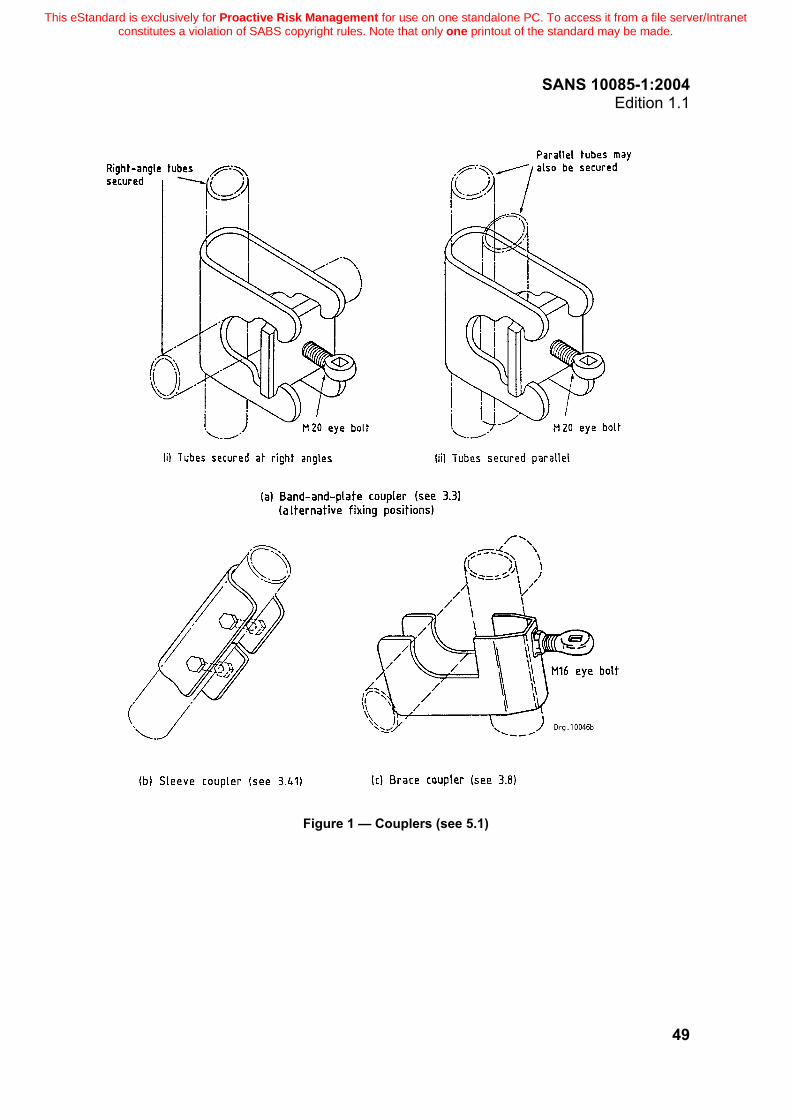
SANS 10085-1:2004 Edition 1.1
49
Figure 1 — Couplers (see 5.1)
This eStandard is exclusively for Proactive Risk Management for use on one standalone PC. To access it from a file server/Intranet constitutes a violation of SABS copyright rules. Note that only one printout of the standard may be made.

SANS 10085-1:2004 Edition 1.1
50
Figure 2 — Baseplates (see 3.5 and 5.3)
Figure 3 — Hop-up bracket (see 3.22, 5.8 and 10.19(a))
This eStandard is exclusively for Proactive Risk Management for use on one standalone PC. To access it from a file server/Intranet constitutes a violation of SABS copyright rules. Note that only one printout of the standard may be made.

SANS 10085-1:2004 Edition 1.1
51
Figu
re 4
(a) —
Tub
ular
ste
el in
depe
nden
t tie
d sc
affo
ldin
g (tu
be a
nd fi
tting
) (se
e 3.
24, 3
.52,
7.2
, 8.4
and
10.
10)
This eStandard is exclusively for Proactive Risk Management for use on one standalone PC. To access it from a file server/Intranet constitutes a violation of SABS copyright rules. Note that only one printout of the standard may be made.

SANS 10085-1:2004 Edition 1.1
52
Figu
re 4
(b) —
Tub
ular
ste
el in
depe
nden
t tie
d sc
affo
ldin
g (s
yste
m) (
see
3.24
, 7.2
, 8.4
, 10.
12 a
nd 1
1.10
)
This eStandard is exclusively for Proactive Risk Management for use on one standalone PC. To access it from a file server/Intranet constitutes a violation of SABS copyright rules. Note that only one printout of the standard may be made.
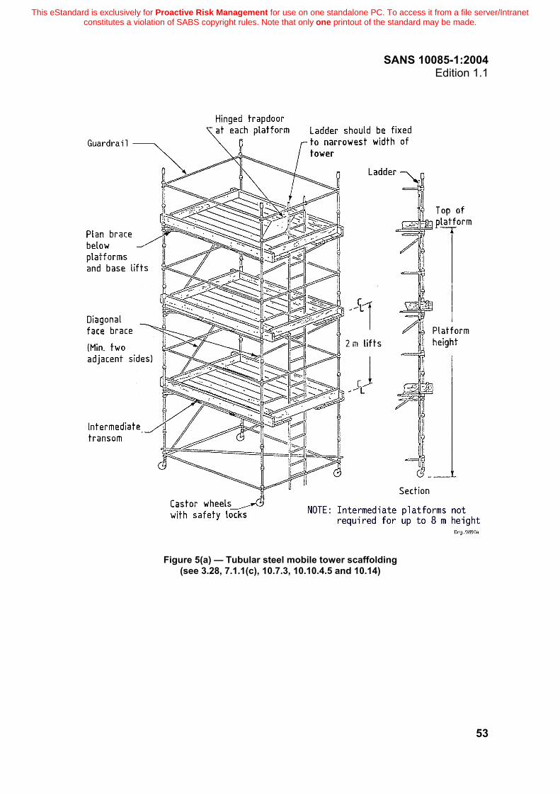
SANS 10085-1:2004 Edition 1.1
53
Figure 5(a) — Tubular steel mobile tower scaffolding (see 3.28, 7.1.1(c), 10.7.3, 10.10.4.5 and 10.14)
This eStandard is exclusively for Proactive Risk Management for use on one standalone PC. To access it from a file server/Intranet constitutes a violation of SABS copyright rules. Note that only one printout of the standard may be made.

SANS 10085-1:2004 Edition 1.1
54
Figure 5(b) — Tubular steel mobile tower (interlocking frame scaffolding) (see 3.28, 7.1.1(c), 10.7.3, 10.10.4.5, 10.11.4.1 and 10.14)
This eStandard is exclusively for Proactive Risk Management for use on one standalone PC. To access it from a file server/Intranet constitutes a violation of SABS copyright rules. Note that only one printout of the standard may be made.

SANS 10085-1:2004 Edition 1.1
55
Figure 6 — Typical temporarily-installed outrigger (cantilever beam) scaffolding (see 3.30, 5.13, 10.9 and 11.7)
This eStandard is exclusively for Proactive Risk Management for use on one standalone PC. To access it from a file server/Intranet constitutes a violation of SABS copyright rules. Note that only one printout of the standard may be made.

SANS 10085-1:2004 Edition 1.1
56
Figu
re 7
— P
utlo
g sc
affo
ldin
g (s
ee 3
.9, 3
.34,
7.1
.1(a
), 8.
4 an
d 10
.13)
This eStandard is exclusively for Proactive Risk Management for use on one standalone PC. To access it from a file server/Intranet constitutes a violation of SABS copyright rules. Note that only one printout of the standard may be made.

SANS 10085-1:2004 Edition 1.1
57
Figure 8 — Through tie and reveal tie across window opening (see 3.36, 10.5 and 10.10.3)
This eStandard is exclusively for Proactive Risk Management for use on one standalone PC. To access it from a file server/Intranet constitutes a violation of SABS copyright rules. Note that only one printout of the standard may be made.

SANS 10085-1:2004 Edition 1.1
58
Figure 9 — Trestles (see 3.51 and 10.16)
This eStandard is exclusively for Proactive Risk Management for use on one standalone PC. To access it from a file server/Intranet constitutes a violation of SABS copyright rules. Note that only one printout of the standard may be made.

SANS 10085-1:2004 Edition 1.1
59
Figure 10 — Knots for fibre ropes (see 6.3.3)
This eStandard is exclusively for Proactive Risk Management for use on one standalone PC. To access it from a file server/Intranet constitutes a violation of SABS copyright rules. Note that only one printout of the standard may be made.

SANS 10085-1:2004 Edition 1.1
60
Figure 11 — Frames for frame or tower scaffolding (see 3.19, 5.10.2, 10.11 and 11.9)
This eStandard is exclusively for Proactive Risk Management for use on one standalone PC. To access it from a file server/Intranet constitutes a violation of SABS copyright rules. Note that only one printout of the standard may be made.

SANS 10085-1:2004 Edition 1.1
61
Figure 12 — Typical staircase access to system scaffolding (see 10.8)
This eStandard is exclusively for Proactive Risk Management for use on one standalone PC. To access it from a file server/Intranet constitutes a violation of SABS copyright rules. Note that only one printout of the standard may be made.

SANS 10085-1:2004 Edition 1.1
62
Figure 13 — Pavement gantry and apron (fan) (see 10.20, 10.21 and 11.4.2)
This eStandard is exclusively for Proactive Risk Management for use on one standalone PC. To access it from a file server/Intranet constitutes a violation of SABS copyright rules. Note that only one printout of the standard may be made.

SANS 10085-1:2004 Edition 1.1
63
Figure 14 — Typical cantilever off-loading platform (see 10.22)
This eStandard is exclusively for Proactive Risk Management for use on one standalone PC. To access it from a file server/Intranet constitutes a violation of SABS copyright rules. Note that only one printout of the standard may be made.

SANS 10085-1:2004 Edition 1.1
64
Figure 15 — Typical hoist tower (see 10.23)
This eStandard is exclusively for Proactive Risk Management for use on one standalone PC. To access it from a file server/Intranet constitutes a violation of SABS copyright rules. Note that only one printout of the standard may be made.

SANS 10085-1:2004 Edition 1.1
65
Annex A (informative)
Example of scaffolding design calculations
Required scaffold: Medium duty construction scaffold (tubular steel system scaffolding), 60 m high Total number of platforms: Allowable number of working platforms (from table 5) = (2 × M) + (1 × VL)
Therefore, total number of platforms allowed (per 7.2.3) = 6 platforms
(i.e. 3 working + 3 non-working platforms) Mass of scaffold framework supported (per outside standard, per 2 m lift): Using scaffold tube standards and ledgers of average mass 5 kg/m for standards and 4 kg/m for ledgers (from table 2 and SANS 657-1): Standard : 2 m × 5 kg/m = 10 kg
2,5 m ledger : 2,5 × 4 kg/m = 10 kg
1,219 m ledger : 0,5 × 1,219 × 4 kg/m = 2,4 kg
Therefore, mass per 2 m lift = 10 + 10 + 2,4 = 22,4 kg
Therefore, mass for 30 lifts (as 60 m high) = 22,4 × 30 = 672 kg
Add approx. 10 % to mass value to allow for bracing, and round off to a practical number.
Therefore, total mass for framework = ± 750 kg Mass of platforms supported (per outside standard): Including toeboards, guardrail and kneerail, using 2,5 m steel boards at 18,5 kg/m, toeboard at 13,5 kg mass and toeboard clips at 2 kg mass each: Steel boards : 2,5 × 18,5 = 46,2 kg
Toeboard : 1 × 13,5 = 13,5 kg
Toeboard clip : 1 × 2 = 2,0 kg
2,5 m ledgers (guardrail and kneerail) : 2 × 10 kg = 20,0 kg
Therefore, self-mass per platform supported on an outside standard = 81,7kg
Mass of 6 levels of platforms = 6 × 81,7 kg = 490 kg
This eStandard is exclusively for Proactive Risk Management for use on one standalone PC. To access it from a file server/Intranet constitutes a violation of SABS copyright rules. Note that only one printout of the standard may be made.

SANS 10085-1:2004 Edition 1.1
66
Working loads: Calculate loads which will be carried per outside standard (where the materials are stacked against the outside of the platform). Total allowance per medium platform (from table 5) is 240 kg/m2, of which 80 kg/m2 (i.e. 1/3) is allowed for workmen and 160 kg/m2 (i.e. 2/3) is for materials. NOTE It is reasonable to assume that approximately 1/3 of the total imposed load is on the inner side of the platform (near the work face), and 2/3 of the total imposed load is due to the materials stacked on the outside of the platform. Many designers use this 1/3 and 2/3 allocation of imposed loading as it gives a conservative result. However, a more accurate calculation is to take 20 % of 1/3 plus 80 % of 2/3 of the imposed load (i.e. 60 % of the total imposed load) as being supported by the outside standard. Area of platform to be supported = 2,5 m × 1,15 m = 2,875 m²
Therefore, the imposed load of 2 × M class workingplatforms per outside standard
=
2 × 2,875 × 60 % × 240
=
828 kg
Add loading for one VL class platform, i.e. 80 kg/m2 (from table 5), equally divided between inside and outside supporting standard (equally divided, as no materials are stacked on a VL platform), i.e
1 × 2,875 × 50 % × 80 kg/m²
=
115 kg
Total loading: The total loading to be supported by an outside standard
= 750 kg (for framework) + 490 kg (for platforms) + 828 kg (imposed) + 115 kg (imposed)
= 2 183 kg force = 21,4 kN
This value is within the limit of 24 kN given in 9.1, and therefore acceptable. NOTE Using the 1/3 -
2/3 rule, the imposed load becomes 66,6 % × [(2 × 240 × 2,875) + (80 × 2,875)] = 1 073 kg, and the total calculated load becomes 2 313 kg force = 22,7 kN.
This eStandard is exclusively for Proactive Risk Management for use on one standalone PC. To access it from a file server/Intranet constitutes a violation of SABS copyright rules. Note that only one printout of the standard may be made.

SANS 10085-1:2004 Edition 1.1
67
Annex B (normative)
Basic checklist for scaffold inspections
Items to be inspected Detail or characteristic to be checked
Equipment Fitness for purpose Correct spacing of standards Firm fixing
Loading of scaffolding (see 7.2.3 and table 4 and 5)
Standards spaced to suit classification Permissible number of working platforms is known by user Total allowable number of platforms not exceeded
Foundations Ground Soleboards Baseplates Jacks
Ties Soundness of structure Sufficient ties Sound condition Tightness of ties
Bracing Complete lines Sufficient types Correct fitting
Platforms Boards properly supported Boards in good condition Trapdoors Toeboards Handrails Boards tied down
Access Ladders secured 900 mm above platform Ladders in good condition Properly supported
Mobiles Correct castors Height / width ratio correct Braced Brakes
Cantilever Design and sketch provided Checked to sketch
Signage Correct signs Correct positions
Special scaffolds (which are beyond the scope of this part of SANS 10085)
Designed and checked by specialist Type of material stated by the designers
This eStandard is exclusively for Proactive Risk Management for use on one standalone PC. To access it from a file server/Intranet constitutes a violation of SABS copyright rules. Note that only one printout of the standard may be made.

SANS 10085-1:2004 Edition 1.1
68
Annex C (informative)
Typical format for scaffold inspection register
Location/type of
scaffold Date of
inspection Faults found during inspection Date corrected Signature
Bibliography SANS 1169 (SABS 1169), Temporary stands. SANS 10333-1 (SABS 0333-1), Industrial rope access – Part 1: Worksite procedures. SANS 10333-2 (SABS 0333-2), Industrial rope access – Part 2: Training and certification procedures. SANS 10333-3 (SABS 0333-3), Industrial rope access – Part 3: Inspection, certification and manage-ment procedures for equipment.
© Standards South Africa
This eStandard is exclusively for Proactive Risk Management for use on one standalone PC. To access it from a file server/Intranet constitutes a violation of SABS copyright rules. Note that only one printout of the standard may be made.