metal scaffolding scaffold... · bs 1139-1.2, metal scaffolding – part 1: tubes – section 1.2...
TRANSCRIPT

raising standards worldwide™
NO COPYING WITHOUT BSI PERMISSION EXCEPT AS PERMITTED BY COPYRIGHT LAW
BSI British Standards
Metal scaffolding –Part 2: Couplers –Section 2.2: Aluminium couplers and special couplers in steel – Requirements and test methods
BS 1139-2.2:2009

BS 1139-2.2:2009 BRITISH STANDARD
Publishing and copyright informationThe BSI copyright notice displayed in this document indicates when the document was last issued.
© BSI 2009
ISBN 978 0 580 56969 2
ICS 91.220
The following BSI references relate to the work on this standard: Committee reference B/514 Draft for comment 09/30150058 DC
Publication historyFirst published January 1991Second (present) edition, October 2009
Amendments issued since publication
Date Text affected
BRITISH STANDARD
© BSI 2009 i
BS 1139-2.2:2009
ContentsForeword iii1 Scope 12 Normative references 13 Terms and definitions 14 Materials 35 Fittings 46 Aluminium right-angle, swivel and sleeve couplers 47 Steel putlog couplers 58 Steel putlogs and putlog adapters 59 Expanding joint pin 610 Reveal pins 611 Castors 712 Toe-board clips 713 Production 814 Product manual 815 Marking 8
AnnexesAnnex A (normative) Test methods for components 9Annex B (informative) Data for users of the permissive stress design method 15
Bibliography 16
List of figuresFigure 1 – Typical joint pin 2Figure 2 – Types of putlog couplers 2Figure 3 – Types of reveal pin 3Figure A.1 – Test arrangement for the slipping resistance of a putlog coupler 10Figure A.2 – Test arrangement for a putlog or a putlog assembly 11Figure A.3 – Test arrangement for lateral strength of a reveal tie assembly 13Figure A.4 – Test arrangement for a castor assembly 14
List of tablesTable 1 – Coupler types and test methods 4Table A.1 – Reference tubes for tests 9Table A.2 – Minimum number of tests 9Table B.1 – Safe working loads 15
Summary of pagesThis document comprises a front cover, an inside front cover, pages i to iv, pages 1 to 16, an inside back cover and a back cover.

BS 1139-2.2:2009
ii © BSI 2009
BRITISH STANDARD
This page deliberately left blank

BRITISH STANDARD
© BSI 2009 iii
BS 1139-2.2:2009
ForewordPublishing information
This British Standard is published by BSI and came into effect on 31 October 2009. It was prepared by Subcommittee B/514/21, Access and working scaffolds and their components (props, tubes and couplers) under the authority of Technical Committee B/514, Access and support equipment. A list of organizations represented on this committee can be obtained on request to its secretary.
Supersession
BS 1139-2.2:2009 supersedes BS 1139-2.2:1991, which is withdrawn.
Relationship with other publications
BS 1139, Metal scaffolding, was published in six parts:
• Part 1.1: Tubes – Specification for steel tube (superseded by BS EN 39:2001);
• Part 1.2: Tubes – Specification for aluminium tube;
• Part 2.1: Couplers – Specification for steel couplers, loose spigots and base-plates for use in working scaffolds and falsework made of steel tubes (superseded by BS EN 74-1:2005);
• Part 3: Specification for prefabricated mobile access and working towers (superseded by BS EN 1004:2004);
• Part 4: Specification for prefabricated steel splitheads and trestles;
• Part 5: Specification for materials, dimensions, design loads and safety requirements for service and working scaffolds made of prefabricated elements (superseded by BS EN 12810-1:2003);
• Part 6: Specification for prefabricated tower scaffolds outside the scope of BS EN 1004, but utilizing components from such systems.
Information about this document
This British Standard supplements BS EN 74-1 and significant reference is made to it.
BS 1139-2.2:1991 specified requirements for steel and aluminium alloy couplers and fittings. This edition covers right-angle, swivel and sleeve couplers made from aluminium, and a range of special couplers made from steel. For fittings no longer included in this standard, see:
• prEN 74-3 (non-adjustable baseplates); and
• BS EN 12810-2:2003, Annex B (adjustable baseplates).
The main changes from BS 1139-2.2:1991 are:
• the information is much more comprehensive and precise and gives more confidence in the components;
• reference to open-jointed tube is no longer included;
• minimum contents of a product manual are specified;
• requirements for putlogs are specified;
• the testing and assessment procedures are specified in greater detail.
Annex A specifies test methods for components to establish the characteristic values, typically failure.
Annex B specifies data for users of the permissive stress design method.
BS 1139-2.2:2009
iv © BSI 2009
BRITISH STANDARD
Presentational conventions
The provisions of this standard are presented in roman (i.e. upright) type. Its requirements are expressed in sentences in which the principal auxiliary verb is “shall”.
Commentary, explanation and general informative material is presented in smaller italic type, and does not constitute a normative element.
Contractual and legal considerations
This publication does not purport to include all the necessary provisions of a contract. Users are responsible for its correct application.
Compliance with a British Standard cannot confer immunity from legal obligations.
BRITISH STANDARD
© BSI 2009 1
BS 1139-2.2:2009
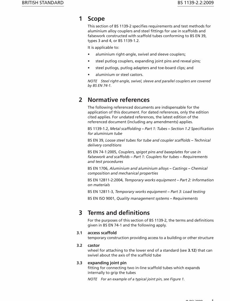
1 ScopeThis section of BS 1139-2 specifies requirements and test methods for aluminium alloy couplers and steel fittings for use in scaffolds and falsework constructed with scaffold tubes conforming to BS EN 39, types 3 and 4, or BS 1139-1.2.
It is applicable to:
• aluminium right-angle, swivel and sleeve couplers;
• steel putlog couplers, expanding joint pins and reveal pins;
• steel putlogs, putlog adapters and toe-board clips; and
• aluminium or steel castors.
NOTE Steel right-angle, swivel, sleeve and parallel couplers are covered by BS EN 74-1.
2 Normative referencesThe following referenced documents are indispensable for the application of this document. For dated references, only the edition cited applies. For undated references, the latest edition of the referenced document (including any amendments) applies.
BS 1139-1.2, Metal scaffolding – Part 1: Tubes – Section 1.2 Specification for aluminium tube
BS EN 39, Loose steel tubes for tube and coupler scaffolds – Technical delivery conditions
BS EN 74-1:2005, Couplers, spigot pins and baseplates for use in falsework and scaffolds – Part 1: Couplers for tubes – Requirements and test procedures
BS EN 1706, Aluminium and aluminium alloys – Castings – Chemical composition and mechanical properties
BS EN 12811-2:2004, Temporary works equipment – Part 2: Information on materials
BS EN 12811-3, Temporary works equipment – Part 3: Load testing
BS EN ISO 9001, Quality management systems – Requirements
3 Terms and definitionsFor the purposes of this section of BS 1139-2, the terms and definitions given in BS EN 74-1 and the following apply.
3.1 access scaffoldtemporary construction providing access to a building or other structure
3.2 castorwheel for attaching to the lower end of a standard (see 3.12) that can swivel about the axis of the scaffold tube
3.3 expanding joint pinfitting for connecting two in-line scaffold tubes which expands internally to grip the tubes
NOTE For an example of a typical joint pin, see Figure 1.
BS 1139-2.2:2009
2 © BSI 2009
BRITISH STANDARD
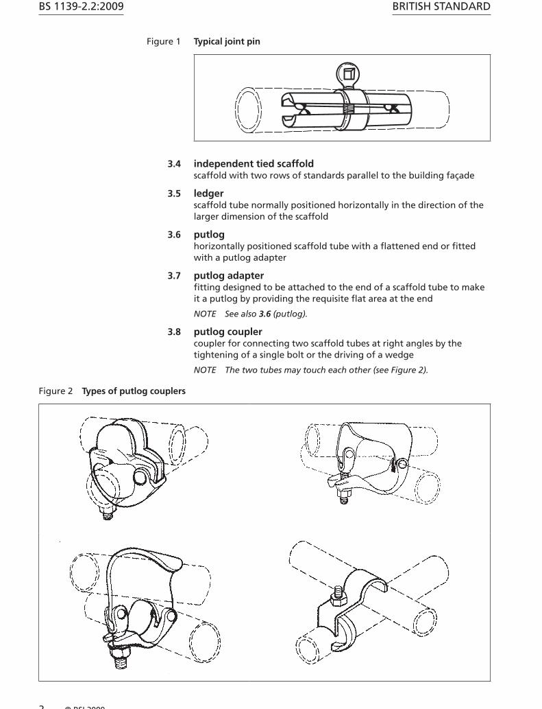
Figure 1 Typical joint pin
3.4 independent tied scaffoldscaffold with two rows of standards parallel to the building façade
3.5 ledgerscaffold tube normally positioned horizontally in the direction of the larger dimension of the scaffold
3.6 putloghorizontally positioned scaffold tube with a flattened end or fitted with a putlog adapter
3.7 putlog adapterfitting designed to be attached to the end of a scaffold tube to make it a putlog by providing the requisite flat area at the end
NOTE See also 3.6 (putlog).
3.8 putlog couplercoupler for connecting two scaffold tubes at right angles by the tightening of a single bolt or the driving of a wedge
NOTE The two tubes may touch each other (see Figure 2).
Figure 2 Types of putlog couplers
BRITISH STANDARD
© BSI 2009 3
BS 1139-2.2:2009
3.9 putlog scaffoldscaffold with a single row of standards parallel to the building façade and linked to it by putlogs
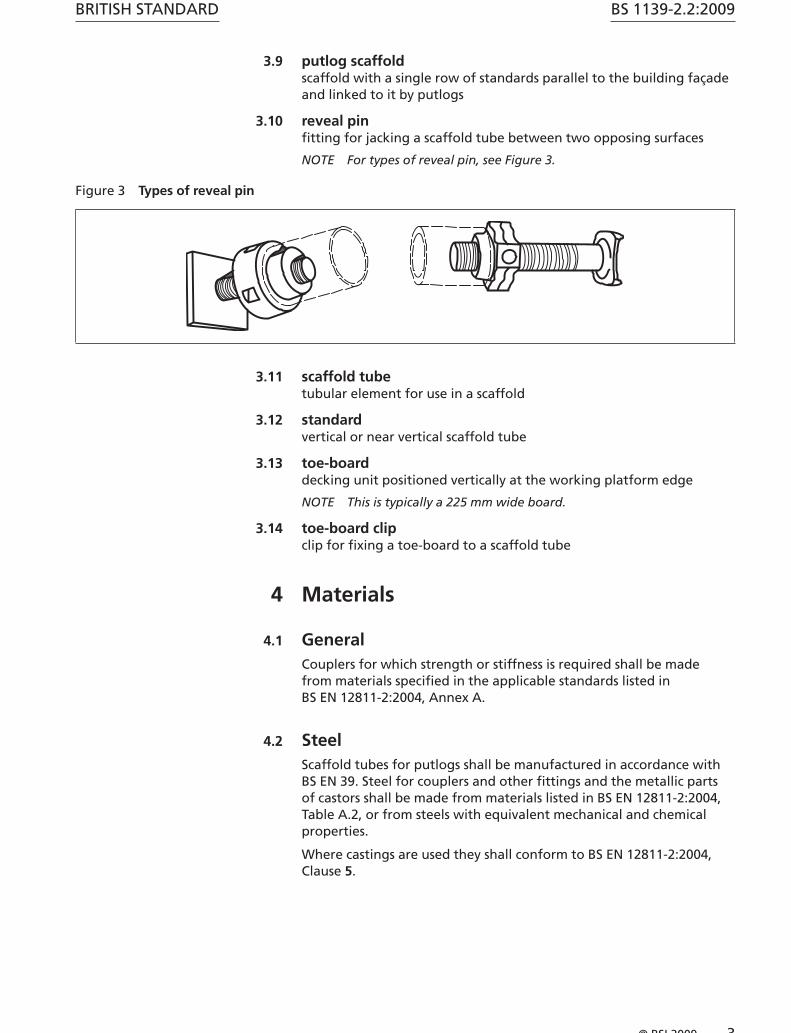
3.10 reveal pinfitting for jacking a scaffold tube between two opposing surfaces
NOTE For types of reveal pin, see Figure 3.
Figure 3 Types of reveal pin
3.11 scaffold tubetubular element for use in a scaffold
3.12 standardvertical or near vertical scaffold tube
3.13 toe-boarddecking unit positioned vertically at the working platform edge
NOTE This is typically a 225 mm wide board.
3.14 toe-board clipclip for fixing a toe-board to a scaffold tube
4 Materials
4.1 GeneralCouplers for which strength or stiffness is required shall be made from materials specified in the applicable standards listed in BS EN 12811-2:2004, Annex A.
4.2 SteelScaffold tubes for putlogs shall be manufactured in accordance with BS EN 39. Steel for couplers and other fittings and the metallic parts of castors shall be made from materials listed in BS EN 12811-2:2004, Table A.2, or from steels with equivalent mechanical and chemical properties.
Where castings are used they shall conform to BS EN 12811-2:2004, Clause 5.
BS 1139-2.2:2009
4 © BSI 2009
BRITISH STANDARD
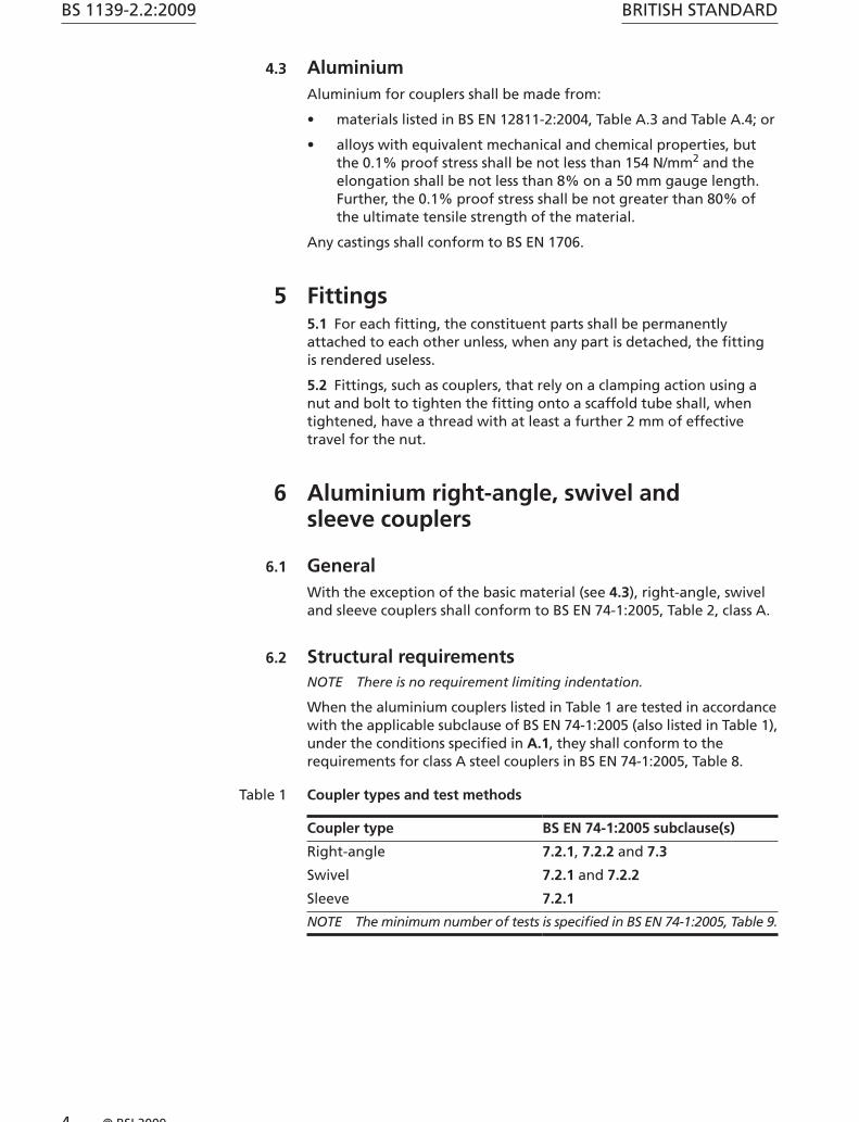
4.3 AluminiumAluminium for couplers shall be made from:
• materials listed in BS EN 12811-2:2004, Table A.3 and Table A.4; or
• alloys with equivalent mechanical and chemical properties, but the 0.1% proof stress shall be not less than 154 N/mm2 and the elongation shall be not less than 8% on a 50 mm gauge length. Further, the 0.1% proof stress shall be not greater than 80% of the ultimate tensile strength of the material.
Any castings shall conform to BS EN 1706.
5 Fittings5.1 For each fitting, the constituent parts shall be permanently attached to each other unless, when any part is detached, the fitting is rendered useless.
5.2 Fittings, such as couplers, that rely on a clamping action using a nut and bolt to tighten the fitting onto a scaffold tube shall, when tightened, have a thread with at least a further 2 mm of effective travel for the nut.
6 Aluminium right-angle, swivel and sleeve couplers
6.1 GeneralWith the exception of the basic material (see 4.3), right-angle, swivel and sleeve couplers shall conform to BS EN 74-1:2005, Table 2, class A.
6.2 Structural requirementsNOTE There is no requirement limiting indentation.
When the aluminium couplers listed in Table 1 are tested in accordance with the applicable subclause of BS EN 74-1:2005 (also listed in Table 1), under the conditions specified in A.1, they shall conform to the requirements for class A steel couplers in BS EN 74-1:2005, Table 8.
Table 1 Coupler types and test methods
Coupler type BS EN 74-1:2005 subclause(s)
Right-angle 7.2.1, 7.2.2 and 7.3
Swivel 7.2.1 and 7.2.2
Sleeve 7.2.1
NOTE The minimum number of tests is specified in BS EN 74-1:2005, Table 9.
BRITISH STANDARD
© BSI 2009 5
BS 1139-2.2:2009
7 Steel putlog couplers
7.1 GeneralA steel putlog coupler shall be such that the upstand over one of the tubes it connects is not greater than 6 mm.
7.2 Structural requirementsWhen tested in accordance with A.2, under the conditions specified in A.1, the characteristic slip resistance shall be not less than 6.0 kN.
8 Steel putlogs and putlog adapters
8.1 GeneralNOTE 1 A putlog is normally made by flattening one end of a piece of scaffold tubing but may be made by the attachment of a putlog adapter to a scaffold tube. There are no specific requirements for a putlog adapter in respect of independent use.
NOTE 2 A putlog is normally between 1 500 m and 1 950 m in length. The flat section at the end of a putlog enables it to rest on a flat part of the structure served, or be positioned vertically in a slot. A putlog adapter is only usable when properly attached to a scaffold tube. The requirements of 8.1 apply to a putlog or a putlog adapter attached to a length of scaffold tube.
8.1.1 Either a flat end shall be provided to enable the putlog to rest on a flat part of the structure served or be positioned in a slot, or, alternatively, a plain scaffold tube shall be converted into a putlog by fixing a putlog adapter to it.
8.1.2 Where a scaffold tube is flattened to create the flat section, the material used for the scaffold tube (see 4.2) shall have sufficient ductility to avoid any significant cracking.
NOTE Slight tearing of the material is acceptable.
8.1.3 The flat end of a putlog shall be able to transmit a force on the tubular section in a direction at right angles to the plane of the flat section below.
8.1.4 When a putlog adapter is a welded fabrication, only weldable steels shall be used.
8.1.5 The flat end of a putlog shall be not less than 50 mm wide over a length of 75 mm.
NOTE This flat end might be a forging.
8.2 Structural requirementsNOTE A putlog adapter is only usable when it is properly attached to a piece of scaffold tubing.
When tested in accordance with A.3, under the conditions specified in A.1, the characteristic shear capacity of the flat end of a putlog, or a scaffold tube fitted with a putlog adapter, shall be not less than 6.0 kN in a direction at 90° to the bearing surface, applied at 35 mm from the end of the putlog.
BS 1139-2.2:2009
6 © BSI 2009
BRITISH STANDARD
9 Expanding joint pin
9.1 GeneralNOTE Expanding joint pins are not intended for use in positions where they will be subjected to bending or axial tension. Gripping is not considered to provide any structural strength.
9.1.1 An expanding joint pin shall be capable of use with steel scaffold tubes conforming to BS EN 39 and aluminium scaffold tubes conforming to BS 1139-1.2, and shall be self-centering in respect of the scaffold tubes that it connects. Self-centering shall be achieved by a flange at its mid-point, forming two flat surfaces onto which the connected scaffold tubes can bear. These surfaces shall be at 90° to the centreline axis of the expanding joint pin and provide continuous contact over the cross-section of connected square-ended scaffold tubes (see Figure 1).
9.1.2 An expanding joint pin shall penetrate both scaffold tubes equally, by not less than 75 mm. The joint pin shall be capable of gripping the two scaffold tubes when expanded.
9.2 Structural requirementsThe shear resistance of an expanding joint pin shall be not less than 80% of the shear resistance of the scaffold tubes that it connects, as determined by calculation in which the following conditions are satisfied:
1 251 0
..
× ××
A f
A ftube ytube
pin ypinH (1)
where:
Atube is the cross-sectional area of the connected scaffold tube (mm2);
Apin is the cross-sectional area of that part of the spigot inside the scaffold tube (mm2);
fytube is the minimum yield strength of the scaffold tube (N/mm2);
fypin is the minimum yield strength of the spigot (N/mm2).
10 Reveal pins
10.1 GeneralNOTE 1 A reveal pin creates a compressive force in a scaffold tube set between two parallel surfaces. This reveal pin assembly can then provide an anchorage for a force at 90° to the axis (see Figure A.3).
NOTE 2 A reveal pin and its associated scaffold tube make up a reveal tie (see principle in A.4). In current practice such ties are assumed to have a safe working load of 3.5 kN, applied within 150 mm of an abutment.
NOTE 3 Each type of reveal pin is designed to work with one of the three tube thicknesses. If it is small enough to be used with another tube type, it might not give the same structural performance.
The scaffold tube shall be cut square and the reveal pin shall be provided with an annular projection at one end, onto which a scaffold
BRITISH STANDARD
© BSI 2009 7
BS 1139-2.2:2009
tube can bear. The bearing surface shall be at 90° to the centreline axis of the reveal pin and provide continuous contact over the cross-section of a scaffold tube.
The plate end of the reveal pin shall be square to its centreline axis and provide a symmetrical bearing area of not less than 60 cm2.
The jack shall be infinitely variable over its range. Once tightened, the adjustment shall be insensitive to the variations of any transverse load applied to the reveal pin and unaffected by vibration generated by, for example, a concrete vibrator.
10.2 Structural requirementsWhen tested in accordance with A.4, under the conditions specified in A.1, the assembly shall have a characteristic resistance of not less than 6.0 kN at 90° to the axis of the pin and at 150 mm away from the end without the reveal pin.
11 Castors
11.1 GeneralNOTE 1 A castor enables a scaffold construction (e.g. an access tower) to be relocated anywhere over a flat area, and, when static, to transmit all loads from above.
A castor shall be capable of being fixed to a vertical scaffold tube in such a way that it cannot be accidentally released. The castor shall be concentric with the scaffold tube and shall provide a bearing surface over the full cross-sectional area of the scaffold tube.
The eccentricity of the castor (axis of castor wheel to axis of scaffold tube) shall be not more than 64 mm. The spigot shall engage with the scaffold tube by at least 50 mm and shall have a fixing device to prevent the castor inadvertently becoming detached. The diameter of the wheel of the castor shall be not less than 127 mm. The castor shall have a wheel brake.
NOTE 2 The addition of a tyre is optional.
11.2 Structural requirementsWhen tested in accordance with A.5, under the conditions specified in A.1, a castor shall have a characteristic resistance to vertical load of not less than 7.2 kN.
12 Toe-board clipsNOTE It is assumed that toe-boards will be positioned inside the standards and that they have no structural function.
The top of a toe-board clip, when retaining the top of a board on edge, shall project above the board by not more than 7 mm. A clip shall accommodate boards whose thicknesses range from 30 mm to 65 mm.
A toe-board clip shall grip the toe-board firmly so that, under conditions of normal use, the toe-board cannot work itself free.
BS 1139-2.2:2009
8 © BSI 2009
BRITISH STANDARD
13 ProductionAn appropriate method of quality control conforming to BS EN ISO 9001 shall be implemented during production.
14 Product manualThe following information as a minimum shall be provided.
a) General:
• necessary information about lubrication and the condition of all working surfaces;
• conditions of all tests (see A.1);
• the specific type and thickness of scaffold tube(s) with which each fitting is compatible.
b) Castors:
• safe working load.
c) Reveal pins:
• the specified tightening torque.
15 MarkingEach component shall be marked by stamping with:
a) the number and year of this British Standard, i.e. BS 1139-2.2:2009 1);
b) the manufacturer’s name or trademark;
c) model number in letters or numbers or symbols;
d) sufficient information for unambiguous identification as a reference for future inspection.
Expanding joint pins, reveal pins and castors shall be marked with compatible scaffold tube types. In addition, each castor shall be marked with its safe working load in kilograms. Reveal pins shall be marked with the minimum tightening torque.
1) Marking BS 1139-2.2:2009 on or in relation to a product represents a manufacturer’s declaration of conformity, i.e. a claim by or on behalf of the manufacturer that the product meets the requirements of the standard. The accuracy of the claim is solely the claimant’s responsibility. Such a declaration is not to be confused with third-party certification of conformity.

BRITISH STANDARD
© BSI 2009 9
BS 1139-2.2:2009
Annex A (normative) Test methods for components
A.1 Conditions for all tests
A.1.1 Common methods
In addition to the conditions specified in A.1 to A.5, BS EN 74-1:2005, 7.1.2 to 7.1.10 apply.
A.1.2 Component condition
The condition of any components tested in A.2 to A.5 shall be recorded, with particular reference to the type of corrosion protection and the state of lubrication.
A.1.3 Reference tube
Unless otherwise specified, the reference tubes in Table A.1 shall be used in the tests specified in A.2 to A.5, as appropriate. Steel tubes shall be new and unused, and hot dip galvanized in accordance with BS EN 12811-2, class C2 corrosion resistance.
Table A.1 Reference tubes for tests
Reference Material Minimum yield strength
N/mm2
Wall thickness
mm
Wall thickness tolerance
mm
Notes
RTS4 Steel 235 4.0 ±0.40 BS EN 39, type 4
RTS5 Steel 235 3.2 ±0.32 BS EN 39, type 3
RTA2 Aluminium 255 4.47 ±0.56 BS 1139-1.2
A.1.4 Number of tests
Components shall be subjected to the minimum number of tests as specified in Table A.2.
Table A.2 Minimum number of tests
Type of component Type of test Number of tests Subclause
BS EN 74-1:2005:
Right-angle coupler Slipping resistance 5 or 10 A) 7.2.1
Failure force 5 7.2.2
Pull-apart force 5 7.3
Swivel coupler Slipping force 5 or 10 A) 7.2.1
Failure force 5 7.2.2
Sleeve coupler Slipping force 5 7.2.1
BS 1139-2.2:2009:
Putlog coupler Slipping force 5 A.2
Putlogs and putlog adapters Plate failure (shear) 5 A.3
Reveal pins Failure force (bending) 5 A.4
Castors Failure force (compression) 3 A.5A) 5 for aluminium and 10 for steel.

BS 1139-2.2:2009
10 © BSI 2009
BRITISH STANDARD
A.2 Test method for the slipping resistance of a putlog coupler
A.2.1 Principle
This test establishes the characteristic slipping resistance of a putlog coupler.
A.2.2 Test arrangement
Connect a vertical scaffold tube to a horizontal scaffold tube by tightening the putlog coupler onto the horizontal scaffold tube with the jaw holding the vertical scaffold tube. Support the vertical scaffold tube at its base and place horizontal restraints either side of the coupler, 500 mm apart. Apply a vertical force, P, to the horizontal scaffold tube at two symmetrical points, not more than 500 mm apart (see Figure A.1).
Tighten the screws to a torque of 50 Nm with a torque wrench with an accuracy of ±5% or better.
Figure A.1 Test arrangement for the slipping resistance of a putlog coupler
Key
1 Vertical scaffold tube
2 Horizontal scaffold tube
3 Lateral support for scaffold tube
b G 250 mm
m G 500 mm
BRITISH STANDARD
© BSI 2009 11
BS 1139-2.2:2009
A.2.3 Procedure
Apply a vertical force, P, at a rate of not greater than 2 mm per minute, measured at the point of application of the load. Terminate the test when either the coupler fractures, or the coupler will accept no further increase in load.
A.2.4 Records
Record the load deflection curve, the maximum test force, Pmax, and a description of the mode of failure.
A.2.5 Evaluation
Analyse the results statistically in accordance with BS EN 12811-3 to determine the 5% quantile value of the failure force, Pf,5%. Apply a partial safety factor, cR2, determined in accordance with BS EN 12811-3 or taken to be 1.25. The characteristic resistance, FS, equals Pf,5% / cR2.
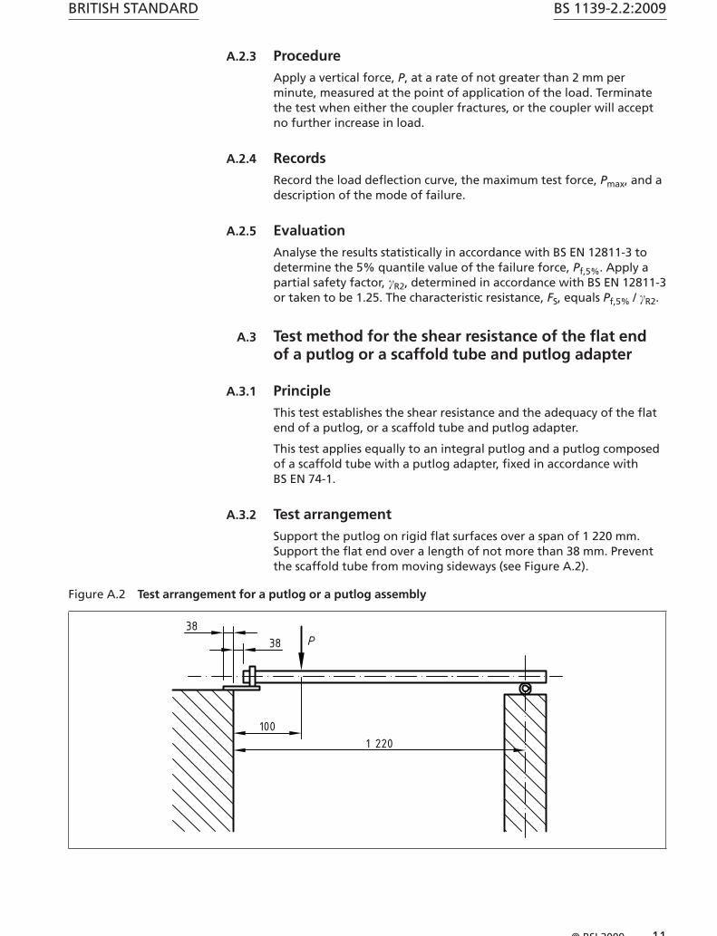
A.3 Test method for the shear resistance of the flat end of a putlog or a scaffold tube and putlog adapter
A.3.1 Principle
This test establishes the shear resistance and the adequacy of the flat end of a putlog, or a scaffold tube and putlog adapter.
This test applies equally to an integral putlog and a putlog composed of a scaffold tube with a putlog adapter, fixed in accordance with BS EN 74-1.
A.3.2 Test arrangement
Support the putlog on rigid flat surfaces over a span of 1 220 mm. Support the flat end over a length of not more than 38 mm. Prevent the scaffold tube from moving sideways (see Figure A.2).
Figure A.2 Test arrangement for a putlog or a putlog assembly

BS 1139-2.2:2009
12 © BSI 2009
BRITISH STANDARD
A.3.3 Procedure
Apply a vertical force, P, within 100 mm of the putlog support and increase it until there is substantial irrecoverable deflection or until the putlog will accept no further increase in load.
A.3.4 Records
Record the highest force which occurred, Pmax.
A.3.5 Evaluation
Analyse the results statistically in accordance with BS EN 12811-3 to determine the 5% quantile value of the failure load, Ps,5%. This is the characteristic shear strength of the end of a putlog or putlog assembly.
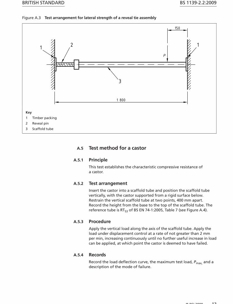
A.4 Test method for a reveal tie assembly
A.4.1 Principle
This test establishes the maximum lateral load capacity of a reveal tie assembly comprising a scaffold tube and a reveal pin.
A.4.2 Test arrangement
Assemble a scaffold tube with square-cut ends 1.8 m long with a reveal pin. Place the assembly horizontally between two parallel vertical unyielding surfaces. Insert timber packing not greater than 10 mm thick between the ends of the reveal pin assembly and the vertical surfaces (see Figure A.3).
Tighten the adjusting screw of the clamping device by applying the minimum torque specified by the manufacturer (see Clause 14).
A.4.3 Procedure
Apply a transverse load, P, at a distance of 150 mm from the end without the reveal pin. Apply this load under displacement control at a rate not greater than 2 mm per min. Increase the load continuously until the reveal pin assembly will accept no further increase in load.
A.4.4 Records
Record the load deflection curve, the maximum test load, Pmax, and a description of the mode of failure.
A.4.5 Evaluation
Analyse the results of the tests statistically in accordance with BS EN 12811-3 to determine the 5% quantile value of the failure load, Ps,5%.
Apply a partial safety factor, γR2, of 1.25. The characteristic lateral capacity, Ff,c, is given by:
PFs, %5
γ R2f,c= (2)
BRITISH STANDARD
© BSI 2009 13
BS 1139-2.2:2009
Figure A.3 Test arrangement for lateral strength of a reveal tie assembly
Key
1 Timber packing
2 Reveal pin
3 Scaffold tube
A.5 Test method for a castor
A.5.1 Principle
This test establishes the characteristic compressive resistance of a castor.
A.5.2 Test arrangement
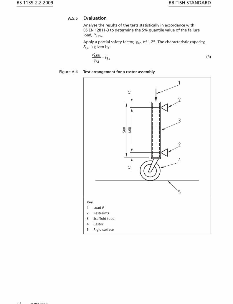
Insert the castor into a scaffold tube and position the scaffold tube vertically, with the castor supported from a rigid surface below. Restrain the vertical scaffold tube at two points, 400 mm apart. Record the height from the base to the top of the scaffold tube. The reference tube is RTS3 of BS EN 74-1:2005, Table 7 (see Figure A.4).
A.5.3 Procedure
Apply the vertical load along the axis of the scaffold tube. Apply the load under displacement control at a rate of not greater than 2 mm per min, increasing continuously until no further useful increase in load can be applied, at which point the castor is deemed to have failed.
A.5.4 Records
Record the load deflection curve, the maximum test load, Pmax, and a description of the mode of failure.
BS 1139-2.2:2009
14 © BSI 2009
BRITISH STANDARD
A.5.5 Evaluation
Analyse the results of the tests statistically in accordance with BS EN 12811-3 to determine the 5% quantile value of the failure load, Ps,5%.
Apply a partial safety factor, γR2, of 1.25. The characteristic capacity, Ff,c, is given by:
PFs, %5
γ R2f,c= (3)
Figure A.4 Test arrangement for a castor assembly
Key
1 Load P
2 Restraints
3 Scaffold tube
4 Castor
5 Rigid surface

BRITISH STANDARD
© BSI 2009 15
BS 1139-2.2:2009
Annex B (informative) Data for users of the permissive stress design methodTable B.1 gives information on safe working loads.
Table B.1 Safe working loads
Coupler Property Safe working load (kN)
Aluminium right-angle coupler Slipping force 6.1
Aluminium swivel coupler Slipping force 6.1
Aluminium sleeve coupler Slipping force 3.6
Putlog coupler Slipping force 0.63
Putlog and putlog adapter Shear force at the flat end of a putlog 3.6
Reveal tie Lateral capacity 3.0
Castor Vertical capacity 3.0
BS 1139-2.2:2009
16 © BSI 2009
BRITISH STANDARD
Bibliography
Standards publications
For dated references, only the edition cited applies. For undated references, the latest edition of the referenced document (including any amendments) applies.
BS EN 1004, Mobile access and working towers made of prefabricated elements – Materials, dimensions, design loads, safety and performance requirements
BS EN 12810-1, Façade scaffolds made of prefabricated components – Part 1: Product specifications
BS EN 12810-2:2003, Façade scaffolds made of prefabricated components – Part 2: Particular methods of structural design
prEN 74-3, Couplers, spigot pins and baseplates for use in falsework and scaffolds – Part 3: Plain baseplates and spigot pins – Requirements and test procedures

BSI is the independent national body responsible for preparing British Standards. It presents the UK view on standards in Europe and at the international level.
It is incorporated by Royal Charter.
British Standards Institution (BSI)
raising standards worldwide™
BSI Group Headquarters
389 Chiswick High Road London W4 4AL UK
Tel +44 (0)20 8996 9001Fax +44 (0)20 8996 7001www.bsigroup.com/standards
RevisionsBritish Standards are updated by amendment or revision. Users of BritishStandards should make sure that they possess the latest amendments oreditions.
It is the constant aim of BSI to improve the quality of our products andservices. We would be grateful if anyone finding an inaccuracy orambiguity while using this British Standard would inform the Secretary ofthe technical committee responsible, the identity of which can be foundon the inside front cover.
Tel: +44 (0)20 8996 9000 Fax: +44 (0)20 8996 7400BSI offers members an individual updating service called PLUS whichensures that subscribers automatically receive the latest editions ofstandards.
Buying standardsOrders for all BSI, international and foreign standards publicationsshould be addressed to BSI Customer Services.
Tel: +44 (0)20 8996 9001 Fax: +44 (0)20 8996 7001Email: [email protected] may also buy directly using a debit/credit card from the BSI Shopon the website www.bsigroup.com/shopIn response to orders for international standards, it is BSI policy tosupply the BSI implementation of those that have been publishedas British Standards, unless otherwise requested.
Information on standardsBSI provides a wide range of information on national, European andinternational standards through its Library.
Various BSI electronic information services are also available which givedetails on all its products and services. Contact the Information Centre.
Tel: +44 (0)20 8996 7111 Fax: +44 (0)20 8996 7048 Email: [email protected] members of BSI are kept up to date with standardsdevelopments and receive substantial discounts on the purchase priceof standards. For details of these and other benefits contact MembershipAdministration.
Tel: +44 (0)20 8996 7002 Fax: +44 (0)20 8996 7001 Email: [email protected] Information regarding online access to British Standards via BritishStandards Online can be found at www.bsigroup.com/BSOLFurther information about BSI is available on the BSI website atwww.bsigroup.com
CopyrightCopyright subsists in all BSI publications. BSI also holds the copyright, in the UK, of thepublications of the international standardization bodies. Except as permitted under theCopyright, Designs and Patents Act 1988 no extract may be reproduced, stored in a retrievalsystem or transmitted in any form or by any means – electronic, photocopying, recording orotherwise – without prior written permission from BSI. This does not preclude the free use, in the course of implementing the standard of necessarydetails such as symbols, and size, type or grade designations. If these details are to be used forany other purpose than implementation then the prior written permission of BSI must beobtained. Details and advice can be obtained from the Copyright & Licensing Manager.
Tel: +44 (0)20 8996 7070 Email: [email protected]