some basic command of nx 5
TRANSCRIPT

Chapter 4
Editing, Extruding, andRevolving Sketches
After completing this chapter, you will be able to:• Edit sketches using the editing tools.• Edit sketched entities by dragging.• Convert sketches into base features by extruding and revolving.• Hide and show the objects.• Rotate the view of the model dynamically in 3D space.• Change the view and the display of the models.
Learning Objectives

4-2 NX 5 for Designers
Eva
lua
tio
n C
hap
ter
Eva
lua
tio
n C
hap
ter
Eva
lua
tio
n C
hap
ter
Eva
lua
tio
n C
hap
ter
Eva
lua
tio
n C
hap
ter .
Do
no
t co
py
. D
o n
ot
cop
y.
Do
no
t co
py
. D
o n
ot
cop
y.
Do
no
t co
py .
V. V
. V
. V
. V i
sit
ww
wis
it w
ww
isit
ww
wis
it w
ww
isit
ww
w.c
adc
im.c
om
fo
r de
tail
s.c
adc
im.c
om
fo
r de
tail
s.c
adc
im.c
om
fo
r de
tail
s.c
adc
im.c
om
fo
r de
tail
s.c
adc
im.c
om
fo
r de
tail
s
EDITING SKETCHESEditing is a very important part of sketching in any design or manufacturing program. Youneed to edit the sketches during various stages of a design. NX provides you with a numberof tools that can be used to edit the sketched entities. These tools are discussed next.
Trimming Sketched Entities
This tool enables you to remove a portion of a sketch by chopping it off. Figure 4-1shows the sketched entities before trimming the entities and Figure 4-2 shows thesketch after trimming the entities. Note that when used on an isolated entity, thistool deletes it.
To trim the entities, invoke the Quick Trim tool from the Sketch Curve toolbar; the QuickTrim dialog box will be displayed, as shown in Figure 4-3.
Move the cursor over the portion to be trimmed; it will be highlighted in purple. Click totrim the highlighted portion. You will again be prompted to click on the entity to be trimmed.After trimming all entities, press ESC to exit this tool.
Figure 4-2 Sketch after trimming the entitiesFigure 4-1 Selecting the entities to be trimmed
Menu: Edit > Quick TrimToolbar: Sketch Curve > Quick Trim
Figure 4-3 The Quick Trim dialog box

Editing, Extruding, and Revolving Sketches 4-3
Eva
lua
tio
n C
hap
ter
Eva
lua
tio
n C
hap
ter
Eva
lua
tio
n C
hap
ter
Eva
lua
tio
n C
hap
ter
Eva
lua
tio
n C
hap
ter .
Do
no
t co
py
. D
o n
ot
cop
y.
Do
no
t co
py
. D
o n
ot
cop
y.
Do
no
t co
py .
V. V
. V
. V
. V i
sit
ww
wis
it w
ww
isit
ww
wis
it w
ww
isit
ww
w.c
adc
im.c
om
fo
r de
tail
s.c
adc
im.c
om
fo
r de
tail
s.c
adc
im.c
om
fo
r de
tail
s.c
adc
im.c
om
fo
r de
tail
s.c
adc
im.c
om
fo
r de
tail
s
Figure 4-7 Sketch after extending the entityFigure 4-6 Selecting the entity to be extended
To trim multiple entities, press and hold the left mouse button and drag the cursor over theentities to be trimmed. As you move the cursor over them, all the selected entities will betrimmed. Figure 4-4 shows multiple entities being trimmed by dragging the cursor overthem and Figure 4-5 shows the resulting sketch.
NX also allows you to select a sketched entity as the knife edge and then trim the other entitiesusing this cutting edge. To do so, choose the Boundary Curve button from the BoundaryCurve rollout; you will be prompted to select the boundary curve. Select the curve; this curvewill now become the knife edge. Next, choose the Curve to Trim button from the Curve to Trimrollout; you will be prompted to select the curve to be trimmed. Similarly, select other curvesthat intersect the boundary curve; the selected curves will be trimmed.
Extending Sketched Entities
The Quick Extend tool enables you to extend or lengthen an open sketchedentity up to the next entity that it intersects. Figure 4-6 shows the sketched entitybefore extending and Figure 4-7 shows the sketch after extending the entity. Note
Menu: Edit > Quick ExtendToolbar: Sketch Curve > Quick Extend
Figure 4-5 The resulting sketchFigure 4-4 Dragging the cursor to trim multipleentities

4-4 NX 5 for Designers
Eva
lua
tio
n C
hap
ter
Eva
lua
tio
n C
hap
ter
Eva
lua
tio
n C
hap
ter
Eva
lua
tio
n C
hap
ter
Eva
lua
tio
n C
hap
ter .
Do
no
t co
py
. D
o n
ot
cop
y.
Do
no
t co
py
. D
o n
ot
cop
y.
Do
no
t co
py .
V. V
. V
. V
. V i
sit
ww
wis
it w
ww
isit
ww
wis
it w
ww
isit
ww
w.c
adc
im.c
om
fo
r de
tail
s.c
adc
im.c
om
fo
r de
tail
s.c
adc
im.c
om
fo
r de
tail
s.c
adc
im.c
om
fo
r de
tail
s.c
adc
im.c
om
fo
r de
tail
s
that this tool will not work on an entity that does not intersect with any existing sketchedentity when extended.
You can also extend multiple entities by pressing and holding the left mouse button anddragging the cursor over them. All the other options of this tool are same as in the QuickTrim tool.
Mirroring Sketched Entities Using the Mirror Curve Tool
This tool enables you to create mirroredcopies of the selected sketched entities.Before invoking this tool, you need to draw
a line that will be the mirror line. This line will beconverted into a reference line after the mirroringoperation is completed. To mirror the sketchedentities, invoke the Mirror Curve tool; the MirrorCurve dialog box will be displayed, as shown inFigure 4-8. The Mirror Centerline button is chosenby default in the Mirror Centerline rollout. You willbe prompted to select a linear object or a plane forthe centerline. Select the mirror centerline. TheCurve to Mirror button will be chosen in the Curveto Mirror rollout and you will be prompted to selectthe curves to mirror. Select the curves to be mirroredand choose the OK button; the entities will be mirrored and the mirror line will be convertedinto the centerline. Figure 4-9 shows the mirror line and the entities selected to be mirroredand Figure 4-10 shows the sketch after mirroring the entities. The mirror line isautomatically converted into a reference line after mirroring.
Menu: Insert > Mirror CurveToolbar: Sketch Operations > Mirror Curve (Customize to add)
Figure 4-8 The Mirror Curve dialogbox
Figure 4-10 Sketch after mirroring the entitiesFigure 4-9 Mirror line and the entities selected tobe mirrored
Tip: After mirroring, if you select and drag any entity from the original portion ofthe sketch, the same change will also be reflected dynamically in its mirrored portion.However, this relationship ends if you delete the mirror centerline.

Editing, Extruding, and Revolving Sketches 4-5
Eva
lua
tio
n C
hap
ter
Eva
lua
tio
n C
hap
ter
Eva
lua
tio
n C
hap
ter
Eva
lua
tio
n C
hap
ter
Eva
lua
tio
n C
hap
ter .
Do
no
t co
py
. D
o n
ot
cop
y.
Do
no
t co
py
. D
o n
ot
cop
y.
Do
no
t co
py .
V. V
. V
. V
. V i
sit
ww
wis
it w
ww
isit
ww
wis
it w
ww
isit
ww
w.c
adc
im.c
om
fo
r de
tail
s.c
adc
im.c
om
fo
r de
tail
s.c
adc
im.c
om
fo
r de
tail
s.c
adc
im.c
om
fo
r de
tail
s.c
adc
im.c
om
fo
r de
tail
s
Transforming Sketched Entities
NX allows you to perform editing operations on the sketches using the Transformtool. To invoke this tool, choose Edit > Transform from the menu bar; theClass Selection dialog box will be displayed, as shown in Figure 4-11 and you will be
prompted to select objects to transform.
The Class Selection dialog box is used to selectthe objects to perform a particular operation. Thevarious rollouts in this dialog box are discussednext.
Objects RolloutThe options in this rollout are used to define theselection methods, which are discussed next.
Select ObjectsThis button is used to select the objects oneby one.
Select AllThis button is used to select all objects in thedrawing window such as sketching entities,datum coordinate systems, work planes, andso on.
Invert SelectionThis button is used to invert the selection.
Other Selection Methods RolloutThis rollout provides some additional selectionmethods.
Select by NameEnter the name of the sketch that you need to select in this text box and press theENTER key; the specified sketch will be selected.
Select ChainThis button is used to select the curves in chain. You need to select the first and the lastcurve from the sketch; all the sketched entities of the sketch (lines, arcs, and fillets)between these two specified curves will be selected.
Filters RolloutThis rollout is used to filter out the selection procedure. The options in this rollout havealready been discussed in Chapter 2.
Menu: Edit >TransformToolbar: Standard > Transform

4-6 NX 5 for Designers
Eva
lua
tio
n C
hap
ter
Eva
lua
tio
n C
hap
ter
Eva
lua
tio
n C
hap
ter
Eva
lua
tio
n C
hap
ter
Eva
lua
tio
n C
hap
ter .
Do
no
t co
py
. D
o n
ot
cop
y.
Do
no
t co
py
. D
o n
ot
cop
y.
Do
no
t co
py .
V. V
. V
. V
. V i
sit
ww
wis
it w
ww
isit
ww
wis
it w
ww
isit
ww
w.c
adc
im.c
om
fo
r de
tail
s.c
adc
im.c
om
fo
r de
tail
s.c
adc
im.c
om
fo
r de
tail
s.c
adc
im.c
om
fo
r de
tail
s.c
adc
im.c
om
fo
r de
tail
s
Select the entities to be transformed and choose the OK button; the Transformations dialogbox will be displayed, as shown in Figure 4-12.
Some of the transformation tools in this dialog box are discussed next and the rest will bediscussed in the later chapters.
Moving the Sketched Entities Using the Transformations Dialog BoxTo move the sketched entities using the Transformations dialog box, choose the Translatebutton; the dialog box will get modified and it will display two buttons, To A Point and Delta.You can move the entities from one point to another point using the To A Point button.These points could be any point, on the screen or the vertices of the sketch. Similarly, usingthe Delta option, you can move the entities by specifying the delta X, delta Y, and delta Zcoordinate values.
The steps required to move the entities using the To A Point option are discussed next.
1. Choose the Translate button and then the To A Point button in the Transformationsdialog box; the Point dialog box will be displayed and you will be prompted to selectobject to infer point.
2. Select the point from where you want to move the entities. You can select any point onthe screen or any inferred point from the sketch.
3. Next, you will be prompted to select object to infer point. Select the point up to whichyou need to move the selected sketch; the Transformations dialog box will be displayedagain, but with different options.
Figure 4-12 The Transformations dialog box

Editing, Extruding, and Revolving Sketches 4-7
Eva
lua
tio
n C
hap
ter
Eva
lua
tio
n C
hap
ter
Eva
lua
tio
n C
hap
ter
Eva
lua
tio
n C
hap
ter
Eva
lua
tio
n C
hap
ter .
Do
no
t co
py
. D
o n
ot
cop
y.
Do
no
t co
py
. D
o n
ot
cop
y.
Do
no
t co
py .
V. V
. V
. V
. V i
sit
ww
wis
it w
ww
isit
ww
wis
it w
ww
isit
ww
w.c
adc
im.c
om
fo
r de
tail
s.c
adc
im.c
om
fo
r de
tail
s.c
adc
im.c
om
fo
r de
tail
s.c
adc
im.c
om
fo
r de
tail
s.c
adc
im.c
om
fo
r de
tail
s
4. Select the Move option in the Transformations dialog box; the selected sketch will movefrom the first specified point to the second specified point and the Transformationsdialog box will be displayed again.
If you are not satisfied with the result of the transformation, you can choose the UndoLast - Avail button and then the Yes button in the Transformations dialog box to restorethe original sketch.
NoteIf the sketched entity to be moved is fixed due to constraints, then it will not move.
The steps required to move the entities using the Delta option are discussed next.
1. Choose the Translate button and then the Delta button in the Transformations dialogbox; the DXC, DYC, and DZC edit boxes will be displayed in this dialog box and you willbe prompted to specify the translation delta.
2. Enter the delta X, delta Y, and delta Z values to move the sketch and then choose the OKbutton; the Transformations dialog box will expand and display different options.
3. Select the Move option in the dialog box; the selected sketch will move up to thedistance specified in X, Y, and Z directions and the Transformations dialog box will bedisplayed again.
Copying the Sketched Entities Using the Transformations Dialog BoxYou can create single or multiple copies of the selected sketched entities using theTransformations dialog box. This process is similar to that of moving the sketched entities.The only difference is that instead of choosing the Move button in points 3 and 4 of theprevious section, you need to choose the Copy button. To make multiple copies, continuechoosing the Copy button. Alternatively, you can choose the Multiple Copies - Avail buttonand enter the value of the number of copies in the modified Transformations dialog box.
Creating Scaled Copies Using the Transformations Dialog BoxThe Scale option allows you to create scaled copies of the selected sketched entities. If required,you can also scale the sketched entities nonuniformly in the X, Y, and Z directions.
The steps required to scale the sketched entities using the Transformations dialog box arediscussed next.
1. Choose Edit > Transform from the menu bar and select the entities using the ClassSelection dialog box. Choose the OK button in this dialog box; the Transformationsdialog box will be displayed.
2. Choose the Scale button in the Transformations dialog box; the Point dialog box will bedisplayed and you will be prompted to select the object to infer point.
3. Select the base point of the scaling in the drawing window. You can select any point on

4-8 NX 5 for Designers
Eva
lua
tio
n C
hap
ter
Eva
lua
tio
n C
hap
ter
Eva
lua
tio
n C
hap
ter
Eva
lua
tio
n C
hap
ter
Eva
lua
tio
n C
hap
ter .
Do
no
t co
py
. D
o n
ot
cop
y.
Do
no
t co
py
. D
o n
ot
cop
y.
Do
no
t co
py .
V. V
. V
. V
. V i
sit
ww
wis
it w
ww
isit
ww
wis
it w
ww
isit
ww
w.c
adc
im.c
om
fo
r de
tail
s.c
adc
im.c
om
fo
r de
tail
s.c
adc
im.c
om
fo
r de
tail
s.c
adc
im.c
om
fo
r de
tail
s.c
adc
im.c
om
fo
r de
tail
s
Figure 4-13 Uniformly scaled entities
the screen or any inferred point from the sketch. On doing so, the modifiedTransformations dialog box will be displayed.
4. Enter the scale factor in the Scale edit box. If you need to scale the sketched entitiesnonuniformly, choose the Non-uniform Scale button; the dialog box will expand anddisplay the edit boxes to specify the scale factor in the X, Y, and Z directions.
5. After entering the required values, choose OK; the Transformations dialog box willexpand. Choose the Copy button; the scaled copy of the selected entities will be displayed.Figure 4-13 shows the uniformly scaled copy of the original sketch. The scale factor is1.5.
Rotating About a Point Using the Transformations Dialog BoxThe Rotate About a Point option allows you to rotate the selected sketched entities arounda specified point.
The steps required to rotate the selected entities using the Rotate About a Point option arediscussed next.
1. Choose Edit > Transform from the menu bar and select the entities using the ClassSelection dialog box. Then, choose the OK button; the Transformations dialog box willbe displayed.
2. Choose the Rotate About a Point button in the Transformations dialog box; the Pointdialog box will be displayed and you will be prompted to select the object to infer point.
3. Select the rotation center point in the drawing window. You can select any point on thescreen or any inferred point from the sketch. On doing so, the modified Transformationsdialog box will be displayed.
4. Enter the rotation angle in the Angle edit box. To rotate the sketched entities arbitrarilyusing two points, choose the Two Point Method button; the Point dialog box will bedisplayed and you will be prompted to select point 1. This point will be the start angle ofthe rotation. The angle will be measured from the rotation center point.

Editing, Extruding, and Revolving Sketches 4-9
Eva
lua
tio
n C
hap
ter
Eva
lua
tio
n C
hap
ter
Eva
lua
tio
n C
hap
ter
Eva
lua
tio
n C
hap
ter
Eva
lua
tio
n C
hap
ter .
Do
no
t co
py
. D
o n
ot
cop
y.
Do
no
t co
py
. D
o n
ot
cop
y.
Do
no
t co
py .
V. V
. V
. V
. V i
sit
ww
wis
it w
ww
isit
ww
wis
it w
ww
isit
ww
w.c
adc
im.c
om
fo
r de
tail
s.c
adc
im.c
om
fo
r de
tail
s.c
adc
im.c
om
fo
r de
tail
s.c
adc
im.c
om
fo
r de
tail
s.c
adc
im.c
om
fo
r de
tail
s
Figure 4-14 Original sketch and its rotated copy
5. Next, you will be prompted to select point 2. This point will define the angle of rotation.On selecting point 2, the Transformations dialog box will be displayed again.
6. Choose the Move button to rotate the original entities and the Copy button if you needto create a rotated copy of the original entities. If you choose the Multiple Copies -Avail button, multiple copies will be created. You can specify the number of copies in themodified Transformations dialog box. Figure 4-14 shows the original sketch along witha rotated copy created using the Two Point Method button.
Mirroring Entities Using the Transformations Dialog BoxThe Transformations dialog box allows you to mirror the sketched entities using threemethods. These methods are discussed next.
Mirroring Using Two PointsInvoke the Transformations dialog box and choose the Mirror Through a Line button;the Transformations dialog box will get modified. From the modified dialog box, choosethe Two Points button; the Point dialog box will be displayed. Specify two points on thescreen to define an imaginary line about which the sketch will be mirrored. Then, choosethe Move button in the Transformations dialog box if you need to delete the originalsketch after mirroring it. Choose the Copy button, if you need to retain the originalsketch along with the mirrored copy.
Mirroring Using an Existing LineInvoke the Transformations dialog box and choose the Mirror Through a Line button;the Transformations dialog box will be modified. From the modified dialog box, choosethe Existing Line button; the Transformations dialog box will be modified again andyou will be prompted to select the line to mirror about. Select the line about which thesketch will be mirrored and choose the Move or the Copy button.
Mirroring Using a Point and a VectorInvoke the Transformations dialog box and choose the Mirror Through a Line button;the Transformations dialog box will be modified. From the modified dialog box, choosethe Point and Vector button; the Point dialog box will be displayed and you will be

4-10 NX 5 for Designers
Eva
lua
tio
n C
hap
ter
Eva
lua
tio
n C
hap
ter
Eva
lua
tio
n C
hap
ter
Eva
lua
tio
n C
hap
ter
Eva
lua
tio
n C
hap
ter .
Do
no
t co
py
. D
o n
ot
cop
y.
Do
no
t co
py
. D
o n
ot
cop
y.
Do
no
t co
py .
V. V
. V
. V
. V i
sit
ww
wis
it w
ww
isit
ww
wis
it w
ww
isit
ww
w.c
adc
im.c
om
fo
r de
tail
s.c
adc
im.c
om
fo
r de
tail
s.c
adc
im.c
om
fo
r de
tail
s.c
adc
im.c
om
fo
r de
tail
s.c
adc
im.c
om
fo
r de
tail
s
prompted to select the object to infer point. Select a point on the screen or an inferredpoint from the sketch; the Vector dialog box will be displayed. To mirror about theX-axis, choose the XC Axis button. Similarly, to mirror about the Y-axis, choose the YCAxis button and choose the Move or the Copy button.
Editing Sketched Entities by DraggingYou can also edit the sketched entities by dragging them. Depending upon the type of entityselected and the point of selection, the object will be moved or stretched. For example, if youselect a line at any point other than the endpoints and drag the mouse, the line will bemoved. However, if you select a line at its endpoint, it will be stretched to a new size. Similarly, ifyou select an arc at its circumference or its endpoints, it will be stretched. But if you select thearc at its center point, it will be moved. Therefore, editing the sketched entities by draggingdepends entirely upon their selection points. The following table gives the details of theoperation that will be performed when you drag various entities. Note that while editing thesketched entities using the keypoints, all the related entities will also be moved or stretched.
Entity Selection point Operation
Circle On circumference Stretch
Center point Move
Arc On circumference/endpoints Stretch
Center point Move
Isolated line or multiple Anywhere other than the Movelines selected together endpoints
Endpoints Stretch
Curve Any point other than the Movekeypoints
Keypoints Stretch
Rectangle All lines selected together Move
Any one line or any endpoint Stretch
Ellipse Anywhere on the circumference Moveor center point
EXITING THE SKETCHER ENVIRONMENTAfter drawing and dimensioning the sketch, you need to exit theSketcher environment and invoke the Modeling environment to convert the

Editing, Extruding, and Revolving Sketches 4-11
Eva
lua
tio
n C
hap
ter
Eva
lua
tio
n C
hap
ter
Eva
lua
tio
n C
hap
ter
Eva
lua
tio
n C
hap
ter
Eva
lua
tio
n C
hap
ter .
Do
no
t co
py
. D
o n
ot
cop
y.
Do
no
t co
py
. D
o n
ot
cop
y.
Do
no
t co
py .
V. V
. V
. V
. V i
sit
ww
wis
it w
ww
isit
ww
wis
it w
ww
isit
ww
w.c
adc
im.c
om
fo
r de
tail
s.c
adc
im.c
om
fo
r de
tail
s.c
adc
im.c
om
fo
r de
tail
s.c
adc
im.c
om
fo
r de
tail
s.c
adc
im.c
om
fo
r de
tail
s
sketch into a feature. To exit the Sketcher environment, choose the Finish Sketch button inthe Sketcher toolbar. On exiting the Sketcher environment and entering theModeling environment, you will notice that the Sketch Curve and Sketch Constraints toolbarsare replaced by the Feature and Feature Operation toolbars. Also, the dimensions of thesketch are hidden. Note that the current view will change to the Trimetirc view.
As mentioned in the earlier chapters, most designs are a combination of various sketched,placed, and reference features. The first feature, generally, is a sketched feature. Already youhave learned to draw sketches for these base features and add constraints and dimensions tothem. After drawing and dimensioning a sketch, you need to convert it into the base feature.NX provides you with a number of tools such as Extrude, Revolve, and so on to convert thesebase sketches into base features. In this chapter, you will learn to use the Extrude andRevolve tools. The remaining tools will be discussed in the later chapters. The base featuresare created in the Modeling environment.
CHANGING THE VIEW OF THE SKETCHSometimes you need to change the view of the sketch for better visualization. To change theview, choose the down arrow on the right of the Trimetric button in the View toolbar; aflyout will be displayed with various view options. Select the required view from this flyout;the current view will be changed to the selected view.
CREATING BASE FEATURES BY EXTRUDING
Extrude is defined as the process of creating a feature from a sketch by adding thematerial along the direction normal to the sketch or any other specified direction.Figure 4-15 shows the Isometric view of a closed sketch and Figure 4-16 shows the
extruded feature created using this sketch.
When you invoke the Extrude tool, the Extrude dialog box will be displayed, as shown inFigures 4-17. You will be prompted to select the planar face to sketch or the section geometry tobe extruded. If you select the sketch at this stage, the preview of the extruded feature createdusing the default values will be displayed on the screen. If you select the sketch plane, theSketcher environment will be invoked. Draw the sketch and exit the Sketcher environment; thepreview of the extruded feature will be displayed in the Modeling environment.
Figure 4-15 Sketch for the extrude feature Figure 4-16 Resulting extruded feature
Menu: Insert > Design Feature > ExtrudeToolbar: Feature > Extrude

4-12 NX 5 for Designers
Eva
lua
tio
n C
hap
ter
Eva
lua
tio
n C
hap
ter
Eva
lua
tio
n C
hap
ter
Eva
lua
tio
n C
hap
ter
Eva
lua
tio
n C
hap
ter .
Do
no
t co
py
. D
o n
ot
cop
y.
Do
no
t co
py
. D
o n
ot
cop
y.
Do
no
t co
py .
V. V
. V
. V
. V i
sit
ww
wis
it w
ww
isit
ww
wis
it w
ww
isit
ww
w.c
adc
im.c
om
fo
r de
tail
s.c
adc
im.c
om
fo
r de
tail
s.c
adc
im.c
om
fo
r de
tail
s.c
adc
im.c
om
fo
r de
tail
s.c
adc
im.c
om
fo
r de
tail
s
Extrude Dialog Box OptionsThe options in this dialog box are discussed next.
Section RolloutThe options in this rollout are used to sketch the section or select the section. By default,both the Sketch Section and Curve buttons will be chosen in this rollout and you will beprompted to select the planar face to sketch or the section geometry to be extruded. Theseoptions are discussed next.
Sketch SectionThis button is used to draw the sketch for extrusion. When you choose this button, theCreate Sketch dialog box will be displayed and you will be prompted to select the objectfor the sketch plane. You can select a datum plane or the face of a solid body as thesketching plane.
CurveBy default, this button is also chosen from the Section rollout and it is used to select thealready drawn section sketch.
Figure 4-17 The Extrude dialog box

Editing, Extruding, and Revolving Sketches 4-13
Eva
lua
tio
n C
hap
ter
Eva
lua
tio
n C
hap
ter
Eva
lua
tio
n C
hap
ter
Eva
lua
tio
n C
hap
ter
Eva
lua
tio
n C
hap
ter .
Do
no
t co
py
. D
o n
ot
cop
y.
Do
no
t co
py
. D
o n
ot
cop
y.
Do
no
t co
py .
V. V
. V
. V
. V i
sit
ww
wis
it w
ww
isit
ww
wis
it w
ww
isit
ww
w.c
adc
im.c
om
fo
r de
tail
s.c
adc
im.c
om
fo
r de
tail
s.c
adc
im.c
om
fo
r de
tail
s.c
adc
im.c
om
fo
r de
tail
s.c
adc
im.c
om
fo
r de
tail
s
Figure 4-18 Preview of the symmetric extrusion
Direction RolloutBy default, the direction of extrusion will be normal to the selected section. The buttons inthis rollout are used to define the direction of extrusion. These options are discussed next.
Vector ConstructorIf you choose this button, the Vector dialog box will be displayed. You can specify theextrude direction using this dialog box.
Inferred Vector Drop-down listThis drop-down list is used to specify the direction of extrusion. The default direction isnormal to the selected section.
Reverse DirectionThis button is chosen to flip the current extrusion direction.
Limits RolloutThe options in this rollout are used to specify the start and termination of the extrusion.These options are discussed next.
Start Drop-down ListThis drop-down list allows you to specify the start point of the extrusion. You can select theValue and Symmetric Value options from this drop-down list. The Value option allows youto specify the distance from the sketching plane at which the extruded feature will start. Youneed to enter this value in the Distance edit box. If you enter a positive value, it will be takenas the offset value between the sketch and the start of the extrusion feature. If you enter 0,the extruded feature will start from the sketch plane. If you enter a negative value, theextruded feature will start from below the sketch plane. The Symmetric Value option allowsyou to extrude the sketch symmetrically in both the directions of the current sketchingplane. When you select this option, the edit boxes on the right of the Start and the End editboxes will show identical values and the preview will also be modified dynamically.Figure 4-18 shows the preview of a sketch being extruded symmetrically in both the directions.
End Drop-down ListThis drop-down list allows you to specify the extrusion termination in thedirection of extrusion. For the base feature, only the Value and Symmetric Value optionswill be available in this drop-down list. By default, the Value option will be selected, andthe value entered last will be displayed in the Distance edit box. As a result, the sketch

4-14 NX 5 for Designers
Eva
lua
tio
n C
hap
ter
Eva
lua
tio
n C
hap
ter
Eva
lua
tio
n C
hap
ter
Eva
lua
tio
n C
hap
ter
Eva
lua
tio
n C
hap
ter .
Do
no
t co
py
. D
o n
ot
cop
y.
Do
no
t co
py
. D
o n
ot
cop
y.
Do
no
t co
py .
V. V
. V
. V
. V i
sit
ww
wis
it w
ww
isit
ww
wis
it w
ww
isit
ww
w.c
adc
im.c
om
fo
r de
tail
s.c
adc
im.c
om
fo
r de
tail
s.c
adc
im.c
om
fo
r de
tail
s.c
adc
im.c
om
fo
r de
tail
s.c
adc
im.c
om
fo
r de
tail
s
will be extruded only in the specified direction. Note that you need to enter a positivevalue in the Distance edit box.
Figure 4-19 shows the preview of the extrusion in only one direction and Figure 4-20shows the preview of the extrusion with different values in both directions. In this figure,the extrusion value in the upward direction is 10 and in the downward direction is -5.
NoteThe other extrusion termination options are discussed in the next chapter.
Boolean RolloutOptions in this rollout allow you to select the boolean operation that you need to perform.These options in this rollout are discussed in the next chapter.
Draft RolloutThe options in this rollout are used to specify a draft angle to the extrusion feature. Theoptions in this area will be available only when you select the section to extrude. Various draftoptions in this rollout are discussed next.
Angle Edit boxThis edit box allows you to specify the draft angle.
Draft Drop-down ListThis drop-down list allows you to specify the type of draft to be applied to the feature.The options in this area are discussed next.
From Start LimitThis option adds the draft from the start section to the end section of the extrudedfeature. As a result, the dimension of the feature at the start section is the same asthat of the original sketch and it tapers toward the end section. Figure 4-21 shows the
Figure 4-20 Preview of the extrusion in twoopposite directions with different values
Figure 4-19 Preview of the extrusion in only onedirection
Tip: You can also use the start and end drag handles in the preview of the extrudedfeature to modify the extrusion values in the start and end directions.

Editing, Extruding, and Revolving Sketches 4-15
Eva
lua
tio
n C
hap
ter
Eva
lua
tio
n C
hap
ter
Eva
lua
tio
n C
hap
ter
Eva
lua
tio
n C
hap
ter
Eva
lua
tio
n C
hap
ter .
Do
no
t co
py
. D
o n
ot
cop
y.
Do
no
t co
py
. D
o n
ot
cop
y.
Do
no
t co
py .
V. V
. V
. V
. V i
sit
ww
wis
it w
ww
isit
ww
wis
it w
ww
isit
ww
w.c
adc
im.c
om
fo
r de
tail
s.c
adc
im.c
om
fo
r de
tail
s.c
adc
im.c
om
fo
r de
tail
s.c
adc
im.c
om
fo
r de
tail
s.c
adc
im.c
om
fo
r de
tail
s
preview of the extruded feature drafted using this option. It is evident in this figurethat the top section of the extruded feature is the same as that of the original sketchand the feature tapers as it goes toward the bottom section.
From SectionThis option adds the taper that is aligned with the profile, as shown in Figure 4-22.
From Section - Symmetric AngleThis option is available only when you select the Symmetric Value option from theLimits rollout or specify the values in both the start and the end directions. Thisoption adds a symmetric taper in both directions of the sketch, as shown in Figure 4-23.In this draft type, if the distance value in one of the directions is more than the other,the section in that direction will also be smaller in size.
From Section - Matched EndsThis option is also available only when you select the Symmetric Value option fromthe Limits rollout or specify the values in both the start and the end directions. Thisoption tapers the model such that the end sections in both the directions are ofsimilar size, irrespective of the distance values in both directions, as shown inFigure 4-24.
Figure 4-22 Preview of the tapered extrusionusing the From Section option
Figure 4-21 Preview of the tapered extrusionusing the From Start Limit option
Figure 4-24 Preview of the extrusion taperedusing the From Section - Matched Ends option
Figure 4-23 Preview of the extrusion taperedusing the From Section - Symmetric Angle option

4-16 NX 5 for Designers
Eva
lua
tio
n C
hap
ter
Eva
lua
tio
n C
hap
ter
Eva
lua
tio
n C
hap
ter
Eva
lua
tio
n C
hap
ter
Eva
lua
tio
n C
hap
ter .
Do
no
t co
py
. D
o n
ot
cop
y.
Do
no
t co
py
. D
o n
ot
cop
y.
Do
no
t co
py .
V. V
. V
. V
. V i
sit
ww
wis
it w
ww
isit
ww
wis
it w
ww
isit
ww
w.c
adc
im.c
om
fo
r de
tail
s.c
adc
im.c
om
fo
r de
tail
s.c
adc
im.c
om
fo
r de
tail
s.c
adc
im.c
om
fo
r de
tail
s.c
adc
im.c
om
fo
r de
tail
s
From Section - Asymmetric AngleThis option is also available only when you select the Symmetric Value option fromthe Limits rollout or specify the values in both the start and the end directions. Thisoption adds different tapers in both directions of the sketch, as shown in Figure 4-25.When you select this option, the Front Angle and Back Angle edit boxes will beavailable in the Draft rollout. The front and back angle values will be applied at thefront and back sides of the sketching planes used to create the extruded feature.
Offset RolloutNX also allows you to create thin base features by extruding open or closed sketches. Forexample, refer to the closed sketch shown in Figure 4-26. A thin feature created using thissketch is shown in Figure 4-27. Similarly, Figure 4-28 shows an open sketch and Figure 4-29shows the resulting thin feature.
If you need to use a closed sketch for creating a thin feature, then it is recommended thatthere should not be nested closed sketch in the main sketch. To create thin features, selectthe Offset rollout in the Extrude dialog box; the Offset drop-down list will be displayed.This drop-down list contains three offset methods. These methods are discussed next.
Figure 4-25 Preview of the extrusiontapered using the Asymmetric option
Figure 4-27 Isometric view of the resulting thinextruded feature
Figure 4-26 Top view of a single closed sketch

Editing, Extruding, and Revolving Sketches 4-17
Eva
lua
tio
n C
hap
ter
Eva
lua
tio
n C
hap
ter
Eva
lua
tio
n C
hap
ter
Eva
lua
tio
n C
hap
ter
Eva
lua
tio
n C
hap
ter .
Do
no
t co
py
. D
o n
ot
cop
y.
Do
no
t co
py
. D
o n
ot
cop
y.
Do
no
t co
py .
V. V
. V
. V
. V i
sit
ww
wis
it w
ww
isit
ww
wis
it w
ww
isit
ww
w.c
adc
im.c
om
fo
r de
tail
s.c
adc
im.c
om
fo
r de
tail
s.c
adc
im.c
om
fo
r de
tail
s.c
adc
im.c
om
fo
r de
tail
s.c
adc
im.c
om
fo
r de
tail
s
Two-SidedThis option is used to create a thin feature by offsetting the sketch in two directions.Select this option; the Start and End edit boxes will be displayed. If you enter thepositive value in the End edit box, the sketch will offset outward and vice-versa.Figure 4-30 shows the preview of a thin feature with an offset only in the end directionand Figure 4-31 shows the preview of the same feature with an offset in both the directions.
NoteThe display type of models in Figures 4-30 and 4-31 are changed. You will learn more aboutchanging the display type later in this chapter.
Single-SidedThis option will be enabled only when you create a thin feature using a closed sketch withno nested closed sketch in it. If you select this option, the inner portion of the sketch willbe filled automatically. As a result of this, there will be no cavity inside the model. It willbe similar to the solid extrusion from inside. However, you can also add some offset tothe outer side of the sketch.
SymmetricThis option is used to offset the material symmetrically on both sides of the sketch tocreate the thin feature.
Figure 4-29 Isometric view of the resulting thinextruded feature
Figure 4-28 Front view of an open sketch
Figure 4-31 A thin feature with an offset in theend and start directions
Figure 4-30 A thin feature with an offset only inthe end direction

4-18 NX 5 for Designers
Eva
lua
tio
n C
hap
ter
Eva
lua
tio
n C
hap
ter
Eva
lua
tio
n C
hap
ter
Eva
lua
tio
n C
hap
ter
Eva
lua
tio
n C
hap
ter .
Do
no
t co
py
. D
o n
ot
cop
y.
Do
no
t co
py
. D
o n
ot
cop
y.
Do
no
t co
py .
V. V
. V
. V
. V i
sit
ww
wis
it w
ww
isit
ww
wis
it w
ww
isit
ww
w.c
adc
im.c
om
fo
r de
tail
s.c
adc
im.c
om
fo
r de
tail
s.c
adc
im.c
om
fo
r de
tail
s.c
adc
im.c
om
fo
r de
tail
s.c
adc
im.c
om
fo
r de
tail
s
Settings RolloutThe options in this rollout are used to specify whether you need the extruded feature to be asheet body or a solid body. To get a solid body, the section must be a closed profile or an openprofile with an offset. If you use a Single-Sided offset, you will not be able to get a sheet body.You can select the required option from the Body Type drop-down list.
Preview RolloutThis rollout is used to preview the model dynamically while modifying the values in theExtrude dialog box. If you select the Preview check box, it will allow you to dynamicallypreview the changes in the model as you modify the values of the extrusion. The ShowResult button is used to view the final model. The Undo Result button is used to go back tothe preview mode.
After setting the values in the Extrude dialog box, choose OK to create the extruded featureand exit the dialog box. If you need to extrude more than one sketches, choose the Applybutton; the selected sketch will be extruded and the dialog box will be retained. Also, you willbe prompted to select the section geometry. Select the other sketch to extrude and choosethe OK button.
You can also set and modify the values of extrusion using the drag handles that will bedisplayed in the preview of the extrusion feature, refer to Figure 4-32. The start drag handlewill be a filled circle and the end drag handle will be an arrow. To modify the start limit, endlimit, or draft angle values, click on their respective drag handles, and then press and holdthe left mouse button and drag the mouse. You can also enter the new values in the editboxes that will be displayed after clicking on the respective handles. To modify the type oflimits or taper, right-click on their respective drag handles and select the type from theshortcut menu.
Figure 4-32 Various drag handles in the preview ofthe extrusion feature

Editing, Extruding, and Revolving Sketches 4-19
Eva
lua
tio
n C
hap
ter
Eva
lua
tio
n C
hap
ter
Eva
lua
tio
n C
hap
ter
Eva
lua
tio
n C
hap
ter
Eva
lua
tio
n C
hap
ter .
Do
no
t co
py
. D
o n
ot
cop
y.
Do
no
t co
py
. D
o n
ot
cop
y.
Do
no
t co
py .
V. V
. V
. V
. V i
sit
ww
wis
it w
ww
isit
ww
wis
it w
ww
isit
ww
w.c
adc
im.c
om
fo
r de
tail
s.c
adc
im.c
om
fo
r de
tail
s.c
adc
im.c
om
fo
r de
tail
s.c
adc
im.c
om
fo
r de
tail
s.c
adc
im.c
om
fo
r de
tail
s
CREATING SOLID REVOLVED BODIES
The Revolve tool allows you to create a solid body by revolving a sketch aroundthe revolution axis, which could be a sketched line or an edge of an existingfeature. Figure 4-33 shows a sketch for the revolved feature and Figure 4-34 showsthe Isometric view of the resulting feature revolved through an angle of 270-degrees.
To convert a sketch into a revolved body, you need to invoke the Revolve tool. This tool worksin the following three steps:
Step 1: Select the sketch to be revolvedStep 2: Select the revolution axisStep 3: Specify the revolution parameters
To invoke the Revolve tool, choose the revolve button in the Feature dialog box; the Revolvedialog box will be displayed, as shown in Figure 4-35. The options in this dialog box are sameas the options in the Extrude dialog box, except the ones that are explained next.
Axis RolloutThe options in this rollout are used to specify the revolution axis. These options are discussednext.
Specify VectorThe options in this area are used to specify the revolution axis using the Vector Constructorbutton or the Inferred Vector drop-down list.
Vector ConstructorWhen you choose this button, the Vector dialog box will be displayed. You can specify therevolution axis by using this dialog box.
Menu: Insert > Design Feature > RevolveToolbar: Feature > Revolve
Figure 4-34 Isometric view of the resulting featurerevolved through an angle of 270-degrees
Figure 4-33 Sketch for creating the revolvedfeature and the revolution axis

4-20 NX 5 for Designers
Eva
lua
tio
n C
hap
ter
Eva
lua
tio
n C
hap
ter
Eva
lua
tio
n C
hap
ter
Eva
lua
tio
n C
hap
ter
Eva
lua
tio
n C
hap
ter .
Do
no
t co
py
. D
o n
ot
cop
y.
Do
no
t co
py
. D
o n
ot
cop
y.
Do
no
t co
py .
V. V
. V
. V
. V i
sit
ww
wis
it w
ww
isit
ww
wis
it w
ww
isit
ww
w.c
adc
im.c
om
fo
r de
tail
s.c
adc
im.c
om
fo
r de
tail
s.c
adc
im.c
om
fo
r de
tail
s.c
adc
im.c
om
fo
r de
tail
s.c
adc
im.c
om
fo
r de
tail
s
Inferred Vector Drop-down listThis drop-down list is a shortcut to specify the revolution axis.
Reverse DirectionYou can choose this button to flip the direction of revolution.
Specify PointThe options in this area are used only when you use the vector method to specify the revolutionaxis.
Point ConstructorWhen you choose this button, the Point dialog box will be displayed. You can specify thepoint to define the revolution axis using this dialog box.
Inferred Point Drop-down listThis drop-down list contains the snap point options that are used to automatically snapthe keypoints of the previously sketched entities or features.
Figure 4-35 The Revolve dialog box

Editing, Extruding, and Revolving Sketches 4-21
Eva
lua
tio
n C
hap
ter
Eva
lua
tio
n C
hap
ter
Eva
lua
tio
n C
hap
ter
Eva
lua
tio
n C
hap
ter
Eva
lua
tio
n C
hap
ter .
Do
no
t co
py
. D
o n
ot
cop
y.
Do
no
t co
py
. D
o n
ot
cop
y.
Do
no
t co
py .
V. V
. V
. V
. V i
sit
ww
wis
it w
ww
isit
ww
wis
it w
ww
isit
ww
w.c
adc
im.c
om
fo
r de
tail
s.c
adc
im.c
om
fo
r de
tail
s.c
adc
im.c
om
fo
r de
tail
s.c
adc
im.c
om
fo
r de
tail
s.c
adc
im.c
om
fo
r de
tail
s
Limits RolloutThe options in this rollout are used to specify the start and termination angles of revolution.These options are discussed next.
Start Drop-down ListThis drop-down list allows you to specify the start angle of the revolution feature. You canselect the Value and Until Selected options from this drop-down list. The Value optionallows you to enter the value of the start angle in the Angle edit box. You need to enter apositive value of the angle. This value will be taken as the offset value between the sketch andthe start of the revolved feature. The Until Selected option allows you to start the revolvefeature from the selected plane, face, or body. When you select this option, the Face, Body,Datum Plane button will be chosen and you will be prompted to select the face, body, ordatum plane to start the revolved feature.
End Drop-down ListThis drop-down list allows you to specify the termination angle of the revolution feature. Youcan select the Value and Until Selected options from this drop-down list. The Value optionallows you to enter the value of the end angle in the Angle edit box. You need to enter apositive value of the angle. This value will be taken as the offset value between the sketch andthe end of the revolved feature. The Until Selected option allows you to terminate therevolve feature using the selected plane, face, or body. When you select this option, the Face,Body, Datum Plane button will be chosen and you will be prompted to select the face, body,or datum plane to start the revolved feature.
The default value of the end angle is the value that you have used to create the last revolvedfeature. Figure 4-36 shows a revolved feature with the start angle as 30-degrees and the endangle as 180-degrees. The sketch used to create this feature is also displayed.
Note that NX uses the right-hand thumb rule to determine the direction of revolution. This rulestates that if the thumb of your right hand points in the direction of the axis of revolution, thenthe direction of the curled fingers will define the direction of revolution, refer to Figure 4-37.Figure 4-38 shows the sketch and an arrow pointing in the direction of the axis of revolution andFigure 4-39 shows the resulting feature revolved through an angle of 180-degrees.
Figure 4-36 Sketch revolved with start angle as30-degrees and the end angle as 180-degrees

4-22 NX 5 for Designers
Eva
lua
tio
n C
hap
ter
Eva
lua
tio
n C
hap
ter
Eva
lua
tio
n C
hap
ter
Eva
lua
tio
n C
hap
ter
Eva
lua
tio
n C
hap
ter .
Do
no
t co
py
. D
o n
ot
cop
y.
Do
no
t co
py
. D
o n
ot
cop
y.
Do
no
t co
py .
V. V
. V
. V
. V i
sit
ww
wis
it w
ww
isit
ww
wis
it w
ww
isit
ww
w.c
adc
im.c
om
fo
r de
tail
s.c
adc
im.c
om
fo
r de
tail
s.c
adc
im.c
om
fo
r de
tail
s.c
adc
im.c
om
fo
r de
tail
s.c
adc
im.c
om
fo
r de
tail
s
Figure 4-37 Figure depicting the right-hand thumb rule
Figure 4-40 shows the sketch and an arrow pointing in the direction of the axis of revolutionand Figure 4-41 shows the resulting feature revolved through an angle of 180-degrees.
Figure 4-39 Isometric view of the resulting featurerevolved through an angle of 180-degrees
Figure 4-38 Sketch for creating the revolvedfeature and the direction of the revolution axis
Figure 4-41 Isometric view of the resulting featurerevolved through an angle of 180-degrees
Figure 4-40 Sketch for creating the revolvedfeature and the direction of the revolution axis

Editing, Extruding, and Revolving Sketches 4-23
Eva
lua
tio
n C
hap
ter
Eva
lua
tio
n C
hap
ter
Eva
lua
tio
n C
hap
ter
Eva
lua
tio
n C
hap
ter
Eva
lua
tio
n C
hap
ter .
Do
no
t co
py
. D
o n
ot
cop
y.
Do
no
t co
py
. D
o n
ot
cop
y.
Do
no
t co
py .
V. V
. V
. V
. V i
sit
ww
wis
it w
ww
isit
ww
wis
it w
ww
isit
ww
w.c
adc
im.c
om
fo
r de
tail
s.c
adc
im.c
om
fo
r de
tail
s.c
adc
im.c
om
fo
r de
tail
s.c
adc
im.c
om
fo
r de
tail
s.c
adc
im.c
om
fo
r de
tail
s
Offset RolloutNX also allows you to create thin revolved bodies using the open and closed sketches. Thisprocess is similar to that of creating solid extruded features. Select the Offset rollout in theRevolve dialog box; the rollout will expand and display the Offset drop-down list. There isonly one option, Two-Sided, available in this drop-down list. Select this option; the Start andthe End edit boxes will be available. Enter the start and end offset values in the respectiveedit boxes. Figure 4-42 shows a thin revolved model with the open sketch and the revolutionaxis used to create it. In this model, the start angle is 30-degrees, the end angle is180-degrees, and the start offset value is 2.
Figure 4-43 shows a thin revolved model with the closed sketch and the revolution axis usedto create it. In this model, the start angle is 45-degrees, the end angle is 270-degrees, and thestart offset value is 2.
HIDING ENTITIES
Whenever you create a sketch-based feature, the sketch used to create it is retained onthe screen, even after the feature is created. NX allows you to hide the sketches or anyother entity on the screen using the Hide tool. To invoke this tool, press the CTRL+B
keys; the Class Selection dialog box will be displayed. Alternatively, you can invoke the Hidetool from the Utility toolbar. Select the sketch or any other entity from the screen using thisdialog box and choose the OK button; the selected entities will be hidden.
Figure 4-42 A thin revolved feature with theoriginal open sketch and the axis of revolution
Figure 4-43 A thin revolved feature with theoriginal closed sketch and the axis of revolution
Toolbar: Utility > Hide

4-24 NX 5 for Designers
Eva
lua
tio
n C
hap
ter
Eva
lua
tio
n C
hap
ter
Eva
lua
tio
n C
hap
ter
Eva
lua
tio
n C
hap
ter
Eva
lua
tio
n C
hap
ter .
Do
no
t co
py
. D
o n
ot
cop
y.
Do
no
t co
py
. D
o n
ot
cop
y.
Do
no
t co
py .
V. V
. V
. V
. V i
sit
ww
wis
it w
ww
isit
ww
wis
it w
ww
isit
ww
w.c
adc
im.c
om
fo
r de
tail
s.c
adc
im.c
om
fo
r de
tail
s.c
adc
im.c
om
fo
r de
tail
s.c
adc
im.c
om
fo
r de
tail
s.c
adc
im.c
om
fo
r de
tail
s
SHOWING HIDDEN ENTITIES
To restore the display of the hidden entities, press the SHIFT+CTRL+Kkeys; the Class Selection dialog box and the hidden entities will be displayed. Also,you will be prompted to select the objects to be displayed. Select the entities to be
displayed and then choose the OK button.
NoteThe Show tool from the Utility toolbar can also be used to restore the display of the hidden entities.
HIDING ALL ENTITIES USING A SINGLE TOOL
NX allows you to hide all entities (all datum planes, coordinate systems,sketches, faceted bodies, solid bodies, and so on) from the drawing window, using asingle tool. To do so, choose the Show and Hide button from the Utility toolbar; the
Show and Hide dialog box will be displayed, as shown in Figure 4-44.
All entities are divided into three categories, Bodies, Sketches, and Datums. Select the minussign (-) from the respective rows; the corresponding entities will be hidden. For example, ifyou need to hide all the sketches in the drawing window, select the minus sign (-) from theSketches row; all the sketches will be hidden.
Similarly, to show hidden entities, select the plus sign (+) from the respective row; all theentities under that category will be redisplayed in the drawing window.
Toolbar: Utility > Show
Figure 4-44 The Show and Hide dialog box
Toolbar: Utility > Show and Hide

Editing, Extruding, and Revolving Sketches 4-25
Eva
lua
tio
n C
hap
ter
Eva
lua
tio
n C
hap
ter
Eva
lua
tio
n C
hap
ter
Eva
lua
tio
n C
hap
ter
Eva
lua
tio
n C
hap
ter .
Do
no
t co
py
. D
o n
ot
cop
y.
Do
no
t co
py
. D
o n
ot
cop
y.
Do
no
t co
py .
V. V
. V
. V
. V i
sit
ww
wis
it w
ww
isit
ww
wis
it w
ww
isit
ww
w.c
adc
im.c
om
fo
r de
tail
s.c
adc
im.c
om
fo
r de
tail
s.c
adc
im.c
om
fo
r de
tail
s.c
adc
im.c
om
fo
r de
tail
s.c
adc
im.c
om
fo
r de
tail
s
The Show and Hide tool is very useful while working with complicated models and assemblies,where datums planes, coordinate systems, and sketches are in large numbers.
You can also invoke this tool by pressing the CTRL+W keys.
ROTATING THE VIEW OF A MODEL IN 3D SPACE
NX provides you with an option of rotating the view of a solid model freely in3 dimensional (3D) space. This enables you to visually maneuver around the solidmodel and view it from any direction. To do so, choose the Rotate button from the
View toolbar; the cursor changes to the rotate view cursor and you will be prompted to dragthe cursor to rotate the model. Next, press and hold the left mouse button and drag thecursor; the view of the model will be rotated and you can visually maneuver around it.
You can also rotate the view around the X, Y, or Z-axis of the current view. To rotate the viewaround the X-axis of the current view, invoke the Rotate tool and move the cursor close to theleft or right edge of the drawing window; the cursor changes to the X-rotate cursor. Press andhold the left mouse button and drag the cursor; the view will be rotated around the X-axis ofthe current view. Move the cursor close to the bottom edge of the drawing window and dragthe cursor to rotate the view around the Y-axis of the current view. Similarly, move the cursorclose to the top edge of the drawing window and drag the cursor to rotate the view aroundthe Z-axis of the current view. Figure 4-45 shows the X, Y, and Z-axes cursors.
NoteYou can restore any standard view bychoosing its corresponding button from theflyout that is displayed, when you choose thedown arrow on the right of the Trimetricbutton in the View toolbar.
SETTING DISPLAY MODESYou can set the display modes for the solidmodels using the buttons in the View toolbar.Figure 4-46 shows the partial display of the Viewtoolbar with various buttons and flyout optionsthat you can use to set the display modes of themodel.
Toolbar: View > Rotate
Figure 4-45 The X, Y, and Z rotate cursors
Figure 4-46 Partial view of the View toolbar todisplay various options to set the display modes
4-26 NX 5 for Designers
Eva
lua
tio
n C
hap
ter
Eva
lua
tio
n C
hap
ter
Eva
lua
tio
n C
hap
ter
Eva
lua
tio
n C
hap
ter
Eva
lua
tio
n C
hap
ter .
Do
no
t co
py
. D
o n
ot
cop
y.
Do
no
t co
py
. D
o n
ot
cop
y.
Do
no
t co
py .
V. V
. V
. V
. V i
sit
ww
wis
it w
ww
isit
ww
wis
it w
ww
isit
ww
w.c
adc
im.c
om
fo
r de
tail
s.c
adc
im.c
om
fo
r de
tail
s.c
adc
im.c
om
fo
r de
tail
s.c
adc
im.c
om
fo
r de
tail
s.c
adc
im.c
om
fo
r de
tail
s
TUTORIALS
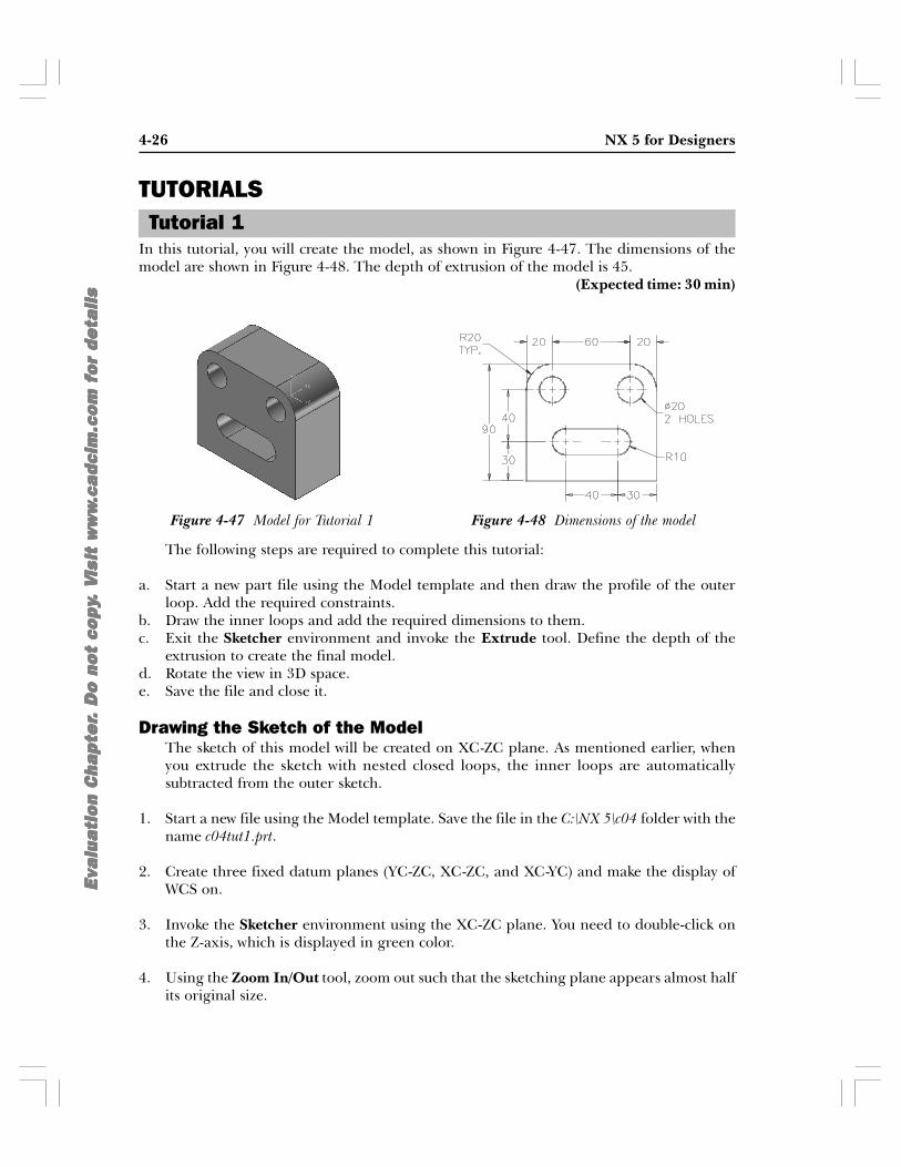
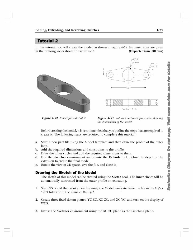
In this tutorial, you will create the model, as shown in Figure 4-47. The dimensions of themodel are shown in Figure 4-48. The depth of extrusion of the model is 45.
(Expected time: 30 min)
The following steps are required to complete this tutorial:
a. Start a new part file using the Model template and then draw the profile of the outerloop. Add the required constraints.
b. Draw the inner loops and add the required dimensions to them.c. Exit the Sketcher environment and invoke the Extrude tool. Define the depth of the
extrusion to create the final model.d. Rotate the view in 3D space.e. Save the file and close it.
Drawing the Sketch of the ModelThe sketch of this model will be created on XC-ZC plane. As mentioned earlier, whenyou extrude the sketch with nested closed loops, the inner loops are automaticallysubtracted from the outer sketch.
1. Start a new file using the Model template. Save the file in the C:\NX 5\c04 folder with thename c04tut1.prt.
2. Create three fixed datum planes (YC-ZC, XC-ZC, and XC-YC) and make the display ofWCS on.
3. Invoke the Sketcher environment using the XC-ZC plane. You need to double-click onthe Z-axis, which is displayed in green color.
4. Using the Zoom In/Out tool, zoom out such that the sketching plane appears almost halfits original size.
Tutorial 1
Figure 4-48 Dimensions of the modelFigure 4-47 Model for Tutorial 1

Editing, Extruding, and Revolving Sketches 4-27
Eva
lua
tio
n C
hap
ter
Eva
lua
tio
n C
hap
ter
Eva
lua
tio
n C
hap
ter
Eva
lua
tio
n C
hap
ter
Eva
lua
tio
n C
hap
ter .
Do
no
t co
py
. D
o n
ot
cop
y.
Do
no
t co
py
. D
o n
ot
cop
y.
Do
no
t co
py .
V. V
. V
. V
. V i
sit
ww
wis
it w
ww
isit
ww
wis
it w
ww
isit
ww
w.c
adc
im.c
om
fo
r de
tail
s.c
adc
im.c
om
fo
r de
tail
s.c
adc
im.c
om
fo
r de
tail
s.c
adc
im.c
om
fo
r de
tail
s.c
adc
im.c
om
fo
r de
tail
s
5. Draw the sketch of the outer loop and add the required geometric and dimensionalconstraints to it, as shown in Figure 4-49.
6. Draw the inner loops and then add the required geometric and dimensional constraints tothem, as shown in Figure 4-50.
Converting the Sketch into the Base FeatureNext, you need to convert the sketch into the base feature. This is done using theExtrude tool.
1. Choose the Finish Sketch button to exit the Sketcher environment; the current view isautomatically changed to the Trimetric view.
2. Right-click and choose Fit from the shortcut menu to make sure that the sketch fits in thescreen.
3. Invoke the Extrude tool from the Feature toolbar; the Extrude dialog box isdisplayed and you are prompted to select the planar face to sketch or selectthe section geometry.
4. Select the sketch; the preview of the extruded feature is displayed and the End edit boxis displayed on the feature.
5. Enter 45 as the value in the End edit box and press the ENTER key; the preview ismodified accordingly.
6. Choose the OK button in the Extrude dialog box; the extrude feature is created anddisplayed in the drawing window.
Figure 4-49 Dimensioned sketch of the outer loop

4-28 NX 5 for Designers
Eva
lua
tio
n C
hap
ter
Eva
lua
tio
n C
hap
ter
Eva
lua
tio
n C
hap
ter
Eva
lua
tio
n C
hap
ter
Eva
lua
tio
n C
hap
ter .
Do
no
t co
py
. D
o n
ot
cop
y.
Do
no
t co
py
. D
o n
ot
cop
y.
Do
no
t co
py .
V. V
. V
. V
. V i
sit
ww
wis
it w
ww
isit
ww
wis
it w
ww
isit
ww
w.c
adc
im.c
om
fo
r de
tail
s.c
adc
im.c
om
fo
r de
tail
s.c
adc
im.c
om
fo
r de
tail
s.c
adc
im.c
om
fo
r de
tail
s.c
adc
im.c
om
fo
r de
tail
s
7. Using the CTRL+B keys, hide the display of the datum axes, datum plane, and thesketch. The extruded model is shown in Figure 4-51.
Rotating the View of the ModelNext, you need to rotate the view of the model so that you can maneuver around it andview it from different directions.
1. Choose the Rotate button from the View toolbar to invoke this tool; the cursor changesto the rotate view cursor.
2. Press and hold the left mouse button and drag the cursor in the drawing window torotate the view of the model.
3. Invoke the Rotate tool again to finish rotating the model.
4. Choose the Isometric button in the View toolbar to restore the Isometric view. If this isnot the default button, then choose the down arrow on the right of the default buttonand choose the Isometric button from the flyout.
5. Right-click in the drawing window and choose Fit from the shortcut menu; the model fitsin the drawing window.
Saving and Closing the File1. Choose File > Close > Save and Close from the menu bar to save and close the file.
Figure 4-51 Extruded model for Tutorial 1
Editing, Extruding, and Revolving Sketches 4-29
Eva
lua
tio
n C
hap
ter
Eva
lua
tio
n C
hap
ter
Eva
lua
tio
n C
hap
ter
Eva
lua
tio
n C
hap
ter
Eva
lua
tio
n C
hap
ter .
Do
no
t co
py
. D
o n
ot
cop
y.
Do
no
t co
py
. D
o n
ot
cop
y.
Do
no
t co
py .
V. V
. V
. V
. V i
sit
ww
wis
it w
ww
isit
ww
wis
it w
ww
isit
ww
w.c
adc
im.c
om
fo
r de
tail
s.c
adc
im.c
om
fo
r de
tail
s.c
adc
im.c
om
fo
r de
tail
s.c
adc
im.c
om
fo
r de
tail
s.c
adc
im.c
om
fo
r de
tail
s
Figure 4-52 Model for Tutorial 2 Figure 4-53 Top and sectioned front view showingthe dimensions of the model
In this tutorial, you will create the model, as shown in Figure 4-52. Its dimensions are givenin the drawing views shown in Figure 4-53. (Expected time: 30 min)
Before creating the model, it is recommended that you outline the steps that are required tocreate it. The following steps are required to complete this tutorial:
a. Start a new part file using the Model template and then draw the profile of the outerloop.
b. Add the required dimensions and constraints to the profile.c. Draw the inner circles and add the required dimensions to them.d. Exit the Sketcher environment and invoke the Extrude tool. Define the depth of the
extrusion to create the final model.e. Rotate the view in 3D space, save the file, and close it.
Drawing the Sketch of the ModelThe sketch of this model can be created using the Sketch tool. The inner circles will beautomatically subtracted from the outer profile on extruding.
1. Start NX 5 and then start a new file using the Model template. Save the file in the C:\NX5\c04 folder with the name c04tut2.prt.
2. Create three fixed datum planes (YC-ZC, XC-ZC, and XC-YC) and turn on the display ofWCS.
3. Invoke the Sketcher environment using the XC-YC plane as the sketching plane.
Tutorial 2

4-30 NX 5 for Designers
Eva
lua
tio
n C
hap
ter
Eva
lua
tio
n C
hap
ter
Eva
lua
tio
n C
hap
ter
Eva
lua
tio
n C
hap
ter
Eva
lua
tio
n C
hap
ter .
Do
no
t co
py
. D
o n
ot
cop
y.
Do
no
t co
py
. D
o n
ot
cop
y.
Do
no
t co
py .
V. V
. V
. V
. V i
sit
ww
wis
it w
ww
isit
ww
wis
it w
ww
isit
ww
w.c
adc
im.c
om
fo
r de
tail
s.c
adc
im.c
om
fo
r de
tail
s.c
adc
im.c
om
fo
r de
tail
s.c
adc
im.c
om
fo
r de
tail
s.c
adc
im.c
om
fo
r de
tail
s
4. Invoke the Zoom In/Out tool and zoom out the screen such that the sketching planeappears almost one-third of its original size.
5. Draw the sketch using the Circle by Center and Diameter option of the Circle tool andthe Line tool, as shown in Figure 4-54. Make sure that the Tangent and Point OnCurve constraints are applied between the lines and the circles at all points where thelines intersect the circles. The Tangent constraint is designated by a small circle and thePoint On Curve constraint is designated by a cross, as shown in Figure 4-54.
NoteTo make sure that both the Tangent and the Point on curve constraints are applied, specify theendpoint of the line only when the symbol of the Tangent constraint is displayed on the left of thecursor and the symbol of the Point on curve constraint is displayed on the right of the cursor.
Next, you need to trim the unwanted portion of the circles to retain the outer profile ofthe model. The sketch is trimmed using the Quick Trim tool.
6. Choose the Quick Trim button from the Sketch Curve toolbar; you are promptedto select the curve to be trimmed.
7. Press and hold the left mouse button inside the right circle and drag it horizontally to theleft, close to the center of the left circle.
8. Release the left mouse button to trim the unwanted portions of the circles, refer toFigure 4-55.
Figure 4-54 Initial sketch for the base feature
Figure 4-55 Sketch after trimming the unwanted portion of circles
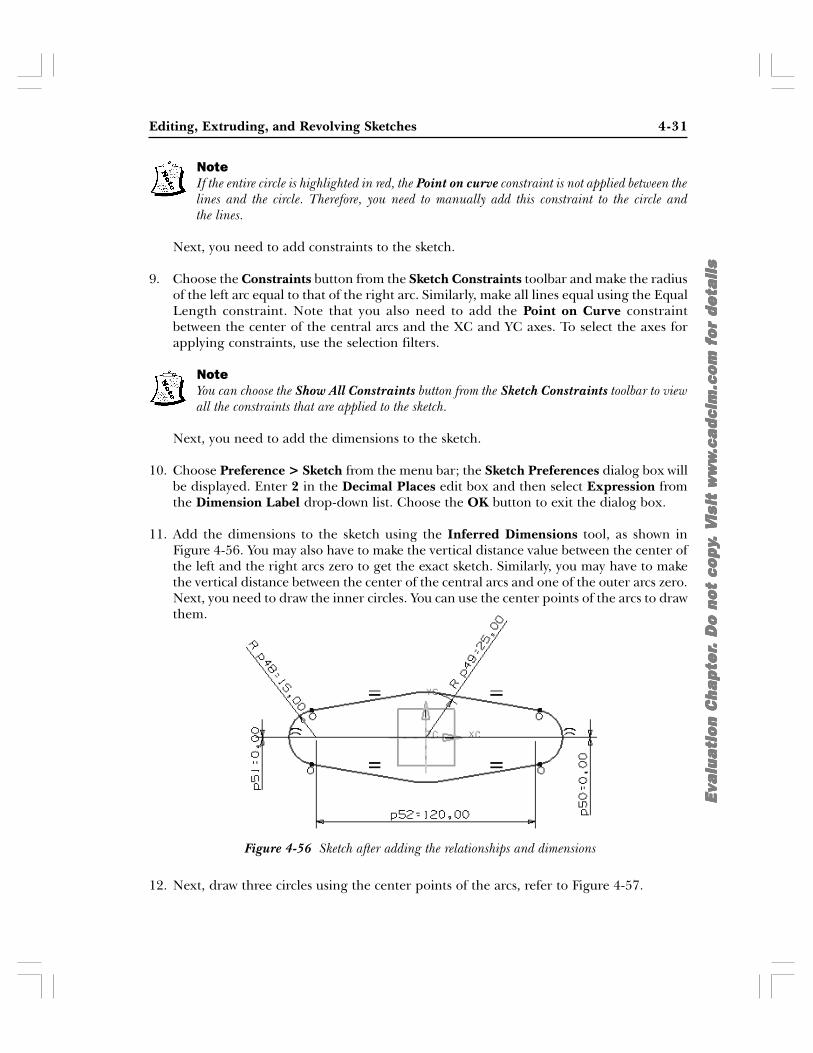
Editing, Extruding, and Revolving Sketches 4-31
Eva
lua
tio
n C
hap
ter
Eva
lua
tio
n C
hap
ter
Eva
lua
tio
n C
hap
ter
Eva
lua
tio
n C
hap
ter
Eva
lua
tio
n C
hap
ter .
Do
no
t co
py
. D
o n
ot
cop
y.
Do
no
t co
py
. D
o n
ot
cop
y.
Do
no
t co
py .
V. V
. V
. V
. V i
sit
ww
wis
it w
ww
isit
ww
wis
it w
ww
isit
ww
w.c
adc
im.c
om
fo
r de
tail
s.c
adc
im.c
om
fo
r de
tail
s.c
adc
im.c
om
fo
r de
tail
s.c
adc
im.c
om
fo
r de
tail
s.c
adc
im.c
om
fo
r de
tail
s
Figure 4-56 Sketch after adding the relationships and dimensions
NoteIf the entire circle is highlighted in red, the Point on curve constraint is not applied between thelines and the circle. Therefore, you need to manually add this constraint to the circle andthe lines.
Next, you need to add constraints to the sketch.
9. Choose the Constraints button from the Sketch Constraints toolbar and make the radiusof the left arc equal to that of the right arc. Similarly, make all lines equal using the EqualLength constraint. Note that you also need to add the Point on Curve constraintbetween the center of the central arcs and the XC and YC axes. To select the axes forapplying constraints, use the selection filters.
NoteYou can choose the Show All Constraints button from the Sketch Constraints toolbar to viewall the constraints that are applied to the sketch.
Next, you need to add the dimensions to the sketch.
10. Choose Preference > Sketch from the menu bar; the Sketch Preferences dialog box willbe displayed. Enter 2 in the Decimal Places edit box and then select Expression fromthe Dimension Label drop-down list. Choose the OK button to exit the dialog box.
11. Add the dimensions to the sketch using the Inferred Dimensions tool, as shown inFigure 4-56. You may also have to make the vertical distance value between the center ofthe left and the right arcs zero to get the exact sketch. Similarly, you may have to makethe vertical distance between the center of the central arcs and one of the outer arcs zero.Next, you need to draw the inner circles. You can use the center points of the arcs to drawthem.
12. Next, draw three circles using the center points of the arcs, refer to Figure 4-57.

4-32 NX 5 for Designers
Eva
lua
tio
n C
hap
ter
Eva
lua
tio
n C
hap
ter
Eva
lua
tio
n C
hap
ter
Eva
lua
tio
n C
hap
ter
Eva
lua
tio
n C
hap
ter .
Do
no
t co
py
. D
o n
ot
cop
y.
Do
no
t co
py
. D
o n
ot
cop
y.
Do
no
t co
py .
V. V
. V
. V
. V i
sit
ww
wis
it w
ww
isit
ww
wis
it w
ww
isit
ww
w.c
adc
im.c
om
fo
r de
tail
s.c
adc
im.c
om
fo
r de
tail
s.c
adc
im.c
om
fo
r de
tail
s.c
adc
im.c
om
fo
r de
tail
s.c
adc
im.c
om
fo
r de
tail
s
13. Add the Equal Radius constraint to the left and right circles. Now, add the requireddimensions to the circles to complete the sketch. The final sketch of the model is shownin Figure 4-57.
Converting the Sketch into the Base FeatureNext, you need to convert the sketch into the base feature. This is done using theExtrude tool.
1. Choose the Finish Sketch button from the Sketcher toolbar to exit the Sketcherenvironment; the current view is automatically changed to the Trimetric view.
2. Invoke the Extrude tool from the Feature toolbar; the Extrude dialog box isdisplayed and you are prompted to select the planar face to sketch or select thesection geometry to extrude.
3. Select the sketch; the preview of the extruded feature is displayed and the End edit boxis displayed on the feature.
4. Enter 20 as the value in the End edit box and press the ENTER key; the preview ismodified accordingly.
5. Choose the OK button in the Extrudedialog box; the extruded feature is createdand displayed in the drawing window, asshown in Figure 4-58.
Notice that the datum plane, sketch, anddatum axes are still displayed in the sketch.For a better visualization of the model, turnoff the display of these entities.
6. Press the CTRL+B keys; the Class Selectiondialog box is displayed. Select all theunwanted entities and then choose OK.
Figure 4-57 Final sketch for Tutorial 2
Figure 4-58 Model after extruding the sketch

Editing, Extruding, and Revolving Sketches 4-33
Eva
lua
tio
n C
hap
ter
Eva
lua
tio
n C
hap
ter
Eva
lua
tio
n C
hap
ter
Eva
lua
tio
n C
hap
ter
Eva
lua
tio
n C
hap
ter .
Do
no
t co
py
. D
o n
ot
cop
y.
Do
no
t co
py
. D
o n
ot
cop
y.
Do
no
t co
py .
V. V
. V
. V
. V i
sit
ww
wis
it w
ww
isit
ww
wis
it w
ww
isit
ww
w.c
adc
im.c
om
fo
r de
tail
s.c
adc
im.c
om
fo
r de
tail
s.c
adc
im.c
om
fo
r de
tail
s.c
adc
im.c
om
fo
r de
tail
s.c
adc
im.c
om
fo
r de
tail
s
Rotating the View of the ModelNext, you need to rotate the model to maneuver and view it from different directions.
1. Choose the Rotate button from the View toolbar to invoke this tool; the cursorchanges to the rotate view cursor.
2. Press and hold the left mouse button and drag the cursor in the drawing window. Figure4-59 shows a model being rotated using the Rotate tool.
3. Choose the Rotate button again to finish rotating the model.
Next, you need to restore the Isometric view of the model, which has been changed bythe Rotate tool.
4. Choose the Isometric button in the View toolbar to restore the Isometric view. If this isnot the default button, then choose the down arrow on the right of the default buttonand choose the Isometric button from the flyout.
5. Now, right-click in the drawing window and choose Fit from the shortcut menu; themodel fits in the drawing window.
Saving and Closing the File1. Choose File > Close > Save and Close from the menu bar to save and close the file.
In this tutorial, you will create the model, as shown in Figure 4-60. This is a revolved bodycreated using the sketch shown in Figure 4-61. (Expected time: 30 min)
The following steps are required to complete this tutorial:
a. Start a new part file using the Model template and draw the sketch of the revolved model.Add the required geometric and dimensional constraints.
b. Exit the Sketcher environment and invoke the Revolved Body tool. Select the sketch tobe revolved and then the direction of the axis of revolution.
Figure 4-59 Rotating the model in 3D space
Tutorial 3

4-34 NX 5 for Designers
Eva
lua
tio
n C
hap
ter
Eva
lua
tio
n C
hap
ter
Eva
lua
tio
n C
hap
ter
Eva
lua
tio
n C
hap
ter
Eva
lua
tio
n C
hap
ter .
Do
no
t co
py
. D
o n
ot
cop
y.
Do
no
t co
py
. D
o n
ot
cop
y.
Do
no
t co
py .
V. V
. V
. V
. V i
sit
ww
wis
it w
ww
isit
ww
wis
it w
ww
isit
ww
w.c
adc
im.c
om
fo
r de
tail
s.c
adc
im.c
om
fo
r de
tail
s.c
adc
im.c
om
fo
r de
tail
s.c
adc
im.c
om
fo
r de
tail
s.c
adc
im.c
om
fo
r de
tail
s
c. Define the other revolution parameters to create the final model.d. Rotate the view in 3D space.e. Save and close the file.
Drawing the Sketch of the ModelThe sketch of the revolved model will be created on the YC-ZC plane.
1. Start a new file using the Model template. Save the file in the C:\NX 5\c04 folder with thename c04tut3.prt.
2. Create three fixed datum planes (YC-ZC, XC-ZC, and XC-YC) and make the display ofWCS on.
3. Invoke the Sketcher environment using the YC-ZC plane.
4. Draw the sketch of the revolved feature and add the required geometric and dimensionalconstraints to it, as shown in Figure 4-62.
Figure 4-61 Dimensions of the model
Figure 4-62 Dimensioned sketch of the revolved feature

Editing, Extruding, and Revolving Sketches 4-35
Eva
lua
tio
n C
hap
ter
Eva
lua
tio
n C
hap
ter
Eva
lua
tio
n C
hap
ter
Eva
lua
tio
n C
hap
ter
Eva
lua
tio
n C
hap
ter .
Do
no
t co
py
. D
o n
ot
cop
y.
Do
no
t co
py
. D
o n
ot
cop
y.
Do
no
t co
py .
V. V
. V
. V
. V i
sit
ww
wis
it w
ww
isit
ww
wis
it w
ww
isit
ww
w.c
adc
im.c
om
fo
r de
tail
s.c
adc
im.c
om
fo
r de
tail
s.c
adc
im.c
om
fo
r de
tail
s.c
adc
im.c
om
fo
r de
tail
s.c
adc
im.c
om
fo
r de
tail
s
Converting the Sketch into the Revolved FeatureNext, you need to convert the sketch into a revolved feature. This is done using theRevolve tool.
1. Choose the Finish Sketch button to exit the Sketcher environment; the current view isautomatically changed to the Trimetric view.
2. Right-click and choose Fit from the shortcut menu to make sure that the sketch fits in thescreen.
3. Invoke the Revolve tool from the Features toolbar; the Revolve dialog box isdisplayed and you are prompted to select the planar face to sketch or selectthe section geometry.
4. Select the sketch drawn and choose the Inferred Vector button from the Axis rollout;you are prompted to select the objects to infer vector.
5. Select the bottom horizontal line as the axis of revolution; the preview of the revolvedbody is displayed.
6. Accept the default options in the Revolve dialog box and choose the OK button; therevolved feature is created.
7. Press the CTRL+B keys to hide the sketch, axes, and the sketching plane. Fit the modelin the screen. The revolved model is shown in Figure 4-63.
Rotating the View of the ModelNext, you need to rotate the model to maneuver and view it from different directions.
1. Choose the Rotate button from the View toolbar to invoke this tool; the cursorchanges to the rotate view cursor.
2. Press and hold the left mouse button and drag the cursor in the drawing window torotate the view of the model. Invoke the Rotate tool again to finish rotating the model.
Figure 4-63 Revolved model of Tutorial 3

4-36 NX 5 for Designers
Eva
lua
tio
n C
hap
ter
Eva
lua
tio
n C
hap
ter
Eva
lua
tio
n C
hap
ter
Eva
lua
tio
n C
hap
ter
Eva
lua
tio
n C
hap
ter .
Do
no
t co
py
. D
o n
ot
cop
y.
Do
no
t co
py
. D
o n
ot
cop
y.
Do
no
t co
py .
V. V
. V
. V
. V i
sit
ww
wis
it w
ww
isit
ww
wis
it w
ww
isit
ww
w.c
adc
im.c
om
fo
r de
tail
s.c
adc
im.c
om
fo
r de
tail
s.c
adc
im.c
om
fo
r de
tail
s.c
adc
im.c
om
fo
r de
tail
s.c
adc
im.c
om
fo
r de
tail
s
3. Choose the Isometric button in the View toolbar to restore the Isometric view. If this isnot the default button, then choose the down arrow on the right of the default button; aflyout is displayed. Now, choose the Isometric button from this flyout.
4. Right-click in the drawing window and choose Fit from the shortcut menu. The modelfits in the drawing window.
Saving and Closing the File1. Choose File > Close > Save and Close from the menu bar to save and close the file.
Answer the following questions and then compare them to those given at the end of thischapter:
1. The Quick Trim tool enables you to remove a portion of the sketch by chopping it off.(T/F)
2. In NX, while extruding a sketch, you can add a draft to it. (T/F)
3. The Quick Extend tool allows you to extend or lengthen an open sketched entity upto the infinity. (T/F)
4. You can set the display modes for the solid models using the buttons in the Standardtoolbar. (T/F)
5. After invoking the Quick Trim tool, you can drag the cursor to trim __________ entities.
6. The __________ option is selected when you need to extrude the sketch symmetrically onboth sides of the plane, on which the sketch is created.
7. The __________ option adds the draft that is aligned with the profile.
8. NX uses the __________ rule to determine the direction of revolution.
9. You can create thin features using the __________ or __________ sketches.
10. You can restore the standard views by choosing various buttons in the __________ toolbar.
Answer the following questions:
1. In NX, which of the following tools enables you to edit sketches?
(a) Edit (b) Modify(c) Transform (d) None
Self-Evaluation Test
Review Questions
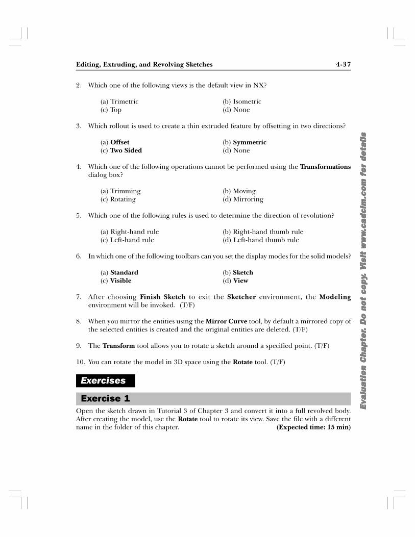
Editing, Extruding, and Revolving Sketches 4-37
Eva
lua
tio
n C
hap
ter
Eva
lua
tio
n C
hap
ter
Eva
lua
tio
n C
hap
ter
Eva
lua
tio
n C
hap
ter
Eva
lua
tio
n C
hap
ter .
Do
no
t co
py
. D
o n
ot
cop
y.
Do
no
t co
py
. D
o n
ot
cop
y.
Do
no
t co
py .
V. V
. V
. V
. V i
sit
ww
wis
it w
ww
isit
ww
wis
it w
ww
isit
ww
w.c
adc
im.c
om
fo
r de
tail
s.c
adc
im.c
om
fo
r de
tail
s.c
adc
im.c
om
fo
r de
tail
s.c
adc
im.c
om
fo
r de
tail
s.c
adc
im.c
om
fo
r de
tail
s
2. Which one of the following views is the default view in NX?
(a) Trimetric (b) Isometric(c) Top (d) None
3. Which rollout is used to create a thin extruded feature by offsetting in two directions?
(a) Offset (b) Symmetric(c) Two Sided (d) None
4. Which one of the following operations cannot be performed using the Transformationsdialog box?
(a) Trimming (b) Moving(c) Rotating (d) Mirroring
5. Which one of the following rules is used to determine the direction of revolution?
(a) Right-hand rule (b) Right-hand thumb rule(c) Left-hand rule (d) Left-hand thumb rule
6. In which one of the following toolbars can you set the display modes for the solid models?
(a) Standard (b) Sketch(c) Visible (d) View
7. After choosing Finish Sketch to exit the Sketcher environment, the Modelingenvironment will be invoked. (T/F)
8. When you mirror the entities using the Mirror Curve tool, by default a mirrored copy ofthe selected entities is created and the original entities are deleted. (T/F)
9. The Transform tool allows you to rotate a sketch around a specified point. (T/F)
10. You can rotate the model in 3D space using the Rotate tool. (T/F)
Open the sketch drawn in Tutorial 3 of Chapter 3 and convert it into a full revolved body.After creating the model, use the Rotate tool to rotate its view. Save the file with a differentname in the folder of this chapter. (Expected time: 15 min)
Exercises
Exercise 1
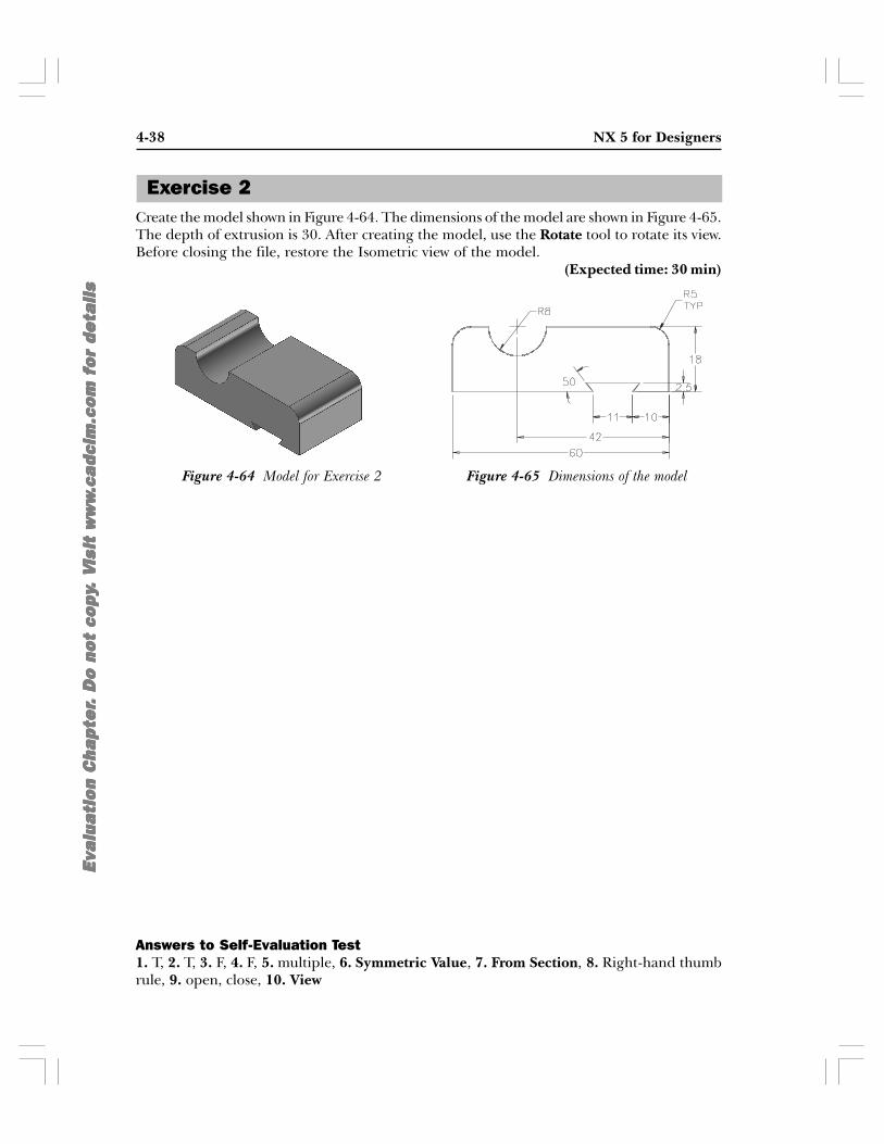
4-38 NX 5 for Designers
Eva
lua
tio
n C
hap
ter
Eva
lua
tio
n C
hap
ter
Eva
lua
tio
n C
hap
ter
Eva
lua
tio
n C
hap
ter
Eva
lua
tio
n C
hap
ter .
Do
no
t co
py
. D
o n
ot
cop
y.
Do
no
t co
py
. D
o n
ot
cop
y.
Do
no
t co
py .
V. V
. V
. V
. V i
sit
ww
wis
it w
ww
isit
ww
wis
it w
ww
isit
ww
w.c
adc
im.c
om
fo
r de
tail
s.c
adc
im.c
om
fo
r de
tail
s.c
adc
im.c
om
fo
r de
tail
s.c
adc
im.c
om
fo
r de
tail
s.c
adc
im.c
om
fo
r de
tail
s
Exercise 2
Figure 4-65 Dimensions of the modelFigure 4-64 Model for Exercise 2
Create the model shown in Figure 4-64. The dimensions of the model are shown in Figure 4-65.The depth of extrusion is 30. After creating the model, use the Rotate tool to rotate its view.Before closing the file, restore the Isometric view of the model.
(Expected time: 30 min)
Answers to Self-Evaluation Test1. T, 2. T, 3. F, 4. F, 5. multiple, 6. Symmetric Value, 7. From Section, 8. Right-hand thumbrule, 9. open, close, 10. View