solvent free synthesis of dibenzyl sulfide using h s …
TRANSCRIPT

SOLVENT FREE SYNTHESIS OF DIBENZYL SULFIDE USING
H2S-RICH MONOETHANOLAMINE AND SOLUBLE PTC
A THESIS SUBMITTED IN PARTIAL FULFILLMENT OF THE REQUIREMENTS FOR
THE DEGREE OF
BACHELOR OF TECHNOLOGY
IN
CHEMICAL ENGINEERING
BY
PARTHA PRATIM PANDA (108CH019)
Under the guidance of
Dr. SUJIT SEN
Department of Chemical Engineering
National Institute of Technology Rourkela
2012

i
National Institute of Technology
Rourkela
CERTIFICATE
This is to certify that the seminar report titled “Solvent free synthesis of Dibenzyl Sulfide
using H2S rich Monoethanolamine under two phase transfer catalysis” submitted by Partha
Pratim Panda bearing Roll no. 108CH019 in partial fulfillment of the requirements for the
prescribed curriculum of Bachelor of Technology in Chemical Engineering Session 2008-
2012 in the Department of Chemical Engineering, National Institute of Technology, Rourkela
is an authentic work to the best of my knowledge and belief.
Date: Dr. Sujit Sen
Dept. of Chemical Engineering
National Institute of Technology
Rourkela-769008

ii
ACKNOWLEDGEMENT
A lot of people have been involved in the making of this project to whom I would like to
thank from the bottom of my heart. Though it is not possible to acknowledge each and every
one, some people deserve a special mention.
First and foremost, I would like to thank my project guide, Prof. Sujit Sen who has been a
guide and mentor. He has been instrumental in pushing me to my limits and providing me
with research material from various sources.
My parents and friends have been patient all this while and my sincere thanks to all of them.
Last but not the least, I offer my gratitude to the least acknowledged “Internet” without which
this report would not have seen the light of the day.
Date: Partha Pratim Panda
108CH019
Dept. of Chemical Engineering
NIT Rourkela
iii
ABSTRACT
With the depletion of crude oil reserves, oil refineries are being forced to process sour crude
which is high in sulfur content. Sulfur, if not removed from the system may corrode the
system or may lead to unwanted side reactions which would entail consumption of reactants
and energy. Usually the sulfur is removed by absorption in ammonia solution which is further
processed in a Claus Unit to produce elemental sulfur which requires a high amount of
energy. Also, the supply of elemental sulfur usually outstrips demand thereby eroding the
profit margins. With a view to making more sophisticated fine chemicals which have higher
usability and better market value, this project was undertaken to study the kinetics of the
solvent-free synthesis of dibenzyl sulfide was carried out using H2S-rich monoethanolamine
under two phase transfer catalysis with a phase transfer catalyst (PTC), polyethylene glycol
(PEG). The effects of different parameters, such as speed of agitation, temperature,
monoethanolamine concentration, catalyst concentration, initial sulfide concentration and
concentration of benzyl chloride, on the conversion and reaction rate of benzyl chloride were
studied to establish the mechanism of the reaction.

iv
CONTENTS
Certificate i
Acknowledgement ii
Abstract iii
Contents iv
List of Figures vi
List of Tables vii
Nomenclature vii
Chapter 1 Introduction 1-15
1.1 Sources of Hydrogen Sulfide 2
1.2 Need for treating H2S laden gas 2
1.3 Industrial Processes for removal and recovery of H2S 3
1.3.1 Ammonia-based process 4
1.3.2 Alkanolamine-based process 6
1.4 Sulfur recovery from H2S 7
1.4.1 The Claus Process 7
1.4.2 Crystasulf Process 10
1.4.3 LO-CAT Process 10
1.5 Present Work 10
1.6 Phase Transfer Catalysis 11
1.7 Polyethylene Glycol (PEG) 14
1.8 Reactions 15
Chapter 2 Literature Survey 16-18
Chapter 3 Experimental Setup 19-24
3.1 Chemicals 20

v
3.2 Equipment 20
3.3 Preparation of H2S rich monoethanolamine 21
3.4 Experimental Procedure 22
3.5 Analysis 22
3.5.1 Analysis of the organic phase 22
3.6 Determination of sulfide concentration 22
Chapter 4 Results and Discussion 25-31
4.1 Introduction 26
4.2 Parametric Study 26
4.2.1 Effect of stirring speed 27
4.2.2 Effect of catalyst concentration 28
4.2.3 Effect of initial sulfide concentration 29
Chapter 5 Conclusion 32-33
References 34-37

vi
LIST OF FIGURES
Sl. No. Figure Page
1 Schematic flow diagram of the amine gas treating process 7
2 Schematic flow diagram of the Claus process 9
3 Schematic representation of extraction mechanism 12
4 Structure of Polyethylene Glycol (PEG) 14
5 Batch reactor assembly 21
6 Kipp’s Apparatus 24
7 Overall reaction 26
8 Effect of stirring speed on BC conversion 27
9 (a) Effect of catalyst concentration on BC conversion 28
9 (b) Effect of catalyst concentration on DBS selectivity 29
10 (a) Effect of initial sulfide concentration on BC conversion 30
10 (b) Effect of initial sulfide concentration on DBS selectivity 31

vii
LIST OF TABLES
Sl. No. Table Page
1 Exposure Limits: US Department of Labour 2
2 Commonly used phase transfer catalysts 13

viii
NOMENCLATURE
MEA- Mono Ethanol Amine
PTC- Phase Transfer Catalyst
PEG- Polyethylene Glycol
DBS- Dibenzyl sulfide
BM- Benzyl Mercaptan
BC- Benzyl Chloride

1
Chapter 1
Introduction

2
1. INTRODUCTION
1.1 Sources of Hydrogen Sulfide
Human activity accounts for about 10% of global H2S emissions and this is rising at a steady
pace. By far the largest contributor to these emissions is the petroleum industry which
accounts for almost 80% of total emissions. Natural gas can contain up to 90% hydrogen
sulfide. The hydrodesulfurization process is used to remove sulfur with the help of hydrogen
gas in which large quantities of hydrogen sulfide and ammonia are produced. With the
gradual decline of light and easy-to-process crude oils, refineries throughout the world are
forced to process heavy crudes containing high amount of sulfur and nitrogen. In addition,
refineries have to hydrotreat such crudes to bring down the sulfur levels to those prescribed
by environmental protection agencies. During hydrotreatment of heavy and sour crude, large
quantities of ammonium sulfide and ammonia are produced. Though coal gas contains very
low amounts of hydrogen sulfide, the absolute quantities become significant in the wake of
increase in coal gas production. Other man-made are tanneries, coke ovens and paper mills.
1.2 Need for treating H2S laden gas
With increased environmental activism and sensitization, refineries all over the world are
looking at decreasing their hydrogen sulfide emissions.
Table 1. Exposure Limits: US Department of Labour
Occupational Health and Safety Administration (OSHA) Permissible Exposure
Limit (PEL) for general industry
10 ppm
American Conference of Governmental Industrial Hygienists (ACGIH)
Threshold Limit Value (TLV)
10 ppm

3
National Institute of Occupational Safety and Health (NIOSH) Recommended
Exposure Limit (REL)
10 ppm
NIOSH Immediately Dangerous to Life or Health Concentration (IDLH) 100 ppm
Some of the compelling reasons for reducing the presence of hydrogen sulfide are:
Hydrogen Sulfide is a toxic and highly flammable gas and being heavier than air, it
tends to accumulate at the bottom of poorly ventilated spaces. Although very pungent
at first, it quickly nullifies the smelling capability, thus afflicted victims may be
unaware of its presence until its concentration becomes fatal. For safety issues related
to handling, an appropriate material safety data sheet (MSDS) should be consulted.
The prescribed standards by different American agencies are given in Table 1.
H2S is odiferous in nature, corrosive in the presence of water and poisonous in very
small concentrations. Therefore, it must almost completely be removed from the gas
streams before use and preferably before transport.
The presence of H2S in the refinery gas streams can cause a number of detrimental
problems in subsequent processing steps such as corrosion of process equipment,
deterioration and deactivation of the catalysts, undesired side reactions, increase in the
process pressure requirements, and increase in the gas compressor capacity, etc.
The supply of elemental sulfur highly outstrips the demand, therefore the price of
sulfur is very low in the market and thus it doesn’t make business sense to produce it
by spending large amounts of men and money.
1.3 Industrial Processes for Removal and Recovery of H2S
A number of industrial processes have been developed to remove hydrogen sulfide and bring
it within acceptable limits to conform to strict environmental regulations. Hydrogen sulfide

4
being weakly acidic, its removal can be effected by the use of an alkaline solution. Since
strong alkaline solutions like potassium hydroxide react irreversibly with hydrogen sulfide, it
is prudent to use a weakly alkaline solution which can be regenerated and used again and
again.
1.3.1 Ammonia-based Process
Use of aqueous ammonia in removal of H2S (sometimes along with NH3) from gas streams
had been well practiced [13] [14]
. Gas streams containing both H2S and NH3 pass through a H2S
scrubber and an NH3 scrubber in series. Stripped water is fed to the top of the NH3 scrubber
where it absorbs NH3 from the gas. The resulting NH3 solution is then used as absorbent for
H2S in the H2S scrubber. The rich solution, from this unit containing ammonium sulfide in
solution, is fed to a deacidifier, which decomposes the ammonium sulfide to produce H2S
rich vapor and NH3 rich liquor. The use of ammonia to remove hydrogen sulfide and carbon
dioxide from gas streams has declined in recent years; however, the process is still used to
desulfurize coke-oven gas in a number of installations.
There are a few notable advantages with the NH3-based process over amine-based process
[15]:
The NH3-based process is suitable for gas streams containing both H2S and NH3, as
simultaneous removal of NH3 is obvious in this process. Moreover, for the gas
streams containing both H2S and NH3, the removal of both impurities could be done
in a single step in the ammonia-based process instead of two steps as in the case of
alkanolamine-based process (NH3 removal by water scrubbing followed by H2S
removal through the amine treating unit).
5
The rate of absorption of H2S into aqueous NH3 solution is rapid and dependent upon
the concentration of NH3. Therefore, with adequate NH3 concentration at the
interface, it is possible that the gas film resistance governs the rate of absorption of
H2S. On the other hand, absorption of CO in weak alkaline solution like aqueous NH3
is considered typical of a liquid film controlled system. The result is that when gases
containing both H2S and CO2 are contacted with aqueous NH3 solution, the H2S is
absorbed much more rapidly than the CO2. Yet another aspect is that once in solution,
the CO2 is stronger acid than H2S and under equilibrium conditions, process would
actually be expected to be selective for CO2. Therefore, by using aqueous NH3, the
selective absorption of H2S or CO2 is possible from the gases containing both H2S and
CO2. By the use of spray column in combination with short contact time can lead to
the selective absorption of H2S from the gas mixture containing both CO2 and H2S.
NH3 has the advantage for such applications being essentially unaffected by the
presence of carbonyl sulfide (COS), carbon disulfide (CS2) and hydrogen cyanide
(HCN).
Despite these advantages, the use of ammoniacal scrubbing has not been universally accepted
in the gas treating art as the preferred method for removing H2S from a gas stream. This is
primarily because of a number of operational difficulties associated with its implementation
[13], such as:
High partial pressure of NH3 forces the scrubbing step be conducted with relatively
dilute NH3 solutions or at relatively high pressures or a separate water wash step after
the NH3 scrubbing step in order to remove NH3 from the treated gas stream. In
addition, the use of dilute scrubbing solutions typically increases substantially the

6
regeneration costs where the regeneration step is conducted at a considerably higher
temperature than the scrubbing step.
Another difficulty is associated with the regeneration of the rich absorbent solution
withdrawn from the scrubbing step. Several regeneration procedures have been
proposed but they typically involve the use of soluble catalysts such as hydroquinone
and have had problems such as contamination of the sulfur product with the catalyst,
excessive formation of side products such as ammonium sulfate and thiosulfate and
loss of scrubbing solution and catalyst during the periodic purges that are generally
required to remove side products from the system. Other difficulties have been
associated with the recovery of the elemental sulfur from the regeneration step where
it has been customary to form a froth of sulfur, which then must be skimmed off and
filtered.
1.3.2 Alkanolamine-based process
Although both ammonia and alkanolamine-based processes are in use for the removal of acid
gas constituents (H2S and CO2) from gas streams, alkanolamine-based process got wide
commercial acceptance as the gas treating art because of its advantages of low vapor pressure
(high boiling point) and ease of reclamation. The low vapor pressure of alkanolamines makes
the operation more flexible in terms of operating pressure, temperature, and concentration of
alkanolamine in addition to the negligible vaporization losses.
The basic flow diagram of amine-based acid gas removal process is shown in Figure 1.
Treatment with alkanolamines involves circulating gas stream upward through the absorber,
countercurrent to the stream of aqueous alkanolamine solution. The rich solution from the
bottom of the absorber is heated by heat exchange with lean solution from bottom of the
stripping column and is then fed to the stripping column where the absorbed gases are

7
stripped off from the alkanolamine solution. The regenerated alkanolamine is then recycled to
the absorber. The concentrated hydrogen sulfide off gas obtained from the top of the stripping
column is then subjected to S recovery or disposal.
Figure 1: Schematic flow diagram of the amine gas treating process
1.4 Sulfur recovery from H2S
1.4.1 The Claus Process
The Claus process is the most significant gas desulfurizing process, recovering elemental
sulfur from gaseous hydrogen sulfide. First patented in 1883 by the scientist Carl Friedrich
Claus, the Claus process has become the industry standard.
H2S gas separated from the host gas stream using amine extraction is fed to the Claus unit
(Figure 2), where it is converted in two steps:

8
1. Thermal Step: The H2S-laden gas reacts in a sub-stoichiometric combustion with air.
This is done in a reaction furnace at high temperatures (1000 – 1400oC). Claus gases (acid
gas) with no further combustible contents apart from H2S are burned in burner by the
following chemical reaction:
2 H2S + 2 O2 → SO2 + 2 H2O + S
This is a strongly exothermic free-flame total oxidation of hydrogen sulfide generating
sulfur dioxide that reacts away in subsequent reactions. The air to the acid gas ratio is
controlled such that in total 1/3 of all hydrogen sulfide (H2S) is converted to SO2. This
ensures a stoichiometric reaction for the Claus reaction in the second catalytic step.
2. Catalytic Step: The reaction gases leaving the sulfur condenser are reheated to 200-
350oC and fed to a series of catalytic converters ans sulfur condenser where H2S react
with SO2 to produce elemental sulfur:
2 H2S + SO2 → 3 S + 2 H2O
The catalyst used in the catalytic converter is normally either activated aluminum (III) or
titanium (IV) oxide.
Inevitably a small amount of H2S remains in the tail gas. This residual quantity, together
with other trace sulfur compounds, is usually dealt with in a tail gas unit. The latter can
give overall sulfur recoveries of about 99.8%, which is very impressive indeed. Sulfur is
used for manufacturing sulfuric acid, medicine, cosmetics, fertilizers and rubber products.
Elemental sulfur is used as fertilizer and pesticide.

9
However, the Claus process has a number of inherent disadvantages [16] [17] [18]
. For
example:
It operates at high temperatures.
It requires exact process control over the ratio of oxygen to H2S in the feed.
The valuable hydrogen energy is lost in this process.
It requires expensive pretreatment of the feed gas if CO2 is present in high
concentrations. At least a portion of the CO2 must be removed from the byproduct
gas by pretreatment before oxidizing the H2S to maintain the efficiency of the
oxidation process.
The sulfur content of Claus process tail gas released to the atmosphere is generally
too high to meet stringent environmental regulations. To comply with these
regulations, it is necessary to add more Claus stages and/or employ a separate tail
gas cleanup process at great expense.
Figure 2: Claus Process

10
1.4.2 CrystaSulf Process
CrystaSulf is a chemical process used for removing hydrogen sulfide from natural gas,
synthesis gas and gas streams in refineries and chemical plants. CrystaSulf uses a liquid
phase Claus reaction to convert the hydrogen sulfide (H2S) into elemental sulfur which is
then removed from the process by filtration. This process is used in the energy industry as a
one-step alternative to Amine–Claus process.
1.4.3 Wet-oxidation LO-CAT Process
In the LO-CAT process, hydrogen sulfide is converted to elemental sulfur using an
environmentally safe chelated iron catalyst. The iron catalyst is held in solution by organic
chelating agents that wrap around the iron ions in a claw like fashion, preventing
precipitation of either iron sulfide (FeS) or iron hydroxide (Fe(OH)3). According to this
process, the hydrogen sulfide, absorbed into the slightly alkaline, aqueous LO-CAT solution
(pH 8.0-8.5), is oxidized to elemental sulfur by reducing the iron ions from the ferric to the
ferrous state. The reduced iron ions are then transferred from the absorber to the oxidizer
where the ferrous iron is re-oxidized to ferric iron by atmospheric oxygen, absorbed into the
LO-CAT solution, thus regenerating the catalyst.
1.5 Present Work
The present work was undertaken to develop an alternative process (alternative to Claus or
LO-CAT process) for better utilization of H2S present in various gas streams. The present
work deals with the production of value-added chemicals utilizing the H2S present in various
byproduct gas streams obtained from different chemical industries. In accordance with the
present process, value-added chemicals were produced from the H2S-rich aqueous ammonia
or alkanolamine that could be obtained from scrubbing step of the corresponding ammonia-

11
or alkanolamine-based process. In other words, the removal of H2S was assumed to be done
by conventional process. The present investigations are devoted to:
Synthesis of value-added fine chemicals like dibenzyl sulfide, benzyl mercaptan, and
aryl amines using the H2S-rich aqueous ammonia and/or alkanolamines under two
phase (liquid-liquid) conditions in the presence of a phase transfer catalyst (PTC),
polyethylene glycol (PEG).
Study the influence of process variables (stirring speed, catalyst loading,
concentration of reactant, and temperature, alkanolamine concentration, elemental
sulfur loading) on the conversions organic reactants and selectivity of various
products.
Establish a suitable mechanism or stoichiometry utilizing the effects of various
parameters on the reaction rate and conversion, to explain the course of the reaction.
Kinetic modeling of the above mentioned commercially important reactions and
estimation of the model parameters.
1.6 Phase Transfer Catalysis
Phase transfer catalysts (PTC) are widely used to intensify otherwise slow heterogeneous
reactions involving an organic substrate and an ionic reactant, either dissolved in water
(liquid-liquid) or present in solid state (solid-liquid).
Phase transfer catalysis is now an attractive technique for organic synthesis because of its
advantages such as
Simplicity of process
Reduced consumption of organic solvent and raw materials
Mild operating conditions
Enhanced reaction rates

12
Better selectivity
Among several varieties of PTCs, quaternary ammonium salts have been reported to be the
most active PTC among different catalysts used. But the usage of Poly-Ethylene Glycol
(PEG) for the synthesis of Dibenzyl Sulfide has not been reported in literature. Present study
was therefore carried out using PEG as PTC.
Two mechanisms, interfacial and extraction, are generally used to explain the liquid-liquid
phase transfer catalysis based on the lipophilicity of the quaternary cation. The extraction
mechanism (Figure 3) is applicable to catalysts that are not highly lipophilic or that can
distribute themselves between the organic and the aqueous phase, such as
benzyltriethylammonium, dodecyltrimethylammonium, and tetrabutylammonium salts [19] [20]
.
In the interfacial model, catalysts such as tetrahexylammonium and trioctylmethylammonium
salts remain entirely in the organic phase because of their high lipophilicity, and exchange
anions across the liquid-liquid interface [21]
.
Figure 3: Schematic representation of extraction mechanism

13
Table 2. Commonly used PTCs[12]
Catalyst Cost Stability and Activity Use and Recovery of
Catalyst
Ammonium Salts Cheap Moderately stable under
basic conditions and up to
100oC. Moderately active
Widely used.
Recovery is
relatively difficult.
Phosphonium Salts Costlier than
ammonium salts
More stable thermally than
ammonium salts, although
less stable under basic
conditions.
Widely used.
Recovery is
relatively difficult.
Crown ethers Expensive Stable and highly active
catalysts both under basic
conditions and at higher
temperatures up to even
150-2OO oC
Often used. Recovery
is difficult and poses
environmental issues
due to their toxicity.
Cryptands Expensive Stable and highly reactive,
except in the presence of
strong acids.
Used sometimes
despite high costs
and toxicity, due to
higher reactivity.
PEG Very cheap More stable than quaternary
ammonium salts, but lower
activity.
Often used. Can be
used when larger
quantities of catalyst
cause no problems.
Relatively easy to
recover.
1.7 Polyethylene Glycol (PEG)
Environment has become the buzzword in the past decade and no field of science has
remained untouched. These days the focus has shifted to not only increase the productivity
but also doing it in such a way so as to have minimum adverse impact on the environment.
Organic reactions without the use of harmful organic solvents are now of great interest in
organic synthesis. Attempts have been made to develop solvent-free chemistry, which to
some extent have been successful in a few transformations. PTCs like TBAB are very
difficult to recover and reuse and are harmful to the environment. With that concern in view,

14
the focus has been the use of environment friendly catalysts such as polyethylene glycol. [11]
PEG and its monomethyl ethers are inexpensive, thermally stable, recoverable, and nontoxic
media for phase-transfer catalysts. PEG, a biologically acceptable polymer used extensively
in drug delivery and in bioconjugates as tool for diagnostics, has thus far not been widely
used as a PTC but has been used as a support for various transformations. [11]
Figure 4: Structure of Polyethylene Glycol (PEG)

15
1.8 Reactions
Generation of H2S:
FeS + H2SO4 - H2S + FeSO4 + H2O
H2S absorption in MEA:
H2SHS- + H
+
HO-CH2-CH2-NH2 + H2S HO-CH2-CH2-NH3+
+ HS-
HO-CH2-CH2-NH2 + HS- HO-CH2-CH2-NH3
+ + S
2-
Reactions:
PhCH2Cl + RNH3HS PhCH2SH + RNH3+Cl
-
PhCH2Cl + PhCH2SH PhCH2SCH2Ph + HCl

16
Chapter 2
Literature Survey

17
2. LITERATURE SURVEY
Maity et al. (2006) have synthesized toluidine by the reduction of nitrotoluenes using aqueous
ammonium sulfide under liquid–liquid phase transfer catalysis in the presence of TBAB as
catalyst. They also studied the kinetics of reduction of nitrotoluenes by H2S rich
ethanolamine using TBAB and also carried out reduction of o-nitroanisole to o-anisidine
byH2S-rich aqueous diethanolamine.
Yadav and Badure (2007) studied the role of third phase in the intensification of reaction
rates and selectivity in phase transfer catalyzed synthesis of benzyl phenyl ether.
Pradhan and Sharma (1992) studied the solid-liquid reactions of benzyl chloride with Solid
sodium sulfide catalyzed by alumina and ion exchange resin.
Maity et al. (2007) studied the effects of various process parameters on conversion and
selectivity associated with the synthesis of dibenzyl sulfide by the reaction between benzyl
chloride and aqueous ammonium sulfide using TBAB as a phase transfer catalyst.
Sen et al. developed a mechanistic model for the reaction of benzyl chloride with aqueous
ammonium sulfide in the presence of TBAB as a phase transfer catalyst.
It is evident from the above discussion that there is hardly any information in the literature on
the reduction of benzyl chloride by the use of H2S rich MEA and PEG as a phase transfer
catalyst. Considering the importance of the system, a detailed study was therefore performed,
and is reported in the present work, on the reduction of benzyl chloride to produce
commercially important dibenzyl sulfide. The effects of various parameters on the reaction
rate and conversion were studied to establish the mechanism and the stoichiometry of the

18
reaction. A generalized empirical kinetic model applicable for all the benzyl chloride was
also developed to correlate the experimental data.

19
Chapter 3
Experimental Setup

20
3. EXPERIMENTAL SETUP
3.1 Chemicals
Toluene (≥ 99%) was procured from RFCL Limited, New Delhi, India. Monoethanolamine
was procured from Loba Chemie (India) Pvt. Ltd., Mumbai, India. Benzyl Chloride (>99%)
was obtained from Merck (India) Ltd., Mumbai, India. PEG-600 (> 99%) was procured from
ThermoFisher Scientific India Ltd., Mumbai, India. H2SO4 (98%) and NaOH pellets (97%)
were procured from Merck (India) Ltd., Mumbai, India. Na2S2O3 (≥ 99%), KI (≥99.2%) and
KIO3 (≥99.5%) were also obtained from Merck (India) Ltd., Mumbai, India.
3.2 Equipment
All the reactions were carried out in batch mode in a fully baffled mechanically agitated glass
reactor of capacity 250 cm3 (6.5 cm i.d.). A 2.0 cm-diameter six-bladed glass disk turbine
impeller with the provision of speed regulation, located at a height of 1.5 cm from the
bottom, was used for stirring the reaction mixture. The reactor assembly was kept in a
constant temperature water bath whose temperature could be controlled within ±1oC. The
schematic diagram of the experimental setup is as shown in Figure 6.

21
Figure 5. Batch Reactor Assembly
3.3 Preparation of H2S-rich Monoethanolamine
For the preparation of H2S-rich aqueous monoethanolamine (MEA), around 30-35wt%
aqueous alkanolamine solution was prepared first by adding a suitable quantity of desired
alkanolamine in distilled water. Then H2S gas was bubbled through this aqueous ammonium
sulfide or aqueous alkanolamines in two 50 cm3 standard gas bubblers connected in series.
Since the reaction of H2S with ammonium hydroxide and with alkanolamines is exothermic
(Kohl and Nielsen, 1997), the gas bubbler containing aqueous alkanolamine was kept
immersed in an cold water bath in order to prevent the oxidation of sulfide and thus to
prevent the formation of disulfide. The unabsorbed H2S gas from the first bubbler was sent to
another bubbler containing 1M sodium hydroxide solution whose outlet was open to the
atmosphere. The gas bubbling was continued until the bubbling had stopped in both the gas
bubblers.

22
3.4 Experimental Procedure
In a typical experimental run, 50 cm3 of aqueous phase containing a known concentration of
H2S-rich Monoethanolamine was charged into the reactor and kept well agitated until the
steady state temperature was reached. Then 50 cm3 of the organic phase containing measured
amount of organic reactant (benzyl chloride) and catalyst (PEG) kept separately at the
reaction temperature, was charged into the reactor. The reaction mixture was then agitated at
a constant speed of stirring. About 0.5 cm3vof the organic layer was withdrawn at a regular
time interval after stopping the agitation and allowing the phases to separate.
3.5 Analysis
3.5.1 Analysis of organic phase
All samples from the organic phase were analyzed by gas liquid chromatography (GLC)
using a 2 m × 3 mm stainless steel column packed with 10% OV-17 on Chromosorb W
(80/100). A Chemito Model 8610 GC was used for the analysis. An FID detector was used
with nitrogen as the carrier gas during the analysis.
3.6 Determination of Sulfide Concentration
Initial sulfide concentrations were determined by standard iodometric titration method (Scott,
1966) as given below.
Preparation of standard (0.025 M) KIO3 solution
4.28g of KIO3 was weighed accurately and dissolved in distilled water and was made up to 1
L in a graduated volumetric flask.
Preparation of standard (0.1 M) sodium thiosulfate solution

23
25g of Na2S2O3.5H2O crystals was weighed and dissolved in distilled water and made up to 1
litre in a graduated volumetric flask with distilled water.
Standardization of sodium thiosulfate solution by standard potassium iodate solution
25 cm3 of 0.025M KIO3 solution was taken and 1g (excess) of potassium iodide (KI) was
added to it followed by 3 cm3 of 1M sulfuric acid. The liberated iodine (I2) was titrated with
thiosulfate solution. When the color of the solution became a pale yellow, it was diluted to
200 cm3 with distilled water. 2 cm
3 of starch solution was added, and the titration was
continued until the color changed from blue to colorless. The chemical reaction involved in
this titration is given below.
KIO3 + 5KI + 3 H2SO4 = 3I2 + 3H2O + 3K2SO4
2 Na2S2O3 + I2 = Na2S4O6 + 2NaI
Therefore, 1 mole of KIO3 ≡ 3 × 2 mole of Na2S2O3
Estimation of sulfide concentration
Hydrogen sulfide and soluble sulfides can be determined by oxidation with potassium iodate
in an alkaline medium. 15 cm3 of standard (0.025M) potassium iodate solution was taken in a
conical flask. 10 cm3 of sulfide solution containing about 2.5 mg of sulfide was then added to
it followed by the addition 10 cm3
of 10M sodium hydroxide solution. The mixture was
boiled gently for about 10 minutes, cooled, and 5 cm3
of KI solution and 20 cm3 of 4M
sulfuric acid solution were added to it. The liberated iodine was titrated, which was
equivalent to the unused potassium iodate, with a standard 0.1M sodium thiosulfate in the
usual manner. The potassium iodate in the alkaline medium oxidizes the sulfide to sulfate as

24
given by the following reaction. For sulfide solution having sufficiently high sulfide
concentration, suitable dilution was made before the estimation of sulfide by above
mentioned procedure.
4 IO3- + 6 OH
- + 3 S
2- = 3 SO4
2- + 4 I
- + 6H2O
4 mole of IO3- ≡ 3 mole of S
2-
H2S concentration = [15 * Siodate – (Vthiosulfate * Sthiosulfate)/6] *3/4* Nd/10
Where Siodate = Strength of KIO3
Vthiosulfate = Volume of thiosulfate
Sthiosulfate = Strength of thiosulfate
Nd = Number of times of dilution
Figure 6. Kipp’s Apparatus

25
Chapter 4
Results and Discussion

26
RESULTS AND DISCUSSION
4. 1 Introduction
In refining and other petrochemical industries, hydrogen sulfide is usually removed from by
absorption in aqueous alkanolamines. Amines are regenerated in the strippers releasing H2S,
which is further subjected to the Claus process releasing elemental sulfur.
In the present study, the reaction of benzyl chloride (BC) with H2S-rich aqueous
monoethanolamine (MEA) was carried out in batch mode under two-phase conditions
(liquid-liquid) both in the absence and in the presence of phase transfer catalyst (PTC),
namely, Polyethylene Glycol (PEG). Dibenzyl sulfide (DBS) and benzyl mercaptan (BM)
were detected as the products from the reaction mixture by gas liquid chromatography
(GLC). The commercial importance of these compounds has been mentioned in Conclusion.
Although there is a possibility of formation of benzyl alcohol by alkaline hydrolysis of benzyl
chloride and N-benzyl monoethanolamine by substitution of chlorine atom by MEA, neither
of them was detected in the reaction mixture even after a batch time of 6 hours. Accordingly,
the overall reaction may broadly be represented by Figure 8.
Figure 7. Overall Reaction
Parametric studies were performed following one-variable-at-a-time (OVAT) approach to see
the effect of various parameters such as stirring speed, temperature, aqueous sulfide
concentration, MEA concentration, catalyst loading and BC concentration on BC conversion
and DBS selectivity. From the detailed study of the effects of various parameters on the
reaction, a suitable mechanism was established which could explain the course of the
reaction.

27
4.2 Parametric Study
4.2.1 Effect of stirring speed
To evaluate the role of mass transfer resistance in this system, the stirring speed was varied
and corresponding reaction rates were observed and plotted on a graph. The chart shows that
the conversion rate of BC is nearly independent of the stirring speed. Thus we can conclude
that in the present system, mass transfer factors do not affect the conversion rate which is
almost purely controlled by kinetics. Hence, all the other experiments were performed at a
stirring speed of 1500 rpm.
Figure 8. Effect of stirring speed on BC conversion. Volume of organic phase = 5.0×10⁻⁵
m3; volume of aqueous phase = 5.0×10
−5 m
3; concentration of BC= 8.69 kmol/m
3;
concentration of catalyst = 2%; concentration of sulfide = 1.23 kmol/m3; temperature =303K;
0
10
20
30
40
50
60
70
80
90
100
0 60 120 180 240 300 360
% c
on
vers
ion
of
ben
zyl c
hlo
rid
e
Reaction Time (min)
Effect of stirring speed on the conversion of benzyl chloride
1000 RPM
1500 RPM
2000 RPM
Stirring Speed

28
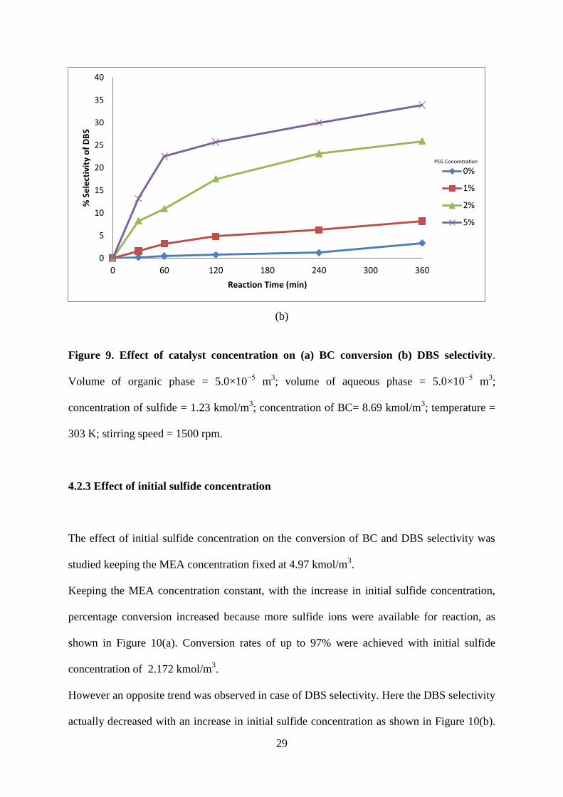
4.2.2 Effect of catalyst concentration
The effect of catalyst (PEG) concentration on BC conversion was studied in the concentration
range of 0 – 5 % of organic phase, as shown in Fig. 9(a). With increase in catalyst
concentration, BC conversion as well as reaction rate increases. Only by increasing the
catalyst concentration, BC conversion of about 96% was achieved whereas it was about 53%
without catalyst even after 360 min of reaction under otherwise identical conditions. Fig. 9(a)
also shows that over 2 % concentration of the catalyst, the conversion of BC becomes
constant.
This can be explained by the fact that the mass transfer of the active species into organic
phase reaches a maximum value. The selectivity of DBS increases with increase in catalyst
concentration as shown in Fig. 9(b). Therefore, the selectivity of BM decreases with increase
in catalyst concentration.
(a)
0
20
40
60
80
100
120
0 60 120 180 240 300 360
% C
on
vers
ion
of
Be
nzy
l Ch
lori
de
Reaction Time (mins)
0%
1%
2%
5%
PEG Concentration
29
(b)
Figure 9. Effect of catalyst concentration on (a) BC conversion (b) DBS selectivity.
Volume of organic phase = 5.0×10⁻⁵
m3; volume of aqueous phase = 5.0×10
−5 m
3;
concentration of sulfide = 1.23 kmol/m3; concentration of BC= 8.69 kmol/m
3; temperature =
303 K; stirring speed = 1500 rpm.
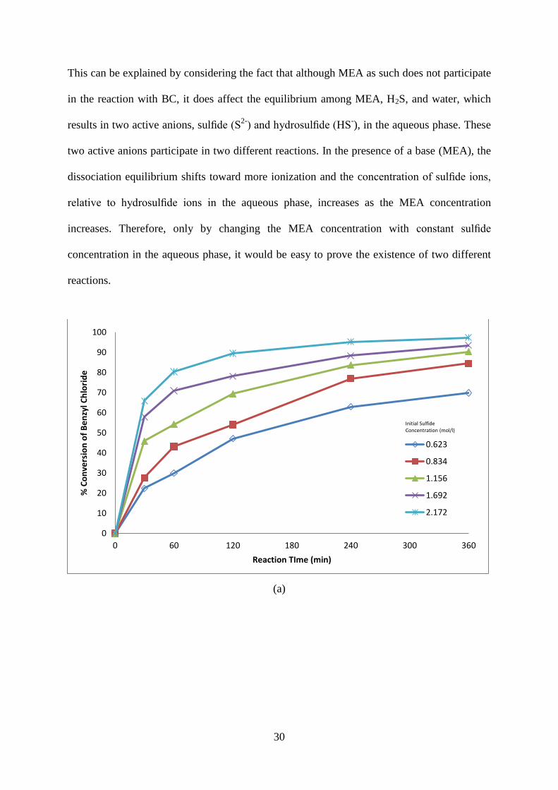
4.2.3 Effect of initial sulfide concentration
The effect of initial sulfide concentration on the conversion of BC and DBS selectivity was
studied keeping the MEA concentration fixed at 4.97 kmol/m3.
Keeping the MEA concentration constant, with the increase in initial sulfide concentration,
percentage conversion increased because more sulfide ions were available for reaction, as
shown in Figure 10(a). Conversion rates of up to 97% were achieved with initial sulfide
concentration of 2.172 kmol/m3.
However an opposite trend was observed in case of DBS selectivity. Here the DBS selectivity
actually decreased with an increase in initial sulfide concentration as shown in Figure 10(b).
0
5
10
15
20
25
30
35
40
0 60 120 180 240 300 360
% S
ele
ctiv
ity
of
DB
S
Reaction Time (min)
0%
1%
2%
5%
PEG Concentration
30
This can be explained by considering the fact that although MEA as such does not participate
in the reaction with BC, it does affect the equilibrium among MEA, H2S, and water, which
results in two active anions, sulfide (S2-
) and hydrosulfide (HS-), in the aqueous phase. These
two active anions participate in two different reactions. In the presence of a base (MEA), the
dissociation equilibrium shifts toward more ionization and the concentration of sulfide ions,
relative to hydrosulfide ions in the aqueous phase, increases as the MEA concentration
increases. Therefore, only by changing the MEA concentration with constant sulfide
concentration in the aqueous phase, it would be easy to prove the existence of two different
reactions.
(a)
0
10
20
30
40
50
60
70
80
90
100
0 60 120 180 240 300 360
% C
on
vers
ion
of
Be
nzy
l Ch
lori
de
Reaction TIme (min)
0.623
0.834
1.156
1.692
2.172
Initial Sulfide Concentration (mol/l)

31
(b)
Figure 10. Effect of initial sulfide concentration on (a) BC conversion (b) DBS
selectivity. Volume of organic phase = 5.0×10⁻⁵
m3; volume of aqueous phase = 5.0×10
−5
m3; concentration of catalyst = 2%; concentration of BC= 8.69 kmol/m
3; temperature = 303
K; stirring speed = 1500 rpm.
0
10
20
30
40
50
60
70
80
90
100
0 60 120 180 240 300 360
% S
ele
ctiv
ity
of
DB
S
Reaction Time (mins)
2.172
1.692
1.156
0.834
0.623
Initial Sulfide Concentration (mol/l)

32
Chapter 5
Conclusion

33
5. CONCLUSION
The reaction under study is an industrially important reaction as it produces products such as
dibenzyl sulfide and benzyl mercaptan which have varied industrial applications.
DBS finds applications in:
Additives for extreme pressure lubricants.
Anti-wear additives for motor oils.
Stabilizers for photographic emulsion.
In refining and recovery of precious metals.
Anticorrosive formulations
BM finds application in raw material for synthesis for herbicides in the thiocarbamate family
such as esprocarb, prosulfocarb, tiocarbazil, etc.
This reaction was investigated thoroughly but a few parameters could not be studied due to
technical handicaps. For the parameters that were examined, it was found that DBS can be
preferentially produced by increasing the catalyst concentration and by decreasing the initial
sulfide concentration. On the other hand, opposite trend was observed for BM which was the
dominant product in lower catalyst concentration and higher initial sulfide concentration.
When other factors such as temperature, BC concentration will be studied, we would enough
data to optimize the process and suggest a suitable reaction mechanism along with kinetic
model.

34
References

35
REFERENCES
[1] Maity S.K., Pradhan N.C. , Patwardhan A.V., Kinetics of the reduction of nitrotoluenes
by aq. ammonium sulfide under liquid-liquid phase transfer catalysis, Applied Catalysis A:
General 301 (2000), pp. 251-258
[2] Maity S.K., Pradhan N.C. , Patwardhan A.V., Reaction of benzyl chloride with
ammonium sulfide under liquid-liquid phase transfer catalysis: Reaction mechanism and
kinetics, Journal of Molecular Catalysis A: Chemical 250 (2006), pp. 114-121
[3] Maity S.K., Pradhan N.C. , Patwardhan A.V., Kinetics of reduction of nitrotoluenes by
H2S rich aqueous ethanolamine, Industrial and Engineering Research, 45 (2006), pp 7767-
7774
[4] Maity S.K., Pradhan N.C. , Patwardhan A.V., Reduction of o-nitroanisole to o-anisidine
by H2S rich aqueous diethanolamine: A novel method for utilization of H2S laden gas
streams, Chemical Engineering Science, 62 (2007), pp. 805-813
[5] Maity S.K., Pradhan N.C. , Patwardhan A.V., Kinetics of phase transfer catalyzed
reduction of nitrochlorobenzenes by aqueous ammonium sulfide: Utilization of hydrotreater
off-gas for the production of value-added chemicals, Applied Catalysis B: Environmental 77
(2008), pp. 418-426
[6] Maity S.K., Pradhan N.C. , Patwardhan A.V., Reduction of p-nitrotoluene by aqueous
ammonium sulfide: Anion exchange resin as a triphasic catalyst, Chemical Engineering
Journal 141 (2008), pp. 187-193
[7] Maity S.K., Sen S., Pradhan N.C. , A new mechanistic model for liquid-liquid phase
transfer catalysis: Reaction of benzyl chloride with aqueous ammonium sulfide, Chemical
Engineering Science 64 (2009), pp. 4365-4374

36
[8] Sen S., Maity S.K., Pradhan N.C. , Utilization of hydrogen sulfide for the synthesis of
dibenzyl sulfide: Effects of process parameters on conversion and selectivity, International
Journal of Chemical Science: 5 (4), 2007, pp. 1569-1578
[9] Pradhan N.C., Sharma M.M., Solid-Liquid reactions catalyzed by alumina and ion
exchange resin: Reactions of Benzyl Chloride/ p-Chlorobenzyl Chloride with solid sodium
sulfide, Industrial and Engineering Chemistry Research, 31 (1992), pp. 1610-1614
[10] Yadav G.D., Badure O.V., Role of third phase in intensification of reaction rates and
selectivity: Phase transfer catalyzed synthesis of benzyl phenyl ether, Industrial and
Engineering Chemistry Research, 46 (2007), pp. 8448-8458
[11] Kamal A., Reddy D.R., Rajendar, A simple and green procedure for the conjugate
addition of thiols to conjugated alkenes employing polyethylene glycol (PEG) as an efficient
recyclable medium, Tetrahedron Letters, 46 (2005), pp. 7951–7953
[12] Naik S.D., Doraiswamy L. K., Phase Transfer Catalysis:Chemistry and Engineering,
Reactors, Kinetics and Catalysis, 44 (1998), pp. 612-646
[13] Hamblin, R. Removal and Recovery of Sulfur from a Gas Stream Containing Hydrogen
Sulfide. Patent No. US3728441, 1973.
[14] Harvey, W. W.; Makrides, A.C. Process for Removing Hydrogen Sulfide and Ammonia
from Gaseous Streams. Patent No. US4192854, 1980.
[15] Kohl, A.L.; Nielsen, R.B. Gas purification, Gulf Publishing Company Houston, Texas,
1997.
[16] Plummer, M.A. Process for Recovering Sulfur and Hydrogen from Hydrogen Sulfide.
Patent No. WO9412431, 1994.
[17] Plummer, M.A.; Beazley, P.M. Conversion of Hydrogen Sulfide to Sulfur and
Hydrogen. Patent Number US4592905, 1986.

37
[18] Plummer, M.A.; Zimmerman, Jr Carle C. Hydrocarbon Desulfurization Process. Patent
Number US4581128, 1986.
[19] Starks, C. M. Phase Transfer Catalysis. I. Heterogeneous Reactions Involving Anion
Transfer by Quaternary Ammonium and Phosphonium Salts. Journal of the American
Chemical Society 1971, 93, 195-199.
[20] Starks, C. M.; Liotta, C. L. Phase-Transfer Catalysis Principles and Techniques,
Academic: New York, 1978.
[21] Dehmlow, E. V.; Dehmlow, S. S. Phase Transfer Catalysis, 2nd ed., Verlag Chemie
Weinheim, 1983.