destruction of dibenzyl disulfide in … dbds destruction paper 2008.pdfdestruction of dibenzyl...
TRANSCRIPT

© 2008 Doble Engineering Company -75th Annual International Doble Client Conference All Rights Reserved
DESTRUCTION OF DIBENZYL DISULFIDE IN TRANSFORMER OIL
Lance Lewand Doble Engineering Company
Scott Reed
Power Substation Services ABSTRACT Dibenzyl Disulfide (DBDS) is one of several sulfur compounds known to cause copper corrosion in transformers under certain circumstances. Remedial processes such as adsorbents, absorbents, and oil change-out have been known to reduce the concentration of DBDS in the oil. However, if not destroyed or removed below several mg/kg (ppm), breakdown of the DBDS to benzyl mercaptan or a DBDS-Copper complex can still cause corrosion of copper and the formation of copper sulfide. Passivators are also being used to protect the copper against corrosive sulfur attack but does not remove or destroy any corrosive sulfur species or those sulfur compounds that can become corrosive. This paper discusses a process in which the destruction of DBDS is complete to below 1 mg/kg, can be performed at the transformer, and the oil reused in the same unit. INTRODUCTION There is not one single corrosive sulfur compound that is responsible for all corrosive sulfur issues that are present in all mineral oil filled electrical apparatus. Depending on the oil, there can be tens to hundreds of different sulfur compounds present in the oil. Of these, only a small fraction are corrosive or are compounds that can degrade from stable species into ones that are reactive. This is usually based on time and temperature. Only a very few corrosive sulfur compounds have been identified of which dibenzyl disulfide (DBDS) is one. This paper only concentrates on DBDS. The reason is that it has been found in many oils that have resulted in recent failures (2000-2007) of transformers or reactors due to corrosive sulfur attack and the formation of copper sulfide. There are five main classes of sulfur compounds found in crude oil but not all types are considered to be corrosive or reactive (see Table 1)[1]. Elemental sulfur and sulfur compounds in concentrations up to 20% [2] are present in the crude oil used to make transformer oil.
TABLE 1 Sulfur and Sulfur Compounds Found in Crude Oil
GROUP REACTIVITY CHEMICAL FORMULA Elemental (Free) Sulfur Very Reactive S Mercaptans (thiols) Very Reactive R-SH Sulfides (thio-ethers) Reactive R-S-R1 Disulfides Reactive/Stable R-S•S-R Thiophenes Very Stable Five-member ring containing sulfur
R=paraffin with straight or branched chain hydrocarbon or cyclic hydrocarbon Sulfur is commonly found in crude oil, as it is a common element in the earth’s crust. As shown in Table 1, elemental sulfur and the sulfur-containing mercaptans are very reactive followed by sulfides. Reactive
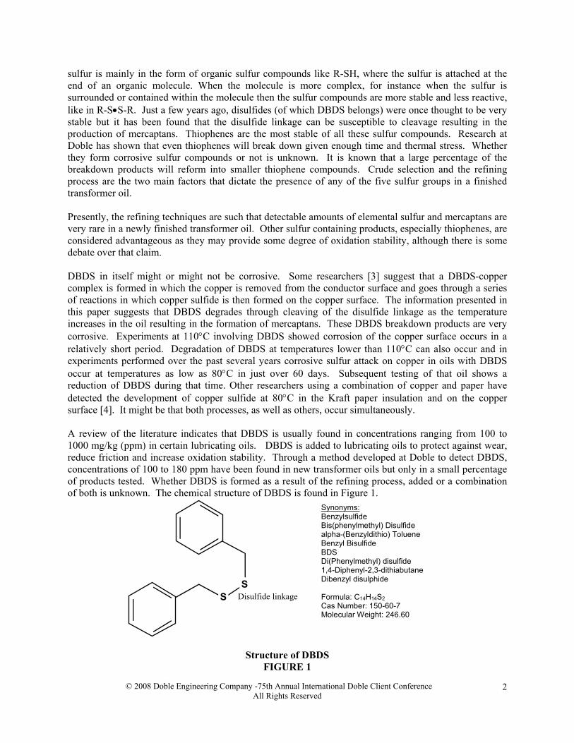
sulfur is mainly in the form of organic sulfur compounds like R-SH, where the sulfur is attached at the end of an organic molecule. When the molecule is more complex, for instance when the sulfur is surrounded or contained within the molecule then the sulfur compounds are more stable and less reactive, like in R-S•S-R. Just a few years ago, disulfides (of which DBDS belongs) were once thought to be very stable but it has been found that the disulfide linkage can be susceptible to cleavage resulting in the production of mercaptans. Thiophenes are the most stable of all these sulfur compounds. Research at Doble has shown that even thiophenes will break down given enough time and thermal stress. Whether they form corrosive sulfur compounds or not is unknown. It is known that a large percentage of the breakdown products will reform into smaller thiophene compounds. Crude selection and the refining process are the two main factors that dictate the presence of any of the five sulfur groups in a finished transformer oil. Presently, the refining techniques are such that detectable amounts of elemental sulfur and mercaptans are very rare in a newly finished transformer oil. Other sulfur containing products, especially thiophenes, are considered advantageous as they may provide some degree of oxidation stability, although there is some debate over that claim. DBDS in itself might or might not be corrosive. Some researchers [3] suggest that a DBDS-copper complex is formed in which the copper is removed from the conductor surface and goes through a series of reactions in which copper sulfide is then formed on the copper surface. The information presented in this paper suggests that DBDS degrades through cleaving of the disulfide linkage as the temperature increases in the oil resulting in the formation of mercaptans. These DBDS breakdown products are very corrosive. Experiments at 110°C involving DBDS showed corrosion of the copper surface occurs in a relatively short period. Degradation of DBDS at temperatures lower than 110°C can also occur and in experiments performed over the past several years corrosive sulfur attack on copper in oils with DBDS occur at temperatures as low as 80°C in just over 60 days. Subsequent testing of that oil shows a reduction of DBDS during that time. Other researchers using a combination of copper and paper have detected the development of copper sulfide at 80°C in the Kraft paper insulation and on the copper surface [4]. It might be that both processes, as well as others, occur simultaneously. A review of the literature indicates that DBDS is usually found in concentrations ranging from 100 to 1000 mg/kg (ppm) in certain lubricating oils. DBDS is added to lubricating oils to protect against wear, reduce friction and increase oxidation stability. Through a method developed at Doble to detect DBDS, concentrations of 100 to 180 ppm have been found in new transformer oils but only in a small percentage of products tested. Whether DBDS is formed as a result of the refining process, added or a combination of both is unknown. The chemical structure of DBDS is found in Figure 1.
SS
Disulfide linkage
Synonyms:BenzylsulfideBis(phenylmethyl) Disulfidealpha-(Benzyldithio) TolueneBenzyl BisulfideBDSDi(Phenylmethyl) disulfide1,4-Diphenyl-2,3-dithiabutaneDibenzyl disulphide
Formula: C14H14S2Cas Number: 150-60-7Molecular Weight: 246.60
Structure of DBDS
FIGURE 1
© 2008 Doble Engineering Company -75th Annual International Doble Client Conference All Rights Reserved
2
The focus on DBDS is not without reasons. They are: • The degradation byproducts have been shown to be corrosive • Many oils involved in recent failures due to corrosive sulfur have had high concentrations of DBDS • Trending analysis of DBDS in highly loaded transformers shows a reduction of its concentration with
time • Laboratory analysis of oils spiked with DBDS has shown that as DBDS concentrations decline the
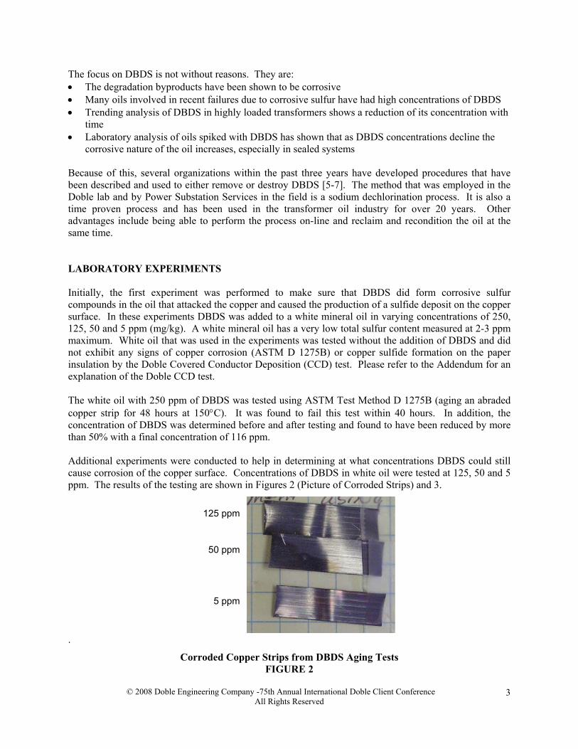
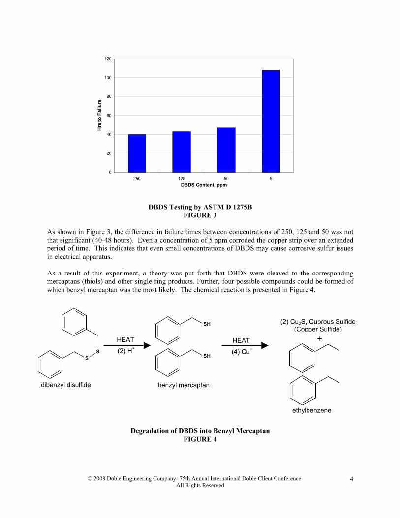
corrosive nature of the oil increases, especially in sealed systems Because of this, several organizations within the past three years have developed procedures that have been described and used to either remove or destroy DBDS [5-7]. The method that was employed in the Doble lab and by Power Substation Services in the field is a sodium dechlorination process. It is also a time proven process and has been used in the transformer oil industry for over 20 years. Other advantages include being able to perform the process on-line and reclaim and recondition the oil at the same time. LABORATORY EXPERIMENTS Initially, the first experiment was performed to make sure that DBDS did form corrosive sulfur compounds in the oil that attacked the copper and caused the production of a sulfide deposit on the copper surface. In these experiments DBDS was added to a white mineral oil in varying concentrations of 250, 125, 50 and 5 ppm (mg/kg). A white mineral oil has a very low total sulfur content measured at 2-3 ppm maximum. White oil that was used in the experiments was tested without the addition of DBDS and did not exhibit any signs of copper corrosion (ASTM D 1275B) or copper sulfide formation on the paper insulation by the Doble Covered Conductor Deposition (CCD) test. Please refer to the Addendum for an explanation of the Doble CCD test. The white oil with 250 ppm of DBDS was tested using ASTM Test Method D 1275B (aging an abraded copper strip for 48 hours at 150°C). It was found to fail this test within 40 hours. In addition, the concentration of DBDS was determined before and after testing and found to have been reduced by more than 50% with a final concentration of 116 ppm. Additional experiments were conducted to help in determining at what concentrations DBDS could still cause corrosion of the copper surface. Concentrations of DBDS in white oil were tested at 125, 50 and 5 ppm. The results of the testing are shown in Figures 2 (Picture of Corroded Strips) and 3.
5 ppm
50 ppm
125 ppm
.
Corroded Copper Strips from DBDS Aging Tests FIGURE 2
© 2008 Doble Engineering Company -75th Annual International Doble Client Conference All Rights Reserved
3
0
20
40
60
80
100
120
250 125 50 5DBDS Content, ppm
Hrs
to F
ailu
re
DBDS Testing by ASTM D 1275B FIGURE 3
As shown in Figure 3, the difference in failure times between concentrations of 250, 125 and 50 was not that significant (40-48 hours). Even a concentration of 5 ppm corroded the copper strip over an extended period of time. This indicates that even small concentrations of DBDS may cause corrosive sulfur issues in electrical apparatus. As a result of this experiment, a theory was put forth that DBDS were cleaved to the corresponding mercaptans (thiols) and other single-ring products. Further, four possible compounds could be formed of which benzyl mercaptan was the most likely. The chemical reaction is presented in Figure 4.
SS
HEAT
(2) H+
SH
SH
(2) Cu2S, Cuprous Sulfide (Copper Sulfide)
+
ethylbenzene
(4) Cu+
HEAT
dibenzyl disulfide benzyl mercaptan
Degradation of DBDS into Benzyl Mercaptan
FIGURE 4
© 2008 Doble Engineering Company -75th Annual International Doble Client Conference All Rights Reserved
4

Benzyl mercaptan is very volatile and would not ordinarily be present in a newly refined transformer oil, as it would be easily removed. However, once produced, there is no escape in a well-sealed transformer. It is very oil soluble and is very reactive to copper and silver surfaces. The same is not true in open conservator transformers where oxygen is present in higher concentrations. It was concluded that degradation of organic sulfur compounds involves an oxidative attack localized at the sulfur atom [8]. As a result, benzyl mercaptan molecules are oxidized and some DBDS is actually reformed. Some of the benzyl mercaptan is likely lost through the free breathing nature of the conservator. Copper sulfide is formed but at least half or less than what would be formed in a sealed transformer. This chemical reaction is shown in Figure 5. It is most likely that some water is also formed, but the amount would be so minute in comparison to the water content already existing in the transformer, it would be indistinguishable.
SS
SH
SH
SS
Oxidation
Cu2S, Cuprous Sulfide (Copper Sulfide)
(2) Cu+
HEATHEAT
dibenzyl disulfide
(2) H+
benzyl mercaptan
+ H2O
Oxidation Reaction of Benzyl Mercaptan FIGURE 5
A similar study using benzyl mercaptan instead of DBDS indicates that the reaction rate with the copper is very accelerated at more than twice as fast when compared to DBDS at 150°C. Refer to Figure 6.
0
5
10
15
20
25
30
35
40
45
50
DBDS benzyl mercaptan
Sulfur Compunds, 125 mg/kg
Tim
e to
Fai
lure
, Hou
rs
Rate of Formation of Copper Sulfide, ASTM D 1275B Test FIGURE 6
© 2008 Doble Engineering Company -75th Annual International Doble Client Conference All Rights Reserved
5
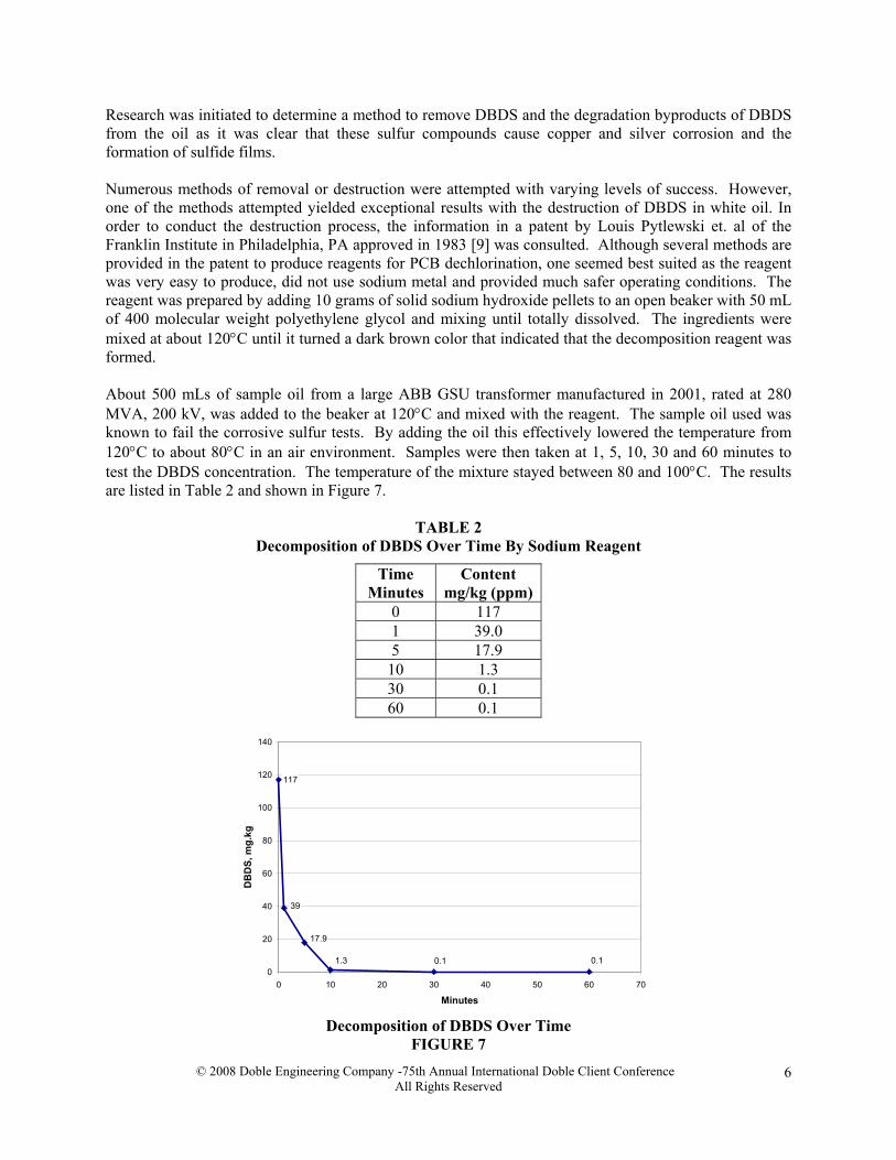
Research was initiated to determine a method to remove DBDS and the degradation byproducts of DBDS from the oil as it was clear that these sulfur compounds cause copper and silver corrosion and the formation of sulfide films. Numerous methods of removal or destruction were attempted with varying levels of success. However, one of the methods attempted yielded exceptional results with the destruction of DBDS in white oil. In order to conduct the destruction process, the information in a patent by Louis Pytlewski et. al of the Franklin Institute in Philadelphia, PA approved in 1983 [9] was consulted. Although several methods are provided in the patent to produce reagents for PCB dechlorination, one seemed best suited as the reagent was very easy to produce, did not use sodium metal and provided much safer operating conditions. The reagent was prepared by adding 10 grams of solid sodium hydroxide pellets to an open beaker with 50 mL of 400 molecular weight polyethylene glycol and mixing until totally dissolved. The ingredients were mixed at about 120°C until it turned a dark brown color that indicated that the decomposition reagent was formed. About 500 mLs of sample oil from a large ABB GSU transformer manufactured in 2001, rated at 280 MVA, 200 kV, was added to the beaker at 120°C and mixed with the reagent. The sample oil used was known to fail the corrosive sulfur tests. By adding the oil this effectively lowered the temperature from 120°C to about 80°C in an air environment. Samples were then taken at 1, 5, 10, 30 and 60 minutes to test the DBDS concentration. The temperature of the mixture stayed between 80 and 100°C. The results are listed in Table 2 and shown in Figure 7.
TABLE 2 Decomposition of DBDS Over Time By Sodium Reagent
Time Minutes
Content mg/kg (ppm)
0 117 1 39.0 5 17.9
10 1.3 30 0.1 60 0.1
117
0.10.11.3
17.9
39
0
20
40
60
80
100
120
140
0 10 20 30 40 50 60 7
Minutes
DB
DS,
mg.
kg
0
Decomposition of DBDS Over Time FIGURE 7
© 2008 Doble Engineering Company -75th Annual International Doble Client Conference All Rights Reserved
6
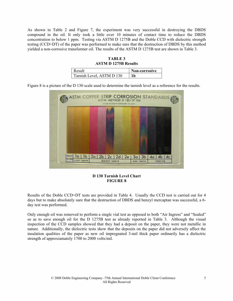
As shown in Table 2 and Figure 7, the experiment was very successful in destroying the DBDS compound in the oil. It only took a little over 10 minutes of contact time to reduce the DBDS concentration to below 1 ppm. Testing via ASTM D 1275B and the Doble CCD with dielectric strength testing (CCD+DT) of the paper was performed to make sure that the destruction of DBDS by this method yielded a non-corrosive transformer oil. The results of the ASTM D 1275B test are shown in Table 3.
TABLE 3 ASTM D 1275B Results
Result Non-corrosive Tarnish Level, ASTM D 130 1b
Figure 8 is a picture of the D 130 scale used to determine the tarnish level as a reference for the results.
D 130 Tarnish Level Chart
FIGURE 8 Results of the Doble CCD+DT tests are provided in Table 4. Usually the CCD test is carried out for 4 days but to make absolutely sure that the destruction of DBDS and benzyl mercaptan was successful, a 6-day test was performed. Only enough oil was removed to perform a single vial test as opposed to both “Air Ingress” and “Sealed” so as to save enough oil for the D 1275B test as already reported in Table 3. Although the visual inspection of the CCD samples showed that they had a deposit on the paper, they were not metallic in nature. Additionally, the dielectric tests show that the deposits on the paper did not adversely affect the insulation qualities of the paper as new oil impregnated 3-mil thick paper ordinarily has a dielectric strength of approxiamately 1700 to 2000 volts/mil.
© 2008 Doble Engineering Company -75th Annual International Doble Client Conference All Rights Reserved
7

TABLE 4 Doble CCD+DT Results (Covered Conductor Deposition and Paper Dielectric Strength Testing)
CCD, Air Ingress Vial After 15 minutes of Lab sodium alkalai procesing Copper rod, Doble Non-corrosive, Tarnish level 1b Breakdown Voltage, ASTM D 149 10,000 volts Dielectric Strength, ASTM D 149 1670 volts/mil CCD, Sealed Vial After 30 minutes of Lab sodium alkalai procesing Copper rod, Doble Non-corrosive, Tarnish level 1b Breakdown Voltage, ASTM D 149 10,800 volts Dielectric Strength, ASTM D 149 1800 volts/mil CCD, Air Ingress Vial After 60 minutes of Lab sodium alkalai procesing Copper rod, Doble Non-corrosive, Tarnish level 1b Breakdown Voltage, ASTM D 149 10,800 volts Dielectric Strength, ASTM D 149 1800 volts/mil
Two additional processes were conducted after the original soldium alkalai treatment. Thery were: • Processing the oil through Fuller’s earth (clay) • Addition of oxidation inhbitor (DBPC/BHT)
In the laboratory, the processing of the treated oil through Fuller’s Earth (clay) was conducted at a treat rate of 0.25 pounds of clay per gallon of oil or 0.03 kg/L. The oil was processed under nitrogen at a temperature ranging from 60 to 70°C. The results are shown in Table 5.
TABLE 5 Doble CCD Results after Alkalai Sodium and Clay Treament (CCD 6-day test)
Test Specimen RESULTS Copper Rod, Air Ingress Vial, No Inhibitor Non-corrosive, Tarnish level 3a Paper Insulation, Air Ingress Vial, No Inhibitor Light olive green deposit Copper Rod, Sealed Vial, No Inhibitor Non-corrosive, Tarnish level 3a Paper Insulation, Sealed Vial, No Inhibitor No Deposition
The synthetic inhibitor DBPC (BHT) was added to the processed oils at concentrations of 0.15 and 0.30% and compared to oil that was also clay treated but with no added inhibitor. A 6-day CCD Test was performed. The results are provided in Table 6. Inhibitor is very rarely related to the formation or inhibition of corrosive sulfur. In these cases the dull deposits in the samples with no inhbitor or 0.15% inhibitor are most likely from the oxidation byproducts of the oil. The additional inhbitor to the 0.30% level may have helped prevent those byproducts and thus the deposition from occurring. Testing showed that the deposits were not composed of elevated levels of copper and sulfur.
© 2008 Doble Engineering Company -75th Annual International Doble Client Conference All Rights Reserved
8
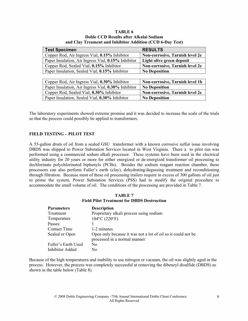
TABLE 6 Doble CCD Results after Alkalai Sodium
and Clay Treament and Inhibitor Addition (CCD 6-Day Test)
Test Specimen RESULTS Copper Rod, Air Ingress Vial, 0.15% Inhibitor Non-corrosive, Tarnish level 2e Paper Insulation, Air Ingress Vial, 0.15% Inhibitor Light olive green deposit Copper Rod, Sealed Vial, 0.15% Inhibitor Non-corrosive, Tarnish level 2e Paper Insulation, Sealed Vial, 0.15% Inhibitor No Deposition Copper Rod, Air Ingress Vial, 0.30% Inhibitor Non-corrosive, Tarnish level 1b Paper Insulation, Air Ingress Vial, 0.30% Inhibitor No Deposition Copper Rod, Sealed Vial, 0.30% Inhibitor Non-corrosive, Tarnish level 2e Paper Insulation, Sealed Vial, 0.30% Inhibitor No Deposition
The laboratory experiments showed extreme promise and it was decided to increase the scale of the trials so that the process could possibly be applied to transformers. FIELD TESTING – PILOT TEST A 55-gallon drum of oil from a sealed GSU transformer with a known corrosive sulfur issue involving DBDS was shipped to Power Substation Services located in West Virginia. There a to pilot run was performed using a commercial sodum alkali processor. These systems have been used in the electrical utility industry for 20 years or more for either energized or de-energized transformer oil processing to dechlorinate polychlorinated biphenyls (PCBs). Besides the sodium reagant reaction chamber, these processors can also perform Fuller’s earth (clay), dehydrating/degassing treatment and reconditioning through filtration. Because most of these oil processing trailers require in excess of 300 gallons of oil just to prime the system, Power Substation Services (PSS) had to modify the original procedure to accommodate the small volume of oil. The conditions of the processing are provided in Table 7.
TABLE 7 Field Pilot Treatment for DBDS Destruction
Parameters Description Treatment Proprietary alkali process using sodium Temperature 104°C (220°F) Passes 1 Contact Time 1-2 minutes Sealed or Open Open only because it was not a lot of oil so it could not be
processed in a normal manner Fuller’s Earth Used No Inhibitor Added No
Because of the high temperatures and inability to use nitrogen or vacuum, the oil was slightly aged in the process. However, the process was completely successful at removing the dibenzyl disulfide (DBDS) as shown in the table below (Table 8).
© 2008 Doble Engineering Company -75th Annual International Doble Client Conference All Rights Reserved
9
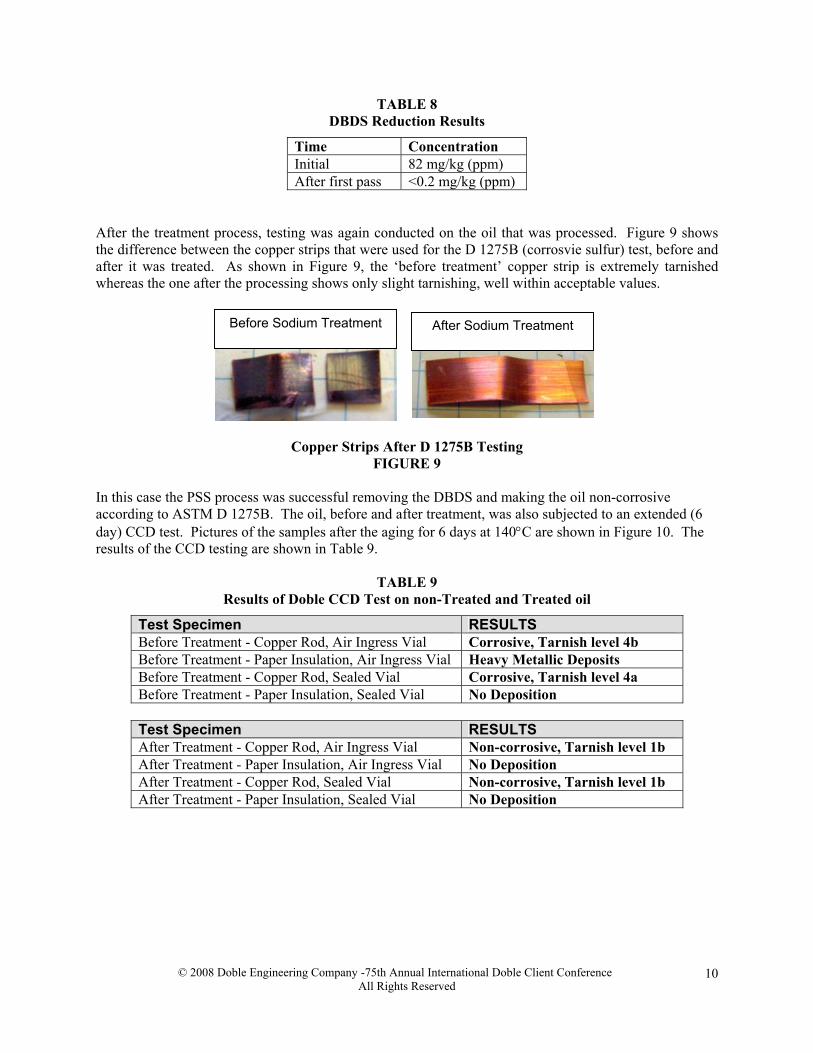
TABLE 8 DBDS Reduction Results
Time Concentration Initial 82 mg/kg (ppm) After first pass <0.2 mg/kg (ppm)
After the treatment process, testing was again conducted on the oil that was processed. Figure 9 shows the difference between the copper strips that were used for the D 1275B (corrosvie sulfur) test, before and after it was treated. As shown in Figure 9, the ‘before treatment’ copper strip is extremely tarnished whereas the one after the processing shows only slight tarnishing, well within acceptable values.
Before Sodium Treatment After Sodium Treatment
Copper Strips After D 1275B Testing
FIGURE 9 In this case the PSS process was successful removing the DBDS and making the oil non-corrosive according to ASTM D 1275B. The oil, before and after treatment, was also subjected to an extended (6 day) CCD test. Pictures of the samples after the aging for 6 days at 140°C are shown in Figure 10. The results of the CCD testing are shown in Table 9.
TABLE 9 Results of Doble CCD Test on non-Treated and Treated oil
Test Specimen RESULTS Before Treatment - Copper Rod, Air Ingress Vial Corrosive, Tarnish level 4b Before Treatment - Paper Insulation, Air Ingress Vial Heavy Metallic Deposits Before Treatment - Copper Rod, Sealed Vial Corrosive, Tarnish level 4a Before Treatment - Paper Insulation, Sealed Vial No Deposition
Test Specimen RESULTS After Treatment - Copper Rod, Air Ingress Vial Non-corrosive, Tarnish level 1b After Treatment - Paper Insulation, Air Ingress Vial No Deposition After Treatment - Copper Rod, Sealed Vial Non-corrosive, Tarnish level 1b After Treatment - Paper Insulation, Sealed Vial No Deposition
© 2008 Doble Engineering Company -75th Annual International Doble Client Conference All Rights Reserved
10
AFTER Sodium Treatment
Sealed Vial Air Ingress
BEFORE Sodium Treatment
Sealed VialAir Ingress
Results of Doble CCD Tests (140°C, 6 days) FIGURE 10
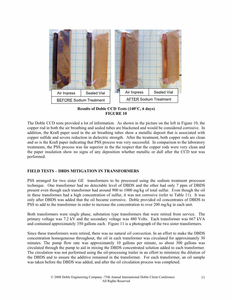
The Doble CCD tests provided a lot of information. As shown in the picture on the left in Figure 10, the copper rod in both the air breathing and sealed tubes are blackened and would be considered corrosive. In addition, the Kraft paper used in the air breathing tubes show a metallic deposit that is associated with copper sulfide and severe reduction in dielectric strength. After the treatment, both copper rods are clean and so is the Kraft paper indicating that PSS process was very successful. In comparison to the laboratory treatments, the PSS process was far superior in the the respect that the copper rods were very clean and the paper insulation show no signs of any deposition whether metallic or dull after the CCD test was performed. FIELD TESTS – DBDS MITIGATION IN TRANSFORMERS PSS arranged for two sister GE transformers to be processed using the sodium treatment processor technique. One transformer had no detectable level of DBDS and the other had only 7 ppm of DBDS present even though each transformer had around 900 to 1000 mg/kg of total sulfur. Even though the oil in these transformes had a high concentration of sulfur, it was not corrosive (refer to Table 11). It was only after DBDS was added that the oil became corrosive. Doble provided oil concentrates of DBDS to PSS to add to the transformer in order to increase the concentration to over 200 mg/kg in each unit. Both transformers were single phase, substation type transformers that were retired from service. The primary voltage was 7.2 kV and the secondary voltage was 480 Volts. Each transformer was 667 kVA and contained approximately 350 gallons each. Figure 11 is a photograph of the two sister transformers. Since these transformers were retired, there was no natural oil convection. In an effort to make the DBDS concentration homogeneous throughout, the oil in each transformer was circulated for approximately 30 minutes. The pump flow rate was approximately 10 gallons per minute, so about 300 gallons was circulated through the pump to aid in mixing the DBDS concentrated solution added to each transformer. The circulation was not performed using the oil-processing trailer in an effort to minimize the dilution of the DBDS and to ensure the additive remained in the transformer. For each transformer, an oil sample was taken before the DBDS was added, and after the oil circulation process was completed.
© 2008 Doble Engineering Company -75th Annual International Doble Client Conference All Rights Reserved
11
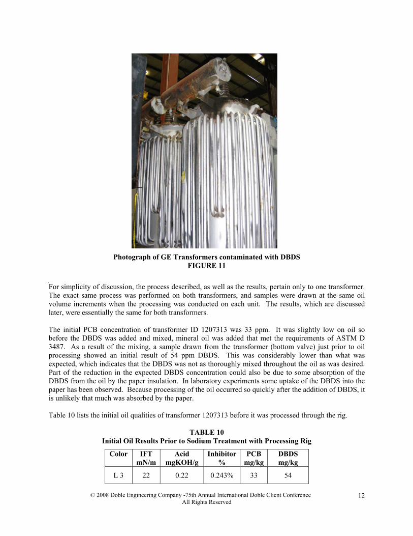
Photograph of GE Transformers contaminated with DBDS FIGURE 11
For simplicity of discussion, the process described, as well as the results, pertain only to one transformer. The exact same process was performed on both transformers, and samples were drawn at the same oil volume increments when the processing was conducted on each unit. The results, which are discussed later, were essentially the same for both transformers. The initial PCB concentration of transformer ID 1207313 was 33 ppm. It was slightly low on oil so before the DBDS was added and mixed, mineral oil was added that met the requirements of ASTM D 3487. As a result of the mixing, a sample drawn from the transformer (bottom valve) just prior to oil processing showed an initial result of 54 ppm DBDS. This was considerably lower than what was expected, which indicates that the DBDS was not as thoroughly mixed throughout the oil as was desired. Part of the reduction in the expected DBDS concentration could also be due to some absorption of the DBDS from the oil by the paper insulation. In laboratory experiments some uptake of the DBDS into the paper has been observed. Because processing of the oil occurred so quickly after the addition of DBDS, it is unlikely that much was absorbed by the paper. Table 10 lists the initial oil qualities of transformer 1207313 before it was processed through the rig.
TABLE 10 Initial Oil Results Prior to Sodium Treatment with Processing Rig
Color IFT mN/m
Acid mgKOH/g
Inhibitor%
PCB mg/kg
DBDS mg/kg
L 3 22 0.22 0.243% 33 54
© 2008 Doble Engineering Company -75th Annual International Doble Client Conference All Rights Reserved
12
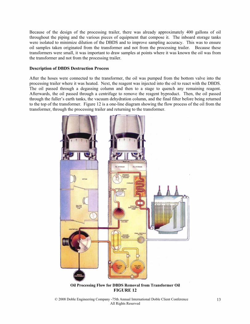
Because of the design of the processing trailer, there was already approximately 400 gallons of oil throughout the piping and the various pieces of equipment that compose it. The inboard storage tanks were isolated to minimize dilution of the DBDS and to improve sampling accuracy. This was to ensure oil samples taken originated from the transformer and not from the processing trailer. Because these transformers were small, it was important to draw samples at points where it was known the oil was from the transformer and not from the processing trailer. Description of DBDS Destruction Process After the hoses were connected to the transformer, the oil was pumped from the bottom valve into the processing trailer where it was heated. Next, the reagent was injected into the oil to react with the DBDS. The oil passed through a degassing column and then to a stage to quench any remaining reagent. Afterwards, the oil passed through a centrifuge to remove the reagent byproduct. Then, the oil passed through the fuller’s earth tanks, the vacuum dehydration column, and the final filter before being returned to the top of the transformer. Figure 12 is a one-line diagram showing the flow process of the oil from the transformer, through the processing trailer and returning to the transformer.
Oil Processing Flow for DBDS Removal from Transformer Oil FIGURE 12
© 2008 Doble Engineering Company -75th Annual International Doble Client Conference All Rights Reserved
13
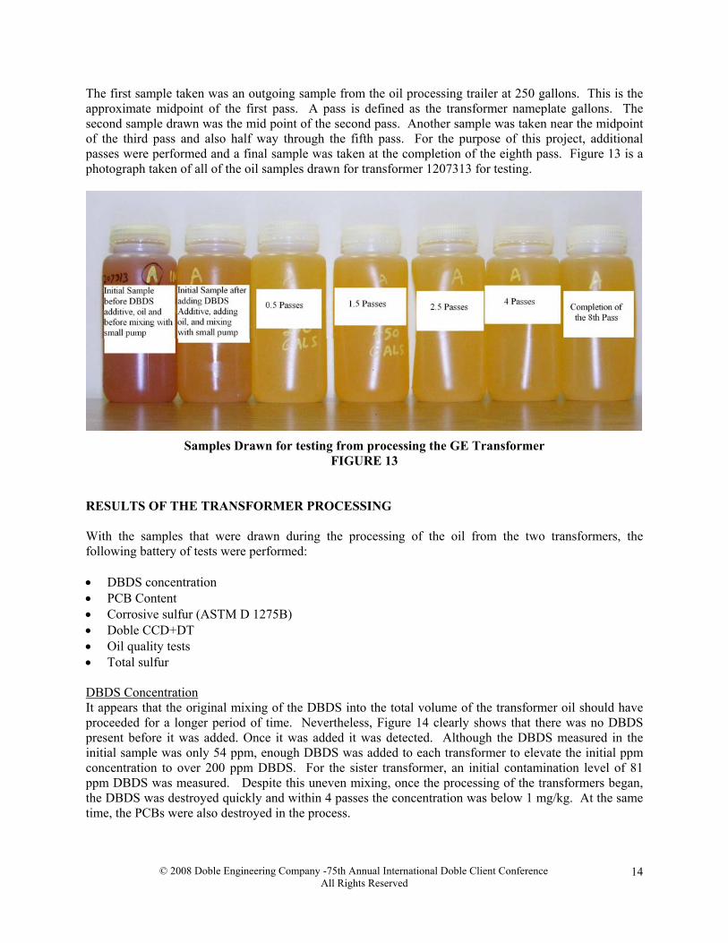
The first sample taken was an outgoing sample from the oil processing trailer at 250 gallons. This is the approximate midpoint of the first pass. A pass is defined as the transformer nameplate gallons. The second sample drawn was the mid point of the second pass. Another sample was taken near the midpoint of the third pass and also half way through the fifth pass. For the purpose of this project, additional passes were performed and a final sample was taken at the completion of the eighth pass. Figure 13 is a photograph taken of all of the oil samples drawn for transformer 1207313 for testing.
Samples Drawn for testing from processing the GE Transformer
FIGURE 13
RESULTS OF THE TRANSFORMER PROCESSING With the samples that were drawn during the processing of the oil from the two transformers, the following battery of tests were performed: • DBDS concentration • PCB Content • Corrosive sulfur (ASTM D 1275B) • Doble CCD+DT • Oil quality tests • Total sulfur DBDS Concentration It appears that the original mixing of the DBDS into the total volume of the transformer oil should have proceeded for a longer period of time. Nevertheless, Figure 14 clearly shows that there was no DBDS present before it was added. Once it was added it was detected. Although the DBDS measured in the initial sample was only 54 ppm, enough DBDS was added to each transformer to elevate the initial ppm concentration to over 200 ppm DBDS. For the sister transformer, an initial contamination level of 81 ppm DBDS was measured. Despite this uneven mixing, once the processing of the transformers began, the DBDS was destroyed quickly and within 4 passes the concentration was below 1 mg/kg. At the same time, the PCBs were also destroyed in the process.
© 2008 Doble Engineering Company -75th Annual International Doble Client Conference All Rights Reserved
14
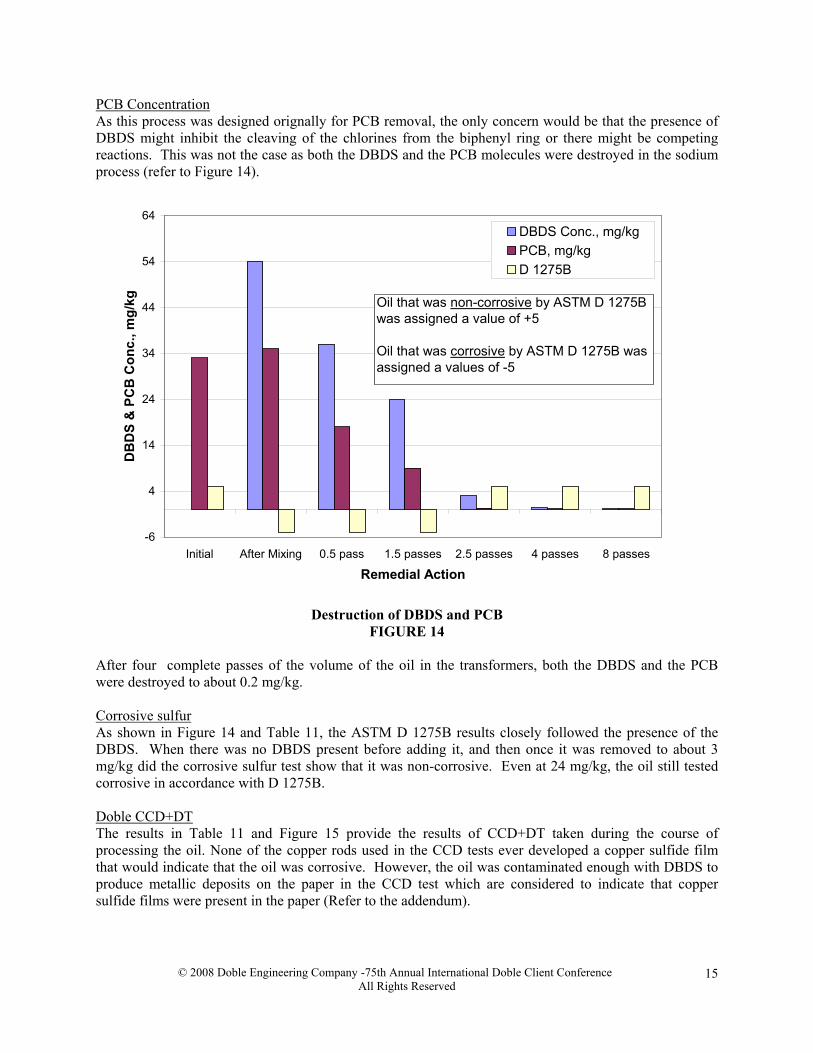
PCB Concentration As this process was designed orignally for PCB removal, the only concern would be that the presence of DBDS might inhibit the cleaving of the chlorines from the biphenyl ring or there might be competing reactions. This was not the case as both the DBDS and the PCB molecules were destroyed in the sodium process (refer to Figure 14).
-6
4
14
24
34
44
54
64
Initial After Mixing 0.5 pass 1.5 passes 2.5 passes 4 passes 8 passes
Remedial Action
DB
DS
& P
CB
Con
c., m
g/kg
DBDS Conc., mg/kgPCB, mg/kgD 1275B
Oil that was non-corrosive by ASTM D 1275B was assigned a value of +5
Oil that was corrosive by ASTM D 1275B was assigned a values of -5
Destruction of DBDS and PCB
FIGURE 14 After four complete passes of the volume of the oil in the transformers, both the DBDS and the PCB were destroyed to about 0.2 mg/kg. Corrosive sulfur As shown in Figure 14 and Table 11, the ASTM D 1275B results closely followed the presence of the DBDS. When there was no DBDS present before adding it, and then once it was removed to about 3 mg/kg did the corrosive sulfur test show that it was non-corrosive. Even at 24 mg/kg, the oil still tested corrosive in accordance with D 1275B. Doble CCD+DT The results in Table 11 and Figure 15 provide the results of CCD+DT taken during the course of processing the oil. None of the copper rods used in the CCD tests ever developed a copper sulfide film that would indicate that the oil was corrosive. However, the oil was contaminated enough with DBDS to produce metallic deposits on the paper in the CCD test which are considered to indicate that copper sulfide films were present in the paper (Refer to the addendum).
© 2008 Doble Engineering Company -75th Annual International Doble Client Conference All Rights Reserved
15
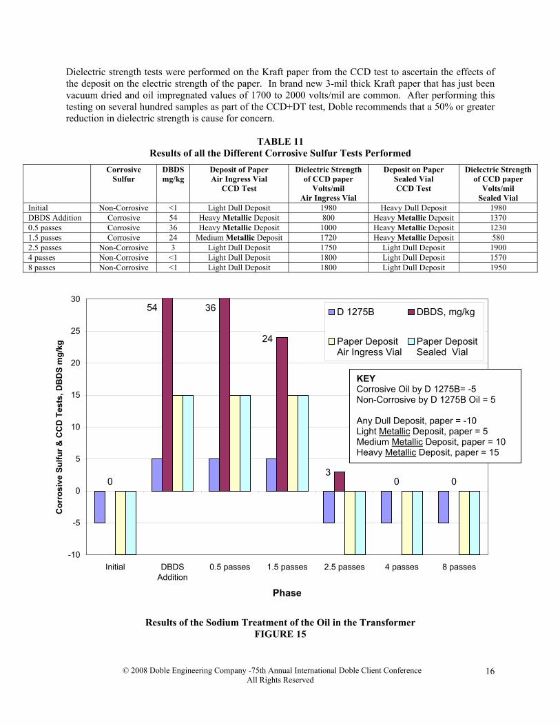
Dielectric strength tests were performed on the Kraft paper from the CCD test to ascertain the effects of the deposit on the electric strength of the paper. In brand new 3-mil thick Kraft paper that has just been vacuum dried and oil impregnated values of 1700 to 2000 volts/mil are common. After performing this testing on several hundred samples as part of the CCD+DT test, Doble recommends that a 50% or greater reduction in dielectric strength is cause for concern.
TABLE 11 Results of all the Different Corrosive Sulfur Tests Performed
Corrosive Sulfur
DBDS mg/kg
Deposit of Paper Air Ingress Vial
CCD Test
Dielectric Strength of CCD paper
Volts/mil Air Ingress Vial
Deposit on Paper Sealed Vial CCD Test
Dielectric Strength of CCD paper
Volts/mil Sealed Vial
Initial Non-Corrosive <1 Light Dull Deposit 1980 Heavy Dull Deposit 1980 DBDS Addition Corrosive 54 Heavy Metallic Deposit 800 Heavy Metallic Deposit 1370 0.5 passes Corrosive 36 Heavy Metallic Deposit 1000 Heavy Metallic Deposit 1230 1.5 passes Corrosive 24 Medium Metallic Deposit 1720 Heavy Metallic Deposit 580 2.5 passes Non-Corrosive 3 Light Dull Deposit 1750 Light Dull Deposit 1900 4 passes Non-Corrosive <1 Light Dull Deposit 1800 Light Dull Deposit 1570 8 passes Non-Corrosive <1 Light Dull Deposit 1800 Light Dull Deposit 1950
0 0 03
24
3654
-10
-5
0
5
10
15
20
25
30
Initial DBDSAddition
0.5 passes 1.5 passes 2.5 passes 4 passes 8 passes
Phase
Cor
rosi
ve S
ulfu
r & C
CD
Tes
ts, D
BD
S m
g/kg
D 1275B DBDS, mg/kg
Paper DepositAir Ingress Vial
Paper DepositSealed Vial
KEY Corrosive Oil by D 1275B= -5 Non-Corrosive by D 1275B Oil = 5 Any Dull Deposit, paper = -10 Light Metallic Deposit, paper = 5 Medium Metallic Deposit, paper = 10 Heavy Metallic Deposit, paper = 15
Results of the Sodium Treatment of the Oil in the Transformer
FIGURE 15
© 2008 Doble Engineering Company -75th Annual International Doble Client Conference All Rights Reserved
16
Oil Quality Tests Table 12 lists the results for the progression of samples that were taken during the processing. In comparing the first sample and the last sample, the oil qualities were markedly improved in a relatively short period as the flow rate through the processing trailer was about 700 to 800 gallons per hour (2650 to 3028 liters/hour).
TABLE 12 Progression of Oil Results After Sodium Treatment with Processing Trailer
Color IFT mN/m
Neut. No. mg KOH/g
Inhibitor %
Total Sulfur mg/kg
PCB mg/kg
Initial L 3.0 22 0.20 0.24 1171 33 0.5 passes L 1.5 46 <0.01 0.20 947 18 1.5 passes L 1.5 45 <0.01 0.13 997 9 2.5 passes L 1.5 44 <0.01 0.14 912 <1 4 passes L 1.5 44 <0.01 0.15 1012 <1 8 passes L 1.5 43 <0.01 0.15 978 <1
Some of the inhibitor was removed as the result of the use of Fuller’s earth (clay). Typically, inhibitor would be added to the oil as it is returned to the transformer during the last pass, but for this experiment, it was not. Total sulfur The level of total sulfur in the oil made it hard to determine if the destruction of DBDS also removed the sulfur associated with it but the nature of this chemical process would suggest that a sodium sulfide or similar material would be formed and removed. CONCLUSIONS Both the laboratory process and the PSS process (as used in the field) were completely successful in destroying DBDS (dibenzyl disulfide) from the oil. This process does not work on all types of sulfur compounds that are corrosive as experiments have been conducted in this respect. However, it may be just as succesful on other sulfur containing compounds such as certain types of mercaptans, sulfides and disulfides (but possibly not all) and has not been tested out in this regard. It is most likely that sulfur in the form of sodium sulfide or related compound is formed by the process and removed. Further research needs to be conducted in this respect. Like other mitigation techniques, the removal of DBDS does not effect corrosion that has already taken place. However, this process will destroy DBDS and benzyl mercaptan that is remaining in the oil. For now, it is recommended that besides the process to remove the DBDS, clay treatment followed by the addition of synthetic oxidation inhibitor to a concentration between 0.22 and 0.30% (by weight) be incorporated into the process. In removing the DBDS, the oil might be less oxidatively stable and thus the reason for the addition of an oxidation inhibitor. The reason for this is that most oils with DBDS are not inhibited and therefore require some sort of stabilization for oxidation after the process of DBDS destruction and thus the recommendation to add DBPC (BHT) or DBP. For sealed transformers this is less of a concern. The major advantage of the alkali process is that it should be able to treat most the oil in the transformer using just a few passes. This in contrast to a drain and flush process that will leave a good 10% of the total volume of the old oil behind. In addition, for larger transformers, an oil processing trailer would
© 2008 Doble Engineering Company -75th Annual International Doble Client Conference All Rights Reserved
17

still have to be mobilized to vacuum-fill the transformer for drain and flush processes. The other advantage is, in most cases, for voltage classes 230kV and below, this DBDS removal process can be performed on an energized transformer so the utility is not required to take an outage. REFERENCES [1] Lewand, Lance R., “The Role of Corrosive Sulfur in Transformers and Transformer Oil”,
Proceedings of the Sixty-Ninth Annual International Conference of Doble Clients, Boston, MA, Insulating Materials Session, 2002.
[2] Lipshtein, R.S. and Shakhnovish, M.I. Transformer Oil, 2nd Edition, Israel Program for Scientific
Translations, Jerusalem, 1970. [3] Toyama, S., Tanimura, J., Yamada, N., Nagao, E. and Amimoto, T., “High Sensitive Detection
Method of Dibenzyl Disulfide and the Elucidation of the Mechanism of Copper Sulfide Generation in Insulating Oil”, Proceedings of the Seventy-Fifth Annual International Conference of Doble Clients, Boston, MA, Insulating Materials Session, 2008.
[4] Claiborne, C., Dahlund, M., Gustafsson, K, Hajek, J., and Hjortsberg, A., “Specification and Testing
of Transformer Oils with Respect to Corrosion”, Proceedings of the Seventy-second Annual Doble Conference of Doble Clients, Boston, MA, Insulating Materials Session, 2005.
[5] Mania, R., Tumiatti, M., Tumiatti, V., and Actis, R., “Deplorizzazione Di Olio Isolante Minerale
Per Trasformatore: Decontaminazione Da Sostanze Chimiche Indesiderate, Metalli E Zolfo Corrosivo”, Relazionne Tecnica Lab 001/5, Sea Marconi, Italia, 2005.
[6] Dominelli, N., Kovacevic, S., Hall, E. and Lau, M., “Corrosive Sulfur in Transformers – Its
Presence, Fate, and Removal”, Proceedings of the Seventy-forth Annual Conference of Doble Clients, Boston, MA, Insulating Materials Session, 2007.
[7] Duhland, M., Pettersson, L., Onnerud, H., Gustafsson, K., Leandersson, R., and Karlsson, S.,
“Removing Corrosive Sulphur from Transformers by using Conventional On-Line Oil Reclaiming Technique”, in CIGRE, CIGRE-21, Burugge, 2007.
[8] “9394. Thiobenzyl Alcohol” in Merck Index, 13th Edition, Merck & Co., Inc. 2001. [9] Pytlewski, L.L., Iaconianni, F.J., Krevitz, K. and Smith, A.B., “Removal of PCBs and other
Halogenated Organic Compounds from Organic Fluids”, U.S. patent 4,417,917, November 29, 1983.
© 2008 Doble Engineering Company -75th Annual International Doble Client Conference All Rights Reserved
18
BIOGRAPHIES Lance Lewand
Lance Lewand is the Laboratory Manager for the Doble Materials Laboratory and is also the Product Manager for the Doble DOMINO, a moisture-in-oil sensor. The Materials Laboratory is responsible for routine and investigative analyses of liquid and solid dielectrics for electric apparatus. Since joining Doble in 1992, Mr. Lewand has published numerous technical papers pertaining to testing and sampling of electrical insulating materials and laboratory diagnostics. Mr. Lewand was formerly Manager of Transformer Fluid Test Laboratory and PCB and Oil Field Services at MET Electrical Testing Company in Baltimore, MD for seven years. His years of field service
experience in this capacity provide a unique perspective, coupling laboratory analysis and field service work. Mr. Lewand received his Bachelor of Science degree from St. Mary's College of Maryland. He is actively involved in professional organizations such as ASTM D-27 since 1989 and is a sub-committee chair. He is also the secretary of the Doble Committee on Insulating Materials and member of the US National Committee for IEC TC10. Scott Reed
Scott Reed is a partner with Power Substation Services, a service company that specializes in the assembly, maintenance, repair and testing of substation class transformers across the United States. Mr. Reed received his Bachelor of Science Degree in Electrical Engineering from North Carolina State University in 1989, with an emphasis in Power Engineering. Upon graduation, he joined Baltimore Gas & Electric where he worked in their substation department, focusing on relay system protection. After BG&E, Mr. Reed joined EPS where he served as Vice President from 1999 through 2005 before starting Power Substation Services. Mr. Reed has written and published various papers related to the industry and is a member of IEEE and also a sub-committee chairman for ASTM D-27.
© 2008 Doble Engineering Company -75th Annual International Doble Client Conference All Rights Reserved
19
© 2008 Doble Engineering Company -75th Annual International Doble Client Conference All Rights Reserved
20
ADDENDUM
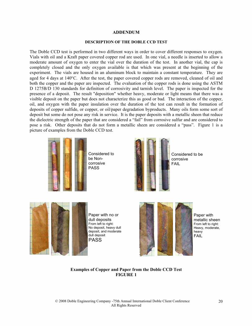
DESCRIPTION OF THE DOBLE CCD TEST The Doble CCD test is performed in two different ways in order to cover different responses to oxygen. Vials with oil and a Kraft paper covered copper rod are used. In one vial, a needle is inserted to allow a moderate amount of oxygen to enter the vial over the duration of the test. In another vial, the cap is completely closed and the only oxygen available is that which was present at the beginning of the experiment. The vials are housed in an aluminum block to maintain a constant temperature. They are aged for 4 days at 140°C. After the test, the paper covered copper rods are removed, cleaned of oil and both the copper and the paper are inspected. The evaluation of the copper rods is done using the ASTM D 1275B/D 130 standards for definition of corrosivity and tarnish level. The paper is inspected for the presence of a deposit. The result "deposition" whether heavy, moderate or light means that there was a visible deposit on the paper but does not characterize this as good or bad. The interaction of the copper, oil, and oxygen with the paper insulation over the duration of the test can result in the formation of deposits of copper sulfide, or copper, or oil/paper degradation byproducts. Many oils form some sort of deposit but some do not pose any risk in service. It is the paper deposits with a metallic sheen that reduce the dielectric strength of the paper that are considered a “fail” from corrosive sulfur and are considered to pose a risk. Other deposits that do not form a metallic sheen are considered a “pass”. Figure 1 is a picture of examples from the Doble CCD test.
Considered tobe Non-corrosivePASS
Considered to becorrosiveFAIL
Paper withmetallic sheenFrom left to right:Heavy, moderate,heavyFAIL
Paper with no ordull depositsFrom left to right:No deposit, heavy dulldeposit, and moderatedull depositPASS
Examples of Copper and Paper from the Doble CCD Test FIGURE 1