solutions to chapter 4 exercise...
TRANSCRIPT
- 1 -
Solutions to Chapter 4 Exercise Problems
Problem 4.1
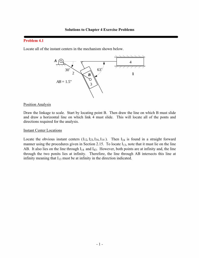
Locate all of the instant centers in the mechanism shown below.
B 12
3
A
30˚ 63˚
AB = 1.5"
4
Position Analysis
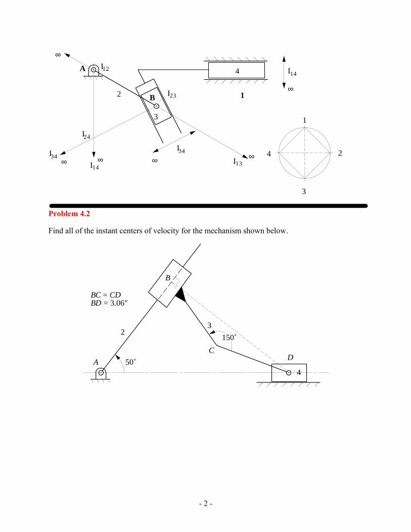
Draw the linkage to scale. Start by locating point B. Then draw the line on which B must slide and draw a horizontal line on which link 4 must slide. This will locate all of the ponts and directions required for the analysis. Instant Center Locations Locate the obvious instant centers (I12, I23, I34, I14 ). Then I24 is found in a straight forward manner using the procedures given in Section 2.15. To locate I13, note that it must lie on the line AB. It also lies on the line through I14 and I43. However, both points are at infinity and, the line through the two ponits lies at infinity. Therefore, the line through AB intersects this line at infinity meaning that I13 must be at infinity in the direction indicated.
- 2 -
B 12
3
A 4I12
I13
I14
I23
I24
I34
1
2
3
4I34
I14∞∞ ∞
∞
∞
∞
Problem 4.2
Find all of the instant centers of velocity for the mechanism shown below.
23
4A
B
CD
50˚
150˚
BC = CDBD = 3.06"

- 3 -
23
4A
B
C D50˚
I12 I34
I23
I14
I24
I13
1
2
3
4

- 4 -
Problem 4.3
In the linkage shown below, locate all of the instant centers.
2
3
4
5
6
55˚
AB = 1.35"BD = 3.9"DE = 0.9"BC = 0.9"CF = 2.0"
A
B
C
D
E
F
3.3"
\ Solution
2
3
4
5
6
A
BC
D
E
F
I12
I14
I16
I23
I34
I35
I56
I13
I24
I15
I36
I45
I25
I26
I46
35
1
26
4
Problem 4.4
Find all of the instant centers of velocity for the mechanism shown below.

- 5 -
2
4
5
3
B
C
D
E
28˚
5.0 cm
AB = 8.0 cmAC = 4.5 cmBD = 13.0 cmDE = 2.9 cm
A
2
4
5
3
B
C
D
E
A
I12
I13
I45
I34I23
I15
1
2
34
5
I14
I24
I 25
I35
Solution

- 6 -
Problem 4.5
Locate all of the instant centers in the mechanism shown below. If link 2 is turning CW at the rate of 60 rad/s, determine the linear velocity of points C and E using instant centers.
A
B
C
D
E
2
4
3
AD = 3.8"AB = 1.2"BC = 3.0"CD = 2.3"CE = 1.35"EB = 2.05"
125˚
Velocity Analysis
The two points of interest are on link 3. To find the angular velocity of link 3, use I13 and I23. Then
1vI23 =1ω2 × rI23 /I12 =1ω3 × rI23/I13
Therefore,
1ω3 = 1ω2rI23/ I12
rI23 /I13= 60 1.2
4.07 =17.7 rad / s
Because the instant center I23 lies between I12 and I13, 1ω3 is in the opposite direction of 1ω2. Therefore, 1ω3 is counterclockwise.
Then,
1vC3 =1ω3 × rC /I13 ⇒ 1vC3 = 1ω3rC /I13 =17.7 ⋅2.11 = 37.3 in / s
and
1vE3 =1ω3 × rE/I13 ⇒ 1vE3 = 1ω3rE/I13 =17.7 ⋅3.25 = 57.5 in / s
The directions for the velocity vectors are shown in the drawing.

- 7 -
B
C
E
2
4 3
D A
I 14 I12
I23
I34
I24
I13 1
2
3
4
vC3
vE3 vB3

- 8 -
Problem 4.6
Locate all of the instant centers in the mechanism shown below. If the cam (link 2) is turning CW at the rate of 900 rpm, determine the linear velocity of the follower using instant centers.
A
B2
3
70˚
R
AB = 1.5"R = 0.75"
103˚
Instant Centers

- 9 -
Velocity of the Follower
Convert the angular velocity from “rpm” to “rad/s”
12
900(2 )900 94.25 /60sec
rpm rad s CWπω = = =
At the point 23I the linear velocity of follower and cam is same.
23 2 23 2 23
1 1 1 1/ 2 /0 (94.25 / )(0.82 ) 77.285 /I A I A I A rad s in in s Downω= + = + × = =v v v r
Problem 4.7
Locate all of the instant centers in the mechanism shown below. If link 2 is turning CW at the rate of 36 rad/s, determine the linear velocity of point B4 by use of instant centers. Determine the angular velocity of link 4 in rad/s and indicate the direction. Points C and E have the same vertical coordinate, and points A and C have the same horizontal coordinate.
AB
C
D
E
23
4
5
6100˚
AB = 1.1"AC = 0.9"CD = 1.5"DE = 3.25"
Solution:
Find all instant centers and linear velocity of point B2.
1vB2 =1ω2 × rB2 /A2 ⇒ 1vB2 = 1ω2 ⋅ rB2 /A2 = 36 ⋅1.1 = 39.6 in / s
Using rotating radius method,

- 10 -
1vB4 = 32.5 in / s
To calculate the angular velocity of link 4, we can use the relations between related instant centers.
1ω2 × rI24 /I12=1ω4 × rI24 /I14
1ω4 = 1ω2 ⋅ rI24 /I12
rI24 /I14= 36 ⋅1.283
2.186 = 21.1 rad / s
Therefore,
1ω4 = 21.1 rad / s CW

- 11 -
35
1
26
4
B
C
D
E
2
45
6
I14
I34
I23
I45
I56
I16
I15
I46
I24
I36I35
I25
1vB2
1v'B2
1v I 24
1v 'I24
1v B4
13I12I
A3
I26
Problem 4.8
Using the instant-center method, find angular velocity of link 6 if link 2 is rotating at 50 rpm CCW.

- 12 -
2
3
4
5
6
20˚A
B
C
D
E
F
G (2.55", 2.95")AC = 1.2"AB = 1.35"BC = 0.9"CE = 2.7"BD = 2.6"DE = 2.6"DF = 2.2"EF = 3.1"FG = 2.8"
X
Y
Position Analysis:
Draw linkage to scale. This is a trial and error process because the linkage is a Stephenson II linkage. First draw link 2 to locate points B and C. Draw a circle centered at B of radius 2.6 ". Draw a second circle centered at C and of radius 2.7". Draw a third circle centered at G and of radius 2.8". Next construct the triangle CDF to scale and manipulate the triangle until points D, E, and F intersect their respective circles. Alternatively, the procedure given in Section 2.10 can be used.
Velocity Analysis:
The angular velocity of link 2 is
ω2 = 2 ⋅π⋅5060 = 5.24 rad / s
Using the instant centers I12, I16, and I26., we can write the relationship between ω2 and ω6 as
1ω2 × rI26/ I12 =1ω6 × rI26 /I16 (1)
Solve Eq. (1) for 1ω6
1ω6 = 1ω2 ⋅rI26 /I12
rI26 /I16= 5.24 ⋅1.56
2.35 = 3.47 rad / s
So,
1ω6 = 3.47 rad / s CW

- 13 -
35
1
26 I 16
I12
I 46
I 45
I 34
I 23
I 25
I 24
I 26
2
3
45
6
A
B
C
D
E
F
G

- 14 -
Problem 4.9
In the operation of this mechanism, link 3 strikes and trips link 5, which is initially at rest. High wear has been observed at the point of contact between links 3 and 5. As an engineer, you are asked to correct this situation. Therefore, you decide to do the following:
1) Determine the direction of the velocity of point C on link 3 at the moment of contact.
2) Relocate the ground pivot of link 4 to make the direction of the velocity of point C perpendicular to link 5 (hence less rubbing at the point of contact) when contact occurs.
Compression Spring
C
2
3
4
5
6
Driving Link
Stop
X
Y
B (0.7", 0)
A (0, 1.37")
D
E
F (0.75", -0.72")
AE = 0.79"BD = 0.69"ED = 0.74"CD = 0.59"
157˚ r = 0.125"
-10˚
Solution
Before link 3 strikes link 5, link 5 is stationary and can be considered to be fixed to the frame. Hence, link 5 is the same as link 1.
For part 1, find the location of the instant center I13. Then find the direction of the velocity of point C3 relative to the frame. This is shown in the drawing.
For part 2, we want the velocity of C3 to be perpendicular to the surface of link 5. Knowing the direction of the velocity of C3, we can find the new location of the instant center I13. Knowing the location of the instant center, we can find the new location of the ground pivot for link 4. The solution is shown in the figure.

- 15 -
C
3
4D
EA I13
Original
I13
Desired
New locationfor pivot Desired velocity
of point C
Original velocityof point C
B
B'
Problem 4.10
For the linkage given, ω2 = 1 rad/s CCW. Find I26 using the circle-diagram method. Using vA2 and I26, determine the magnitude and direction of vB6 using the rotating radius method.
52
3
4
6A
B
F (3.6", 1.45")
X
Y
AC = 1.4"AE = 3.15"DF = 1.6"BF = 1.25"BD = 0.8"
C
ED35˚
Solution:
Draw the linkage to scale. Start by locating the pivots C and F and line of motion of E. Next locate link 2 and point A. Then locate point E and draw the line AE. Next locate point D and finally E.
Find the necessary instant centers, and locate I26. Find the velocity of A2 which is given by
1vA2 =1ω2 × rA2/I12 ⇒ 1vA2 = 1ω2 ⋅ rA2 /I12 =1(1.4) = 1.4 in / s
Rotate point A onto the line defined by I12 and I16 to get A'2 and draw the velocity of A'2. From the proportionality relationship, find the velocity of I26.

- 16 -
52
3
4
6A
B
F
C
ED
I12
I16
I23
I14
I13
I26
I24
I34I35
I36
I56
∞
∞
∞
∞
1
2
3
4
5
6
A'
vA2
B'
vB6vA'2 vB'6
vI 26
1 in

- 17 -
Rotate point B onto the line defined by I12 and I16 to get B'6. From the proportionality relationship, using I26 and I16, find the velocity of B'6. This point will have the same velocity magnitude as will B6. Show the velocity vector at B6 perpendicular to BI16 . The magnitude of the velocity of B6 is given by
1vB6 = 0.563 in / s
Problem 4.11
Find the velocity of point C given that the angular velocity of gear 2 is 10 rad/s CW. B is a pin joint connecting links 4 and 5 . Point A is a pin in link 3 that engages a slot in link 4.
3
5
6C
22ω
F
E
4A
B
D (2.05", 1.3")
28˚
7˚
0.7"
0.95"
X
Y
1.0"
AE = 0.85"BD = 1.65"BC = 3.0"
Solution:
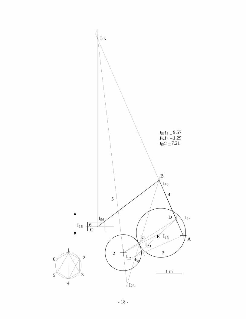
To find the velocity of point C, considered as a point in link 5, from the angular velocity of link 2 relative to link 1, the instant centers I12, I15, and I25 are needed. These may be located as shown in the figure
Then,
1ω5 =1ω2 ×(I25I12) / (I25I15) =10(1.28) / (9.57) =1.34 rad / s CW
vC5 =1ω5 ×(I15C) =1.34(7.21) = 9.66 in / s to the left.
- 18 -
5
6C
2 F
E
4
B
D
A
2
35
1
26
4
3
I23
I14
I34I12
I13
I16
I56
I45
I15
I24
I25
1 in
I25 I15 =9.57I25 I12 =1.29I15C =7.21

- 19 -
Problem 4.12
If ω2 = 5 rad/s CCW, find ω5 using instant centers.
5
43
2
ω2A
BC
D
E
F
AE = 4.1"EF = 2.0"AB = 1.5"BC = 1.55"CF = 4.0"DE = 1.0"
62˚
Solution:
Draw linkage to scale and find necessary instant centers (I12, I15, and I25 ).
The relationshp between 1ω2 and 1ω5 is
1ω2 × rI25/I12 = 1ω5 × rI25 /I15 (1)
Solve Eq. (1) for 1ω5 ,
1ω5 = 1ω2 ⋅rI25/I12
rI25 /I15= 5 ⋅ 1.83
2.27 = 4.03 rad / s
So,
1ω5 = 4.03 rad / s CW

- 20 -
4
1
2
3
5
5
4
3
2
A
B
C
D
E
F
I15
I45
I34
I12
I23
I13
I35
I25
Problem 4.13
If ω2 = 1 rad/s CCW, find the velocity of point A on link 6 using the instant center method. Show vA6 on the drawing.
26 B
ω2
5
3
4
A
F (3.6", 1.45")
X
Y
AC = BC = 1.4"BE = 3.15"DF = 1.6"
C
ED35˚
30˚

- 21 -
Solution:
26
B
5 3
4
A
F
C
ED
35
1
26
4
I16
I 12
I14
I25I36
I34
I 13
I46
I23
I 35I26
1 vD21 v 'D2
1 vI26
1 v'I26
1 vA6
Find necessary instant centers, i.e. I12, I16, and I26, and the velocity of point D as

- 22 -
1vD2 =1ω2 × rD2/F2 ⇒ 1vD2 = 1ω2 ⋅ rD2 /F2 =1 ⋅1.6 =1.6 in / s
Using rotating radius method
1vA6 = 3.095 in / s in the direction shown.
Problem 4.14
If vA2 = 10 in/s as shown, find vB4 using the instant-center method.
2
4
6
A
35
B
X
Y
C (3.35", 0.3")
D
E
AC = 1.95"AD = 2.0"DE = 1.1"BD = 0.9"BE = 1.9"
1.0"
v 2A
Solution:
Find necessary instant centers, i.e. I12, I15 and I25, then using these instant centers and the rotating radius method, find the velocity of I25 . Because the velocity is the same for all points in link 5,
1vB5 =1vB4 =1vI25 = 27.4 cm / s in the direction shown.
- 23 -
2
4
6
A
35B
1v2
CD
E I12
I23
I34
I46
I45
I16
I15
I14
I24
35
1
26
4
I25
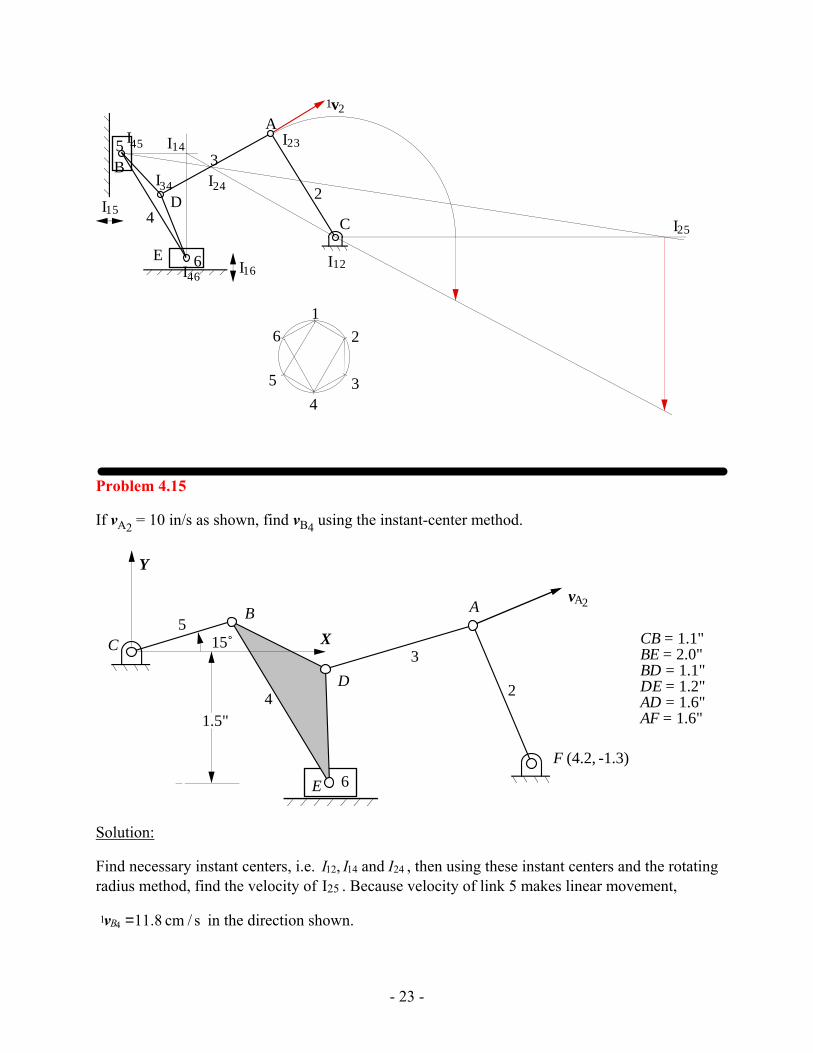
Problem 4.15
If vA2 = 10 in/s as shown, find vB4 using the instant-center method.
v 2
6
2
3
4
5AB
A
X
Y
D
C
E
F (4.2, -1.3)
15˚ CB = 1.1"BE = 2.0"BD = 1.1"DE = 1.2"AD = 1.6"AF = 1.6"1.5"
Solution:
Find necessary instant centers, i.e. I12, I14 and I24 , then using these instant centers and the rotating radius method, find the velocity of I25 . Because velocity of link 5 makes linear movement,
1vB4 =11.8 cm / s in the direction shown.

- 24 -
6
2
35
A
B1v 2A
X
Y
D
C
E
F (4.2, -1.3)
15˚
1.5"4
I 34I 23
I 45
I 12I 46
I 15
I 16
I14
35
1
26
4
I 24
1v 4B
Problem 4.16
If vA6 = 10 in/s as shown, determine the velocity vector (direction and magnitude) for point B on link 3 using the instant-center method.
2
3
4
5
6vA 6
B
A
57˚
CD = 0.8"CA = 0.6"ED = 1.85"EF = FG = 1.35"GH = 1.5"HI = 0.95"CI = 2.1"CF = 0.65"
C
D
E
F
G
H
I
Solution:
Find necessary instant centers, i.e. I13, I16, and I36 . Using rotating radius method as shown in the figure above,
1vB3 = 17.5in / s in the direction shown.

- 25 -
2
34
5
61vA6
B
A
C
D
E
F
G
H
I
I12
I 16
I14
I45I 56
I 34
I 23
I13
I 46
35
1
26
4
I 36
Problem 4.17
In the mechanism below, ω2 is 20 rad/s CCW. Find I26 and use it to find the angular velocity of link 6.
A
D
C
B
E
F
2
3
4
5 6
65˚
XY
AB = 1.5"BC = 4.9"CE = 4.3"EF = 1.2"(X , Y ) = (0.95, -4.45)D D
(X , Y ) = (2.5, -4.85)F F
- 26 -
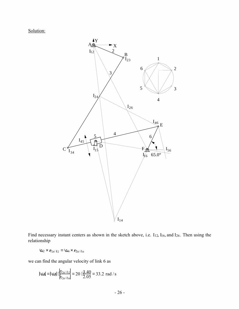
Solution:
35
1
26
4
A
DC
B
E
F
2
3
45 6
XY
65.0°
I12
I23
I34
I46
I16
I45
I15 I56
I14
I24
I26
Find necessary instant centers as shown in the sketch above, i.e. I12, I16, and I26. Then using the relationship
1ω2 × rI26/ I12 =1ω6 × rI26 /I16
we can find the angular velocity of link 6 as
1ω6 = 1ω2 ⋅rI26 /I12
rI26 /I16= 20 ⋅ 3.40
2.05 = 33.2 rad / s

- 27 -
Because I26 is between I12 and I16,
1ω6 = 33.1 rad / s CW
Problem 4.18
If vB2 = 10 in/s as shown, determine the velocity vector (direction and magnitude) of point C4 using the instant center method.
2
34
5
6A
C
D
B E
F (4.7, 0.75)
AB = 0.75"BE = 3.4"EF = 1.6"FD = 2.85"CD = 1.35"
50˚X
Y
v 2B
Solution:
Find the necessary instant centers, i.e. I12, I14 and I24 . Using rotating radius method as shown in the figure below,
1vC4 = 26 in / s

- 28 -
35
1
26
4
2
34
5
6A
C
D
BE
F
I12
I16
I36
I56
I45I34I23
I26
I46
I24
I14

- 29 -
Problem 4.19
If the velocity of A2 is 10 in/s to the right, find ω6 using instant centers.
AB = 1.75"BC = 1"BD = 3"ED = 2.25"CE = 1.45"
2
34
56
AC
D
B
E vA2
98˚
Solution:
Find necessary instant centers as shown in the sketch above, i.e. I12, I16, and I26. All points in link 2 have the same velocity; therefore,
1vA2 =1v'A2 =1vI26
Using the rotating radius method,
1vD6 =1vD6 /E6 = 13.2 in / s
Now,
1vD6 /E6 =1ω6 × rD6/E6 ⇒1ω6 =1vD6/E6
rD6/E6= 13.2
2.25 = 5.87rad / s
Therefore,
1ω6 = 5.87 rad / s CW

- 30 -
2
34
56
AC
D
B
E vA2 I12
I14I16
I56
I34 , I45
I23
I46
I24
35
1
26
4
I26
v 'A2
Problem 4.20
Crank 2 of the push-link mechanism shown in the figure is driven at ω2 =60 rad/s (CW). Find the velocity of points B and C and the angular velocity of links 3 and 4 using the instant center method.
Y
XO2 O4
A
DC
B
2
3 4
30˚
O2 A = 15 cm AD
=14.75 cm
O4 B = 30.1 cm DC
= 7.5 cm
AB
= 29.5 cm O2 O4 = 7.5 cm
Solution:
Find all instant centers and velocity of point A
1vA2 =1ω2 × rA2/O2 ⇒1vA2 = 1ω2 × rA2 /O2 = 60 ⋅0.015 = 0.9 m / s
Using rotating radius method,
1vB3 = 1.15 m / s

- 31 -
1vC3 = 0.464 m / s
Now, using the relations between instant centers distances and angular velocities, we can find the angular velocities as,
1ω2 × rI23/I12 =1ω3 × rI23/I13 ⇒ 1ω3 = 1ω2 ⋅ rI23/ I12rI23 /I13
= 60 ⋅ 3.034.14 = 43.9 rad / s
1ω2 × rI24 /I12 =1ω4 ×rI24 /I14 ⇒ 1ω4 = 1ω2 ⋅ rI24 / I12rI24 / I14
= 60 ⋅ 2.624.09 = 38.4 rad / s
Therefore,
1ω3 = 44.0 rad / s CW
1ω4 = 38.5 rad / s CW
O2 O4
A
DC
B
2
3
4
1
2
3
4
I 12 I 14
I34
I23
I13
I24
1 vA2
1v 'A2
1 vB3
1 vC3

- 32 -
Problem 4.21
The circular cam shown is driven at an angular velocity ω2 = 15 rad/s (CW). There is rolling contact between the cam and roller, link 3. Using the instant center method, find the angular velocity of the oscillating follower, link 4.
AB = 1.22"DE = 3.50"BC = 2.00"CD = 0.50"B2
4
3
A
C
D E (3.0", 3.0")
135˚
X
Y
Solution:
Find the necessary instant centers, i.e. I12, I14, and I24 . Using the relation among these instant centers, we can write
1ω2 ×rI24 /I12 =1ω4 × rI24 /I14
Now,
1ω4 = 1ω2 ⋅ rI24/ I12
rI24/ I14=15 ⋅ 2.08
7.46 = 4.18 rad / s
Therefore,
1ω4 = 4.18 rad / sCW

- 33 -
B2
43
A
C
D E
1
2
3
4
I12
I14
I23
I34
I24
Problem 4.22
If ω3 = 1 rad/s CCW, find the velocity of points E and F using the instant center method. Show the velocity vectors vF3 and vE4 on the figure.
AB = 1.65"BC = 0.88"CD = 0.85"AD = 2.46"CE = 1.26"DE = 1.56"BF = 1.94"
���� 1
2
34
A
E
B
C
D
F
0.48"1.01"
ω3
28˚
168˚
Solution
Find the instant centers I13, I14, and I34. These are shown on the figure below. Then,
1vF3 =1ω3 × rF /I13 ⇒ 1vF3 = 1ω3 rF/I13 =1(2.84) = 2.84 in / s
The vector is shown on the figure. To find 1ω4 , note that
1ω3 × rI34 /I13 =1ω4 × rI34 /I14
Therefore,
1ω4 = 1ω3rI34 /I13
rI34/I14=10.292
0.85 = 0.343 rad / s CW

- 34 -
Then,
1vE4 =1ω4 × rE /I14 ⇒ 1vE4 = 1ω4 rE/ I14 = 0.343(1.56) = 0.536 in / s
The direction is shown on the figure
1
2
34
A
EB
C
D
F
I12 I14
I13
I34
I23
v1F3
v1E4
Problem 4.23
In the eight-link mechanism, most of the linkage is contained in the black box and some of the instant centers are located as shown. The velocity of point B is 100 in/s in the direction shown. Compute the velocity of point D8 and determine the angular velocity of link 2.
Y
X
2ω
AB = 1.30"AE = 4.25"EC = 1.30"ED = 0.86"
65˚65˚
(3.58, -0.50)I67
23
A
CB
D7
8
E
BlackBox
I27
I52
I47vB2
I58
(1.85, -0.78)
(1.07, -0.45)
(2.46, 1.74)(0.40, 1.48)
Solution
To find the velocity of D8, we need the instant centers I12, I18, and I28. I12 and I18 are determined by inspection. I28 can be found using I12 and I18 and I52 and I58 . The velocity of D8 can then be found by the rotating radius method. The result is
1vD8 = 59.7 in / s
in the direction shown.

- 35 -
23
A
CB
D7
8
E
BlackBox
I27
I52
I37vB21
I23 I78
I18
I12
I58
B' I28 D'
vB'21
vD'81
vI281
vD81
Problem 4.24
If the velocity of point A on link 2 is 10 in/s as shown, use the instant center method to find the velocity of point C on link 5.
2
3
4
6
A5C
B
5
vA
D E
F (3.15", 1.9")
G
5
X
Y
75˚
DE = 2.5"AD = 0.75"AB = 1.75"BE = 1.5"GF = 1.5"
0.45"
0.25"
Solution:
Find necessary instant centers, i.e. I12, I15 and I25.
Using rotating radius method, we find the velocity of point C5 as shown below.
1vC5 =11.15 in / sec

- 36 -
2
3
4
6
A5C
B
5
DE
F
G
5
I12
I 16
I14
I23
I34
I45
I56
I15
I24
I25
1 vC5
35
1
26
4
1vA2
1 v'A21 vI25
1v 'I25
Problem 4.25
Assume that link 7 rolls on link 3 without slipping, and find the following instant centers: I13, I15, and I27. For the given value for ω2, find ω7 using instant centers.
ω2 = 2 rad/s
2
34
5
6
7
X
Y
A
BC
D
E
G
F (-2.0", 0.95")
AB = 1.8"BG = 0.85"GF = 1.7"BD = 3.9"DE = 3.25"AE = 2.0"
1.0"0.75"
90˚
Solution:
Draw linkage to scale (shown below) and find necessary instant centers, i.e. I13, I15, I27, I12 and I17.

- 37 -
Having the relationship between 1ω2 and 1ω7 using instant centers, we can write,
1ω2 ×rI27 /I12=1ω7 × rI27 /I17 (1)
Solve Eq. (1) for 1ω7,
1ω7 = 1ω2 = ⋅rI27 / I12rI27 / I17
= 2 ⋅ 3.1991.002 = 6.385 rad / s
So
1ω7 = 6.385 rad / s CW
2
3
4
5
6
7
A
B
C
D
E
G
FI14
I12
I16
I56
I57
I37
I23 I25I34
I13
I15
I17
1
2
3
45
6
7
I27

- 38 -
Problem 4.26
If vA2 = 10 in/s as shown, find vC5 using the instant-center method.
24
A3 5
B
v 2
6C
A
D
E
F
GDA = 0.95"DF = 2.45"AB = 1.45"BF = 1.8"
BE = 0.85"EG = 2.2"EC = 1.2"CG = 1.25"
1.9"
70˚
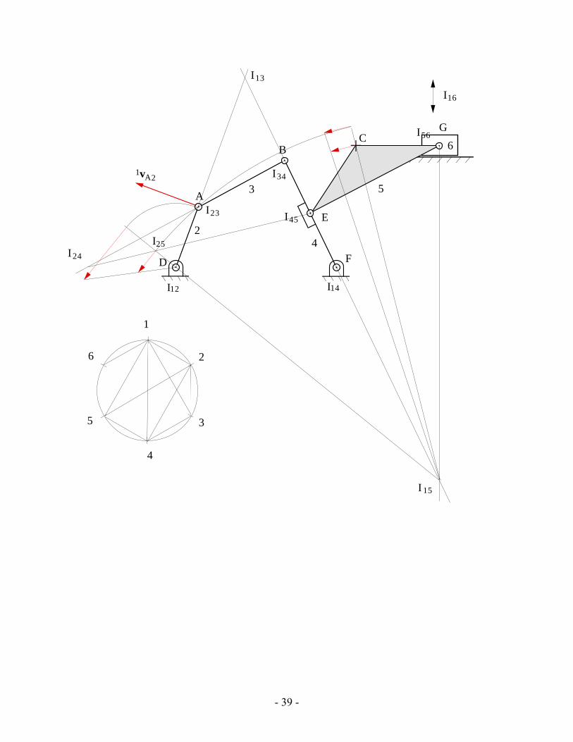
Solution:
Find necessary instant centers, i.e. I12, I15, and I25 . Using rotating radius method, get the velocity of point C5 as
1vC5 = 3.81cm / sec
- 39 -
24
A3 5
B
1v 2
6C
A
D
E
F
G
35
1
26
I12
I16
I14
4
I23
I34
I45
I56
I13
I24
I 15
I25

- 40 -
Problem 4.27
If ω2 = 10 rad/s CCW, find the velocity of point B using the instant-center method. Show the velocity vector vB3 on the figure.
1ω2
ΑΒ
2
3 4
E
C D45˚
18˚
110˚
CA = 1.5"DE = 2.5"CD = 4.0"AB = 1.6"
Solution:
Find necessary instant centers, i.e. I12, I13, and I23 .and velocity of point A as,
1vA2=1ω2 × rA2/ C2 ⇒1vA2 = 1ω2 ⋅ rA2/C2 =10 ⋅1.5 =15in / sec
Then, using rotating radius method,
1vB3 = 9.5 in / sec in the direction shown.

- 41 -
ΑΒ
2
3 4
E
C D
I12 I14
I23
I34
1
2
3
4
I13
1vA2
1v'A2
1 vB3
Problem 4.28
If ω2 = 100 rad/s CCW, find the velocity of point E using the instant center method. Show the velocity vector vE4 on the figure.
A
C
AB = 1.0"BC = 1.75"CD = 2.0"DE = 0.8"AD = 3.0"
ω2
B
D
E
70˚2
3
4
Solution:
Find necessary instant centers, i.e. I12, I14, and I24 and velocity of point B as
1vB2 =1ω2 × rB2 /A2 ⇒ 1vB2 = 1ω2 ⋅ rB2 /A2 =100 ⋅1 =100 in / sec
Therefore, using rotating radius method,
1vE4 = 27.78 in / s in the direction shown.

- 42 -
A
C
B
DI12I14
I23
I34
1vB2
1 v 'B2
1 v I24
I24 B'
E
1vE4
Problem 4.29
If ω2 = 5 rad/s CCW, find ω6 using instant centers.
C
DE
2
ω2
4
5
6
50˚
A
B
F
AC = 1.0"AB = 2.0"BD = 4.0"DE = 1.5"EF = 1.5"AF = 4.1"
3
Solution:
Find necessary instant centers as shown in the sketch above, i.e. I12, I16, and I26. Then using the relationship
1ω2 ×rI26 /I12=1ω6 × rI26 / I16
we can find the angular velocity of link 6 as
1ω6 = 1ω2 ⋅ rI26 /I12rI26 /I16
= 5 ⋅1.96951.9486 = 5.054 rad / sec
Because I26 is between I12 and I16,

- 43 -
1ω6 = 5.054 rad / sec CW
C
DE
2
4
5
6
A
B
F
3
I16
I12
I14
I56
I 45
I23
I34I24
I46
I26
35
1
26
4
Problem 4.30
If ω2 = 100 rad/s CCW, find vB4 using instant centers and the rotating radius method.
A
B
2
3
4
C
D
4
95˚
G
EF
AD = 1.8"CD = 0.75"AE = 0.7"CF = 0.45"FG = 1.75"CB = 1.0"DB = 1.65"
125˚
Solution:

- 44 -
Find necessary instant centers, i.e. I12, I14, and I24 and the velocity of I24 as
1vI24 =1ω2 × rI24 /I12 ⇒ 1vI24 = 1ω2 ⋅ rI24 / I12 =100 ⋅ 2.885 = 288.5 in / s
Using rotating radius method,
1vB4 = 460 in / s
A
B
2
3
4C
D
4
G
EF
1
2
3
4
I12 I14
I34
I23
I24
1vI24
1v 'I24
1 vB4
Problem 4.31
If vA2 = 10 in/s as shown, find the angular velocity (ω6) of link 6 using the instant-center method.
23
4
56
A
v2A
27˚
AB = 1.0"AD = 2.0"AC = 0.95"CE = 2.0"EF = 1.25"BF = 3.85"
BC
D
E
F
Solution:
Find necessary instant centers, i.e. I12, I16, and I26 and using rotating radius method,
1vE6 = 2.65 in / sec

- 45 -
or
1vE6 =1ω6 × rE/ F ⇒ 1ω6 =1vE6rE /F
= 2.652 =1.325 rad / s CCW
23
4
56A
1v 2A
B
C
D
E
F
I12 I16
I14
I56
I35I23
I34
I13
I36
35
1
26
4
I26
1 vA2'1 vI26
1v I26'
1vE6

- 46 -
Problem 4.32
If ω2 = 50 rad/s CCW, find the velocity of point G using the instant center method. Show the velocity vector vG5 on the figure.
AB = 1.16"BC = 0.70"CD = 1.45"DE = 1.16"AD = 1.30"DF = 1.30EG = 2.20"
ω2
A
C
B
D F
75˚2
3
4
G
E
32˚ 5
6
Solution:
Find the necessary instant centers, i.e. I12, I15, and I25. Using rotating radius method,
1vG5 = 33in / sec
A
C
B
DF
2
3
4
G
E5
6
I12
I16
I14
I23
I34
I56
I45
I24
I1535
1
26
4
I25
1 vB2
1 v 'B2
1 vI25
1v 'I25
1vG5

- 47 -
Problem 4.33
If ω2 = 100 rad/s CCW, find ω6.
2
34
A
C
E (2.0", 6.0")
Y
BD
F
X
5
6
2ω
AB = 1.2"BC = 6.0"CD = 3.0"AD = 4.0"BF = 3.0"
Solution:
Find necessary instant centers, i.e. I12, I16, and I26.
1ω2 ×rI26 /I12 =1ω6 ×rI26 / I16
1ω6 = 1ω2 ⋅ rI26 / I12rI26 / I16
=100 ⋅ 5.9880.337 =1777 rad / sec
Because I26 is between I12 and I16,
1ω6 =1777 rad / s CW

- 48 -
2
34
A
C
E
BD
F
5
6
I12
I 16
I14
I34
I23
I56
I 35
I13
I36I26
35
1
26
4