solutions for chapter 1 exercises - cin.ufpe.brdcfq/hardware/computer.organization.and.design... ·...
TRANSCRIPT

Solution* for Chapter 1 Exercise*
Solutions for Chapter 1 Exercises
1.1 5, CPU
1.2 1, abstraction
1.3 3, bit
1.4 8, computer family
1.5 19, memory
1.6 10, datapath
1.7 9, control
1.8 11, desktop (personal computer)
1.9 15, embedded system
1.10 22, server
1.11 18, LAN
1.12 27, WAN
1.13 23, supercomputer
1.14 14, DRAM
1.15 13, defect
1.16 6, chip
1.17 24, transistor
1.18 12, DVD
1.19 28, yield
1.20 2, assembler
1.21 20, operating system
1.22 7, compiler
1.23 25, VLSI
1.24 16, instruction
1.25 4, cache •
1.26 17, instruction set architecture

Solutions for Chapter 1 Exercises
1.27 21, semiconductor
1.28 26, wafer
1.29 i
1.30 b
1.31 e
1.32 i
1.33 h
1.34 d
1.35 f
1.36 b
1.37 c
1.38 f
1.39 d
1.40 a
1.41 c
1.42 i
1.43 e
1.44 g
1.45 a
1.46 Magnetic disk:
Time for 1/2 revolution =1/2 rev x 1/7200 minutes/rev X 60 seconds/minutes3 4.17 ms
Time for 1/2 revolution = 1/2 rev x 1/10,000 minutes/rev X 60 seconds/minutes = 3 ms
Bytes on center circle = 1.35 MB/seconds X 1/1600 minutes/rev x 60seconds/minutes = 50.6 KB
Bytes on outside circle = 1.35 MB/seconds X 1/570 minutes/rev X 60seconds/minutes = 142.1 KB
1.48 Total requests bandwidth = 30 requests/sec X 512 Kbit/request = 15,360Kbit/sec < 100 Mbit/sec. Therefore, a 100 Mbit Ethernet link will be sufficient.

Solution* for Chapter X Exarclsm
1.49 Possible solutions:
Ethernet, IEEE 802.3, twisted pair cable, 10/100 Mbit
Wireless Ethernet, IEEE 802.1 lb, no medium, 11 Mbit
Dialup, phone lines, 56 Kbps
ADSL, phone lines, 1.5 Mbps
Cable modem, cable, 2 Mbps
1.50
a. Propagation delay = mis sec
Transmission time = LIR sec
End-to-end delay =m/s+L/R
b. End-to-end delay =mls+ LJR+t
c. End-to-end delay = mis + 2I/R + f/2
1.51 Cost per die = Cost per wafer/(Dies per wafer x Yield) = 6000/( 1500 x 50%)= 8
Cost per chip = (Cost per die + Cost_packaging + Cost_testing)/Test yield =
(8 + 10)/90% = 20
Price = Cost per chip x (1 + 40%) - 28
If we need to sell n chips, then 500,000 + 20« = 28», n = 62,500.
1.52 CISCtime = P x 8 r = 8 P r n s
RISC time = 2Px 2T= 4 PTns
RISC time = CISC time/2, so the RISC architecture has better performance.
1.53 Using a Hub:
Bandwidth that the other four computers consume = 2 Mbps x 4 = 8 Mbps
Bandwidth left for you = 10 - 8 = 2 Mbps
Time needed = (10 MB x 8 bits/byte) / 2 Mbps = 40 seconds
Using a Switch:
Bandwidth that the other four computers consume = 2 Mbps x 4 = 8 Mbps
Bandwidth left for you = 10 Mbps. The communication between the othercomputers will not disturb you!
Time needed = (10 MB x 8 bits/byte)/10 Mbps = 8 seconds
Solutions for Chapter 1 EXWCIMS
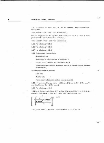
1.54 To calculate d = ax fc -axc , the CPU will perform 2 multiplications and 1subtraction.
Time needed = 1 0 x 2 + 1 x 1 = 2 1 nanoseconds.
We can simply rewrite the equation &sd = axb-axc= ax (b-c). Then 1 multi-plication and 1 subtraction will be performed.
Time needed =10x1 + 1x1 = 11 nanoseconds.
1.55 No solution provided.
1.56 No solution provided.
1.57 No solution provided.
1.68 Performance characteristics:
Network address
Bandwidth (how fast can data be transferred?)
Latency (time between a request/response pair)
Max transmission unit (the maximum number of data that can be transmit-ted in one shot)
Functions the interface provides:
Send data
Receive data
Status report (whether the cable is connected, etc?)
1.69 We can write Dies per wafer = /((Die area)"1) and Yield = /((Die area)"2)and thus Cost per die = /((Die area)3).
1.60 No solution provided.
1.61 From the caption in Figure 1.15, we have 165 dies at 100% yield. If the defectdensity is 1 per square centimeter, then the yield is approximated by
1
1 +
= .198.
Thus, 165 x .198 = 32 dies with a cost of $1000/32 = $31.25 per die.

Solution* for Chapter 1 Exercises
1.62 Defects per area.
1 Yield = 1(1 + Defects per area x Die area/2)2
Defects per area = —: j —L ••— - 1 |
1980
1992
1992 + 19S0
Die ares
YieldDefect densityDie area
YieldDefect densityimprovement
0.16
0.485.540.970.480.91
6.09

Solutions for Chapter 2 ExardsM
Solutions for Chapter 2 Exercises
2.2 By lookup using the table in Figure 2.5 on page 62,
7ffififfohoi = 0111 1111 1111 1111 1111 1111 1
= 2,147,483,642^.
2.3 By lookup using the table in Figure 2.5 on page 62,
1100 1010 1111 1110 1111 1010 1100 111<U, = ca
2.4 Since MIPS includes add immediate and since immediates can be positive ornegative, subtract immediate would be redundant.
2.6
s l l $tO, $ t3 , 9 # s h i f t $t3 l e f t by 9, store in $tOsr l $tO, t tO , 15 # s h i f t $tO r i gh t by 15
2.8 One way to implement the code in MIPS:
s l l tsO, $ s l , 11 # s h i f t receiver l e f t by 22, store in datas r l $sO, $so, 24 # s h i f t data r i gh t by 24 (data - rece iver , randi $ s l , $ s l , Oxfffe # recei ver . ready - 0:on* $sl , t s l , 0x0002 # recei ver.enabl e - 1;
Another way:
srl $sO. $sl, 2 ii data = recei ver. recei vedByteandi $sO, $sO, OxOOffandi $sl . $sl . Oxfffe it recei ver. ready - 0;or i $s l , Ssl, 0x0002 it receiver.enable = 1;
1b tsO, 0($sl) # load the lower 8 bytes of a into bitss l l $t0, JsO, 8 it $t0 - bits << 8or $s0, $s0, $tO # b i ts .data l = bits.dataOIu1 $sO, 0000 0000 OHO 0100 # b i t s .da ta? - ' d 'l u i $ t0 , 0000 0001 0000 0000 # load a 1 in to the upper b i t s of $t0or $s0. $s0, $t0 # b i t s . v a l i d - 1

Solutions for Chapttr 2
LO:
LI:
L2:
L3:
Exit
2.11
sitbne
sitbeq
slladd
lw
jradd
St3Jt3
St3$t3
Jtl$tl
«to,$to$sO
j Exitadd $sO
i Exit
sub $sO
3 Exitsub $S0
i Exit
. Ss5,
. $zero, $s5,
, $zero, Ss5,
, «tl.0($tl)
.• fs3.
. fsl,
. tsl,
. fs3,
$zero, Exit$t2
, Exit2
It4
$s4
$S2
Js2
$s4
#tit§tttt#t1fftf
test k < 0if so, exit
test k < 4if not, exit
$tl - 4*k$tl - SJumpTabletk)
$tO - JumpTable[k]jump register
k — 0breakk — 1
breakk — 2
break
k — 3break
if (k—0) f - i + j;else if (k—1) f - g + h;else if (k—2) f - g - h;else if (k—3) f - i - j:

Solutions for ChapUr 2 EJMKIMS
bne $s5, $0, Cl # branch k != 0add JsO, $s3, $s4 # f - 1 + jj Exit # break
Cl: addi $tO, $s5, -1 # $tO - k - 1bne StO, tO. C2 # branch k !- 1add tsO. $sl. $s2 # f - g + hj Exit # break
C2: addi $tO, $s5, -I # $tO - k - 2bne $tO, $0, C3 # branch k != 2sub tsO, tsl, Ss2 # f - g - hj Exit # break
C3: addi StO, $s5, -3 # $tO - k - 3bne $tO, $0, Exit \\ branch k != 3sub $sO, $s3, $s4 # f - 1 - j
Exit:
c The MIPS code from the previous problem would yield the followingresults:
(5 arithmetic) 1.0 + (1 data transfer) 1.4 + (2 conditional branch) 1.7+ (2 jump) 1.2 = 12.2 cycles
while the MIPS code from this problem would yield the following:
(4 arithmetic) 1.0 + (0 data transfer)1.4 + (4 conditional branch) 1.7+ (0jump)1.2 = 10.8 cycles
2.12 The technique of using jump tables produces MIPS code that is independentof N, and always takes the following number of cycles:
(5 arithmetic) 1.0 + (1 data transfer) 1.4 + (2 conditional branch) 1.7+ (2 jump) 1.2= 12.2 cycles
However, using chained conditional jumps takes the following number of cycles ina worst-case scenario:
(Narithmetic)1.0+ (0datatransfer)1.4 +{Nconditionalbranch)1.7+ (0jump)1.2 = 2.7Ncycles
Hence, jump tables are faster for the following condition:
N> 12.2/2.7 = 5 case statements

Solution* for Chapter 2 EXMCIMS
J
For
1 = 0
K l ?
H l
»•»•!
1- • 1
' " " , E *

Solution* for Chapter 2 ExardsM
2.16 Hence, the results from using if-else statements are better.
set_array:
loop:
compare:
add!swswswaddi
addaddislladdaddaddJalswaddibne
IwIwlwaddijr
addiswswaddi
$sp,»fp.$ra,*aO,Jfp,
$SO.$to,$tl.$t2,«aO,tal,
$sp. -5248<$sp)44(tsp)40($sp)$sp, 48
$zero, $ze$zero, 10$sO, 2Jsp, $tl$a0, $zero$s0, $zero
compare$V0.$sO,$sO,
$aO,Sra,$fp.$sp.(ra
tsp.(fp,Jra,tfp.
0($t2)ISO, 1$t0, loop
40($sp)44($sp)48($sp)$sp, 52
Jsp, "84(Ssp)0($sp)$sp, 4
jal subsit $vO, $vO, $zeroslti $v0, $v0, 1
lw $ra, 0($sp)lw $fp, 4($sp)addi $sp, $sp, 8jr $ra
# move stack pointer# save frame pointer# save return address# save parameter (num)# establish frame pointer
# 1 - 0# max iterations is 10# $tl - i * 4# $t2 - address of array[i]# pass num as parameter# pass i as parameter# cal 1 comparedium, i)# array[i] - compare(num, i);
# loop if K 1 0
# restore parameter (num)# restore return address# restore frame pointer# restore stack pointer# return
# move stack pointer# save frame pointerit save return address# establish frame pointer
# can jump directly to sub# if sub(a.b) >= 0, return 1
# restore return address# restore frame pointer# restore stack pointer# return
sub $v0, $a0, $aljr $ra
# return a-b# return

Sohitlofw for Chapter 2 ExorelM*
The following is a diagram of the status of the stack:
Before set_array
Sip 1
$sp ,
Sfp .
$
During set_array
$fpSra
SaO • num
arraypiarrays«rray[7)
array[6]
array[5]
airayM
arraylSl
arrayT^J
array[1J
array(O]
Sfp 1
During compare/sub
$fpSra
SaO * numarrayPlarraylSlarrayrj]
arrayie)array(51array(4]arrayPIarraypiarray[i]
arrayJOlJ(p$ra
2.16
# Description: Computes the Fibonacci function using a recursive process.# Function: F(n) = 0 . if n - 0;t 1. if n - 1;# F(n-l) + F(n-2). otherwise.# Input: n. which must be a nonnegative integer.# Output: F(n).ii Preconditions: none# Instructions: Load and run the program in SPIM, and answer the prompt.

Solution* for Chaptw 2 IxtidMt
if Algorithm for main program:# print promptif call fib(read) and print result.# Register usage:if taO - n (passed directly to fib)# $sl - f(n)
.data
.align 2if Data for prompts and output descriptionprmptl: .asciiz "\n\nThis program computes the Fibonacci function.prmpt2: .asciiz "\nEnter value for n: "descr: .asciiz "fib(n) - "
.text
.align 2• -globl start
_start:if Print the prompts
li $vO, 4 if p r in t_s t r system service . . .la $aO, prmptl # . . . passing address of f i r s t promptsyscal1li SvO, 4 # pr in t_st r system service . . .la $aO, prmpt2 if . . . passing address of 2nd promptsyscal1
if Read n and cal l f i b with resultli $vO, 5 if read_int system servicesyscallmove $aO, $vOj a l f i bmove $s l , $vO
# Print resultli $vO, 4la $aO, descrsyscallli $vO, 1move $aO, $slsyscall
if Call system - exitli $vO. 10syscal1
if Algorithm for Fib(n):it if (n == 0) return 0if else if (n — 1) return 1# e l s e r e t u r n f i b ( n - l ) + f 1 b ( n - 2 ) .it
if $aO - n = result of read§ ca l l f ib (n )if $sl = f ib (n)
if pr in t_st r system service . . .it . . . passing address of output descriptor
if p r in t_ in t system service . . .it . . . passing argument f ib (n)

Solution* for Chapter 2 Exordsu
# Register usage:# $aO - n (argument)# $tl - fibCn-1)# $t2 - fibCn-2)# $vO = 1 (for comparison)## Stack usage:# 1. push return address, n, before calling fib(n-l)# 2. pop n# 3. push n, fib(n-l), before calling fibtn-2)# 4. pop fib(n-l), n, return address
fib: bne $aO, $zero, fibneO # if n ~ 0 ...move $vO, $zero # ... return 0jr $31
fibneO: # Assert: n !- 0li tvO, 1bne $aO, $vO, fibnel # if n — 1 ...jr $31 # ... return 1
fibnel: # Assert: n > 1## Compute fib(n-l)
addi $sp, $sp, -8 # push ...sw $ra, 4($sp) # ... return addresssw $aO, O($sp) # ... and naddi $aO, $aO, -1 # pass argument n-1 ...jal fib # ... to fibmove $tl, $vO # $tl = fib(n-l)lw $aO, O($sp) # pop naddi $sp, $sp, 4 # ... from stack
## Compute fib(n-2)addi $sp, $sp, -8 tf push ...sw $aO, 4($sp) # ... nsw $tl, 0($sp) # ... and fib(n-l)addi $aO, $aO, -2 # pass argument n-2 ...jal fib # ... to fibmove $t2, $vO # tt2 = fib(n~2)lw $tl, OC$sp) # pop fib(n-l) ...Iw $aO, 4{$sp) # ... nlw $ra, 8{$sp) # ... and return addressaddi $sp, $sp, 12 # ... from stack
## Return fib(n-l) + ffbCn-2)add $vO, $tl. $t2 # $vO - fib(n) = fib(n-l) + fib(n-2)jr $31 # return to caller

SoluUom for Chaptar 2 ExarclM*
2.17
# Description: Computes the Fibonacci function using anit iterative process.# Function: F(n) = 0 , if n = 0;# 1, 1f n - 1;# F(n-l) + Ftn-2). otherwise.it Input: n, which must be a nonnegative integer.it Output: F(n).# Preconditions: none# Instructions: Load and run the program in SPIH, and answerit the prompt.it# Algorithm for main program:it print promptit call f i b ( l , 0, read) and print result.it# Register usage:# $a2 - n (passed directly to f ib)it $sl - fCn)
.data
.align 2# Data for prompts and output descriptionprmptl: .asciiz "\n\nThis program computes the the
Fibonacci functi on."prmpt2: .asciiz "\nEnter value for n: "descr: .asciiz "fib{n) - "
.text
.align 2
.globi start—start:it Print the prompts
li $vo, 41 a $aO, prmptl
# Read n and ca
syscal1li $vo, 4la $aO, prmpt2prompt syscall1 fib with resultli $vO, 5syscal1move $a2, $vOli $al, 0li $aO, 1jal fibmove Isl, IvO
# print_str system service ...# ... passing address of firstprompt
# print_str system service ...# ... passing address of 2nd
# read_int system service
# $a2 - n - result of read# Sal - fib(O)it $aO - fibtl)it call fib(n)it $sl - fib(n)

Sohrthms for Chapter 2 Exercises
it Print result11 JvO, 4la iaO, descr
syscal1If $vO, 1move $aO, ts1syscal1
# Call system - exitli $vO. 10syscal1
# Algor i thm for FibCa. b, count) :# if (count — 0) re turn b# else re turn f i b ( a + b, a, count - 1)itit Register usage:it $a0 - a - f ib(n- l )it Sal - b - fib{n-2)it $a2 - count (initially n, finally 0 ) .it ttl = temporary a + b
it print_str system service ...it ... passing address of outputit descriptor
it print_int system service ...it ... passing argument fib(n)
fib: bne $a2, $zero. fibneOmove $vO, $aljr $31
addi $a2, $a2, -1add $tl, $aO, $aimove $al, taOmove $aO, ttlj fib
# if count — 0 ...# ... return b
# Assert: n !- 0# count - count - 1# $tl - a + bit b = a# a - a + old bit tail call fib(a+b.
2.18 No solution provided.
2.19 Irisin ASCII: 73 114 105 115
Iris in Unicode: 0049 0072 0069 0073
Julie in ASCII: 74 117 108 105 101
Julie in Unicode: 004A 0075 006C 0069 0065
2.20 Figure 2.21 shows decimal values corresponding to ACSII characters.
A
65 32
b
98
y
121
t
116
e
101 32
i
101
s
115 32
8
56 32
b
98
i
101
t
116
s
115 0

Solution* for Chapttr 2 Exwdm
# initialize running sum StO - 0# finished when Sal is 0# compute running sum of $aO# compute this $al times
4 add 100 to a * b# return a * b + 100
# max i- 2500 * 4# max j- 2500 * 4# tvO - 0# 1 - 0# $t4 = address of array l[i] -# $t4 - array l[i]# j - 0# $t3 - address of array 2[J]# $t3 - array 2[J]# if (array l[i] !- array 2[j]) skip $v0+# $v0++# j++# loop if j I- 2500 * 4# i++# loop 1f 1 !- 2500 * 4
The code determines the number of matching elements between the two arraysand returns this number in register $v0.
2 .31 Ignoring the four instructions before the loops, we see that the outer loop(which iterates 2500 times) has three instructions before the inner loop and twoafter. The cycles needed to execute these are 1 + 2 + 1 = 4 cycles and 1 + 2 = 3cycles, for a total of 7 cycles per iteration, or 2500 x 7 cycles. The inner loop ,requires 1 + 2 + 2 + 1 + 1 + 2 = 9 cycles per iteration and it repeats 2500 x 2500times, for a total of 9 x 2500 x 2500 cycles. The total number of cycles executed istherefore (2500 x 7) + (9 x 2500 x 2500) = 56,267,500. The overall execution timeis therefore (56,267,500) / (2 x 10⁹) = 28 ms. Note that the execution time for theinner loop is really the only code of significance.
1 oop:
finish:
beqaddsubjaddiadd
$to,
$al.StO.$al,loop
StO.SvO,
SzerSierStO,Sal,
StO,StO,
The program computes a * b +
2.30
outer:
Inner:
skip
sllslladdaddaddlwaddaddlwbneaddiaddibneaddibne
Sa2.Sa3.SvO.StO.St4,$t4,»tl,St3.St3,»t3.SvO,Stl,
m.StO,StO.
$a2.8a3,SzeroSzeroSao,
0, finishSaO1
100Szero
100.
22, Szero. SzeroStO
0(St41SzeroSal,
. SzeroStl
0(St3)St4,SvO,Stl,Sa3,StO,Sa2.
skip14inner4outer

Solutions for Chaptor 2 EXWCIMS
2.32 ori H I , $tO. 25
2.34
# register ttl - StO I 25;
addi $vO, $zero, -1 # Initialize to avoid counting zero wordloop: lw, $vl, 0($a0) tf Read next word from source
addi $vO, $vO, 1 # Increment count words copiedsw $vl, 0($al) # Write to destinationaddi $aO, $aO, 4 # Advance pointer to next sourceaddi Sal, $al, 4 # Advance pointer to next destinationbne $vl, tzero, loop # Loop if word copied != zero
Bug I:Count($vO) is initialized to zero, no t -1 to avoid counting zero word.
Bug 2: Count (SvO) is not incremented.
Bug 3: Loops if word copied is equal to zero rather than not equal.
2.37
clear- ItO
beq t t l . small. L
beq H2. big. L
11 t t l . small
11 JtZ, big
ble t t3 . St5. L
bge t t5. t t3 . L
addi ttO. ttZ. big
lw i t5 , b1g(Jt2)
UO-0
if<*tl = small)goto L
if <tt2 ==• big) go to L
t t l * small
ttZ = big
tf <*t3 <=It5}goto L
lf{tt4>it5)gotoL
lf(tt5>=tt3)gotoL
StO = ttZ + big
tt5 = Memoryltt2 + big]
add t
beq t
11 1
beq t
addi t
lui %
on" Isit tbeq tsit t
sit 1beq I11 tadd t
add J
ero. tzero
a l l
t . L
ero. L
ero. small
per(big)
2. lower(big)
5, t t3
ero, L
5. St4
ero. L
5. tt3
ero, L
1. tat
t . %xz
2. tat
Note: In the solutions, we make use of the 1 i instruction, which should be imple-mented as shown in rows 5 and 6.
2.38 The problem is that we are using PC-relative addressing, so if that address istoo far away, we won't be able to use 16 bits to describe where it is relative to thePC. One simple solution would be

Solutions for Chapter 2 ExerciMS
here: bne $sO, $s2, skipj there
skip:
there: add $sO, $sO, $sO
This will work as long as our program does not cross the 256MB address bound-ary described in the elaboration on page 98.
2.42 Compilation times and run times will vary widely across machines, but ingeneral you should find that compilation time is greater when compiling with op-timizations and that run time is greater for programs that are compiled withoutoptimizations.
2.45 Let /be the number of instructions taken on the unmodified MIPS. This de-composes into 0.42/arithmetic instructions (24% arithmetic and 18% logical),0.361 data transfer instructions, 0.18/conditional branches, and 0.031 jumps. Us-ing the CPIs given for each instruction class, we get a total of (0.42 x 1.0 + 0.36 x1.4 + 0.18 x 1.7 + 0.03 x 1.2) x /cycles; if we call the unmodified machine's cycletime Cseconds, then the time taken on the unmodified machine is (0.42 x 1.0 +0.36 x 1.4 + 0.18 x 1.7 + 0.03 x 1.2) x /x Cseconds. Changing some fraction,/(namely 0.25) of the data transfer instructions into the autoincrement or autodec-rement version will leave the number of cycles spent on data transfer instructionsunchanged. However, each of the 0.36 x / x /data transfer instructions that arechanged corresponds to an arithmetic instruction that can be eliminated. So, thereare now only (0.42- (036 xf)) x I arithmetic instructions, and the modified ma-chine, with its cycle time of 1.1 x Cseconds, will take {(0.42 - 0.36/) x 1.0 + 0.36 x1.4 + 0.18 x 1.7 + 0.03 x 1.2) x I x 1.1 x Cseconds to execute. When/is 0.25, theunmodified machine is 2.2% faster than the modified one.
2.46 C
Loop:
ode befotInsitbnesitbeqslladdIwbneaddi
1
me:
m.sto.sto,sto.sto.Stl,
Stl.
sto,sto,Ss3,
Loop
4(Ss6)
Ss3,
Szero
Ss3.
Szero
Ss3,
Stl.
Szero
. IndexOutOfBounds
St2, IndexOutOfBounds
2$S6
8($tl)
Ss5.
Ss3,
Exit1
# temp reg $t2 - length of array save
# temp reg $tO - 1 if 1 < 0
tt if 1< 0, goto Error
# temp reg $t0 = 0 if i >= length
# if i >- length, goto Error
# temp reg $tl = 4 * i
# Stl - address of saved]
# temp reg $t0 = save[i]
# go to Exit if save[i] !* k
# i - 1 + 1

Solutions for Chaptw 2 EXWCIMS
The number of instructions executed over 10 iterations of the loop is 10 x 10 + 8 +1 = 109. This corresponds to 10 complete iterations of the loop, plus a final passthat goes to Exit from the final bne instruction, plus the initial Iw instruction.Optimizing to use at most one branch or jump in the loop in addition to usingonly at most one branch or jump for out-of-bounds checking yields:
# temp reg $t2 = length of array save
# temp reg $tO - 1 if i < 0
# temp reg $t3 - 0 if i >- length# f l i p the value of $t3# $t3 - 1 if i is out of bounds# if out of bounds, goto Error# tern reg Stl - 4 * 1# Stl - address of saved]# temp reg $tO - saved]# go to Exit if save[i] !- k# 1 - 1 + 1# temp reg $tO = 1 if i < 0# temp reg St3 = 0 if i >- length# f l i p the value of $t3# $t3 = 1 if i is out of bounds•# if out of bounds, goto Error# temp reg $tl = address of saved]# temp reg $tO = save[i]# go to Loop if save[i] = k
The number of instructions executed by this new form of the loop is 10+10*9 =100.
sitsitslti
orbnestladdInbneaddi
sitsitslti
orbneaddi
lubeq
uz.tto,
tt3,
tt3.
(t3.
tt3.
ttl.
ttl.
tto,
sto,
ts3.
tto.
tt3.
St3,
$t3.
it3,
itl.
tto.
no.
Code after:4($s6)
$S3,
$S3,
$t3,
>t3,(zero
»s3,
ttl,
tzero
$tz1
tto, IndexOutOfBounds
2ts6
8(ttl)
ts5,
*s3,
$S3,
>s3.
«t3.
tt3,tzero
ttl,
Exit
1tzero
tt21tto, IndexOutOfBounds
48($tl)
«s5. Loop

Solution* for Chapter 2 EXWCIMS
2.47 To test for loop termination, the constant 401 is needed. Assume that it isplaced in memory when the program is loaded:
Loop:
lwlwlwaddsitbnesitbeqsitbeqaddlwaddaddswaddi
sitbne
tt8,
tt7,
tt6,
tto.
$t4.
tt4.
tt4,
tt4.
$t4.
tt4,
ttl,
tt2.
$t2.
$t3.
tt2,
no,tt4.
tt4.
AddressConstant401(tzero)
4(taO)
4(tal)
tzero, tzero
ttO. tzero
tzero, IndexOutOfBounds
ttO. St6
Jzero, IndexOutOfBounds
ttO, tt7
tzero, IndexOutOfBounds
tal, StO
8(Stl)
tt2, tsO
taO. ttO
8(tt3)
ttO, 4
StO, St8
tzero, Loop
ititItititititititititititititititit
tt8 - 401
tt7 = length of a[]
St6 - length of b[]
Initialize 1 - 0
$t4 - 1 If 1 < 0
if i< 0. goto Error
tt4 - 0 If 1 >- length
if i >- length, goto Error
tt4 = 0 if i >- length
if i >- length, goto Error
ttl - address of b[i]
St2 - bti]
$t2 - b[i] + c
tt3 - address of a[i]
a[i] - b[i] + c
i - i + 4
tt8 - 1 If ttO < 401, i.e., i
goto Loop if i <= 100
The number of instructions executed is 4 + 101 X 14= 1418. The number of datareferences made is 3 + 101 X 2 = 205.
2.48compareTo: sub $v0, $a0, Sal # return v[i].value - v[j+l],value
jr $ra # return from subroutine
2.49 From Figure 2.44 on page 141, 36% of all instructions for SPEC2000int aredata access instructions. Thus, for every 100 instructions there are 36 data accesses,yielding a total of 136 memory accesses (1 to read each instruction and 36 to accessdata).
a. The percentage of all memory accesses that are for data = 36/136 = 26%.
b. Assuming two-thirds of data transfers are loads, the percentage of all mem-ory accesses that are reads = (100 + (36 x 2/3)}/136 = 91%.

Solutions for Chaptar 2
2.50 From Figure 2.44,39% of all instructions for SPEC2000fp are data access in-structions. Thus, for every 100 instructions there are 39 data accesses, yielding atotal of 139 memory accesses (1 to read each instruction and 39 to access data).
a. The percentage of all memory accesses that are for data = 39/139 = 28%.b. Assuming two-thirds of data transfers are loads, the percentage of all mem-
ory accesses that are reads = (100 + (39 x 2/3))/139 = 91%.
2.51 Effective CPI = Sum of (CPI of instruction type x Frequency of execution)
The average instruction frequencies for SPEC2000int and SPEC2000fp are 0.47arithmetic (0.36 arithmetic and 0.11 logical), 0.375 data transfer, 0.12 conditionalbranch, 0.015 jump. Thus, the effective CPI is 0.47 x 1.0 + 0.375 x 1.4 + 0.12 x 1.7+ 0.015x1.2=1.2.
2.52
load badd c
add cstore bnegadd a.store d
AcAc
AcAcAcAc
- b;+- c;
+- c:- b;-- Ace;-- b;
d - ACC;Total:
3333313322 28
Code size is 22 bytes, and memory bandwidth is 22 + 28 = 50 bytes.
push bpush cadddup
3311
400

Solution* for Chapter 2 Exarcise*
pop apush c
add
duopop bnegpush aaddpop dTotal:
3311
3
1313
27
4
004
0404
28
Code size is 27 bytes, and memory bandwidth is 27 + 28 = 55 bytes.
I add b, a, c # b-a-
Total:
7
21
12
36
Code size is 21 bytes, and memory bandwidth is 21 + 36 = 57 bytes.
load $load I
add $s tore S
add Sstore $
sub $store $Total:
1 , b
2, c3. $ 1 ,3. a
1 . 12.1 . b4, 134. d
12
$3
t l •
1
23-
-4
-
i
$
t
i +
2 +
3 -
SZ
$3;
t l :
44
34
3434
29
4404
04
04
20
Code size is 29 bytes, and memory bandwidth is 29 + 20 = 49 bytes.

Solutions for Chaptsr 2 E X W C I M *
The load-store machine has the lowest amount of data traffic. It has enough regis-ters that it only needs to read and write each memory location once. On the otherhand, since all ALU operations must be separate from loads and stores, and alloperations must specify three registers or one register and one address, the load-store has the worst code size. The memory-memory machine, on the other hand,is at the other extreme. It has the fewest instructions (though also the largest num-ber of bytes per instruction) and the largest number of data accesses.
2.53 To know the typical number of memory addresses per instruction, the na-ture of a typical instruction must be agreed upon. For the purpose of categorizingcomputers as 0-, 1-, 2-, 3-address machines, an instruction that takes two operandsand produces a result, for example, a d d, is traditionally taken as typical.
Accumulator: An add on this architecture reads one operand from memory, onefrom the accumulator, and writes the result in the accumulator. Only the locationof the operand in memory need be specified by the instruction. Category: 1-address architecture.
Memory-memory: Both operands are read from memory and the result is writtento memory, and all locations must be specified. Category: 3-address architecture.
Stack: Both operands are read (removed) from the stack (top of stack and next totop of stack), and the result is written to the stack (at the new top of stack). Alllocations are known; none need be specified. Category: 0-address architecture.
Load-store: Both operands are read from registers and the result is written to a reg-ister. Just like memory-memory, all locations must be specified; however, locationaddresses are much smaller—5 bits for a location in a typical register file versus 32bits for a location in a common memory. Category: 3-address architecture.
2.54
sbn temp, temp, .+1 # clears temp, always goes to next instructionstart: sbn temp, b, .+1 # Sets temp = -b
sbn a, temp, .+1 # Sets a - a - temp - a - {-b) - a + b
2.55 There are a number of ways to do this, but this is perhaps the most conciseand elegant:
sbn c, c, .+1 # c = 0;sbn tmp, tmp, .+1 # tmp - 0;
loop: sbn b, one, end # whi le { - -b >= 0)sbn tmp, a, loop # tmp -=•= a; /* always continue */
end: sbn c, tmp, .+1 # c = -tmp; / * - a x b * /
2.56 Without a stored program, the programmer must physically configure themachine to run the desired program. Hence, a nonstored-program machine is onewhere the machine must essentially be rewired to run the program. The problem

Solutions for Chapter 2 Exwelsas
with such a machine is that much time must be devoted to reprogramming the ma-chine if one wants to either run another program or fix bugs in the current pro-gram. The stored-program concept is important in that a programmer can quicklymodify and execute a stored program, resulting in the machine being more of ageneral-purpose computer instead of a specifically wired calculator.
2.57
MIPS:
loop:
add
addi
sll
add
Iw
add
sll
add
sw
addi
bne
PowerPC:
loop:
add
addi
1 wu
add
sll
sw
addi
bne
tto.
ttl,
$t2.
$t3,
tt4,
tt4.
$t2,
$t3,
tt4,
(to,
$to.
$to,
$tl,
tt4,
tt4,
tt2,
ft4,
tto.
tto,
tze
tze
to,
tt2
ro, $zero
ro, 10
2
, tal
0(tt3)
tt4
to,tt2
, tto
4
, taO
0(tt3)
stottl
tze
, 1
. loop
ro, tzero
tzero, 10
4(t
tt4
to,
taO
$to$tl
al)
, tto
4
+tt2
, 1
, 1 oop
ttt1ttttttt
t#
#t1#II
1 - 0
set m
tt2 -
tt3 -
tt4 -
tt4 -
tt2 -
tt3 -
a[2i]
i++
loop
i --0
set m
tt4 =
tt4 -
tt2 -
a[2i]
i++
1 oop
ax iterations of loop
i * 4
address of b[i]
b[i]
bCi] + i
1 * 4 * 2
address of a[2i]
- b[i] + 1
if i !- 10
ax iterations of loop
bti]
bti] + 1
1 * 4 * 2
- b[i] + i
if i !- 10

Solution* for Chapter 2 EJMTCIMS
add
add
addi
outer: add
1uadd
add!
inner: add
lwbne
addi
skip: addi
bne
sit
bne
add
next: addi
bne
PowerPC:
addaddaddi
addouter: lwu
addaddi
addinner: lwu
bneaddi
tvO,$to,St8,
St4,
St4,
$sO,
$tl.
St3,
$t3.
St3,
SsO,
Stl,
$tl.
*t2,
$t2,
$vO,
sto,tto,
tvO,$to,«t8,
St7,
(t4,
SsO,
Sctr
St6,
St3,
$t3.
$sO.
$zero, Szero
Szero, 400
$aO, StO
0($t4)
$zero, Szero
$zero, 400
$aO, $tl
0($t3)
St4, skip
SsO, 1
Stl, -4
Szero, inner
SsO, SvO
SsO, Szero
StO, 4
St8, outer
Szero, Szero
Szero, Szero
Szero, 400
SaO, Szero
4(St7)
Szero, Szero
, Szero, 100
SaO, Szero
4($t6)
St4, skip
SsO, 1
ttttit##f1ttttt
§11
tttttt##ttt
freq = 0
i - 0
St8 - 400
St4 - address of a[i]
St4 - a[i]
x - 0
j - 400
St3 - address of a[j]
St3 - a[j]
if (a[1] !•
X++
J--loop if j
St2 - 0 if
freq = x
i++
loop if i
freq - 0
1 - 0
St8 - 400
keep track
$t4 - a[i]
x - 0
i - 100
keep track
St3 - a[j]
if !a[i] !•
X++
• a[j]l skip x++
!- 0
x >= freq
!- 400
of a[i] with update addressing
of a[j] with update addressing
- a[j]) skip x++

Solutions for Chapter 2 Exordsos
skip: besitbneaddaddi
bne
inner
stz,
$t2.
$vO,
no.no.
, $ctr!-0
SsO, $vO$zero, next
SsO,
$to,
$t8.
$zero
4outer
# j--. loop If j!-0
t tt2 - 0 if x >- freq
# skip freq - x if
t freq - x
t 1++
# loop if 1 !- 400
xor $s0, $s0, $slxor $sl, SsO, Islxor SsO. SsO. $sl

Solutions for chapter 3 ExarclsM
Solutions for Chapter 3 Exercises3.1 0000 0000 0000 0000 0001 0000 0000 0000two
3.2 1111 1111 1111 1111 1111 1000 0000 0001two
3.3 1111 1111 1110 0001 0111 1011 1000 0000two
3.4 -250ten
3.5 -17 t t n
3.6 2147483631wn
3.7
addu $t2, Izero, $t3 # copy St3 into $t2bgez $t3, next # if $t3 >= 0 then donesub t t2 , Szero, St3 # negate $t3 and place into $t2
Next:
3.9 The problem is that A_1 ower will be sign-extended and then added to $t0.The solution is to adjust A_upper by adding 1 to it if the most significant bit ofA_l ower is a 1. As an example, consider 6-bit two's complement and the address23 = 010111. If we split it up, we notice that A_l ower is 111 and will be sign-extended to 111111 = - 1 during the arithmetic calculation. A_upper_adjusted= 011000 = 24 (we added 1 to 010 and the lower bits are all Os). The calculation isthen24+- l = 23.
3.10 Either the instruction sequence
addu $t2, $t3, $t4situ $t2, $t2. $t4
addu $t2, $t3, $t4situ $t2. -$t2, $t3
works.
3.12 To detect whether $ s 0 < $ s 1, it's tempting to subtract them and look at thesign of the result. This idea is problematic, because if the subtraction results in anoverflow, an exception would occur! To overcome this, there are two possiblemethods: You can subtract them as unsigned numbers (which never produces anexception) and then check to see whether overflow would have occurred. Thismethod is acceptable, but it is lengthy and does more work than necessary. Analternative would be to check signs. Overflow can occur if $ s 0 and (- $ s 1) share

Solutions for Chapter 3 Exordaoa
the same sign; that is, if $ s 0 and $ s 1 differ in sign. But in that case, we don't needto subtract them since the negative one is obviously the smaller! The solution inpseudocode would be
if <$s0<0) and (Ssl>0) then$tO:-l
else if <$s0>0) and {$sl<OJ then$tO:-O
else$tl:-$sO-Ssrif ($tl<0) then
$tO:-lelse
$tO:-O
3.13 Here is the equation:
Sum = (a • b • Carryln) + (a • b • Carryln) + (a • b • Carryln) + (a • b • Carryln)
Carryln

Solution* for Chapter 3 Exwdsas
00
0
1
1
1
1
0
1
1
0
0
1
1
1
0
1
0
1
0
1
NoneAdd the multiplicand
Add the multiplicand
Add twice themultiplicandSubtract twice themultiplicand
Subtract themultiplicand
Subtract themultiplicandNone
End of a string of IsA string of one 1, so subtract the multiplicand atposition i for the beginning of the string and add twicethe multiplicand (twice to align with position 1 + I) forthe end of the string; net result, add the multiplicandEnd of a string of Is; must align add with 0 In positioni + 1Beginning of a string of Is; must subtract with 1 inposition 1 +1End of string of Is, so add multiplicand, plusbeginning of a string of Is, so subtract twice themultiplicand; net result Is to subtract Hie multiplicandBeginning of a string of Is
Middle of a suing of Is
One example of 6-bit operands that run faster when Booth's algorithm looks at 3bits at a time is 21 t e n x 27^ , = 567^ .
Two-bit Booth's algorithm:
010101 =2 I t e n
X011011 = 2 7 ^
- 010101 10 string (always start with padding 0 to right of LSB)000000 11 string, middle of a string of Is, no operation
+ 010101 01 string, add multiplicand- 010101 10 string, subtract multiplicand000000 11 string
+ 010101 01 string
11111101011 two's complement with sign extension as needed0000000000 zero with sign extension shown000010101 positive multiplicand with sign extension111010110000000
(-010101
01000110111 =567 t e n

Solution* for Chapter 3 Exorcl***
Don't worry about the carry out of the MSB here; with additional sign extensionfor the addends, the sum would correctly have an extended positive sign. Now,using the 3-bit Booth's algorithm:
010101 = 2 1 t e n
X0110U = 2 7 ^
- 010101 110 string (always start with padding 0 to right of LSB)— 010101 101 string, subtract the multiplicand
+• 0101010 011 string, add twice the multiplicand (i.e., shifted left 1 place)
11111101011 two's complement of multiplicand with sign extension111101011 two's complement of multiplicand with sign extension0101010
01000110111 "S67 , , , ,
Using the 3-bit version gives only 3 addends to sum to get the product versus 6addends using the 2-bit algorithm.
Booth's algorithm can be extended to look at any number of bits b at a time. Theamounts to add or subtract include all multiples of the multiplicand from 0 to2*6"1'. Thus, for b> 3 this means adding or subtracting values that are other thanpowers of 2 multiples of the multiplicand. These values do not have a trivial"shift left by the power of2numberofbitposit ions"methodof computation.
3.25
1 A »fO, -8(»gp)1 A $f2, -ie(tgp)1 A Sf4, -24(Sgp)fmadd tfO. tfO, t f2, (f4s.d tfO, -8($gp)
3.26 a.
1 = 0100 0000 0110 0000 0000 00000010 0001
y = 0100 0000 1010 0000 0000 0000 0000 0000
Exponents
100 00000+100 0000 1
1000 0000 1-01111111

Solutions for Chapter 3 ExerclMS
X 1.100 0000 0000 0000 0010 0001y xl.010 0000 0000 0000 0000 0000
1 100 0000 0000 0000 0010 0001 000 0000 0000 0000 0000 0000+ 11 0000 0000 0000 0000 1000 010 0000 0000 0000 0000 0000
1.111 0000 0000 0000 0010 1001 010 0000 0000 0000 0000 0000
Round result for part b.
1.111 1100 0000 0000 0010 1001
Z0011 1100 111000000000 1010 11000000
Exponents
100 0001 0- 11 1100 1
100 1 --> shift 9 bits
1.1110000 0000 0000 0010 1001010 0000 00+ z 111000000000101011000000
1.111 OOOOOIUOOOOOOIO 1110 101GRS
Result:
0100 000101110000011100000100 1111
b.
1.111 1100 0000 0000 0000 1001 result from mult.+ z 1110000 0000 0101011
1.111 11000111 0000 0001 1110011GRS
0100000101110000 01110000 01001110

Solution* for Chapter 3 ExorclM*
0 0 0 0
• 0 0 0 0
0 0 0 0
0 0 0 0
0 0 0 0
0 0 0 0
0 0 0 0
0 0 0 0
0 0 0 0
0 0 0 0
0 0 0 0
0 0 0 0
1 1 1 1 1
0 1 0 1 1 0 1 1
0 0 0 0 1 1 0 1
0 0 0 0 0 0 0 0 0 0 0 0 0 0 0 0 0 0 0 0 0 0 0 0 0 1 1 0 1 0 0 0
- 0 0 0 0 0 0 0 0
0 0
0 0
0 0 0 0 0 0 0 0 0 0
0 0 0 0 0 0 0 0 0 0
0 0 0 1 0 1 1 0 1 1
0 0 0 0 0 0 1 1 0 1
0 0 0 0 0 0 0 0 0 0 0 0 0 0 0 0 0 0 0 0 0 0 0 0 0 1 0 0 1 1 1 0
0
0
0
0
n
0
0
0
0
n
0
0
0
0
n
0
o .
0
0
0
n
0
0
0
o
n
0
0
0
0
0
n
0
0
0
0
0
0
0
0
0
0
0
0
0
0
0
0
0
0
0
n
0
0
0
0
n
0
0
0
0
n
0
0
0
0
n
0
0
0
0
f>
0
0
0
0
n
0
0
0
0
0
0
0
0
0
0
0
'o0
0
0
0
0
0
0
0
0
0
0
0
0
0
0
0
0
0
0
0
0
1
0
0
1
0
0
0
1
0
0
1
1
0
1
1
1
0
0
1
0
1
0
1
0
1
1
1
1
1
1
0
1
0
1
1
0
1
1
1
1
0 0 0 0 1 1 0 1 1
-
0
0
0
0
0
0
0
0
0
0
0
0
0
0
0
0
0
0
0
0
0
0
0
0
0
0
0
0
0
0
0
0
0
0
0
0
0
0
0
0
0
0
0
0
0
0
0
0
0
0
1
0
0
1
1
1
1
0
1
0
1
1
It™
1
1
- 0 0 0 0 0 0 0 0 0 0 0 0 0 0 0 0 0 0 0 0 0 0 0 0
0 1 0 0 1 1 1
0 0 0 1 1 0 1 1
0 1 1 0 1
- 0 0 0 0 0 0 0 0 0 0 0 0 0 0 0 0 0 0 0 0 0 0 0 0 0 0 0 0 1 1 0 1

Solutions for Chapter 6 E X O K I M S
Solutions for Chapter 6 Exercises
6.1
a. Shortening the ALU operation will not affect the speedup obtained frompipelining. It would not affect the dock cycle.
b. If the ALU operation takes 25% more time, it becomes the bottleneck in thepipeline. The clock cycle needs to be 250 ps. The speedup would be 20%less.
6.2
a. It takes 100 ps * 106 instructions - 100 microseconds to execute on a non-pipelined processor (ignoring start and end transients in the pipeline).
b. A perfect 20-stage pipeline would speed up the execution by 20 times.
c. Pipeline overhead impacts both latency and throughput.
6.3 See the following figure:
6.4 There is a data dependency through $ 3 between the first instruction and eachsubsequent instruction. There is a data dependency through $ 6 between the 1 w in-struction and the last instruction. For a five-stage pipeline as shown in Figure 6.7,the data dependencies between the first instruction and each subsequent instruc-tion can be resolved by using forwarding.
The data dependency between the load and the last add instruction cannot beresolved by using forwarding.

Sohitloiw for Chapter 6 Exercises
6.6 Any part of the following figure not marked as active is inactive.

Solutions for Chaptw 8 Exorelsos

Solutions for Chapter 8 Exercise*
i

S o l u t i o n s f o r C h a p t e r 3 E x t r d s o *
I l l 1 1 1 1
- 0 0 0 0 0 0 0 0
< 0 0 0 0 0 0 0 0 0 0 0 0 0 0 0 0 0 0 0 0
1 1 1 1 1
0 0 1 0 0 0 0 0 0 1 0 1 1 0 1 0 1

Solutions for Chapter 3 ExorcIsM
d. Convert to positive:
0 0 1 0 1 1 0 1 0 1 1 1 1 0 0 0 0 0 0 0 0 0 0 0 0 0 0 0 0 0 1 0 0 1 1 0 0 1 0 1 0 1 1 0 1
0 0 1 0 1 1 0 1 0 1 1 1 I I
1 1 1 1 1 0 0 1 1 II
1 0 1 1 0 1 0 1 1 II
1 0 0 0 1 0 0 0 0101
1 0 1 1 0 1 0 1111
10 1 1 0 1 0 1 1 1
0 0 0 0 0 0 0 0 0 0
Since signs differ, convert quotient to negative;
1111 1111 1111 1111 1111 1111 1 1 1 0 0 1 0 1 ^
3.29 Start
Set subtract bit to true
1. If subtract bit true: Subtract the Divisor register from the Remainder andplace the result in the remainder register.
else Add the Divisor register to the Remainder and place the result in theremainder register.
Test Remainder
>=0
2. a. Shift the Quotient register to the left, setting rightmost bit to 1.
<0
2. b. Set subtract bit to false.
3. Shift the Divisor register right 1 bit.
<33rd rep —> repeat
Test remainder
<0

Sohitloiw for Chapter 3 Exercises
Add Divisor register to remainder and place in Remainder register.
Done
Example:
Perform n + 1 iterations for n bits
Remainder 0000 1011
Divisor 00110000
Iteration 1:
(subtract)
Rem 1101 1011
Quotient 0
Divisor 0001 1000
Iteration 2:
(add)
Rem 11110011
Q00
Divisor 0000 1100
Iteration 3:
(add)
Rem 11111111
Q0O0
Divisor 0000 0110
Iteration 4:
(add)
Rem 0000 0101
Q0001
Divisor 0000 0011
Iteration 5:
(subtract)
Rem 0000 0010
Q 0001 1
Divisor 0000 0001
Since remainder is positive, done.
Q = 0011 and Rem = 0010

Solutions for Chapter 3 Exorcism
a. - 1 391 460 350
b. 2 903 506 946
c. -8.18545 XMT12
d.sw $sO, » tO(16 ) sw J r l 6 , S r 8 ( 2 )
3.31
a. 613 566 756
b. 613 566 756
c. 6.34413 X 10"17
d .add iu . $s2, taO, 18724 addiu $18, 14, 0x8924
3.35
.285 X 10*+9.84 X 10*
10.125 X104
1.0125 X 10*
with guard and round: 1.01 X 10⁵
without: 1.01 X 10⁵
3.36
3.63 X 10⁴
+.687 X 104
4.317 X10⁴
with guard and round: 4.32 x 10⁴
without: 4.31 X 10⁴
3.37
Sign = 0, Significand - .010
Single exponent = 4 + 127 = 131
Double exponent = 4 + 1023 = 1027

Solutions for Chapter 3 Ex*rci*«*
Singleprecision 0 1000 Oil 010 0000 0000 0000 0000 0000
0 1000 0000 011 0100 0000 0000 0000 0000 0000 0000 0000 0000 0000 0000 0000 0000
Single0 1000 0011 010 0100 0000 0000 0000 0000
precision
3.39
'e I 0 1000 0000 Oil 0100 1000 0000 0000 0000 0000 0000 0000 0000 0000 0000 0000 I
°-lun = 0.00011^= U001L™* 2"*
Sign = 0, Significand = . 10011
Single exponent = -A + 127 = 123
Double exponent = -4 + 1023 = 1019
Singleprecision
0 0111101110011001100110011001100 trunc10011001100110011001101 round
Doubleprecision 0 01111111011
lOOllOOllOOllOOllOOllOOllOOllOOllOOllOOllOOllOOllOOl trunc
lOOllOOllOOllOOllOOllOOllOOllOOilOOllOOllOOllOOllOlO round

Solutions for Chapter 3 Exercises
3.40
I 1 00011110 101 01010101 0101 0101 0101
3.41 No, since floating point adds are not associative, doing them simultaneouslyis not the same as doing them serially.
Convert+1.1011 • 211 + -1 .11 *
1.1011 0000 0000 0000 0000 000-0.0000 0000 0000 0001 1100 000
1.1010 1111 1111 11100100 000
oiooono noi oiii mi mi ooiooooo
b. Calculate new exponent:
111111100 0110 1
+01111101
1000 0101 0-011 11111 minusbias
100 01011 new exponent
Multiply significands:
1.101 1000 0000 0000 0000 0000
xi.no oooo oooo oooo oooo oooo11111
1 1011 0000 0000 0000 0000 0000 0000 0000 0000 0000 OOOO11 0110 0000 0000 0000 0000 OOOO 0000 0000 0000 OOOO 0000
+1.10 1100 OOOO 0000 0000 0000 0000 0000 0000 0000 0000 0000
10.11 1101 0000 00000000 0000 0000 0000 OOOO 0000 0000 0000

Solutions for Chapter 3 ExardMt
Normalize and round:
exponent 100 0110 0signifkand
1.011 10100000 0000 00000000
Signs differ, so result is negative:
1100 0110 0011 1010 0000 0000 0000 0000
3.43
0 101 1111 10111110 01000000 0000 000001010001 11111000 0000 0000 0000 0000
a. Determine difference in exponents:
1011 1111-1010 0011
0011100--> 28
Add signiiicands after scaling:
1.011 1110 0100 0000 0000 0000 0000 0000 0000 0000 0000 0000 0000+0.000 0000 0000 0000 0000 0000 0000 1111 1000 0000 0000 0000 0000
1.011 11100100 0000 00000000 0000 1111 1000 0000 0000 0000 OOOO
Round (truncate) and repack:
0 1011111 1011 1110 0100 000000000000.0101 1111101111100100 0000 0000 OOOO
b. Trivially results in zero:
0000 0000 0000 0000 0000 0000 0000 0000
c. We are computing (x + y) + z, where z = -x and y * 0(x + y) + -x = y intuitively(x + y) + -x = 0 with finite floating-point accuracy

Solutions for chapUr 3 Exordsos
3.44
a.
b.
21
2.1
22
22
5 _
»«,
12
13
2 2 " ;
22 15
1=32767
15
= 3.23 X 10616
= 1.04xl01233
= 1 .09xl0 2 4 "
= 1.19xlO4932
= 1.42 X 10⁹ '64
as small as 2.0wn X 10"9864
and almost as large as 2.0ten X 109864
c. 20% more significant digits, and 9556 orders of magnitude more flexibility.(Exponent is 32 times larger.)
3.45 The implied 1 is counted as one of the significand bits. So, 1 sign bit, 16exponent bits, and 63 fraction bits.
3.46
Load 2 X 10!<"Square it 4 x 10616
Square it 1.6 x 101233
Square it 2.5 X 102466
Square it 6.2 X 104932
Square it 3.6 X 10986s
Min 6 instructions to utilize the full exponent range.

Solution for Chapter 4 EXWCISM
Solutions for Chapter 4 Exercises
4.1 For PI, M2 is 4/3 (2 sec/1.5 sec) times as fast as Ml. For P2, Ml is 2 times asfast (10 sec/5 sec) as M2.
4.2 We know the number of instructions and the total time to execute the pro-gram. The execution rate for each machine is simply the ratio of the two values.Thus, the instructions per second for PI on Ml is (5 x 10⁹ instructions/2 seconds)= 2.5 x 10⁹ IPS, and the instructions for PI on M2 is (6 x 10⁹ instructions/1.5 sec-onds) = 4x 10⁹ IPS.
4.3 M2 runs 4/3 as fast as Ml, but it costs 8/5 as much. As 8/5 is more than 4/3,Ml has the better value.
4.6 Running PI 1600 times on Ml and M2 requires 3200 and 2400 seconds re-spectively. This leaves 400 seconds left for Ml and 1200 seconds left for M2. In thattime Ml can run (400 seconds/{5 seconds/iteration)) = 80 iterations of P2. M2 canrun (1200 seconds/(10 seconds/iteration)) = 120 iterations. Thus M2 performsbetter on this workload.
Looking at cost-effectiveness, we see it costs ($500/(80 iterations/hour)) = $6.25per (iteration/hour) for Ml, while it costs ($800/(120 iterations/hour)) = $6.67per (iteration/hour) for M2. Thus Ml is most cost-effective.
4.7
a. Time = (Seconds/cycle) * (Cycles/instruction) * (Number of instructions)
Therefore the expected CPU time is (1 second/5 x 109 cycles) * (0.8cycles/instruction) * (7.5 x 10⁹ instructions) = 1.2 seconds
b. P received 1.2 seconds/3 seconds or 40% of the total CPU time.
4.8 The ideal instruction sequence for PI is one composed entirely of instructionsfrom class A (which have CPI of 1). So Mi's peak performance is (4 x 10⁹ cy-des/second)/( 1 cycle/instruction) = 4000 MIPS.
Similarly, the ideal sequence for M2 contains only instructions from A, B, and C(which all have a CPI of 2). So M2's peak performance is (6 x 10⁹ cycles/second)/(2 cycles/instruction) = 3000 MIPS.
4.9 The average CPI of PI is (1x2 + 2 + 3 + 4 + 3)/6 = 7/3. The average CPI ofP2 is ( 2 x 2 + 2 + 2 + 4 + 4)/6 = 8/3. P2 then is ((6 x 10⁹ cydes/second)/(8/3cycles/instruction))/((4 x 109 cydes/second)/(7/3 cydes/instruction)) = 21/16times faster than PI.
4.10 Using Cl, the average CPI for II is (.4 * 2 + .4 * 3 + .2 * 5) = 3, and the averageCPI for 12 is (.4 * 1 + .2 * 2 + .4 * 2) = 1.6. Thus, with Cl, II is ((6 x 10⁹ cycles/sec-ond)/^ cydes/instruction))/((3 x 109 cycles/second)/(1.6 cydes/instruction))= 16/15 times as fast as 12.

Solution* for Chapter 4 EXWCIMS
Using C2, the average CPI for 12 is (.4 * 2 + .2 * 3 + .4 * 5) = 3.4, and the averageCPI for 12 is (.4 * 1 + .4 * 2 + .2 * 2) = 1.6. So with C2,12 is faster than II by factorof ((3 x I09 cydes/second)/(1.6 cydes/instruction))/((6 x 109 cydes/second)/(3.4cycles/instruction)) = 17/16.
For the rest of the questions, it will be necessary to have the CPIs of 11 and 12 onprograms compiled by C3. For II, C3 produces programs with CPI (.6 * 2 + .15 *3 + .25 * 5) = 2.9.12 has CPI (.6 * 1 + .15 * 2 + .25 * 2) = 1.4.
The best compiler for each machine is the one which produces programs with thelowest average CPI. Thus, if you purchased either II or 12, you would use C3.
Then performance of II in comparison to 12 using their optimal compiler (C3) is({6 x 10⁹ cydes/second)/(2.9 cydes/instmction))/((3 X 109 cydes/second)/( 1.4cycles/instruction)) = 28/29. Thus, 12 has better performance and is the one youshould purchase.
4.11 Program P running on machine M takes (109 cydes/seconds) * 10 seconds =1010 cydes. P7 takes (109 cydes/seconds) * 9 seconds = 9 x 10⁹ cydes. This leaves109 less cycles after the optimization.
Everytime we replace a mult with two adds, it takes 4 - 2 * 1 = 2 cydes less perreplacement.
Thus, there must have been 109 cydes /(2 cydes/replacement) = 5 X 10⁸ replace-ments to make P into P'.
4.12 The first option reduces the number of instructions to 80%, but increasesthe time to 120%. Thus it will take: 0.8 * 1.2 = 0.96 as much time as the initial case.
The second option removes 20W2 = 10% of the instructions and increases thetime taken to 110%. Therefore it will take 0.9 * 1.1 = 0.99 times as much time asthe initial case.
Therefore, the first option is the faster of the two, and it is faster than the orginial,so you should have hardware automatically do garbage collection.
4.13 Let I = number of instructions in program and C = number of cydes in pro-gram. The six subsets are {dock rate, C} {cycle time, C} {MIPS, 1} {CPI, C, MIPS!{CPI, I, clock rate} {CPI, I, cyde time}. Note that in every case each subset has tohave at least one rate {CPI, dock rate, cyde time, MIPSJ and one absolute {C, I}.
4.14 The total execution time for the machines are as follows:
Computer A =2 + 20 + 200 seconds = 222 seconds
Computer B =5 + 20 + 50 seconds = 75 seconds
Computer C = 10 + 20 + 15 seconds = 45 seconds

Solution* for Chapter 4 ExsrdsM
Thus computer C is fester. It is 75/45 = 5/3 times fester than computer B and222/45 = 74/15 times faster than computer A.
4.15 With the new weighting the total execution time for the group of programsis:
Computer A = 8 * 2 + 2* 2 0 + 1 * 200 seconds = 256 seconds
Computer B = 8 * 5 + 2* 2 0 + 1 * 50 seconds = 130 seconds
Computer C = 8 * 10+ 2* 2 0 + 1 * 15 seconds = 135 seconds
So with this workload, computer B is faster by a factor of 135/130 = 1.04 withrespect to computer C and a factor of 256/130 = 1.97 with respect to computer A.This new weighting reflects a bias from the previous results by a bias toward pro-gram 1 and program 2, which resulted in computer A and computer B lookingcomparitively better than before.
4.16 Comparing the times of the program executions on computer A, we see thatto get an equal amount of execution time, we will have to run program 1100 times,program 2 10 times, and Program 3 1 time. This results in the following executiontimes:
Computer A = 100 * 2 + 1 0 * 2 0 + l * 200 seconds = 600 seconds
Computer B = 100 * 5 + 10 * 20 + 1 * 50 seconds = 750 seconds
Computer C = 100 * 10 + 10 * 20 + 1 * 15 seconds = 1215 seconds
So computer A is fastest with this workload.
Using computer B's program execution times to determine a weighting, we get aratio of 20:5:2 for program 1, program 2, and program 3, respectively. This resultsin the following execution times:
Computer A =20*2 + 5*20 + 2*200 seconds = 540 seconds
Computer B = 20!*5 + 5*20 + 2*50 seconds = 300 seconds
Computer C = 20 * 10 + 5 * 20 + 2 * 15 seconds = 330 seconds
So in this case, computer B is fastest.
Using the execution times on computer C, we get a 6:3:4 ratio, resulting in the fol-lowing total execution times:
Computer A = 6 * 2 + 3* 20+ 4* 200 seconds = 872 seconds
Computer B = 6 * 5 + 3* 20+ 4* 50 seconds = 290 seconds
Computer C = 6 * 10+ 3* 20+ 4* 15 seconds = 180 seconds
So in this case computer C is fastest.

Solutions fof Chapter 4 Exercises
As we did the weighting to equalize the times on one particular machine, weended up running programs that that computer could do the fastest most oftenand the programs that it was slower on less often. This will tend to be a compara-tive improvement in the execution time for the machine we are normalizing timeto (as die weightings are not guaranteed to bias towards the programs that theother machines are better at). In this example, this type of weighting was enoughto make that computer appear the fastest.
4.17 We know CPI is equal to (Cydes/second)/(Instructions/second). So the CPIof PI on Ml is (4 x 10⁹ cydes/second)/(2.5 x 10* instructions/second) = 1.6 CPI,and the CPI of PI on M2 is (6 x 10⁹ cydes/second)/(4 x 109 instructions/second)= 1.5 CPI.
4.18 We have the CPI, the dock rate, and the total execution time, and we're try-ing to find the total number of instructions. Using the following equation:
(Cydes/instruction)/(Cydes/second) * Instructions = (Execution time)
We find that there are (5 seconds) * (4 x 10⁹ cydes/second)/(0.8 cydes/instruc-tion) = 12.5 x 10⁹ instructions in P2 .on Ml, and (10 seconds) * (6 x 10⁹
cydes/second)/( 1.5 CPI) = 40 X 109 instructions in P2 on M2.
4.19 No solution provided.
4.20 No solution provided.
4.21 No solution provided.
4.22 Using Amdahl's law (or just common sense), we can determine the follow-ing:
• Speedup if we improve only multiplication = 100/(30 + 50 + 20/4) = 100/85= 1.18.
• Speedup if we only improve memory access = 100/(30 + 50/2 + 20)) =100/75=1.33.
• Speedup if both improvements are made = 100/(30 + 50/2 + 20/4) = 100/60= 1.67.
4.23 The problem is solved algebraically and results in the equation
100/(r+ (100-X- Y) + X/4) = 100/CX+ (100 -X- Y) + 172)
where X = multiplication percentage and Y = memory percentage. Solving, we getmemory percentage = 1.5 x multiplication percentage. Many examples thus exist:for example, multiplication = 20%, memory = 30%, other = 50%, or multiplica-tion = 30%, memory = 45%, other = 25%, and so on.

Solutions for Chapter 4 ExorolM
a. 9A Q A — Execution time before improvement
Execution time after improvement
Rewrite the execution time equation:
Execution time after improvement = Execution time affected by improvement + ^ a t i a n , i m e u n a f f e c t e d
Amount or improvement
= Execution time affected + Amount of improvement x Execution time unaffectedAmount of improvement
Rewrite execution time affected by improvement as execution time before improve-ment X f, where /is the fraction affected. Similarly execution time unaffected.
- Execution t i m e before improvement x f + ^ ^ ^ b e f e r e . e m e n t x ( i _ f l
Amount of improvement
j _lAmount of improvement
+ (1 - f) 1 x Execution time before improvement
c , Execution time before improvementbpeedup =
[ 7^ + (1 - f) | x Execution time before improvementV. Amount of improvement )
Speedup =
The denominator has two terms: the fraction improved (f) divided by the amountof the improvement and the fraction unimproved (1 - / ) .
4.25 We can just take the GM of the execution times and use the inverse.
GM(A) = VIOOO = 32, GM(B) = ,/l000 = 32,and GM(C) = ^400 = 20,
so C is fastest.
4.26 A, B: B has the same performance as A. If we run program 2 once, how manytimes should we run program 1? x + 1000 = IOJC + 100, or x = 100. So the mix is99% program 1,1% program 2.
B, C: C is faster by the ratio of — = 1.6.20
Program 2 is run once, so we have 10JC+ 100= 1.6 x(20x+ 20), x= 3.1 times. Sothe mix is 76% program 1 and 24% program 2.A, C: C is also faster by 1.6 here. We use the same equation, but with the propertimes: x+ 1000= 1.6 x{20x+ 20), x= 31.2. So the mix is 97% program 1 and 3%program 2. Note that the mix is very different in each case!

Solutions for Chapter 4 Exercises
4.27 No solution provided.
4.28 No solution provided.
4.29 No solution provided.
4.30
1 1 102 [ 0.1
1
1
0.5
5
4.31 The harmonic mean of a set of rates,
'•< 1 T-> y Time; l JL,—— V Time, M, - > Tirr
•'Rate,. *-> ' LzJ n-^
where AM is the arithmetic mean of the corresponding execution times.
4.32 No solution provided.
4.33 The time of execution is (Number of instructions) * (CPI) * (Clock period).So the ratio of the times (the performance increase) is:
10.1 = (Number of instructions) * (CPI) * (Clock period)
(Number of instructions w/opt.) * (CPI w/opt.) * (Clock period)
= l/(Reduction in instruction count) * (2.5 improvement in CPI)
Reduction in instruction count = .2475.
Thus the instruction count must have been reduced to 24.75% of the original.
4.34 We know that
(Number of instructions on V) * (CPI on V) * (Clock period)
(Time on V) _ (Number of instructions on V) * (CPI on V) * (Clock period)(Time on P) "* (Number of instructions on P) * (CPI on P) * (Clock period)
5 = (1/1.5) * (CPI ofV)/(1.5 CPI)
CPI of V= 11.25.
4.45 The average CPI is .15 * 12 cycles/instruction + .85 * 4 cycles/instruction =5.2 cycles/instructions, of which .15 * 12 = 1.8 cycles/instructions of that is due tomultiplication instructions. This means that multiplications take up 1.8/5.2 =34.6% of the CPU time.

Solutions for Chapter 4 E X W C I M *
4.46 Reducing the CPI of multiplication instructions results in a new average CPIof .15 * 8 + .85 * 4 = 4.6. The clock rate will reduce by a factor of 5/6 . So the newperformance is (5.2/4.6) * (5/6) = 26/27.6 times as good as the original. So themodification is detrimental and should not be made.
4.47 No solution provided.
4.48 Benchmarking suites are only useful as long as they provide a good indicatorof performance on a typical workload of a certain type. This can be made untrue ifthe typical workload changes. Additionally, it is possible that, given enough time,ways to optimize for benchmarks in the hardware or compiler may be found,which would reduce the meaningfulness of the benchmark results. In those caseschanging the benchmarks is in order.
4.49 Let Tbe the number of seconds that the benchmark suite takes to run onComputer A. Then the benchmark takes 10 * T seconds to run on computer B. Thenew speed of A is (4/5 * T+ 1/5 * (T/50)) = 0.804 Tseconds. Then the performanceimprovement of the optimized benchmark suite on A over the benchmark suite onB is 10 * T/(0.804 T) = 12.4.
4.50 No solution provided.
4.51 No solution provided.
4.82 No solution provided.

Solution* for Chapter 5 EXMCIMS
Solutions for Chapter 5 Exercises
5.1 Combinational logic only: a, b, c, h, i
Sequential logic only: f, g, j
Mixed sequential and combinational: d, e, k
5.2
a. RegWrite = 0: All R-format instructions, in addition to 1 w, will not workbecause these instructions will not be able to write their results to the regis-ter file.
b. ALUopl = 0: All R-format instructions except subtract will not work cor-rectly because the ALU will perform subtract instead of the required ALUoperation.
c. ALUopO = 0: beq instruction will not work because the ALU will performaddition instead of subtraction (see Figure 5.12), so the branch outcomemay be wrong.
d. Branch (or PCSrc) = 0: beq will not execute correctly. The branch instruc-tion will always be not taken even when it should be taken.
e. MemRead = 0: 1 w will not execute correctly because it will not be able toread data from memory.
f. MemWrite = 0: sw will not work correctly because it will not be able to writeto the data memory.
S.3
a. RegWrite = 1: sw and beq should not write results to the register file, sw(beq) will overwrite a random register with either the store address (branchtarget) or random data from the memory data read port.
b. ALUopO = 1: 1 w and sw will not work correctly because they will performsubtraction instead of the addition necessary for address calculation.
c. ALUopl = 1: 1 w and sw will not work correctly. 1 w and sw will perform arandom operation depending on the least significant bits of the address fieldinstead of addition operation necessary for address calculation.
d. Branch = 1: Instructions other than branches (beq) will not work correctlyif the ALU Zero signal is raised. An R-format instruction that produces zerooutput will branch to a random address determined by its least significant16 bits.
e. MemRead = 1: All instructions will work correctly. (Data memory is alwaysread, but memory data is never written to the register file except in the caseoflw.)

Solution* for Chapter B ExardsM
f. MemWrite = 1: Only sw will work correctly. The rest of instructions willstore their results in the data memory, while they should not.
5.7 No solution provided.
5.8 A modification to the datapath is necessary to allow the new PC to comefrom a register (Read data 1 port), and a new signal (e.g., JumpReg) to control itthrough a multiplexor as shown in Figure 5.42.
A new line should be added to the truth table in Figure 5.18 on page 308 to imple-ment the j r instruction and a new column to produce the JumpReg signal.
5.9 A modification to the data path is necessary (see Figure 5.43) to feed theshamt field (instruction [10:6]) to the ALU in order to determine the shift amountThe instruction is in R-Format and is controlled according to the first line in Fig-ure 5.18 on page 308.
The ALU will identify the s 11 operation by the ALUop field.
Figure 5.13 on page 302 should be modified to recognize the opcode of si 1; thethird line should be changed to 1X1X0000 0010 (to discriminate the a d d and s s 1functions), and a new line, inserted, for example, 1X0X0000 0011 (to define si 1by the 0011 operation code).
5.10 Here one possible 1 u i implementation is presented:
This implementation doesn't need a modification to the datapath. We can use theALU to implement the shift operation. The shift operation can be like the one pre-sented for Exercise 5.9, but will make the shift amount as a constant 16. A new lineshould be added to the truth table in Figure 5.18 on page 308 to define the newshift function to the function unit. (Remember two things: first, there is no functfield in this command; second, the shift operation is done to the immediate field,not the register input.)
RegDst = 1: To write the ALU output back to the destination register ( t r t ) .
ALUSrc = 1: Load the immediate field into the ALU.
MemtoReg = 0: Data source is the ALU.
RegWrite = 1: Write results back.
MemRead = 0: No memory read required.
MemWrite = 0: No memory write required.
Branch = 0: Not a branch.
ALUOp = 11: si 1 operation.
This ALUOp (11) can be translated by the ALU asshl,ALUI1.16by modifyingthe truth table in Figure 5.13 in a way similar to Exercise 5.9.

Solutions for ChapUr S ExardMS

Solutions for Chapter 8 Exorclsos

Solutions for Chapter 5 Ex*rd*«»
5 . U A modification is required for the datapath of Figure 5.17 to perform theautoincrement by adding 4 to the $ r s register through an incrementer. Also weneed a second write port to the register file because two register writes arerequired for this instruction. The new write port will be controlled by a new sig-nal, "Write 2", and a data port, "Write data 2." We assume that the Write register 2identifier is always the same as Read register 1 {$ rs). This way "Write 2" indicatesthat there is second write to register file to the register identified by "Read register1," and the data is fed through Write data 2.
A new line should be added to the truth table in Figure 5.18 for the 1 _ i n c com-mand as follows:
RegDst = 0: First write to $r t .
ALUSrc = 1: Address field for address calculation.
MemtoReg = 1: Write loaded data from memory.
RegWrite = 1: Write loaded data into $ r t.
MemRead = 1: Data memory read.
MemWrite = 0: No memory write required.
Branch = 0: Not a branch, output from the PCSrc controlled mux ignored.
ALUOp = 00: Address calculation.
Write2 = 1: Second register write (to $rs).
Such a modification of the register file architecture may not be required for a mul-tiple-cycle implementation, since multiple writes to the same port can occur ondifferent cycles.
5.12 This instruction requires two writes to the register file. The only way toimplement it is to modify the register file to have two write ports instead of one.
5.13 From Figure 5.18, the MemtoReg control signal looks identical to both sig-nals, except for the don't care entries which have different settings for the othersignals. A don't care can be replaced by any signal; hence both signals can substi-tute for the MemtoReg signal.
Signals ALUSrc and MemRead differ in that sw sets ALSrc (for address calcula-tion) and resets MemRead (writes memory: can't have a read and a write in thesame cycle), so they can't replace each other. If a read and a write operation cantake place in the same cycle, then ALUSrc can replace MemRead, and hence wecan eliminate the two signals MemtoReg and MemRead from the control system.
Insight: MemtoReg directs the memory output into the register file; this happensonly in loads. Because sw and beq don't produce output, they don't write to the

Solutions for Chapter 8 Exercise*
register file (Regwrite = 0), and the setting of MemtoReg is hence a don't care. Theimportant setting for a signal that replaces the MemtoReg signal is that it is set for1 w (Mem->Reg), and reset for R-format (ALU->Reg), which is the case for theALUSrc (different sources for ALU identify 1 w from R-format) and MemRead (1 wreads memory but not R-format).
5.14 swap $rs,$rt can be implemented by
addi $ rd ,$ rs ,0
addi $ r s , $ r t , 0
addi $ r t , $ r d , 0
if there is an available register $ r d
or
sw $rs,temp($rO)
addi $ r s , $ r t , 0
Iw $ r t , t emp($ rO)
if not.
Software takes three cycles, and hardware takes one cycle. Assume Rs is the ratio ofswaps in the code mix and that the base CPI is 1:
Average MIPS time per instruction = Rs* 3* T + ( l - Rs)* 1* T={2Rs + 1) * T
Complex implementation time = 1.1 * T
If swap instructions are greater than 5% of the instruction mix, then a hardwareimplementation would be preferable.
. 5.27 l _ i n c r $ r t , A d d r e s s ( I r s ) can be implemented as
?w trt.Address(trs)
addi $rs,$rs,l
Two cycles instead of one. This time the hardware implementation is more effi-cient if the load with increment instruction constitute more than 10% of theinstruction mix.
5.28 Load instructions are on the critical path that includes the following func-tional units: instruction memory, register file read, ALU, data memory, and regis-ter file write. Increasing the delay of any of these units will increase the clockperiod of this datapath. The units that are outside this critical path are the two
I

Solutions for Chapter B ExarcUa*
adders used for PC calculation (PC + 4 and PC + Immediate field), which pro-duce the branch outcome.
Based on the numbers given on page 315, the sum of the the two adder's delay cantolerate delays up to 400 more ps.
Any reduction in the critical path components will lead to a reduction in the dockperiod.
5.29
a. RegWrite = 0: All R-format instructions, in addition to 1 w, will not workbecause these instructions will not be able to write their results to the regis-ter file.
b. MemRead = 0: None of the instructions will run correctly because instruc-tions will not be fetched from memory.
c. MemWrite = 0: s w will not work correctly because it will not be able to writeto the data memory.
d. IRWrite = 0: None of the instructions will run correctly because instructionsfetched from memory are not properly stored in the IR register.
e. PCWrite = 0: Jump instructions will not work correctly because their targetaddress will not be stored in the PC.
f. PCWriteCond = 0: Taken branches will not execute correctly because theirtarget address will not be written into the PC.
5.30
a. RegWrite = 1: Jump and branch will write their target address into the regis-ter file, sw will write the destination address or a random value into the reg-ister file.
b. MemRead = 1: All instructions will work correctly. Memory will be read allthe time, but IRWrite and IorD will safeguard this signal.
c. MemWrite = 1: All instructions will not work correctly. Both instructionand data memories will be written over by the contents of register B.
d. IRWrite= 1: lw will not work correctly because data memory output will betranslated as instructions.
e. PCWrite = 1: All instructions except jump will not work correctly. This sig-nal should be raised only at the time the new PC address is ready (PC + 4 atcycle 1 and jump target in cycle 3). Raising this signal all the time will cor-rupt the PC by either ALU results of R-format, memory address of 1 w/sw, ortarget address of conditional branch, even when they should not be taken.
f. PCWriteCond = 1: Instructions other than branches (beq) will not workcorrectly if they raise the ALU's Zero signal. An R-format instruction thatproduces zero output will branch to a random address determined by .theirleast significant 16 bits.

Solution* for Chapter 8 EXMVISM
5.31 RegDst can be replaced by ALUSrc, MemtoReg, MemRead, ALUopl.
MemtoReg can be replaced by RegDst, ALUSrc, MemRead, or ALUOpl.
Branch and ALUOpO can replace each other.
5.32 We use the same datapath, so the immediate field shift will be done insidetheALU.
1. Instruction fetch step: This is the same (IR <= Memory[PCl; PC <= PC +• 4)
2. Instruction decode step: We don't really need to read any register in this stage ifwe know that the instruction in hand is a 1 u 1, but we will not know this beforethe end of this cycle. It is tempting to read the immediate field into the ALU tostart shifting next cycle, but we don't yet know what the instruction is. So we haveto perform the same way as the standard machine does.
A <= 0 ($rO); B <= $rt; ALUOut <= PC + (sign-extend(immediate field));
3. Execution: Only now we know that we have a 1 u i. We have to use the ALU toshift left the low-order 16 bits of input 2 of the multiplexor. (The sign extension isuseless, and sign bits will be flushed out during the shift process.)
ALUOut <= {IR[15-OJ,16(O)J
4. Instruction completion: Reg[IR[20-16]] = ALUOut.
The first two cycles are identical to the FSM of Figure 5.38. By the end of the sec-ond cycle the FSM will recognize the opcode. We add the Op='lui', a new transi-tion condition from state 1 to a new state 10. In this state we perform the leftshifting of the immediate field: ALUSrcA = x, ALUSrcB = 10, ALUOp = 11(assume this means left shift of ALUSrcB). State 10 corresponds to cycle 3. Cycle 4will be translated into a new state 11, in which RegDst = 0, RegWrite, MemtoReg= 0. State 11 will make the transition back to state 0 after completion.
As shown above the instruction execution takes 4 cycles.
5.33 This solution can be done by modifying the data path to extract and shiftthe immediate field outside the ALU. Once we recognize the instruction as 1 u i (incycle 2), we will be ready to store the immediate field into the register file the nextcycle. This way the instruction takes 3 cycles instead of the 4 cycles of Exercise5.26.
1. Instruction fetch step: Unchanged.
2. Instruction decode: Also unchanged, but the immediate field extractionand shifting will be done in this cycle as well.

Solution* for Chapter B Exercises
3. Now the final form of the immediate value is ready to be loaded into theregister file. The MemtoReg control signal has to be modified in order toallow its multiplexor to select the immediate upper field as the write datasource. We can assume that this signal becomes a 2-bit control signal, andthat the value 2 will select the immediate upper field.
Figure 5.44 plots the modified datapath.
The first two cycles are identical to the FSM of Figure 5.38. By the end of the sec-ond cycle, the FSM will recognize the opcode. We add the Op = 'lui', a new transi-tion condition from state 1 to a new state 10. In this state we store the immediateupper field into the register file by these signals: RedDst = 0, RegWrite, MemtoReg= 2. State 10 will make the transition back to state 0 after its completion.
5.34 We can use the same datapath.
1. Instruction fetch: Unchanged (IR <= Memory[PC]; PC<= PC + 4).
2. Instruction decode: Unchanged (A <= Reg[IR[25-21]]; B<=REG[IR[20-16]];ALUOut<=PC+(sign-extend(IR[15-03)<<2).
3. Load immediate value from memory (MDR <= Memory[PC]; PC <= PC +4).
4. Complete instruction (Reg[IR[20-16]] (dependent on instruction format)<= MDR).
The first two cycles are identical to the FSM of Figure 5.38.
We add the Op='ldi', a new transition condition from state 1 to a new state 10. In thisstate we fetch the immediate value from memory into the MDR: MemRead, ALUSrcA= 0, IorD = 0, MDWrite, ALUSrcB = 01, ALUOp = 00, PCWrite, PCSource = 00.
FSM then makes the transition to another new state 11.
In this state we store the MDR into the register file by these signals: RedDst = 0(actually depends on the instruction format), RegWrite, MemtoReg = 1.
State 11 will make the transition back to state 0 after its completion.
Four cycles to complete this instruction, in which we have two instruction mem-ory accesses.
5.35 Many solutions are possible. In all of them, a multiplexor will be needed aswell as a new control signal (e.g., RegRead) to select which register is going to beread (i.e., using I R [ 2 5 - l l ] o r I R [ 2 0 - 1 6 ] ) . One simple solution is simply toadd a write signal to A and break up state 1 into two states, in which A and B areread. It is possible to avoid adding the write signal to A if B is read first. Then A is

Solution* for Chapter 5 Exorcist

Solution* for Chapter B Exwclsu
read and RegRead is held stable (because A always writes). Alternatively, you coulddecide to read A first because it may be needed to calculate an address. You couldthen postpone reading B until state 2 and avoid adding an extra cycle for the loadand store instructions. An extra cycle would be needed for the branch and R-typeinstructions.
6.36 Effective CPI = Sum(operation frequency * operation latency)
MIPS = Frequency/CPIeffective
Instruction Frequency Ml M2 M3
Loads CPI 25% 5 4 3
Stores CPI 13% 4 4 3
R-type CPI 47% 4 3 3
Branch/jmp CPI 15% 3 3 3
Effective CPI 4.1 3.38 3
MIPS 976 946 933
From the results above, the penalty imposed on frequency (for all instructions)exceeds the gains attained through the CPI reduction. Ml is the fastest machine.
The more the load instructions in the instruction mix, the more the CPI gain wecan get for the M2 and M3 machines. In the extreme case we have all instructionsloads, Ml MIPS = 800, M2 MIPS = 300, and M3 MIPS = 933.3, so M3 becomesthe best machine in such a case.
5.37 Effective CPI = Sum(operation frequency * operation latency)
MIPS = Frequency/CPIeffective
Instruction
Loads CPI
Stores CPI
R-type CPI
Branch/jmp CPI
Effective CPI
MIPS
Frequency
26%
10%
49%
15%
2.8 GHZ CPI
5
4
4
3
4.11
1167.9
5.6 GHz CPI
6
5
4
3
4.47
1250
6.4 GH
7
6
5
4
5.47
1170.0

Solutions for Chapter B E X W C I M S
The two-cycle implementation increases the frequency, which benefits all instruc-tions, and penalizes only loads and stores. The performance improvement is 7%relative to die original implementation.
Further increase of the clock frequency by increasing the instruction fetch timeinto two cycles will penalize all instructions and will reduce the performance toabout the same as that of the 4.8 GHz base performance. Such implementationhurts the CPI more than the gain it brings through frequency increase and shouldnot be implemented.
5.38sit $t4, $zero, $t3
beg $t4. $zero, exitcmpr: lw $t4, 0{$tl)
lw $t5, 0{$t5)bne $t4, $t5, doneaddT $t3. $t3, -1addi ni, $tl, 4addi" StZ, $t2, 4bne $t3, Szero, cmpr
exit addi $tl. Szero, $zerodone:
To compare two 100-work blocks we'll perform at most one sit 200 loads, 300adds, and 201 branches = 803 instructions (if the two blocks are equal). Usingthis chapter's multicycle implementation, this will take 4 cycles for sit 1000 cyclesfor loads, 1200 cycles for adds, and 603 cycles for branches. The total cycles = 2811cycles.
5.39 No solution provided.
5.49 No solution provided.
5.50 The exception cause can be represented through the status "cause" register,which records the reason code for the exception. The instruction position atwhich the exception occur is identified by saving it in the Exception ProgramCounter (EPC) register.
Execution can be restarted for some exceptions like overflow, system call request,or external I/O device interrupt by restarting execution at the EPC after handlingthe exception.
Other exceptions are not restartable and program has to terminate. Examples ofthis are invalid instructions (which can actually be restartable if defined as NOPby the hardware), power/hardware failure, and divide by zero. In such a case, anerror message can be produced, and program termination takes place.

SokrtloiM for Chapter B E X W G I S M
5.51
a. Divide by zero exception can be detected in the ALU in cycle 3, before exe-cuting the divide instruction.
b. Overflow can be hardware detected after the completion of the ALU opera-tion. This is done in cycle 4 (see Figure 5.40)
c. Invalid opcode can be detected by the end of cycle 2 (see Figure 5.40).
d. This is an asynchronous exception event that can occur at any cycle. We candesign this machine to test for this condition either at a specific cycle (andthen the exception can take place only in a specific stage), or check in everycycle (and then this exception can occur at any processor stage).
e. Check for instruction memory address can be done at the time we updatethe PC. This can be done in cycle 1.
f. Check for data memory address can be done after address calculation at theend of cycle 3.
S.53 No solution provided.
5.57 No solution provided.
5.58 a) will assign the same value (2) to both A and B.
b) will swap A and B (A = 2 and B = 1).
5.59
module ALUControl (ALUOp, FuncCode, ALUCtl):
input ALUOp[l:O], FuncCode[5:0];
output ALUCtl[3:0];
if(ALUOp — Z'b 00)
ALUCtl - 4'b 0010;
1f(ALUOp — Z'b 01)
ALUCtl = 4'b 0110;
iffALUOp — 2'b 10) begin
case(FuncCode)
6' b 100000: ALUCtl - 4'b 0010;
6'b 100O10: ALUCtl - 4'b 0110;
6'b 100100: ALUCtl - 4'b 0000;
6'b 100101: ALUCtl - 4'b 0001;

Solirtioiu for Chapter 5 EXWCISM
6'b 101010: ALUCtl = 4'b 0111;
default ALUCtl - 4'b xxxx;
endcase
end
endmodule
S.60// Register Filemodule RegisterFile (Readl.Read2,Writereg,Writedata.Regwrite,0atalData2,clock);
input [5:0] Readl,Read2.Wn"tereg; // the registers numbers to reador write
input [31:0] Writedata; // data to writeinput RegUrite. // The write control
clock; // the clock to tr igger writes
reg [31:0] RF [31:0]; // 32 registers each 32 bits longi n i t i a l RF[O] = 32"h 00000000; // In i t i a l i ze a l l registers to 0always begin
Datal <= RFCReadl]; Data2 <= RF[Read2];// write the register with new value if RegwMte is high
//ALU Control same as 5.30module ALUControl (ALUOp, FuncCode. ALUCtl);input ALUOp[l:0L FuncCode[5:0];output ALUCtl[3:0];
iffALUOp — 2'b 00)ALUCtl = 4'b 0010;
if(ALU0p — 2'b 01)ALUCtl - 4'b 0110:
1f(ALUOp = 2'b 10) begincase(funct)
6'b 100000: ALUCtl = 4'b 0010;6'b 100010: ALUCtl - 4'b 0110:6'b 100100: ALUCtl = 4'b 0000;6'b 100101: ALUCtl = 4'b 0001;6'b 101010: ALUCtl = 4'b 0111;

Solutions ror Chaptor 8 Exorcism
end
endmoduie
//ALU
module HIPSALU (ALUct l . A, B, ALUOut, Zero):
input [ 3 :0 ] ALUct l ;
input [31 :0 ] A,B;
output [31:0] ALUOut;
output Zero;
assign Zero " tALUOut—0); / /Zero is t rue if ALUOut is 0
case
0:
1 :
2 :
6 :
7:
/ /
endc
end
endmod
(Aluctl)
ALUOi
ALUOi
j t <-
j t <-
ALUOut <-
ALUOi
ALUOi
ase
u l e
Jt <-
j t <-
Add
A
A
A
• A
A
tna
& B;
1 B ;
+ B;
- B;
< B ? 1:0;
re ALU operations here
/ /2 - to - l Multiplexor
module Mult2tol Unl. In2.Sel.Out);
input [31:0] I n l , InZ;
input Sel;
output [31:0] Out:
always @(Inl, In2. Sel)
case (Sel) / /a 2->l multiplexor
0: Out <= I n l ;
default: Out <- InZ;
endcase;
endmodule;

Solutions for Chapt«r 8 E M T C I M *
"control block"
//Wnicn decodes the opcode, and generate the control signalsaccordingly
module OataPathistart,RegDst.Branch,MemRead.HemtoReg.ALUOp,Mem-
input RegDst.Branch,MemRead,MemtoReg,
ALUOp,MemWrite.ALUSrc.RegWrite,clock;
input [1:0] ALUOp;
output [5:0] opcode;
i n i t i a l begin / / i n i t i a l i z e PC and Memories
PC = s ta r t ;
IMemory = PROGRAM;
DMemory - OATA;
end
reg [31:0] PC, IMemory[0:1023]. 0Memory[0:1023];
wire [31:0] SignExtendOffset, PCOffset, PCValue, ALUResultOut,
IAddress. DAddress, IMemOut, DmemOut, DWriteData, Inst ruct ion,
RWriteData. DreadData. ALUAin. ALUBin;
wire [3:0] ALUctl:
wi re Zero;
wire [5:0] WriteReg; .
/ / Inst ruct ion f i e l d s , to improve code readabil i ty
wire [5:0] funct;
wire [4:0] rs, r t , rd . shamt;
wire [15:0] o f fset ;ALUControl alucontroller(ALUOp,Instruction[5:0],ALUctl);
//ALL control
'MIPSALU ALUCALUctl, ALUAin, ALUBin, ALUResultOut, Zero);
RegisterFile REGtrs. r t , WriteReg, RWriteOata, ALUAin, DWriteData
clock);
Mult2tol regdst ( r t , rd , RegDst, RegWrite),
alusrc (DWriteData, SignExtendOffset. ALUSrc, ALUBin),
pesre (PC+4. PC+4+PC0ffset, Branch S Zero. PCValue);
assign offset = Inst ruct ion[15:0] ;
assign SignExtendOffset = I16{o f fse t [15 ] } ,o f fse t } ; //sign~extendlower 16 b i t s :
assign PCOffset = SignExtendOffset « 2;

Solution* for Chaptw 9 IXMCISM
always @(negedge clock) beginIns t ruc t ion - IMemory[PC];PC <- PCValue;
endalways ©(posedge clock) begin
if MemReadDreadData <- DMemoryLALUResultOut]:
else 1f MemWriteDMemoryCALUResultOut] <- OWriteData;
module MIPSlCYCLE(start);// Clock
I n i t i a l clock - 0:parameter LW - 6b 100011. SW - 6b 101011, BE0-6b 000100;input s t a r t ;wire [ 1 :0 ] AlUOp;wire [5 :0 ] opcode;wire [31:0] SignExtend;
wire RegDst,Branch.MemRead.MemtoReg.ALUOp.MemWrite.ALUSrc.RegWrite;Datapath MIPSDP (start.RegDst.Branch,MemRead,MemtoReg.ALUOp,MemWrite.ALUSrc.RegWrite.opcode.clock);
/ /datapath control
#1 clock =- - c lock; / / c l ock generationcase(opcode)
0: |RegDst,ALUSrc.MemtoReg.RegWrite,MemRead.MemWrite,Branch,ALUOp}- 9'b 100100010;//R-Format
LW: IRegDst.ALUSrc.MemtoReg.RegWrite.MemRead,MemWrite,Branch,ALUOp!- 9'b 011110000;
SW: ) RegDst, ALUSrcMemtoReg.RegWrite.MettiRead,MemWrite, Branch.ALUOp)" 9'b xlxOOlOOO;
BEQ: (RegDst,ALUSrc.MemtoReg.RegWrite,MemRead,Mem-Wri te. Branch.ALUOpH 9"b xOxOOOlOl;
de fau l t : S f i n i sh ; / / end simulat ion i f i n v a l i d opcode
end
endmodule

Solution* for Chaptw S
5.61 We implement the add shift functionality to the ALU using the Verilog codeprovided in B.22 in Appendix B. The 32-bit multiply execution takes 32 cycles tocomplete, so the instruction takes a total of 35 cycles. Assume the ALU controlrecognizes the multiply code correctly.
We follow the CD Verilog code, but we add the following:
case(state)
3: begin //Execution starts at cycle 3
state=4
casefopcode—6'b 0)
MPYU: begin
// issue load command to the multiplier
!RegOst,ALUSrc,MemtoReg,RegWrite,MemRead,MemWrite.Branch,ALUOpJ- 9"b 1001000110;//R-Format samecommand. Al u should now recognize the Func Field
end
35: // A f te r 3? cycles the m u l t i p l i c a t i o nresu l t s are ava i lab le in the 32 -b i t Product output ofthe ALU. Wri te the high order and low order words int h i s and the next cyc le .
case(opcode—6'b 0) case <IR[5:0])
MPYU: begin
Regs[hi]=RegH
end

SohrtloiM for Chaptw B Exwtiaes
34:
case<opcode-=6'b 0) case (IR[5:0])
MPYU: begin
Regs[lo]-RegL
end
5.62 We add the divide functionality to the ALU using the code of B.23. The restof the solution is almost exactly the same as the answer to Exercise 5.61.
5.63 No solution provided
5.64 No solution provided.
5.65 No solution provided.
5.66 No solution provided.

Solutions for Chapter 6 EXMCISM
Statf.4
Since this is an sw instruction, there is no work done in the WB stage.
6.12 No solution provided.
6.13 No solution provided.
6.14 No solution provided.

Solution* for Chapter 6 ExerciMa
6.17 At the end of the first cycle, instruction 1 is fetched.
At the end of the second cycle, instruction 1 reads registers.
At the end of the third cycle, instruction 2 reads registers.
At the end of the fourth cycle, instruction 3 reads registers.
At the end of the fifth cycle, instruction 4 reads registers, and instruction 1 writesregisters.
Therefore, at the end of the fifth cycle of execution, registers 16 and $ 1 are beingread and register $2 will be written.
6.18 The forwarding unit is seeing if it needs to forward. It is looking at theinstructions in the fourth and fifth stages and checking to see whether they intendto write to the register file and whether the register written is being used as an ALUinput. Thus, it is comparing 3 = 4? 3 = 2? 7 = 4? 7 = 2?
6.19 The hazard detection unit is checking to see whether the instruction in theALU stage is an 1 w instruction and whether the instruction in the ID stage is read-ing the register that the 1 w will be writing. If it is, it needs to stall. If there is an 1 winstruction, it checks to see whether the destination is register 6 or 1 (the registersbeing read).
6.21
a. There will be a bubble of 1 cycle between a 1 w and the dependent add sincethe load value is available after the MEM stage.
There is no bubble between an add and the dependent 1 w since the addresult is available after the EX stage and it can be forwarded to the EX stagefor the dependent 1 w. Therefore, CPI = cycle/instruction = 1.5.
b. Without forwarding, the value being written into a register can only be readin the same cycle. As a result, there will be a bubble of 2 cycles between an 1 wand the dependent add since the load value is written to the register after theMEM stage. Similarly, there will be a bubble of 2 cycles between an add andthe dependent 1 w. Therefore, CPI = 3.

Solutions for Chapter 6 ExcrdMS
6.22 It will take 8 cycles to execute this code, including a bubble of 1 cycle due tothe dependency between the 1 w and sub instructions.
Time (in clock cycles)
Program CC1 CC 2 CC 3 CC 4 CC 5 CC 6 CC 7
CC1 CC 2 CC 3 CC 4 CC 5 CC 6 CC 7 CC 8

Solutions for Chapter 6 Exorcises
ID/£X.ReglsterRsID/EX.RegisterRtEX/MEM.RegisterRd
EX/MEM.RegWriteMEM/WB.RegisterBdMEM/WB.RegWrlte
5551
51
operand reg number, compare to see if matchoperand reg number, compare to see if matchdestination reg number, compare to see if matchTRUE if writes to the destination regdestination reg number, compare to see if matchTRUE If writes to the destination reg
ForwardB 2 forwarding signal
6.29 No solution provided.
6.30 The performance for the single-cycle design will not change since the clockcycle remains the same.
For the multicycle design, the number of cycles for each instruction class becomesthe following: loads: 7, stores: 6, ALU instructions: 5, branches: 4, jumps: 4.
CPI = 0.25 * 7 + 0.10 * 6 + 0.52 * 5 + 0.11 * 4 + 0.02 * 4 = 5.47. The cycle time forthe multicycle design is now 100 ps. The average instruction becomes 5.47 * 100 =547 ps. Now the multicycle design performs better than the single-cycle design.
6.33 See the following figure.
used In i2 =>[ used in i3 =>
1-cycle stall
forward
used li| used ii
n\2i i 3
=> forward=> forward |

Solutions for Chapter 6 Exorcises
6.34 Branches take 1 cycle when predicted correctly, 3 cycles when not (includingone more memory access cycle). So the average dock cycle per branch is 0.75 * 1 +0.25 * 3 = 1.5.
For loads, if the instruction immediately following it is dependent on the load, theload takes 3 cycles. If the next instruction is not dependent on the load but thesecond following instruction is dependent on the load, the load takes two cycles. Ifneither two following instructions are dependent on the load, the load takes onecycle.
The probability that the next instruction is dependent on the load is 0.5. Theprobability that the next instruction is not dependent on the load, but the secondfollowing instruction is dependent, is 0.5 * 0.25 = 0.125. The probability that nei-ther of the two following instructions is dependent on the load is 0.375.
Thus the effective CPI for loads is 0.5 * 3 + 0.125 * 2 + 0.375 * 1 = 2.125.
Using the date from the example on page 425, the average CPI is 0.25 * 2.125 +0.10 * 1 + 0.52 * 1 + 0.11 * 1.5 + 0.02 * 3 = 1.47.
Average instruction time is 1.47 * lOOps = 147 ps. The relative performance of therestructured pipeline to the single-cycle design is 600/147 = 4.08.
6.35 The opportunity for both forwarding and hazards that cannot be resolved byforwarding exists when a branch is dependent on one or more results that are stillin the pipeline. Following is an example:
I w $ 1 . $ 2 ( 1 0 0 )
add $ 1 , $ 1 . 1
beq $ 1 , $2, 1
6.36 Prediction accuracy = 100% * PredictRight/TotalBranches
a. Branch 1: prediction: T-T-T, right: 3, wrong: 0
Branch 2: prediction: T-T-T-T, right: 0, wrong: 4
Branch 3: prediction: T-T-T-T-T-T, right: 3, wrong: 3
Branch 4: prediction: T-T-T-T-T, right: 4, wrong: 1
Branch 5: prediction: T-T-T-T-T-T-T, right: 5, wrong: 2
Total: right: 15, wrong: 10
Accuracy = 100% * 15/25 = 60%

Solution* for Chapter 6 EXWCIMS
b. Branch 1: prediction: N-N-N, right: 0, wrong: 3
Branch 2: prediction: N-N-N-N, right: 4, wrong: 0
Branch 3: prediction: N-N-N-N-N-N, right: 3, wrong: 3
Branch 4: prediction: N-N-N-N-N, right: 1, wrong: 4
Branch 5: prediction: N-N-N-N-N-N-N, right: 2, wrong: 5
Total: right: 10, wrong: 15
Accuracy - 100% * 10/25 - 40%
c. Branch 1: prediction: T-T-T, right: 3, wrong: 0
Branch 2: prediction: T-N-N-N, right: 3, wrong: 1
Branch 3: prediction: T-T-N-T-N-T, right: 1, wrong: 5
Branch 4: prediction: T-T-T-T-N, right: 3, wrong: 2
Branch 5: prediction: T-T-T-N-T-T-N, right: 3, wrong: 4
Total: right: 13, wrong: 12
Accuracy = 100% * 13/25 = 52%
d. Branch 1: prediction: T-T-T, right: 3, wrong: 0
Branch 2: prediction: T-N-N-N, right: 3, wrong: 1
Branch 3: prediction: T-T-T-T-T-T, right: 3, wrong: 3
Branch 4: prediction: T-T-T-T-T, right: 4, wrong: 1
Branch 5: prediction: T-T-T-T-T-T-T, right: 5, wrong: 2
Total: right: 18, wrong: 7
Accuracy = 100% * 18/25 = 72%
6.37 No solution provided.
6.38 No solution provided.
6.39 Rearrange the instruction sequence such that the instruction reading a valueproduced by a load instruction is right after the load. In this way, there will be astall after the load since the load value is not available till after its MEM stage.
lw $2. 100($6)add $4. $2, $3lw $3, 2OO($7)add $6, $3, $5sub $8, 14, $6lw $7, 300($8)beq $7, 18, Loop

Solution* for Chapter « EXWGIMS
6.40 Yes. When it is determined that the branch is taken (in WB), the pipeline willbe flushed. At the same time, the 1 w instruction will stall the pipeline since the loadvalue is not available for add. Both flush and stall will zero the control signals. Theflush should take priority since the 1 w stall should not have occurred. They are onthe wrong path. One solution is to add the flush pipeline signal to the Hazard De-tection Unit. If the pipeline needs to be flushed, no stall will take place.
6.41 The store instruction can read the value from the register if it is produced atleast 3 cycles earlier. Therefore, we only need to consider forwarding the resultsproduced by the two instructions right before the store. When the store is in EXstage, the instruction 2 cycles ahead is in WB stage. The instruction can be either a1 w or an ALU instruction.
assign EXMEMrt = EXMEMIR[ZO:16];
assign bypassVfromWB - (IDEXop — SW) 5 CIOEXrt !- 0) &{ ((MEMWBop — LW) & (IDEXrt — HEMWBrt)) j((MEMWBop —ALUop) & (IDEXrt — MEMWBrd)) );
This signal controls the store value that goes into EX/MEM register. The valueproduced by the instruction 1 cycle ahead of the store can be bypassed from theMEM/WB register. Though the value from an ALU instruction is available 1 cycleearlier, we need to wait for the load instruction anyway.
assign bypassVfromWB2 - (EXHEMop — SW) & (EXMEMrt !- 0) &(ibypassVfroinWB) &
( {{MEMWBop — LW) & (EXMEMrt — MEMWBrt)) |{(MEMWBop — ALUop) & (EXMEMrt — MEMWBrd)) );
This signal controls the store value that goes into the data memory and MEM/WBregister.
6.42
assign bypassAfromMEM - (IDEXrs 1- 0) &( ((EXMEMop —- LW) & (IDEXrs — EXMEMrt)) |((EXMEMop — ALUop) & (IDEXrs — EXMEMrd)) );
assign bypassAfromWB = (IDEXrs 1= 0) & (loypassAfromMEM) &( ((MEMWBop — LW) & (IDEXrs — MEMBrt)) |((MEMWBop — ALUop) & (IDEXrs — MEMBrd)) ):

Solutions for Chapt«r S Ex*rd*es
6.43 The branch cannot be resolved in ID stage if one branch operand is beingcalculated in EX stage (assume there is no dumb branch having two identical op-erands; if so, it is a jump), or to be loaded (in EX and MEM).
ass ign b r a n d i S t a l l i n I D = CIFIDop =- BEQ) &( ((IOEXop — ALUop) S ( { I F I D r s — IDEXrd) |
( I F I D r t — IDEXrd)) ) | // a l i i in EX((IDEXop — LW) & ( ( I F I D r s — IDEXr t ) |
( I F I D r t — I D E X r t ) ) ) | // Iw in EX((EXMEMop — LW) & ( ( I F I D r s — EXMEMrt) |
( I F I D r t == EXMEMrt)) ) ); // lw in MEM
Therefore, we can forward the result from an ALU instruction in MEM stage, andan ALU or 1 w in WB stage.
assign bypassIDA = (EXMEMop — ALUop) & (IFIDrs — EXMEMrd);assign bypassIDB = (EXMEMop — ALUop) & (IFIDrt — EXMEMrd);
Thus, the operands of the branch become the following:
assign IDAin =- bypassIDA ? EXMEMALUout : Regs[IFIDrs];assign IDBTn - bypassIDB ? EXMEMALUout : Regs[IFIDrt];
And the branch outcome becomes:
assign takebranch = (IFIDop == BEQ) & (IDAin == IDBin);
5.44 For a delayed branch, the instruction following the branch will always beexecuted. We only need to update the PC after fetching this instruction.
If(-stall) begin IFIDIR <- IMemoryEPC]; PC <- PC+4; end;if(takebranch) PC <- PC + (161IFIDIRC15]) +4; end;

Solutions for Chapter 6
6.45
module PredictPCfcurrentPC, nextPC, miss, update, destination);input currentPC, update, desti nati on;output nextPC, miss;integer index, tag;//512 entries, direct-mapreg[31:0] brTargetBuf[0:611], brTargetBufTag[O:511];index = (currentPC>>2) & 511;tag = currentPC»(2+9);if(update) begin //update the destination and tagbrTargetBuf[index]-destination;brTargetBufTag[index]=tag; end;
else if(tag==brTargetBufTag[index]) begin //a hit!nextPC-brTargetBuf[index]; miss-FALSE; end;
else miss-TRUE:endmodule;
6.46 No solution provided.
6.47
lwlwsubsubswswaddibne
sz.$5,$4,$6,$4,S6.$10,$10,
0(510)4(510)$2, $3$5, $30(S10)4(510)$10,$30,
8Loop

Solutions for Chapter 6 ExardMs
6.48 The code can be unrolled twice and rescheduled. The leftover part of thecode can be handled at the end. We will need to test at the beginning to see if it hasreached the leftover part (other solutions are possible.
Loop:
Leftover:
F in i sh : . . .
6.49
alu or branch
Loop: addi
subsubsubsubaddibne
6.50 The pipe stages
add!bgtlwlwlwsubsubsubswswswbnejumplwsubswadd!beq1 wsubsw
$20
$4 ,$6,$11$12$10$10
$10,$10,$2.$5 ,$7 ,$4,$6,$8 ,$4,$6,$8 ,$10,Fini$2,$4,$4,$10,$10,$ 5 .$6.$6,
$10. 12$30, Leftov
-12($10)-8<$10)-4($10)$2, $3$5, $3$7, $3-12($10)-8($10)-4($10)
$30, Loopsh-12($10)$2, $3-12($10)
$10, -8$30, Fir
4($10)$5, $34($10)
. $10, 0
$2$5
, $7, $8
. $3
. $3
. $3
. $3, $10, 16, $30, Loop
added for wire delays dc
iish
lwlwlwlwswswswsw
mot
er
hv/sw
$2.$5 .$7 ,$8,$4,$6,$11$12
prod
0($10)4{$10)8($10)12($10)0($10)4($10)
, 8($20), 12($20)
luce any useful work. With
Solutions for Chapter 7 Exordtes
Solutions for Chapter 7 Exercises
7.1 There are several reasons why you may not want to build large memories outof SRAM. SRAMs require more transistors to build than DRAMs and subsequentlyuse more area for comparably sized chips. As size increases, access times increaseand power consumption goes up. On the other hand, not using the standardDRAM interfaces could result in lower latency for the memory, especially for sys-tems that do not need more than a few dozen chips.
7.2-7.4 The key features of solutions to these problems:
• Low temporal locality for data means accessing variables only once.
• High temporal locality for data means accessing variables over and over again.
• Low spatial locality for data means no marching through arrays; data is scattered.
• High spatial locality for data implies marching through arrays.
7.5 For the data-intensive application, the cache should be write-back. A writebuffer is unlikely to keep up with this many stores, so write-through would be tooslow.
For the safety-critical system, the processor should use the write-through cache.This way the data will be written in parallel to the cache and main memory, andwe could reload bad data in the cache from memory in the case of an error.

Solution* for Chapter 7 Ex«rcl*«s
7.9 2-miss, 3-miss, 11-miss, 16-miss, 21-miss, 13-miss, 64-miss, 48-miss,19-miss, 11—hit, 3-miss, 22-miss, 4-miss, 27-miss, 6-miss, 11-set.
0000
0001
0010
0011
0100
0101
0110
0111
1000
1001
1010
1011
1100
1101
1110
1111
4a
2
3
4
21
6
27
11
13
7.10 2-miss, 3—hit, 11-miss, 16-miss, 21-miss, 13-miss, 64-miss, 48-mis19-miss, 1 i—hit, 3-miss, 22-hit, 4-miss, 27-miss, 6-hit, 11-miss
01
10
11
[0,1, 2, 3]
[4, 5, 6, 7]
[8, 9. 10, 11]
[12. 13, 14, 15]
7.11 C stores multidimensional arrays in row-major form. Thereforthe array in row-major form will be fester since there will be a greater degree oftemporal and spatial locality. Column-major form, on the other hand, will resultin capacity misses if the block size is more than one word.
7.12 The Intrinsity caches are 16 KB caches with 256 blocks and 16 words perblock. Data is 64 bytes = 512 bytes. The tag field is 18 bits (32 - (8 + 6}).
Total bits = 256 x {Data + Tag + Valid)
= 256 X (512 bits + 18 bits + 1 bit)
= 135,936 bits

Solution* for Chapter 7 E X W G I M S
7.13 Simply extend the comparison to include the valid bit as the high-order bitof the cache tag and extend the address tag by adding a high-order " 1 " bit. Now thevalues are equal only if the tags match and the valid bit is a 1.
7.14 The miss penalty is the time to transfer one block from main memory to thecache. Assume that it takes 1 clock cycle to send the address to the main memory.
a. Configuration (a) requires 16 main memory accesses to retrieve a cacheblock, and words of the block are transferred 1 at a time.
Miss penalty = 1 + 16 x 10 + 16 x 1 = 177 clock cycles.
b. Configuration (b) requires 4 main memory accesses to retrieve a cache blockand words of the block are transferred 4 at a time.
Miss penalty - 1 + 4 x 1 0 + 4 x 1 = 4 5 clock cycles.
c. Configuration (c) requires 4 main memory accesses to retrieve a cacheblock, and words of the block are transferred 1 at a time.
Miss penalty = 1 + 4 x 1 0 + 1 6 x 1 = 57 clock cycles
7.16 The shortest reference string will have 4 misses for Cl and 3 misses for C2.This leads to 32 miss cycles versus 33 miss cycles. The following reference stringwill do: 0x00000000, 0x00000020,0x00000040, 0x00000041.
7.17 AMAT = Hit time + Miss rate x Miss penalty
AMAT = 2 ns + 0.05 x (20 x 2ns) = 4 ns
7.18 AMAT = (1.2 x 2 ns) + (20 x 2 ns x 0.03) = 2.4 ns + 1.2 ns = 3.6 ns
Yes, this is a good choice.
7.19 Execution time = Clock cycle x IC x ( C P I ^ + Cache miss cycles per instruc-tion)
Execution timeoriginal = 2 x IC x (2 + 1.5 x 20 x 0.05) = 7 IC
Execution timenew = 2.4 x IC x (2 + 1.5 x 20 x 0.03) = 6.96 IC
Hence, doubling the cache size to improve miss rate at the expense of stretchingthe clock cycle results in essentially no net gain.

Solutions for Chapter 7 Ex*rcls«s
39
17
25137134
a4167
10
NoNoYes (with 9)NoNo
Yes (with 17)Yes (with 37No
Yes (with 4)NoNoNO
A bank conflict causes the memory system to stall until the busy bank has com-pleted the prior operation.
7.21 No solution provided.
7.22 No solution provided.
7.28 Two principles apply to this cache behavior problem. First, a two-way set-associative cache of the same size as a direct-mapped cache has half the number ofsets. Second, LRU replacement can behave pessimally (as poorly as possible) foraccess patterns that cycle through a sequence of addresses that reference moreblocks than will fit in a set managed by LRU replacement.
Consider three addresses—call them A, B, C—that all map to the same set in thetwo-way set-associative cache, but to two different sets in the direct-mapped cache.Without loss of generality, let A map to one set in the direct-mapped cache and Band C map to another set. Let the access pattern b e A B C A B C A . . . and so on. Thedirect-mapped cache will then have miss, miss, miss, hit, miss, miss, h i t , . . . , and soon. With LRU replacement, the block at address C will replace the block at theaddress A in the two-way set-associative cache just in time for A to be referencedagain. Thus, the two-way set-associative cache will miss on every reference as thisaccess pattern repeats.

Solutions for Cbaptttr 7 ExttrdMS
7.29
Address size:Cache size:Block size:Associativity:
Number of sets in the cache:
Sets/cache =
it bitsS bytes/cacheB = 2b bytes/blockA blocks/set
(Bytes/cache)(Blocks/set) X (Bytes/block)
Number of address bits needed to index a particular set of the cache:
Cache set index bits = log2 (Sets/cache)
Number of bits needed to implement the cache:
Tag address bits/block = (Total address bits) - (Cache set index bits)
- {Block offset bits)
—(I)Number of bits needed to implement the cache+ tag + valid):
sets/cache x associativity x (data

Solutions for Chaptar 7 ExordsM
7.32 Here are the cycles spent for each cache:
Cl
C2 6 + 4 = 10
8 + 4 - 1 0
2% x 10 = 0.20 10
0.42
= 0.4
tSSm0.28 x
0.20 x
2U.42
2
= 0.49
= 0.4
= 0.35
Therefore Cl spends the most cycles on cache misses.
7.33 Execution time = CPI x Clock cycle x IC
We need to calculate the base CPI that applies to all three processors. Since we aregiven CPI = 2 for Cl,
CPI_base = CPI - C P I ^ ^ = 2 - 0.49 = 1.51
ExCl = 2 x 420 ps x IC = 8.4 x 10"10 x IC
ExC2 = (1.51 + 0.4) X 420 ps X IC = 8.02 x 10"10 X IC
ExC3 = (1.51 + 0.35) X 310 ps x IC = 5.77 X 10"10 X IC
Therefore C3 is fastest and Cl is slowest.
7.34 No solution provided.
7.35 If direct mapped arid stride = 256, then we can assume without loss of gen-erality that array[0]... array[31 ] is in block 0. Then, block I has array [32] . . . [63]and block 2 has array[64] .. . [127] and so on until block 7 has [224] . . . [255].(There are 8 blocks X 32 bytes = 256 bytes in the cache.) Then wrapping around,we find also that block 0 has array[256]... [287], and so on.
Thus if we look at array[0] and array[256], we are looking at the same cacheblock. One access will cause the other to miss, so there will be a 100% miss rate. Ifthe stride were 255, then array [0] would map to block 0 while array [255] andarray [510] would both map to block 7. Accesses to array [0] would be hots, andaccesses to array [255] and array [510] would conflict. Thus the miss rate wouldbe 67%.
If the cache is two-way set associative, even if two accesses are in the same cacheset, they can coexist, so the miss rate will be 0.
7.38 No solution provided.

Solutions for Chapter 7 Exorcism
7.39 The total size is equal to the number of entries times the size of each entry.Each page is 16 KB, and thus, 14 bits of the virtual and physical address will be usedas a page offset. The remaining 40 - 14 = 26 bits of the virtual address constitutethe virtual page number, and there are thus 226 entries in the page table, one foreach virtual page number. Each entry requires 36 -14 = 22 bits to store the physicalpage number and an additional 4 bits for the valid, protection, dirty, and use bits.We round the 26 bits up to a full word per entry, so this gives us a total size of 226
x 32 bits or 256 MB.
7.40 No solution provided.
7.41 The TLB will have a high miss rate because it can only access 64 KB (16 x 4 KB)directly. Performance could be improved by increasing the page size if the architec-ture allows it.
7.42 Virtual memory can be used to mark the heap and stack as read and writeonly. In the above example, the hardware will not execute the malicious instruc-tions because the stack memory locations are marked as read and write only andnot execute.
7.45 Less memory—fewer compulsory misses. (Note that while you might as-sume that capacity misses would also decrease, both capacity and conflict missescould increase or decrease based on the locality changes in die rewritten program.There is not enough information to definitively state the effect on capacity andconflict misses.)
Increased clock rate—in general there is no effect on the miss numbers; instead,the miss penalty increases. (Note for advanced students: since memory access tim-ing would be accelerated, there could be secondary effects on the miss numbers ifthe hardware implements prefetch or early restart.)
Increased associativity—fewer conflict misses.
7.46 No solution provided.
7.47 No solution provided.
7.48 No solution provided.
7.49 No solution provided.
7.50 No solution provided.
7.51 No solution provided.
7.52 This optimization takes advantage of spatial locality. This way we update allof the entries in a block before moving to another block.

Solutions for Chaptw 8 EXMVISM
Solutions for Chapter 8 Exercises
8.1 Each transaction requires 10,000 x 50 = 50,000 instructions.
CPU limit: 500M/50K = 10,000 transactions/second.
The I/O limit for A is 1500/5 = 300 transactions/second.
The I/O limit for B is 1000/5 = 200 transactions/second.
These I/O limits limit the machine.
8.2 System A
transactions 9 compute 1
I/Os 45 latency 5
times 900 ms 100 us 100 ins exceeds 1 s
Thus system A can only support 9 transactions per second.
System B—first 500 I/Os (first 100 transactions)
transactions 9 compute 1 1
l/0s 45 latency 5 5
990.1m810 ms 100 us 90 ms 90 ms
Thus system B can support 11 transactions per second at first.
8.3 Time/file = 10 seconds + 40 MB * 1/(5/8) seconds/MB - 74 seconds
Power/file = 10 seconds * 35 watts + (74 - 10) seconds * 40 watts = 2910 I
Number of complete files transferred = 100,000 J/2910 J = 34 files
8.4 Time/file = 10 seconds + 0.02 seconds + 40 MB * 1/(5/8) seconds/MB = 74.02seconds
Hard disk spin time/file = 0.02 seconds + 40 MB * 1/50 seconds/MB = 0.82 sec-onds
Power/file - 10 seconds * 33 watts + 0.02 seconds * 38 watts + 0.8 seconds * 43watts + 63.2 seconds * 38 watts = 330 J + 0.76 J + 34.4 J + 2401.6 J = 2766.76 J
Number of complete files transferred = 100000 J / 2766.761 = 36 files
Energy for all 100 files = 2766.76 * 100 = 276676 J

Solution* for Chapter 8 Extrds**
8.5 After reading sector 7, a seek is necessary to get to the track with sector 8 onit. This will take some time (on the order of a millisecond, typically), during whichthe disk will continue to revolve under the head assembly. Thus, in the versionwhere sector 8 is in the same angular position as sector 0, sector S will have alreadyrevolved past the head by the time the seek is completed and some large fraction ofan additional revolution time will be needed to wait for it to come back again. Byskewing the sectors so that sector 8 starts later on the second track, the seek willhave time to complete, and then the sector will soon thereafter appear under thehead without the additional revolution.
8.6 No solution provided.
8.7
a. Number of heads =15
b. Number of platters = 8
c. Rotational latency = 8.33 ms
d. Head switch time = 1.4 ms
e. Cylinder switch time = 2.1 ms
8.8
a. System A requires 10 + 10 - 20 terabytes.
System B requires 10 + 10 * 1/4 = 12,5 terabytes.
Additional storage: 20 - 12.5 = 7.5 terabytes.b. System A: 2 blocks written = 60 ms.
System B: 2 blocks read and written = 120 ms.
c. Yes. System A can potentially accommodate more failures since it has moreredundant disks. System A has 20 data disks and 20 check disks. System Bhas 20 data disks and 5 check disks. However, two failures in the same groupwill cause a loss of data in both systems.
8.9 The power failure could result in a parity mismatch between the data andcheck blocks. This could be prevented if the writes to the two blocks are performedsimultaneously,
8.10 20 meters time: 20 m * 1/(1.5 * 108) s/m = 133.3 ns
2,000,000 meters time: 2000000 m * 1/(1.5 * 108) s/m = 13.3 ms
8.11 20 m: 133.3 * 10"9 s * 6 MB/sec = 0.8 bytes
2000000 m: 13.3 * 10"3 s * 6 MB/sec = 80 KB

Solution* for Chapter 8 Ex*rclM»
8.12 4 KHz * 2 bytes/sample * 100 conversations = 800,000 bytes/sec
Transmission time is 1 KB/5 MB/sec + 150 us = 0.00035 seconds/KB
Total time/KB = 800 * 0.00035 = 0.28 seconds for 1 second of monitoring
There should be sufficient bandwidth.
8.13
a. 0
b. 1
c. 1
d. 2
e. Each bit in a 3-bit sequence would have to be reversed. The percentage oferrors is 0.01 "0.01 *0.01 =0.000001 (or 0.0001%)
8.14
b. 0
8.15
a. Not necessarily, there could be a single-bit error or a triple-bit error.
b. No. Parity only specifies whether an error is present, not which bit the erroris in.
c. No. There could be a double-bit error or the word could be correct.
8.16 (Seek time + Rotational delay + Overhead) * 2 + Processing time
(0.008 sec + 0.5 / (10000/60) sec + 0.002) * 2 + (20 million cyctes)(5 GHz) sec =(.008 + .003 + .002)*2 + .004 = 30 ms
Block processed/second = 1/30 ms = 33.3
Transfer time is 80 usec and thus is negligible.
8.17 Possible answers may include the following:
• Application programmers need not understand how things work in lowerlevels.
• Abstraction prevents users from making low-level errors.
• Flexibility: modifications can be made to layers of the protocol without dis-rupting other layers.

Solution* for Chapter 8 ExerdMs
8.1S For 4-word block transfers, the bus bandwidth was 71.11 MB/sec. For 16-word block transfers, the bus bandwidth was 224.56 MB/sec. The disk drive has atransfer rate of 50 MB/sec. Thus for 4-word blocks we could sustain 71/50 = 1simultaneous disk transfers, and for 16-word blocks we could sustain 224/50 = 4simultaneous disk transfers. The number of simultaneous disk transfers is inher-ently an integer and we want the sustainable value. Thus, we take the floor of thequotient of bus bandwidth divided by disk transfer rate.
8.19 For the 4-word block transfers, each block now takes
1. 1 cycle to send an address to memory
2. 150 ns/5 ns = 30 cycles to read memory
3. 2 cycles to send the data
4. 2 idle cycles between transfers
This is a total of 35 cycles, so the total transfer takes 35 x 64 - 2240 cycles. Modify-ing the calculations in the example, we have a latency of 11,200 ns, 5.71M trans-actions/second, and a bus bandwidth of 91.43 MB/sec.
For the 16-word block transfers, each block now takes
1. 1 cycle to send an address to memory
2. 150 ns or 30 cycles to read memory
3. 2 cycles to send the data
4. 4 idle cycles between transfers, during which the read of the next block iscompleted
Each of the next two remaining 4-word blocks requires repeating the last twosteps. The last 4-word block needs only 2 idle cycles before the next bus transfer.This is a total of 1 + 20 -f 3 * (2 + 4) + (2 + 2) = 53 cycles, so the transfer takes 53* 16 = 848 cycles. We now have a latency of 4240 ns, 3.77M transactions/second,and a bus bandwidth of 241.5 MB/sec.
Note that the bandwidth for the larger block size is only 2.64 times higher giventhe new read times. This is because the 30 ns for subsequent reads results in feweropportunities for overlap, and the larger block size performs (relatively) worse inthis situation.
8.20 The key advantage would be that a single transaction takes only 45 cycles, ascompared with 57 cycles for the larger block size. If because of poor locality wewere not able to make use of the extra data brought in, it might make sense to gowith a smaller block size. Said again, the example assumes we want to access 256words of data, and dearly larger block sizes will be better. (If it could support it,we'd like to do a single 256-word transaction!)

Solutions for Chapter B Exorcism
8.21 Assume that only the 4-word reads described in the example are provided by
the memory system, even if fewer than 4 words remain when transferring a block.
Then,
send the block
(bus cycles)
Time to redd first 4 words inmemory (bus cycles)Block trensfer timep at 2 transferbus cycles and 2 idle bus cyclesper 4-word transfer (bus cycles)Total time to transfer one block(bus cycles)Number of bus transactions toread 256 words using the given
Time for 256-word transfer (buscycles)Latency ( IK)Number of bus transactions(millions per second)Bandwidth (MB/«oc)
40
4
45
64
2880
144004.444
71.1
40
8
49
52
2548
127404.082
80.4
40
8
49
43
2107
105354.082
97.2
40
8
49
37
1813
90654.082
113.0
40
8
49
32
1568
78404.082
130.6
40
12
S3
29
1537
76853.774
133.2
40
12
53
26
1378
68903.774
148.6
40
12
53
24
1272
63603.774
161.0
40
12
53
22
1166
58303.774
175.6
40
16
57
20
1140
57003.509
179.6
40
16
57
19
1083
54153.509
189.1
40
16
57
18
1026
51303.509
199.6
40
16
57
16
912
45603.509
224.6

Solutions for ChaptM 8 EXSKISM
The following graph plots latency and bandwidth versus block size:
r 250.0
9 10 11 12 13 14 15 16
Block size {words)'-i Latency
A. Bandwidth

Solutions for Chapter 8 E X W C I M S
8.22 From the example, a 4-word transfer takes 45 bus cycles and a 16-word block
transfer takes 57 bus cycles. Then,
worO transfersto send the
Number of 16-
to send thedata
Total read timeusing 4-wordblocks (buscycles)
Total read timeusing 16-wordblocks (buscycles)
Latency using4-word block*<ns>
Latency n-lnfle-wordblock* (ns)
Bandwidthusing 4-wordblocks(MB/MC)
Bandwidthusing 18-wordblocks(MB/soc)
1
45
57
225
285
71.1
56.1
1
90
57
450
285
44.4
70.2
1
90
57
450
285
53.3
84.2
1
90
57
450
285
62.2
98.2
1
90
57
450
285
71.1
112.3
1
135
57
675
285
53.3
126.3
1
135
57
675
285
59.3
140.4
1
135
57
675
285
65.2
154.4
135
57
675
285
71.1
168.4
180
57
900
285
57.8
182.5
180
57
900
285
62.2
196.5
180
57
900
285
66.7
210.5
180
57
900
285
71.1
224.6
a
360
114
1800
570
71.1
224.6
16
720
228
3600
1140
71.1
224.6
32
8
1440
456
7200
2280
71.1
224.6
64
16
2880
912
14400
4560
71.1
224.6

Solution* for Chapter 8 Exorcises
The following graph plots read latency with 4-word and 16-word blocks:
4 5 6 7 8 9 10 11 12 13 14 15 16 32 64 128 256
Read size (words)
A 4-word blocks
* 16-word blocks
The following graph plots bandwidth with 4^word and 16-word blocks:
Read size (words)
16 32 64 128 256
A 4-word blocks-1* 16-word blocks
8.23
For 4-word blocks:
Send address and first word simultaneously = I clockTime until first write occur = 40 clocks
Time to send remaining 3 words over 32-bit bus = 3 clocksRequired bus idle time = 2 clocks
Total time = 46 clocks
Latency = 64 4-word blocks at 46 cycles per block = 2944 clocks = 14720 nsBandwidth = (256 x 4 bytes)/14720 ns = 69.57 MB/sec
I

Solutions for Chapter 8 EXOKISM
For 8-word blocks:
Send address and first word simultaneously = 1 clockTime until first write occurs = 40 clocks
Time to send remaining 7 words over 32-bit bus = 7 clocksRequired bus idle time (two idle periods) = 4 docks
Total time = 52 clocks
Latency = 32 8-word blocks at 52 cycles per block = 1664 clocks = 8320 ns
Bandwidth = (256 x 4 bytes)/8320 ns = 123.08 MB/secIn neither case does the 32-bit address/32-bit data bus outperform the 64-bitcombined bus design. For smaller blocks, there could be an advantage if the over-head of a fixed 4-word block bus cycle could be avoided.
4-word transfer*
bus bus memory
addr data
8-word transform
JS bus memory
> •
2 + 40 + 8 + 2 = 52
8.24 For a 16-word read from memory, there will be four sends from the 4-word-wide memory over the 4-word-wide bus. Transactions involving more than onesend over the bus to satisfy one request are typically called burst transactions.
For burst transactions, some way must be provided to count the number of sendsso that the end of the burst will be known to all on the bus. We don't want anotherdevice trying to access memory in a way that interferes with an ongoing bursttransfer. The common way to do this is to have an additional bus control signal,called BurstReq or Burst Request, that is asserted for die duration of the burst.

Solutions for Chapter 8 ExarcJM*
This signal is unlike the ReadReq signal of Figure 8.10, which is asserted only longenough to start a single transfer. One of the devices can incorporate the counternecessary to track when BurstReq should be deasserted, but both devices party tothe burst transfer must be designed to handle the specific burst (4 words, 8 words,or other amount) desired. For our bus, if BurstReq is not asserted when ReadReqsignals the start of a transaction, then the hardware will know that a single sendfrom memory is to be done.
So the solution for the 16-word transfer is as follows: The steps in the protocolbegin immediately after the device signals a burst transfer request to the memoryby raising ReadReq and Burst_Request and putting the address on the Date lines.
1. When memory sees the ReadReq and BurstReq lines, it reads the address ofthe start of the 16-word block and raises Ack to indicate it has been seen.
2. I/O device sees the Ack line high and releases the ReadReq and Data lines,but it keeps BurstReq raised.
3. Memory sees that ReadReq is low and drops the Ack line to acknowledgethe ReadReq signal.
4. This step starts when BurstReq is high, the Ack line is low, and the memoryhas the next 4 data words ready. Memory places the next 4 data words inanswer to the read request on the Data lines and raises DataRdy.
5. The I/O device sees DataRdy, reads the data from the bus, and signals that ithas the data by raising Ack.
6. The memory sees the Ack signal, drops DataRdy, and releases the Datalines.
7. After the I/O device sees DataRdy go low, it drops the Ack line but contin-ues to assert BurstReq if more data remains to be sent to signal that it isready for the next 4 words. Step 4 will be next if BurstReq is high.
8. If the last 4 words of the 16-word block have been sent, the I/O device dropsBurstReq, which indicates that the burst transmission is complete.
With handshakes taking 20 ns and memory access taking 60 ns, a burst transferwill be of the following durations:
Step 1 20 ns (memory receives the address at the end of this step; data goes onthe bus at the beginning of step 5)
Steps 2,3,4 Maximum (3 x 20 ns, 60 ns) = 60 ns

Solutions for Chapter 8 ExardM*
Steps 5,6,7,4 Maximum (4 x 20 ns, 60 ns) = 80 ns (looping to read and thensend the next 4 words; memory read latency completely hidden by hand-shaking time)
Steps 5,6, 7,4 Maximum {4 x 20 ns, 60 ns) = 80 ns (looping to read and thensend the next 4 words; memory read latency completely hidden by hand-shaking time)
Steps 5, 6,7, 4 Maximum (4 x 20 ns, 60 ns) = 80 ns {looping to read and thensend the next four words; memory read latency completely hidden byhandshaking time)
End of burst transfer
Thus, the total time to perform the transfer is 320 ns, and the maximum band-width is
(16 words x 4 bytes)/320 ns = 200 MB/sec
It is a bit difficult to compare this result to that in the example on page 665because the example uses memory with a 200 ns access instead of 60 ns. If theslower memory were used with the asynchronous bus, then the total time for theburst transfer would increase to 820 ns, and the bandwidth would be
(16 words X 4 bytes)/820 ns = 78 MB/sec
The synchronous bus in the example on page 665 needs 57 bus cycles at 5 ns percycle to move a 16-word block. This is 285 ns, for a bandwidth of
(16 words x 4 bytes)/285 ns = 225 MB/sec
8.26 No solution provided
8.27 First, the synchronous bus has 50-ns bus cycles. The steps and times requiredfor the synchronous bus are as follows:
Send the address to memory: 50 ns
Read the memory: 200 ns
Send the data to the device: 50 ns
Thus, the total time is 300 ns. This yields a maximum bus bandwidth of 4 bytesevery 300 ns, or
4 bytes _ 4MB _ MB300 ns 0.3 seconds ~ ' second
At first glance, it might appear that the asynchronous bus will be much slower,since it will take seven steps, each at least 40 ns, and the step corresponding to thememory access will take 200 ns. If we look carefully at Figure 8.10, we realize that

Solutions for Chapter 8 Exercises
several of the steps can be overlapped with the memory access time. In particular,the memory receives the address at the end of step 1 and does not need to put thedata on the bus until the beginning of step 5; steps 2,3, and 4 can overlap with thememory access time. This leads to the following timing:
Step 1: 40 ns
Steps 2,3,4: maximum (3 x 40 ns, 200 ns) = 200 ns
Steps5,6,7: 3X40ns = 120ns
Thus, the total time to perform the transfer is 360 ns, and the maximum band-width is
4bytes _ 4MB _ MB360 ns 0.36 seconds ' second
Accordingly, the synchronous bus is only about 20% faster. Of course, to sustainthese rates, the device and memory system on the asynchronous bus will need tobe fairly fast to accomplish each handshaking step in 40 ns.
8.28 For the 4-word block transfers, each block takes
1. 1 clock cycle that is required to send the address to memory
2. 200ns = 40 dock cycles to read memory5 ns/cyde ' '
3. 2 clock cycles to send the data from the memory
4. 2 idle clock cydes between this transfer and the next
This is a total of 45 cydes, and 256/4 = 64 transactions are needed, so the entiretransfer takes 45 X 64 = 2880 dock cycles. Thus the latency is 2880 cydes X 5ns/cyde = 14,400 ns.
Sustained bandwidth is 2 5 6 ^ t y e S =71.11 MB/sec.
The number of bus transactions per second is
64 transactions . „, , ,= 4.44 transactions/second
14,400 ns
For the 16-word block transfers, the first block requires
1. 1 dock cycle to send an address to memory
2. 200 ns or 40 cydes to read the first four words in memory
3. 2 cycles to send the data of the block, during which time the read of the fourwords in the next block is started
4. 2 idle cycles between transfers and during which the read of the next blockis completed

Solution* for Chapter 8 EXMCISM
Each of the three remaining 16-word blocks requires repeating only the last twosteps.
Thus, the total number of cycles for each 16-word block is 1 + 40 + 4 X (2 + 2) =57 cycles, and 256/16 = 16 transactions are needed, so the entire transfer takes,57 x 16 = 912 cycles. Thus the latency is 912 cycles x 5 ns/cyde = 4560 ns, which isroughly one-third of the latency for the case with 4-word blocks.
u: 256 x 4Sustained bandwidth is SJ* = 2 2 4 - 5 6 MB/sec
The number of bus transactions per second with 16-word blocks is
16 transactions4560 ns
: 3.51M transactions/second
which is lower than the case with 4-word blocks because each transaction takeslonger (57 versus 45 cydes).
8.29 First the mouse:
Clock cydes per second for polling = 30 x 400 = 12,000 cydes per second
Fraction of the processor dock cycles consumed = - - = 0.002%
Polling can dearly be used for the mouse without much performance impact onthe processor.
For the floppy disk, the rate at which we must poll-is
- 0 KBsecond _ ^ p o l l i n g accessesbytes second
polling accessThus, we can compute the number of cycles:
Cycles per second for polling = 25K x 400 = 10 x 106
10 X 10*Fraction of the processor consumed =
500 x 106
This amount of overhead is significant, but might be tolerable in a low-end systemwith only a few I/O devices like this floppy disk.

Solutions for Chapter 8 Exardm
In the case of the hard disk, we must poll at a rate equal to the data rate in four-word chunks, which is 250K times per second (4 MB per second/16 bytes pertransfer). Thus,
Cycles per second for polling = 250Kx400
100 x10^Fraction of the processor consumed = —- = 20%
500 x LO6
Thus one-fifth of the processor would be used in just polling the disk. Clearly,polling is likely unacceptable for a hard disk on this machine.
8.30 The processor-memory bus takes 8 clock cycles to accept 4 words, or 2bytes/clock cycle. This is a bandwidth of 1600 MB/sec. Thus, we need 1600/40 = 40disks, and because all 40 are transmitting, we need 1600/100 = 16 I/O buses.
8.31 Assume the transfer sizes are 4000 bytes and 16000 bytes (four sectors andsixteen sectors, respectively). Each disk access requires 0.1 ms of overhead + 6 msof seek.
For the 4 KB access (4 sectors):
• Single disk requires 3 ms + 0.09 ms (access time) +6.1 ms = 9.19 ms
• Disk array requires 3 ms + 0.02 ms (access time) + 6.1 ms = 9.12 ms
For the 16 KB access (16 sectors):
• Single disk requires 3 ms + 0.38 ms (access time) + 6.1 ms = 9.48 ms
• Disk array requires 3 ms + 0.09 ms (access time) + 6.1 ms = 9.19 ms
Here are the total times and throughput in I/Os per second:
• Single disk requires (9.19 + 9.48)/2 = 9.34 ms and can do 107.1 I/Os per sec-ond.
• Disk array requires (9.12 + 9.19)/2 = 9.16 ms and can do 109.1 I/Os per sec-ond.
8.32 The average read is (4 + 16)/2 = 10 KB. Thus, the bandwidths are
Single disk: 107.1 * 10KB - 1071 KB/second.
Disk array: 109.1 * 10 KB = 1091 KB/second.
8.33 You would need I/O equivalents of Load and Store that would specify a des-tination or source register and an I/O device address (or a register holding the ad-dress). You would either need to have a separate I/O address bus or a signal toindicate whether the address bus currently holds a memory address or an I/O ad-dress.

Solutions for Chaptw S EXMCIMS
a. If we assume that the processor processes data before polling for the nextbyte, the cycles spent polling are 0.02 ms * 1 GHz - 1000 cycles = 19,000cycles. A polling iteration takes 60 cycles, so 19,000 cycles = 316.7 polls.Since it takes an entire polling iteration to detect a new byte, the cycles spentpolling are 317 * 60 = 19,020 cycles. Each byte thus takes 19,020 + 1000 =20,020 cycles. The total operation takes 20,020 * 1000 = 20,020,000 cycles.
(Actually, every third byte is obtained after only 316 polls rather than 317;so, the answer when taking this into account is 20,000,020 cycles.)
b. Every time a byte comes the processor takes 200 + 1000= 1200 cycles to pro-cess the data. 0.02 ms * 1 GHz - 1200 cycles = 18,800 cycles spent on theother task for each byte read. The total time spent on the other task is 18,800"1000= 18,800,000 cycles.
8.38 Some simplifying assumptions are the following:
• A fixed overhead for initiating and ending the DMA in units of clock cycles.This ignores memory hierarchy misses adding to the time.
• Disk transfers take the same time as the time for the average size transfer,but the average transfer size may not well represent the distribution of actual
• Real disks will not be transferring 100% of the time—far from it.
Network: (2 us + 25 us * 0.6)/(2 us + 25 us) = 63% of original time (37% reduc-tion)
Reducing the trap latency will have a small effect on the overall time reduction
8.39 The interrupt rate when the disk is busy is the same as the polling rate.Hence,
Cycles per second for disk = 250K x 500 = 125 x 106 cycles per second
<106
" 5oox~Tb~«~25%
Assuming that the disk is only transferring data 5% of the time,
Fraction of the processor consumed on average = 2 5 % x 5 % = 1.25%
As we can see, the absence of overhead when an I/O device is not actually transfer-ring is the major advantage of an interrupt-driven interface versus polling.

Solutions for Chapter 8 Exordto.
8.40 Each DMA tranfer takes8 K B =2xlO-3seconds
second
So if the disk is constantly transferring, it requires
* '"- =750x1transfer _ , „ „ 1Q3 clock C
. ..-3 seconds &CWJUU
transfer
Since the processor runs at 500 MHz, 3
Fraction of processor consumed = 7 5 ° x 1Q = 1.5 x io"3 = 0.15%500 x 10
8.44 Maximum I/O rate of the bus: 1,000,000,000/8000 = 125,000 I/O/second
CPU bottleneck restricts throughput to 10,000 I/O / secondTime/I/O is 6.11 ms at disk, each disk can complete 1000/6.11 = 163.67 I/O/sec-ond
To saturate the CPU requires 10,000 I/O second.10,000
61 disks.163.67
61 disks7 disks/scsl controller
= 9 scsl controllers.
8.45 First, check that neither the memory nor the I/O bus is a bottleneck. Sustain-able bandwidth into memory is 4 bytes per 2 clocks = 800 MB/sec The I/O bus cansustain 100 MB/sec. Both of these are faster than the disk bandwidth of 40 MB/sec,so when the disk transfer is in progress there will be negligible additional timeneeded to pass the data through the I/O bus and write it into memory. Thus, weignore this time and focus on the time needed by the DMA controller and the disk.This will take 0.1 ms to initiate, 8 ms to seek, 16 KB/40 MB to transfer: total = 8.5ms.
8.46 Disk access total time: 10,000/500,000,000 s + 20 ms = 20.002 ms
% delay trapping to OS: 0.01%
Network access total time: 10,000/5,000,000,000 s + 25 us = 27 us
% delay trapping to OS: 7.4%

FSolutions for Chapter 8 Exerdsos
8.47 Disk: (2 us + 20 ms * 0.4)/(2 [is + 20 ms) = 40% of original time (60% re-duction)
Reducing the trap latency will have virtually no effect on the overall time reduc-tion
Network: (2 us + 25 us * 0.6)/(2 us + 25 us) = 63% of original time (37% reduc-tion)
Reducing the trap latency will have a small effect on the overall time reduction

Solutions for ChapUr 9 EXWCIMS
Solutions for Chapter 9 Exercises
9.1 No solution provided.
9.2 The short answer is that x is always 2, and y can either be 2,4, or 6. In a load-store architecture the code might look like the following:
load X Into a register
Increment register
store register back to X
load Y into a register
add two registers to register
store register back to Y
Incrernent register
store register bach to Y
load X into a register
When considering the possible interleavings, only the loads/stores are really ofinterest. There are four activities of interest in process 1 and two in process 2.There are 15 possible interleavings, which result in the following:
111122: x = 2,y = 4111212: x = 2,y =4111221:x = 2,y = 2112112: X =2 ,y =4112121:x = 2,y = 2112211:x = 2 , y = 6121112:x=2,y = 2121121:x = 2,y = 2121211:x = 2 , y = 4122111:x = 2 , y = 4211112:x = 2,y = 2211121:x = 2 , y = 2211211: x = 2 , y =42121U:x = 2,y = 42211H:x = 2 , y = 4
9.3 No solution provided.
9.4 No solution provided.

Solution* for Chapter 9 EJMKIMS
9.5 Write-back cache with write-update cache coherency and one-word blocks.Both words are in both caches and are initially clean. Assume 4-byte words andbyte addressing.
Total bus transactions = 2
1234
56
PI writes to 100P2 writes to 104Pi reads 100P2 reads 104PI reads 104P2 reads 100
One bus transfer to move the word at 100 from PI to P2 cache.One bus transfer to move the word at 104 from P2 to PI cache.No bus transfer; word read from PI cache.No bus transfer; word read from P2 cache.No bus transfer; word read from PI cache.No bus transfer; won) read from P2 cache.
9.6 Write-back cache with write-update cache coherency and four-word blocks.The block is in both caches and is initially clean. Assume 4-byte words and byte ad-dressing. Assume that the bus moves one word at a time. Addresses 100 and 104are contained in the one block starting at address 96.
1
23456
PI writes to 100P2 writes to 104PlreaP2reaPlree
P2res
ids 100ids 104ids 104
dslOO
One bus transfer to move the word at 100 from PI tOne bus transfer to move the word at 104 from P21No bus transfer; word read from PI cache.No bus transfer; word read from P2 cache.
No bus transfer; word read from PI cache.No bus transfer; word read from P2 cache.
o P2 cache.a PI cache.
Total bus transactions = 2.
False-sharing appears as a performance problem under a write-invalidate cachecoherency protocol. Writes from different processors to different words that hap-pen to be allocated in the same cache block cause that block to ping-pong betweenthe processor caches. That is, a dirty block can reside in only one cache at a time.

Solution* for ChaptM 9
If we modify the cache in this exercise to use write-invalidate, the number of bustransactions increases to 9.
1
2
3
4
56
PI writes 100
P2 writes 104
PI reads 100
P2 reads 104PI reads 104P2 reads 100
PI issues a write-invalidate using one bus transaction to send the address 100;P2 removes the block from its cache; the block Is now dirty In the PI cachealone.P2 issues a read-with-intent-to-modify and the block Is moved from PI to P2using four bus transfers; PI removes the block from Its cache; the block is nowdirty in the P2 cache alone
PI Issues a read miss and the P2 cache supplies the block to PI and writesback to the memory at the same time using four bus transfers; the block Is nowclean in both cases.
No bus transfer; word read from P2 cache.No bus transfer; word read from PI cache.No bus transfer; word read from P2 cache.
9.7 No solution provided.
9.8 No solution provided.
9.9 No solution provided.
9.10 No solution provided.
9.11 No solution provided.
9.12 No solution provided.
9.13 No solution provided.
9.14 No solution provided.

Solutions for Appendix B Exercises
B.1
0
1
1
0
1
11
0
0
0
1
0
o0
0
0
0
o
1
1
o
11
10
B.2 Here is the first equation:
E = ((A• B) + (A • C) + (B • C)) • ( A - B - C ) .
Now use DeMorgan's theorems to rewrite the last factor:
E = ((A-B) + (A-C) + (B-C)) - (A + B + C)
Now distribute the last factor:
E = ((A- B) • (A + B + C)) + ((A-C) • (A + B + C)) +({B • C)-(A + B + C))
Now distribute within each term; we show one example:
((A-B) • (A + B + C)) = (A-B-A) + ( A B • B) + ( A ' B - C ) = 0 + 0 + ( A - B - C )
(This is simply A • B • C.) Thus, the equation above becomes
E = (A - B • C) + (A • B • C) + (A • B - C) , which is the desired result.

Solutions for App«ndlx B EXWCHMS
B.7 Four inputs A0-A3 & F (0/P) = 1 if an odd number of Is exist in A.
0
0
0
0
0
0
0
0
1
1
1
1
1
1
1
1
0
0
0
0
1
1
1
1
0
0
0
0
1
1
1
1
0
0
1
1
0
0
al
0
0
1
1
0
0
1
1
0
1
0
1
0
1
0
1
0
1
0
1
0
1
0
1
0
1
1
0
1
0
0
1
1
0
0
1
0
1
1
0
B.8 F = A3'A2'A1'AO + A3'A2'A1 AO' + A3'A2 Al'AO' + A3'A2 AI AO +
A3 A2'A1'AO' + A3 A2'A1 AO + A3'A2'A1 AO' + A3 A2 Al AO'
Note: F = AO XOR Al XOR A2 XOR A3. Another question can ask the students toprove that.

Solution* for Appendix B Exarcto*

Solutions for Appendix B
A2 |
nP°—
Lr-so—
—
\ No solution provided.

Solution, for Appendix B Exercises
0
0
0
0
1
1
1
1
0
0
1
1
0
0
i
1
0
1
0
1
0
1
0
1
0
0
0
1
0
1
1
0
0
1
1
0
1
0
0
1
1
1
1
1
0
0
0
0
0
0
0
0
1
1
1
1
Fl = X2'XI XO + X2 Xl'XO + X2 XI XO'F2 = X2TU-X0 + X2TU XO' + X2 Xl'XO' + X2 XI XO = (A XOR B XOR C)F3=X2 'F4 = X2(=F3')

Solutions f or Appendix B EXOTCI
E a
s s a

Solutions for Appendix B E M T C I M S
i x2y2 + x2y2xlyl + x2y2xlylx0y0 + x2y2xlyl + x2y2xlylx0yO + x2y2xlylxOyO + x2y2xlylx0y0
+ x2y2xlylx0y0
• x2y2 + x2y2xlyl + x2y2xlylx0y0 + x2y2xlyl + x2y2xlylxOyO + x2y2xlylx0yO + x2y2xlylx0y0
• (x2y2 + x2y2)(xlyl+x~lyl)(x0y0 + x0yl))
B.14
B.15 Generalizing DeMorgan's theorems for this exercise, if A + B = A • B, then
A + B + C = A+(B + C) = A- (B + C) = A • (B • C) = A- B C.
Similarly,
A - B - C = A - ( B - C ) = A + B - C = A - ( B + C ) = A + B + C.
Intuitively, DeMorgan's theorems say that (1) the negation of a sum-of-productsform equals the product of the negated sums, and (2) the negation of a product-of-sums form equals the sum of the negated products. So,
= ( A - B C ) + ( A C B ) + ( B - C A )
= (A - B • C) • (A • C • B) • (B • C • A); first application of DeMorgan's theorem
= (A + B + C) • (A + C + B) • (B + C + A); second application of DeMorgan's
theorem and product-of-sums form
B.16 No solution provided.

Solution* for Appondlx B ExerctMt
B.18 2-1 multiplexor and 8 bit up/down counter.
B.19
module LATCHCclock .D.Q.Qbar)i n p u t c l o c k , D ;reg 0;w i r e Obar :a s s i g n Qbar - ~ 0 ;a lways @ ( D . c l o c k ) / / s e n s t i v i t y l i s t watches c l o c k and databegi n
i f ( c l o c k )0 - D;
endendmodule
B.20
module decoder (in, out,, enable);input [1:0] in;input enableoutput [3:0] out;reg [3:0] out;
always @ (enable. in)if (enable) beginout = 0;case (in)
2'hO : out - 4'hl;2'hl : out - 4'h2;2'h2 : out = 4'h4;2'h3 : out = 4'h8;
endcaseendendmodule

Solutions for Appwidlx B E X W C I M S
B.21
module ACCIClk, Rst. Load, IN, LOAD, OUT);
input C1k, Rst, Load;input [ 3 : 0 ] IN;input [15 :0 ] LOADoutput [15 :0 ] OUT;
wire [15 :0 ] W;reg [15:0] Register;
initial beginRegister = 0;endassign W = IN + OUT;
always @ {Rst,Load)beginif Rst begin
Register = 0;end
if Load beginRegister = LOAD;
endend
always @ (Clk)begin
Register <- W;end
endmodule

Solutions fbr Appmdlx B Exwdses
B.22 We use Figure 3.5 to implement the multiplier. We add a control signal"load" to load the multiplicand and the multiplier. The load signal also initiates themultiplication. An output signal "done" indicates that simulation is done.
module MULKclk, load, Multiplicand. Multipl ier, Product, done);input elk, load;input [31:0] Multiplicand, Multiplier;output [63:0] Product;output done;
reg [63:0] A, Product;reg [31:0] B;reg [5:0] loop;reg done;
initial begindone - 0; loop = 0;
end
always @(posedge e lk) beginif ( load && loop ™Q) begin
done <- 0;Product <=0;A <= Multiplicand;B <=.Multiplier;loop <= 32;
end
ifdoop > 0) beginif(B[0] =- 1)
Product <- Product + A;
A <-B <-1 oop
A6<=
if(loopdor
end
end
ie
endmodule
<< 1;» 1;loop -1;
— 0)<- 1;
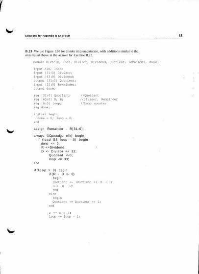
Solutions for Appendix B ExordsM
B.23 We use Figure 3.10 for divider implementation, with additions similar to theones listed above in the answer for Exercise B.22.
module DIVtclk, load. Divisor, Dividend, Quotient, Remainder, done);
input clk, 1oad;input [31:0] Divisor;input [63:0] Dividend:output [31:0] Quotient;input [31:0] Remainder;output done;
reg [31:0] Quotient; //Quotientreg [63:0] D, R; //Divisor, Remainderreg [6:0] loop; //Loop counterreg done;
initial begindone = 0; 1oop = 0;
end
assign Remainder - R [31 :0 ] ;
always ©Cposedge e lk) beginif ( load SS loop —0) begin
done <= 0;R <=Dividend;D <- Div isor << 32;
Quotient <-0;loop <= 33;
end
i f f l o o p > 0) begini f ( R - D >- 0)
beginQuotient <= (Ouotient << 1) + 1;R <- R - D;end
elsebeginQuotient <= Quotient << 1;
end
D <- D » 1:loop <= loop - 1;

Solution* for Appendix B E M K I M S
i fdoop -~ 0)done <= 1:
endendmodule
Note: This code does not check for division by zero (i.e., when Divisior - = 0) orfor quotient overflow (i.e., when Divisior < = Dividiend [64:32)).
B.24 The ALU-supported set less than (s 11) uses just the sign bit. In this case, ifwe try a set less than operation using the values -7 t e n and 6ten, we would get -7 >6. This is clearly wrong. Modify the 32-bit ALU in Figure 4.11 on page 169 to han-dle s 11 correctly by factor in overflow in the decision.
If there is no overflow, the calculation is done properly in Figure 4.17 and we sim-ply use the sign bit (Result31). If there is overflow, however, then the sign bit iswrong and we need the inverse of the sign bit.
0
1
1
1
01
1
1
0
LessThan = Overflow © Result31
OverflowIteuMl
0
1
1
0
1
1
1
0

Solutions for Appondlx B Exorcism
B.25 Given that a number that is greater than or equal to zero is termed positiveand a number that is less than zero is negative, inspection reveals that the last tworows of Figure 4.44 restate the information of the first two rows. Because A - B =A + (-B), the operation A - B when A is positive and B negative is the same as theoperation A + B when A is positive and B is positive. Thus the third row restatesthe conditions of the first. The second and fourth rows refer also to the same con-dition.
Because subtraction of two's complement numbers is performed by addition, acomplete examination of overflow conditions for addition suffices to show alsowhen overflow will occur for subtraction. Begin with the first two rows of Figure4.44 and add rows for A and B with opposite signs. Build a table that shows allpossible combinations of Sign and Carryin to the sign bit position and derive theCarryOut, Overflow, and related information. Thus,
0
000111
1
00
11001
0
10
1010
000
1011
0
1101
00
00101
01
NofesNoNoNo
NoYes
No
010
0001
0
Carries differIAI < IBI
IAI > IBIIAI > IBIIAI < iBI
Carries differ
From this table an Exclusive OR (XOR) of the Carryin and CarryOut of the signbit serves to detect overflow. When the signs of A and B differ, the value of theCarryin is determined by the relative magnitudes of A and B, as listed in the Notes
B.26 Cl = C4, C2 = C8, C3 = Cl2, and C4 = cl6.
c4 = G3,o + (Pi,o • cO).
c8 is given in the exercise.
cl2 = G,,j, + (Pu,8 • G,,4) + (P n , 8 • P,,4- G M ) + {Pn,»-P7,4 • P3.0 • cO).CIS = G15il2 + (P15,i2 • G,,,,) + (P,5,12 • P u , 8 • G7|4)
+ (Pl5,12 ' Pll,« • P7.4 • G3,0) + (Pl5,12 • Pll,» • P7.4 • P3.0 • CO).

Solutions for Appendix B EXOTCIM
B.27 The equations for c4, c8, and d2 are the same as those given in the solutionto Exercise 4.44. Using 16-bit adders means using another level of carry lookaheadlogic to construct the 64-bit adder. The second level generate, G(f, and propagate,PO', are
GO' = G15,o = Gis,12 + Pi5,12 • GU ,8 + Pl5,i2- P 1 U -G7.4 + P15 , l 2 • P l l j 8 • P7>4 • G3l0
and
Using GO' and PO', we can write cl6 more compactly as
cl6 = G1SiO + Pi5?o-cO
and
c32 = G 3 U 6 + P3 i i l 6 • cl6c48 = G47i32 + P47i32-c32c64 = G63,4g + P63,48-c48
A 64-bit adder diagram in the style of Figure B.6.3 would look like the foUowing:

Solutions for Appmidix B Exarclsaa
1Carryln
ALUOPOGO
rCarryln
ALU1P1G1
rCarryln
ALU2P2G2
rCarryln
ALU3P3
G3
C1
C2_
C3
C4I '
piQi
pi +1
Ql+1
ci + 2
pi+ 2gf +2
ci +3
pi +3
g i+3
Cf + 4
B.8.3 Four 4-Ut ALUs u»b« carry lookahaad to form a 16-btt «dder. Note that theime from the carry-2ookahead unit, not from the 4-bit ALUs.

Solutions for Appendix B Ex«rfl«M
B.28 No solution provided.
B.29 No solution provided.
B.30 No solution provided.
B.31 No solution provided.
B.32 No solution provided.
B.33 No solution provided.
B.34 The longest paths through the top {ripple carry) adder organization in Fig-ure B. 14.1 all start at input aO or bO and pass thrdiigh seven full adders on the wayto output s4 or s5. There are many such paths, all with a time delay of 7 x 2T = 14T.The longest paths through the bottom (carry sale); adder all start at input bO, eO,fl), b l , el , or fl and proceed through six full adders to outputs s4 or s5. The timedelay for this circuit is only 6 x 2T = 12T.