solution-cast monolayers of cobalt crown ether ...kummelgroup.ucsd.edu/pubs/papers_dec2015/lu kwak...
TRANSCRIPT
Solution-Cast Monolayers of Cobalt Crown Ether Phthalocyanine onHighly Ordered Pyrolytic GraphiteHao Lu,†,‡ Iljo Kwak,†,§,# Jun Hong Park,§,# Katie O’Neill,‡ Taniyuki Furuyama,∥ Nagao Kobayashi,∥
Alan Seabaugh,‡ Andrew Kummel,§ and Susan K. Fullerton-Shirey*,‡,⊥
‡Department of Electrical Engineering, University of Notre Dame, Notre Dame, Indiana 46556, United States§Department of Chemistry and Biochemistry, #Materials Science & Engineering Program, University of California, San Diego, LaJolla, California 92093, United States∥Department of Chemistry, Tohoku University, Sendai, Japan
*S Supporting Information
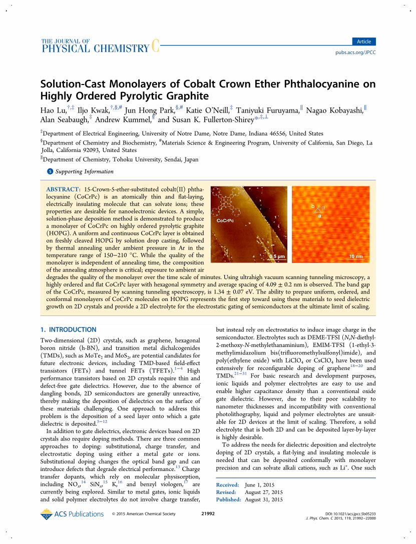
ABSTRACT: 15-Crown-5-ether-substituted cobalt(II) phtha-locyanine (CoCrPc) is an atomically thin and flat-laying,electrically insulating molecule that can solvate ions; theseproperties are desirable for nanoelectronic devices. A simple,solution-phase deposition method is demonstrated to producea monolayer of CoCrPc on highly ordered pyrolytic graphite(HOPG). A uniform and continuous CoCrPc layer is obtainedon freshly cleaved HOPG by solution drop casting, followedby thermal annealing under ambient pressure in Ar in thetemperature range of 150−210 °C. While the quality of themonolayer is independent of annealing time, the compositionof the annealing atmosphere is critical; exposure to ambient airdegrades the quality of the monolayer over the time scale of minutes. Using ultrahigh vacuum scanning tunneling microscopy, ahighly ordered and flat CoCrPc layer with hexagonal symmetry and average spacing of 4.09 ± 0.2 nm is observed. The band gapof the CoCrPc, measured by scanning tunneling spectroscopy, is 1.34 ± 0.07 eV. The ability to prepare uniform, ordered, andconformal monolayers of CoCrPc molecules on HOPG represents the first step toward using these materials to seed dielectricgrowth on 2D crystals and provide a 2D electrolyte for the electrostatic gating of semiconductors at the ultimate limit of scaling.
1. INTRODUCTION
Two-dimensional (2D) crystals, such as graphene, hexagonalboron nitride (h-BN), and transition metal dichalcogenides(TMDs), such as MoTe2 and MoS2, are potential candidates forfuture electronic devices, including TMD-based field-effecttransistors (FETs) and tunnel FETs (TFETs).1−4 Highperformance transistors based on 2D crystals require thin anddefect-free gate dielectrics. However, due to the absence ofdangling bonds, 2D semiconductors are generally unreactive,thereby making the deposition of dielectrics on the surface ofthese materials challenging. One approach to address thisproblem is the deposition of a seed layer onto which a gatedielectric is deposited.5−12
In addition to gate dielectrics, electronic devices based on 2Dcrystals also require doping methods. There are three commonapproaches to doping: substitutional, charge transfer, andelectrostatic doping using either a metal gate or ions.Substitutional doping changes the optical band gap and canintroduce defects that degrade electrical performance.13 Chargetransfer dopants, which rely on molecular physisorption,including NOx,
14 SiNx,15 K,16 and benzyl viologen,17 are
currently being explored. Similar to metal gates, ionic liquidsand solid polymer electrolytes do not involve charge transfer,
but instead rely on electrostatics to induce image charge in thesemiconductor. Electrolytes such as DEME-TFSI (N,N-diethyl-2-methoxy-N-methylethanaminium), EMIM-TFSI (1-ethyl-3-methylimidazolium bis(trifluoromethylsulfonyl)imide), andpoly(ethylene oxide) with LiClO4 or CsClO4 have been usedextensively for reconfigurable doping of graphene18−20 andTMDs.21−31 For basic research and development purposes,ionic liquids and polymer electrolytes are easy to use andenable higher capacitance density than a conventional oxidegate dielectric. However, due to their poor scalability tonanometer thicknesses and incompatibility with conventionalphotolithography, liquid and polymer electrolytes are unsuit-able for 2D devices at the limit of scaling. Therefore, a solidelectrolyte that is both 2D and can be deposited layer-by-layeris highly desirable.To address the needs for dielectric deposition and electrolyte
doping of 2D crystals, a flat-lying and insulating molecule isneeded that can be deposited conformally with monolayerprecision and can solvate alkali cations, such as Li+. One such
Received: June 1, 2015Revised: August 27, 2015Published: August 31, 2015
Article
pubs.acs.org/JPCC
© 2015 American Chemical Society 21992 DOI: 10.1021/acs.jpcc.5b05233J. Phys. Chem. C 2015, 119, 21992−22000

class of molecules is crown-ether-substituted phthalocyanine(Pc). Among the various crown ether metal Pc (MPc)molecules that can be obtained via peripheral substitution,15-crown-5-ether-substituted cobalt(II) phthalocyanine(CoCrPc), as shown in Figure 1, can solvate cations smaller
than the cavity size of the crown ethers and can lay flat on thesubstrate.32,33 The metal atom of the MPc interacts stronglywith the substrate,32,33 enabling the use of MPcs to seed atomiclayer deposition (ALD) growth of high-κ dielectrics.34,35 Whenthe MPc molecule is functionalized with crown ethers, such asCoCrPc, the molecule can solvate various alkali cations,33,36
providing a potential doping strategy for 2D crystals.MPcs and their derivatives can be deposited in an ultrahigh
vacuum (UHV) by molecular beam epitaxy (MBE) ontoAu(111),37 graphene,38−40 and TMDs34 to form perfectlyordered monolayers. Because of their excellent film growth andelectronic properties,41 an MPc monolayer can be used tonucleate ALD of wide band gap oxides, such as Al2O3.
34,35
Although MBE deposition of MPcs allows for precise control oflayer thickness for use as a crystalline multilayer, a monolayer ofMPcs also can be prepared by simple solution phase deposition,which is more practical for commercial application compared toMBE, because solution deposition can be done at atmosphericpressure. For example, Kong et al. prepared a monolayer ofTiOPc by drop casting from solution (1 μM TiOPc in toluene)onto freshly cleaved, highly ordered pyrolytic graphite (HOPG)and Au(111) under ambient conditions and performedscanning tunneling microscopy (STM) measurements.42
Their STM observations revealed that TiOPc molecules forma hexagonally packed monolayer on both substrates.Previously, Yoshimoto and co-workers prepared a CoCrPc
monolayer on both Au(100) and (111) and characterized thesurfaces with STM.32,33 The CoCrPc monolayer was formed byimmersing the Au substrate for 5 min in a benzene−ethanol(9:1 v/v) solution saturated with CoCrPc, followed by anultrapure water rinse. STM measurements of the CoCrPc,made in 0.05 M HClO4, confirmed that the molecules form anordered, flat-lying array parallel to the Au surface and theCoCrPc layer had 4-fold symmetry, with spacing of 2.5 nm.32,33
They also showed that the crown ether moieties of CoCrPc cantrap Ca2+ by making molecule−ion pairs. The imaging wasperformed in solution, where solvent−CoCrPc interactionsmay help stabilize the CoCrPc and facilitate the formation of amonolayer. In addition, strong interactions between the Ausubstrate and the phthalocyanine molecules may help topromote monolayer formation more than phthalocyaninedeposited on a graphene substrate.39
In this report, the solution phase deposition of a CoCrPcmonolayer on HOPG is presented. The monolayer wasprepared by solution drop casting, followed by annealing inAr at ambient pressure. Because both HOPG and grapheneshare the same surface chemistry, originating from sp3
hybridization, it is reasonable to regard HOPG and grapheneas equivalent for the purposes of this study. The solutiondeposition and annealing conditions were optimized bycharacterizing the surfaces with atomic force microscopy(AFM). Using UHV-STM, the surface morphology and thepacking structure of the monolayer were observed at themolecular level, and scanning tunneling spectroscopy (STS)was used to directly probe the band gap of the monolayer.43
2. EXPERIMENTAL DETAILSCoCrPc was synthesized following a previously publishedprocedure.33 Because the crown ether ligands make themolecule hygroscopic,44 monolayer deposition and AFMcharacterization were performed inside an Ar-filled glovebox(O2 and water < 0.1 ppm) and anhydrous solvents were used. Atotal of 1.3 mg CoCrPc was dissolved in a 100 mL mixture ofanhydrous benzene−ethanol (9:1 v/v, Sigma-Aldrich: 99.8%anhydrous benzene, 99.5% anhydrous ethanol). To improveCoCrPc dispersion in the solvent, the solution was enclosed ina glass vial with a screw-top lid, removed from the glovebox,and sonicated for 60 min at 40 kHz (Branson Sonicator 2510).The solution was returned to the glovebox for samplepreparation.CoCrPc monolayers were deposited onto HOPG by drop
casting from solution followed by thermal annealing in an Ar-filled glovebox. The CoCrPc solution was deposited onto 1.2 ×1.2 cm pieces of HOPG (2 mm thick, ZYB grade, Bruker) usinga micropipettor with a drop volume of 25 μL. Scotch tape (3M)was used to cleave the HOPG. Subsequent drops were appliedafter the previous drop evaporated and the sample surfaceappeared dry. After drop casting, the sample was transferredonto a hot plate and annealed in the temperature range of 120−500 °C in an Ar ambient. After 30 min of annealing, thesamples were transferred through an airlock into the second bayof the glovebox for atomic force microscopy (AFM) measure-ments without air exposure.To determine how the quality of the CoCrPc monolayer
depends on air exposure, the solution was drop cast onto afreshly cleaved HOPG surface, dried in the glovebox, and thenbrought into air for annealing. The same sample was annealedon the hot plate at 150 °C for 5, 10, 15, and 35 min, and aftereach annealing period, the sample was returned to the gloveboxfor AFM measurements.The topography of CoCrPc monolayer was characterized
using AFM (Dimension Icon Scanning Probe Microscope,Bruker) in ScanAsyst/PeakForce Tapping mode with siliconnitride ScanAsyst-air probes (Bruker). During the character-ization, the box light and glovebox circulation were turned offto minimize noise. Line profiles were used to measure thethickness of a CoCrPc monolayer on a sample prepared withpartial surface coverage.Monolayer formation of CoCrPc was confirmed by STM.
After drop casting 2 drops on freshly cleaved HOPG, thesample was annealed in a N2-filled convection oven (Carbolite301) for 20 min at 180 °C at ambient pressure. The sample wasimmediately loaded into an Omicron multichamber ultrahighvacuum system with base pressure less than 1 × 10⁻¹⁰ Torr.The sample topography was observed with a VT-STM
Figure 1. (a) Schematic diagram of the chemical structure of 15-crown-5-ether-substituted cobalt(II) phthalocyanine (CoCrPc) and(b) schematic side view of CoCrPc on HOPG.
The Journal of Physical Chemistry C Article
DOI: 10.1021/acs.jpcc.5b05233J. Phys. Chem. C 2015, 119, 21992−22000
21993

(Omicron Nanotechnology) with tungsten tips made byelectrochemically etching a tungsten wire. All STM imageswere acquired in constant current mode (I = 0.2 nA) with asample bias of −1.8 V. STS was used to measure the band gapof monolayer CoCrPc using a variable z-mode with externallock-in amplifier in the sample bias range from −1.5 to 1.5 V. Inaddition, a bare HOPG surface was measured as a control.
3. RESULTS AND DISCUSSION
3.1. Surface Morphology of the CoCrPc Monolayerand Annealing Temperature Window. After drop castingand solvent evaporation, the annealing temperature was variedbetween 120 and 500 °C to determine the optimumtemperature range for obtaining a CoCrPc monolayer. Theannealing time was fixed at 30 min; however, the quality of theCoCrPc monolayer was insensitive to annealing time in therange of 5 to 60 min. A total of two 25 μL drops (34 μL/cm2)provide full coverage on a 1.44 cm2 HOPG surface. AFMimages of the CoCrPc, as deposited on HOPG and after 30 minof annealing at five temperatures between 120−220 °C, areshown in Figure 2. Large particles line the step edges of theHOPG and are scattered randomly on the mesas. The lateralparticle size and height vary between 10−100 nm and 1−10nm, respectively. The particles are either impurities orundissolved CoCrPc aggregates; it is more likely that theparticles are aggregates because their size and density decreasewith annealing temperature.The as-deposited film (Figure 2a) shows uneven coverage of
CoCrPc. After annealing at 120 °C, full coverage is notachieved (Figure 2b); however, the CoCrPc thickness is at leastone monolayer, as shown by line scans in Figure S2 with stepheights of ∼0.5 nm. Note that the shape of the large particleschanges from irregular to spherical after annealing at 120 °C.Annealing in the temperature range of 150−210 °C (Figure2c−e) yields nearly complete CoCrPc coverage on the mesas asthe CoCrPc film becomes continuous and uniform. The
continuity of the CoCrPc film is broken along the mesa edgesand near the particles. The dose of CoCrPc was optimized toprovide the minimum amount of material required to cover thearea of the HOPG substrate without observable CoCrPcvacancy islands (i.e., a single monolayer). When the dose ofCoCrPc is insufficient to cover the entire area of the HOPGsubstrate, discontinuous islands are formed with veins joiningthem. Figure 3 represents an extreme case for which the dose is
Figure 2. AFM images of a 15-crown-5-ether-substituted cobalt(II) phthalocyanine (CoCrPc) monolayer on HOPG prepared by drop casting 34μL/cm2 of 13 mg/L CoCrPc benzene−ethanol (9:1 v/v) solution: (a) As-deposited film, (b) annealed in Ar for 30 min at 120, (c) 150, (d) 180, (e)210, and (f) 220 °C. All images are 2 × 2 μm2. The white particles are likely CoCrPc aggregates. Line scans of (a)−(c) are shown in Figures S1−S3in the Supporting Information.
Figure 3. AFM of CoCrPc monolayer with partial coverage: (a) 2 × 2μm2 AFM image of CoCrPc monolayer with partial surface coverageby depositing 8 μL/cm2 of 13 mg/L CoCrPc benzene−ethanol (9:1 v/v) solution and Ar annealing at 150 °C for 30 min and (b) line scancorresponding to the yellow line in part (a).
The Journal of Physical Chemistry C Article
DOI: 10.1021/acs.jpcc.5b05233J. Phys. Chem. C 2015, 119, 21992−22000
21994

so small that isolated CoCrPc patches are formed. When thedose of CoCrPc exceeds that needed for a single monolayer, asecond layer of islands start to form, nucleating primarily at thestep edges of the HOPG substrate. When the annealingtemperature increases beyond 210 °C, the upper bound of theoptimal annealing temperature window is reached, and thequality of the CoCrPc film starts to deteriorate (Figure 2f).To measure the thickness of a single CoCrPc layer after 150
°C anneal, 12 μL of CoCrPc solution (8 μL/cm2) was used tointentionally provide incomplete coverage (Figure 3a). Thethickness of the layer, 0.46 ± 0.01, nm is quantified byaveraging 10 line scan over a large CoCrPc island (Figure 3b).This agrees with the thickness of an individual CoCrPcmolecule measured by STM (0.42 nm),33 indicating that theCoCrPc molecules lie flat on the HOPG surface. The line scanalso indicates that the CoCrPc forms a uniform monolayer overthe distance of the line scan.
Within the annealing window of 150−210 °C, the quality ofthe coverage and the layer thickness are insensitive totemperature. However, as mentioned above, at an annealingtemperature of 220 °C, the CoCrPc monolayer becomesinhomogeneous. The monolayer continues to degrade withincreasing temperature, as shown by the AFM scans in Figure 4,where the annealing temperature is varied from 230 to 500 °C.Specifically, the presence of large, nonspherical aggregates isobserved at T > 300 °C. It is expected that the ether bonds inthe crowns of the CoCrPc decompose at T > 300 °C, furthercontributing to the significant change in the surfacemorphology at T = 500 °C.The surface roughness is quantified as a function of
temperature in Figure 5a by averaging over five area scans ofsize 0.3 × 0.3 μm2. At temperatures below 210 °C, the surfaceroughness decreases with increasing annealing temperature by afactor of ∼4; however, at temperatures larger than 240 °C,surface roughness increases by a factor of ∼6 as the CoCrPc
Figure 4. AFM images of degrading CoCrPc monolayer on HOPG. The CoCrPc monolayer was prepared by drop casting 34 μL/cm2 of 13 mg/LCoCrPc benzene−ethanol (9:1 v/v) and (a) annealed in Ar for 30 min at 230, (b) 240, (c) 300, and (d) 500 °C. All images are 2 × 2 μm2. A linescan of (d) is shown in Figure S3 in the Supporting Information.
Figure 5. Statistical analysis of as-deposited and annealed CoCrPc from AFM scans in Figures 2 and 4. (a) Root mean squared roughness (Rq) ofbare HOPG and as-deposited and annealed CoCrPc within the temperature range of 120−500 °C (n = 5). The roughness data is taken on the mesawhere a continuous CoCrPc monolayer is formed. (b) Particle height, (c) area, and (d) diameter of CoCrPc annealed within the temperature rangeof 120−300 °C. All errors are standard errors.
The Journal of Physical Chemistry C Article
DOI: 10.1021/acs.jpcc.5b05233J. Phys. Chem. C 2015, 119, 21992−22000
21995

molecules rearrange and aggregate. It is possible that theCoCrPc molecules are partially desorbing from the surface at T≥ 240 °C, contributing to the increased surface roughness.In addition to surface roughness, the height, area, and
diameter of the spherical particles observed at T ≤ 300 °C arequantified in Figure 5b−d by averaging over all particles in theAFM images in Figures 2 and 4a−c. Generally, the size of thespherical particles decreases with increasing temperature,suggesting that they are aggregates of CoCrPc. The scan at500 °C is excluded from the analysis because, at high
temperature, the molecules acquire sufficient thermal energythat they aggregate into nonspherical clusters that aresignificantly larger than the size of the original aggregatesobserved at T ≤ 300 °C.
3.2. Effect of Air Exposure. To characterize the stability ofthe CoCrPc films in air, samples were prepared in Ar by dropcasting without annealing, then transferred from the gloveboxand annealed in air at 150 °C for varying amounts of time. Asshown in Figure 6, the quality of the CoCrPc monolayerdegrades significantly compared to samples prepared under Ar
Figure 6. AFM images of a CoCrPc monolayer after air anneal. A thin CoCrPc film was prepared on HOPG by drop casting 34 μL/cm2 of 13 mg/LCCP benzene−ethanol (9:1 v/v) solution and (a) annealed in air at 150 °C for 5 min, (b) an additional 5 min, (c) an additional 5 min, and (d) anadditional 20 min. The total annealing time is 5, 10, 15, and 35 min. (e) Line scan following the yellow line in AFM image (b), and (f) line scanfollowing the yellow line in image (d). All AFM images are 2 × 2 μm2.
Figure 7. Statistical analysis of particle density and size observed in Figure 6 as a function of annealing time in air: (a) particle density, (b) height, (c)area, and (d) diameter of CoCrPc annealed in air at 150 °C. All errors are standard errors.
The Journal of Physical Chemistry C Article
DOI: 10.1021/acs.jpcc.5b05233J. Phys. Chem. C 2015, 119, 21992−22000
21996

annealing. The morphology of the CoCrPc monolayer changesdramatically when the annealing time increases from 5−10 minto 15−35 min. Because of the morphological similarity of theimages before 10 min and after, Figure 5a and b are denoted asannealing stage 1, and Figure 5c and d are denoted as annealingstage 2. In annealing stage 1, instead of forming a continuousmonolayer, the CoCrPc molecules form clusters, some of whichhave small spacing, ∼10 nm, and some large spacing, ∼50−100nm. In annealing stage 2, the CoCrPc clusters form a film thatis more continuous, but rough. As a result, large areas (∼0.5μm) with less CoCrPc coverage are created. As shown in theline scans in Figure 6e and f, the thickness of CoCrPc film ismeasured as 0.46 ± 0.03 nm (stage 1) and 0.46 ± 0.12 nm(stage 2) by averaging five line scans. The standard error of themeasured thickness of CoCrPc film annealed in air is 3 to 12times larger than those annealed in Ar, further indicating thatthe quality of the monolayer has degraded.The size and density of the spherical particles also change
significantly upon exposure to air while annealing. Based on theAFM scans in Figure 6, the particle density, height, area anddiameter are quantified in Figure 7 by averaging over allparticles in Figure 6a−d. The particle density decreases by a
factor of 2 between annealing stage 1 and stage 2. In addition,the particles in annealing stage 2 are smaller in height, area, anddiameter than those in annealing stage 1. Even when a sample isdeposited and annealed in the glovebox, postannealing airexposure at room temperature will degrade the quality of theCoCrPc monolayer (Figure S4 in Supporting Information),consistent with metal phthalocyanines ability of bond oxidizingmolecules.45
3.3. STM and STS. UHV STM was employed to confirmthat CoCrPc lies flat on HOPG. As mentioned above, a flat-lying CoCrPc molecule is required for both seeding ALDgrowth of high-κ gate dielectrics and electrostatic doping viaions located in the crowns. Using the same method as describedin the above AFM studies, 2 drops of 10 mg/L CoCrPc inanhydrous benzene−ethanol (9:1 v/v) were drop cast ontofreshly cleaved HOPG and annealed in 1 atm of N2 at 180 °Cfor 20 min. Note that the samples were transferred in air to theSTM and outgassed in UHV at 3 × 10⁻¹⁰ Torr for 10 min. Inaddition, a bare HOPG surface was measured as a control.Figure 8a shows a topographic STM image of bare HOPG, withlattice parameters a = 0.22 ± 0.07 nm, b = 0.21 ± 0.1 nm, andα = 58 ± 2°; the typical hexagonal symmetry of carbon atoms is
Figure 8. STM and STS of HOPG and drop cast and annealed CoCrPc on HOPG. (a) STM image of a bare HOPG surface with lattice parametersa = 0.22 ± 0.07 nm, b = 0.21 ± 0.1 nm, and α = 58 ± 2°. STM was measured with Vsample = −1.8 V and It = 0.2 nA at −180 °C. (b) STS dI/dV/(I/V) spectra (average of 20 measurements) of a bare HOPG sample showing no apparent energy gap. (c) Filled-state STM image of a CoCrPcmonolayer on HOPG with lattice parameters a = b = 4.08 ± 0.2 nm, α = 59 ± 1°. A highly ordered and flat CoCrPc layer with hexagonal latticestructure is observed. (d) STS dI/dV/(I/V) spectra of a CoCrPc layer on HOPG. STS curve shows that the CoCrPc layer has a 1.34 ± 0.07 eV bandgap. EF is the position of Fermi energy level, located at 0 V.
The Journal of Physical Chemistry C Article
DOI: 10.1021/acs.jpcc.5b05233J. Phys. Chem. C 2015, 119, 21992−22000
21997

observed. Figure 8c is a STM image of a solution castedCoCrPc layer on HOPG, where a highly ordered and flatCoCrPc layer is observed with hexagonal symmetry. Thispacking arrangement is different from the quadratic packinggeometry of CoCrPc deposited on Au(100) and (111),32,33
consistent with the substrate controlling the packing geometryof MPc molecules. However, in contrast to CoCrPc, TiOPcpacks hexagonally on both HOPG and Au(111), indicating thatboth the identity of the MPc and the substrate control packinggeometry.42 Kong et al. showed that unit cell parameters ofTiOPc on HOPG and Au(111) substrates are similar: a = b =1.3 ± 0.1 nm, α = 60 ± 1°; and a = b = 1.0 ± 0.2 nm, α = 60 ±2°, respectively.42 In the present study, the unit cell length ofCoCrPc on HOPG is significantly larger, a = b = 4.08 ± 0.2nm, α = 59 ± 1°, than TiOPc on HOPG. This is due, in part, tothe larger size of CoCrPc; however, the CoCrPc spacing is alsolarger than the previously reported spacing of CoCrPc onAu(111), 2.5 nm.33 The lower packing density of CoCrPC onHOPG compared to Au(111) is attributed to weaker bindingbetween CoCrPC and HOPG due to the lower electron densityof HOPG compared to Au.39 In contrast, the negligible spacingchange for TiOPc on both HOPG and Au is likely theconsequence of a much stronger molecule−substrate bindinginteraction due to the large dipole of TiOPc.46
Using STS, the normalized differential conductivity (dI/dV/(I/V)) of the bare HOPG and CoCrPc layer are measured as afunction of scan voltage (V), as shown in Figures 8b and d. Forthe sample covered in CoCrPc, the STS data were measured onthe center of the CoCrPc molecules. The scan bias was sweptfrom −1.5 to 1.5 V. A total of 20 STS curves were obtainedfrom different points and averaged to estimate the band gap.The dI/dV/(I/V) curve obtained on the bare HOPG surface isshown in Figure 8b. The curve has a parabolic shape, indicatingthere is no apparent energy gap due to the high conductivity ofthe HOPG sample. In contrast, the energy band gap is clearlyobserved in the sample covered by CoCrPc (Figure 8d). Thelocations of the valence-band maximum (EV) and conduction-band minimum (EC) are determined by assuming linear onsetsin the differential conductance in Figure 8d. Straight lines aredrawn through the spectra on either side of an onset, and theband edge onset position is obtained by the intersection of thelines and horizontal axis. The data indicate a valence band edge(left) and conduction band edge (right) at −0.58 ± 0.04 and0.76 ± 0.03 eV, respectively, giving a band gap of 1.34 ± 0.07eV.To our knowledge, this is the first reported measurement of
the band gap of CoCrPc with STS. This small band gap issimilar to previously reported values for other metalphthalocyanines on an HOPG substrate.39,47,48 For example,Park et al. reported a band gap of 1.75 eV for single layercopper phthalocyanine (CuPc) on HOPG.39 They also showthat the band gap depends on the number of layers: multilayerCuPc film has a band gap of 2.3 eV. The fact that the STSmeasurements in Figure 8d are uniform across the entire scanarea also supports the assertion that the CoCrPc coverage is asingle monolayer.
4. CONCLUSIONA monolayer of CoCrPc was deposited on HOPG by simpledrop casting from solution followed by thermal annealing in Arunder ambient pressure. The effects of annealing temperatureand air exposure on the CoCrPc layer were characterized. Auniform and continuous film was obtained by Ar annealing in
the temperature range of 150−210 °C, nearly independent ofannealing time. However, the quality and coverage of theCoCrPc layer degraded over time by air annealing, and whenthe sample was exposed to air after argon annealing. Therefore,an inert environment is needed to maintain the quality of themonolayer on HOPG. STM shows that the CoCrPc monolayerlays flat on the HOPG surface with hexagonal symmetry, andfor the first time, the band gap of the CoCrPc monolayer wasmeasured by STS. This study lays the groundwork for using amonolayer of CoCrPc molecules in nanoelectronic devices asan ion conductor or as a seeding layer for ALD growth on 2Dcrystals. When complexed with alkali cations, the CoCrPcmolecules could be used as a 2D electrolyte for electrostaticdoping or memory in 2D crystals.
■ ASSOCIATED CONTENT*S Supporting InformationThe Supporting Information is available free of charge on theACS Publications website at DOI: 10.1021/acs.jpcc.5b05233.
Line scans of as-deposited CoCrPc and annealed at 120°C; line scans and roughness of bare HOPG, andCoCrPc annealed at 150 and 500 °C; AFM of Ar-annealed CoCrPc after 15 min and 48 h of air exposure(PDF)
■ AUTHOR INFORMATIONCorresponding Author*Phone: +1 (412) 624-2079. E-mail: [email protected] Address⊥Department of Chemical and Petroleum Engineering,University of Pittsburgh, Pittsburgh, PA, U.S.A. (S.K.F.-S.).Author Contributions†These authors contributed equally (H.L. and I.K.).NotesThe authors declare no competing financial interest.
■ ACKNOWLEDGMENTSThis work was supported in part by the Center for Low EnergySystems Technology (LEAST), one of the six SRC STARnetCenters, sponsored by MARCO and DARPA, the NSF underGrant Nos. ECCS-GOALI-1408425 and DMR-1207213.
■ REFERENCES(1) Das, S.; Prakash, A.; Salazar, R.; Appenzeller, J. Toward Low-Power Electronics: Tunneling Phenomena in Transition MetalDichalcogenides. ACS Nano 2014, 8, 1681−1689.(2) Fiori, G.; Bonaccorso, F.; Iannaccone, G.; Palacios, T.; Neumaier,D.; Seabaugh, A.; Banerjee, S. K.; Colombo, L. Electronics Based onTwo-Dimensional Materials. Nat. Nanotechnol. 2014, 9, 768−779.(3) Jena, D. Tunneling Transistors Based on Graphene and 2-DCrystals. Proc. IEEE 2013, 101, 1585−1602.(4) Wang, Q. H.; Kalantar-Zadeh, K.; Kis, A.; Coleman, J. N.; Strano,M. S. Electronics and Optoelectronics of Two-Dimensional TransitionMetal Dichalcogenides. Nat. Nanotechnol. 2012, 7, 699−712.(5) Alaboson, J. M.; Wang, Q. H.; Emery, J. D.; Lipson, A. L.;Bedzyk, M. J.; Elam, J. W.; Pellin, M. J.; Hersam, M. C. SeedingAtomic Layer Deposition of High-κ Dielectrics on Epitaxial Graphenewith Organic Self-Assembled Monolayers. ACS Nano 2011, 5, 5223−5232.(6) Farmer, D. B.; Chiu, H. Y.; Lin, Y. M.; Jenkins, K. A.; Xia, F.;Avouris, P. Utilization of a Buffered Dielectric to Achieve High Field-Effect Carrier Mobility in Graphene Transistors. Nano Lett. 2009, 9,4474−4478.
The Journal of Physical Chemistry C Article
DOI: 10.1021/acs.jpcc.5b05233J. Phys. Chem. C 2015, 119, 21992−22000
21998
(7) Kim, S.; Nah, J.; Jo, I.; Shahrjerdi, D.; Colombo, L.; Yao, Z.;Tutuc, E.; Banerjee, S. K. Realization of a High Mobility Dual-GatedGraphene Field-Effect Transistor with Al2O3 Dielectric. Appl. Phys.Lett. 2009, 94, 062107.(8) Lee, B.; Park, S.-Y.; Kim, H.-C.; Cho, K.; Vogel, E. M.; Kim, M. J.;Wallace, R. M.; Kim, J. Conformal Al2O3 Dielectric Layer Depositedby Atomic Layer Deposition for Graphene-Based Nanoelectronics.Appl. Phys. Lett. 2008, 92, 203102.(9) McDonnell, S.; Brennan, B.; Azcatl, A.; Lu, N.; Dong, H.; Buie,C.; Kim, J.; Hinkle, C. L.; Kim, M. J.; Wallace, R. M. HfO2 on MoS2 byAtomic Layer Deposition: Adsorption Mechanisms and ThicknessScalability. ACS Nano 2013, 7, 10354−10361.(10) Sangwan, V. K.; Jariwala, D.; Filippone, S. A.; Karmel, H. J.;Johns, J. E.; Alaboson, J. M.; Marks, T. J.; Lauhon, L. J.; Hersam, M. C.Quantitatively Enhanced Reliability and Uniformity of High-κDielectrics on Graphene Enabled by Self-Assembled Seeding Layers.Nano Lett. 2013, 13, 1162−1167.(11) Shin, W. C.; Bong, J. H.; Choi, S. Y.; Cho, B. J. FunctionalizedGraphene as an Ultrathin Seed Layer for the Atomic Layer Depositionof Conformal High-K Dielectrics on Graphene. ACS Appl. Mater.Interfaces 2013, 5, 11515−11519.(12) Wang, X.; Tabakman, S. M.; Dai, H. Atomic Layer Depositionof Metal Oxides on Pristine and Functionalized Graphene. J. Am.Chem. Soc. 2008, 130, 8152−8153.(13) Gong, Y.; et al. Band Gap Engineering and Layer-by-LayerMapping of Selenium-Doped Molybdenum Disulfide. Nano Lett. 2014,14, 442−449.(14) Zhao, P.; et al. Air Stable p-Doping of WSe2 by CovalentFunctionalization. ACS Nano 2014, 8, 10808−10814.(15) Chen, K.; Kiriya, D.; Hettick, M.; Tosun, M.; Ha, T. J.;Madhvapathy, S. R.; Desai, S.; Sachid, A.; Javey, A. Air Stable n-Dopingof WSe2 by Silicon Nitride Thin Films with Tunable Fixed ChargeDensity. APL Mater. 2014, 2, 092504.(16) Fang, H.; Tosun, M.; Seol, G.; Chang, T. C.; Takei, K.; Guo, J.;Javey, A. Degenerate n-Doping of Few-Layer Transition MetalDichalcogenides by Potassium. Nano Lett. 2013, 13, 1991−1995.(17) Kiriya, D.; Tosun, M.; Zhao, P.; Kang, J. S.; Javey, A. Air-StableSurface Charge Transfer Doping of MoS2 by Benzyl Viologen. J. Am.Chem. Soc. 2014, 136, 7853−7856.(18) Das, A.; et al. Monitoring Dopants by Raman Scattering in anElectrochemically Top-Gated Graphene Transistor. Nat. Nanotechnol.2008, 3, 210−215.(19) Efetov, D. K.; Kim, P. Controlling Electron-Phonon Interactionsin Graphene at Ultrahigh Carrier Densities. Phys. Rev. Lett. 2010, 105,256805.(20) Efetov, D. K.; Maher, P.; Glinskis, S.; Kim, P. MultibandTransport in Bilayer Graphene at High Carrier Densities. Phys. Rev. B:Condens. Matter Mater. Phys. 2011, 84, 161412.(21) Lin, M.-W.; Liu, L.; Lan, Q.; Tan, X.; Dhindsa, K. S.; Zeng, P.;Naik, V. M.; Cheng, M. M.-C.; Zhou, Z. Mobility Enhancement andHighly Efficient Gating of Monolayer MoS2 Transistors with PolymerElectrolyte. J. Phys. D: Appl. Phys. 2012, 45, 345102.(22) Pu, J.; Yomogida, Y.; Liu, K. K.; Li, L. J.; Iwasa, Y.; Takenobu, T.Highly Flexible MoS2 Thin-Film Transistors with Ion Gel Dielectrics.Nano Lett. 2012, 12, 4013−4017.(23) Zhang, Y.; Ye, J.; Matsuhashi, Y.; Iwasa, Y. Ambipolar MoS2Thin Flake Transistors. Nano Lett. 2012, 12, 1136−1140.(24) Perera, M. M.; Lin, M. W.; Chuang, H. J.; Chamlagain, B. P.;Wang, C.; Tan, X.; Cheng, M. M.; Tomanek, D.; Zhou, Z. ImprovedCarrier Mobility in Few-Layer MoS2 Field-Effect Transistors withIonic-Liquid Gating. ACS Nano 2013, 7, 4449−4458.(25) Yuan, H. T.; et al. Zeeman-Type Spin Splitting Controlled by anElectric Field. Nat. Phys. 2013, 9, 563−569.(26) Zhang, Y. J.; Ye, J. T.; Yomogida, Y.; Takenobu, T.; Iwasa, Y.Formation of a Stable p-n Junction in a Liquid-Gated MoS2 AmbipolarTransistor. Nano Lett. 2013, 13, 3023−3028.(27) Allain, A.; Kis, A. Electron and Hole Mobilities in Single-LayerWSe2. ACS Nano 2014, 8, 7180−7185.
(28) Chuang, H. J.; Tan, X.; Ghimire, N. J.; Perera, M. M.;Chamlagain, B.; Cheng, M. M.; Yan, J.; Mandrus, D.; Tomanek, D.;Zhou, Z. High Mobility WSe2 p- and n-Type Field-Effect TransistorsContacted by Highly Doped Graphene for Low-Resistance Contacts.Nano Lett. 2014, 14, 3594−3601.(29) Lezama, I. G.; Ubaldini, A.; Longobardi, M.; Giannini, E.;Renner, C.; Kuzmenko, A. B.; Morpurgo, A. F. Surface Transport andBand Gap Structure of Exfoliated 2H-MoTe2 Crystals. 2D Mater.2014, 1, 021002.(30) Zhang, Y. J.; Oka, T.; Suzuki, R.; Ye, J. T.; Iwasa, Y. ElectricallySwitchable Chiral Light-Emitting Transistor. Science 2014, 344, 725−728.(31) Xu, H.; Fathipour, S.; Kinder, E. W.; Seabaugh, A. C.; Fullerton-Shirey, S. K. Reconfigurable Ion Gating of 2H-MoTe2 Field-EffectTransistors Using Poly(Ethylene Oxide)-CsClo4 Solid PolymerElectrolyte. ACS Nano 2015, 9, 4900−4910.(32) Yoshimoto, S.; Suto, K.; Itaya, K.; Kobayashi, N. Host-GuestRecognition of Calcium by Crown-Ether Substituted PhthalocyanineArray on Au(111): Relationship between Crown Moieties and GoldLattice. Chem. Commun. 2003, 2174−2175.(33) Yoshimoto, S.; Suto, K.; Tada, A.; Kobayashi, N.; Itaya, K. Effectof Adlayer Structure on the Host−Guest Recognition betweenCalcium and Crown-Ether-Substituted Phthalocyanine Arrays on AuSingle-Crystal Surfaces. J. Am. Chem. Soc. 2004, 126, 8020−8027.(34) Park, J. H.; Kwak, I.; Sardashti, K.; Kaufman-Osborn, T.; Park, S.W.; Kummel, A. C. Ultrathin Titanyl Phthalocyanine Monolayers onGraphene for Dielectrics and Ordered ALD Nucleation. 2014 MRSSpring Meeting and Exhibit, San Francisco, CA, April 21−25, 2014,Materials Research Society: Warrendale, PA, 2014.(35) Fathipour, S.; Park, J. H.; Kummel, A.; Seabaugh, A. Low-Leakage WSe2 FET Gate-Stack Using Titanyl Phthalocyanine SeedingLayer for Atomic Layer Deposition of Al2O3. 2015 Dev. Res. Conf.,Columbus, OH, June 21−24, 2015, Materials Research Society:Warrendale, PA, 2014.(36) De, S.; Boda, A.; Ali, S. M. Preferential Interaction of ChargedAlkali Metal Ions (Guest) within a Narrow Cavity of Cyclic CrownEthers (Neutral Host): A Quantum Chemical Investigation. J. Mol.Struct.: THEOCHEM 2010, 941, 90−101.(37) Cheng, Z. H.; Gao, L.; Deng, Z. T.; Liu, Q.; Jiang, N.; Lin, X.;He, X. B.; Du, S. X.; Gao, H. J. Epitaxial Growth of IronPhthalocyanine at the Initial Stage on Au(111) Surface. J. Phys.Chem. C 2007, 111, 2656−2660.(38) Wang, S. D.; Dong, X.; Lee, C. S.; Lee, S. T. Orderly Growth ofCopper Phthalocyanine on Highly Oriented Pyrolytic Graphite(HOPG) at High Substrate Temperatures. J. Phys. Chem. B 2004,108, 1529−1532.(39) Park, J. H.; Choudhury, P.; Kummel, A. C. NO Adsorption onCopper Phthalocyanine Functionalized Graphite. J. Phys. Chem. C2014, 118, 10076−10082.(40) Xie, W. G.; Xu, J. B.; An, J.; Xue, K. Correlation betweenMolecular Packing and Surface Potential at Vanadyl Phthalocyanine/HOPG Interface. J. Phys. Chem. C 2010, 114, 19044−19047.(41) Guillaud, G.; Simon, J.; Germain, J. P. Metallophthalocyanines -Gas Sensors, Resistors and Field Effect Transistors. Coord. Chem. Rev.1998, 178, 1433−1484.(42) Kong, X.-H.; Yang, Y.-L.; Lei, S.-B.; Wang, C. On theTopography Multiplicity of Non-Planar Titanyl (IV) PhthalocyanineMolecules and the STM Imaging Mechanism. Surf. Sci. 2008, 602,684−692.(43) Feenstra, R. M. Scanning Tunneling Spectroscopy. Surf. Sci.1994, 299−300, 965−979.(44) Smith, G. D.; Bedrov, D.; Borodin, O. Molecular DynamicsSimulation Study of Hydrogen Bonding in Aqueous Poly(EthyleneOxide) Solutions. Phys. Rev. Lett. 2000, 85, 5583−5586.(45) Passard, M.; Pauly, A.; Blanc, J.-P.; Dogo, S.; Germain, J. P.;Maleysson, C. Doping Mechanisms of Phthalocyanines by OxidizingGases: Application to Gas Sensors. Thin Solid Films 1994, 237, 272−276.
The Journal of Physical Chemistry C Article
DOI: 10.1021/acs.jpcc.5b05233J. Phys. Chem. C 2015, 119, 21992−22000
21999

(46) Fukagawa, H.; Yamane, H.; Kera, S.; Okudaira, K. K.; Ueno, N.Experimental Estimation of the Electric Dipole Moment andPolarizability of Titanyl Phthalocyanine Using Ultraviolet Photo-electron Spectroscopy. Phys. Rev. B: Condens. Matter Mater. Phys. 2006,73, 73.(47) Schwieger, T.; Peisert, H.; Golden, M. S.; Knupfer, M.; Fink, J.Electronic Structure of the Organic Semiconductor CopperPhthalocyanine and K-CuPc Studied Using Photoemission Spectros-copy. Phys. Rev. B: Condens. Matter Mater. Phys. 2002, 66, 155207.(48) Hill, I. G.; Kahn, A.; Soos, Z. G.; Pascal, R. A., Jr. Charge-Separation Energy in Films of π-Conjugated Organic Molecules. Chem.Phys. Lett. 2000, 327, 181−188.
The Journal of Physical Chemistry C Article
DOI: 10.1021/acs.jpcc.5b05233J. Phys. Chem. C 2015, 119, 21992−22000
22000