solid state relays 3-phase with integrated heatsink types ... · pdf fileminimum operational...
TRANSCRIPT

Specifications are subject to change without notice (19.12.2017) 1
Solid state relayNumber of switched polesSwitching modeRated operational voltageControl voltageRated operational currentConnection type for controlConnection type for powerConnection configurationExternal supplyIntegrated fanMonitoring features
• 2-pole & 3-pole switching AC solid state contactors• Product width up to 70mm• Rated operational voltage: up to 660VAC• Rated operational current: up to 75AAC• Control voltages: 5-32VDC, 20-275VAC (24-190 VDC)• Up to 15,000A²s for I²t• Motor ratings up to 11 kW @ 400VAC, 25HP @ 600VAC• Integrated varistor protection on output• Optional monitoring for SSR and load malfunction (RGC..M)1• EMR alarm output and auxiliary output (RGC..M)• Controlled fan operation for versions with integrated fan• 100kA Short Circuit Current Rating according to UL508• DIN or panel mount
1: RGC..M is suitable only for resistive loads2: Applicable only to RGC...10
Product Description Ordering Key
This product is intended toreplace mechanical contactorsespecially when switching isfrequent. The smallest productwidth in the RGC2, RGC3 rangeis 54mm (3xDIN) and goes up to70mm. 2-pole and 3-poleswitching options are available.
Apart from resistive and slightlyinductive loads, the RGC iscertified for motor switching withassociated motor ratings. Agreen LED gives indication ofcontrol voltage presence. Fan
operation is controlled for theversions which have anintegrated fan.
Detection of SSR overheat,mains loss, SSR malfunctionand load loss is possible with theRGC..M versions. An EMRalarm output is available forremote signaling. An additionalfeature with the RGC..M is theelectronic auxiliary output. TheRGC..M has additional LEDs forload status and alarm statusindication.
Solid State Relays3-Phase with Integrated HeatsinkTypes RGC2, RGC3
Ordering Key (refer to page 2 for available part nos.)
RGC 3 A 60 D 65 G G E D F M
SSR with Rated Control Rated current/ Connection Connection Connection External Features heatsink voltage voltage6 pole @40°C3 control power configuration supply (Ue)5, (Uc) (Us) Blocking
voltage
RGC2A: 22: D: 10: 10AAC K: Screw K: Screw E: Contactor D: 24VDC F: Integrated fan with over2-pole switching + 42-242VAC, 5 - 32VDC 25: 25AAC G: Box Clamp G: Box Clamp A: 90-250VAC temperature protection (OTP) &1-pole direct, ZC 800Vp 40: 40AAC EMR alarm output
75: 75AAC60: A: M: Monitoring for Mains loss, 42-660VAC, 20-275VAC, Load loss, SSR short circuit,1200Vp 24-190VDC open circuit and over-
temperature with EMR alarm output and auxiliary output1
RGC3A: 22: D: 10: 10AAC K: Screw K: Screw E: Contactor D: 24VDC F: Integrated fan with over3-pole switching 42-242VAC, 5 - 32VDC 20: 20AAC G: Box Clamp G: Box Clamp A: 90-250VAC temperature protection (OTP) &ZC4 800Vp 25: 25AAC EMR alarm output
30: 30AAC60: A: 40: 40AAC M: Monitoring for Mains loss, 42-660VAC, 20-275VAC, 65: 65AAC Load loss, SSR short circuit,1200Vp 24-190VDC open circuit and over-
temperature with EMR alarm output and auxiliary output1
(suitable only for resistive loads)
2
Specifications are at a surrounding temperature of 25°C unlessotherwise specified.
3. Refer to Current Derating curves
4. ZC= Zero Cross Switching
5. Operating voltage for RGC..M starts from 90VAC
6. AC control range for RGC..A..A.. is limited to 20-275VAC only
s

2 Specifications are subject to change without notice (19.12.2017)
RGC2, RGC3
Selection Guide: RGC2 (2-pole switching, 1-pole direct)
Selection Guide: RGC3 (3-pole switching)
Selection Guide: RGC2..M (2-pole switching, 1-pole direct with monitoring)
Selection Guide: RGC3..M (3-pole switching with monitoring)
KKE: input terminals = screw, output terminals = screwKGE: input terminals = screw, output terminals = box clamp
GKE: input terminals = box clamps, output terminals = screwGGE: input terminals = box clamps, output terminals = box clamp
Rated outputvoltage, Ue
Control voltage,Uc
Features External supply, Us
Rated operational current @ 40°C (I²t)Product width
10 AAC/pole(1,800A²s)54mm
25 AAC/pole(1,800A²s)54mm
-40 AAC/pole (6,600A²s)70mm
-75 AAC/pole(15,000A²s)70mm + fan
220 VAC 5-32 VDC - - - RGC2A22D25KKE - - - -
20-275 VAC, 24-190 VDC
- - - RGC2A22A25KKE - - -
600 VAC 5-32 VDC - - RGC2A60D10KKE RGC2A60D25KKE - RGC2A60D40KGE - -
OTP 24 VDC - - - - - RGC2A60D75GGEDF
OTP 90-250 VAC - - - - - RGC2A60D75GGEAF
20-275 VAC, 24-190 VDC
- - RGC2A60A10KKE RGC2A60A25KKE - RGC2A60A40KGE - -
20-275 VAC OTP 90-250 VAC - - - - - RGC2A60A75GGEAF
Rated outputvoltage, Ue
Control voltage,Uc
Features External supply, Us
Rated operational current @ 40°C (I²t)Product width
10 AAC/pole(1,800A²s)54mm
20 AAC/pole(1,800A²s)54mm
25 AAC/pole(1,800A²s)70mm
30 AAC/pole (6,600A²s)70mm
40 AAC/pole(6,600A²s)54mm + fan
65 AAC/pole(15,000A²s)70mm + fan
Rated outputvoltage, Ue
Control voltage,Uc
Features External supply, Us
Rated operational current @ 40°C (I²t)Product width
-25 AAC /pole(1,800A²s)54mm
-40 AAC /pole (6,600A²s)70mm
-75 AAC /pole(15,000A²s)70mm + fan
Rated outputvoltage, Ue
Control voltage,Uc
Features External supply, Us
Rated operational current @ 40°C (I²t)Product width
- 20 AAC /pole(1,800A²s)54mm
25 AAC /pole(1,800A²s)70mm
30 AAC /pole (6,600A²s)70mm
- 65 AAC /pole(15,000A²s)70mm + fan
220VAC5-32 VDC - - RGC3A22D10KKE RGC3A22D20KKE - - - -20-275 VAC, 24-190 VDC
- - RGC3A22A10KKE RGC3A22A20KKE - - - -
600VAC 5-32 VDC - - RGC3A60D10KKE RGC3A60D20KKE RGC3A60D25KKE RGC3A60D30KGE - -
OTP 24VDC - - - RGC3A60D40GGEDF RGC3A60D65GGEDF
OTP 90-250VAC - - - - RGC3A60D65GGEAF
20-275 VAC, 24-190 VDC
- - RGC3A60A10KKE RGC3A60A20KKE RGC3A60A25KKE RGC3A60A30KGE - -
20-275 VAC OTP 90-250VAC - - - RGC3A60A40GGEAF RGC3A60A65GGEAF
600 VAC 5-32 VDC Monitoring 24 VDC - RGC2A60D25GKEDM - RGC2A60D40GGEDM - RGC2A60D75GGEDFM
Monitoring 90-250 VAC - RGC2A60D25GKEAM - RGC2A60D40GGEAM - RGC2A60D75GGEAFM
20-275 VAC Monitoring 90-250 VAC - RGC2A60A25GKEAM - RGC2A60A40GGEAM - RGC2A60A75GGEAFM
600VAC 5-32VDC Monitoring 24 VDC - RGC3A60D20GKEDM RGC3A60D25GKEDM RGC3A60D30GGEDM - RGC3A60D65GGEDFM
Monitoring 90-250 VAC - RGC3A60D20GKEAM RGC3A60D25GKEAM RGC3A60D30GGEAM - RGC3A60D65GGEAFM
20-275VAC Monitoring 90-250 VAC - RGC3A60A20GKEAM RGC3A60A25GKEAM RGC3A60A30GGEAM - RGC3A60A65GGEAFM
Specifications are subject to change without notice (19.12.2017) 3
RGC2, RGC3
7: Refer to Red LED Alarm Indications
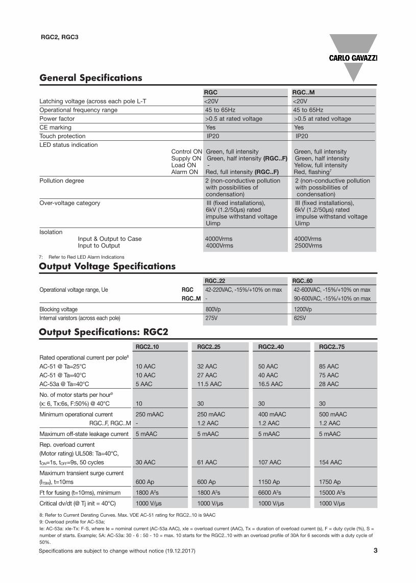
General SpecificationsRGC RGC..M
Latching voltage (across each pole L-T <20V <20VOperational frequency range 45 to 65Hz 45 to 65HzPower factor >0.5 at rated voltage >0.5 at rated voltageCE marking Yes YesTouch protection IP20 IP20LED status indication
Control ON Green, full intensity Green, full intensitySupply ON Green, half intensity (RGC..F) Green, half intensityLoad ON - Yellow, full intensityAlarm ON Red, full intensity (RGC..F) Red, flashing7
Pollution degree 2 (non-conductive pollution 2 (non-conductive pollutionwith possibilities of with possibilities ofcondensation) condensation)
Over-voltage category III (fixed installations), III (fixed installations),6kV (1.2/50µs) rated 6kV (1.2/50µs) rated impulse withstand voltage impulse withstand voltage Uimp Uimp
IsolationInput & Output to Case 4000Vrms 4000VrmsInput to Output 4000Vrms 2500Vrms
Output Voltage SpecificationsRGC..22 RGC..60
Operational voltage range, Ue RGC 42-220VAC, -15%/+10% on max 42-600VAC, -15%/+10% on maxRGC..M - 90-600VAC, -15%/+10% on max
Blocking voltage 800Vp 1200VpInternal varistors (across each pole) 275V 625V
Output Specifications: RGC2 RGC2..10 RGC2..25 RGC2..40 RGC2..75
Rated operational current per pole8
AC-51 @ Ta=25°C 10 AAC 32 AAC 50 AAC 85 AACAC-51 @ Ta=40°C 10 AAC 27 AAC 40 AAC 75 AACAC-53a @ Ta=40°C 5 AAC 11.5 AAC 16.5 AAC 28 AAC
No. of motor starts per hour9
(x: 6, Tx:6s, F:50%) @ 40°C 10 30 30 30
Minimum operational current 250 mAAC 250 mAAC 400 mAAC 500 mAACRGC..F, RGC..M - 1.2 AAC 1.2 AAC 1.2 AAC
Maximum off-state leakage current 5 mAAC 5 mAAC 5 mAAC 5 mAAC
Rep. overload current(Motor rating) UL508: Ta=40°C,tON=1s, tOFF=9s, 50 cycles 30 AAC 61 AAC 107 AAC 154 AAC
Maximum transient surge current (ITSM), t=10ms 600 Ap 600 Ap 1150 Ap 1750 Ap
I2t for fusing (t=10ms), minimum 1800 A2s 1800 A2s 6600 A2s 15000 A2s
Critical dv/dt (@ Tj init = 40°C) 1000 V/µs 1000 V/µs 1000 V/µs 1000 V/µs
8: Refer to Current Derating Curves. Max. VDE AC-51 rating for RGC2..10 is 9AAC9: Overload profile for AC-53a; Ie: AC-53a: xIe-Tx: F-S, where Ie = nominal current (AC-53a AAC), xIe = overload current (AAC), Tx = duration of overload current (s), F = duty cycle (%), S =number of starts. Example; 5A: AC-53a: 30 - 6 : 50 - 10 = max. 10 starts for the RGC2..10 with an overload profile of 30A for 6 seconds with a duty cycle of50%.

4 Specifications are subject to change without notice (19.12.2017)
RGC2, RGC3
Output Specifications: RGC3RGC30..10 RGC3..20 RGC3..25 RGC3..30 RGC3..40 RGC3..65
Rated operational current per pole8
AC-51 @ Ta=25°C 10 AAC 25 AAC 32 AAC 37 AAC 42 AAC 71 AACAC-51 @ Ta=40°C 10 AAC 20 AAC 28 AAC 30 AAC 42 AAC 66 AACAC-53a @ Ta=40°C 5 AAC 10 AAC 11 AAC 14 AAC 17 AAC 25 AAC
No. of motor starts per hour9
(x: 6, Tx:6s, F:50%) @ 40°C 10 30 30 30 30 30
Minimum operational current 250 mAAC 250 mAAC 250 mAAC 400 mAAC 400 mAAC 500 mAACRGC..F, RGC..M - 1.2 AAC 1.2 AAC 1.2 AAC 1.2 AAC 1.2AAC
Maximum Off-state leakage current 5 mAAC 5 mAAC 5 mAAC 5 mAAC 5 mAAC 5 mAAC
Rep. overload current(Motor rating) UL508: Ta=40°C,tON=1s, tOFF=9s, 50 cycles 30 AAC 61 AAC 84 AAC 107 AAC 107 AAC 154 AAC
Maximum transient surge current (ITSM), t=10ms 600 Ap 600 Ap 600 Ap 1150 Ap 1150 Ap 1750 Ap
I2t for fusing (t=10ms), minimum 1800 A2s 1800 A2s 1800 A2s 6600 A2s 6600 A2s 15000 A2s
Critical dv/dt (@ Tj init = 40°C) 1000 V/µs 1000 V/µs 1000 V/µs 1000 V/µs 1000 V/µs 1000 V/µs
Control Specifications (A1, A2)
Motor Ratings: HP (UL508) / kW (EN/IEC 60947-4-2) @ 40°C115VAC 230VAC 400VAC 480VAC 600VAC
RGC2..10 ½HP / 0.37 kW 1HP / 1.1 kW 2HP / 1.5 kW 3HP / 2.2 kW 3HP / 3 kW
RGC2..25 1½HP / 1.1 kW 3HP / 3.0 kW 5HP / 5.5 kW 7½HP / 5.5 kW 10HP / 9.0 kW
RGC2..40 3HP / 1.5 kW 5HP / 4.0 kW 10HP / 7.5 kW 10HP / 9.0 kW 15HP / 11.0 kW
RGC2..75 5HP / 3.0 kW 10HP / 7.5 kW 15HP / 11.0 kW 20HP / 15.0 kW 25HP / 22.0 kW
RGC3..10 ½HP / 0.37 kW 1HP / 1.1 kW 2HP / 1.5 kW 3HP / 2.2 kW 3HP / 3 kWRGC3..20 1HP / 0.75 kW 3HP / 2.2 kW 5HP / 4.0 kW 7½HP / 5.5 kW 10HP / 7.5 kW
RGC3..25 2HP / 1.1 kW 3HP / 2.2 kW 7½HP / 4.0 kW 10HP / 5.5 kW 10HP / 7.5 kWRGC3..30 2HP / 1.5 kW 5HP / 3.0 kW 10HP / 5.5 kW 10HP / 7.5 kW 15HP / 11.0 kWRGC3..40 2HP / 1.5 kW 5HP / 4.0 kW 10HP / 7.5 kW 10HP / 9.0 kW 15HP / 11.0 kW
RGC3..65 3HP / 3.0 kW 10HP / 5.5 kW 15HP / 11.0 kW 20HP / 15.0 kW 25HP / 20.0 kW
RG..D.. RG..A..
Control voltage range, Uc 5 - 32 VDC 20-275 VAC, 24 (-10%) -190 VDC
Pick-up voltage 4.8 VDC 20 VAC/DC
Drop-out voltage 1.0 VDC 5 VAC/DC
Maximum reverse voltage 32 VDC -
Maximum response time 0.5 cycle + 500us @ 24 VDC 2 cycles @ 230 VAC/110 VDC
Input current @ 40°C see diagrams below see diagrams below
8: Refer to Current Derating curves. Max VDE AC-51 rating for RGC3..10 is 9AAC
Specifications are subject to change without notice (19.12.2017) 5
RGC2, RGC3
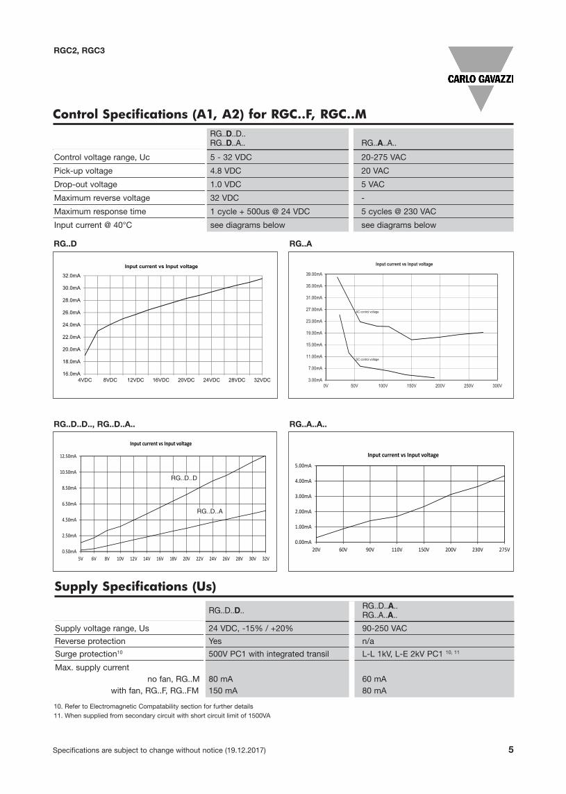
Control Specifications (A1, A2) for RGC..F, RGC..MRG..D..D..RG..D..A.. RG..A..A..
Control voltage range, Uc 5 - 32 VDC 20-275 VAC
Pick-up voltage 4.8 VDC 20 VAC
Drop-out voltage 1.0 VDC 5 VAC
Maximum reverse voltage 32 VDC -
Maximum response time 1 cycle + 500us @ 24 VDC 5 cycles @ 230 VAC
Input current @ 40°C see diagrams below see diagrams below
RG..D RG..A
10. Refer to Electromagnetic Compatability section for further details 11. When supplied from secondary circuit with short circuit limit of 1500VA
Supply Specifications (Us)
RG..D..D.. RG..D..A..RG..A..A..
Supply voltage range, Us 24 VDC, -15% / +20% 90-250 VAC
Reverse protection Yes n/a
Surge protection10 500V PC1 with integrated transil L-L 1kV, L-E 2kV PC1 10, 11
Max. supply currentno fan, RG..M
with fan, RG..F, RG..FM 80 mA150 mA
60 mA80 mA
RG..D..D.., RG..D..A.. RG..A..A..
0.50mA
2.50mA
4.50mA
6.50mA
8.50mA
10.50mA
12.50mA
5V 6V 8V 10V 12V 14V 16V 18V 20V 22V 24V 26V 28V 30V 32V
Input current vs Input voltage
0.00mA
1.00mA
2.00mA
3.00mA
4.00mA
5.00mA
20V 60V 90V 110V 150V 200V 230V 275V
Input current vs Input voltage
RG..D..D
RG..D..A

6 Specifications are subject to change without notice (19.12.2017)
RGC2, RGC3
Alarm Specifications (12, 14, 11)
RG..FRG..M
Output type EMR, 1 Form C (SPDT)Normally closed (12-11)Normally open (14-11)
Contact rating 2A @ 250VAC / 30VDCIsolation
between open contacts 1000VAC
Auxiliary Output Specifications (22, 24, 21)
12: Refer to Derating Curve for Auxliary Output rating @ higher operating temperature
Output type
RG..D..D..RG..D..A.. RG..A..A..
PNP darlington, Normally closed (22-21)
NPN darlington, Normally open (24-21)
Triac, Normally closed (22-21)
Triac, Normally open (24-21)
Rated voltage 24VDC +/-20% 90-250VAC
On-state voltage drop Typical 4VDC < 2VAC
Blocking voltage - 800Vp
Maximum current rating 50mADC 1AAC @ 25°C12
Delay from SSR output switching toauxiliary output
5 cycles 5 cycles
Output Power Dissipation
RGC3..10
14
12
11
RGC2..10

0
10
20
30
40
50
60
70
80
90
20 25 30 35 40 45 50 55 60 65 70 75 80
Load
Cur
rent
per
pol
e in
AA
C
Surrounding Ambient Temperature in °C
RGC2..75..DFRGC2..75..DFMRGC2..75..AF, AFM (up to 60°C)
RGC2..40RGC2..40..DMRGC2..40..AM (up to 60°C)
RGC2..25RGC2..25..DMRGC2..25..AM (up to 60°C)
RGC2..10(max. 9AAC for VDE)
Specifications are subject to change without notice (19.12.2017) 7
RGC2, RGC3
Current Derating
RGC2
RGC3
0
10
20
30
40
50
60
70
80
20 25 30 35 40 45 50 55 60 65 70 75 80
Load
Cur
rent
per
pol
e in
AA
C
Surrounding Ambient Temperature in °C
RGC3..65DF, DFM
RGC3..65AF, AFM
RGC3..40..DFRGC3..40..AF (up to 60°C)
RGC3..30RGC3..30..DMRGC3..30..AM (up to 60°C)
RGC3..25RGC3..25..DMRGC3..25..AM (up to 60°C)
RGC3..20RGC3..20..DMRGC3..20..AM (up to 60°C)
RGC3..10(max. 9AAC for VDE)

8 Specifications are subject to change without notice (19.12.2017)
RGC2, RGC3
Derating Vs. Spacing Curves
Temp Current Temp Current
0°C 26.8A 0°C 32.0A
25°C 26.8A 25°C 32.0A
80°C 9.5A 80°C 12.5A
0mm 10mm
0
5
10
15
20
25
30
35
20 30 40 50 60 70 80
Load
Cur
rent
per
pol
e in
AA
C
Surrounding Ambient Temperature in °C
10mm
0mm
A in
0
2
4
6
8
10
12
0 10 20 30 40 50 60 70 80
Load
Cur
rent
per
pol
e in
AAC
Surrounding Ambient Temperature in °C
Standalone
20mm andover
10mm
0mm
0
10
20
30
40
50
60
20 30 40 50 60 70 80
Load
Cur
rent
per
pol
e in
AA
C
Surrounding Ambient Temperature in °C
10mm
0mm
R
A in
0
10
20
30
40
50
60
70
80
90
20 30 40 50 60 70
Load
Cur
rent
per
pol
e in
AA
C
Surrounding Ambient Temperature in °C
10mm
0mm
T
A in
RGC2..10
RGC2..25
RGC2..40
RGC2..75
Note: RGC2A..AM up to 60oC
Note: RGC2A..AM up to 60oC
Note: RGC2A..AM up to 60oC
Note: RGC2A..AF, AFM up to 60oC

Specifications are subject to change without notice (19.12.2017) 9
RGC2, RGC3
Derating Vs. Spacing Curves - cont.
0
2
4
6
8
10
12
0 10 20 30 40 50 60 70 80
Load
Cur
rent
per
pol
e in
AAC
Surrounding Ambient Temperature in °C
Standalone
20mm andover
10mm
0mm
RGC2..10
0
2
4
6
8
10
12
0 10 20 30 40 50 60 70 80
Load
Cur
rent
per
pol
e in
AAC
Surrounding Ambient Temperature in °C
Standalone
20mm andover
10mm
0mm
RGC3..10
Temp Current Temp Current
0°C 26.8A 0°C 32.0A
25°C 26.8A 25°C 32.0A
80°C 9.5A 80°C 12.5A
RGC2_25
0mm 10mm
0
5
10
15
20
25
30
35
20 30 40 50 60 70 80
Load
Cur
rent
per
pol
e in
AA
C
Surrounding Ambient Temperature in °C
RGC2..25
10mm
0mm
0
10
20
30
40
50
60
20 30 40 50 60 70 80
Load
Cur
rent
per
pol
e in
AA
C
Surrounding Ambient Temperature in °C
RGC2..40
10mm
0mm
RGC2_75
0
10
20
30
40
50
60
70
80
90
20 30 40 50 60 70
Load
Cur
rent
per
pol
e in
AA
C
Surrounding Ambient Temperature in °C
RGC2..75
10mm
0mm
Temp Current Temp Current Temp Current
0°C 14.3A 0°C 19.5A 0°C 25.0A
25°C 14.3A 25°C 19.5A 25°C 25.0A
40°C 9.8A 40°C 15.5A 40°C 20.0A
70°C 3.0A 70°C 8.0A 60°C 15.0A
80°C 0.0A 80°C 5.0A 80°C 10.0A
RGC3_20
0mm 10mm 30mm
0
5
10
15
20
25
30
20 30 40 50 60 70 80
Load
Cur
rent
per
pol
e in
AA
C
Surrounding Ambient Temperature in °C
RGC3..20
30mm
10mm
0mm
Temp Current Temp Current Temp Current
0°C 14.3A 0°C 19.5A 0°C 25.0A
25°C 14.3A 25°C 19.5A 25°C 25.0A
40°C 9.8A 40°C 15.5A 40°C 20.0A
70°C 3.0A 70°C 8.0A 60°C 15.0A
80°C 0.0A 80°C 5.0A 80°C 10.0A
RGC3_20
0mm 10mm 30mm
0
5
10
15
20
25
30
35
20 30 40 50 60 70 80
Load
Cur
rent
per
pol
e in
AA
C
Surrounding Ambient Temperature in °C
RGC3..25
20mm
0mm
Temp Current Temp Current0°C 33.5A 0°C 37.0A
25°C 33.5A 25°C 37.0A40°C 27.0A 40°C 30.0A80°C 12.5A 80°C 17.5A
RGC3_300mm 20mm
0
5
10
15
20
25
30
35
40
20 30 40 50 60 70 80
Load
Cur
rent
per
pol
e in
AA
C
Surrounding Ambient Temperature in °C
RGC3..30
20mm
0mm
Temp Current Temp Current0°C 33.5A 0°C 37.0A
25°C 33.5A 25°C 37.0A40°C 27.0A 40°C 30.0A80°C 12.5A 80°C 17.5A
0mm 20mmRGC3_30
05
1015202530354045
20 30 40 50 60 70
Load
Cur
rent
per
pol
e in
AA
C
Surrounding Ambient Temperature in °C
RGC3..40
10mm
0mm
Temp Current Temp Current0°C 33.5A 0°C 37.0A
25°C 33.5A 25°C 37.0A40°C 27.0A 40°C 30.0A80°C 12.5A 80°C 17.5A
RGC3_300mm 20mm
0
10
20
30
40
50
60
70
80
20 30 40 50 60 70 80
Load
Cur
rent
per
pol
e in
AA
C
Surrounding Ambient Temp.erature in °C
RGC3..65DF, DFM
10mm
0mm
Temp Current Temp Current0°C 33.5A 0°C 37.0A
25°C 33.5A 25°C 37.0A40°C 27.0A 40°C 30.0A80°C 12.5A 80°C 17.5A
RGC3_300mm 20mm
01020304050607080
20 30 40 50 60 70
Load
Cur
rent
per
pol
e in
AA
C
Surrounding Ambient Temperature in °C
RGC3..65AF, AFM
10mm
0mm
Temp Current Temp Current
0°C 26.8A 0°C 32.0A
25°C 26.8A 25°C 32.0A
80°C 9.5A 80°C 12.5A
RGC2_25
0mm 10mm
0
5
10
15
20
25
30
35
20 30 40 50 60 70 80
Load
Cur
rent
per
pol
e in
AA
C
Surrounding Ambient Temperature in °C
RGC2..25
10mm
0mm
0
10
20
30
40
50
60
20 30 40 50 60 70 80
Load
Cur
rent
per
pol
e in
AA
C
Surrounding Ambient Temperature in °C
RGC2..40
10mm
0mm
RGC2_75
0
10
20
30
40
50
60
70
80
90
20 30 40 50 60 70
Load
Cur
rent
per
pol
e in
AA
C
Surrounding Ambient Temperature in °C
RGC2..75
10mm
0mm
Temp Current Temp Current Temp Current
0°C 14.3A 0°C 19.5A 0°C 25.0A
25°C 14.3A 25°C 19.5A 25°C 25.0A
40°C 9.8A 40°C 15.5A 40°C 20.0A
70°C 3.0A 70°C 8.0A 60°C 15.0A
80°C 0.0A 80°C 5.0A 80°C 10.0A
RGC3_20
0mm 10mm 30mm
0
5
10
15
20
25
30
20 30 40 50 60 70 80Lo
ad C
urre
nt p
er p
ole
in A
AC
Surrounding Ambient Temperature in °C
RGC3..20
30mm
10mm
0mm
Temp Current Temp Current Temp Current
0°C 14.3A 0°C 19.5A 0°C 25.0A
25°C 14.3A 25°C 19.5A 25°C 25.0A
40°C 9.8A 40°C 15.5A 40°C 20.0A
70°C 3.0A 70°C 8.0A 60°C 15.0A
80°C 0.0A 80°C 5.0A 80°C 10.0A
RGC3_20
0mm 10mm 30mm
0
5
10
15
20
25
30
35
20 30 40 50 60 70 80
Load
Cur
rent
per
pol
e in
AA
C
Surrounding Ambient Temperature in °C
RGC3..25
20mm
0mm
Temp Current Temp Current0°C 33.5A 0°C 37.0A
25°C 33.5A 25°C 37.0A40°C 27.0A 40°C 30.0A80°C 12.5A 80°C 17.5A
RGC3_300mm 20mm
0
5
10
15
20
25
30
35
40
20 30 40 50 60 70 80
Load
Cur
rent
per
pol
e in
AA
C
Surrounding Ambient Temperature in °C
RGC3..30
20mm
0mm
Temp Current Temp Current0°C 33.5A 0°C 37.0A
25°C 33.5A 25°C 37.0A40°C 27.0A 40°C 30.0A80°C 12.5A 80°C 17.5A
0mm 20mmRGC3_30
05
1015202530354045
20 30 40 50 60 70
Load
Cur
rent
per
pol
e in
AA
C
Surrounding Ambient Temperature in °C
RGC3..40
10mm
0mm
Temp Current Temp Current0°C 33.5A 0°C 37.0A
25°C 33.5A 25°C 37.0A40°C 27.0A 40°C 30.0A80°C 12.5A 80°C 17.5A
RGC3_300mm 20mm
0
10
20
30
40
50
60
70
80
20 30 40 50 60 70 80
Load
Cur
rent
per
pol
e in
AA
C
Surrounding Ambient Temp.erature in °C
RGC3..65DF, DFM
10mm
0mm
Temp Current Temp Current0°C 33.5A 0°C 37.0A
25°C 33.5A 25°C 37.0A40°C 27.0A 40°C 30.0A80°C 12.5A 80°C 17.5A
RGC3_300mm 20mm
01020304050607080
20 30 40 50 60 70
Load
Cur
rent
per
pol
e in
AA
C
Surrounding Ambient Temperature in °C
RGC3..65AF, AFM
10mm
0mm
RGC3..10
RGC3..20
RGC3..25
RGC3..30
Note: RGC3A..AM up to 60oC
Note: RGC3A..AM up to 60oC
Note: RGC3A..AM up to 60oC

10 Specifications are subject to change without notice (19.12.2017)
RGC2, RGC3
Derating Vs. Spacing Curves - cont.
Temp Current Temp Current0°C 33.5A 0°C 37.0A
25°C 33.5A 25°C 37.0A40°C 27.0A 40°C 30.0A80°C 12.5A 80°C 17.5A
0mm 20mmRGC3_30
05
1015202530354045
20 30 40 50 60 70
Load
Cur
rent
per
pol
e in
AA
C
Surrounding Ambient Temperature in °C
RGC3..40
10mm
0mm
A in
Temp Current Temp Current0°C 33.5A 0°C 37.0A
25°C 33.5A 25°C 37.0A40°C 27.0A 40°C 30.0A80°C 12.5A 80°C 17.5A
RGC3_300mm 20mm
0
10
20
30
40
50
60
70
80
Loa d
Cur
rent
per
pol
e in
AA
C
Surrounding Ambient Temperature in °C
RGC3..65DF, DFM
10mm
0mm
Te mp Current Temp Current0 °C 33.5A 0°C 37.0A
25 °C 33.5A 25°C 37.0A40 °C 27.0A 40°C 30.0A80 °C 12.5A 80°C 17.5A
RGC3_300mm 20mm
01020304050607080
L oa d
Cur
rent
per
pol
e in
AA
C
Surrounding Ambient Temperature in °C
RGC3..65AF, AFM
10mm
0mm
Note: RGC3..AF up to 60 oC

Note:• Control input lines must be installed together to maintain products susceptibility to Radio Frequency Interference.• Use of AC solid state relays may according to the application and the load current, cause conducted radio interferences. Use of mains filters may be
necessary for cases where the user must meet E.M.C requirements. The capacitor values given inside the filtering specification tables should be taken only as indications, the filter attenuation will depend on the final application.
• This product has been designed for Class A equipment. Use of this product in domestic environments may cause radio interference, in which case the user may be required to employ additional mitigation methods.
• Surge tests on RGC..A, RGC..A..A.. models were carried out with the signal line impedence network. In case the line impedance is less than 40Ω, it is suggested that AC supply is provided through a secondary circuit where the short circuit limit between conductors or between conductors and ground is 1500VA or less.
* For conformance to EN/IEC 61000-6-4, an external capacitor class X1, 220nF, 275VAC is to be connected across the input control lines A1-A2 for AC control versions.
** With external varistor 275V (S05K275) Type 2 connected between terminals 22 - 21 or terminals 24 - 21.
- Performance Criteria 1 (Performance Criteria A): No degradation of performance or loss of function is allowed when the product is operated as intended.- Performance Criteria 2 (Performance Criteria B): During the test, degredation of performance or partial loss of function is allowed. However, when the test is complete the product should return operating as intended by itself.
- Performance Criteria 3 (Performance Criteria C): Temporary loss of function is allowed, provided the function can be restored by manual operation of the control.
13: applicable only to RGC...10
Specifications are subject to change without notice (19.12.2017) 11
Agency Approvals and Conformance
Conformance EN/IEC 60947-4-2EN/IEC 60947-4-3
Short Circuit Current rating 100kArms, UL508
Agency Approvals UL Listed (E172877), UL508cUL Listed (E172877), C22.2 No.14-13CCC, GB/T 14048.5-2008(IEC 60947-5-1)
Electromagnetic Compatibility
EMC immunity EN 60947-4-3
Electrostatic discharge (ESD)immunity EN/IEC 61000-4-2Air discharge, 8kV Performance Criteria 2Contact, 4kV Performance Criteria 2
Electrical fast transient(Burst) immunity EN/IEC 61000-4-4Output: 2kV, 5kHz Performance Criteria 1Input: 1kV, 5kHz Performance Criteria 1Signal: 1kV, 5kHz RGC..M Performance Criteria 1
Electrical surge immunity EN/IEC 61000-4-5Output, line to line, 1kV Performance Criteria 1Output, line to earth, 2kV Performance Criteria 1Input, line to line, 1kV (A1, A2) Performance Criteria 2Input, line to earth, 2kV (A1, A2) Performance Criteria 2Signal, line to line, 500V (Us, 21, 22, 24)
RGC..D..D Performance Criteria 1Signal, line to line, 1kV (Us, 21, 22, 24)
RGC..D..A Performance Criteria 1**RGC..A..A Performance Criteria 1**
Signal, line to earth, 500V (Us, 21, 22, 24)RGC..D..D Performance Criteria 1
Signal, line to earth, 1kV (Us, 21, 22, 24)RGC..D..A Performance Criteria 1RGC..A..A Performance Criteria 1
11, 12, 14, line to line, 1kV Performance Criteria 111, 12, 14, line to earth, 2kV Performance Criteria 1
Radiated radio frequency immunity EN/IEC 61000-4-310V/m, 80 - 1000MHz Performance Criteria 110V/m, 1.4 - 2.0GHz Performance Criteria 110V/m, 2.0 - 2.7GHz Performance Criteria 1
Conducted radio frequence immunity EN/IEC 61000-4-610V/m, 0.15 - 80MHz Performance Criteria1
Voltage dips immunity EN/IEC 61000-4-110% for 0.5/1cycle Performance Criteria 240% for 10 cycles Performance Criteria 270% for 25 cycles Performance Criteria 280% for 250 cycles Performance Criteria 2
Voltage interruptionsimmunity EN/IEC 61000-4-110% for 5000ms Performance Criteria 2
Radio interference fieldemission (radiated) EN/IEC 55011
30-1000MHz Class A (Industrial)
EMC emission EN 60947-4-3*
Radio interference voltageemission (conducted) EN/IEC 55011
0.15-30MHz Class A (Industrial) with filters - see filter information
RGC2, RGC3
s
RGC...10 VDE 0660-117, (DIN EN 60947-4-2)13VDE 0700-1 (DIN EN 60335-1)13
12 Specifications are subject to change without notice (19.12.2017)
RGC2, RGC3
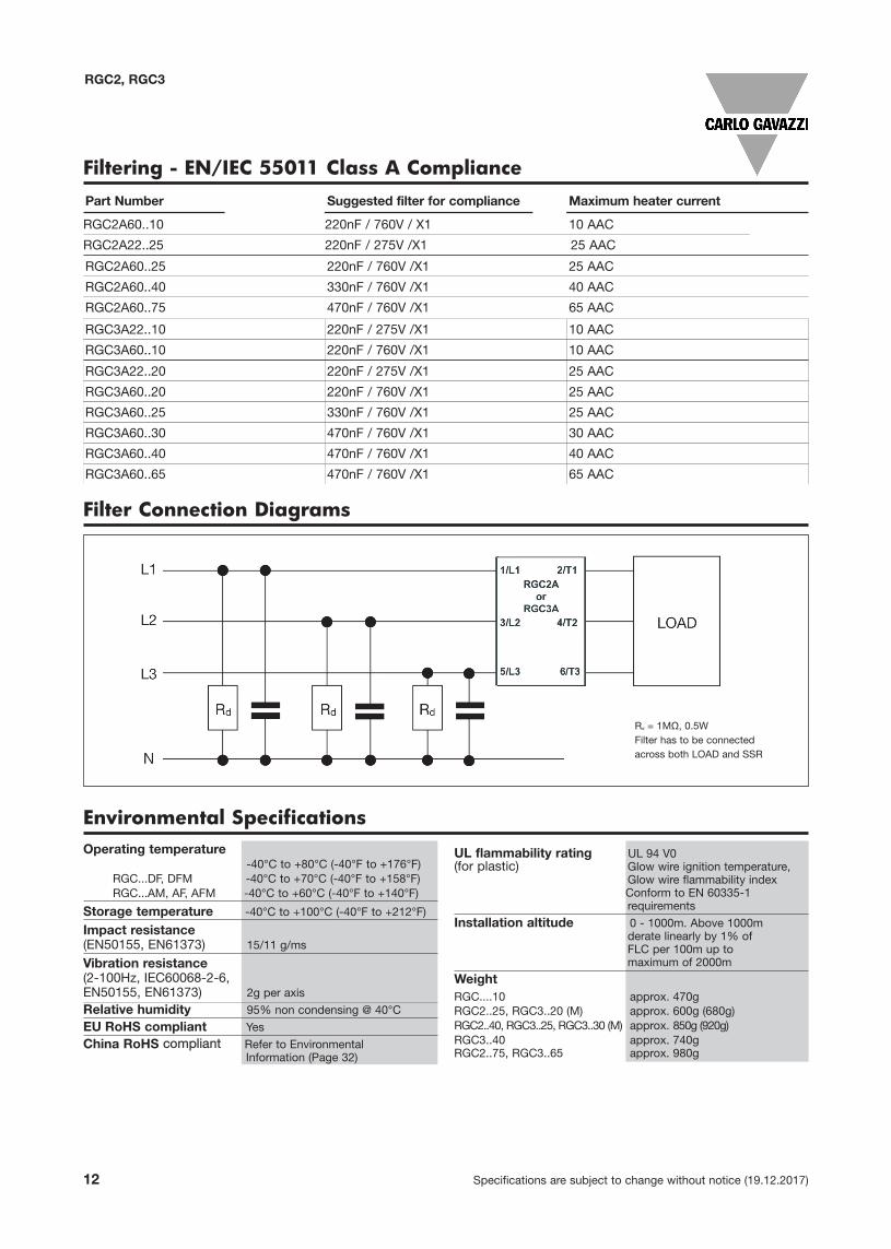
Filtering - EN/IEC 55011 Class A CompliancePart Number Suggested filter for compliance Maximum heater current
RGC2A60..10 220nF / 760V / X1 10 AAC
RGC2A22..25 220nF / 275V /X1 25 AAC
RGC2A60..25 220nF / 760V /X1 25 AAC
RGC2A60..40 330nF / 760V /X1 40 AAC
RGC2A60..75 470nF / 760V /X1 65 AAC
RGC3A22..20 220nF / 275V /X1 25 AAC
RGC3A60..20 220nF / 760V /X1 25 AAC
RGC3A60..25 330nF / 760V /X1 25 AAC
RGC3A60..30 470nF / 760V /X1 30 AAC
RGC3A60..40 470nF / 760V /X1 40 AAC
RGC3A60..65 470nF / 760V /X1 65 AAC
RGC3A22..10 220nF / 275V /X1 10 AAC
RGC3A60..10 220nF / 760V /X1 10 AAC
Filter Connection Diagrams
Rd = 1MΩ, 0.5WFilter has to be connectedacross both LOAD and SSR
Environmental SpecificationsOperating temperature
-40°C to +80°C (-40°F to +176°F)RGC...DF, DFM -40°C to +70°C (-40°F to +158°F)RGC...AM, AF, AFM -40°C to +60°C (-40°F to +140°F)
Storage temperature -40°C to +100°C (-40°F to +212°F)
Impact resistance(EN50155, EN61373) 15/11 g/ms
Vibration resistance(2-100Hz, IEC60068-2-6,EN50155, EN61373) 2g per axis
Relative humidity 95% non condensing @ 40°C
EU RoHS compliant Yes
China RoHS compliant Refer to Environmental Information (Page 32)
UL flammability rating UL 94 V0 (for plastic) Glow wire ignition temperature,
Glow wire flammability index Conform to EN 60335-1 requirements
Installation altitude 0 - 1000m. Above 1000m derate linearly by 1% of FLC per 100m up to maximum of 2000m
WeightRGC....10 approx. 470gRGC2..25, RGC3..20 (M) approx. 600g (680g)RGC2..40, RGC3..25, RGC3..30 (M) approx. 850g (920g)RGC3..40 approx. 740gRGC2..75, RGC3..65 approx. 980g

Specifications are subject to change without notice (19.12.2017) 13
RGC2, RGC3
Terminal Layout
RGC2..10, RGC2..25, RGC2..40RGC3..10, RGC3..20, RGC3..25, RGC3..30
RGC2..25..DM, RGC2..40..DMRGC3..20..DM, RGC3..25..DM, RGC3..30..DM
RGC2..25..AM, RGC2..40..AMRGC3..20..AM, RGC3..25..AM, RGC3..30..AM
Terminals labelling:1/L1, 2/L2, 3/L3: Mains connections
2/T1, 4/T2, 6/T3: Load connections
A1(+): Positive control signal
A2(-): Control ground
Us(+): External supply positive signal
Us(-): External supply ground
Us(~): AC external supply
Uf(+): Fan supply positive signal
(no connection required by end user)
Uf(-): Fan supply ground
(no connection required by end user)
12: Alarm EMR, normally closed
14: Alarm EMR, normally open
11: Alarm EMR, common terminal
22: Auxiliary output, normally closed
24: Auxiliary output, normally open
21: Auxiliary output, common terminal
Connections to Uf+, Uf- are provided readily terminatedby manufacturer. However, in case of needed user inter-vention on terminals Uf+, Uf- for the RGC..A..AF andRGC..A..AFM models, the mains supply has to be tur-ned off first to avoid risk of electrical shock.
RGC2..75..DFRGC3..40..DF, RGC3..65..DF
RGC2..75..AFRGC3..40..AF, RGC3..65..AF
RGC2..75..DFMRGC3..65..DFM
RGC2..75..AFMRGC3..65..AFM
14 Specifications are subject to change without notice (19.12.2017)
RGC2, RGC3
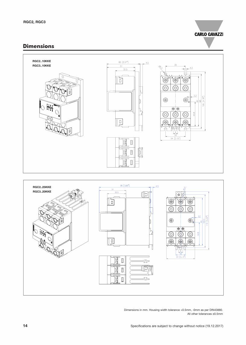
Dimensions
RGC2..25KKE
RGC3..20KKE
RGC2..10KKE
RGC3..10KKE
Dimensions in mm. Housing width tolerance +0.5mm, -0mm as per DIN43880. All other tolerances ±0.5mm

Specifications are subject to change without notice (19.12.2017) 15
RGC2, RGC3
Dimensions
RGC2..25GKE..M
RGC3..20GKE..M
Dimensions in mm. Housing width tolerance +0.5mm, -0mm as per DIN43880. All other tolerances ±0.5mm
RGC3..25KKE
16 Specifications are subject to change without notice (19.12.2017)
RGC2, RGC3
Dimensions in mm. Housing width tolerance +0.5mm, -0mm as per DIN43880. All other tolerances ±0.5mm
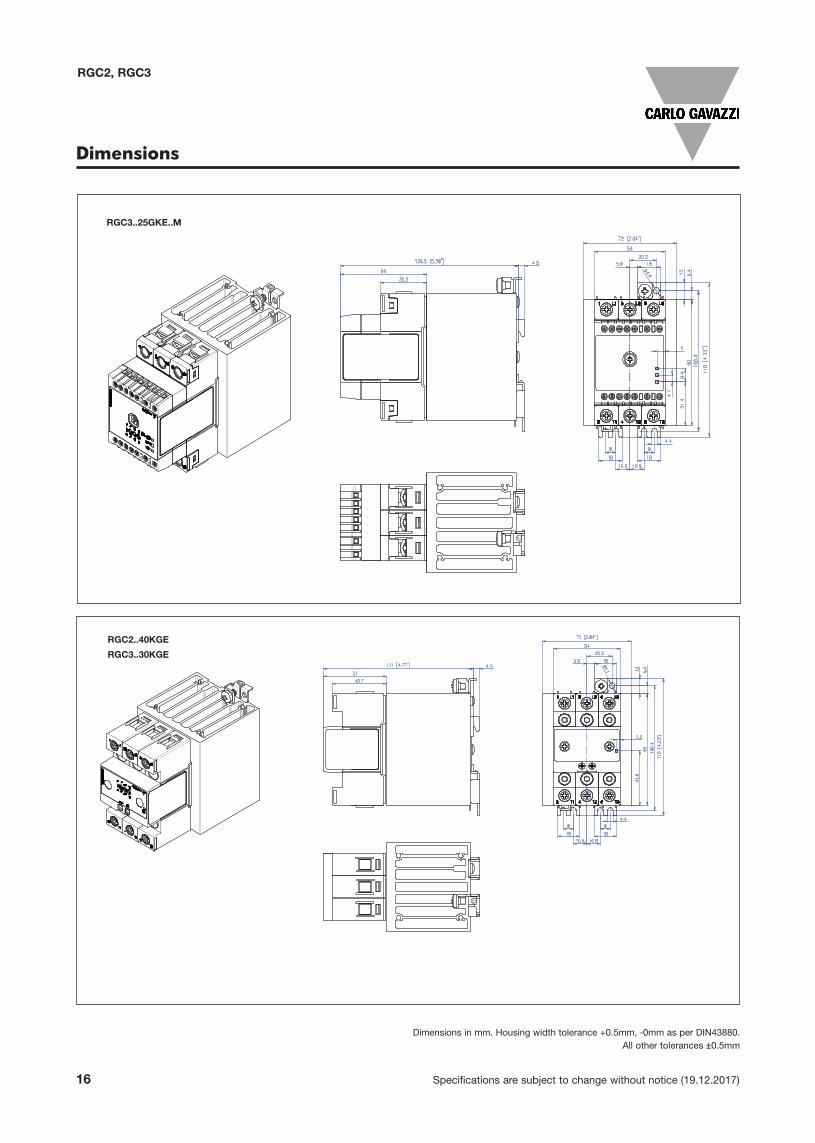
Dimensions
RGC3..25GKE..M
RGC2..40KGE
RGC3..30KGE

Specifications are subject to change without notice (19.12.2017) 17
RGC2, RGC3
Dimensions
Dimensions in mm. Housing width tolerance +0.5mm, -0mm as per DIN43880. All other tolerances ±0.5mm
RGC2..40GGE..M
RGC3..30GGE..M
RGC3..40GGE..F

18 Specifications are subject to change without notice (19.12.2017)
RGC2, RGC3
RGC2..75GGE..
RGC3..65GGE..
Dimensions
Dimensions in mm. Housing width tolerance +0.5mm, -0mm as per DIN43880. All other tolerances ±0.5mm

Specifications are subject to change without notice (19.12.2017) 19
RGC2, RGC3
Stripping length (X) 8 mm
Connection type M3 screw with captivated washer M3 screw with box clamp
Rigid (solid & stranded)
UL/cUL rated data
2x 0.5 - 2.5 mm2
2x 18 - 12 AWG1x 0.5 - 2.5 mm2
1x 18 - 12 AWG1x 1.0 - 2.5 mm2
1x 18 - 12 AWG
Flexible with endsleeve
2x 0.5 - 2.5 mm2
2x 18 - 12 AWG1x 0.5 - 2.5 mm2
1x 18 - 12 AWG
1x 0.5 - 2.5 mm2
1x 20 - 12 AWG
Torque specificationPozidriv 1UL: 0.5Nm (4.4 lb-in)IEC: 0.5-0.6Nm (4.4-5.3 lb-in)
Pozidriv 1UL: 0.5Nm (4.4 lb-in)IEC: 0.4-0.5Nm (3.5-4.4 lb-in)
CONTROL CONNECTIONS
Use 75°C copper (Cu) conductors
A1, A2 A1, A2, Us, Uf, 11, 12, 14, 21, 22, 24
Connection Specifications
Stripping length (X) 12mm 11mm
Connection type M4 screw with captivated washer M5 screw with box clamp
Rigid (solid & stranded)
UL/cUL rated data
2x 2.5 - 6.0 mm2
2x 14 - 10 AWG1x 2.5 - 6.0 mm2
1x 14 - 10 AWG1x 2.5 - 25 mm2
1x 14 - 3 AWG
Flexible with endsleeve
2x 1.0 - 2.5 mm2
2x 2.5 - 4.0 mm2
2x 18 - 14 AWG2x 14 - 12 AWG
1x 1.0 - 4.0 mm2
1x 18 - 12 AWG
1x 2.5 - 16 mm2
1x 14 - 6 AWG
Flexible without endsleeve
2x 1.0 - 2.5 mm2
2x 2.5 - 6.0 mm2
2x 18 - 14 AWG2x 14 - 10 AWG
1x 1.0 - 6.0 mm2
1x 18 - 10 AWG
1x 4.0 - 25 mm2
1x 12 - 3 AWG
Torque specificationPozidriv 2UL: 2Nm (17.7 lb-in)IEC: 1.5-2.0Nm (13.3-17.7 lb-in)
Pozidriv 2UL: 2.5Nm (22 lb-in)IEC: 2.5-3.0Nm (22-26.6 lb-in)
Aperture fortermination lug
12.3mm n/a
Protective Earth (PE)connection
M5, 1.5Nm (13.3 lb-in)
Not provided with SSR. PE connection required when product is intended to be used in Class 1 applicationsaccording to EN/IEC 61140
POWER CONNECTIONS
Use 75°C copper (Cu) conductors
1/L1, 3/L2, 5/L3, 2/T1, 4/T2, 6/T3
RG..KKE, RG..GKE RG..KGE, RG..GGE
RG..KKE, RG..KGE RG..GKE, RG..GGE
8mm

20 Specifications are subject to change without notice (19.12.2017)
RGC2, RGC3
Connection Diagram
L1L2L3NPE
A1 + A2-
1 L1 3 L2 5 L3
2 T1 4 T2 6 T3
RGC3
RGC2
Motor3 ~
*
* *
2 4 6
2 4 6
2 4 6
2 4 6
2 4 6
2 4 6
N
2 3 4 5 6 1
* Not suitable for use with RGC...M versions

Specifications are subject to change without notice (19.12.2017) 21
RGC2, RGC3
Connection Configuration for Auxiliary OutputVersions: RGC..D..DM, RGC..D..DFMAuxiliary output signal 24VDC, 50mA; DC control, Uc (5-32VDC); DC external supply, Us (24VDC)
to PLC
Gnd
pull downresistor
22 NC
AUX O/P
24 NO
AUX O/
Uf- FAN
Uf+ FAN
+24Vdc
24VDC
P
21 COM
AUX O/P
A
Us- SUPPLY
Us+ SUPPLY
5
12 NC
ALARM
14 NO
ALARM
A2- CONTRO
5 32VDC
11 COM
ALARM
OL A1+
CONTROL
Connection of normally open auxiliary output (24-21) in a ‘pnp’style
Connection of normally open auxiliary output (24-21) in an ‘npn’style
Gnd
22 NC
AUX O/P
24 NO
AUX O/
Uf- FAN
Uf+ FAN
to PLC
+24Vdc
pull upresistor
24VDC
P
21 COM
AUX O/P
A
Us- SUPPLY
Us+ SUPPLY
5
12 NC
ALARM
14 NO
ALARM
A2- CONTRO
5 32VDC
11 COM
ALARM
OL A1+
CONTROL
Versions: RGC..D..AM, RGC..D..AFMAuxiliary output signal 24VDC, 50mA; DC control, Uc (5-32VDC); AC external supply, Us (90-250VAC)
Connection of normally open auxiliary output (24-21) in a ‘pnp’style
Connection of normally open auxiliary output (24-21) in an ‘npn’style
to PLC
Gnd
pull downresistor
22 NC
AUX O/P
24 NO
AUX O/
Uf- FAN
Uf+ FAN
+24Vdc
90 250
P
21 COM
AUX O/P
A
Us~ SUPPLY
50VAC
12 NC
ALARM
14 NO
ALARM
A2- CONTRO
Us~ SUPPLY
5 32VDC
11 COM
ALARM
OL A1+
CONTROL
Gnd
22 NC
AUX O/P
24 NO
AUX O/
Uf- FAN
Uf+ FAN
to PLC
+24Vdc
pull upresistor
90 250
P
21 COM
AUX O/P
A
Us~ SUPPLY
50VAC
12 NC
ALARM
14 NO
ALARM
A2- CONTRO
Us~ SUPPLY
5 32VDC
11 COM
ALARM
OL A1+
CONTROL

22 Specifications are subject to change without notice (19.12.2017)
RGC2, RGC3
Conection Configuration for Auxiliary OutputVersions: RGC..A..AM, RGC..A..AFMAuxiliary output signal 90-250VAC, max. 1A @ 25oC; AC control, Uc (20-275VAC); AC external supply, Us (90-250VAC)
90 – 2
Load
22 NC
AUX O/P
24 NO
AUX O/
Uf- FAN
Uf+ FAN
250VAC
90 250
P
21 COM
AUX O/P
A
Us~ SUPPLY
200VAC
12 NC
ALARM
14 NO
ALARM
A2- CONTRO
Us~ SUPPLY
0 275VAC
11 COM
ALARM
OL A1+
CONTROL
Connection of normally open auxiliary output (24-21) to an AC load
Note: In relation to the auxiliary output terminals 22, 24, 21; it is not possible to connect all 3 terminals to the auxiliary circuit. Preference shall be given to either a normally open (24-21) or normally closed (22-21) contact. The respective terminations shall be choosen and configured accordingly.

Specifications are subject to change without notice (19.12.2017) 23
RGC2, RGC3
RGC..M Mode of Operation
The RGC..M versions are suitable only for use with resistive loads.
The ‘M’ suffix versions integrate monitoring circuitry that can detect the status of the Mains, Load, and Solid State Relay(SSR) status. The fault conditions that can be detected with the RGC..M include: - Mains loss- Load loss- SSR open circuit - SSR short circuit- SSR over temperature
An external supply, 24VDC or 90-250VAC, selectable through part no. configuration, is required for the operation of theRGC..M models. In the case of a fault condition, an EMR alarm output is available through terminals 11, 12, 14 for remoteindication. Alarm visual indication is provided by a flashing red LED. The flash rate of the red LED gives an indication of thetype of alarm condition detected.
The RGC..M is also equipped with an auxiliary output which operates in synchronisation with the output of the SSR. Thiselectronic auxiliary output with normally open or normally closed user selectable contacts is available through terminals 21,22, 24. A yellow LED gives indication of the SSR output status.
Mains Loss:
The mains loss alarm is issued if the mains voltage is missing from either terminals L1, L2 or L3 for more than 1 second. Thisalarm type is indicated by 2 flashes of the red LED. The alarm resets automatically once the mains voltage is restored andis present on terminals L1, L2 and/or L3 for more than 1 second.
Mains Supply (L1, L2, L3)
Load Supply (T1, T2, T3)
Load Current
Auxiliary Output, NO (21-24)
Auxiliary Output, NC (21-22)
Supply Voltage (Us)
Control Voltage (A1, A2)
Green LED (Control & Supply)
Yellow LED (Load status)
Red LED (Alarm LED)
Alarm Output, NO (11-14)
Alarm Output, NC (11-12)
Supply Voltage (Us)
Loss
Supply Voltage (Us)
Loss
Normal Opera!on
SSR ON
Normal Opera!on SSR OFF
Normal Opera!on
SSR ON
Mains Loss Detec!on ( > 1s)

24 Specifications are subject to change without notice (19.12.2017)
RGC2, RGC3
Mains Supply (L1, L2, L3)
Load Supply (T1, T2, T3)
Load Current
Auxiliary Output, NO (21-24)
Auxiliary Output, NC (21-22)
Supply Voltage (Us)
Control Voltage (A1, A2)
Green LED (Control & Supply)
Yellow LED (Load status)
Red LED (Alarm LED)
Alarm Output, NO (11-14)
Alarm Output, NC (11-12)
Control OFF during Load Loss status
Normal
SSR ON
Load restored
Supply Voltage (Us)
Loss
Normal
SSR OFF
Normal
SSR ON
Load Loss ( > 120ms)
during control ON
Load Loss:
Detection of load loss is possible both with control voltage ON and control voltage OFF. This alarm is issued in the absenceof a load termination or an open load on terminals T1, T2 and/or T3 exceeding 120ms. Upon detection of this alarm, the SSRoutput is switched OFF. This alarm type is indicated by 3 flashes of the red LED. The fault condition is automatically restoredonce the fault is cleared. As long as the load loss condition is present and an alarm is issued accordingly, other alarmconditions occuring when load loss is still present are ignored. For example, if a mains loss occurs during a load loss alarmcondition, such an alarm is not indicated until the load loss is cleared. Only once the load loss is cleared, the mains lossalarm is issued if still present.
RGC..M Mode of Operation (continued)
The load loss alarm is not restored automatically in the case of the loads having delta connection. The external supply, Usneeds to be re-setted (switched OFF and back ON) to clear the alarm signal.

Specifications are subject to change without notice (19.12.2017) 25
RGC2, RGC3
SSR Short Circuit:
This condition is detected when the SSR output remains ON for more than 250ms without control voltage. Upon this alarm,an attempt is made to switch OFF the SSR output but this may not be possible in case of a damaged SSR output(s). Alarmindication is given by 3 flashes of the red LED (same as the load loss alarm indication). In case of a self recovery, the SSRwill automatically reset.
During an SSR short circuit condition, the SSR output is ON unintentionally. In this case the auxiliary output does not workin synchronisation with the SSR output.
Mains Supply (L1, L2, L3)
Load Supply (T1, T2, T3)
Load Current
Auxiliary Output, NO (21-24)
Auxiliary Output, NC (21-22)
Supply Voltage (Us)
Control Voltage (A1, A2)
Green LED (Control & Supply)
Yellow LED (Load status)
Red LED (Alarm LED)
Alarm Output, NO (11-14)
Alarm Output, NC (11-12)
Normal
SSR OFF
Normal
SSR ON
SSR short circuit during control OFF
(>250ms)
RGC..M Mode of Operation (continued)

26 Specifications are subject to change without notice (19.12.2017)
RGC2, RGC3
SSR Open Circuit:
This alarm is issued when either one of the poles or all 3 poles do not switch ON within 250ms when control voltage isapplied. This alarm type is identified by 4 flashes of the red LED.
Example Condition 1:Once the open circuit alarm is issued it remains present for 1 minute as long as control voltage is ON. After 1 minute, anattempt to switch ON the SSR is made if control is ON. In case the open circuit condition is still present the alarm is issuedagain. In the case of an open circuit on only 1 pole the load will switch on 2 phases for 250ms until the open circuit conditionon the damaged pole is detected. As soon as the open circuit condition is detected, an alarm is issued and the SSR outputis switched OFF. This cycle will repeat for a count of 10 times as long as the control voltage is present. After 10 times nofurther switch re-attempts are made. It is necessary to reset the external supply (Us) to re-attempt a switch ON. In casefailure persists device is to be returned to factory.
Example Condition 2:Once the open circuit alarm is issued it remains present for 1 minute as long as control voltage is ON. If during this periodthe control voltage is switched OFF, the alarm is automatically cleared and the count indicated in Condition 1 is also set to0. If control voltage is re-applied and the open circuit condition is detected an alarm is issued accordingly. After 1 minute,an attempt to switch ON the SSR is made if control is still ON. This will continue for a count of 10 times as long as the controlvoltage is present. After 10 times no further switch re-attempts are made. It is necessary to reset the external supply (Us) tore-attempt a switch ON. In case failure persists device is to be returned to factory.
Mains Supply (L1, L2, L3)
Load Current, I1
Load Current, I2
Load Current, I3
Auxiliary Output, NO (21-24)
Auxiliary Output, NC (21-22)
Supply Voltage (Us)
Control Voltage (A1, A2)
Green LED (Control & Supply)
Yellow LED (Load status)
Red LED (Alarm LED) ……
Alarm Output, NO (11-14)
Alarm Output, NC (11-12)
Switch ON re-a!empt, open circuit
condi"on s"ll present
Switch ON, open circuit condi"on on pole L1-T1 (>250ms)
120ms ON
120ms ON
Condi"on noitidnoC1 2
SSR open circuit condi"on on pole
L1-T1 (>250ms)
120ms ON
120ms ON
Normal Opera"on SSR
OFF
Normal Opera"on SSR OFF
…
120ms ON
120ms ON
120ms ON
120ms ON
SSR open circuit condi"on on pole L1-T1
(>250ms)
1 minute 1 minute 1 minute
RGC..M Mode of Operation (continued)

Specifications are subject to change without notice (19.12.2017) 27
RGC2, RGC3
Mains Supply (L1, L2, L3)
Load Supply (T1, T2, T3)
Load Current
Auxiliary Output, NO (21-24)
Auxiliary Output, NC (21-22)
Supply Voltage (Us)
Control Voltage (A1, A2)
Green LED (Control & Supply)
Yellow LED (Load status)
Red LED (Alarm LED)
Alarm Output, NO (11-14)
Alarm Output, NC (11-12)
Over Temperature
cleared
Normal
SSR OFF
Normal
SSR ONOver Temperature
SSR Over Temperature:
The SSR is equipped with internal temperature monitoring to prevent SSR damage in case of overheating conditions. Upondetection of such a condition the SSR output is switched OFF and an alarm is issued accordingly. This alarm is visuallyindicated by the red LED which is fully ON. Once the temperature cools down, the alarm is cleared and if control is still ONan attempt to re-start the SSR is made.
RGC..M Mode of Operation (continued)

28 Specifications are subject to change without notice (19.12.2017)
RGC2, RGC3
Red LED Alarm Indications
Fan operation for versions with integrated fan
Flashes Fault
Load loss or SSR short circuit
Mains loss
SSR open circuit
SSR over temperature100%
4
3
2
0.5s
3s
3s
3s
0.5s
ALARM Signal onlyALARM Signal and FAN
START
FAN: ON
Is Chip temperature >
115°C ?
N
Y
Chip temperature <
85°C ?
N
Y
START
N
Y
N
YSSR output: OFFRed LED: ONAlarm Signal: ON
Y
N Chiptemperature <
80°C?
FAN: OFF
Chip temperature
limit reached?
SSR output: ONRed LED: OFFAlarm Signal: OFF
Chip temperature
limit reached?
SSR output: OFFRed LED: ONAlarm Signal: ON
START
FAN: ON
Is Chip temperature >
115°C ?
N
Y
Is Chip temperature <
85°C ?
N
Y
START
N
Y
N
YSSR output: OFFRed LED: ONAlarm Signal: ON
Y
N
Y
Chiptemperature <
80°C?
N
SSR output: ONRed LED: OFFAlarm Signal: OFFFAN: OFF
FAN: OFF
Chip temperature
limit reached?
SSR output: ONRed LED: OFFAlarm Signal: OFF
Is Chip temperature <
80°C?
Chip temperature
limit reached?
SSR output: OFFRed LED: ONAlarm Signal: ON

Specifications are subject to change without notice (19.12.2017) 29
RGC2, RGC3
14: Consult a Carlo Gavazzi sales representative for use of 70A class J fuses
Protection Co-ordination, Type 1 vs Type 2:
Type one protection implies that after a short circuit, the device under test will no longer be in a functioning state. In type 2 co-ordinationthe device under test will still be functional after the short circuit. In both cases, however the short circuit has to be interrupted. The fusebetween enclosure and supply shall not open. The door or cover of the enclosure shall not be blown open. There shall be no damage toconductors or terminals and the conductors shall not separate from terminals. There shall be no breakage or cracking of insulating basesto the extent that the integrity of the mounting of live parts is impaired. Discharge of parts or any risk of fire shall not occur.
The product variants listed in the table hereunder are suitable for use on a circuit capable of delivering not more than 100,000A msSymmetrical Amperes. 600Volts maximum when protected by fuses. Tests at 100,000A were performed with Class J fuses, fast acting;please refer to the tables below for maximum. Tests with Class J fuses are representative of Class CC fuses.
Short Circuit Protection
Part No.Max. fusesize [A]
ClassShort circuit current
[kArms]Voltage [VAC]
RGC2..10
RGC2..25
30 J or CC 100 Max. 600
30 J or CC 100 Max. 600
RGC2..40 40 J 100 Max. 600
RGC2..75 6014 J 100 Max. 600
RGC3..10
RGC3..20
30 J or CC 100 Max. 600
30 J or CC 100 Max. 600
RGC3..25 30 J or CC 100 Max. 600
RGC3..30 40 J 100 Max. 600
RGC3..40 40 J 100 Max. 600
RGC3..65 6014 J 100 Max. 600
Co-ordination type 1 (UL508)
Installation Instructions
Y2 =100mm
Y1 = 50mm
50mm
X = 20mm20mm20mm
Mounting on DIN rail Dismounting from DIN rail
X = Refer to Derating vs.Spacing Curves
X X
Mounting on DIN rail Dismounting from DIN rail
RGC RGC
RGC

30 Specifications are subject to change without notice (19.12.2017)
RGC2, RGC3
Co-ordination type 2 (EN/IEC 60947-4-2/4-3)Suitable for motor load applications
Part No.Ferraz Shawmut (Mersen) Siba Short circuit
current[kArms]
Voltage [VAC]Max. fuse size[A]
Part numberMax. fuse size
[A]Part Number
RGC2..10 40 A70QS40-4 32 50 142 06 32 100 600
RGC2..25 40 A70QS40-4 32 50 142 06 32 100 600
RGC2..40 60 A70QS60-4 63 50 194 20 63 100 600
RGC2..75 100 A70QS100-4 125 50 196 20 125 100 600RGC3..10 40 A70QS40-4 32 50 142 06 32 100 600RGC3..20 40 A70QS40-4 32 50 142 06 32 100 600
RGC3..25 40 A70QS40-4 32 50 142 06 32 100 600
RGC3..30 40 A70QS40-4 40 50 194 20 40 100 600
RGC3..40 50 A70QS50-4 50 50 194 20 50 100 600
RGC3..65 100 A70QS100-4 125 50 196 20 125 100 600
Suitable for heater load applications
Part No.Ferraz Shawmut (Mersen) Siba Short circuit
current[kArms]
Voltage[VAC]Max. fuse size
[A]Part number
Max. fuse size[A]
Part Number
RGC2..10RGC2..25
40 660 URC 14x51/40
32 50 142 06 32
10
60040 6.9xx gRC URD 22x58/40
40 660 URD 22x58/40100
40 A70QS40-4
RGC2..40
63 6.9xx gRC URC 14x51/63
63 50 194 20 63
10
60063 6.9xx gRC URD 22x58/63100
60 A70QS60-4
RGC2..75
100 6.9xx gRC URD 22x58/100
125 50 196 20 125
10
600100 660 URQ 27x60/100100
100 A70QS100-4
RGC3..10RGC3..20
32 6.9xx gRC URC 14x51/32
32 50 142 06 32
10
60032 6.9xx gRC URC 14x51/32100
40 A70QS40-4
RGC3..25
40 660 URC 14x51/40
32 50 142 06 32
10
60040 6.9xx gRC URD 22x58/40
40 660 URD 22x58/40100
40 A70QS40-4
RGC3..30
40 6.9xx gRC URC 14x51/40
40 50 194 20 40
10
60040 6.9xx gRC URC 14x51/40100
40 A70QS40-4
RGC3..40
63 6.9xx gRC URC 14x51/63
50 50 194 20 50
10
60063 6.9xx gRC URC 22x58/63100
50 A70QS50-4
RGC3..65
100 6.9xx gRC URC 22x58/100
125 50 196 20 125
10
60090 660 URD 22x58/90100
100 A70QS100-4

Specifications are subject to change without notice (19.12.2017) 31
RGC2, RGC3
Type 2 Protection Coordination with Miniature Circuit Breakers (M.C.Bs)
15: Between MCB and Load (including return path which goes back to the mains if applicable)
Note: A prospective current of 6kArms and a 230/400V power supply system is assumed for the above suggested specifications. For cableswith different cross section than those mentioned above please consult Carlo Gavazzi's Technical Support Group.
Accessories
FanOrdering Key
Fan accessoryfor RGC2..75 and RGC3..65
RGC3FAN60
Ordering Key
Fan accessoryfor RGC3..40
RGC3FAN40
Solid State Relay ABB Model no. for ABB Model no. for Wire cross Minimum length of
type Z - type M. C. B. B - type M. C. B. sectional area [mm2] Cu wire conductor [m]15
(rated current) (rated current)
RGC2..10RGC2..25 S201 - Z10 (10A) S201 - B4 (4A) 1.0 7.6RGC3..10 1.5 11.4RGC3..20 2.5 19.0(1800A2s) S201 - Z16 (16A) S201 - B6 (6A) 1.0 5.2 1.5 7.8 2.5 13.0 4.0 20.8
S201 - Z20 (20A) S201 - B10 (10A) 1.5 12.6 2.5 21.0
S201 - Z25 (25A) S201 - B13 (13A) 2.5 25.0 4.0 40.0
RGC2..40 S201 - Z20 (20A) S201 - B10 (10A) 1.5 4.2RGC3..25 2.5 7.0RGC3..30 4.0 11.2RGC3..40(6600A2s) S201 - Z32 (32A) S201 - B16 (16A) 2.5 13 4.0 20.8 6.0 31.2 RGC2..75 S201 - Z25 (25A) S201 - B16 (16A) 2.5 3.1RGC3..65 4.0 5.0(15000A2s) 6.0 7.5
S201 - Z50 (50A) S201 - B25 (25A) 4.0 8.0 6.0 12.0 10.0 20.0 16.0 32.0
S201 - Z63 (63A) S201 - B32 (32A) 6.0 11.3 10.0 18.8 16.0 30.0
RG...P19
Specifications are subject to change without notice (20.02.2017) 13
25
The declaration in this section is prepared in compliance with People’s Republic of China Electronic Industry Standard SJ/T11364-2014: Marking for the Restricted Use of Hazardous Substances in Electronic and Electrical Products.
Part Name Toxic or Harardous Substances and Elements
Lead(Pb)
Mercury(Hg)
Cadmium(Cd)
Hexavalent Chromium
(Cr(Vl))
Polybrominated biphenyls (PBB)
Polybrominated diphenyl ethers
(PBDE)
Power Unit Assembly x O O O O O
O: Indicates that said hazardous substance contained in homogeneous materials fot this part are below the limit require-ment of GB/T 26572.
X: Indicates that said hazardous substance contained in one of the homogeneous materials used for this part is above the limit requirement of GB/T 26572.
Environmental Information
(Pb) (Hg) (Cd) (Cr(Vl)) (PBB) (PBDE)
x O O O O O

32 Specifications are subject to change without notice (19.12.2017)
RGC2, RGC3RG...P19
Specifications are subject to change without notice (20.02.2017) 13
25
The declaration in this section is prepared in compliance with People’s Republic of China Electronic Industry Standard SJ/T11364-2014: Marking for the Restricted Use of Hazardous Substances in Electronic and Electrical Products.
Part Name Toxic or Harardous Substances and Elements
Lead(Pb)
Mercury(Hg)
Cadmium(Cd)
Hexavalent Chromium
(Cr(Vl))
Polybrominated biphenyls (PBB)
Polybrominated diphenyl ethers
(PBDE)
Power Unit Assembly x O O O O O
O: Indicates that said hazardous substance contained in homogeneous materials fot this part are below the limit require-ment of GB/T 26572.
X: Indicates that said hazardous substance contained in one of the homogeneous materials used for this part is above the limit requirement of GB/T 26572.
Environmental Information
(Pb) (Hg) (Cd) (Cr(Vl)) (PBB) (PBDE)
x O O O O O