solid rocket motors for a space shuttle ... a space shuttle booster final report appendix b prime...
TRANSCRIPT

15 March 1972
STUDY OFSOLID ROCKET MOTORS
FOR A SPACE SHUTTLE BOOSTER
FINAL REPORT
UTe 4205-72-7....c.. If- J /)-3d c:2 /
-I/)3 bd- 7(NASA-cn-tSl 21) STUDY OF SOLID ROCKET~OTORS FOR A SPACE SHUTTLE BOOSTER.APPENDIX B: PRISE ITEM DEVELOPMENTSPECIFICATION Final (United Technologycenter) 15 Mar.. 1972 87 p CSCL 21H G3/28
APPENDIX BPRIME ITEM
DEVELOPMENT SPECIFICATION
N72-22787 ]
Unclas15306
@~ United Technology Center .",_o.".m~~.~.-
https://ntrs.nasa.gov/search.jsp?R=19720015137 2018-06-09T06:47:20+00:00Z

UTC 4205-72-7
STUDY OFSOLID ROCKET MOTORS
FOR A SPACE SHUTTLE BOOSTER
FINAL REPORT
APPENDIX BPRIME ITEM
DEVELOPMENT SPECIFICATIONS
15 March 1972·
Prepared UnderContract NAS8-28431
Data Requirement No. MA-02Data Procurement Document No. 314
for
NATIONAL AERONAUTICS AND SPACE ADMINISTRATIONGEORGE C. MARSHALL SPACE FLIGHT CENTERMARSHALL SPACE FLIGHT CENTER, ALABAMA
by
United Technology Center
UDIVISION OF UNITED~R~FTCORPORATION
SUNNYVALE, CALIFORNIA

UNITED TECHNOLOGY CENTER
PRELIMINARY
Specification No. SC0501
PRIME ITEM DEVELOPMENT SPECIFICATION
ROCKET MOTOR, SPACE SHUTTLE BOOSTER, P2-l56
Basic Approved by~ ~ _(United Technology Center)
Dat e _
Basic Approved by ___
Date ___
Page 1 of 27
UNITED TECHNOLOGY CENTER Specification No. SC0501
1. SCOPE. This specification establishes the performance, design,development, and test requirements for the P2-156 space shuttle booster rocketmotor prime item.
2. APPLICABLE DOCUMENTS. The following documents form a part of thisspecification to the extent specified herein. In the event of conflict betweendocuments referenced here and the contents of this specification, the contentsof this specification shall be considered a superseding requirement.
SPECIFICATIONS
Military
MIL-E-5272
MIL-H-6083
MIL-I-8500
United Technology Center
(TBS)
(TBS)
(TBS)
(TBS)
(TBS)
(TBS)
(TBS)
(TBS)
(TBS)
(TBS)
(TBS)
Environmental Testing, Aeronautical andAssociated Equipment, General Specification
Hydraulic Fluid, Petroleum Base,Preservative
Interchangeability and Rep1aceabi1ityof Component Parts for Aircraft andMissiles
Forward Section, Rocket Motor
Mechanical Hardware Set, Rocket Motor
Ordnance Set, Rocket Motor
Segment Assembly, Rocket Motor
Aft Section, Rocket Motor
Extension, Nozzle Exit Cone
Nose Section, Rocket Motor
Aft Structure, Rocket Motor
Interstage Structure
Flight Instrumentation Set, Rocket Motor
Battery Set
Page 2 of 27

UNITED TECHNOLOGY CENTER
STANDARDS
Military
MIL-STD-130
MIL-STD-447
MIL-STD;'470
MIL-STD-471
MIL-STD-778
MS33586
DRAWINGS
United Technology Center
C09007
(TBS)
OTHER PUBLICATIONS
AFM-l27-l00
(TBS)
(TBS)
(TBS)
(TBS)
(TBS)
Specification No. SC050l
Identification Marking of US MilitaryProperty
Definitions of Interchangeability,Substitute and Replacement Items
Maintainability Program Requirements(form Systems and Equipment) .
Maintainability Demonstration Requirements
Maintainability Terms and Definitions
Metals, Definition of Dissimilar
Rocket Motor Assembly - l56-L
Electrical System - Interconnect Diagram
Explosives Safety Manual
Range Safety Manual
Policies, Procedures, and Criteria
Facility Contract End Item and InterfaceSpecification, Performance, Design andInterface Requirements for Space ShuttleBooster
Interface Specification, Solid RocketMotor to Launch Vehicle System - Parametric Interfaces (Performance, Environmental and Flight Control)
Interface Specification, Solid Rocket Motorto Launch Vehicle System - Structural andDynamic Loading Interfaces
Page 3 of 27

UNITED TECHNOLOGY CENTER
(TBS)
(TBS)
(TBS)
(TBS)
(TBS)
(TBS)
(TBS)
(TBS)
(TBS)
(TBS) (NASA)
3. REQUIREMENTS
3.1 Performance
Specification No. SCOSOI
Interface Specification, Solid RocketMotor to Launch Vehicle System, .Electrical Interfaces
Interface Specification, Solid RocketMotor to Launch Vehicle System - TestingInterfaces
Interface Control Drawing, Solid RocketMotor to Launch Vehicle System - PhysicalInterfaces (Mechanical and Structural)
Interface Control Drawing, Solid RocketMotor to Launch Vehicle System - ElectricalInterfaces
Interface Control Drawing, Solid RocketMotor to Launch Vehicle System - EnvelopeInterfaces
Interface Control Drawing, Solid RocketMotor to Launch Vehicle System - FluidInterfaces
Interface Control Drawing, Solid RocketMotor to Launch Vehicle System - Installation Interfaces
Electromagnetic Compatibility (EMC)Control Plan
System Effectiveness Management Plan
Space Shuttle Booster System Performance/Design Requirements, General Specification
3.1.1 Functional Characteristics. The solid rocket motor (SRM) shallconform to the following functional characteristics from sea level to 200,000feet (when ignited in air at altitudes ug to 2S00 feet) for motor mean bulktemperatures of (TBS) degrees Fahrenheit ( F) to(TBS~ The design temperaturefor all calculations and reporting shall be(TBS~ Thrust vector characteristicsare specified relative to the motor centerline at missile station (TBS)o
3 0 1.1.1 Primary Performance Characteristics.
3.1.1.1.1 Propulsion System Performance Characteristics.
Page 4 of 27

UNITED TECHNOLOGY CENTER Specification No. SC0501
3.1.1.1.1.1 Ignition Transient. Ignition delay shall be TBS to TBS milliseconds for motor mean bulk temperatures of (TBS)OF to (TBS)OF inclusive. Themotor chamber pressure at ignition from 50 percent to 100 percent of maximumchamber pressure shall be such that the differential chamber pressure betweenany two motors simu1tan~ously ignited shall not exceed TBS percent of the maximumchamber pressure. Predicted igniter nominal performance is depicted inFigures l·and 2.
3.1.1.1.1.2 Vacuum and Sea Level Performance. The SRM shall have avacuum and sea level performance rating as indicated in Table I. The limitsspecified in Table I apply to a nominal established by the maximum number oftest firings available. This actual nominal may vary from the nominal of Table Iby the percentages specified in the column headed "Percent 3-sigma Variation ofNominal".
3.1.1.1.1.3 . Thrust Characteristics. The SRM thrust versus time shall beas shown in Figures 3 through 10. The actual nominal established by the maximumnumber of test firings available shall fall within the dotted lines of Figures 3through 10. The 3(7' dispersion on the actual nominal shall be ± 95,000 pounds,except during tail-off when paragraph 3.1.1.1.1.9 shall apply. Estimated headend motor pressure is shown in Figures 11 through 14. Estimated aft endstagnation pressure is shown in Figures 14 through 18. Figure 19 shows theestimated relationship between head end pressure and aft end stagnation pressurefor mean bulk temperature of 40°,60°,70°, and 90°F.
Table I. Shuttle Booster Performance Summary60°F
Web Time, secAverage Pressure, psiaAverage Thrust (SL) , lbfAverage Thrust (vac), lbfAverage Specific Impulse (SL), secAverage Specific Impulse (vac) , secTotal Impulse (SL) , lbf-secTotal Impulse (vac), lbf-secPropellant Consumed, lb
Action Time, secAverage Pressure, psiaAverage Thrust (SL) , lbfAverage Thrust (vac), lbfAverage Specific Impulse (SL) , secAverage Specific Impulse (vac) , secTotal Impulse (SL) , lbf-secTotal Impulse (vac), lbf-secPropellant Consumed, lb
NominalRating
131.1728
2.1842.508234.7269.5286.3328.8
1220
138.6704
2.1052.426233.8269.5291. 8336.3
1248
Percent 3-SigmaVariationof Nominal
2.16
0.70.71.01.0
3.11
0.70.71.01.0
Page 5 of 27

UNITED TECHNOLOGY CENTER Specification No. SC0501
Duration, secMaximum Pressure, psiInitial Thrust (SL) , lbfMaximum Thrust (vac), lbfTotal Impulse (vac) , lbf-secPropellant Consumed, lb
xl06
xl06xl06xl03
NominalRating
140.2912
2.5142.838336.9
1250
Percent 3-SigmaVariati(;msof Nominal
6.0
1.0
3.1.1.1.1.4 Maximum Expected Operating Chamber Pressure. The maximumexpected operating chamber pressure (MEOP) shall be 1000 pounds per square inchgage (ps ig) .
3.1.1.1.1.5 SRM Thrust Vector. Solid rocket motor thruat vector performance is defined for a motor whose nozzle centerline is coincident with the motorcenterline. Alignment and movement of the thrust vector is defined in paragraph 3.1.1.1.2.
3.1.1.1.1.6 Stage Thrust Vector. Stage thrust vector performance isdefined for tr.e thrust vector sum of the individual solid rocket motors. Thestage thrust vector location, alignment and movement is defined in 3.1.1.2relative to the stage centerline and to the intersection of the stage centerlinewith the stage/orbiter separation plane, MS (TBS).
3.1.1.1.1.7 Nozzle Characteristics. (TBS)
3.1.1.1.1.8 Propellant. (TBS)
3.1.1.1.1.9 Thrust Decay. (TBS)
3.1.1.1.2 Primary Thrust Vector Control (TVC) System Performance Characteristics. The TVC system shall provide the performance indicated below duringstage operation under initial pre-launch temperatures of 25°F to 100°F. TheTVC system shall utilize movable nozzles on each SRM to provide omniaxial thrustvector orientation in accordance with pitch, yaw, and roll command signals fromthe vehicle guidance system. The TVC performance of the individual SRMs shallbe as specified in the TVC Math. Model Specification (TBS).
3.1.1.1.2.1 TVC System Operation. The stage TVC system shall consist ofornoi-directional movable nozzles. Each SRM shall have a single movable nozzleoperated by two servo-controlled hydraulic actuators located in mutually perpendicular planes. The actuators shall position the SRM nozzles in accordancewith pitch, yaw, and roll commands from the vehicle guidance system. Nozzlerotation shall be limited electronically to prevent overtravel in any axis.Control axes interactions and actuator cross-coupling shall be defined andcompensation provided as required to obtain vehicle response in accordancewith command control moments and within the control variations defined herein.
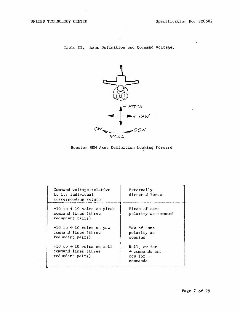
3.1.1.1.2.2 SRM Axes Definition. Table II shows the SRM axes definitionand indicates the command voltages and polarities required to provide controlmoments about the roll, pitch, and yaw axes.
Page 6 of 27

Externally Directed Force
UNITED TECHNOLOGY CENTER Specification No. SC0501
Table II. Axes Definition and Command Voltage
___ ++Pitch
T+YaWCW~~CCW
RoIT -
Booster SRM Axes Definition Looking Forward
r--------------,------------...--.--I, Command Voltage Relative
to its individual correspondingreturn
-10 to +10 volts on pitchcommand lines (three redundantpairs)
-10 to +10 volts on yawcommand lines (three redundantpairs)
-10 to +10 volts on rollcommand lines (three redundantpairs)
Pitch of same polarity ascommand
Yaw of same polarity ascommand
Roll CW for (+) commands andCCW for (-) commands
I!
I
I!i
I3.1.1.1.2.3 SRM Thrust Vectoring. The nominal SRM pitch (yaw) thrust
vector angle, as a function of command voltage and nominal motor chamber pressure,shall be as shown in Figure 20 and as described in the TVC Math. Model, for allSRM thrust vector angles between ±10 degrees.
3.1.1.1.2.4 SRM Thrust Vector Moment Arm. The nominal SRM pitch (yaw)thrust vector moment arm as a function of command voltage and nominal motorchamber pressure shall be as shown in Figure 21 and as described in the TVCMath. Model, for all thrust vector moment arms within + (TBS)inches.
Page 7 of 27

UNITED TECHNOLOGY CENTER Specification No. SC0501
3.1.1.1.2.5 TVC Hysteresis. Three-sigma deviations from nominal TVCrelationships in 3.1.1.1.2.3 and 3.1.1.1.2.4, due to command voltage reversals,shall not exceed the greater of ±(TBS)% or ±(TBS) degrees, or the great~r of±(TBS)% or ± (TBS) inches, respectively, from ignition to web action time; andshall not exceed the greater of ±(TBS)% or ±(TBS) degrees, or ±(TBS)% or±(TBS) inches, respectively, from web action time to action time.
3.1.1.1.2.6 TVC Variability. Three-sigma variability of the SRM thrustvector angle shall not exceed the greater of ±(TBS)% or ±(TBS) degrees, and variability or the slope of the command voltage-to-thrust vector moment arm relationship shall not exceed the greater of ±(TBS)% or ±(TBS) inches/volt from ignitionto web action time; and shall not exceed the greater of ±(TBS)% or ±(TBS) degrees,and the greater of ±(TBS)% or ±(TBS) inches/volt, respectively, from web actiontime to action time. This variability shall include all deviations, tolerances,and cross-coupling efforts excepting variations in the nominal motor chamberpressure with SRM mean bulk temperature.
3.1.1.1.2.7 Roll Control Moments. The nominal stage roll control momentas a function of roll command voltage and nominal motor chamber pressure shall" beas shown in Figure 22 and as described in the TVC Math. Model. Three-sigmavariations shall not exceed the greater of ±(TBS)% or ±(TBS) inch-pounds fromweb action time to action time. Three-sigma deviations from the nominal commandvoltage-to-roll control moment relationship, due to command voltage reversal,shall not exceed ±(TBS) inch-pounds from ignition to web action time, and ±(TBS)inch-pounds from web action tline to action time.
3.1.1.1.2.8 Resolution. The TVC system resolution within the range of±10 degrees of SRM thrust vector angle shall not exceed (TBS) volts fromignition to web action time and (TBS) volts from web action time to action time.
3.1.1.1.2.9 Frequency Response. The total thrust vector control systemfrequency response at any ambient voltage command level in the defined nozzleaxes for motor chamber pressures between (TBS) and (TBS) psia shall be as specifiedby the upper and lower limits of the amplitude ratio and phase lag given inFigure 23. This curve is valid as long as the maximum command voltage does notexceed TBS VDC, the velocity or rate of change of the command voltage is belowthe minimum slew rates specified in Figure 24 and the minimum cummand isgreater than (TBS) VDC.
3.1.1.1.2.10 Slew Rate. The TVC system shall be capable of changing thevehicle thrust vector angle at a minimum slew rate of 5 degrees per secondthroughout motor operating time. This requirement shall apply for all motor andactuation system operating conditions in conjunction with external nozzle loadsand environments as specified in (TBS). Slew rate is defined as the instantaneousrate of change of thrust vector angle for command changes exceeding (TBS) voltsat a rate exceeding (TBS) volts per second. The minimum and maximum slew ratelimits as a function of flight time shall be as shown in Figure 24. Minimumslew rate is derived assuming nominal SRM performance combined with minus3-sigma control system performance and plus 3-sigma external nozzle loads.Maximum slew rate is derived assuming nominal SRM performance combined withplus 3-sigma control system performance and minus 3-sigma nozzle loads.
Page 8 of 27

UNITED TECHNOLOGY CENTER Specification No. SC0501
3.1.1.1.3 SRM Ignition. Each SRM of the booster stage shall provide anintegral igniter motor that shall perform the function of initiating SRM ignition.Simultaneous ignition initiation of each SRM of the booster stage shall beaccomplished by receipt of simultaneous command signals from the orbitet or fromground equipment to the ordnance electrical system of each SRM.
3.1.1.1.4 Staging Performance. (TBS) staging motors per S~~, (TBS) inthe nose section, and (TBS) in the aft section shall supply the lateral stagingimpulse to each SRM to fulfill the requirements of the shuttle booster generalsystems specification (TBS). Staging ignition initiation shall be accomplishedby the SRM ordnance electrical system upon receipt of command from the orbiter.
3.1.1.1.5 Flight Safety. To preclude or limit hazard to personnel and/orequipment, each SRM of the booster stage shall incorporate: (1) a thrusttermination system with provisions for activation when commanded by the orbitervehicle or upon detection of an inadvertent separation of an SRM from the launchvehicle, and (2) an inadvertent separation detection system (ISDS), and (3) anemergency detection system for monitoring critical booster parameters and providing signals to the orbiter crew. The design of these systems shall be in accordance with the requirements of Range Safety (TBS) Shuttle Booster General SystemSpecification (TBS) and Component CEI Specifications.
3.1.1.1.5.1 Thrust Termination Performance. A two-port thrust terminationsystem shall be provided on each solid rocket motor. The thrust terminationsystem shall effectively neutralize the axial thrust of each SRM by ventingthe combustion chamber at the forward end of each SRM. Each solid rocket motorand its thrust termination system shall be capable of surviving the environmentscreated by thrust termination for a period of (TBS) seconds after the initiationof thrust termination. The thrust termination performance for a single solidrocket motor is shown in Figure 25.
3.1.1.1.5.2 Emergency Detection System. The emergency detection systemshall provide the following output signals to the orbiter:
(a) Fast Failure: A signal shall be present when an emergencycondition exists which will result in motor failure within (TBS)seconds and an immediate abort is required;
(b) Slow Failure: A signal shall be present when an emergencycondition exists which will result in motor failure after atleast (TBS) seconds from initial detection;
(c) Unverfied Failure: A signal shall be present when an emergencycondition is sensed by only one of a pair of redundant transducers;
(d) Emergency Detection System Self Check: A signal shall bepresent when all malfunction detection system self-check circuitsare indicating proper operation.
An emergency detection system input shall be provided such that the system canbe disabled on command from the orbiter.
Page 9 of 27

UNITED TECHNOLOGY CENTER Specification No. SC0501
3.1.1.1.5.3 Inadvertent Separation Detection System (ISDS). Each SRM ofthe booster stage shall provide an ISDS that shall detect the inadvertent lossof electrical cabling between the orbiter/launch vehicle and automaticallyinitiate thrust termination prior to receipt of a disable command from theorbiter. The ISDS shall be an integral part of the SRM ordnance electricalsystem.
3.1.1.1.6 Electrical Power, Control, and Distribution. Each SRM of thebooster stage shall provide the airborne power, switching capability from groundpower to airborne power, and the distribution of all airborne power to the TVCsystem, ordnance system, emergency detection system, and flight instrumentationsystem. Each SRM of the booster stage shall receive and distribute groundpower for SRM systems ground operation and checkout. All systems shall operatefrom 28 VDC (nominal) power sources.
3.1.1.2 Secondary Performance Characteristics.
3.1.1.2.1 Instrumentation System Performance Characteristics. The boosterstage instrumentation system shall provide signal outputs to the orbiter for thepurpose of verification and evaluation of booster stage status and performanceprior to and during flight. The functional status of specified redundancyfeatures included in the other booster stage systems shall be indicated bydiscrete output signals to the orbiter.
3.1.1.2.2 Checkout Provisions. Provisions shall be made to allow thefollowing booster stage verification tests to be performed on an assembledlaunch vehicle via the airborne and ground electrical interfaces.
(a) Detailed functional tests, as specified in (TBS) , of all electricaland mechanical subsystems, including operational status of redundantfeatures.
(b) 'System operability (quick-look) tests, as specified in (TBS) of theflight critical active systems, providing go/no go signals, includingchecks of redundant features.
(c) Integrated-system test, as specified in (TBS) , performed as asimulated countdown and flight with the complete launch system.
(d) Booster stage component malfunction isolation and component checkouttests as specified in (TBS).
During these tests, airborne items which are not operated due to safety, oneoperation capability, reduced hold capability, or physical difficulty will bechecked in a non-operating mode to verify operable status and proper installation. No nonflight hardware will be connected to the stage for these testsexcept the normal ground umbilical cable.
3.1.1.2.3 Mass Property Requirements. Nominal values of mass, center ofgravity (cg) location, and moments of inertia shall be determined as a functionof flight characteristics. Three sigma tolerances on the prelaunch values shallbe as follows:
Page 10 of 27

UNITED TECHNOLOGY CENTER
cg location - longitudinalpitch planeyaw plane
Mass
Moments of inertia
Specification No. SCOSOI
Individual SRMs Stage
+7.7 inches +}±1.6 inches +
±1.7 inches +fTBS
±3,600 pounds +
±lO percent +
The mass fraction of the motor shall be TBS minimum using the "inert"motor definition in Section 6.
3.1.1.2.4 Hold and Reaction Time Requirements. The booster stage shallbe capable of maintaining a launch hold at T-(TBS) minutes for 30 days withoutenvironmental protection (shall allow electrical maintenance of batteries viathe ground umbilical cable during the hold). The booster stage shall be capableof a launch reaction time of(TBS)hours after integrated system test and a systemabort recycle time for causes external to the vehicle of TBS hours. The boosterstage shall be capable of proceeding to T-(TBS) seconds returning to T-(TBS)minutes and holding for 30 days.
3.1.2 Operability. The SRM shall conform to the following operabilityrequirements.
3.1.2.1 Reliability. The reliability of the SRM booster stage shall beas specified in the shuttle booster general systems specification (TBS).
3.1.2.2 Maintainability. The SRM booster stage shall meet the maintainability requirements of MIL-STD-470. Quantitative requirements shall be established for the contributions to system downtime considering the AGE, facilities,and airborne portions of the vehicle system. The maintainability apportionment shall be consistent with the probability of launch-on-time requirements.Downtime shall be interpreted as active downtime defined in MIL-STD-778 andshall not be greater than (TBS) hours mean active time to restore. Mean maintenance-downtime (M) is described for corrective-maintenance functions as:
M hours
Nc
Where:
Nc
Mct
=
=
=
mean maintenance correction-time for sub-system(arithmetic mean)
number of corrective maintenance-functions formodular remove/replace maintenance concept
active maintenance correction-time per correctivemaintenance task
Page 11 of 27
UNITED TECHNOLOGY CENTER
The quantitative M allocations shall be as follows:
(TBS)
Specification No. SC0501
The M allocations do not apply on a lower level of assembly because maintenanceor test results pertinent to a requirement for maintenance only occurs at thefully assembled level. The above subsystems are defined in the UTC SystemEffectiveness Plan, (TBS).
3.1.2.2.1 Maintenance and Repair Cycles. Maintainability analyses shallestablish time goals for the completion of maintenance activities and theassociated design and procedural approaches. This data will be incorporatedinto equipment specifications and, thus, constitute objectives to be accomplishedduring the design process. Maintenance functions for support of the SRM arecorrective-maintenance functions. Preventive maintenance is not considered inthe maintenance concept.
3.1.2.2.2 Service and Access. Access shall be provided so all interfaceconnections and maintenance operations can be performed. The ordnance and TVCsubsystems shall be capable of checkout and servicing while installed in the SRM.Access requirements shall be evaluated to ascertain performance of correctivemaintenance tasks upon which active maintenance downtime is based, and whichare organizational level remove/replace maintenance functions.
3.1.2.3 Useful Life. The SRM booster stage shall comply with shuttlebooster general system specifications (TBS). The SRM booster stage shall meetthe requirements of this specification after exposure to the environmentspecified in paragraph 3.1.2.4 for a period of one year. Cyclic life limitations shall be as defined in the component CEl specifications (see paragraph3.3.1.3)
3.1.2.4 Environmental.
3.1.2.4.1 Prelaunch. The SRM booster stage shall perform as specifiedherein after exposure to the following environments:
(a)
(b)
Temperature - Surrounding air temperatures between 250 and 1000 Fwith mean bulk propellant temperatures of 400 to 900 F for periodsup to 60 days
Humidity - Relative humidities of up to 100 percent includingcondensation in the form of water or frost for periods up to 60 days.
Page 12 of 27

UNITED TECHNOLOGY CENTER Specification No. SC0501
(c) Fungus - Exposure to fungi equivalent to 28 days of exposure toselected fungi as described in Specification MIL-E-5272. As adesign goa1,materia1s which are fungus nutrient· shall not be used.
(d) Sand and dust - Exposure to windblown graded sand and dust equivalentto exposure for 6 hours in a sand-and-dust chamber as described inSpecification MIL-E-5272
(e) Sunshine - Normally exposed, nonmetallic materials shall withstandthe deteriorating effects of direct sunlight for periods up to 60 days.
(f) Salt fog - Exposure to salt fog equivalent to exposure to a 20-percentsalt spray for:
(i) 10 hours for internally-mounted equipment
(ii) 50 hours for externally-mounted equipment
(g) Rain - Exposure to rain equivalent to 4 inches per hour for 2 hours
(h) Wind and gusts - Exposure to the wind and gusts prevalent at the launchbase as defined in (IRS)
(i) Propellant compatibility - (TBS)
(j) Loads - Exposure to loads induced by the winds and gusts specified in(h) above
(k) Overpressure - Exposure to overpressures induced by an incident on antdjacent launch pad as defined in (TBS)
3.1.2.4.2 Launch and Flight. The SRM booster stage shall perform asspecified herein during and after exposure to the environments specified in theshuttle booster general system specification (TBS)
3.1.2.4.3 Storage. The SRM shall perform as specified herein when itso 0
components CElls are stored at mean bulk temperatures between 40 F and 90 F withpropellant surfaces protected from humidity in excess of 50 percent RH.
3.1.2.5 Transportability. The assembled SRM will not be transported.Transportation environments will be within the limits specified in paragraph3.1.2.4. The forward section, segments, and aft section shall be transportablein the clevis-down or horizontal position without degradation of the propellantor bonding to the extent that would preclude the SRM from performing as specifiedherein. Component CElls shall be designed so that ally passive means of environmental protection are required during transportation.
3.1 a 2.6 Human Performance. The SRM booster stage and associated groundequipment shall meet the human-performance requirements of (TBS).
Page 13 of 27
UNITED TECHNOLOGY CENTER
3.1.2.7 Safety.
Specification No. SC0501
3.1.2.7.1 Flight Safety - Design of airborne systems shall meet therequirements of applicable range safety specifications (TBS).
3.1.2.7.2 Ground Safety. The SRM shall be compatible with the shuttlebooster general specification (TBS).
3.1.2.7.3 Nuclear Safety. Not applicable.
3.1.2.7.4 Personnel Safety. Provisions for personnel safety shall bein accordance with the shuttle booster general specification (TBS).
3.1.2.7.5 Explosive and/or Ordnance Safety. The system shall comply withthe requirements of paragraph 3.1.2.7.4 of this CEI Specification and the shuttlebooster general specification (TBS) to the extent specified in the componentCEI Specif~cations. The explosive classification of each assembled SRM shallbe Class 2in accordance with AFM-127-l00.
3.2 Configuration Item Definition.
3.2.1 Interface Requirements.
3.2.1.1 Schematic Arrangement. Each SRM shall conform to the dimensionsshown in UTC Drawing C09007. The schematic arrangement of the overall systemand each electrical system shall be as shown in Figures 26 through 30 and UTCDrawing (TBS).
Page 14 of 27

UNITED TECHNOLOGY CENTER
3.2.1.2 Detailed Interface Definition.
Specification No. SC0501
3.2.1.2.1 System Interfaces. All interfaces between the SRM boosterstage, the orbiter vehicle, and the facility will be defined and controlledby the following interface documents:
(TBS)
3.2.1.2.2 AGE Interfaces. Necessary interfaces for the SRM booster stagelaunch pad testing shall be provided for mating with the following equipment: .
(TBS)
3.2.2 Component Definition.
3.2 0 2.1 Customer-Furnished Property List. The following items, which areto be furnished by the customer, are required for flight CEI operation:
(a) Component CEI's (see paragraph 3.3.1.3)
3.2.2.2 Engineering-Critica1-Components List. Engineering criticalcomponents are listed in the component CEI specifications.
,3.2.2.3 Logistics Critical Components List. Logistics critical components
are listed in the component CEI specifications.
3 0 3 Design and Construction.
3.3.1 General Design Features.
3 0 3.1.1 General De~ign and Construction Requirements. The SRM designshall comply with the shuttle booster general system specification (TBS).
3.3.1.2 Description o
3 0 3.1.2.1 Solid Rocket Booster Stage. The solid rocket booster stage shallconsist of two solid rocket motors, their attach structure, and the varioussystems required by this specification. Each motor shall be a three-segment156-inch diameter motor with spherical end closures at each end. The seg~ents
and closures are joined with a pressure sealing clevis joint. An aerodynamicnose fairing attaches to the forward end and houses portions of the electricalsystem and the forward staging rocket motors.
Page 15 of 27

UNITED TECHNOLOGY CENTER Specification No. SC0501
3.3.1.2.2 Segments and Closures. Each segment is insulated with rubberand cast with composite, aluminized propellant in the form of a ho11ow·cy1inder.One end of the grain is restricted from burning by a rubber restrictor and atapering of the central perforation provides the required tai10ff thrust characteristics. The forward closure is insulated with rubber and propellant is castin the form of an eight-point star with ports provided to allow for thrusttermination. The aft closure is rubber insulated and has a circular port grainconfiguration.
3.3.1.2.3 Nozzle and Exit Cone. To the aft closure is attached a 52-inchdiameter ablative throat and a 200 conical ablative exit cone with an expansionratio of 10·6:1.
3.3.1.2.4 Thrust Vector Control System. Thrust vector control is providedby movable nozzles on each SRM. Each nozzle is supported by a constant volumefluid filled bearing which transmits the nozzle b1owoff loads and thrust vectoring loads to the SRM by means of two annular rolling convolutes. Movement ofthe nozzle, within the limits of the fluid bearing, is produced by actuatorsplaced in mutually perpendicular planes. Hydraulic power for the actuators isprovided by a regulated pressure supply system using a solid propellant gasgeneration as the energy source. Actuator position control is accomplishedby an electronic control unit which resolves and conditions vehicle guidancesystem steering commands into the appropriate control responses.
3.3.1.2.5 Attach Structure. The two solid rocket motors are attached tothe orbiter tank by a thrust transmission structure near the forward end of eachSRM which transmits SRM thrust to the orbiter, and by an aft structure whichreacts the transverse and radial loads. The aft structure also provides groundsupport for a single SRM during buildup and ground support for the assembledvehicle. Provisions for mounting staging motors are provided at the fore andaft ends of each SRM.
3.3.1.2.6 Emergency Detection System. Detection of impending solidrocket motor failures necessitating a mission abort is provided by this system.The output of various pairs of redundant transducers are compared to predeterminedcriteria to determine presence of an impending failure situation. Parallelredundancy is utilized in this system to reduce the possibility of an inadvertentmission abort.
3.3.1.2.7 Instrumentation System. The instrumentation system shall monitorpertinent booster stage parameters and supply conditioned signals to the orbitertelemetry system to verify and evaluate booster stage status and performanceprior to and during flight. The system also provides signal inputs and outputsvia the ground umbilical cable required to accomplish verification tests on thebooster stage. The design of the instrumentation system shall be such that nosingle instrumentation system component failure will result in performancedegradation of any other booster stage system such that the limits of thisspecification are exceeded.
Page 16 of 27

UNITED TECHNOLOGY CENTER Specification No. SC0501
3.3.1.2.8 Ordnance System. The ordnance systems for the SRM booster stageprovides the capability of performing the functions of booster ignition~ staging,thrust termination, and inadvertent separation detection by initiation of ordnancedevices. The ordnance electrical system provides the power and control of thefiring units to initiate the devices. Firing unit charging is a'.:,~c.rr.p1ished uponcommand from tlie orbiter vehicle oJ:" ~round __ ~tation.
3.3.1.2.9 Redundancy. Redundancy shall be utilized, to the maximum extentpracticable, in all systems to exclude the possibility of a single non-structuralfailure causing out-of-specification performance.
3.3.1.2.10 Weights. The predicted component weights are given in Table III.
Table III.
Component
Attach structureForwardAft
Separation system
'Solid motor (empty)Case
Forward ClosureSegments (Total)Aft ClosureAssembly Hardware
InsulationForward ClosureSegments (Total)Aft Closure
IgnitorThrust TerminationNozzle
MovableFixed
Actuation System
Component Weights
Weight
(20,450)7,850
12,600
1,238
(135,857)( 99,799)
18,51873,1377,744
400(15,963)
3,3649,2463,353
3782,043
(17,674)13,6314,043
1,080
Electrical and Instrumentation
Weight Empty
Solid Propellant
Single Loaded Motor - Total
STAGE TOTAL
1,403
160,028
1,250,000
1,410,028
2,820,556
Page 17 of 27

UNITED TECHNOLOGY 'CENTER Specification No. SC0501
3.3.1.3 Component Configuration Items. The following subparagraphs identifythe component configuration items which form each SRM of the booster stage.
3.3.1.3.1 Forward Section, Rocket Motor. Each rocket motor forward sectionshall be in accordance with UTC Specification (TBS).
3.3.1.3.2 Aft Section, Rocket Motor. The rocket motor aft section shallbe in accordance with UTC Specification (TBS).
3.3.1.3.3 Segment Assembly, Rocket Motor. The rocket motor segmentassembly shall be in accordance with UTC Specification (TBS).
3.3.1.3.4 Nose Section, Rocket Motor. The rocket motor nose section shallbe in accordance with UTC Specification (TBS).
3.3.1.3.5 Extension, Nozzle Exit Cone. The nozzle exit cone extensionshall be in ac~ordance with UTC Specification (TBS).
3.3.1.3.6 Battery Set. All flight batteries shall be in accordance withUTC Specification (TBS).
3.3.1.3.7 Ordnance Set, Rocket Motor. The rocket motor ordnance set shallbe in accordance with UTC Specification (TBS).
3.3.1.3.8 Mechanical Hardware Set, Rocket Motor. The rocket motor mechanicalhardware set shall be in accordance with UTC Spectfication (TBS).
3.3.1.3.9 Aft Structure, Rocket Motor. The rocket motor aft structureshall be in accordance with UTC Specification (TBS).
3.3.1.3.10 Flight Instrumentation Set, Rocket Motor. The rocket motorflight instrumentation set shall be in accordance ~ith UTC Specification (TBS).
3.3.2 Selection of Specifications and Standards. The selection of specifications and standards shall be in accordance with shuttle booster generalspecification (TBS).
3.3.3 Materials, Parts, and Processes. Materials, parts and processesused in each SRM shall conform to the applicable requirement as specified inshuttle booster general specification (TBS) as further defined by componentCEI Specifications referenced in paragraph 3.3.1.
3.3.4 Standard and Commercial Parts. Standard and commercial parts shallbe in accordance with shuttle booster general system specification (TBS).
3.3.5 Moisture and Fungus Resistance. Materials used in this CEI shallcomply with the requirements of shuttle booster general system specification(TBS) as specified in the component CEI Specifications.
Page 18 of 27

PNITEDTECHNOLOGY CENTER Specification No. SC0501
3.3.6 corrosion of Metal Parts. All metal parts used in fabrication ofthe SRM shall be corrosion resistant or suitably treated to resist corrosionwhen exposed to the environmental conditions specified in paragraph 3.1.2.4.Wherever practical, the use of dissimilar metals, as defined in StandardMS33586, in contact with each other shall be avoided.
3.3.7 Interchangeability and Replaceability. The interchangeability andreplaceability, as specified in MIL-STD-447, of the SRM components shall bein accordance with MIL-I-8500.
3.3.8 Workmanship. Eam SRM shall be fabricated and finished in such amanner that criteria of appearance, fit, and adherence to specified tolerancesshall be observed. Particular attention shall be given to the neatness andthoroughness of soldering, wiring, marking of parts and assemblies, plating,painting, riveting, machine-screw assemblage, welding and brazing, and freedomof parts from burrs and sharp edges.
3.3.9 Electromagnetic Interference. ~h SRM shall meet the electromagnetic interference requirements of Electromagnetic Compatibility ControlPlan (TBS).
3.3.10 Identification and Marking. Eam SRM shall be identified and markedin accordance with MIL-STD-130 and (TBS). -.
3.3.11 Storage. E~h assembled SRM and its components shall conform to thestorage requirements of paragraphs 3.1.2.3 and 3.1.2.4, as applicable.
3.3.12 Cleanliness. ~h SRM and its components shall meet the cleanlinessrequirements of (TBS).
4. QUALITY ASSURANCE PROVISIONS.
4.1 Category I Test. Category I tests as used herein shall be definedas contractor-performed component, subsystem and full-scale static sea level tests.Records and documentation of results of all Category I testing.shali be maintained in comprehensive, legible format.
4.1.1 Engineering Test and Evaluation. Engineering tests and evaluationsshall be conducted to provide maximum assurance of successful completion of thequalification and category II system tests specified below.
Page 19 of 27

UNITED TECHNOLOGY CENTER Specification No. SC0501
4.1.1.1 Development Testing. (TBS) motor firing tests shall be conducted at a UTC test facility during the development phase, (TBS) verticalat UTC and (TBS) horizontal thrust termination test. Motors shall be instrumented during these firings to evaluate the internal ballistic performance,TVC performance, and electrical system performance. Test configuration shallbe as specified in (TBS).
4.1.2 Preliminary Qualification Tests. (TBS) rocket motors identicalin configuration to the final flight configuration will be fired in a preliminary flight rating test (PFRT) program to be conducted at a UTC testfacility. The differences in configuration will be limited to those requiredfor the inverted-from-flight attitude firings and are defined in (TBS).Successful completion of these firings will constitute the preliminary qualification test program.
4.1.3 Formal Qualification Tests. The following subparagraphs specifythe requirements for, and methods of, formally verifying that each requirement in Section 3 has been satisfied.
4.1. 3.1 . Inspection. The following requirements of Section 3 shall beverified by an inspection at a time and place to be determined mutually bythe customer and UTC: (TBS)
4.1.3.2 Analysis. Conformance to the following requirements shall beverified by comparative analysis of engineering documentation developed underprevious programs and during the testing of 4.1.1.1 and 4.1.2. No furthertesting will be conducted to verify conformance to these requirements. (TBS)
4.1.3.3 Demonstrations. Not applicable.
4.1.3.4 Tests. The following requirements in Section 3 shall be verifiedduring the preliminary qualification tests of 4.1.2: (TBS)
4.1.4 Reliability Tests and Analysis. At the start of the acquisitionphase a reliability mathematical model shall be presented to justify reliabilityfailure allocations for the various CEI components. The results of tests,failure reports, a·nd conclusions as to system reliability shall be presented tothe customer throughout the acquisition program. No special testing shall bespecifically conducted to satisfy the provisions of 3.1.2.1.
4.1.5 Engineering Critical Component Qualification. Not applicable.
4.1.6. Interface Testing.
4.1.6.1 System Interfaces. Conformance to the requirement of paragraph3.2.1.2.1 "System Interface" shall be verified by comparative analysis ofengineering documentation developed under previous programs and during selectedtesting according to 4.1.1.1 and 4.1.2 as follows:
Page 20 of 27

UNITED TECHNOLOGY CENTER Specification No. SC0501
4.1.6.1.1 Parametric Interfaces. SRM seal-level ballistic and TVC performance as specified in (TBS) shall be verified to the extent analyzed by 4.1.3.2and 4.1.3.4.
4.1.6.1.2 Structural and Dynamic Load Interfaces. These interfaces asspecified in (TBS) , shall be verified only to the extent that mass propertyrequirements shall be verified as appropriate according to 4.1.3.2.
4~1.6.l.3 Electrical Interfaces. These interfaces as specified in (TBS)shall be tested as defined by (TBS). (ref: 4.1.6.1.4)
4.1.6.1.4 Testing Interfaces. These interfaces, as specified in (TBS)shall be verified to the extent where UTC electrical test requirements areapplicable to the testing of 4.1.1.1 and 4.1.2. (reference 4.1.6.1.8 forfluid systems verifications.)
4.1.6.1.5 Physical Interfaces. Dimensional requirements only, as specifiedin (TBS), shall be verified according to the inspections of 4.1.3.1.
4.1.6.1.6 Electrical Interfaces. These interfaces, as specified in (TBS),shall be verified by testing as defined by (TBS). (ref.: 4.1.6.1.4)
4.1.6.1.7 Envelope Interface~ Dimensional requirements only, as specifiedin (TBS), shall be verified according to the inspections of 4.1.3.1.
4.1.6.1.8 Fluid Interfaces. To the extent that the fluid interfaces arerequired for the testing of 4.1.1.1 and 4.1.2, the interfaces (mechanical,fluid quantity and fluid quality) used for static test will be consistent withthe requirements of (TBS) and thereby verify adequacy of requirements.
4.1.6.1.9 Installation Interfaces. Dimensiona1.requirements only, asspecified in (TBS), shall be verified according to the inspections of 4.1.3.1.
4.2 Category II Test Program. The requirements of 3.3.9 shall be verifiedby tests to be performed after the SRM stage has been integrated into an assembledlaunch vehicle. The solid rocket motors shall demonstrate the following minimumvehicle centerline vacuum web action time total impulse when assembled andlaunched as a Stage of the space shuttle launch vehicle in accordance withMIL-STD-471: (TBS)
5. PREPARATION FOR DELIVERY. (TBS)
6. NOTES.
6.1 Supplemental Information. Maximum use shall be made of componentsqualified under other programs.
6.1.1 Definitions. For purposes of this specification the followingdefinitions shall apply:
Page 21 of 27
UNITED TECHNOLOGY CENTER Specification No. SC0501
6.1.1.1 Web Action Time. Web action time shall be defined as fo~lows:
The start of web action time shall be that point in the pressure/time traceat which the head end pressure has reached 75 percent of maximum. The end ofweb action time shall be defined by the following geometric cons~ruction.
Extend the general shape of the pressure time curve prior to and immediatelyafter the beginning of tail-off. Then bisect the angle formed by this extension.Extend this bisector to intersect the pressure/time trace. The time that corresponds to this intersection point is the end of web action time.
6.1.1.2 Action Time. Action time is defined as beginning when the pressure has risen to 75 percent of the maximum chamber pressure and ending whenthe head end pressure has fallen to 10 percent of the maximum chamber pressure.
6.1.1.3 Delivered Specific Impulse. The delivered specific impulse shallbe defined as the total impulse along the nozzle centerline delivered duringweb action time divided by the weight of propellant expended during web actiontime. Delivered specific impulse at plant site shall be extrapolated to specificimpulse at vacuum conditions. The methods used to determine the weight of expended propellant and to extrapolate the data shall be presented subject tocustomer approval.
6.1.1.4 Regressivity. Regressivity is defined as the maximum vacuumthrust minus the vacuum thrust at end of web action time divided by the maximumvacuum thrust. All thrusts are taken along the nozzle centerline.
6.l.l~5 Action Time Total Impulse. Action time total impulse is definedas the integrated thrust along the nozzle centerline over the action time.
6.1.1.6 Initial Vacuum Thrust. Initial vacuum thrust is defined as thatvacuum thrust along with the nozzle centerline at the completion of ignition.Initial vacuum thrust may be calculated from sea level data by adding 183,603 lb
fto the measured sea level nozzle centerline thrust.
6.1.1.7 Web Action Time Total Impulse. Web action time total impulse isdefined as the integrated thrust along the nozzle centerline over the web actiontime.
6.1.1.8 Ignition Delav. Ignition delay is defined as the time intervalbetween fire signal and when the motor chamber pressure reaches 75 percent ofthe initial peak pressure.
6.1.1.9 Tailoff. Tailoff is defined as the time interval between webaction time and action time.
6.1.1.10 Total Prelaunch Weight (Nominal). Total prelaunch weight isdefined as the sum of all motor weights which includes propellants and inerts.
6.1.1.11 Expendable Weight. Expendable weight is defined as the weightof those items that are expended from the motor which include propellant, insulation and liner, nozzle, igniter charge, and weather seal.
Page 22 of 27
UNITED TECHNOLOGY CENTER Specification No. SC0501
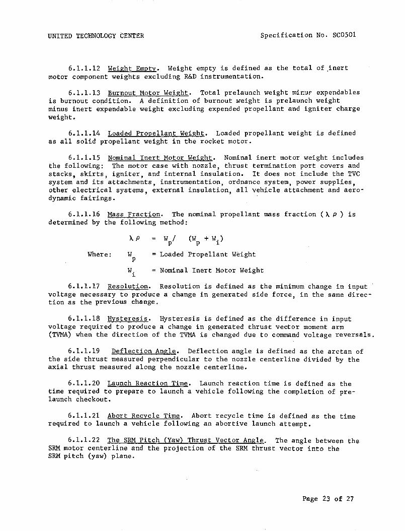
6.1.1.12 Weight Empty. Weight empty is defined as the total of ,inertmotor component weights excluding R&D instrumentation.
6.1.1.13 Burnoutis burnout co~dition.
minus inert expendableweight.
Motor Weight. Total prelaunch weight mir.uF expendablesA definition of burnout weight is prelaunch weightweight excluding expended propellant and igniter charge
6.1.1.14 Loaded Propellant Weight. Loaded propellant weight is definedas all solid propellant weight in the rocket motor.
6.1.1.15 Nominal Inert Motor Weight. Nominal inert motor weight includesthe following: The motor case with nozzle, thrust termination port covers andstacks, skirts, igniter, and internal insulation. It does not include the TVCsystem and its attachments, instrumentation, ordnance system, power supplies,other electrical systems, external insulation, all vehicle attachment and aerodynamic fairings.
6.1.1.16 Mass Fraction. The nominal propellant mass fraction (~p) isdetermined by the following method:
~p W / (W + W.)P P ~
Where: W = Loaded Propellant Weightp
W. Nominal Inert Motor Weight~
6.1.1.17 Resolution. Resolution is defined as the m~n~mum change in inputvoltage necessary to produce a change in generated side force, in the same direction as the previous change.
6.1.1.18 Hysteresis. Hysteresis is defined as the difference in inputvoltage required to produce a change in generated thrust vector moment arm(TVMA) when the direction of the TVMA is changed due to command voltage reversals.
6.1.1.19 Deflection Angle. Deflection angle is defined as the arctan ofthe side thrust measured perpendicular to the nozzle centerline divided by theaxial thrust measured along the nozzle centerline.
6.1.1.20 Launch Reaction Time. Launch reaction time is defined as thetime required to prepare to launch a vehicle following the completion of prelaunch checkout.
6.1.1.21 Abort Recycle Time. Abort recycle time is defined as the timerequired to launch a vehicle following an abortive launch attempt.
6.1.1.22 The SRM Pitch (Yaw) Thrust Vector Angle. The angle between theSRM motor centerline and the projection of the SRM thrust vector into theSRM pitch (yaw) plane.
Page 23 of 27

UNITED TECHNOLOGY CENTER Specification No. SC0501
6.1.1.23 SRM Pitch (Yaw) Plane. The plane defined by the SRM motorcenterline and a line which is normal to the SRM centerline and parallel tothe vehicle pitch (yaw) plane.
6.1.1.24 The SRM Pitch (Yaw) Thrust Vector Moment Arm. The length ofthe perpendicular line from the SRMmotor centerline at miss1e station (TBS)to the SRM projection of the thrust vector into the pitch (yaw) plane.
6.1.1.25 Solid Rocket Motor Centerline. The line joining the centerof the aft c1osure-to-nozz1e throat bolt circle to the center of the forwardclosure in the plane of the forward attach structure.
6.1.1.26 Nozzle Centerline. The line joining the center of the nozzlethroat to the center of the nozzle exit.
6.1.1.27 Stage Centerline. The line Jo~n~ng the center of the stage/orbiter assembly joint bolt circle and the center of- the aft structure supportstructure.
6.1.1.28 SRM Thrust Vector. The force vector whose magnitude and variability is defined by paragraph 3.1.1.1.1, and whose direction and variabilityis defined by paragraph 3.1.1.1.2.
6.1.1.29 Stage Roll Plane. A plane perpendicular to the stage centerlinewhich intersects the stage centerline at missile station (TBS).
6.1.1.30 Stage Roll Control Moment. The resultant moment about the stagecenterline of the sum of the SRM thrust vectors projected into the stage rollplane.
Page 24 of 27

UNITED TECHNOLOGY CENTER
10. APPENDIX
Specification No. SC0501
10.1 . Test Configuration. The static test configuration of the SRM shallconform to UTC drawing (TBS). This drawing shows several obvious differencesfrom the flight configuration. These differences shall not affect performancebut are related to ordance, structural, and instrumentation measurements whichpertain directly to the static test program.
Specific differences shall include the following areas: (TBS)
'Page 25 of 27

UNITED TECHNOLOGY CENTER Specification No. SC0501
The following figures are to be supplied:
Figure 1- Ignition Transient 156-Inch Thrust Versus Time & NozzleSea Level at 60°F
Figure 2. Ignition Transient 156-Inch Pressure Versus Time at 60°F
Figure 3. Vacuum Thrust Versus Time, 40°F
Figure 4. Vacuum Thrust Versus Time, 60°F
Figure 5. Vacuum Thrust Versus Time, 70°F
Figure 6. Vacuum Thrust Versus Time, 90°F
Figure 7. Sea Level Thrust Versus Time, 40°F
Figure 8. Sea Level Thrust Versus Time, 60°F
Figure 9. Sea Level Thrust Versus Time, 70°F
Figure 10. Sea Level Thrust Versus Time, 90°F
Figure 11. Forward Head Pressure Versus Time, 40°F
Figure 12. Forward Head Pressure Versus Time, 60°F
Figure 13. Forward Head Pressure Versus Time, 70°F
Figure 14. Forward Head Pressure Versus Time, 90°F
Figure 15. Aft End Pressure Versus Time, 40°F
Figure 16. Aft End Pressure Versus Time, 60°F
Figure 17. Aft End Pressure Versus Time, 70°F
Figure 18. Aft End Pressure Versus Time, 90°F
Figure 19. Aft to Forward Head Pressure Ratio Versus Time
Figure 20. Thrust Vector Angle Versus Command Voltage andChamber Pressure
Figure 21. Thrust Vector Moment Arm Versus Command Voltageam Nominal Chamber Pressure
Figure 22. Roll Control Moment Versus Roll Command Voltageand Nominal Chamber Pressure
Page 26 of 27

UNITED TECHNOLOGY CENTER Specification No. SC0501
Figure 23. Frequency Response
Figure 24. Slew Rates
Figure 25. Net Thrust Versus Time from Thrust Termination Actuation
Figures 26 through 30. Schematic Arrangements of SRM Electrical Systems
Page 27 of 27
UNITED TECHNOLOGY CENTER
(PRELIMINARY)
Specification No. SC0502
PRIME ITEM DEVELOPMENT SPECIFICATION
SOLID ROCKET MOTOR, SPACE SHUTTLE BOOSTER, S3-156
Basic Approved by ___(United Technology Center)
Da te _
Basic Approved by ___
Da te, _
Page 1 of 29

UNITED TECHNOLOGY CENTER Specification No. SC0502
1. SCOPE. This specification establishes, the performance, design,development, and test requirements for the S3-156 space shuttle boosterstage prime item.
2. APPLICABLE DOCUMENTS. The following documents form a part of thisspecification to the extent specified herein. In the event of conflict betweendocuments referenced here and the contents of this specification, the contentsof this specification shall be considered a superseding requiremento
SPECIFICATIONS
Military
MIL-E-5272
MIL-H-6083
MIL-I-8500
United Technology Center
(TBS)
(TBS)
(TBS)
(TBS)
(TBS)
(TBS)
(TBS)
(TBS)
(TBS)
(TBS)
(TBS)
Environmental Testing, Aeronautical andAssociated Equipment, General Specification for
Hydraulic Fluid, Petroleum Base,Preservative
Interchangeability and Rep1aceabi1ityof Component Parts for Aircraft andMissiles
Forward Section, Rocket Motor
Mechanical Hardware Set, Rocket Motor
Ordnance Set, Rocket Motor
Segment Assembly, Rocket Motor
Aft Section, Ro~ket Motot
Extension, Nozzle Exit Cone
Nose Section, Rocket Motor
Aft Structure, Rocket Motor
Interstage Structure
Flight Instrumentation Set, Rocket Motor
Battery Set (31 July 1964)
Page 2 of 29

UNITED TECHNOLOGY CENTER
STANDARDS
Military
MIL-STD-130
MIL-STD-447
MIL-STD-470
MIL-STD-471
MIL-STD-778
MS33586
DRAWINGS
United Technology Center
(TBS)
(TBS)
OTHER PUBLICATIONS
AFM 127-100
(TBS)
(TBS)
(TBS)
(TBS)
(TBS)
(TBS)
Specification No. SC0502'
Identification Marking of US MilitaryProperty
Definitions of Interchangeability,Substitute and Replacement Items
Maintainability Program Requirements(for Systems and Equipment)
Maintainability Demonstration Requirements
Maintainability Terms and Definitions
Metals, Definition of Dissimilar
Rocket Motor Configuration
Electrical System - Interconnect Diagram
Explosives Safety Manual
Range Safety Manual
Policies, Procedures, and Criteria
Facility Contract End Item and InterfaceSpecification, Performance, Design andInterface Requirements for Space ShuttleBooster
Interface Specification, Solid RocketMotor to Launch Vehicle System - ParametricInterfaces (Performance, Environmentaland Flight Control)
Interface Specification, Solid RocketBooster Stage Orbiter Vehicle System Structural and Dynamic Loading Interfaces
Interface Specification, Solid Rocket BoosterStage to Orbiter Vehicle System - ElectricalInterfaces
Page 3 of 29
UNITED TECHNOLOGY CENTER
. (TBS)
(TBS)
(TBS)
(TBS)
(TBS)
(TBS)
(TBS)
, (TBS)
(TBS-NASA)
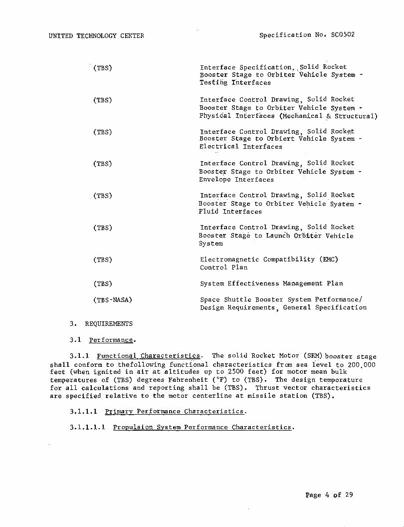
3• REQUIREMENTS
3.1 Performance.
Specification No. SC0502
Interface Specification, ,Solid RocketBooster Stage to Orbiter·Vehicle System Testing Interfaces
Interface Control Drawing, Solid RocketBooster Stage to Orbiter Vehicle System Physical Interfaces (Mechanical & Structural)
Interface Control Drawing, Solid Rock~t
Booster Stage to Orbiert Vehicle System Electrical Interfaces
Interface Control Drawing, Solid RocketBooste~ Stage to Orbiter Vehicle System Envelope Interfaces
Interf~ce Control Drawing, Solid RocketBooster Stage to Orbiter Vehicle System Fluid Interfaces
Interface Control Drawing, Solid RodketBooster Stag~ to LauncihOr6if~r VehicleSystem
Electromagnetic Compatibility (EMC)Control Plan
System Effectiveness Management Plan
Space Shuttle Booster System Performance/Design Requirements, General Specification
3.1.1 Functional Characterist~cs. The solid Rocket Motor (SRM) booster stageshall conform to thefollowing functional characteristics fr an sea level to 200. 000feet (when ignited in air at altitudes up to 2500 feet) for motor mean bulktemperatures of (TBS) degrees Fahrenheit (OF) to (TBS). The design temperaturefor all calculations and reporting shall be (TBS). Thrust vector characteristicsare specified relative to the motor centerline at missile station (TBS).
3.1.1.1 Primary Performance Characteristics.
3.1.1.1.1 Propulsion System Performance Characteristics.
Page 4 of 29
UNITED TECHNOLOGY CENTER Specification No. SC0502
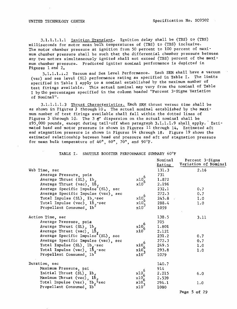
3.1.1.1.1.1 Ignition Transient. Ignition delay shall be (TBS) to (TBS)milliseconds for motor mean bulk temperatures of (TBS) to (TBS) inclusive.The motor chamber pressure at ignition from 50 percent to 100 percent of maximum chamber pressure shall be such that the differential chamber pressure betweenany two motors simultaneously ignited shall not exceed (TBS) percent of the maximum chamber pressure. Predicted igniter nominal performance is depicted inFigures 1 and 2.
3.1.1.1.1.2 Vacuum and Sea Level Performance. Each SRM shall have a vacuum(vac) and sea level (SL) performance rating as specified in Table I. The limitsspecified in Table I apply to a nominal established by the maximum number oftest firings available. This actual nominal may vary from the nominal of TableI by the percentages specified in the column headed "Percent 3-Sigma Variationof Nomina1".
3.1.1.1.1.3 Th~ust Characteristics. Each SRM thrust versus time shall beas shown in Figures 3 through 10. The actual nominal established by the maximum number of test firings available shall fall within the dotted lines ofFigut:"es 3 through 10. The 3 () dispersion on the actual nominal shall be±95,000 pounds, except during tail-off when paragraph 3.1.1.1.9 shall apply. Estimated head end motor pressure is shown in Figures 11 through 14. -Est-imated aftend stagnation pressure is shown in Figures 14 through 18. Figure 19 shows theestimated relationship between head end pressure and aft end stagnation pressurefor mean bulk temperature of 40° 60° 70° and 90°F., , ,
6xl06xlO
TABLE I. SHUTTLE BOOSTER PERFORMANCE SUMMARY 60°F
Nominal Percent 3-SigmaRating Variation of Nominal131.3 2.167311.8722.196232.1 0.7272.3 0.7245.8 1.0288.4 1.01059
Web Time, secAverage Pressure, psiaAverage Thrust (SL), 1bAverage Thrust (vac), l~fAverage Specific Impulse (SL), secAverage Specific Impulse (vac), secTotal Impulse (SL), lb -secTotal Impulse (vac) , l~f-secPropellant Consumed, Ib
Action Time, secAverage Pressure, psiaAverage Thrust (SL) , lbAverage Thrust (vac) , l~fAverage Specific Impulse (SL), secAverage Specific Impulse (vac), secTotal Impulse (SL), lb -secTotal Impulse (vac), l~f-secPropellant Consumed, lb
6xl06xlO
138.57051.8012.121231.2272.3249.5293.81079
3.11
0.70.71.01.0
Duration, secMaximum Pressure, psiInitial Thrust (SL), lbMaximum Thrust (vac), l~fTotal Impulse (vac) , lbf-secPropellant Consumed, lb
140.79142.2152.539294.11080
6.0
1.0
Page 5 of 29

UNITED TECHNOLOGY CENTER Specification No. SC0502
3.1.1.1.1.4 Maximum Expected Operating Chamber Pressure. The maximumexpected operating chamber pressure (MEOP) shall be 1,000 pounds per squareinch gage (psig)o
3.1.1.1.1.5 SRM Thrust Vector~ Solid rocket motor thrust performance isdefined for a motor whose nozzle centerline is coincident with the motor centerline. Alignment and movement of the thrust vector is defined in 3.1.1.1.2.
3.1.1.1.1.6 Stage Thrust Vector. Stage thrust vector performance isdefined for the thrust vector sum of the individual solid rocket motors. Thestage thrust vector location, alignment and movement is defined in 3.1.1.1.2relative to the stage centerline and to the intersection of the stage centerline with the stage/orbiter separation plane, MS (TBS).
3.1.1.1.1. 7 Nozzle Characteristics. (TBS)
3.1.1.1.1. 8 Propellant. (TBS)
3.1.1.1.1. 9 Thrust Decay (TBS)3.1.1.1.2 Primary Thrust Vector Control <TVC) System Performance
Characteristics. The TVC system shall provide the performance indicated belowduring stage operation under initial prelaunch temperature of 25°F to 100°F.The TVC system shall utilize moveable nozzles on each SRM to provide omni-axial thrust vector orientation in accordance with pitch, yaw, and roll commandsignals from the vehicle guidance system. The TVC performance of the individualSRMs and combined stage shall be as specified in the TVC Math Model,specification (TBS).
3.1.1.1.2.1 TVC System Operation. The stage TVC system shall consist ofomni-directional moveable nozzles. Each SRM shall have a single moveable nozzleoperated by two servo-controlled hydraulic actuators located in mutually perpendicular planes. The actuators shall position the SRM nozzles in accordance withpitch, yaw, and roll commands from the vehicle guidance system. Nozzle rotationshall be limited electronically to prevent overtravel in any axis. Controlaxes interactions and actuator cross coupling shall be defined' and compensationprOVided as required to obtain vehicle response in accordance with commandcontrol moments within the control variation defined herein.
3.1.1.1.2.2 Booster Stage Axes Definitiono Table II shows the stageaxes definition and indicates the command voltages and polarities required toprovide control moments about the roll, pitch, and yaw axes.
3.1.1.1.2.3 Stage Thrust Vectoringo The nominal stage pitch (yaw) thrustvector angle as a function of command voltage and nominal motor chamber pressureshall be as shown in Figure and described in the TVC Math Model, for allstage thrust vector angles between ±10 degrees.
3.1.1.1.2.4 Stage Thrust Vector Moment 'Arm. The nominal stage pitch(yaw) thrust vector moment arm as a function of command voltage and nominalmotor chamber pressure shall be as shown in Figure and as described in theTVC Math Model, for all thrust vector moment arms within ± (TBS) meters.
Page 6 of 29
UNITED TECHNOLOGY CENTER Specification No. SC0502
Table II. Axes Definition and Command Voltage.
_ ~+~/TCH
-.+YAW
CW~~CClA/
.";;'C/.. L
Booster SRM Axes Definition Loo~ing Forward
Command voltage relativeto its individualcorresponding return
-10 to + 10 volts on pitchcommand lines (threeredundant pairs)
-10 to + 10 volts on yawcommand lines (threeredundant pairs)
-10 to + 10 volts on rollcommand lines (threeredundant pairs)
,-------,--------------- --_.
Externallydirected force
Pitch of samepolarity as command
Yaw of samepolarity ascommand
Roll, cw for I'
+ commands andccw for - Icomman_d_s L
Page 7 of 29

UNITED TECHNOLOGY CENTER Specification No. SC0502,
3.1.1.1.2.5 TVC Hysteresis. Three-sigma deviations from nominal TVCrelationships in 3.1.1.1.2.3 and 3.1.1.1.2.4 due to command voltage reversalsshall not exceed the greater of ±(TBS)% or ±(TBS) degrees, or the greater of±(TBS)% or ±(TBS) inches, respectively, from ignition to web action time; andshall not exceed the greater of ±(TBS)% or ±(TBS) degrees, or ±(TBS)% or ±(TBS)inches, respectively, from web action time to action time.
3.1.1.1.2.6 TVC Variability. Three-sigma variability of the stage thrustvector angle shall not exceed the greater of ±(TBS)% or ±(TBS) degree, andvariability of the slope of the command voltage to thrust vector moment armrelationship shall not exceed the greater of ±(TBS)% or t(TBS) inches/volt fromignition to web action times; and shall not exceed ±(TBS) degrees, and thegreater of ±(TBS)% or ±(TBS) inches/volt, respectively, from web action time toaction time. This variability shall include all deviations, tolerances, andcross-coupling effects excepting variations in the nominal motor chamberpressure with stage mean bulk temperature.
3.1.1.1.2.7 Roll Control Moments. The nominal stage roll control momentas a function of roll command voltage and nominal motor chamber pressure shallbe as shown in Figure 22 and as described in the TVC Math Model. Three-sigmavariations shall not exceed the greater of ±(TBS)% or ±(TBS) Newton meters fromignition to web action time; or the greater of ±(TBS)% or ±(TBS) inch-poundsfrom web action time to action time. Three-sigma deviations from the nominalcommand voltage-to-roll control moment relationship due to command voltagereversal shall not exceed ±(TBS) inch-pounds from ignition to web action time;and ±(TBS) inch-pounds from web action time to action time.
3.1.1.1.2.8 Resolution. The TVC system resolution within the range of±10 degrees of SRM thrust vector angle shall not exceed (TBS) volts from ignitionto web action time and (TBS) volts from web action time to action time.
3.1.1.1.2.9 Frequency Response. The total thrust vector control systemfrequency response at any ambient voltage command level in the defined nozzleaxes for motor chamber pressures between (TBS) and (TBS) psia shall be as specifiedby the upper and lower limits of the amplitude ratio and phase lag given'inFigure 23. This curve is valid as long as the maximum command voltage does notexceed 10 VDC, the velocity or rate of change of the command voltage is belowthe minimum slew rates spectfied in Figure 24, and the minimum 'command is greaterthan (TBS) VDC.
3.1.1.1.2.10 Slew Rate. The TVC system shall be capable of changing thevehicle thrust vector angle at a minimum slew rate of 5 degrees per secondthroughout motor operating time. This requirement shall apply for all motorand actuation system operating conditions in conjunction with external nozzleloads and environments as specified in (TBS). Slew rate is defined as theinstantaneous rate of change of thrust vector angle for command changesexceeding (TBS) volts at a rate exceeding (TBS) volts per second. The minimumand maximum slew rate limits as a function of flight time shall be as shownin Figure 24. Minimum slew rate is derived assuming nominal SRM performancecombined with minus 3-sigma control system performance and plus 3-sigma externalnozzle loads. Maximum slew rates is derived assuming nominal SRM performancecombin~d with plus 3-sigma control system performance and minus 3-sigmaexternal nozzle loads.
Page 8 of 29

UNITED TECHNOLOGY CENTER Specification No. SC0502
3.1.1.1.3 SRM Ignition. Each SRM of the booster stage shall provide anintegral igniter motor that shall perform the function of initiating SRMignition. Simultaneous ignition of each SRM of the booster stage shall beaccomplished by receipt of simultaneous command signals, from the ,o~biter
or from ground equipment, to the ordnance electrical system of the SRM stage.
3.1.1.1.4 Staging Performance. The SRM booster stage shall providestaging ordnance in the form of linear shaped charges shall, upon commandfrom the orbiter vehicle, sever the booster stage from the launch vehicle atthe booster/orbiter 'interstage interface. Initiation of staging ignition shallbe accomplished by the SRM booster stage ordnance electrical system, uponcommand signal from the orbiter.
3.1.1.1.5 Flight Safety. To preclude or limit hazard to personnel and/orequipment, each SRM of the booster stage shall incorporate: 1) a thrust termination system with provisions for activation when commanded by the orbiter vehicleor upon detection of an inadvertent separation of an SRM from the launch vehicle,and, 2) an inadvertent separation detection system (ISDS), and 3) an emergencydetection system for monitoring critical booster ,parameters and providing signalsto the orbiter crew. The design of these sys.terns shall be in accordance withthe requirements of Range Safety Manual (TBS) , Shuttle Booster General SystemSpecification (TBS) and Component eEl Specifications.
3.1.1.1.5.1 Thrust Termination Performance. A two-port thrust terminationsystem shall be provided on each solid rocket motor. The thrust terminationsystem shall effectively neutralize the axial thrust of each SRM by venting thecombustion chamber at the forward end of each SRM. Each solid rocket motorand its thrust termination system shall be capable of surviving the environments created by thrust termination for a period of (TBS) seconds after theinitiation of thrust termination. The thrust termination performance for asingle solid rocket motor is shown in Figure 25.
3.1.1.1.5.2 Emergency Detection System. The emergency detectionsystem shall provide the following output signals to the orbiter •.
(a) Fast Failure: A signal shall be present when an emergencycondition exists which will result in motor failure with (TBD) secondsand an immediate abort is required.
(b) Slow Failure: A signal shall be present when an emergencycondition exists which will result in motor failure after at least(TBD) seconds from initial detection.
(c) Unverified Failure: A signal shall be present when anemergency condition is sensed by only one of a pair of redundant transducers.
Page 9 of 29

UNITED TECHNOLOGY CENTER Specification No. SC0502
Cd} . Emergency Detection System Self Check: a'signal shall bepresent when all Malfunction Detection System self check circuits areindicating proper olE ration.
An emergency detection system input shall be p!ovided such that thesystem can be disabled on command from the orbiter.
3.1.1.1. 5.3 Inadvertent Separation Detection System (ISDS). Each SRMof the booster stage shall provide an ISDS that shall detect the inadvertentloss of electrical cabling between the orbiter/launch vehicle and automaticallyinitiate thrust termination prior to receipt of a disable command from theorbiter. The ISDS shall be an integral part of the booster ordnan~e electricalsystem.
3.1.1.1.6 Electrical Power, Control, and Distribution. Each SRM of thebooster stage shall provide the airborne power, switching capability fromground power to airborne power, and the distribution of all airborne power tothe TVC system, ordnance system, emergency detection system, and flight instrumentation system. The electrical systems of the booster stage shall receive anddistribute ground power for SRM systems ground operation and checkout. Allsystems shall operate from 28 VDC (nominal) power sources.
3.1.1. 2 Secondary Performance Characteristics.
3.1.1.2.1 Instrumentation System Performance Characteristics. The boosterstage instrumentation system shall provide signal outputs to the orbiter for thepurpose of verification and evaluation of booster stage status and performanceprior to and during flight. The functional status of specified redundancyfeatures included in the other booster stage systems shall be indicated by discrete output signals to the orbiter.
3.1.1.2.2 Checkout Provisions. Provisions shall be made to allow thefollowing booster stage verification tests to be performed on an assembledlaunch vehicle via the airborne and ground electrical interfaces.
(a) Detailed functional tests, asspecified in(TBS~ of all electricaland mechanical subsystems including operational status of redundant features.
(b) System operability (quick look) tests, as specified in(TBS)of theflight critical active systems,providing go/no go signals, including checksof redundant features.
(c) Integrated-system test, as specified in(TBS~ performed as asimulated countdown and flight with the complete launch system.
(d) Booster stage component malfunction isolation and componentcheckout tests as specified in (TBS).
Page 10 of 29

UNITED TECHNOLOGY CENTER Specification No. SC0502
During these tests, airborne items which are not operated due to safety,one operation capability, reduced hold capability, or physical difficuity willbe checked in a non-operating mode to verify operable status and proper installation. No non-flight hardware will be connected to the stage for these testsexcept the normal ground umbilical cable.
3.1.1.2.3 Mass Property Requirements. Nominal values of mass, center ofgravity (cg) location, and momemnts of inertia shall be determined as a functionof flight characteristics. Three-sigma tolerances on the prelaunch values shallbe as follows:
cg location - longitudinalpitch planeyaw plane
Mass
Moments of inertia - ±10 percent
Individual SRMs
±7.7 inches±l. 6 inches±l. 7 inches
±3,600 pounds
±±±
±
The mass fraction of the stage shall be(TB~ minimum using the inch motor definition in Section 6.
3.1.1.2.4 Hold and Reaction Time Requirements. The booster stage shallbe capable of maintaining a launch hold at T-(TBS) minutes for 30 days withoutenvironmental protection (shall allow electrical maintenance of batteries viathe ground umbilical cable during the hold). The booster stage shall be capableof a launch reaction time of TBS hours after integrated system test and a systemabort recycle time for causes external to the vehicle of TBS hours. The boosterstage shall be capable of proceeding to T-(TBS) seconds returning to T-(TBS)minutes and holding for 30 days.
3.1.2 Operability. The SRM booster stage conform to the fol1owing·operabi1ityrequirements.
3.1.2.1 Reliability. The reliability of the SRM booster stage shall beas specified in the shuttle booster general system specification (TBS).
3.1.2.2 Maintainability. The SRM booster stage shall meet the maintainability requirements of MIL-STD-470. Quantitative requirements shall be established for the contributions to system downtime considering the AGE, facilities,and airborne portions of the vehicle system. The maintainability apportionmentshall be consistent with the probability of 1aunch-on-time requirements. Downtime shall be interpreted as active downtime defined in MIL-STD-778 and shallnot be greater than (TBS) hours mean active time to restore. Mean maintenancedowntime (M) is described for corrective-maintenance functions as:
Page 11 of 29

UNITED TECHNOLOGY CENTER
Where:
Nc
Specification No. SC0502
M = M hoursct
Nc
mean maintenance correction-time for sub-system(arithmetic mean)
number of corrective maintenance-functions formodular remove/replace maintenance concept
= active maintenance correction-time per correctivemaintenance task
The quantitative M allocations shall be as follows:
(TBS)
The M allocations do not apply on a lower level of assembly because maintenance or test results pertinent to a requirement for maintenance only occursat the fully assembled level. The above subsystems are defined in the UTCSystem Effectiveness Plan, (TBS).
3.1.2.2.1 Maintenance and Repair Cycles. Maintainability analyses shallestablish time goals for the completion of maintenance activities and the associated design and procedural approaches. This data will be incorporated intoequipment specifications and, thus, constitute objectives to be accomplishedduring the design process. Maintenance functions for support of the SRM arecorrective-maintenance functions. Preventive maintenance is not considered inthe maintenance concept.
3.1.2.2.2 Service and Access. Access shall be provided so all interfaceconnections and maintenance operations can be performed. The ordnance andTVC subsystems shall be capable of checkout and servicing while installed inthe "booster stage SRM. Access requirements shall be evaluated to ascertainperformance of corrective-maintenance tasks upon which active maintenancedowntime is based, and which are organizational level remove/replace maintanance functions.
Page 12 of 29

UNITED TECHNOLOGY CENTER Specification No. SCOS02
3.1.2.3 Useful Life. The SRM booster stage shall comply with shuttlebooster general system specification (TBS). The SRM booster stage shall meetthe requirements of this specification after exposure to the environmentspecified in 3.1.2.4 for a period of one year. Cyclic life limitations shallbe as defined in the component CEI specifications (see 3.3.1.3).
3.1.2.4 Environmental.
3.1.2.4.1 Prelaunch. The SRM booster stage shall perform as specifiedherein after exposure to the following environments.
(a) Temperature - Surrounding air temperatures between 25° and100°F with mean bulk propellant temperatures of 40° to 90°F for periodsup to 60 days.
(b) Humidity - Relative humidities of up to 100 percent includingcondensation in the form of water or frost for periods up to 60 days.
(c) Fungus - Exposure to fungi equivalent to 28 days of exposureto selected fungi as described in Specification MIL-E-S272. As, a designgoal materials which are fungus nutrients shall not be used.
(d) Sand and dust - Exposure to windblown graded sand and dust equivalent to exposure for 6 hours in a sand-and-dust chamber as described inSpecification MIL-E-S272.
(e) Sunshine - Normally exposed, non-metallic materials shallwithstand the deteriorating effects of direct sunlight for periods up to60 days.
(f) Salt fog - Exposure to salt fog equivalent to exposure to a20-percent salt spray for:
(i) 10 hours for internally-mounted equipment
(ii) SO hours for externally-mounted equipment
(g) Rain - Exposure to rain equivalent to 4 inches per hour for2 hours.
(h) Wind and gusts - Exposure to the wind and gusts prevalent atthe launch base as defined in (TBS).
(i) Propellant compatibility - (TBS)
(j) Loads - Exposure to loads induced by the winds and gusts specified in (h) above.
(k) Overpressure - Exposure to overpressures induced by an incidenton an adjacent launch pad as defined in (TBS).
Page 13 of 29
UNtTED TECHNOLOGY CENTER Specification SC0502
3.1.2.4.2 Launch and Flight. The SRM booster stage shall perform asspecified herein during and after exposure to the environment specified inthe shuttle booster general system specification (TBS).
3.1.2.4.3 Storage. The SRM booster stage shall perform as specifiedherein when its components CEls are stored at mean bulk temperatures between40°F and 90°F with propellant surfaces protected from humidity in excess of50 percent RH.
3.1.2.5 Transportability. The assembled SRM booster stage will not betransported. Transportation environments will be within the limits specifiedin 3.1.2.4. The forward section, segments, and aft section shall be transportable in the clevis-down or horizontal position without degradation of thepropellant or bonding to the extent that would preclude the booster stagefrom performing as specified herein. Component CEls shall be designed sothat only passive means of environmental protection are required during transportation.
3.1.2.6 Human Performance. The SRM booster stage and associated groundequipment shall meet the human-performance requirements of (TBS).
3.1.2.7 Safety.
3.1.2.7.1 Flight Safety. Design of airborne systems shall meet therequirements of applicable Range Safety Specification (TBS).
3.1.2.7.2 Ground Safety. The SRM shall be compatible with the shuttlebooster general specification (TBS).
Page 14 of 29

UNITED TECHNOLOGY CENTER Specification No. SC0502
3.1.2.7.3 Nuclear Safety. Not applicable.
3.1.2.7.4 Personnel Safety. Provisions for personnel safety shall bein accordance with the shuttle booster general specification (TBS).
3.1.2.7.5 Explosive and/or Ordnance Safety. The system shall comply wifuthe requirements of paragraph 3.1.2.7.4 of this CEI Specification and the shuttlebooster general specification (TBS) to the extent specified in the component CEISpecifications. The explosive classification of each assembled SRM of thebooster stage shall be Class 2 in accordance with AFM-127-l00.
3.2 CEI Definition.
3.2.1 Interface Requirements.
3.2.1.1 Schematic Arrangement. The SRM booster stage shall conform tothe dimensions shown in UTC Drawing (TBS): The schematic· arrangement of theo~~iill syst~m and each electrical system shall be as showri in Figures 26through 30 a~d UTC Drawing (TBS). .
3.2.1.2 Detailed Interface Definition.
3.2.1.2.1 System Interfaces. All interfaces between the SRM booster stageand the orbiter vehicle and facility will be defined and controlled by the following interface documents:
(TBS)
3.2.1.2.2 AGE Interfaces. Necessary interfaces for the SRM booster stagelaunch pad testing shall oe provided for mating with the following equipment:
(TBS)
3.2.2 Component Definition.
3.2.2.1 Customer-Furnished-Property List. The following items, whichare to be furnished by the customer, are required for flight CEI operation:
(a) Component CEIs (see 3.3.1.3) of each SRM
3.2.2.2 Engineering-Critical-Components List. Engineering criticalcomponents are listed in the component CEI specifications.
3.2.2.3 Logistics Critical Components List. Logistics critical componentsare listed in the component CEI specifications.
3.3 Design and Construction.
3.3.1 General Design Features.
3.3.1.1 General Design and Construction Requirements. The SRM designshall comply with the shuttle booster general system specification (TBS).
Page 15 of 29

UNITED TECHNOLOGY CENTER
3.3.1.2 Description.
Specification No. SC0502
3.3.1.2.1 Solid Rocket Booster Stage. The SRM booster stage shallconsist of three solid rocket motors attached together by their attach structure, interstage structure, and the various systems required by this specification. Each motor shall be a 3-segment l56-inch diameter motor with sphericalend closure at each end. The segments and closures are joined with a pressuresealing clevis joint. The attach structure also serves to collect the thrustand steering loads from each of the solid rocket motors and applies them tothe orbiter at the interstage structure.
3.3.1.2.2 Segments and Closures. Each segment is insulated with rubberand cast with composite, aluminized propellant in the form of a hollow cylinder.One end of the grain is restricted from burning by a rubber restrictor and atapering of the central perforation provides the required tailoff thrust characteristics. The forward closure is insulated with rubber and propellant is castin the form of an eight-point'star with ports provided to allow for thrusttermination. The aft closure is rubber insulated and has a circular port grainconfiguration.
3.3.1.2.3 Nozzle and Exit Cone. To the aft closure is attached a 50-inchdiameter ablative throat and a 20°-conical ablative exit cone with an expansionratio of 12.7:1.
3.3.1.2.4 Thrust Vector Control System. Thrust vector control is providedby moveable nozzles on each SRM. Each nozzle is supported by a constant-volumefluid-filled bearing which transmits the nozzle blowoff loads and thrust vectoring loads to the SRM by means of two annular rolling convolutes. Movement ofthe nozzle, within the limits of the fluid bearing, is provided by actuatorsplaced in mutually perpendicular planes. Hydraulic power for the actuators isprovided by a regulated pressure supply system using a solid propellant gasgenerator as the energy source. Actuator position control is accomplished byan electronic control unit, which resolves and conditions vehicle guidancesystem steering commands into the appropriate control responses.
3.3.1.2.5 Attach and Interstage Structures. The Attach Structure consistsof a thrust transmission structure and an aft skirt for each SRM. The aft skirtprovides ground support during buildup of a single SRM and ground support forthe assembled launch vehicle. The thrust transmission structure transmits theSRM thrust to the interstage structure described in UTC Specification (TBS).Provisions for mounting staging motors are provided in the thrust transmissionstructure and in the aft skirts. The interstage structure interfaces with theorbiter stage and includes the system required to separate the booster stageafter SRM burnout.
Page 16 of 29

UNITED TECHNOLOGY CENTER Specification No. SC0502
3.3.1.2.6 Emergency Detection System. Detection of impending SRMbooster failures necessitating a mission abort is provided by this system.The output of various pairs of redundant transducers are compared to predetermined criteria to determfue presence of an impending failure situation.Parallel redundancy is utilized in this system to reduce the possibility ofoccurrence of an inadvertent mission abort.
3.2.1.2.7 Instrumentation System. The instrumentation system shallmonitor pertinent booster stage parameters and supply conditioned signalsto the orbiter telemetry system to verify and evaluate booster stage statusand performance prior to and during flight. The system also provides signalinput and output via the ground umbilical cable, required to accomplishverification tests on the booster stage. The design of the instrumentationsystem component failure will result in performance degradation of any otherbooster stage system such that the limits of this specification are exceeded.
Page 17 of 29

UNITED TECHNOLOGY CENTER Specification No. SC0502
3.3.1.2.8 Ordnance System. The ordnance systems for the SRM boosterstage provided the capability of performing the functions of booster ignition,staging, thrust termination, and inadvertent separation detection by initiation of ordnance devices. The ordnance electrical system provides the powerand control of the firing units. Firing unit charging and triggering isaccomplished upon command from the orbiter vehicle or ground station.
3.3.1.2.9 Interstage Structure. The interstage structure shall transmitand distribute axial force, shear, and bending movement between the individualSRMs of the booster stage to the hydrogen-oxygen tank and shall provide sufficient separation between the SRM stage and the orbiter vehicle to allow SRMthrust termination port covers to clear the orbiter if the thrust terminationsystem is activated. The interstage structure shall provide an equipment bayfo~ housing some electrical components of the TVC, ordnance, emergency detectionand flight instrumentation systems. Provisions for compartment environmentalcontrol shall be made as necessary.
3.3.1.2.10 Redundancy. Redundancy shall be utilized, to the maximum extentpracticable, in all systems to exclude the possibility of a single non-structural failure causing out-of-specification performance.
3.3.1.2.11 Weight. The predicted component weights are given in table III.
3.3.1.3 Component CEls. The following sub-paragraphs identify thecomponent CEls which form each SRM of the booster stage.
3.3.1.3.1 Forward Section, Rocket Motor. Each booster forwardsection shall be in accordance with UTC Specification (TBS).
3.3.1.3.2 Aft Section, Rocket Motor. The booster aft sectionshall be in accordance with UTC Specification (TBS).
3.3.1.3.3 Segment Assembly, Rocket Motor. The booster segmentassembly shall be in accordance with UTC Specification (TBS).,
3.3.1.3.4 Nose Section, Rocket Motor. The booster nose sectionshall be in accordance with UTC Specification (TBS).
3.3.1.3.5 Extension, Nozzle Exit Cone. The nozzle exit cone extensionshall be in accordance with UTC Specification (TBS).
3.3.1.3.6 Battery Set. All flight batteries shall be in accordance withUTC Specification (TBS).
3.3.1.3.7 Ordnance Set, Rocket Motor. The booster ordnance setshall be in accordance with UTC Specification (TBS).
3.3.1.3.8 Mechanical Hardware Set, Rocket Motor. The boostermechanical hardware set shall be in accordance with UTC Specification (TBS).
3.3.1.3.9 Aft Structure, Rocket Motor. The booster aft sectionshall be in accordance with UTC Specification (TBS).
Page 18 of 29

UNITED TECHNOLOGY CENTER Specification No. SC0502
TABLE III. COMPONENT WEIGHTS
Component
Attach StructureForwardAft
Separation System
Solid Motor (Empty)Case
Forward ClosureSegments (Total)Aft ClosureAssembly Hardware
InsulationForward ClosureSegments (Total)Aft Closure
IgniterThrust TerminationNozzle
MoveableFixed
Actuation System
Electrical & Instrumentation
Weight Empty
Solid Propellant
Single Loaded Motor - Total
Interstage StructureStage Elect. '& Inst.
STAGE TOTAL
(15,850)3,250
12,600
(120,710)(85,358)18,37858,8367,744
400(15,257)
3,3428,5623,353
3782,043
(17,674)13,6314,043
1,080
634
138,274
1,080,000 ,
1,218,274
25,500905
3,681,227
Page 19 of 29
UNITED TECHNOLOGY CENTER Specification No. SC0502
3.3.1.3.10 Flight Instrumentation Set, Rocket Motor. The rocket motorflight instrumentation set shall be in accordance with UTC Specification (TBS).
3.3.1.3.11 Interstage Structure. The rocket motor Dooster interstage structureshall be in accordance with UTC Specification (TBS).
3.3.1 Selection of Specifications and Standards. ~he ie1ection ofspecifications and standards shall be in accordance with shuttle booster generalsystem specification (TBS).
3.3.3 Materials, Parts, and Processes. Materials, parts and processesused in e~h SRM shall conform to the applicable requirements as specified inshuttle booster' general system specification (TBS) as further defined by component CEI Specifications referenced in paragraph 3.3.1.
3.3.4 Standard and Commercial Parts. Standard and commercial parts shallbe in accordance with shuttle booster general system specification (TBS).
3.3.5 Moisture and Fungus Resistance. Materials used in this CEI shallcomply with the requirements of the shuttle booster general specification (TBS).
3.3.6 Corrosion of Metal Parts. All metal parts used in fabricationof the SRM shall be corrosion resistant or suitably treated to resist corrosionwhen exposed to the environmental conditions specified in 3.1.2.4. Whereverpractical, the use of dissimilar metals, as defined in Standard MS33586, incontact with each other shall be avoided.
3.3.7 Interchangeability and Replaceabi1ity. The interchangeability andrep1aceabi1ity, as specified in MIL-STD-447, of the SRM components shall be inaccordance ~ith MIL-I-8500.
3.3.8 Workmanship. The SRM shall be fabricated and finished in such amanner that criteria of appearnce, fit, and adherence to specified tolerancesshall be observed. Particular attention shall be given to' the neatness andthoroughness of soldering, wiring, marking of parts and assem~lies, plating,painting, riveting, machine-screw assemblage, welding and brazing, and freedomof parts from burrs and sharp edges.
3.3.9 Electromagnetic Interference. The SRM shall meet the electromagnetic interference requirements of Electromagnetic Compatibility ControlPlan (TBS).
3.3.10 Identification and Marking. The SRM shall be identified andmarked in accordance with MIL-STD-130 and (TBS).
~.~.11 Storage. The assembled SRM booster stage and its components shallconform to the storage requirements of 3.1.2.3 and 3.1.2.4, as applicable.
3.3.12 Cleanliness. The SRM booster stage and its ~omponents shallmeet the cleanliness requirements (TBS).
Page 20 of 29

UNITED TECHNOLOGY CENTER
4. QUALITY ASSURANCE PROVISIONS.
Specification No. SC0502
4.1 Category I Test. Category I tests as used herein shall be definedas contractor performed component, subsystem and full scale static leveltests. Records and documentation of results of all Category I testing shallbe maintained in comprehensive, legible format.
4.1.1 Engineering Test and Evaluation. Engineering tests and evaluations shall be conducted to provide maximum assurance of successful completion of the qualification and category II system tests specified below.
Page 21 of 29

UNITED TECHNOLOGY CENTER Specification No. SC0502
4.1.1.1 Development Testing. (TBS) motor firing tests shall be conducted at a UTC test facility during the development phase, (TBS) verticalat UTC and (TBS) horizontal thrust termination test. Motors shall be instrumented during these firings to evaluate the internal ballistic performance,TVC performance, and electrical system performance. Test configuration shallbe as specified in (TBS).
4.1.2 Pre1iminarv Oua1ification Tests. (TBS) rocket motors identicalin configuration to the final flight configuration will be fired in a preliminary flight rating test (PFRT) program to be conducted at a UTC testfacility. The differences in configuration will be limited to those requiredfor the inverted-from-f1ight attitude firings and are defined in (TBS).Successful completion of these firings will constitute the preliminary qualification test program.
4.1.3 Formal Qualification Tests. The following subparagraphs specifythe requirements for, and methods of, formally verifying that each requirement in Section 3 has been satisfied.
4.1.3.1 Inspection. The following requirements of Section 3 shall beverified by an inspection at a time and place to be determined mutually bythe customer and UTC: (TBS)
4.1.3.2 Analysis. Conformance to the following requirements shall beverified by comparative analysis of engineering documentation developed underprevious programs and during the testing of 4.1.1.1 and 4.1.2. No furthertesting will be conducted to verify conformance to these requirements. (TBS)
4.1.3.3 Demonstrations. Not applicable.
4.1.3.4 Tests. The following requirements in Section 3 shall be verifiedduring the preliminary qualification tests of 4.1.2: (TBS)
4.1.4 Reliability Tests and Analysis. At the start of the acquisitionphase a reliability mathematical model shall be presented to justify reliabilityfailure allocations for the various CEI components. The results of tests,failure reports, and conclusions as to system reliability shall be presented tothe customer throughout the acquisition program. No special testing shall bespecifically conducted to satisfy the provisions of 3.1.2.1.
4.1.5 Engineering Critical Component Qualification. Not applicable.
4.1.6. Interface Testing.
4.1.6.1 System Interfaces. Conformance to the requirement of paragraph3.2.1.2.1 "System Interface" shall be verified by comparative analysis ofengineering documentation developed under previous programs and during selectedtesting according to 4.1.1.1 and 4.1.2 as follows:
Page 12 of 'L'9

UNITED TECHNOLOGY CENTER Specification No. SC0502
4.1.6.1.1 Parametric Interfaces. SRM seal-level ballistic and TVC ,performance as specified in (TBS) shall be verified to the extent analyzed by 4.1. 3. 2and 4.1.3.4.
4.1.6.1.2 Structural and Dynamic Load Interfaces. These interfaces asspecified in (TBS), shall be verified only to the extent that mass propertyrequirements shall be verified as appropriate according to 4.1.3.2.
4.1. 6.1. 3 Electrical Interfaces. These interfaces as specified' in (TBS)shall be tested as defined by (TBS). (ref: 4.1.6.1.4)
4.1.6.1.4 Testing Interfaces. These interfaces, as specified in (TBS)shall be verified to the extent where UTC electrical test requirements areapplicable to the testing of 4.1.1.1 and 4.1.2. (reference 4.1.6.1.8 forfluid systems verifications.)
4.1.6.1.5 Physical Interfaces. Dimensional requirements only, as specifiedin (TBS), shall be verified according to the inspections of 4.1.3.1.
4.1.6.1.6 Electrical Interfaces., These interfaces, as specified in (TBS),shall be verified by testing as defined by (TBS). (ref.: 4.1.6.1.4)
4.1.6.1.7 Envelope Interface. Dimensional requirements only, as specifiedin (TBS), shall be verified according to the inspections of 4.1.3.1.
4.1.6.1.8 Fluid Interfaces. To the extent that the fluid interfaces arerequired for the testing of 4.1.1.1 and 4.1.2, the interfaces (mechanical,fluid quantity and fluid quality) used for static test will be consistent withthe requirements of (TBS) and thereby verify adequacy of requirements.
4.1.6.1.9 Installation Interfaces. Dimensional requirements only, asspecified in (TBS), shall be verified according to the inspections of 4.1.3.1.
4.2 Category II Test Program. The requirements of 3.3.9 shall be verifiedby tests to be performed after the SRM stage has been integrated'into an assembledlaunch vehicle. The solid rocket motors shall demonstrate the following minimumvehicle centerline vacuum web action time total impulse when assembled andlaunched as a Stage of the space shuttle launch vehicle in accordance withMIL-STD-47l: (TBS)
5. PREPARATION FOR DELIVERY. (TBS)
6. NOTES.
6.1 Supplemental Information. Maximum use shall be made of componentsqualified under other programs.
6.1.1 Definitions. For purposes of this specification the followingdefinitions shall apply:
Page-23 of 29

UNITED TECHNOLOGY CENTER Specification No. SC0502
6.1.1.1 Web Action Time. Web action time shall be defined as follows:The start of web action time shall be that point in the pressure/time traceat which the head end pressure has reached 75 percent of maximum. The end ofweb action time shall be defined by the following geomAtric construction.Extend the general shape of the pressure time curve prior to and immediatelyafter the beginning of tail-off. Then bisect the angle formed by this extension.Extend this bisector to intersect the pressure/time trace. The time that corresponds to this intersection point is the end of web action time.
6.1.1.2 Action Time. Action time is defined as beginning when the pressure has risen to 75 percent of the maximum chamber pressure and ending whenthe head end pressure has fallen to 10 percent of the maximum chamber pressure.
6.1.1.3 Delivered Specific Impulse. The delivered specific impulse shallbe defined as the total impulse along the nozzle centerline delivered duringweb action time divided by the weight of propellant expended during web actiontime. Delivered specific impulse at plant site shall -be extrapolated to specificimpulse at vacuum conditions. The methods used to determine the weight of expended prope1lan~ and to extrapolate the data shall be presented subject tocustomer approval.
6.1.1.4 Regressivity. Regressivity is defined as the maximum vacuumthrust minus the vacuum thrust at end of web action time divided by the maximumvacuum thrust. All thrusts are taken along the noz~le centerline.
6.1.1.5 Action Time Total Impulse. Action time total impulse is definedas the integrated thrust along the nozzle centerline over the action time.
6.1.1.6 Initial Vacuum Thrust. Initial vacuum thrust is defined as thatvacuum thrust along with the nozzle centerline at the completion of ignition.Initial vacuum thrust may be calculated from sea level data by adding 183,60~ 1b
fto the measured sea level nozzle centerline thrust.
6.1.1.7 Web Action Time Total Impulse. Web action time total impulse isdefined as the integrated thrust along the nozzle centerline over the web actiontime.
6.1.1.8 Ignition Delay. Ignition delay is defined as the time intervalbetween fire signal and when the motor chamber pressure reaches 75 percent ofthe initial peak pressure.
6.1.1.9 Tai1off. Tai10ff is defined as the time interval between webaction time and action time.
6.1.1.10 Total Prelaunch Weight (Nominal). Total prelaunch weight isdefined as the. sum of all motor weights which includes propellants and inerts.
6.1.1.11 Expendable Weight. Expendable weight is defined as the weightof those items that are expended from the motor which include propellant, insulation and liner, nozzle, igniter charge, and weather seal.
Pa ge 24 of -29

UNITED TECHNOLOGY CENTER Specification No. SC0502
6.1.1.12 Weight Empty. Weight empty is defined as the total of inertmotor component weights excluding R&D instrumentation.
6. L L 13 Burnout Motor Weight. Total prelaunch 'veight minus expendablesis burnout condition. A definition of burnout weight is prelaunch weightminus inert expendable weight excluding expended propellant and igniter chargeweight.
601.1.14 Loaded Propellant Weight. Loaded propellant weight is definedas all solid propellant weight in the rocket motor.
6.1.1.15 Nominal Inert Motor Weight. Nominal inert motor weight includesthe following: The motor case with nozzle, thrust termination port covers andstacks
tskirts, igniter, and internal insulation. It does not include the TVC
system and its attachments, instrumentation, ordnance system, power supplies.,other electrical systems, external insulation, all vehicle attachment and aerodynamic fairings.
6.1.1.16 Mass Fraction. The nominal propellant mass fraction (~p) isdetermined by the following method:
~p = W / (W + W.)P P ~
Where: W = Loaded Propellant Weightp
W. = Nominal Inert Motor Weight~
6.1.1.17 Resolution. Resolution is defined as the m~n~mum change in inputvoltage necessary to produce a change in generated side force, in the same direction as the previous change.
6.1.1.18 Hysteresis. Hysteresis is defined as the difference in inputvoltage required to produce a change in generated thrust vector moment arm(TVMA) when the direction of the TVMA is changed due to command voltage reversals.
6.1.1.19 Deflection Angle. Deflection angle is defined as the arctan ofthe side thrust measured perpendicular to the nozzle centerline divided by theaxial thrust measured along the nozzle centerline.
6.1.1.20 Launch Reaction Time. Launch reaction time is defined as thetime required to prepare to launch a vehicle following the completion of prelaunch checkout.
6.1.1.21 Abort Recycle Time. Abort recycle time is defined as the timerequired to launch a vehicle following an abortive launch attempt.
6.1.1.22 The SRM Pitch (Yaw) Thrust Vector Angle. The angle between theSRM motor centerline and the projection of the SRM thrust vector into theSRM pitch (yaw) plane.
Page 25 of 29

UNITED TECHNOLOGY CENTER Specification No. SCOS02
6.1.1.23 SRM Pitch (Yaw) Plane. The plane .defined by the SRM motorcenterline and a line which is normal to the SRM centerline and parallel tothe vehicle pitch (yaw) plane.
6.1.1.24 The SRM Pitch (Yaw) Thrust Vector Moment Arm. The length ofthe perpendicular line from the SRM motor centerline at missle station (TBS)to the SRM projection of the thrust vector into the pitch (yaw) plane.
6.1.1.25 Solid Rocket Motor Centerline. The line joining the centerof the aft closure-to-nozzle throat bolt circle to the center of the forwardclosure in the plane of the forward attach structure.
6.1.1.26 Nozzle Centerline. The line joining the center of the nozzlethroat to the center of the nozzle exit.
6.1.1.27 Stage Centerline. The line Jo~n~ng the center of the stage!orbiter a~semb1y joint bolt circle and the center of the aft structure supportstructure.
6.1.1.28 SRM Thrust Vector. The force vector whose magnitude and variability is defined by paragraph 3.1.1.1.1, and whose direction and variabilityis defined by paragraph 3.1.1.1.2.
6.1.1.29 Stage Roll Plane. A plane perpendicular to the stage centerline.which intersects the stage centerline at missile station (TBS).
6.1.1.30 Stage Roll Control Moment. The resultant moment about the stagecenterline of the sum of the SRM thrust vectors projected into the stage rollplane.
Page 26 of 29
UNITED TECHNOLOGY CENTER
10. APPENDIX
Specification No. SC0502
10.1 Test Configuration. The static test configuration of the SRM shallconform to UTC drawing (TBS). This drawing shows seve~al obvious differencesfrom the flight configuration. These differences shall not affect ?erformancebut are related to ordance, structural, and instrumentation measurements whichpertain directly to the static test program.
Specific differences shall include the following areas: (TBS)
Page 27 of 29
UNITED TECHNOLOGY CENTER
The following figures are to be supplied:
Specification No. SC0502
Figure 1. Ignition Transient l56-Inch Thrust Versus Time & NozzleSea Level at 60°F
Figure 2. Ignition Transient l56-Inch Pressure Versus Time at 60°F
Figure 3. Vacuum Thrust Versus Time, 40°F
Figure 4. Vacuum Thrust Versus Time, 60°F
Figure 5. Vacuum Thrust Versus Time, 70°F
Figure 6. Vacuum Thrust Versus Time, 90°F
Figure 7. Sea Level Thrust Versus Time, 40°F
Figure 8. Sea Level Thrust Versus Time, 60°F
Figure 9. Sea Level Thrust Versus Time, 70°F
Figure 10. Sea Level Thrust Versus Time, 90°F
Figure 11. Forward Head Pressure Versus Time, 40°F
Figure 12. Forward Head Pressure Versus Time, 60°F
Figure 13. Forward Head Pressure Versus Time, 70°F
Figure 14. Forward Head Pressure Versus Time, 90°F
Figure 15. Aft End Pressure Versus Time, 40°F
Figure 16. Aft End Pressure Ver~us Time, 60°F
Figure 17. Aft End Pressure Versus Time, 70°F
Figure 18. Aft End Pressure Versus Time, 90°F
Figure 19. Aft to Forward Head Pressure Ratio Versus Time
Figure 20. Thrust Vector Angle Versus Command Voltage andChamber Pressure
Figure 21. Thrust Vector Moment Arm Versus Command Voltageand Nominal Chamber Pressure
Figure 22. Roll Control Moment Versus Roll Command Voltageand Nominal Chamber Pressure
Page 28 of 29
UNITED TECHNOLOGY CENTER Specification No. SC0502
Figure 23. Frequency Response
Figure 24. Slew Rates
Figure 25. Net Thrust Versus Time from Thrust Termination Actuation
Figures 26 through 30. Schematic Arrangements of SRM Electrical Systems
Page 29' of 2~f
UNITED TECHNOLOGY CENTER
PRELIMINARY
Specification No. SC0503
PRIME ITEM DEVELOPMENT SPECIFICATION
ROCKET MOTOR, SPACE SHUTTLE BOOSTER, P4-l20
Basic Approved by~~,__~__~~ ___(United Technology Center)
Date, _
Basic Approved by _
Date, _
Page 1 of 27

UNITED TECHNOLOGY CENTER Specification No o SC0503
1. SCOPE. This specification estab1~shes the performance, design,development, and test requirements for the P4-120 space shuttle booster'rocketmotor prime item.
2. APPLICABLE DOCUMENTS. The following documents form a part of thisspecification to the extent specified herein. In the event of conflict betweendocumert~.s refe~enced here and the contents of this specification, the contentsof this specification shall be considered a superseding requirement.
SPECIFICATIONS
Military
MIL-E-5272
MIL-H-6083
MIL-I-8500
United Technology Center
(TBS)
(TBS)
(TBS)
(TBS)
(TBS)
(TBS)
(TBS)
(TBS)
(TBS)
(TBS)
(TBS)
Environmental Testing, Aeronautical andAssociated Equipment, General Specification
Hydraulic Fluid., Petroleum Base,Preservative
Interchangeability and Rep1aceabilityof Component Parts for Aircraft andMissiles
Forward Section, Rocket Motor
Mechanical Hardware Set, Rocket Motor
Ordnance Set, Rocket Motor
Segment AssemblY, Rocket Motor
Aft Section, Rocket Motor
Extension, Nozzle Exit Cone
Nose Section, Rocket Motor
Aft Structure, Rocket Motor
Interstage Structure
Flight Instrumentation Set, Rocket Motor
Battery Set
Page 2 of 27
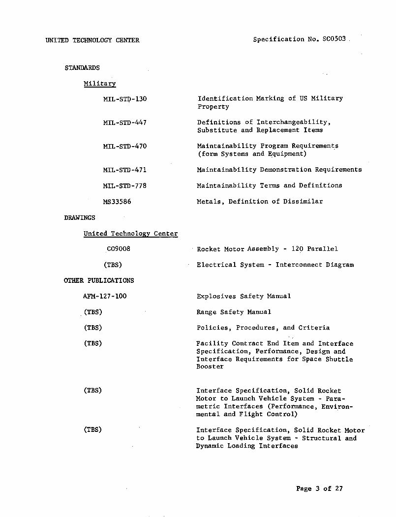
UNITED TECHNOLOGY CENTER
STANDARDS
Military
MIL-STI;l-130
MIL-STD-447
MIL-STD-470
MIL-STD-471
MIL-STD-778
MS33586
DRAWINGS
United Technology Center
C09008
(TBS)
OTHER PUBLICATIONS
AFM-l27-l00
, (TBS)
(TBS)
(TBS)
(TBS)
(TBS)
Specification No. SC0503 ,
Identification Marking of US MilitaryProperty
Definitions of Interchangeability,Substitute and Replacement Items
Maintainability Program Requirements(form Systems and Equipment) .
Maintainability Demonstration Requirements
Maintainability Terms and Definitions
Metals, Definition of Dissimilar
Rocket Motor Assembly - 120 Parallel
Electrical System - Interconnect Diagram
Explosives Safety Manual
Range Safety Manual
Policies, Procedures, and Criteria
Facility Contract End Item and InterfaceSpecification, Performance, Design andInterface Requirements for Space ShuttleBooster
Interface Specification, Solid RocketMotor to Launch Vehicle System - Parametric Interfaces (Performance, Environmental and Flight Control)
Interface Specification, Solid Rocket Motorto Launch Vehicle System - Structural andDynamic Loading Interfaces
Page 3 of 27

UNITED TECHNOLOGY CENTER
(TBS)
(TBS)
(TBS)
(TBS)
(TBS)
(TBS)
(TBS)
(TBS)
(TBS)
(TBS) (NASA)
3. REQUIREMENTS
3.1 Performance
Specification No. SC0503 .
Interface Specification, Solid RocketMotor to Launch Vehicle System,Electrical Interfaces
Interface Specification, Solid RocketMotor to Launch Vehicle System - TestingInterfaces
Interface Control Drawing, Solid RocketMotor to Launch Vehicle System - PhysicalInterfaces (Mechanical and Structural)
Interface Control Drawing, Solid RocketMotor to Launch Vehicle System - ElectricalInterfaces
Interface Control Drawing, Solid RocketMotor to Launch Vehicle System - EnvelopeInterfaces
Interface Control Drawing, Solid RocketMotor to Launch Vehicle System - FluidInterfaces
Interface Control Drawing, Solid RocketMotor to Launch Vehicle System - Installation Interfaces
Electromagnetic Compatibility (EMC)Control Plan
System Effectiveness Management Plan
Space Shuttle Booster System Performance/Design Requirements, General Specification
3.1.1 Functional Characteristics. The solid rocket motor (SRM) shallconform to the following functional characteristics from sea level to 200,000feet (when ignited in air at altitudes ug to 2500 feet) for motor mean bulktemperatures of (TBS) degrees Fahrenheit ( F) to(TBS). The design temperaturefor all calculations and reporting shall be(TBS~ Thrust vector characteristicsare specified relative to the motor centerline at missile station (TBS).
3.1.1.1 Primary Performance Characteristics.
3.1.1.1.1 Propulsion System Performance Characteristics.
Page 4 of 27

UNITED TECHNOLOGY CENTER Specification No. SC0503
3.1.1.1.1.1 Ignition Transient. Ignition delay shall be TBS to TBS milliseconds for motor mean bulk temperatures of (TBS)OF to (TBS)OF inclusive. Themotor chamber pressure at ignition from 50 percent to 100 percent of maximumchamber pressure shall be such that the differential chamber pressure betweenany two motors simultane9us1y ignited shall not exceed TBS percent of the maximumchamber pressure. Predicted igniter nominal performance is depicted inFigures 1 and 2.
3.1.1.1.1.2 Vacuum and Sea Level Performance. The SRM shall have avacuum and sea level performance rating as indicated in Table I. The limitsspecified in Table I apply to a nominal established by the maximum number oftest firings available. This actual nominal may vary from the nominal of Table Iby the percentages specified in the column headed "Percent 3-sigma Variation ofNominal" .
3.1.1.1.1.3 Thrust Characteristics. The SRM thrust versus time shall beas shown in Figures 3 through 10. The actual nominal established by the maximumnumber o:E test firings available shall fall within the .dotted lines of Figures 3through 10 .. The 3~ dispersion on the actual nominal shall be ± 95,000 pounds,except during tail-off when paragraph 3.1.1.1.1.9 shall apply. Estimated headend mot04 pressure is shown in Figures 11 through 14. Estimated,aft endstagnation pressure ~s shown in Figures 14 through 18. Figure 19 shows theestimated relationship between head end pressure and aft end stagnation pressurefor mean bulk temperature of 40°, 60°, 70°, and 90°F.
Table I. Shuttle Booster Performance Summary60°F
NominalRating
Web Time, sec 128.3Average Pressure, psia 514Average Thrust (SL) , 1bf x106 0.991Average Thrust (vac), 1bf x106 1.172Average Specific Impulse (SL), sec 227.0Average Specific Impulse (vac) , sec 268.5Total Impulse (SL) , 1bf-sec x106 127.2Total Impulse (vac), 1bf-sec x106 150.4Propellant Consumed, 1b x103 560.2
Ac t ion Time, sec 140.2Average Pressure, psia 496Average Thrust (SL) , 1bf x106 0.952Average Thrust (vac), 1bf x106 1.131Average Specific Impulse (SL), sec 225.8Average Specific Impulse (vac) , sec 268.5Total Impulse (SL) , 1bf -sec x106 133.5Total Impulse (vac), 1bf-sec x106 158.6Propellant Consumed, 1b x103 591.0
Percent 3-SigmaVariationof Nominal
2.16
0.70.71.01.0
3.11
0.70.71.01.0
Page 5 of 27

UNITED TECHNOLOGY CENTER Specification No. SC0503
Duration, secMaximum Pressure, psiInitial Thrust (SL) , 1bfMaximum Thrust (vac), 1bfTotal Impulse (vac), 1bf-secPropellant Consumed, 1b
x106
x106x106x103
NominalRating
142.0837
1.4311.615158.9591.8
Percent 3-SigmaVariationsof Nominal
6.0
1.0
3.1.1.1.1.4 Maximum Expected Operating Chamber Pressure. The maximumexpected operating chamber pressure (MEOP) shall be 1000 pounds per square inchgage (ps ig) .
3.1.1.1.1.5 SRM Thrust Vector. Solid rocket motor thruat vector performance is defined for a motor whose nozzle centerline is coincident with the motorcenterline. Alignment and movement of the thrust vector is defined in paragraph 3.1.1~1.2.
3.1.1.1.1.6 Stage Thrust Vector. Stage thrust vector performance isdefined for the thrust vector sum of the individual solid rocket motors. Thestage thrust vector location, alignment and movement is defined in 3.1.1.2relative to the stage centerline and to the intersection of the stage centerlinewith the stage/orbiter separation plane, MS (TBS).
3.1.1.1.1.7 Nozzle Characteristics. (TBS)
3.1.1.1.1.8 Propellant. (TBS)
3.1.1.1.1.9 Thrust Decay. (TBS)
3.1.1.1.2 Primary Thrust Vector Control (TVC) System Performance Characteristics. The TVC system shall provide the performance indicated below duringstage operation under initial pre-launch temperatures of 25°F to 100°F. TheTVC system shall utilize movable nozzles on each SRM to provide ,omniaxia1 thrustvector orientation in accordance with pitch, yaw, and roll command signals fromthe vehicle guidance system. The TVC performance of the individual SRMS shallbe as specified in the TVC Math. Model Specification (TBS).
3.1.1.1.2.1 TVC System Operation. The stage TVC system shall consist ofomni-directiona1 movable nozzles. Each SRM shall have a single movable nozzleoperated by two servo-controlled hydraulic actuators located in mutually perpendicular planes. The actuators shall position the SRM nozzles in accordancewith pitch, yaw, and roll commands from the vehicle guidance system. Nozzlerotation shall be limited electronically to prevent overtrave1 in any axis.Control axes interactions and actuator cross-coupling shall be defined andcompensation provided as required to obtain vehicle response in accordancewith command control moments and within the control variations defined herein.
3.1.1.1.2.2and indicates themoments about the
SRM Axes Definition.command voltages androll, pitch, and yaw
Table II shows the SRM axes definitionpolarities required to provide controlaxes.
Page 6 of 27

UNITED TECHNOLOGY CENTER Specification No. SC0503
Table II. Axes Definition and Command Voltage
+Pitch
.......-+--1.... +Yaw
cw~CCW~ROIT -
Booster SRM Axes Definition Looking Forward
Command Voltage Relativeto its individual correspondingreturn
+--------------------t--10 to +10 volts on pitchcommand lines (three redundantpairs)
-10 to +10 volts on yawcommand lines (three redundantpairs)
-10 to +10 volts on rollcommand lines (three redundantpairs)
Externally Directed Force
Pitch of same polarity ascommand
Yaw of same polarity ascommand
Roll CW for (+) commands andCCW for (-) commands
3.1.1.1.2.3 SRM Thrust Vectoring. The nominal SRM pitch (yaw) thrustvector angle, as a function of command voltage and nominal motor chamber pressure,shall be as shown in Figure 20 and as described in the TVC Math. Model, for allSRM thrust vector angles between flO degrees.
3.1.1.1.2.4 SRM Thrust Vector Moment Arm. The nominal SRM pitch (yaw)thrust vector moment arm as a function of command voltage and nominal motorchamber pressure shall be as shown in Figure 21 and as described in the TVCMath. Model, for all thrust vector moment arms within ± (TBS)inches.
Page 7 of 27
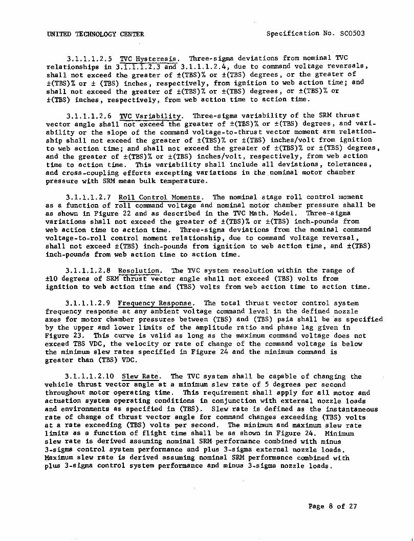
UNITED TECHNOLOGY CENTER Specification No. SC0503
3.1.1.1.2.5 TVC Hysteresis. Three-sigma deviations from nominal TVCrelationships in 3.1.1.1.2.3 and 3.1.1.1.2.4, due to command voltage reversals,shall not exceed the greater of ±(TBS)% or ±(TBS) degrees, or the greater of±(TBS)% or ± (TBS) inches, respectively, from ignition to web action time; andshall not exceed the greater of ±(TBS)% or ±(TBS) degrees, or ±(TBS)% or±(TBS) inches, respectively, from web action time to action time.
3.1.1.1.2.6 TVC Variability. Three-sigma variability of the SRM thrustvector angle shall not exceed the greater of ±(TBS)% or ±(TBS) degrees, and variability or the slope of the command voltage-to-thrust vector moment arm relationship sh.all not exceed the greater of ±(TBS)% or ±(TBS) inches/volt from ignitionto web action time; and shall not exceed the greater of ±(TBS)% or ±(TBS) degrees,and the greater of ±(TBS)% or ±(TBS) inches/volt, respectively, from web actiontime to action time. This variability shall include all deviations, tolerances,and cross-coupling efforts excepting variations in the.nominal motor chamberpressure with SRM mean bulk temperature.
3.1.1.1.2.7 Roll Control Moments. The nominal stage roll control momentas a function of roll command voltage and nominal motor chamber pressure shall beas shown in Figure 22 and as described in the TVC Math. Model. Three-sigmavariations shall not exceed the greater of ±(TBS)% or ±(TBS) inch-pounds fromweb action time to action time. Three-sigma deviations from the nominal commandvoltage-to-roll control moment relationship, due to command voltage reversal,shall not exceed ±(TBS) inch-pounds from ignition to web action time, and ±(TBS)inch-pounds from web action time to action time.
3.1.1.1.2.8 Resolution. The TVC system resolution within the range of±10 degrees of SRM thrust vector angle shall not exceed (TBS) volts fromignition to web action time and (TBS) volts from web action time to action time.
3.1.1.1.2.9 Frequency Response. The total thrust vector control systemfrequency response at any ambient voltage command level in the defined nozzleaxes for motor chamber pressures between (TBS) and (TBS) psia shall be as specifiedby the upper and lower limits of the amplitude ratio and phase lag given inFigure 23. This curve is valid as long as the maximum command voltage does notexceed TBS VDC, the velocity or rate of change of the command voltage is belowthe minimum slew rates specified in Figure 24 and the minimum command isgreater than (TBS) VDC.
3.1.1.1.2.10 Slew Rate. The TVC system shall be capable of changing thevehicle thrust vector angle at a minimum slew rate of 5 degrees per secondthroughout motor operating time. This requirement shall apply for all motor andactuation system operating conditions in conjunction with external nozzle loadsand environments as specified in (TBS). Slew rate is defined as the instantaneousrate of change of thrust vector angle for command changes exceeding (TBS) voltsat a rate exceeding (TBS) volts per second. The minimum and maximum slew ratelimits as a function of flight time shall be as shown in Figure 24. Minimumslew rate is derived assuming nominal SRM performance combined with minus3-sigma control system performance and plus 3-sigma external nozzle loads.Maximum slew rate is derived assuming nominal SRM performance combined withplus 3-sigma control system performance and minus 3-sigma nozzle loads.
Page 8 of 27

UNITED TECHNOLOGY CENTER Specification No. SC0503
3.1.1.1.3 SRM Ignition. Each SRM of the booster stage shall provide anintegral igniter motor that shall perform the function of initiating SRM ignition.Simultaneous ignition initiation of each SRM of the booster stage shall beaccomplished by receipt of simultaneous command signals from the orbiter or fromground equipment to the ordnance electrical system of each SRM.
3.1.1.1.4 Staging Performance. (TBS) staging motors per SRM, (TBS) inthe nose section, and (TBS) in the aft section shall supply the lateral stagingimpulse to each SRM to fulfill the requirements of the shuttle booster generalsystems specification (TBS). Staging ignition initiation shall be accomplishedby the SRM ordnance electrical system upon receipt of command from the orbiter.
3.1.1.1.5 Flight Safety. To preclude or limit hazard to personnel and/orequipment, each SRM of the booster stage shall incorporate: (1) a thrusttermination system with provisions for activation when commanded by the orbitervehicle or upon detection of an inadvertent separation of an SRM from the launchvehicle, and (2) an inadvertent separation detection system (ISDS), and (3) anemergency detection system for monitoring critical booster parameters and providing signals to the orbiter crew. The design of these systems shall be in accordance with the requirements of Range Safety (TBS) Shuttle Booster General SystemSpecification (TBS) and Component CEI Specifications.
3.1.1.1.5.1 Thrust Termination Performance. A two-port thrust terminationsystem shall be provided on each solid rocket motor. The thrust terminationsystem shall effectively neutralize the axial thrust of each SRM by ventingthe combustion chamber at the forward end of each SRM. Each solid rocket motorand its thrust termination system shall be capable of surviving the environmentscreated by thrus't termination for a period of (TBS) seconds after the initiationof thrust termination. The thrust termination performance for a single solidrocket motor is shown in Figure 25.
3.1.1.1.5.2 Emergency Detection System. The emergency detection systemshall provide the following output signals to the orbiter:
(a) Fast Failure: A signal shall be present when an emergencycondition exists which will result in motor failure within (TBS)seconds and an immediate abort is required;
(b) Slow Failure: A signal shall be present when an emergencycondition exists which will result in motor failure after atleast (TBS) seconds from initial detection;
(c) Unverfied Failure: A signal shall be present when an emergencycondition is sensed by only one of a pair of redundant transducers;
(d) Emergency Detection System Self Check: A signal shall bepresent when all malfunction detection system self-check circuitsare indicating proper operation.
An emergency detection system input shall be provided such that the system canbe disabled on command from the orbiter.
Page 9 of 27

UNITED TECHNOLOGY CENTER Specification No. SC0503
3.1.1.1.5.3 Inadvertent Separation Detection System (ISDS). Each SRM ofthe booster stage shall provide an ISDS that shall detect the inadvertent lossof electrical cabling between the orbiter/launch vehicle and automaticallyini~iate thrust termination prior to receipt of a disable command from theorbiter. The ISDS shall be an integral part of the SRM ordnance electricalsystem.
3.1.1.1.6 Electrical Power, Control, and Distribution. Each SRM of thebooster stage shall provide the airborne power, switching capability from groundpower to airborne power, and the distribution of all airborne power to the TVCsystem, ordnance system, emergency detection system, and flight instrumentationsystem. Each SRM of the booster stage shall receive and distribute groundpower for SRM systems ground operation and checkout. All systems shall operatefrom 28 VDC (nominal) power sources.
3.1.1.2 Secondary Performance Characteristics.
3.1.1.2.1 Instrumentation System Performance Characteristics. The boosterstage instrumentation system shall provide signal outputs to the orbiter for thepurpose of verification and evaluation of booster stage status and performanceprior to and during flight. The functional status of specified redundancyfeatures included in the other booster stage systems shall be indicated by·discrete output signals to the orbiter.
3.1.1.2.2 Checkout Provisions. Provisions shall be made to allow thefollowing booster stage verification tests to be performed on an assembledlaunch vehicle via the airborne and ground electrical interfaces.
(a) Detailed functional tes ts, as specified in (TBS) , of all electricaland mechanical subsystems, including operational status of redundantfeatures.
(b) System operability (quick-look) tests, as specified in (TBS) of theflight critical active systems, providing go/no go signals, includingchecks of redundant features.
(c) Integrated-system test, as specified in (TBS), performed as asimulated countdown and flight with the complete launch system.
(d) Booster stage component malfunction isolation and component checkouttests as specified in (TBS).
During these tests, airborne items which are not operated due to safety, oneoperation capability, reduced hold capability, or physical difficulty will bechecked in a non-operating mode to verify operable status and proper installation. No nonf1ight hardware will be connected to the stage for these testsexcept the normal ground umbilical cable.
3.1.1.2.3 Mass Property Requirements. Nominal values of mass, center ofgravity (cg) 10cation,and moments of inertia shall be determined as a functionof flight characteristics. Three sigma tolerances on the prelaunch values shallbe as follows:
Page 10 of 27

UNITED TECHNOLOGY CENTER Specification No. SC0503
Individual SRMs Stage
cg location - longitudinal ±7.7 inches +pitch plane ±1.6 inches +yaw plane ±1.7 inches +
BS)Mass ±3,600 pounds +
Moments of inertia ±10 percent +
The mass fraction of the motor shall be(TBS) minimum using the "inert"motor definition in Section 6.
3.1.1.2.4 Hold and Reaction Time Reguirements. The booster stage shallbe capable of maintaining a launch hold at T-(TBS) minutes for 30 days withoutenvironmental protection (shall allow electrical maintenance of batteries viathe ground umbilical cable during the hold). The booster stage shall be capableof a launch reaction time of(TBS)hours after integrated system test and a systemabort recycle time for causes external to the vehicle of TBS hours. The boosterstage shall be capable of proceeding to T-(TBS) seconds returning to T-(TBS)minutes and holding for 30 days.
3.1.2 Operability. The SRM shall conform to the following operabilityrequirements.
3.1.2.1 Reliability. The reliability of the SRM booster stage shall beas specified in the shuttle booster general systems specification (TBS).
3.1.2.2 Maintainability. The SRM booster stage shall meet the maintainability requirements of MIL-STD-470. Quantitative requirements shall be established for the contributions to system downtime considering the AGE, facilities,and airborne portions of the vehicle system. The maintainability apportionment shall be consistent with the probability of 1aunch-on-time requirements.Downtime shall be interpreted as active downtime defined in MIL-STD-778 andshall not be greater than(TBS)hours mean active time to restore. Mean maintenance-downtime (M) is described for corrective-maintenance functions as:
= M hours
Nc
Where:
Nc
= mean maintenance correction-time for sub-system(arithmetic mean)
= number of corrective maintenance-functions formodular remove/replace maintenance concept
= active maintenance. correction-time per correctivemaintenance task
Page 11 of 27

UNITED TECHNOLOGY CENTER
The quantitative M allocations shall be as follows:
(TBS)
Specification No. SC0503
The M allocations do not apply on a lower level of assembly because maintenanceor test results pertinent to a requirement for maintenance only occurs at thefully assembled level. The above subsystems are defined in the UTC SystemEffectiveness Plan, (TBS).
3.1.2.2.1 Maintenance and Repair Cycles. Maintainability analyses shallestablish time goals for the completion of maintenance activities and theassociated design and procedural approaches. This data will be incorporatedinto equipment specifications and, thus, constitute objectives to be accomplishedduring the design process. Maintenance functions for support of the SRM arecorrective-maintenance functions. Preventive maintenance is not considered inthe maintenance concept.
3.1.2.2.2 Service and Access. Access shall be provided so all interfaceconnections and maintenance operations can be performed. The ordnance and TVCsubsystems shall be capable of checkout and servicing while installed in the SRM.Access requirements shall be evaluated to ascertain performance of correctivemaintenance.tasks upon which active maintenance downtime is based, and whichare organizational level remove/replace maintenance functions.
3.1.2.3 Useful Life. The SRM booster stage shall comply with shuttlebooster general system specifications (TBS). The SRM booster stage shall meetthe requirements of this specification after exposure to the environmentspecified in paragraph 3.1.2.4 for a period of one year. Cyclic life limitations shall be as defined in the component CEl specifications (see paragraph3.3.1.3)
3.1.2.4 Environmental.
3.1.2.4.1 Prelaunch. The SRM booster stage shall perform as specifiedherein after exposure to the following environments:
(a)
(b)
Temperature - Surrounding air temperatures between 250 and 1000Fwith mean bulk propellant temperatures of 400 to 900F for periodsup to 60 days
Humidity - Relative humidities of up to 100 percent includingcondensation in the form of water or frost for periods up to 60 days.
Page 12 of 27
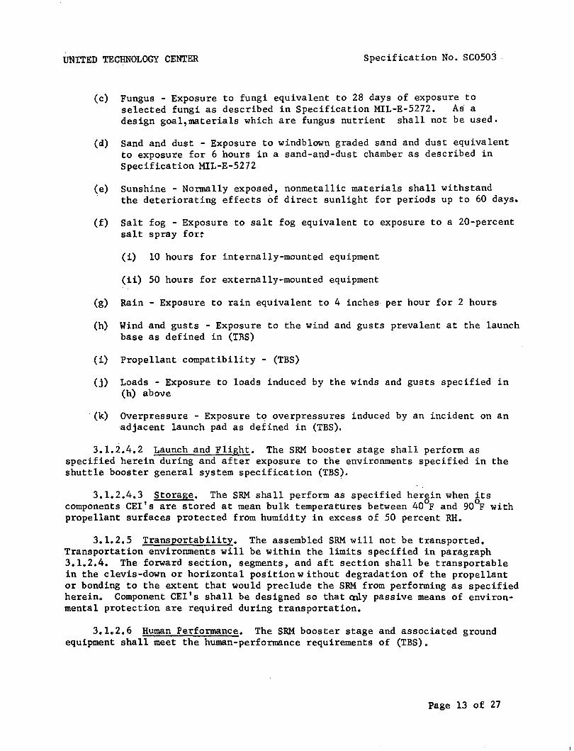
UNITED TECHNOLOGY CENTER Specification No. SC0503
(c)
(d)
(f)
Fungus - Exposure to fungi equivalent to 28 days of exposure toselected fungi as described in Specification MlL-E-5272. Asadesign goa1,materia1s which are fungus nutrient- shall not be used.
Sand and dust - Exposure to windblown graded sand and dust equivalentto exposure for 6 hours in a sand-and-dust chamber as described inSpecification MlL-E-5272
Sunshine - Normally exposed, nonmetallic materials shall withstandthe deteriorating effects 6f direct sunlight for periods up to 60 days.
Salt fog - Exposure to salt fog equivalent to exposure to a 20-percentsalt spray for~
(i) 10 hours for internally-mounted equipment
(ii) 50 hours for externally-mounted equipment
(g) Rain - Exposure to rain equivalent to 4 inches per hour for 2 hours
(h) Wind and gusts - Exposure to the wind and gusts prevalent at the launchbase as defined in (IRS)
(i) Propellant compatibility - (TBS)
(j) Loads - Exposure to loads induced by the winds and gusts specified in(h) above
- (k) Overpressure - Exposure to overpressures induced by an incident on an-adjacent launch pad as defined in (TBS).
3.1.2.4.2 Launch and Flight. The SRM booster stage shall perform asspecified herein during and after exposure to the environments specified in theshuttle booster general system specification (TBS).
3.1.2.4.3 Storage. The SRM shall perform as specified herein when itscomponents CElIs are stored at mean bulk temperatures between 400F and 900F withpropellant surfaces protected from humidity in excess of 50 percent RH.
3.1.2.5 Transportability. The assembled SRM will not be transported.Transportation environments will be within the limits specified in paragraph3.1.2.4. The forward section, segments, and aft section shall be transportablein the clevis-down or horizontal position without degradation of the propellantor bonding to the extent that would preclude the SRM from performing as specifiedherein. Component CElIs shall be designed so that ally passive means of environmental protection are required during transportation.
3.1.2.6 Human Performance. The SRM booster stage and associated groundequipment shall meet the human-performance requirements of (TBS).
Page 13 of 27

UNITED TECHNOLOGY CENTER
3.1.2.7 Safety.
Specification No. SC0503
3.1.2.7.1 Flight Safety - Design of airborne systems shall meet therequirements of applicable range safety specifications (TBS).
3.1.2.7.2 Ground Safety. The SRM shall be compatible with the shuttlebooster general specification (TBS).
3.1.2.7.3 Nuclear Safety. Not applicable.
3.1.2.7.4 Personnel Safety. Provisions for personnel safety shall bein accordance with the shuttle booster general specification (TBS).
3.1.2.7.5 Explosive and/or Ordnance Safety. The system shall comply withthe requirements of paragraph 3.1.2.7.4 of this CEI Specification and the shuttlebooster general specification (TBS) to the extent specified in the componentCEI Specifications. The explosive classification of each assembled SRM shallbe Class 2in accordance with AFM-127-100.
3.2 Configuration Item Definition.
3.2.1 Interface Requirements.
3.2.1.1 Schematic Arrangement. Each SRM shall conform to the dimensionsshown in UTC Drawing C09008. The schematic arrangement of the overall systemand each electrical system shall be as shown in Figures 26 through 30 and UTCDrawing (TBS).
Page 14 of 27

UNITED TECHNOLOGY CENTER
3.2.1.2 Detailed Interface Definition.
Specification No. SC0503
3.2.1.2.1 System Interfaces. All interfaces between the SRM boosterstage, the orbiter vehicle, and the facility will be defined and controlledby the following interface documents:
(TBS)
3.2.1.2.2 AGE Interfaces. Necessary interfaces for the SRM booster stagelaunch pad testing shall be provided for mating with the following equipment: .
(TBS)
3.2.2 Component Definition.
3.2.2.1 Customer-Furnished Property List. The following items, which areto be furnished by the customer, are required for flight CEI operation:
(a) Component configuration items (see 3.3.1.3)
3.Z.2.2 Engineering-Critica1-Components List. Engineering criticalcomponents are listed in the componentconftguration item specifications.
3.2.2.3 Logistics Critical Components List. Logistics critical componentsare listed in the component configuration item specifications.
3.3 Design and Construction.
3.3.1 General Design Features.
3.3.1.1 General Design and Construction Requirements. The SRM designshall comply with the shuttle booster general system specification (TBS).
3.3.1.2 Description.
3.3.1.2.1 Solid Rocket Booster Stage. The solid rocket booster stageshall consist of four solid rocket motors, their attach structure and thevarious systems required by this specification. Each motor shall be a 7 segmentl20-inch diameter motor with spherical end closures at each end. The segmentsand closures are joined with a pressure sealing clevis joint. An aerodynamicnose fairing attaches to the forward end and houses portions of the electricalsystem and the forward staging rocket motors.
Page 15 of 27

UNITED TECHNOLOGY CENTER Specification No. SC0503
3.3.1.2.2 Segments and Closures. Each segment is insulated with rubberand cast with composite, aluminized propellant in the form of a hollow cylinder.One end of the grain is restricted from b~rning by a rubber restrictor and atapering of the central perforation provides the required tai10ff thrust characteristics. The forward closure is insulated with rubber and propellant is castin the form of an eight-point star with ports provided to allow for thrusttermination. The aft closure is rubber insulated and has a circular port grainconfiguration.
3.3.1.2.3 Nozzle and Exit Cone. To the aft closure is attached a 52-inchdiameter ablative throat and a 200 conical ablative exit cone with an expansionratio of 10·6:1.
3.3.1.2.4 Thrust Vector Control System. Thrust vector control is providedby movable nozzles on each SRM. Each nozzle is supported by a constant volumefluid filled bearing which transmits the nozzle b10woff loads and thrust vectoring loads to the SRM by means of two annular rolling convolutes. Movement ofthe nozzle, within the limits of the fluid bearing, is produced by actuatorsplaced in mutually perpendicular planes. Hydraulic power for the actuators isprovided by a regulated pressure supply system using a solid propellant gasgeneration as the energy source. Actuator position control is accomplishedby an electronic control unit which resolves and conditions vehicle guidancesystem steering commands into the appropriate control responses.
3.3.1.2.5 Attach Structure. The four solid rocket motors are attachedto the orbiter tank by a thrust transmission structure near the forward end ofthe SRM which transmits SRM thrust to the orbiter, and by an aft structureWhich reacts the transverse and radial loads. The aft structure also providesground support for a single SRM during buildup and ground support for theassembled vehicle. Provisions for mounting staging motors are provided at thefore and aft ends of each SRM.
3.3.1.2.6 Emetg~ncy Detection System. Detection of impending solidrocket motor failures necessitating a mission abort is provided by this system.The output of various pairs of redundant transqucers are compared to predeterminedcriteria to determine presence of an impending failure situation. Parallelredundancy is utilized in this system to reduce the possibility of an inadvertentmission abort.
3.3.1.2.7 Instrumentation System. The instrumentation system shall monitorpertinent booster stage parameters and supply conditioned signals to the orbitertelemetry system to verify and evaluate booster stage status and performanceprior to and during flight. The system also provides signal inputs and outputsvia the ground umbilical cable required to accomplish verification tests on thebooster stage. The design of the instrumentation system shall be such that nosingle instrumentation system component failure will result in performancedegradation of any other booster stage system such that the limits of thisspecification are exceeded.
Page 16 of 27

UNITED TECHNOLOGY CENTER Specification No. SC0503·
3.3.1.2.8 Ordnance System. The ordnance systems for the SRM booster stageprovides the capability of performing the functions of booster ignition,' staging,thrust termination, and inadvertent separation detection by initiation of ordnancedevices. The ordnance electrical system provides the power and control of thefiring units to initiate the devices. Firing unit charging is accomplished uponcommand from the orb1ter vehicle 01( jround station. .
3.3.1.2.9 Redundancy. Redundancy shall be utilized, to the maximum ex~ent
practicable, in all systems to exclude the possibility of a single non-structuralfailure causing out-of-specification performance.
3.3.1.2.10 Weights. The predicted component weights are given in Table III.
Table III.
Component
Attach structureForwardAft
Separation system
-Solid motor (empty)Case
Forward ClosureSegments (Total)Aft ClosureAssembly Hardware
Insulation. Forward Closure
Segments (Total)Aft" Closure
IgnitorThrust TerminationNozzle
MovableFixed
Actuation System
Component Weights
Weight
(12,342)5,5166,826
1,238
(73,938)(49,252)
5,92838,780
4,196348
(12,230)1,7109,3451,175
3781,556
(10,522)8,2582,264
930
Electrical and Instrumentation
Weight Empty
Solid Propellant
Single Loaded Motor - Total
Interstage Structure
STAGE TOTAL
1,123
89,571
591 ,800
681,371
1,000
Page 17 of 27

UNITED TECHNOLOGY 'cENTER Specification No. SC0503
3.3.1.3 Component Configuration Items. The following subparagraphs identifythe component configuration items which form each SRM of the booster stage.
3.3.1.3.1 Forward Section, Rocket Motor. Each rocket motor forward ~ection
shall be in accordance with UTC Specification (TBS).I
3.3.1.3.2 Aft Section, Rocket Motor. The rocket motor aft section shallbe in accordance with UTC Specification (TBS).
3.3.1.3.3 Segment Assembly, Rocket Motor. The rocket motor segmentassembly shall be in accordance with UTC Specification (TBS).
3.3.1.3.4 Nose Section, Rocket Motor. The rocket motor nose section shallbe in accordance with UTC Specification (TBS).
3.3.1.3.5 Extension. Nozzle Exit Cone. The nozzle exit cone extensionshall be in aC90rdance with UTC Specification (TBS).
3.3.1.3.6 Battery Set. All flight batteries shall be in accordance withUTC Specification (TBS).
3.3.1.3.7 Ordnance Set, Rocket Motor. The rocket motor ordnance set shallbe in accordance with UTC Specification (TBS).
3.3.1.3.8 Mechanical Hardware Set, Rocket Motor. The .rocket motor mechanicalhardware set shall be in accordance with UTC Specification (TBS).
3.3.1.3.9 Aft Structure, Rocket Motor. The rocket motor aft structureshall be in accordance with UTC Specification (TBS).
3.3.1.3.10 Flight Instrumentation Set, Rocket Motor. The rocket motorflight instrumentation set shall be in accordance with UTC Specification (TBS).
3.3.2 Selection of Specifications and Standards. The selection of specifications and standards shall be in accordance with shuttle booster generalspecification (TBS).
3.3.3 Materials, Parts, and Processes. Materials, parts and processesused in each SRM shall conform to the applicable requirement as specified in'shuttle booster general specification (TBS) as further defined by componentCEI Specifications referenced in paragraph 3.3.1.
3.3.4 Standard and Commercial Parts. Standard and commercial parts shallbe in accordance with shuttle booster general system specification (TBS).
3.3.5 Moisture and Fungus Resistance. Materials used in this CEI shallcomply with the requirements of shuttle booster general system specification(TBS) as specified in the component CEI Specifications.
Page 18 of 27

.UNITED TECHNOLOGY CENTER Specification No. SC0503
303.6 corrosion of Metal Parts. All metal parts used in fabrication ofthe SRM shall be corrosign resistant or suitably treated to resist corrosionwhen exposed to the environmental conditions specified in paragraph 3.1.2.4.Wherever practical, the use of dissimilar metals, as defined in StandardMS33586, in contact with each other shall be· avoided.
3.3.7 Interchangeability and Rep1aceabi1ity. The interchangeability andrep1aceabi1ity, as specified in MIL-STD-447, of the SRM components shall bein accordance with MIL-I-8500.
3.3.8 Workmanship. Each SRM shall be fabricated and finished in such amanner that criteria of appearance, fit, and adherence to specified tolerancesshall be observed. Particular attention shall be given to the neatness andthoroughness of soldering, wiring, marking of parts and assemblies, plating,painting, riveting, machine-screw assemblage, welding and brazing, and freedomof parts from burrs and sharp edges.
303.9 Electromagnetic Interference. ~h SRM shall meet the electromagnetic interference requirements of Electromagnetic Compatibility ControlPlan (TBS)o
3.3.10 Identification and Marking. E&h SRM shall be identified and markedin accordance with MIL-STD-130 and (TBS).
3.3.11 Storage. Eoch assembled SRM and its components shall conform to thestorage requirements of paragraphs 3.1.2.3 and 3.1.204, as applicable.
3.3.12 Cleanliness. Each SRM and its components shall meet the cleanlinessrequirements of (TBS).
4. QUALITY ASSURANCE PROVISIONS.
4 01 Category I Test. Category I tests as used herein shall be definedas contractor-performed component, subsystem and full-scale static sea level tests.Records arid documentation of results of all Category I testing.sha1i be maintained in comprehensive, legible format.
4.1.1 Engineering Test and Evaluation. Engineering tests and evaluationsshall be conducted to provide maximum assurance of successful completion of thequalification and category II system tests specified below.
Page 19 of 27

UNITED TECHNOLOGY CENTER Specification No. Sq0503
4.1.1.1 Development Testing. (TBS) motor firing tests shall be conducted at a UTC test facility during the development phase, (TBS) verticalat UTC and (TBS) horizontal thrust termination test. Motors shall be instrumented during these firings to evaluate the internal ballistic performance,TVC performance, and electrical system performance. Test configuration shallbe as spectfied in (TBS).
4.1.2 Preliminarv Qualification Tests. (TBS) rocket motors identicalin configuration to the final flight configuration will be fired in a preliminary flight rating test (PFRT) program to be conducted at a UTC testfacility. The differences in configuration will be limited to those requiredfor the inverted-from-flight attitude firings and are defined in (TBS).Successful completion of these firings will constitute the preliminary qualification test program.
4.1.3 Formal Qualification Tests. The following subparagraphs specifythe requirements for, and methods of, formally verifying that each requirement in Section 3 has been satisfied.
4.1.3.1 Inspection. The following requirements of Section 3 shall beverified by an inspection at a time and place to be determined mutually bythe customer and UTC: (TBS)
4.1.3.2 Analysis. Conformance to the following requirements shall beverified by comparative analysis of engineering documentation developed underprevious programs and during the testing of 4.1.1.1 and 4.1.2. No furthertesting will be conducted to verify conformance to these requirements. (TBS)
4.1.3.3 Demonstrations. Not applicable.
4.1.3.4 Tests. The following requirements in Section 3 shall be verifiedduring the preliminary qualification tests of 4.1.2: (TBS)
4.1.4 Reliability Tests and Analysis. At the start of the acquisitionphase a reliability mathematical model shall be presented to justify reliabilityfailure allocations for the various CEI components. The results of tests,failure reports, and conclusions as to system reliability shall be presented tothe customer throughout the acquisition program. No special testing shall bespecifically conducted to satisfy the provisions of 3.1.2.1.
4.1.5 Engineering Critical Component Qualification. Not applicable.
4.1.6. Interface Testing.
4.1.6.1 System Interfaces. Conformance to the requirement of paragraph3.2.1. 2.1 "System Interface" shall be verified by comparative analysis ofengineering documentation developed under previous programs and during selectedtesting according to 4.1.1.1 and 4.1.2 as follows:
Page 20 of 27

UNITED TECHNOLOGY CENTER Specification No. SG0503
4.1.6.1.1 Para~etric Interfaces. SRM seal-level ballistic and TVC performanc~ as specified in (TBS) shall be verified to the extent analyzed by 4.1.3.2and 4.1.3.4.
4.1.6.1.2 Structural and DYnamic Load Interfaces. These interfaces asspecified in (TBS) , shall be verified only to the extent that mass propertyrequirements shall be verified as appropriate according to 4.1.3.2.
4.1.6.1.3 Electrical Interfaces. These interfaces as specified in (TBS)shall be tested as defined by (TBS). (ref: 4.1.6.1.4)
4.1.6.1.4 Testing Interfaces. These interfaces, as specified in (TBS)shall be verified to the extent where UTC electrical test requirements areapplicable to the testing of 4.1.1.1 and 4.1.2. (reference 4.1.6.1.8 forfluid systems verifications.)
4.1. 6.1. 5 Physical Interfaces. Dimensional requirements only, as specifiedin (TBS), shall be verified according to the inspections of 4.1.3.1.
4.1.6.1.6 Electrical Interfaces.· These interfaces, as specified in (TBS),shall be verified by testing as defined by (TBS). (ref.: 4.1.6.1.4)
4.1.6.1.7 Envelope Interface. Dimensional requirements only, as specifiedin (TBS), shall be verified according to the inspections of 4.1.3.1.
4.1.6.1.8 Fluid Interfaces. To the extent that the fluid interfaces arerequired for the testing of 4.1.1.1 and 4.1.2, the interfaces (mechanical,fluid quantity and fluid quality) used for static test will be consistent withthe requirements of (TBS) and thereby verify adequacy of requirements.
4.1.6.1.9 Installation Interfaces. Dimensional requirements only, asspecified in (TBS), shall be verified according to the inspections of 4.1.3.1.
4.2 Category II Test Program. The requirements of 3.3.9 shall be verifiedby tests to be performed after the SRM stage has been integrated' into an assembledlaunch vehicle. The solid rocket motors shall demonstrate the following minimumvehicle centerline vacuum web action time total impulse when assembled andlaunched as a Stage of the space shuttle launch vehicle in accordance withMIL-STD-471: (TBS)
5. PREPARATION FOR DELIVERY. (TBS)
6. NOTES.
6.1 Supplemental Information. Maximum use shall be made of componentsqualified under other programs.
6.1.1 Definitions. For purposes of this specification the followingdefinitions shall apply:
Page 21 of 27
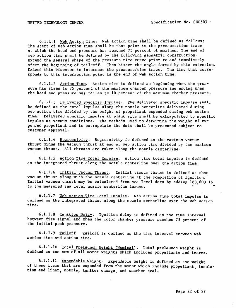
UNITED TECHNOLOGY CENTER Specification No. SC0503
6.1.1.1 Web Action Time. Web action time shall be defined as follows:The start of web action time shall be that point in the pressure/time traceat which the head end pressure has reached 75 percent of maximum. The end ofweb action time shall be defined by the following geometric construction.Extend the general shape of the pressure time curve prior to and immediatelyafter the beginning of tail-off. Then bisect the angle formed by this extension.Extend this bisector to intersect the pressure/time trace. The time that corresponds to this intersection point is the end of web action time.
6.1.1.2 Action Time. Action time is defined as beginning when the pressure has risen to 75 percent of the maximum chamber pressure and ending whenthe head end pressure has fallen to 10 percent of the maximum chamber pressure.
6.1.1.3 Delivered Specific Impulse. The delivered specific impulse shallbe defined as the total impulse along the nozzle centerline delivered duringweb action time divided by the weight of propellant expended during web actiontime. Delivered specific impulse at plant site shall be extrapolated to specificimpulse at vacuum conditions. The methods used to determine the weight of expended propellant and to extrapolate the data shall be presented subject tocustomer approval.
6.1.1.4 Regressivity. Regressivity is defined as the maximum vacuumthrust minus the vacuum thrust at end of web action time divided by the maximumvacuum thrust. All thrusts are taken along the noz~le centerline.
6.1.1.5 Action Time Total Impulse. Action time total impulse is definedas the integrated thrust along the nozzle centerline over the action time.
6.1.1.6 Initial Vacuum Thrust. Initial vacuum thrust is defined as thatvacuum thrust along with the nozzle centerline at the completion of ignition.Initial vacuum thrust may be calculated from sea level data by adding l83,60~ lb
fto the measured sea level nozzle centerline thrust.
6.1.1.7 Web Action Time Total Impulse. Web action time total impulse isdefined as the integrated thrust along the nozzle centerline over the web actiontime.
6.1.1.8 Ignition Delay. Ignition delay is defined as the time intervalbetween fire signal and when the motor chamber pressure reaches 75 percent ofthe initial peak pressure.
6.1.1.9 Tailoff. Tailoff is defined as the time interval between webaction time and action time.
6.1.1.10 Total Prelaunch Weight (Nominal). Total prelaunch weight isdefined as the sum of all motor weights which includes propellants and inerts.
6.1.1.11 Expendable Weight. Expendable weight is defined as the weightof those items that are expended from the motor which include propellant, insulation and liner, nozzle, igniter charge, and weather seal.
Page 22 of 27

UNITED TECHNOLOGY CENTER Specification No. SG0503
6.1.1.12 Weight Empty. Weight empty is defined as the total of inertmotor component weights excluding R&D instrumentation.
6.1.1.13 Burnoutis burnout condition.minus inert expendableweight.
Motor Weight. Total prelaunch weight minus expendablesA definition of burnout weight is prelaunch weightweight excluding expended propellant and igniter charge
6.1.1.14 Loaded Propellant Weight. Loaded propellant weight is definedas all solid propellant weight in the rocket motor.
6.1.1.15 Nominal Inert Motor Weight. Nominal inert motor weight includesthe following: The motor case with nozzle, thrust termination port covers andstacks, skirts, igniter, and internal insulation. It does not include the TVCsystem and its attachments, instrumentation, ordnance system, power supplies.,other electrical systems, external insulation, all vehicle attachment and aerodynamic fairings.
6.1.1.16 Mass Fraction. The nominal propellant mass fraction (~p) isdetermined by the following method:
~p = W / (W + W.)P P ~
Where: W = Loaded Propellant Weightp
W. = Nominal Inert Motor Weight~
6.1.1.17 Resolution. Resolution is defined as the m~n~mum change in inputvoltage necessary to produce a change in generated side force, in the same direction as the previous change.
6.1.1.18 Hysteresis. Hysteresis is defined as the difference in inputvoltage required to produce a change in generated thrust vector moment arm(TVMA) when the direction of the TVMA is changed due to command voltage reversals.
6.1.1.19 Deflection Angle. Deflection angle is defined as the arctan ofthe side thrust measured perpendicular to the nozzle centerline divided by theaxial thrust measured along the nozzle centerline.
6.1.1.20 Launch Reaction Time. Launch reaction time is defined as thetime required to prepare to launch a vehicle following the completion of prelaunch checkout.
6.1.1.21 Abort Recycle Time. Abort recycle time is defined as the timerequired to launch a vehicle following an abortive launch attempt.
6.1.1.22 The SRM Pitch (Yaw) Thrust Vector Angle. The angle between theSRM motor centerline and the projection of the SRM thrust vector into theSRM pitch (yaw) plane.
Page 23 of 27

UNITED TECHNOLOGY CENTER Specification No. SC0503
6.1.1.23 SRM Pitch (Yaw) Plane. The plane defined by the SRM motorcenterline and a line which is normal to the SRM centerline and parallel tothe vehicle pitch (yaw) plane.
6.1.1.24 The SRM Pitch (Yaw) Thrust Vector Moment Arm. The length ofthe perpendicular line from the SRM motor centerline at missle station (TBS)to the SRM projection of the thrust vector into the pitch (yaw) plane.
6.1.1.25 Solid Rocket Motor Centerline. The line joining the centerof the aft closure-to-nozzle throat bolt circle to the center of the forwardclosure in the plane of the forward attach structure.
6.1.1.26 Nozzle Centerline. The line joining the center of the nozzlethroat to the center of the nozzle exit.
6.1.1.27 Stage Centerline. The line Jo~n~ng the center of the stage/orbiter assembly joint bolt circle and the center of the aft structure supportstructure.
6.1.1.28 SRM Thrust Vector. The force vector whose magnitude and variability is defined by paragraph 3.1.1.1.1, and whose direction and variabilityis defined by paragraph 3.1.1.1.2.
601.1.29 Stage Roll Plane. A plane perpendicular to the stage centerline.which intersects the stage centerline at missile station (TBS).
6.1.1.30 Stage Roll Control Moment. The resultant moment about the stagecenterline of the sum of the SRM thrust vectors projected into the stage rollplane.
Page 24 of 27

UNITED TECHNOLOGY CENTER
10. APPENDIX
Specification No. SC0503
10.1 Test Configuration. The static test configuration of the SRM shallconform to UTC drawing (TBS). This drawing shows sever.al obvious differencesfrom the flight configuration. These differences shall not affect ?erformancebut are related to ordance, structural, and instrumentation measurements whichpertain directly to the static test program.
Specific differences shall include the following areas: (TBS)
Page 25 of 27

UNITED TECHNOLOGY CENTER
The following figures are to be supplied:
Specification No. ·SC05Q3
Figure 1. Ignition Transient l56-Inch Thrust Versus Time & NozzleSea Level at 60°F
Figure 2. Ignition Transient l56-Inch Pressure Versus Time at 60°F
Figure 3. Vacuum Thrust Versus Time, 40°F
Figure 4. Vacuum Thrust Versus Time, 60°F
Figure 5. Vacuum Thrust Versus Time, 70°F
Figure 6. Vacuum Thrust Versus Time, 90°F
Figure 7. Sea Level Thrust Versus Time, 40°F
Figure 8. Sea Level Thrust Versus Time, 60°F
Figure 9. Sea Level Thrust Versus Time, 70°F
Figure 10. Sea Level Thrust Versus Time, 90°F
Figure 11. Forward Head Pressure Versus Time, 40°F
Figure 12. Forward Head Pressure Versus Time, 60°F
Figure 13. Forward Head Pressure Versus Time, 70°F
Figure 14. Forward Head Pressure Versus Time, 90°F
Figure 15. Aft End Pressure Versus Time, 40°F
Figure 16. Aft End Pressure Versus Time, 60°F
Figure 17. Aft End Pressure Versus Time, 70°F
Figure 18. Aft End Pressure Versus Time, 90°F
Figure 19. Aft to Forward Head Pressure Ratio Versus Time
Figure 20. Thrust Vector Angle Versus Command Voltage andChamber Pressure
Figure 21. Thrust Vector Moment Arm Versus Command Voltageam Nominal Chamber Pressure
Figure 22. Roll Control Moment Versus Roll Command Voltageand Nominal Chamber Pressure
Page 26 of 27

UNITED TECHNOLOGY CENTER Specification No. SC0503
Figure 23. Frequency Response
Figure 24. Slew Rates
Figure 25. Net Thrust Versus Time from Thrust Termination Actuation
Figures 26 through 30. Schematic Arrangements of SRM Electrical Systems
Page 27 of 27

UNITED TECHNOLOGY CENTER
(PRELIMINARY)
Specification No. SC0504
PRIME ITEM DEVELOPMENT SPECIFICATION
SOLID ROCKET MOTOR, SPACE SHUTTLE BOOSTER, S6-l20
Basic Approved by ___(United Technology Center)
Date. _
Basic Approved by _
Date....,..... ~ _
Page 1 of 29

UNITED TECHNOLOGY CENTER Specification No. SC0504
1. SCOPE. This specification establishes the performance, design,development, and test requirements for the S6-l20 space shuttle boosterstage prime item.
2. APPLICABLE DOCUMENTS. The following documents form a part of thisspecification to the extent specified herein. In the event of conflict betweendocuments referenced here and the contents of this specification, the contentsof this specification shall be considered a superseding requiremento
SPECIFICATIONS
Military
MIL-E-5272
MIL-H-6083
MIL-I-8500
United Technology Center
(TBS)
(TBS)
(TBS)
(TBS)
(TBS)
(TBS)
(TBS)
(TBS)
(TBS)
(TBS)
(TBS)
Environmental Testing, Aeronautical andAssociated Equipment, General Specification for
Hydraulic Fluid, Petroleum Base,Preservative
Interchangeability and Replaceabilityof Component Parts for Aircraft andMissiles
Forward Section, Rocket Motor
Mechanical Hardware Set, Rocket Motor
Ordnance Set, Rocket Motor
Segment Assembly, Rocket Motor
Aft Section, Rocket Motor
Extension, Nozzle Exit Cone
Nose Section, Rocket Motor
Aft Structure, Rocket Motor
Interstage Structure
Flight Instrumentation Set, Rocket Motor
Battery Set (31 July 1964)
Page 2 of 29

UNITED TECHNOLOGY CENTER
STANDARDS
Military
MIL-STD-130
MIL-STD-447
MIL-STD-470
MIL-STD-471
MIL-STD-778
MS33586
DRAWINGS
United Technology Center
C09006
(TBS)
OTHER PUBLICATIONS
AFM 127-100
(TBS)
(TBS)
(TBS)
(TBS)
(TBS)
(TBS)
Specification No. SC0504
Identification Marking of US MilitaryProperty
Definitions of Interchangeability,Substitute and Replacement Items
Maintainability Program Requirements(for Systems and Equipment)
Maintainability Demonstration Requirements
Maintainability Terms and Definitions
Metals, Definition of Dissimilar
Rocket Motor Assembly
Electrical System - Interconnect Diagram
Explosives Safety Manual
Range Safety Manual
Policies, Procedures, and Criteria
Facility Contract End Item and InterfaceSpecification, Performance, Design andInterface Requirements for Space ShuttleBooster
Interface Specification, Solid RocketMotor to Launch Vehicle System - ParametricInterfaces (Performance, Environmentaland Flight Control)
Interface Specification, Solid RocketBooster Stage Orbiter Vehicle System Structural and Dynamic Loading Interfaces
Interface Specification, Solid Rocket BoosterStage to Orbiter Vehicle System - ElectricalInterfaces
Page 3 of 29

UNITED TECHNOLOGY CENTER
(TBS)
(TBS)
(TBS)
(TBS)
. (TBS)
(TBS)
(TBS)
(TBS)
(TBS-NASA)
3. REQUIREMENTS
3.1 Performance.
Specification No. SC0504
Interface Specification, ,Solid RocketBooster Stage to Orbiter Vehicle System Testing Interfaces
Interface Control Drawing, Solid RocketBooster Stage to Orbiter Vehicle System Physical Interfaces (Mechanical ~ Structural)
Interface Control Drawing, Solid Rock~t
Booster Stage to Orbiert Vehicle Syste~ Elect~1cal Interfaces
Interface Control Drawing, Solid RocketBooste~ Stage to Orbiter Vehicle System Envelope Interfaces
Inte~f~ce Control Drawing, Solid RocketBooster St~ge to Orbiter Vehicle System Fluid Interfaces
Interface Control Drawing, Solid RocketBooster Stage to Launch ·Oroiter VehicleSystem
Electromagnetic Compatibility (EMC)Control Plan
System Effectiveness Management Plan
Space Shuttle Booster System Performance/Design Requirements, General Specification
3.1.1 Functional Characteristics. The solid Rocket Motor (SRM) booster stageshall conform to thefollowing functional ch~racteristics fran sea level to ~O'O,OOOfeet (when ignited in air at altitudes up to 2500 feet) for motor mean bulktemperatures of (TBS) degrees Fahrenheit (OF) to (TBS). The design temperaturefor all calculations and reporting shall be (TBS). Thrust vector characteristicsare specified relative to the motor centerline at missile station (TBS).
3.1.1.1 Primary Performance Characteristics.
3.1.1.1.1 Propulsion System Performance Characteristics.
Page 4 of 29
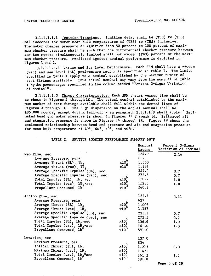
UNITED TECHNOLOGY CENTER Specification No. SC0504
3.1.1.1.1.1 Ignition Transient. Ignition delay shall be (TBS) tq.(TBS)milliseconds for motor mean bulk temperatures of (TBS) to (TBS) inclusive.The motor chamber pressure at ignition from 50 percent to 100 percent of maximum chamber pressure shall be such that the differential chamber pressure betweenany two motors simultaneously ignited shall not exceed (TBS) percent of the maximum chamber pressure. Predicted igniter nominal performance is depicted inFigures 1 and 2. .
3.1.1.1.1.2 Vacuum and Sea Level Performance. Each SRM shall have a vacuum(vac) and sea level (SL) performance rating as specified in Table I. The limitsspecified in Table I apply to a nominal established by the maximum number oftest firings available. This actual nominal may vary from the nominal of TableI by the percentages specified in the column headed "Percent 3-Sigma Variationof Nominal".
3.1.1.1.1.3 Th~ust Charac~eristics. Each SRM thrust versus time shall beas shown in Figures 3 through 10. The actual nominal established by the maximum number of test firings available shall fall within the dotted lines ofFigufes 3 through 10. The 3 er dispersion on the actual nominal shall be±95,000 pounds, except during tail-off when paragraph3.1.• 1.L9 sh:al~_app1.y•. Estimated head end motor pressure is shown in Figures 11 through 14. Estimated aftend stagnation pressure is shown in Figures 14 through 18. Figure 19 shows theestimated relationship between head end pressure and aft end stagnation pressurefor mean bulk temperature of 40°, 60°, 70°, and 90°F.
6xl06xlO
TABLE I. SHUTTLE BOOSTER PERFORMANCE SUMMARY 60°F
Nominal Percent 3-SigmaRating Variation of Nominal124.0 2.166521.0501.231232.4 0.7272.5 0.7130.2 1.0152.6 1.0560.2
Web Time, secAverage Pressure, psiaAverage Thrust (SL) , lbAverage Thrust (vac), ltfAverage Specific Impulse (SL), secAverage Specific Impulse (vac), secTotal Impulse (SL) , lb -secTotal Impulse (vac), ltf-secPropellant Consumed, lb
Action Time, secAverage Pressure, psiaAverage Thrust (SL) , lbAverage Thrust (vac) , lt
fAverage Specific Impulse (SL), secAverage Specific Impulse (vac), secTotal Impulse (SL), lb -secTotal Impulse (vac), ltf-secPropellant Consumed, lb
6xl06xlO
135.76271.0061.187231.1272.5136.6161.0591.0
3.11
0.70.71.01.0
Duration, secMaximum Pressure, psiInitial Thrust (SL), lb
fMaximum Thrust (vac), lOfTotal Impulse (vac), lbf-secPropellant Consumed, lb
137.08341.2131.431161.3591.8
6.0
1.0
Page 5 of 29
UNITED TECHNOLOGY CENTER Specification No. SC0504
3.1.1.1.1.4 Maximum Expected Operating Chamber Pressure. The maximumexpected operating chamber pressure (MEOP) shall be 1,000 pounds per squareinch gage (psig).
3.1.1.1.1.5 SRM Thrust Vector. Solid rocket motor thrust performance isdefined for a motor whose nozzle centerline is coincident with the motor centerline. Alignment and movement of the thrust vector is defined in 3.1.1.1.2.
3.1.1.1.1.6 Stage Thrust Vec'tor. Stage thrust vector performance isdefined for the thrust vector sum of the individual solid rocket motors. Thestage thrust vector location, altgnment and movement is defined in 3.1.1.1.2relative to the stage centerline and to the intersection of the stage centerline with the stage/orbiter separation plane, MS (TBS).
3.1.1.1.1. 7 Nozzle Characteristics. (TBS)
3.1.1.1.1. 8 Propellant. (TBS)
3.1.1.1.1. 9 Thrust Decay (TBS)3.1.1.1.2 Primary Thrust Vector Control <TVC) System Performance
Characteristics. The TVC system shall provide the performance indicated belowduring stage operation under initial prelaunch temperature of 25°F to 100°F.The TVC system shall utilize moveable nozzles on each SRM to provide omni-axial thrust vector orientation in accordance with pitch, yaw, and roll commandsignals from the vehicle guidance system. The TVC performance of the individualSRMs and combined stage shall be as specified in the TVC Math Model,specification (TBS).
3.1.1.1.2.1 TVC System Operation. The stage TVC system shall consist ofomni-directional moveable nozzles. Each SRM shall have a single moveable nozzleoperated by two servo-controlled hydraulic actuators located in mutually perpendicular planes. The actuators shall position the SRM nozzles in accordance withpitch, yaw, and roll commands from the vehicle guiciance system. Nozzle rotationshall be limited electronically to prevent overtravel in any axis. Controlaxes interactions and actuator cross coupling shall be defined.and compensationprovided as required to obtain vehicle response in accordance with commandcontrol moments within the control variation defined herein.
3.1.1.1.2.2 Booster Stage Axes Definition. Table II shows the stageaxes definition and indicates the command voltages and polarities required toprovide control moments about the roll, pitch, and yaw axes.
3.1.1.1.2.3 Stage Thrust Vectoring. The nominal stage pitch (yaw) thrustvector angle as a function of command voltage and nominal motor chamber pressureshall be as shown in Figure and described in the TVC Math Model, for allstage thrust vector angles between ±10 degrees.
3.1.1.1.2.4 Stage Thrust Vector Moment Arm. The nominal stage pitch(yaw) thrust vector moment arm as a function of command voltage and nominalmotor chamber pressure shall be as shown in Figure and as described in theTVC Math Model, for all thrust vector moment arms within ± (TBS) meters.
Page 6 of 29

UNITED TECHNOLOGY CENTER Specification No. SC0504
Table II. Axes Definition and Command Voltage,..---.-- _._ .._-----,
• +Pitch
__ • __+Yaw
cw~.~CCW~ ROll- ~
Booster SRM Axes Definition Looking Forward
Command Voltage Relativeto its individual correspondingreturn
Externally Directed Force
Pitch of same polarity ascommand
II
i!
Yaw of same polarity as Icommand I
-10 to +10 volts on roll Roll CW for (+) commands and Icommand lines (three redundant CCW for (-) commandspairs) l
---+-------
-10 to +10 volts on yawcommand lines (three redundantpairs)
-10 to +10 volts on pitchcommand lines (three redundantpairs)
3.1.1.1.2.3 SRM Thrust Vectoring. The nominal SRM pitch (yaw) thrustvector angle, as a function of command voltage and nominal motor chamber pressure,shall be as shown in Figure 20 and as described in the TVC Math. Model, for allSRM thrust vector angles between ±10 degrees.
3.1.1.1.2.4 SRM Thrust Vector Moment Arm. The nominal SRM pitch (yaw)thrust vector moment arm as a function of command voltage and nominal motorchamber pressure shall be as shown in Figure 21 and as described in the TVCMath. Model, for all thrust vector moment arms within ± (TBS)inches.
Page 7 of 27

UNITED TECHNOLOGY CENTER Specification No. SC0504
3.1.1.1.2.5 TVC Hysteresis. Three-sigma deviations from nominal TVCrelationships in 3.1.1.1.2.3 and 3.1.1.1.2.4 due to command voltage reversalsshall not exceed the greater of ±(TBS)% or ±(TBS) degrees, or the greater of±(TBS)% or ±(TBS) inches, respectively, from ignition to web action time; andshall not exceed the greater of ±(TBS)% or ±(TBS) degrees, or ±(TBS)% or ±(TBS)inches, respectively, from web action time to action time.
3.1.1.1.2.6 TVC Variability. Three-sigma variability of the stage thrustvector ~ngle shall not exceed the greater of ±(TBS)% or ±(TBS) degree, andvariability of the slope of the command voltage to thrust vector moment armrelationship shall not exceed the greater of ±(TBS)% or t(TBS) inches/volt fromignition to web action times; and shall not exceed ±(TBS) degrees, and thegreater of ±(TBS)% or ±(TBS) inches/volt, respectively, from web action time toaction time. This variability shall include all deviations, tolerances, andcross-coupling effects excepting variations in the nominal motor chamberpressure with stage mean bulk temperature.
3.1.1.1.2.7 Roll Control Moments. The nominal stage roll control momentas a function of roll command voltage and nominal motor chamber pressure shallbe as shown in Figure 22 and as described in the TVC Math Model. Three-sigmavariations shall not exceed the greater of ±(TBS)% or ±(TBS) Newton meters fromignition to web action time; or the greater of ±(TBS)% or ±(TBS) inch-poundsfrom web action time to action time. Three-sigma deviations from the nominalcommand voltage-to-roll control moment relationship due to command voltagereversal shall not exceed ±(TBS) inch-pounds from ignition to web action time;and ±(TBS) inch-pounds from web action time to action time.
3.1.1.1.2.8 Resolution. The TVC system resolution within the range offlO degrees of SRM thrust vector angle shall not exceed (TBS) volts from ignitionto web action time and (TBS) volts from web action time to action time.
3.1.1.1.2.9 Frequency Response. The total thrust vector control systemfrequency response at any ambient voltage command level in the defined nozzleaxes for motor chamber pressures between (TBS) and (TBS) psia shall be as specifiedby the upper and lower limits of the amplitude ratio and phase lag given inFigure 23. This curve is valid as long as the maximum command voltage does notexceed 10 VDC, the velocity or rate of change of the command vqltage is belowthe minimum slew rates specified in Figure 24, and the minimum command is greaterthan (TBS) VDC.
3.1.1.1.2.10 Slew Rate. The TVC system shall be capable of changing thevehicle thrust vector angle at a minimum slew rate of 5 degrees per secondthroughout motor operating time. This requirement shall apply for all motorand actuation system operating conditions in conjunction with external nozzleloads and environments as specified in (TBS). Slew rate is defined as theinstantaneous rate of change of thrust vector angle for command changesexceeding (TBS) volts at a rate exceeding (TBS) volts per second. The minimumand maximum slew rate limits as a function of flight time shall be as shownin Figure 24. Minimum slew rate is derived assuming nominal SRM performancecombined with minus 3-sigma control system performance and plus 3-sigma externalnozzle loads. Maximum slew rates is derived assuming nominal SRM performancecombin~d with plus 3-sigma control system performance and minus 3-sigmaexternal nozzle loads.
Page 8 of 29

UNITED TECHNOLOGY CENTER Specification No. SCOs02
3.1.1.1.3 SRM Ignition. Each stage of the booster stage shall pr~vide anintegral igniter motor that shall perform the function of initiating stageignition. Simultaneous ignition of each stage of the booster stage shall beaccomplished by receipt of simultaneous command signals, from the orbiteror fro~ ground equipment, to the ordnance electrical system of each stage.
3.1.1.1.4 Staging Performance. (TBS) staging motors per stage, (TBS)in the nose section and (TBS) in the aft section, shall supply the lateralstaging impulse to each SRM to fulfill the requirements of the shuttle boostergeneral system specification (TBS). Staging ignition initiation shall beaccomplished by the stage ordnance electrical system upon receipt of commandfrom the orbiter.
3.1.1.1.5 Flight Safety. To preclude or limit hazard to personnel and/orequipment, each SRM of the booster stage shall incorporate:l)a thrust termination system with provisions for activation when commanded by the orbiter vehicleor upon detection of an inadvertent separation of an SRM from the launch vehicle,and, 2) an inadvertent separation detection system (ISDS), and 3) an emergencydetection system for monitoring critical booster parameters and providing signalsto the orbiter crew. The design of these sys.tems shall be in accordance withthe requirements of Range Safety Manual (TBS) , Shuttle Booster General SystemSpecification (TBS) and Component eEl Specifications.
3.1.1.1.5.1 Thrust Termination Performance. A two-port thrust terminationsystem shall be provided on each solid rocket motor. The thrust terminationsystem shall effectively neutralize the axial thrust of each SRM by venting thecombustion chamber at the forward end of each SRM. Each solid rocket motorand its thrust termination system shall be capable of surviving the environments created by thrust termination for a period of (TBS) seconds after theinitiation of thrust termination. The thrust termination performance for asingle solid rocket motor is shown in Figure 25.
3.1.1.1.5.2 Emergency Detection System. The emergency detectionsystem shall provide the folloWing output signals to the orbiter.
(a). Fast Failure: A signal shall be present when an emergencycondition exists which will result in motor failure with (TBD) secondsand an immediate abort is required.
(b) Slow Failure: A signal shall be present when an emergencycondition exists which will result in motor failure after at least(TBD) seconds from initial detection.
(c) Unverified Failure: A signal shall be present when anemergency condition is sensed by only one of a pair of redundant transducers.
Page 9 of 29

UNITED TECHNOLOGY CENTER Specification No. SC0504
(d) Emergency Detection System Self Check: a 'signal shall bepresent when all Malfunction Detection System self check Circuits areindicating proper operation.
An emergency detection system input shall be p!ovided such that thesystem can be disabled on command from the orbiter.
3.1.1.1.5.3 Inadvertent Separation Detection System (ISDS). Each SRMof the booster stage shall provide an ISDS that shall detect the inadvertentloss of electrical cabling between the orbiter/launch vehicle and automaticallyinitiate thrust termination prior to receipt of a disable command from theorbiter. The ISDS shall be an integral part of the booster ordnan~e electricalsystem.
3.1.1.1.6 Electrical Power, Control, and Distribution. Each SRM of thebooster stage shall provide the airborne power, switching capability fromground power to airborne power, and the distribution of all airborne power tothe TVC system, ordnance system, emergency detection system and flight instru-. ,mentation system. The electrical systems of the booster stage shall receive anddistribute ground power for SRM systems ground operation and checkout. Allsystems shall operate from 28 VDC (nominal) power sources.
3.1.1.2 Secondary Performance Characteristics.
3.1.1.2.1 Instrumentation System Performance Characteristics. The boosterstage instrumentation system shall provide signal outputs to the orbiter for thepurpose of verification and evaluation of booster stage status and performanceprior to and during flight. The functional status of specified redundancyfeatures included in the other booster stage systems shall be indicated by discrete output signals to the orbiter.
3.1.1.2.2 Checkout Provisions. Provisions shall be made to allow thefollowing booster stage verification tests to be performed on an assembledlaunch vehicle via the airborne and ground electrical interfaces.
(a) Detailed functional tests, asspecified in(TBSh of all electricaland mechanical subsystems including operational status of redundant features.
(b) System operability (quick look) tests, as specified in(TBS)of theflight critical active systems,providing go/no go signals, including checksof redundant features.
(c) Integrated-system test, as specified in(TBS~ performed as asimulated countdown and flight with the complete launch system.
(d) Booster stage component malfunction isolation and componentcheckout tests as specified in(TBS}
Page 10 of 29
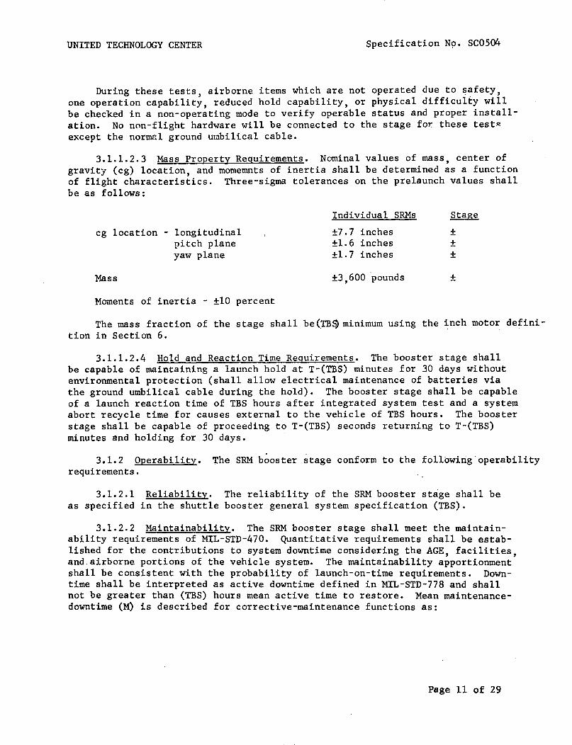
UNITED TECHNOLOGY CENTER Specification No. SC0504
During these tests, airborne items which are not operated due to ~afety,
one operation capability, reduced hold capability, or physical difficulty willbe checked in a non-operating mode to verify operable status and proper installation. No non-flight hardware will be connected to the stage for these test~
except the norIllc~l ground umbilical cable.
3.1.1.2.3 Mass Property Requirements. Nominal values of mass, center ofgravity (cg) location, and momemnts of inertia shall be determined as a functionof flight characteristics. Three-sigma tolerances on the prelaunch values shallbe as follows:
cg location - longitudinalpitch planeyaw plane
Mass
Moments of inertia - ±10 percent
Individual SRMs
±7.7 inches±1.6 inches±l. 7 inches
±3,600 pounds
Stage
±±±
±
The mass fraction of the stage shall be(~B$ minimum using the inch motor definition in Section 6.
3.1.1.2.4 Hold and Reaction Time Requirements. The booster stage shallbe capable of maintaining a launch hold at T-(TBS) minutes for 30 days withoutenvironmental protection (shall allow electrical maintenance of batteries viathe ground umbilical cable during the hold). The booster stage shall be capableof a launch reaction time of TBS hours after integrated system test and a systemabort recycle time for causes external to the vehicle of TBS hours. The boosterstage shall be capable of proceeding to T-(TBS) seconds returning to T-(TBS)minutes and holding for 30 days.
3.1.2 Operability. The SRM booster stage conform to the following·operabilityrequirements.
3.1.2.1 Reliability. The reliability of the SRM booster stage shall beas specified in the shuttle booster general system specification (TBS).
3.1.2.2 Maintainability. The SRM booster stage shall meet the maintainability requirements of MIL-STD-470. Quantitative requirements shall be established for the contributions to system downtime considering the AGE, facilities,and airborne portions of the vehicle system. The maintainability apportionmentshall be consistent with the probability of launch-on-time requirements. Downtime shall be interpreted as active downtime defined in MIL-STD-778 and shallnot be greater than (TBS) hours mean active time to restore. Mean maintenancedowntime (M) is described for corrective-maintenance functions as:
Page 11 of 29

UNITED TECHNOLOGY CENTER
Where:
Nc
Specification No. SCOS04
M = M hoursct
mean maintenance correction-time for sub-system(arithmetic mean)
Nc= number of corrective maintenance-functions for
modular remove/replace maintenance concept
= active maintenance correction-time per correctivemaintenance task
The quantitative M allocations shall be as follows:
(TBS)
The M allocations do not apply on a lower level of assembly because maintenance or test results pertinent to a requirement for maintenance only occursat the fully assembled level. The above subsystems are defined in the UTCSystem Effectiveness Plan, (TBS).
3.1.2.2.1 Maintenance and Repair Cycles. Maintainability analyses shallestablish time goals for the completion of maintenance activities and the associated design and procedural approaches. This data will be incorporated intoequipment specifications and, thus, constitute objectives to be accomplishedduring the design process. Maintenance functions for support of the SRM arecorrective-maintenance functions. Preventive maintenance is not considered inthe maintenance concept.
3.1.2.2.2 Service and Access. Access shall be provided so all interfaceconnections and maintenance operations can be performed. The ordnance andTVC subsystems shall be capable of checkout and servicing while installed inthe <booster stage SRM. Access requirements shall be evaluated to ascertain <performance of corrective-maintenance tasks upon which active maintenancedowntime is based, and which are organizational level remove/replace maintanance functions.
Page 12 of 29
UNITED TECHNOLOGY CENTER Specification No~ SC0504
3.1.2.3 Useful Life. The SRM booster stage shall comply with shuttlebooster general system specification (TBS). The SRM booster stage sha1l'meetthe requirements of this specification after exposure to the environmentspeci.f~ed in 3.~.2.4 for a period of one year. Cyclic life 1imit~tions shallbe as defined in the component CEI specifications (see 3.3.1.3).
3.1.2.4 Environmental.
3.1.2.4.1 Prelaunch. The SRM booster stage shall perform as specifiedherein after exposure to the following environments.
(a) Temperature - Surrounding air temperatures between 25° and100°F with mean bulk propellant temperatures of 40° to 90°F for periodsup to 60 days.
(b) Humidity - Relative humidities of up to 100 percent includingcondensation in the form of water or frost for periods up to 60 days.
(c) Fungus - Exposure to fungi equivalent to 28 days of exposureto selected fungi as described in Specification MIL-E-5272. As a designgoal materials which are fungus nutrients shall not be used. .
(d) Sand and dust - Exposure to windblown graded sand and dust equivalent to exposure for 6 hours in a sand-and-dust chamber as described inSpecification MIL-E-5272.
(e) Sunshine - Normally exposed, non-metallic materials shallwithstand the deteriorating effects of direct sunlight for periods up to60 days.
(f) Salt fog - Exposure to salt fog equivalent to exposure to a20-percent salt spray for:
(i) 10 hours for internally-mounted equipment
(ii) 50 hours for externally-mounted equipment
(g) Rain - Exposure to rain equivalent to 4 inches per hour for2 hours.
(h) Wind and gusts - Exposure to the wind and gusts prevalent atthe launch base as defined in (TBS).
(i) Propellant compatibility - (TBS)
(j) Loads - Exposure to loads induced by the winds and gusts specified in (h) above.
(k) Overpressure - Exposure to overpressures induced by an incidenton an adjacent launch pad as defined in (TBS).
Page 13 of 29

UNITED TECHNOLOGY CENTER Specification SC0504
3.1.2.4.2 Launch and Flight. The SRM booster stage shall perform asspecified herein during and after exposure to the environment specified inthe shuttle b~oster general system spcification (TBS).
3.1.2.4.3 Storage. The SRM booster stage shall perform as specifiedherein when its components CEls are stored at mean bulk temperatures between40°F and 90°F with propellant surfaces protected from humidity in excess of50 percent RH.
3.1.2.5 Transportability. The assembled SRM booster stage will not betransported. Transportation environments will be within the limits specifiedin 3.1.2.4. The forward section, segments, and aft section shall be transportable in the clevis-down or horizontal position without degradation of thepropellant or bonding to the extent that would preclude the booster stagefrom performing as specified herein. Component CEls shall be designed sothat only passive means of environmental protection are required during transportation.
3.1.2.6 Human Performance. The SRM booster stage and associated groundequipment shall meet the human-performance requirements of (TBS).
3.1.2.7 Safety.
3.1.2.7.1 Flight Safety. Design of airborne systems shall meet therequirements of applicable Range Safety Specification (TBS).
3.1.2.7.2 Ground Safety. The SRM shall be compatible with the shuttlebooster general specification (TBS).
Page 14 of 29

UNITED TECHNOLOGY CENTER
3.1.2.7.3 Nuclear Safety. Not applicable.
Specification No. SC0504
3.1.2.7.4 Personnel Safety. Provisions for personnel safety shall bein a~cordance with the shu~tle booster general specification (TBS).
3.1.2.7.5 Explosive and/or Ordnance Safety. The system shall comply wifuthe requirements of paragraph 3.1.2.7.4 of this CEI Specification and the shuttlebooster general specification (TBS) to the extent specified in the component CEISpecifications. The explosive classification of each assembled SRM of thebooster stage shall be Class 2 in accordance with AFM-127-l00.
3.2 CEI Definition.
3.2.1 Interface Requirements.
3.2.1.1 Schematic Arrangement. The SRM booster stage shall conform tothe dimensions shown in UTC Drawing C09006. The schematic arrangement ot theoverall system and each electrical system shall be as shown in Figures 26through 30 and UTe Drawing (TBS).
3.2.1.2 Detailed Interface Definition.
3.2.1.2.1 System Interfaces. All interfaces between the SRM booster stageand the orbiter vehicle and facility will be defined and controlled by the following interface documents:
(TBS)
3.2.1.2.2 AGE Interfaces. Necessary interfaces for the SRM booster stagelaunch pad testing shall De provided for mating with the following equipment:
(TBS)
3.2.2 Component Definition.
3.2.2.1 Customer-Furnished-Property List. The following items, whichare to be furnished by the customer, are required for flight CEI operation:
(a) Component CEls (see 3.3.1.3) of each SRM
3.2.2.2 Engineering-Critical-Components List. Engineering criticalcomponents are listed in the component CEI specifications.
3.2.2.3 Logistics Critical Components List. Logistics critical componentsare listed in the component CEI specifications.
3.3 Design and Construction.
3.3.1 General Design Features.
3.3.1.1 General Design and Construction Requirements. The SRM designshall comply with the shuttle booster general system specification (TBS).
Page 15 of 29

UNITED TECHNOLOGY CENTER
3.3.1.2 Description.
Specification No. SC0504
3.3.1.2.1 Solid Rocket Booster Stage. The solid rocket booster stageshall consist of six solid rocket motors attached together by their attachstructure, and the various systems required by this specification. Each motorshall be a (TBS)-segment l20-inch diameter motor with spherical end closures ateach end. The segments and closures are joined with a pressure sealing clevisjoint. The attach structure also serves to collect the thrust and steeringloads from each of the solid rocket motors and applies them to the orbiter atthe interstage structure.
3.3.1.2.2 Segments and Closures. Each segment is insulated with rubberand cast with composite, aluminized propellant in the form of a hollow cylinder.One end of the grain is restricted from burning by a rubber restrictor and atapering of the central perforation provides the required tailoff thrust characteristics. The forward closure is insulated with rubber and propellant is castin the form of an eight-point star with ports provided to allow for thrusttermination. The aft closure is rubber insulated and has a circular port grainconfiguration.
3.3.1.2.3 Nozzle and Exit Cone. To the aft closure is attached a 50-inchdiameter ablative throat and a 20°-conical ablative exit cone with an expansionratio of 12.7:1.
3.3.1.2.4 Thrust Vector Control System. Thrust vector control is providedby moveable nozzles on each SRM. Each nozzle is supported by a constant-volumefluid-filled bearing which transmits the nozzle blowoff loads and thrust vectoring loads to the SRM by means of two annular rolling convolutes. Movement ofthe nozzle, within the limits of the fluid bearing, is provided by actuatorsplaced in mutually perpendicular planes. Hydraulic power for the actuators isprovided by a regulated pressure supply system using a solid propellant gasgenerator as the energy source. Actuator position control is accomplished byan electronic control unit, which resolves and conditions vehicle guidancesystem steering commands into the appropriate control responses.
3.3.1.2.5 Attach Structure. The attach structure consists of a thrusttransmission structure and an aft skirt for each SRM. The aft skirt providesground support during buildup of a single SRM and ground support for theassembled launch vehicle. The thrust transmission structure transmits theSRM thrust to the interstage structure described in UTC Specification (TBS).Provisions for mounting staging motors are provided in the thrust transmissionstructure and in the aft skirts. The interstage structure interfaces withthe orbiter stage and includes the system required to separate the boosterstage after SRM burnout.
Page 16 of 29

UNITED TECHNOLOGY CENTER Specification No. SC0504
3.3.1.2.6 Emergency Detection System. Detection of impending S~
booster failures necessitating a mission abort is provided by this system.The output of various pairs of redundant transducers are compared to predetermined criteria to de~erm~ presence of an impending failure pituation.Parallel redundancy is utilized in this system to reduce the possibility ofoccurrence of an inadvertent mission abort.
I
3.2.1.2.7 Instrumentation System. The instrumentation system shallmonitor pertinent booster stage parameters and supply conditioned signalsto the orbiter telemetry system to verify and evaluate booster stage statusand performance prior to and during flight. The system also provides signalinput and output via the ground umbilical cable, required to accomplishverification tests on the booster stage. The design of the instrumentationsystem component failure will result. in performance degradation of any otherbooster stage system such that the limits of this specification are exceeded.
Page 17 of 29
UNITED TECHNOLOGY CENTER Specification No. SC0504
3.3.1.2.8 Ordnance System. -The ordnance systems for the SRM boosterstage provided the capability of performing the functions of booster ignition,staging, thr~st terrninatirn, and inadvertent separation detection hy initiation of ord~ance devices. Th~ ordnance electrical system provides the powerand control of the firing units. Firing unit charging and triggering isaccomplished upon command from the orbiter vehicle or ground station.
3.3.1.2.9 Interstage Structure. The interstage structure shall transmitand distribute axial force, shear, and bending movement between the individualSRMs of the booster stage to the hydrogen-oxygen tank and shall provide sufficient separation between the SRM stage and the orbiter vehicle to allow SRMthrust termination port covers to clear the orbiter if the thrust terminationsystem is activated. The interstage structure shall provide an equipment bayfor housing some electrical components of the TVC, ordnance, emergency detectionand flight instrumentation systems. Provisions for compartment environmentalcontrol shall be made as necessary.
3.3.1.2.10 Redundancy. Redundancy shall be utilized, to the maximum extentpracticable, in all systems to exclude the possibility of a single non-structural failure causing out-of-specification performance.
3.3.1.2.11 Weight. The predicted component weights are given in table III.
3.3.1.3 Component CEls. The follOWing sub-paragraphs identify thecomponent CEls which form each SRM of the booster stage.
3.3.1.3.1 Forward Section, Rocket Motor. Each booster forwardsection shall be in accordance with UTC Specification (TBS).
3.3.1.3.2 Aft Section, Rocket Motor. The booster aft sectionshall be in accordance with UTC Specification (TBS).
3.3.1.3.3 Segment Assembly, Rocket Motor. The booster segmentassembly shall be in accordance with UTC Specification (TBS).,'
3.3.1.3.4 Nose Section, Rocket Motor. The booster nose sectionshall be in accordance with UTC Specification (TBS).
3.3.1.3.5 Extension, Nozzle Exit Cone. The nozzle exit cone extensionshall be in accordance with UTC Specification (TBS).
3.3.1.3.6 Battery Set. All flight batteries shall be in accordance withUTC Specification (TBS).
3.3.1.3.7 Ordnance Set, Rocket Motor. The booster ordnance setshall be in accordance with UTC Specification (TBS).
3.3.1.3.8 Mechanical Hardware Set, Rocket Motor. The boostermechanical hardware set shall be in accordance with UTC Specification (TBS).
3.3.1.3.9 Aft Structure, Rocket Motor. The booster aft sectionshall be in accordance with UTC Specification (TBS).
Page 18 of 29

UNITED TECHNOLOGY CENTER Specification No. SC0504
TABLE III. COMPONENT WEIGHTS
Component
Attach StructureForwardAft
Separation System
Solid Motor (Empty)Case
Forward ClosureSegments (Total)Aft ClosureAssembly Hardware
InsulationForward ClosureSegments (Total)Aft Closure
IgniterThrust TerminationNozzle
MoveableFixed
Actuation System
Electrical & Instrumentation
Weight Empty
Solid Propellant
Single Loaded Motor - Total
Interstage StructureStage Elect •. & Inst.
STAGE TOTAL
(8,942)2,1166,826
(73,938)(49,252)
5,92838,7804,196
348(12,230)
1,7109,3451,175
3781,556
(10,522)8,2522,264
930
634
84,444
591,800
676,244
32,800855
4,091,119
Page 19 of 29

UNITED TECHNOLOGY CENTER Specification No. Sc0504
3.3.1.3.10 Flight Instrumentation Set, Rocket Motor. The rocket motorflight instrumentation set shall be in accordance with UTC Specification (TBS).
3.3.1.3.11 Interstage Structure. The rocket motor booster interstage structureshall be in accordance with lITC Specification (TBS).
3.3.2 Selection of Specifications and Standards. The selection ofspecifications and standards shall be in accordance with shuttle booster generalsystem specification (TBS).
3.3.3 Materials, Parts, and Processes. Materials, parts and processesused in eoch SRM shall conform to the applicable requirements as specified inshuttle booster general system specification (TBS) as further defined by component CEI Specifications referenced in paragraph 3.3.1.
3.3.4 Standard and Commercial Parts. Standard and commercial parts shallbe in accordance with shuttle booster general system specification (TBS).
3.3.5 Moisture and Fungus Resistance. Materials used in this CEI shallcomply with the requirements of the shuttle booster general specification (TBS).
3.3.6 Corrosion of Metal Parts. All metal parts used in fabricationof the SRM shall be corrosion resistant or suitably treated to resist corrosionwhen exposed to the environmental conditions specified in 3.1.2.4. Whereverpractical, the use of dissimilar metals, as defined in Standard MS33586, incontact with each other shall be avoided.
3.3.7 Interchangeability and Replaceability. The interchangeability andreplaceability, as specified in MIL-STD-447, of the SRM components shall be· inaccordance with MIL-I-8500.
3.3~8 Workmanship. The SRM shall be fabricated and finished in such amanner that criteria of appearnce, fit, and adherence to specified tolerancesshall be observed. Particular attention shall be given to the neatness andthoroughness of soldering, wiring, marking of parts and assemblies, plating,painting, riveting, machine-screw assemblage, welding and brazing, and freedomof parts from burrs and sharp edges.
3.3.9 Electromagnetic Interference. The SRM shall meet the electromagnetic interference requirements of Electromagnetic Compatibility ControlPlan (TBS).
3.3.10 Identification and Marking. The SRM shall be identified andmarked in accordance with MIL-STD-130 and (TBS).
~.3.ll Stotag~. Th~ ass~mbl~d SkM booster stag~ a~d its eompo~~~ts shallconform to the storage requirements of 3.1.2.3 and 3.1.2.4, as applicable.
3.3.12 Cleanliness. The SRM booster stage and its components shallmeet the cleanliness requirements (TBS).
Page 20 of 29
UNITED TECHNOLOGY CENTER Specification No. SC0504
4. QUALITY ASSURANCE PROVISIONS.I
4.1 Category I Test. Category I tests as used herein shall be definedas cor.tracto:':' uerformed cor;lpor:.ent, subsystem and fulJ. scale static ~ €'7eltests. Records and documentation of results of all Category I testing shallbe maintained in comprehensive, legible format.
4.1.1 Engineering Test and Evaluation. Engineering tests and evaluations shall be conducted to provide maximum assurance of successful completion of the qualification and category II system tests specified below.
Page 21 of 29

UNITED tECHNOLOGY CENTER Specification No. SC0504
4.1.1.1 Development Testing. (TBS) motor firing tests shall be conducted at a UTC test facility during the development phase, (TBS) verticalat UTC and (TBS) horizontal thrust termination test. Motors shall be instrumented during ~hese firings to evaluate the internal ballistic performance,TVC performance, and electrical system performance. Test configuration s[.3l1be as specified in (TBS).
4.1.2 Preliminary Qualification Tests. (TBS) rocket motors identicalin configuration to the final flight configuration will be fired in a preliminary flight rating test (PFRT) program to be conducted at a UTC testfacility. The differences in configuration will be limited to those requiredfor the inverted-from-f1ight attitude firings and are defined in (TBS).Successful completion of these firings will constitute the preliminary qualification test program.
4.1.3 Formal Qualification Tests. The following subparagraphs specifythe requirements for, and methods of, formally verifying that each requirement in Section 3 has been satisfied.
4.1.3.1 Inspection. The following requirements of Section 3 shall beverified by an inspection at a time and place to be determined mutually bythe customer and UTC: (TBS)
4.1.3.2 Analysis. Conformance to the following requirements shall beverified by comparative analysis of engineering documentation developed underprevious programs and during the testing of 4.1.1.1 and 4.1.2. No furthertesting will be conducted to verify conformance to these requirements. (TBS)
4.1.3.3 Demonstrations. Not applicable.
4.1.3.4 Tests. The following requirements in Section 3 shall be verifiedduring the preliminary qualification tests of 4.1.2: (TBS)
4.1.4 Reliability Tests and Analysis. At the start of the acquisitionphase a reliability mathematical model shall be presented to jus-tHy reliabilityfailure allocations for the various CEI components. The results of tests ,failure reports, and conclusions as to system reliability shall be presented tothe customer throughout the acquisition program. No special testing shall bespecifically conducted to satisfy the provisions of 3.1.2.1.
4.1.5 Engineering Critical Component Qualification. Not applicable.
4.1.6. Interface Testing.
4.1.6.1 System Interfaces. Conformance to the requirement of paragraph3.2.1.2.1 "System Interface" shall be verified by comparative analysis ofengineering documentation developed under previous programs and during selectedtesting according to 4.1.1.1 and 4.1.2 as follows:
Page 22 of 2"9

UNITED TECHNOLOGY CENTER Specification No. SC0504
4.1.6.1.1 Parametric Interfaces. SRM seal-level ballistic and TVC performance as specified in (TBS) shall be verified to the extent analyzed by 4~1.3.2and 4.1.3.4.
4.1.6.1.2 ~tructura1 and Dynamic Load Interfaces. These interfaces &sspecified in (TBS) , shall be verified only to the extent that mass propertyrequirements shall be verified as appropriate according to 4.1.3.2.
4.1.6.1.3 Electrical Interfaces. These interfaces as specified in (TBS)shall be tested as defined by (TBS). (ref: 4.1.6.1.4)
4.1.6.1.4 Testing Interfaces. These interfaces, as specified in (TBS)shall be verified to the extent where UTC electrical test requirements areapplicable to the testing of 4.1.1.1 and 4.1.2. (reference 4.1.6.1.8 forfluid systems verifications.)
4.1.6.1.5 Physical Interfaces. Dimensional requirements only, as specifiedin (TBS), shall be verified according to the inspections of 4.1.3.1.
4.1.6.1.6 Electrical Interfaces.· These interfaces, as specified in (TBS),shall be verified by testing as defined by (TBS). (ref.: 4.1.6.1.4)
4.1.6.1.7 Envelope Interface. Dimensional requirements only, as specifiedin (TBS), shall be verified according to the inspections of 4.1.3.1.
4.1.6.1.8 Fluid Interfaces. To the extent that the fluid interfaces arerequired for the testing of 4.1.1.1 and 4.1.2, the interfaces (mechanical,fluid quantity and fluid quality) used for static test will be consistent withthe requirements of (TBS) and thereby verify adequacy of requirements.
4.1.6.1.9 Installation Interfaces. Dimensional requirements only, asspecified in (TBS), shall be verified according to the inspections of 4.1.3.1.
4.2 Category II Test Program. The requirements of 3.3.9 shall be verifiedby tests to be performed after the SRM stage has been integrated' into an assembledlaunch vehicle. The solid rocket motors shall demonstrate the following minimumvehicle centerline vacuum web action time total impulse when assembled andlaunched as a Stage of the space shuttle launch vehicle in accordance withMIL-STD-471: (TBS)
5. PREPARATION FOR DELIVERY. (TBS)
6. NOTES.
6.1 Supplemental Information. Maximum use shall be made of componentsqualified under other programs.
6.1.1 Definitions. For purposes of this specification the followingdefinitions shall apply:
Page 23 of 2~

UNITED TECHNOLOGY CENTER Specification No. SC0504
6.1.1.1 Web Action Time. Web action time shall be defined as follows:The start of web action time shall ,be,that point in the pressure/time trace
I I 'at which the head end pressure has reached 75 percent of maximum. The end ofweb action time shall be defined by the following geomp.tric construction.Extend'the geL1~ral shape of the pressur:= time curve prio:.': to and immedia::'~ly
after the beginning of tail-off. Then bisect the angle formed by this extension.Extend this bisector to intersect the pressure/time trace. The time that corresponds to this intersection point is the end of web action time.
6.1.1.2 Action Time. Action time is defined as beginning when the pressure has risen to 75 percent of the maximum chamber pressure and ending when
Ithe head end pressure has fallen tq 10 percent of the maximum chamber pressure.
6.1.1.3 Delivered Specific Impulse. The delivered specific impulse shallbe defined as the total impulse along the nozzle centerline delivered duringweb action time divided by the weight of propellant expended during web actiontime. Delivered specific impulse at plant site shall be extrapolated to specificimpulse at vacuum conditions. The methods used to determine the weight of expended propellant and to extrapolate the data shall be presented subject tocustomer approval.
6.1.1.4 Regressivity. Regressivity is defined as the maximum vacuumthrust minus the vacuum thrust at end of web action time divided by the maximumvacuum thrust. All thrusts are taken along the noz~le centerline.
6.1.1.5 Action Time Total Impulse. Action time total impulse is definedas the integrated thrust along the nozzle centerline over the action time.
6.1.1.6 Initial Vacuum Thrust. Initial vacuum thrust is defined as thatvacuum thrust along with the nozzle centerline at the completion of ignition.Initial vacuum thrust may be calcul~ted from sea level data by adding 183,603 lb
fto the measured sea level nozzle centerline thrust.
6.1.1.7 Web Action Time Total Impulse. Web action time total impulse isdefined as the integrated thrust along the nozzle centerline over the web actiontime.
6.1.1.8 Ignition Delay. Ignition delay is defined as the time intervalbetween fire signal and when the motor chamber pressure reaches 75 percent ofthe initial peak pressure.
6.1.1.9 Tailoff. Tailoff is defined as the time interval between webaction time and action time.
6.1.1.10 Total Prelaunch Weight (Nominal). Total prelaunch weight isdefined as the sum of all motor weights which includes propellants and inerts.
6.1.1.11 Expendable Weight. Expendable weight is defined as the weightof those items that are expended from the motor which include propellant, insulation and liner, nozzle, igniter charge, and weather seal.
Page 24 of 29
UNITED TECHNOLOGY CENTER Specification No. SC0504
6.1.1.12 Weight Empty. Weight empty is defined as the total of inertmotor component weights excluding R&D instrumentation.
6.1.1.13 ~urnout Motor Weight. Total prelaunch Tieight minus expendablesis burnout condition. A definition of ~urnout weigtt is prelauncn weLghtminus ine~t expendable weight excluding expended propellant and igniter chargeweight 0
601.1.14 Loaded Propellant Weight. Loaded propellant weight is definedas all solid propellant weight in the'rocket motor.
I
6.1.1.15 Nominal Inert Motor Weight. Nominal inert motor weight includesthe following: The motor case with nozzle, thrust termination port covers andstacks
tskirts, igniter, and internal insulation. It does not include the TVC
system and its attachments, instrumen~ation, ordnance system, power supplies.,other electrical systems, external insulation, all vehicle attachment and aero-·dynamic fairings.
6.1.1.16 Mass Fraction. The nominal propellant mass fraction (~p) isdetermined by the following method:
~p = W /p(W + W.)
P ~
inputdirec-
= Loaded IPropellant WeightWhere: WP
W. = Nominal Inert Motor Weight~ I
6.1.1.17 Resolution. Resolu~iO~ is defined as the m~n~mum change involtage necessary to produce a change in generated side force, in the sametion as the previous change.
6.1.1.18 Hysteresis. Hysteresis is defined as the difference in inputvoltage required to produce a change in generated thrust vector moment arm(TVMA) when the direction of the TVMA is changed due to command voltage reversals.
!6.1.1.19 Deflection Angle. :Deflection angle is defined as the arctan of
the side thrust measured perpendicular to the nozzle centerline divided by theaxial thrust measured along the nozzle centerline.
6.1.1.20 Launch Reaction Time. Launch reaction time is defined as thetime required to prepare to launch a vehicle following the completion of prelaunch checkout.
6.1.1.21 Abort Recycle Time. Abort recycle time is defined as the timerequired to launch a vehicle following an abortive launch attempt.
6.1.1.22 The SRM Pitch (Yaw) Thrust Vector Angle. The angle between theSRM motor centerline and the projection of the SRM thrust vector into theSRM pitch (yaw) plane.
Page 25 of 29
UNITED TECHNOLOGY CENTER Specification No. SC0504
6.1.1.23 SRM Pitch (Yaw) Plane. The plane defined by the SRM motorcenterline and a line which is normal to the SRM centerline and parallel' tothe vehicle pitch (yaw) plane.
6.1.1.24 The SRM Pitch (Yaw) Thrust Vector Mon,ent Arm. The lengtr ~f
the perpendicular line from the SRM motor centerline at missle station (7BS)to the SRM projection of the thrust vector into the pitch (yaw) plane.
6.1.1.25 Solid Rocket Motor Centerline. The line joining the centerof the aft closure-to-nozzle throat bolt circle to the center of the forwardclosure in the plane of the forward attach structure.
6.1.1.26 Nozzle Centerline. The line joining the center of the nozzlethroat to the center of the nozzle exit.
6.1.1.27 Stage Centerline. The line Jo~n~ng the center of the stage/orbiter assembly joint bolt circle a~d the center of the aft structure supportstructure.
6.1.1.28 SRM Thrust Vector. The force vector whose magnitude and variability is defined by paragraph 3.1.1.1.1, and whose direction and variabilityis defined by paragraph 3.1.1.1.2.
601.1.29 Stage Roll Plane. A plane perpendicular to the stage centerline,which intersects the stage centerline at missile station (TBS).
6.1.1.30 Stage Roll Control Moment. The resultant moment about the stagecenterline of the sum of the SRM thrust vectors projected into the stage rollplane.
Page 26 of 29
UNITED TECHNOLOGY CENTER
10. APPENDIX
Specification No. SC0504
10.1 Test Configuration. The static test configuration of the SRM shallconform t~ l~r. drawing (TB8). This drewing shows seve~a1 obvioue p~~&erpncef
from the flight configuration. These differences shall not affect ?erfurmancebut are related to ordance, structural, and instrumentation measurements whichpertain directly to the static test program.
Specific differences shall include the following areas: (TBS)
Page 27 of 29
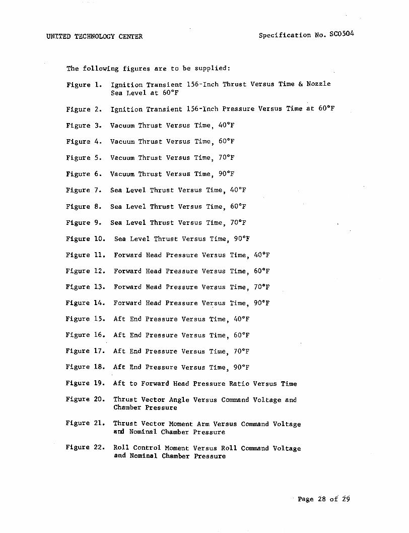
UNITED TECHNOLOGY CENTER
The following figures are to be supplied:
Specification No. SC0504
Figure 1. Ignition Transient l56-Inch Thrust Versus Time & NozzleSea Level at 60°F
Figure 2. Ignition Transient l56-Inch Pressure Versus Time at 60°F
Figure 3. Vacuum Thrust Versus Time, 40°F
Figure 4. Vacuum Thrust Versus Time, 60°F
Figure 5. Vacuum Thrust Versus Time, 70°F
Figure 6. Vacuum Thrust Versus Time, 90°F
Figure 7. Sea Level Thrust Versus Time, 40°F
Figure 8. Sea Level Thrust Versus Time, 60°F
Figure 9. Sea Level Thrust Versus Time, 70°F
Figure 10. Sea Level Thrust Versus Time, 90°F
Figure 11. Forward Head Pressure Versus Time, 40°F
Figure 12. Forward Head Pressure Versus Time, 60°F
Figure 13. Forward Head Pressure Versus Time, 70°F
Figure 14. Forward Head Pressure Versus Time, 90°F
Figure 15. Aft End Pressure Versus Time, 40°F
Figure 16. Aft End Pressure Versus Time, 60°F
Figure 17. Aft End Pressure Versus Time, 70°F
Figure 18. Aft End Pressure Versus Time, 90°F
Figure 19. Aft to Forward Head Pressure Ratio Versus Time
Figure 20. Thrust Vector Angle Versus Command Voltage andChamber Pressure
Figure 21. Thrust Vector Moment Arm Versus Command Voltageand Nominal Chamber Pressure
Figure 22. Roll Control Moment Versus Roll Command Voltageand Nominal Chamber Pressure
Page 28 of 29
UNITED TECHNOLOGY CENTER Specification No. SC0504
Figure 23. Frequency Response
Figure 24. Slew Rates
Figure 25. Net Thrust Versus Time from Thrust Termination Actuation
Figures 26 through 30. Schematic Arrangements of SRM Electrical Sy~tems
Page 29 of 29