solarcore tm - australia · solarcore tm solar hot water systems ... cylinder empty (kg) 88 95...
TRANSCRIPT
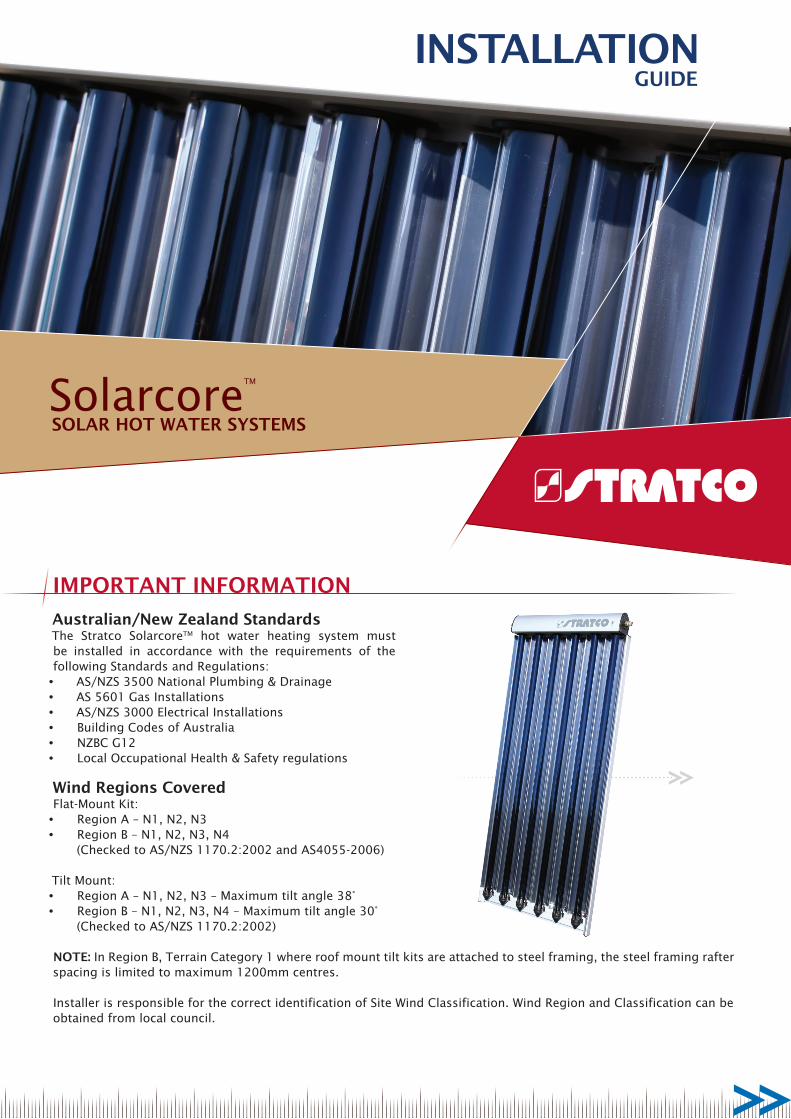
INSTALLATIONGUIDE
SolarcoreTM
SOLAR HOT WATER SYSTEMS
IMPORTANT INFORMATION
Australian/New Zealand StandardsThe Stratco SolarcoreTM hot water heating system must be installed in accordance with the requirements of the following Standards and Regulations:• AS/NZS 3500 National Plumbing & Drainage• AS 5601 Gas Installations• AS/NZS 3000 Electrical Installations• Building Codes of Australia• NZBC G12• Local Occupational Health & Safety regulations
Wind Regions CoveredFlat-Mount Kit:• Region A – N1, N2, N3• Region B – N1, N2, N3, N4
(Checked to AS/NZS 1170.2:2002 and AS4055-2006)
Tilt Mount:• Region A – N1, N2, N3 – Maximum tilt angle 38°• Region B – N1, N2, N3, N4 – Maximum tilt angle 30°
(Checked to AS/NZS 1170.2:2002)
NOTE: In Region B, Terrain Category 1 where roof mount tilt kits are attached to steel framing, the steel framing rafter spacing is limited to maximum 1200mm centres.
Installer is responsible for the correct identification of Site Wind Classification. Wind Region and Classification can be obtained from local council.
Total dissolved solids < 600mg/litre or ppm
Total hardness < 200mg/litre or ppm
Chloride <250mg/litre or ppm
Sodium <150mg/litre or ppm
Magnesium <10mg/litre or ppm
Dissolved CO2 <18mg/litre or ppm
Saturation Index (Langelier) < +0.4 at 65°c
pH level 6.5 to 8.5
Table 1 - Water Quality Limits
present in swimming pool and spa water will result in corrosion and will void the warranty.
Freeze ProtectionThe solar collector is protected from damage during freezing weather conditions by automatically circulating water from the hot water storage tank.
If the solar collector temperature falls below 10°C, the circulation pump is activated periodically for brief intervals (indoor controller only). If the solar collector temperature falls below 5°C, the circulation pump is activated continuously.
The collectors have been tested and met the requirements of AS2712-2007 “Test for Protection against Freezing - Method B, Level 2”. The collectors lowest working temperature is -20°C.
It is critical that the automatic freeze protection function in the indoor controller is active by ensuring the freeze protection function “AF” is set to “1”. This is the default setting in the electronic controller. De-activating the freeze protection function “AF” by setting it to “0” is likely to result in damage to the solar collector during freezing weather conditions and will void the warranty.
Stagnation & OverheatingStagnation occurs when water stops flowing through the solar collector due to power failure, or when the circulation pump is switched off. This results in the solar collector temperature increasing during solar heating conditions, until the P&TR valve activates and releases hot water or steam from the system. This is normal and protects the storage tank from overheating.
The circulation pump is switched off automatically by the electronic controller if the water temperature exceeds 65°C in the hot water storage tank or 130°C in the solar collector. This also results in the solar collector temperature increasing until the P&TR valve activates and releases hot water or steam from the system. This is normal during extended periods of very hot, sunny weather or low hot water usage, and protects the solar hot water storage tank from overheating.
The circulation pump is switched on again when the water temperature falls below 80°C in the solar collector and below 65°C in the hot water storage tank.
During extended absences in summer it is advisable to cover the solar collector to avoid overheating the system and excessive dumping of hot water from the P&TR valve.
Hydrogen Gas Warning (For vitreous enamel hot water storage tanks with protective anode):If the hot water system is not used for two weeks or more, a quantity of highly flammable Hydrogen gas may accumulate in the hot water storage tank.
To dissipate this gas safely, it is recommended that a hot tap is turned on for several minutes or until discharge of gas ceases. Use a sink, basin or bath outlet but not a dish washer, clothes washer or other appliance.
Occupational Health & SafetySolar collectors are large, bulky items that are generally installed on the roof of a building. Installers must be adequately trained and aware of their responsibilities regarding manual handling and working at heights under local OH&S regulations.
The installer must take care to warn/protect the building occupants and public from personal injury which may result from:• Falling tools or materials.• Work site hazards.• Scalding from hot pipes and fittings or escaping hot
water or steam.
Qualified InstallersThe Stratco SolarcoreTM hot water system must be installed by licensed plumbing, gas fitting and electrical professionals that have been trained and authorised by Stratco.
Safety DevicesThe hot water system is fitted with the following safety devices to comply with regulations and ensure ongoing safe operation.• Pressure and temperature relief valve• Expansion control valve• Pressure limiting valve• Non-return valves• Tempering valve
It is important that these devices are maintained and tested/replaced at regular intervals by an Authorised Stratco installer, as outlined in the “Maintenance” section of these instructions. Drain lines from the pressure & temperature relief valve and expansion control valve should be kept free of blockages.
Water QualityThe water quality from metropolitan water supplies is generally suitable for the Stratco SolarcoreTM hot water heating system. The water quality from bore water supplies is generally not suitable for the hot water system.
The water quality must meet the limits shown in Table 1 “Water Quality Limits”. Water quality outside of these limits may cause early failure of the hot water system and will void the warranty. Please contact the relevant water supply authority or have the water tested if uncertain about the water supply quality.
CorrosionThe hot water system must not be used to heat a chlorinated swimming pool or spa water. The high levels of chloride

Solar Collectors
Electric Boosted Storage Tank
To Hot Water Outlets
Electric Element
Water Supply
Circulation Pump
Figure 1 - Split Solar Electric Boosted Hot Water System
Solar Collectors
Gas Boosted Storage Tank
Gas Booster
Water Supply
Gas Supply
To Hot Water Outlets
Circulation Pump
Figure 2 - Split Solar Gas Boosted Hot Water System
During this procedure there must be no smoking, open flame or electrical appliance operating nearby. If Hydrogen is discharged through the tap, it will probably make an unusual sound like air escaping.
Collector Weight & DimensionsThe solar collector evacuated tubes, header and associated pipe work do not contain large volumes of water and are able to be flush mounted on most roof structures and cladding materials due to their relatively low weight.
The weight, dimensions and capacity of the solar collectors, are given in Table 11 “Evacuated Tube Solar Collector Specifications”. It is the responsibility of the installer to ensure that the roof structure is able to withstand the static load applied by the solar collector/s.
The collector mounting system is not suitable for use in cyclonic regions.
PRINCIPLE OF OPERATIONThe Stratco SolarcoreTM hot water heating system collects heat energy from sunlight using an array of very efficient evacuated glass collector tubes. These are mounted on the roof and oriented towards the midday sun, where possible, to maximise the solar heating effect.
The evacuated glass collector tubes are so efficient that they can collect heat from sunlight during cool, windy or even overcast weather. The heat is rapidly transferred to water passing through copper pipes inside the evacuated glass tubes. A pump circulates the heated water to the hot water storage tank located at ground level.
An electronic controller with temperature sensors monitors the water temperature in the solar collector and hot water storage tank. The electronic controller turns the circulation pump on when the solar collector is 8°C hotter than the hot water storage tank and turns it off again when the temperature difference drops to 2°C. Solar heating continues until the water temperature in the hot water storage tank reaches a maximum of 65°C or there is insufficient heat available from the sun.
Additional heating is provided using a gas booster or electric boost element for periods when there is insufficient heat available from the sun.
Solar heating generally takes place between 9:00am and 3:00pm. Correct size and position of the solar collectors are important to ensure optimum performance of the solar hot water heating system. The solar collector should be capable of providing the majority of hot water needs on clear sunny days in summer, with boost heating only necessary during periods of high hot water consumption.
During periods of medium solar heating, such as overcast days, some boost heating will be required.
Under these conditions, the solar collector will preheat the water and reduce the amount of electricity or gas required to heat the water.
In heavily clouded weather when solar heating is not possible, the gas booster or electric boost element will provide all the heat necessary to ensure a continuous supply of hot water.

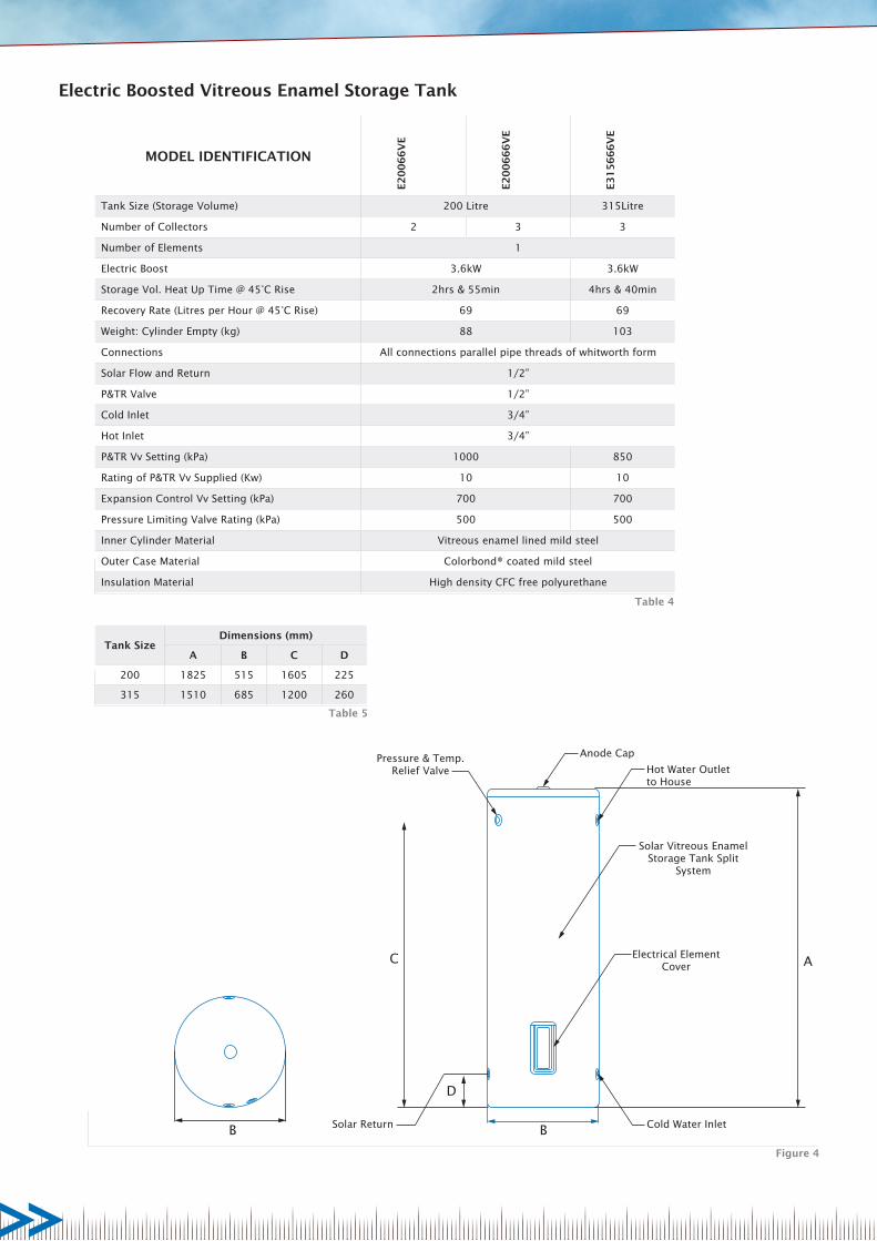
ELECTRIC BOOSTED VITREOUS ENAMEL TANK
200 or 315 litre
GAS BOOSTED VITREOUS ENAMEL TANK
215 or 270 litre
PRESSURE AND TEMPERATURE RELIEF(P&TR) VALVE 15mm
GAS BOOSTER
ELECTRONIC CONTROLLER
(Indoor)
ELECTRONIC CONTROLLER
(Outdoor)
SOLAR COLLECTOR TEMPERATURE SENSOR
(20m cable)
STORAGE TANK TEMPERATURE SENSOR
(10m cable- Indoor)(3m cable - Outdoor)
SOLAR COLLECTORQty: 2 or 3
BOTTOM STAINLESS STEEL STRAPS
Qty: 4 or 6
TOP STAINLESS STEEL STRAPS
Qty: 4 or 6
RETAINING PLATESQty: 4 or 6
1/4” CUP HEAD BOLTQty: 4 or 6
1/4” WASHERQty: 4 or 6
1/4” NYLOCK NUTQty: 4 or 6
ANGLE BRACE M10 NUTQty: n/a
M10 SOCKET BOLTQty: n/a
M10 WASHERQty: n/a
ANGLE BRACE(SHORT)
FRAME RAIL RAIL NUT TILT BRACKET CGI ROOF BRACKET FLAT ROOF BRACKET
TILT-MOUNT
CIRCULATION PUMP SOLAR NON-RETURN VALVE ASSEMBLY
CIRCULATION PUMP COVER
To ensure that the installation of the Stratco Solar Hot Water Heating System proceeds smoothly the installer should:• Confirm that all of the parts listed on the delivery documentation have been supplied.• Carefully read these instructions completely to ensure familiarity with all the steps involved.• Ensure that safety and regulatory requirements as outlined in the “Important Information” of these instructions are
followed throughout the installation procedure.
BEFORE YOU START

E
AC
D
BCold Water Inlet
Pressure & Temp. Relief
ValveSolar Return
Hot Water Outlet to House
Anode Cap
Solar Vitreous Enamel
Storage Tank Split System
Gas Booster
Tank SizeDimensions (mm)
A B C D E
215 1825 515 1605 225 709
270 1265 685 985 260 879
MODEL IDENTIFICATION
G2
15
20
N6
6V
E
G2
15
20
L6
6V
E
G2
15
26
N6
6V
E
G2
15
26
L6
6V
E
G2
15
20
N6
66
VE
G2
15
20
L6
66
VE
G2
15
26
N6
66
VE
G2
15
26
L6
66
VE
G2
70
20
N6
66
VE
G2
70
20
L6
66
VE
G2
70
26
N6
66
VE
G2
70
26
L6
66
VE
Tank Size (Storage Volume) 215 Litre 270 Litre
Number of Collectors 2 3 3
Continuous Flow Gas Boost Size L/min 20 26 20 26 20 26
Weight: Cylinder Empty (kg) 88 95
Connections All connections parallel pipe threads of whitworth form
Solar Flow and Return 1/2”
P&TR Valve 1/2”
Cold Inlet 3/4”
Hot Inlet 3/4”
P&TR Vv Setting (kPa) 1000 850
Rating of P&TR Vv Supplied (Kw) 10 10
Expansion Control Vv Setting (kPa) 700 700
Pressure Limiting Valve Rating (kPa) 500 500
Inner Cylinder Material Vitreous enamel lined mild steel
Outer Case Material Colorbond® coated mild steel
Insulation Material High density CFC free polyurethane
Figure 3
Table 3
Table 2
SPECIFICATIONS & DIMENSIONSGas Boosted Vitreous Enamel Storage Tank
B
AC
D
BSolar Return
Electrical Element Cover
Solar Vitreous Enamel Storage Tank Split
System
Anode CapPressure & Temp. Relief Valve Hot Water Outlet
to House
Cold Water Inlet
Tank SizeDimensions (mm)
A B C D
200 1825 515 1605 225
315 1510 685 1200 260
MODEL IDENTIFICATION
E2
00
66
VE
E2
00
66
6V
E
E3
15
66
6V
E
Tank Size (Storage Volume) 200 Litre 315Litre
Number of Collectors 2 3 3
Number of Elements 1
Electric Boost 3.6kW 3.6kW
Storage Vol. Heat Up Time @ 45°C Rise 2hrs & 55min 4hrs & 40min
Recovery Rate (Litres per Hour @ 45°C Rise) 69 69
Weight: Cylinder Empty (kg) 88 103
Connections All connections parallel pipe threads of whitworth form
Solar Flow and Return 1/2”
P&TR Valve 1/2”
Cold Inlet 3/4”
Hot Inlet 3/4”
P&TR Vv Setting (kPa) 1000 850
Rating of P&TR Vv Supplied (Kw) 10 10
Expansion Control Vv Setting (kPa) 700 700
Pressure Limiting Valve Rating (kPa) 500 500
Inner Cylinder Material Vitreous enamel lined mild steel
Outer Case Material Colorbond® coated mild steel
Insulation Material High density CFC free polyurethane
Figure 4
Table 5
Table 4
Electric Boosted Vitreous Enamel Storage Tank

Model Identification SWGB20N70D SWGB26N70D
Boost Capacity (L/min)
L/min @ 20°C Rise 20 26
L/min @ 25°C Rise 16 24
Max. Rated Flow (L/min) 20 26
Min. Supply Pressure for Maximum Rated Flow (kPa) 120 200
Min. Flow for Operation (L/min) 2.4 2.4
Frost Protection YES YES
Gas Consumption (max./min.) (Mj/hr) 125-18 188-23
Hot Water Delivery Temp. 70°C 70°C
Dimensions (HxWxD) (mm) 530 x 350 x 194 530 x 350 x 194
Weight (kg) 15 21
SWTC SWTCOD
Temp. (°C) Resistance (Ω) Resistance (Ω)
-20 922
-15 941
-10 961
-5 980
0 1000 27250
5 1019
10 1039
15 1058
20 1078
25 1097 10000
30 1117
35 1136
40 1155
45 1175
50 1194 4162
55 1213
60 1232
65 1252
70 1271
75 1290 1925
80 1309
85 1328
90 1347
95 1366
Controller Setting Designation Default Value
Switch-on Difference DO 8°C 8°C
Switch-off Difference DF 2°C 2°C
Storage max. Temperature SX 65°C 65°C
Switch-on Temp. Reheating TO 40°C (not used) N/A
Switch-off Temp. Reheating TF 40°C (not used) N/A
Freeze Protection Function
Collector AF
1 (freeze prot. function
active)
N/A
Operating Mode MM 4 (automatic) N/A
SWTC SWTCOD
Line Voltage 210-250V, 50-60Hz 85-264V, 50-60Hz
Power Consumption ca. 2VA 5VA max.
Protection Class IP 40 / DIN 40050 IP 54
Ambient Temperature 0-40°C 0-50°C
Contact Rating Solar Pump Output max. 4A 750W
Contact Rating Reheating Output max. 4A N/A
Total Switching Current max. 4A 750W
Fuse in the Controller Pot Fuse 4 AT N/A
Type of Sensors Pt1000, Ø6mm x 50mm Ø6mm x 30mm
Dimensions (HxWxD) (mm) 172 x 110 x 46 167 x 142 x 40
Model Identification UP 15 - 14B
Max. Operating Pressure 10 bar
Max. Operating Temperature 110°C
Min. Operating Temperature -25°C
Max. Head 7m
Nominal Operating Voltage 240V AC
Maximum Sound Pressure Level 43 dBa
Table 10
Table 8
Table 9
Table 7
Table 6
Circulation Pump Specifications
Electronic Controller Specification
Gas Boosters Specifications

Collector
Assembly
Dry Weight 19kg
Overall Dimension (LxWxD) (mm) 1640 x 700 x 100
Gross Collector Area 1.14m2
Aperture Area 1.0m2
Heat Transfer Fluid Water
Fluid Volume 0.8L
Connection Diameter 15mm
Max. Operating Pressure 10 bar
Max. Stagnation Temperature 295°C
Collector
Tubes
Tube Material Borosilicate 3.3 Glass
Tube Dimensions (ODxIDxTxL) (mm) 47 x 37 x 1.6 x 1500
Selective Absorber Material Aluminium Nitrite
Location
Collector Inclination for
optimum performance (+/-
20 degrees)
Adelaide 35°
Alice Springs 24°
Auckland 37°
Brisbane 27°
Broken Hill 31°
Cairns 17°
Canberra 35°
Christchurch 43°
Darwin 12°
Geraldton 28°
Hobart 42°
Mildura 34°
Melbourne 38°
Perth 32°
Port Hedland 20°
Rockhampton 24°
Sydney 34°
Townsville 19°
Wellington 41°
Table 12
Table 11
Horizontal ManifoldThe solar collector must be installed so the manifold runs horizontally across the roof.
Solar Collector OrientationThe solar collectors should be mounted on a North facing roof for Australia and New Zealand.
Plus or minus 45° of true North is acceptable. Mounting the solar collector on a North East or North West facing roof will only reduce solar collector efficiency by approximately 5%.
Solar Collector InclinationThe ideal inclination of the solar collectors is equal to the location’s latitude for optimum heat gain throughout the year. Table 12 gives latitudes of major cities in Australia and New Zealand.
Inclinations within plus or minus 20° of the location’s latitude are acceptable and will only reduce solar collector efficiency by approximately 5%.
Most standard roof pitches fall within this range and allow flush mounting of the solar collectors. Flush mounting is generally preferred from an aesthetic viewpoint.
A solar collector inclined at an angle steeper than the optimum angle will increase the heat gain during winter and decrease the heat gain during summer. This can be beneficial in locations where excessive heat is generated during summer.
Conversely, a solar collector inclined at an angle shallower than the optimum angle will increase the heat gain during summer and decrease the heat gain during winter.
SOLAR COLLECTOR POSITION & ORIENTATION
Evacuated Tube Solar Collector Specifications
Rafter
Tile Batten
Fixing strap - Secured with
two Hex head self-drilling
screws
Fixing strap - Secured with two Hex head self-drilling screws
Collector - Secured to strap with two screws
Collector - Secured to strap with retaining plates, screws and nuts
Figure 6
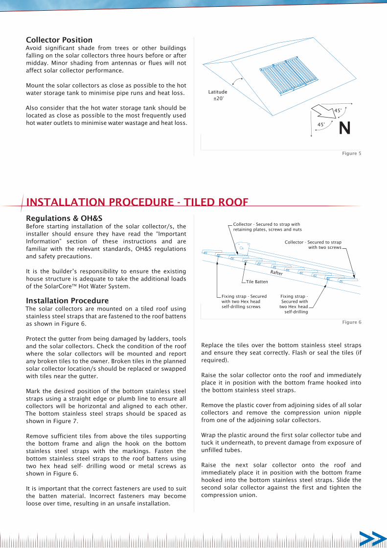
N45°
45°
Latitude ±20°
Figure 5
Regulations & OH&SBefore starting installation of the solar collector/s, the installer should ensure they have read the “Important Information” section of these instructions and are familiar with the relevant standards, OH&S regulations and safety precautions.
It is the builder’s responsibility to ensure the existing house structure is adequate to take the additional loads of the SolarCoreTM Hot Water System.
Installation ProcedureThe solar collectors are mounted on a tiled roof using stainless steel straps that are fastened to the roof battens as shown in Figure 6.
Protect the gutter from being damaged by ladders, tools and the solar collectors. Check the condition of the roof where the solar collectors will be mounted and report any broken tiles to the owner. Broken tiles in the planned solar collector location/s should be replaced or swapped with tiles near the gutter.
Mark the desired position of the bottom stainless steel straps using a straight edge or plumb line to ensure all collectors will be horizontal and aligned to each other. The bottom stainless steel straps should be spaced as shown in Figure 7.
Remove sufficient tiles from above the tiles supporting the bottom frame and align the hook on the bottom stainless steel straps with the markings. Fasten the bottom stainless steel straps to the roof battens using two hex head self- drilling wood or metal screws as shown in Figure 6.
It is important that the correct fasteners are used to suit the batten material. Incorrect fasteners may become loose over time, resulting in an unsafe installation.
INSTALLATION PROCEDURE - TILED ROOF
Collector PositionAvoid significant shade from trees or other buildings falling on the solar collectors three hours before or after midday. Minor shading from antennas or flues will not affect solar collector performance.
Mount the solar collectors as close as possible to the hot water storage tank to minimise pipe runs and heat loss.
Also consider that the hot water storage tank should be located as close as possible to the most frequently used hot water outlets to minimise water wastage and heat loss.
Replace the tiles over the bottom stainless steel straps and ensure they seat correctly. Flash or seal the tiles (if required).
Raise the solar collector onto the roof and immediately place it in position with the bottom frame hooked into the bottom stainless steel straps.
Remove the plastic cover from adjoining sides of all solar collectors and remove the compression union nipple from one of the adjoining solar collectors.
Wrap the plastic around the first solar collector tube and tuck it underneath, to prevent damage from exposure of unfilled tubes.
Raise the next solar collector onto the roof and immediately place it in position with the bottom frame hooked into the bottom stainless steel straps. Slide the second solar collector against the first and tighten the compression union.
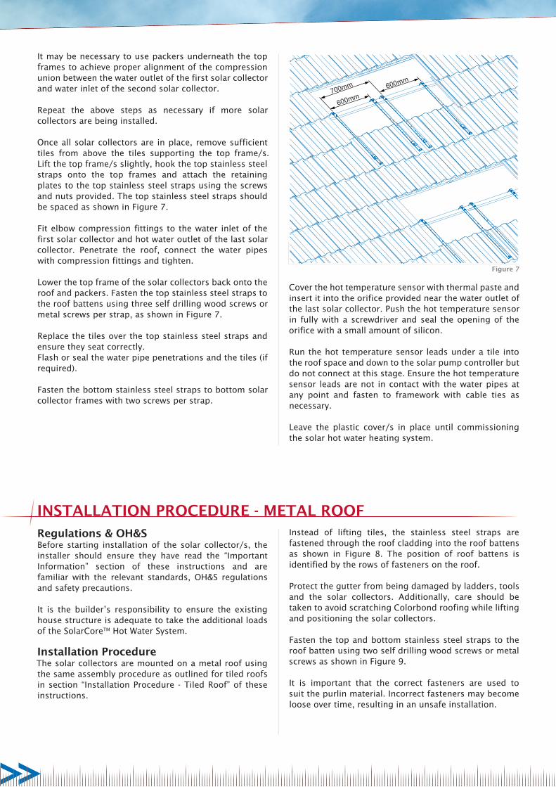
600mm600mm
700mm
Figure 7
Regulations & OH&SBefore starting installation of the solar collector/s, the installer should ensure they have read the “Important Information” section of these instructions and are familiar with the relevant standards, OH&S regulations and safety precautions.
It is the builder’s responsibility to ensure the existing house structure is adequate to take the additional loads of the SolarCoreTM Hot Water System.
Installation ProcedureThe solar collectors are mounted on a metal roof using the same assembly procedure as outlined for tiled roofs in section “Installation Procedure - Tiled Roof” of these instructions.
Instead of lifting tiles, the stainless steel straps are fastened through the roof cladding into the roof battens as shown in Figure 8. The position of roof battens is identified by the rows of fasteners on the roof.
Protect the gutter from being damaged by ladders, tools and the solar collectors. Additionally, care should be taken to avoid scratching Colorbond roofing while lifting and positioning the solar collectors.
Fasten the top and bottom stainless steel straps to the roof batten using two self drilling wood screws or metal screws as shown in Figure 9.
It is important that the correct fasteners are used to suit the purlin material. Incorrect fasteners may become loose over time, resulting in an unsafe installation.
INSTALLATION PROCEDURE - METAL ROOF
Cover the hot temperature sensor with thermal paste and insert it into the orifice provided near the water outlet of the last solar collector. Push the hot temperature sensor in fully with a screwdriver and seal the opening of the orifice with a small amount of silicon.
Run the hot temperature sensor leads under a tile into the roof space and down to the solar pump controller but do not connect at this stage. Ensure the hot temperature sensor leads are not in contact with the water pipes at any point and fasten to framework with cable ties as necessary.
Leave the plastic cover/s in place until commissioning the solar hot water heating system.
It may be necessary to use packers underneath the top frames to achieve proper alignment of the compression union between the water outlet of the first solar collector and water inlet of the second solar collector.
Repeat the above steps as necessary if more solar collectors are being installed.
Once all solar collectors are in place, remove sufficient tiles from above the tiles supporting the top frame/s. Lift the top frame/s slightly, hook the top stainless steel straps onto the top frames and attach the retaining plates to the top stainless steel straps using the screws and nuts provided. The top stainless steel straps should be spaced as shown in Figure 7.
Fit elbow compression fittings to the water inlet of the first solar collector and hot water outlet of the last solar collector. Penetrate the roof, connect the water pipes with compression fittings and tighten.
Lower the top frame of the solar collectors back onto the roof and packers. Fasten the top stainless steel straps to the roof battens using three self drilling wood screws or metal screws per strap, as shown in Figure 7.
Replace the tiles over the top stainless steel straps and ensure they seat correctly. Flash or seal the water pipe penetrations and the tiles (if required).
Fasten the bottom stainless steel straps to bottom solar collector frames with two screws per strap.

Strap trimmed to shorter length
Strap fixed with two Hex head self-drilling screws
600mm
600mm
700mm
Figure 8 Figure 9
Roof Mount Tilt Kit PreparationsMeasure the available mounting area to confirm frame orientation. Solar collectors are to be mounted in a portrait orientation only.
Determine the best orientation of the array to satisfy the following requirements:• Requirements of equator direction and tilt angle.• Maximise space for the number of solar collectors.• Mounting frame attachment to roof rafters and
battens.• Tilt frame bracing points.• Roof obstructions, chimneys, skylights, etc.
The rail length can be calculated using the following equation.A = Width of the Solar Collector (700mm)Q= Number of solar panels to be mounted to the railRAIL LENGTH = (QxA) + (50x2) + ((Q-1) x24) Example;RAIL LENGTH = (4x700) + (50x2) + ((4-1)x24) = 2972mm
The roof members must be inspected and be of suitable type and in sound condition.
Layout Rules• Maximum roof height limited to 10m.• Connections to be made down to existing roof
structure, through the roof batten into the rafter, or at a maximum spacing of 150mm from the rafter. It is the builder’s responsibility to reinforce the connection between the roof batten and the rafter.
• Maximum overhang of the rail from the bracket attachment to the house rafter is 400mm.
• Minimum of 2 screws per bracket into the house roof for timber and steel frame housing. Refer to note for additional information regarding connection of roof mount tilt frames in Region B.
• The maximum distance between mounting brackets is 1500mm in Region A, 1200mm for timber trusses and 1500mm for steel trusses in Region B.
NOTE: In Region B, Terrain Category 1, where roof mount tilt kits are attached to steel framing, the steel framing rafter spacing is limited to maximum 1200mm.
Regulations & OH&SBefore starting construction and installation the installer should ensure they have read the “Important Information” section of these instructions and are familiar with the relevant standards, OH&S regulations and safety precautions.
Double check all dimensions, levels and bolting locations before cutting, screwing or bolting structural members.
It is the builder’s responsibility to ensure the existing house structure is adequate to take the additional loads of the SolarCoreTM Hot Water System, and that the persons erecting the structure have had some previous building experience because some modifications to the existing house structure are required.
Attach to an Existing StructureThe builder or council is to ensure the existing house/structure is limited to a roof height of 10m, and of a suitable structural integrity that complies with all the relevant Australian Building codes and standards.
For more information regarding the suitability of the house structure to accommodate the solar collectors and mounting frame, consult a structural engineer or a building authority.
It is the builders responsibility to ensure that the existing house roof structure is strengthened correctly.
Planning PreparationThe portrait orientation of the solar collector array is to be mounted facing the equator and tilted at an angle equal to the sites latitude, from horizontal.
The solar collectors are not to be partially or fully shaded by surrounding obstructions.
All mounting brackets must be fixed to the existing roof rafter, or at a maximum distance of 150mm from the rafter, through the roof batten.
INSTALLATION PROCEDURE - ROOF MOUNT TILT KIT
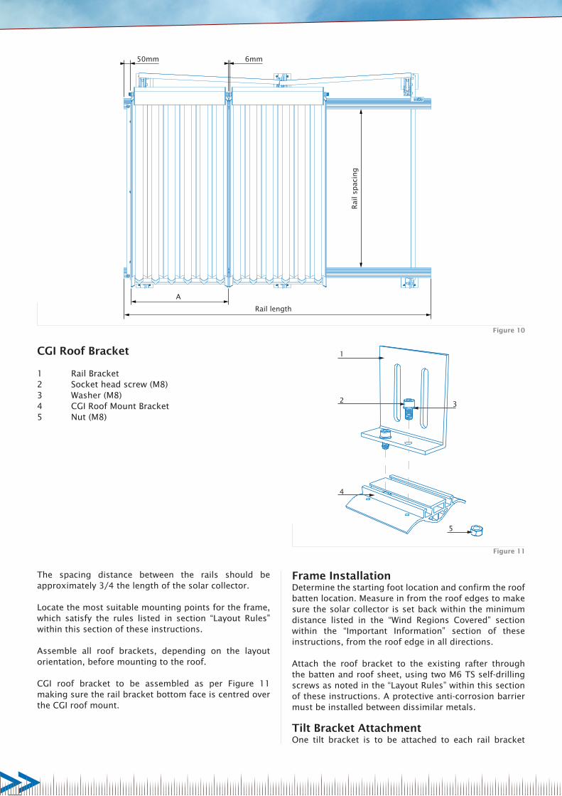
CGI Roof Bracket
1 Rail Bracket2 Socket head screw (M8)3 Washer (M8)4 CGI Roof Mount Bracket5 Nut (M8)
1
2 3
4
5
Figure 11
A
Rail length
Rai
l sp
acin
g
6mm50mm
Figure 10
Frame InstallationDetermine the starting foot location and confirm the roof batten location. Measure in from the roof edges to make sure the solar collector is set back within the minimum distance listed in the “Wind Regions Covered” section within the “Important Information” section of these instructions, from the roof edge in all directions.
Attach the roof bracket to the existing rafter through the batten and roof sheet, using two M6 TS self-drilling screws as noted in the “Layout Rules” within this section of these instructions. A protective anti-corrosion barrier must be installed between dissimilar metals.
Tilt Bracket AttachmentOne tilt bracket is to be attached to each rail bracket
The spacing distance between the rails should be approximately 3/4 the length of the solar collector.
Locate the most suitable mounting points for the frame, which satisfy the rules listed in section “Layout Rules” within this section of these instructions.
Assemble all roof brackets, depending on the layout orientation, before mounting to the roof.
CGI roof bracket to be assembled as per Figure 11 making sure the rail bracket bottom face is centred over the CGI roof mount.

Upright rail
Tilt bracket
Second framing rail
Figure 15
Rail channel
M10 socket screw & rail nut combination
Figure 14
Loosen and adjust screw heights to determine ‘tilt’ angle
Figure 13
Rail bracket
Tilt bracket Two M10 socket screws & nuts
Figure 12
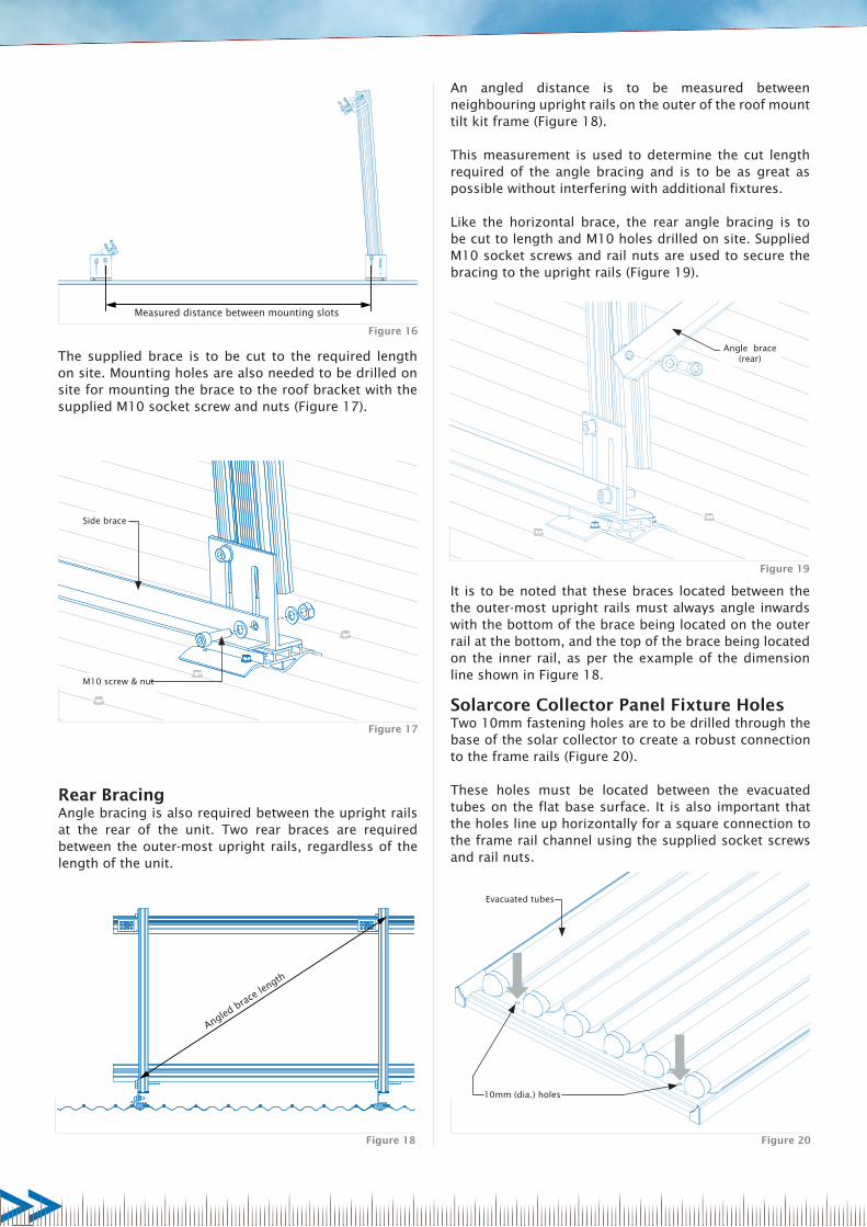
Side BracingAngle braces are to be attached to the roof bracket, spanning between the front and rear roof brackets at either end of the roof mount tilt kit unit for increased stability.
The horizontal distance between the mounting holes on the roof brackets is to be measured to gauge the length required for the brace (Figure 16).
This process is to be replicated for each roof bracket, with positioning reproduced accurately.
Position tilt brackets towards the top of the upright rails using the supplied screws and rail nuts (Figure 15). This must be completed on each upright rail. These tilt brackets will support the second horizontal frame rail.
When the framing rail is supported by the upright rails and tilt brackets, measure to be sure a consistent, parallel distance between framing rails is found. Tighten all mounting screws on the rails and roof brackets.
This can be assisted by fixing a brace between the first and second frame rail at one end to stop the frame from tipping, thereby keeping a square alignment.
Upright Rail PositioningPosition a series of roof brackets corresponding to the front row at the distance required to span the batten distance.
Upright supports are to be cut to length from the supplied frame rail with one upright required for each rear roof bracket. Uprights are to be positioned in a manner that allows for a channel facing towards the roof bracket, and also facing outwards (Figure 14). Rail nuts and socket screws are used to mount the upright to the roof bracket.
(Figure 12). This will allow the framing rail to attach in the desired orientation. The tilt bracket angle will define the tilt of the mount and is altered through positioning adjustments to the M10 socket screws (Figure 13). Replicate this process to create an even row of roof brackets.
Attach the rail to the tilt brackets, using the supplied screws and rail nut. The maximum overhang of the rail from the roof bracket is 400mm. Attach a roof bracket to the other end of the rail and slide into position, ready for fastening.
Recheck the rail is parallel to the roof edge. Continue installing the roof brackets and rails, as previously described, while making sure that all subsequent rails are square and parallel to the first rail. Tighten all mounting screws on the rails and roof brackets.
10mm (dia.) holes
Evacuated tubes
Figure 20
Angle brace(rear)
Figure 19
Angled brac
e len
gth
Figure 18
Side brace
M10 screw & nut
Figure 17
Measured distance between mounting slots
Figure 16
Solarcore Collector Panel Fixture HolesTwo 10mm fastening holes are to be drilled through the base of the solar collector to create a robust connection to the frame rails (Figure 20).
These holes must be located between the evacuated tubes on the flat base surface. It is also important that the holes line up horizontally for a square connection to the frame rail channel using the supplied socket screws and rail nuts.
Rear BracingAngle bracing is also required between the upright rails at the rear of the unit. Two rear braces are required between the outer-most upright rails, regardless of the length of the unit.
An angled distance is to be measured between neighbouring upright rails on the outer of the roof mount tilt kit frame (Figure 18).
This measurement is used to determine the cut length required of the angle bracing and is to be as great as possible without interfering with additional fixtures.
Like the horizontal brace, the rear angle bracing is to be cut to length and M10 holes drilled on site. Supplied M10 socket screws and rail nuts are used to secure the bracing to the upright rails (Figure 19).
It is to be noted that these braces located between the the outer-most upright rails must always angle inwards with the bottom of the brace being located on the outer rail at the bottom, and the top of the brace being located on the inner rail, as per the example of the dimension line shown in Figure 18.
The supplied brace is to be cut to the required length on site. Mounting holes are also needed to be drilled on site for mounting the brace to the roof bracket with the supplied M10 socket screw and nuts (Figure 17).

Angle brace
Collector
10mm (dia.) holes
M10 socket screw(through to rail)
Figure 24
New nipple(used as connector)
Collector brass nut
Figure 23
Nipple removal
Collector brass nut
Figure 22
M10 socket screw(through to frame rail)
Figure 21
Piping ConnectionsThe brass nuts and adaptors bridging the solar collector panels must be connected using the supplied nipples.
Removal of the existing nipple is necessary (Figure 22) before attaching the new nipple (Figure 23).
NOTE: Thread tape is required on each threaded connection.
End BracketsThe end two solar collector panels are secured furthermore using angle bracing bridging the upper and lower frame rail (Figure 24).
Angle bracing is to be trimmed on site to the measured length with 10mm holes (dia.) drilled on one face in the appropriate locations at each end. M10 socket screws and rail nuts are used to secure the angle brace to the frame rails (Figure 24).
It is important to keep the angle brace flat on and square to both the frame rail and the side of the solar collector panel when tightening the rail nuts.
When all inlet and outlet nuts are threaded firmly and the solar collector panels are in the desired position, tightly fasten the rail nuts connecting the solar collector to the lower frame rail.
Attach a ½” nut (not supplied) to the nipples on the outer collectors. Connect the ½” to the 3/8” adaptor (supplied) and then to the nipples on the outer collectors. Connect 10mm (3/8”) copper pipe to the inlet of the first collector and outlet of the final collector.
When the installer is drilling the holes in the collector panel, care must be taken to not damage the solar collector flashing or evacuated tubes.
The solar collector panels are to be mounted to the roof mount tilt kit, whilst loosely fastening the rail nuts in to the lower rail (Figure 21). This will assist in stabilising the mount.
It is important at this time to check that the solar collector panels are resting flat on both the upper and lower frame rail. The lower rail should be flat if all rail nuts are within the frame rail correctly.
The upper rail may need to be adjusted at the tilt brackets to create a flat connection between the solar collector panels and the frame rail.

M10 socket screw (& washer)
M6 TS self-drilling screw
Angle bracket(right)
Angle bracket(left)
Figure 26
M6 TS self-drilling screw
Angle brace
M10 socket screw (& washer)
Rail nut
Collector
Figure 25
Angle Bracket FasteningAngle brackets are required to secure the top of the solar collectors to the upper frame rail. These angle brackets are to be created from the supplied angle bracing by cutting to a length of approx. 85mm (cut on site).
When both rail nuts are fastened, M6 TS self-drilling screws are needed to screw the brace to the solar collector frame.
Two to three screws can be used per brace, with placement being crucial as to not damage or penetrate the solar collector flashing or evacuated tubes. The TS screws are used to drill through the angle brace and to fasten only to the frame of the solar collector (Figure 25).
Securing a brace at one end will assist in aligning the solar collector panels and keeping the frame square and will also stop the solar collector panels from unintentional movement.
Electronic Controller Position (Indoor)The electronic controller should be mounted on an inside vertical surface, where it is protected from moisture and direct sunlight. A wall in the kitchen or laundry is ideal.
Electronic Controller Position (Outdoor)The electronic controller should be mounted on an outside vertical surface, where it is sheltered from direct sunlight and weather. A wall under the eaves is ideal.
The electronic controller should be mounted at chest height in a position where it can be easily accessed.
The electronic controller will require a 240V, 10A earthed power point.
IMPORTANT NOTEThe controller is factory programmed to the correct settings. These settings must not be altered.
To ensure frost protection the power must remain connected to the electronic controller and circulation pump.
Installation ProcedureThe mains power supply lead, circulation pump power lead, hot temperature sensor lead and cold temperature sensor lead are connected to the electronic controller.
The system installation diagrams shown in Figure 29 and Figure 30 detail the general arrangement of components, plumbing and wiring.
Please refer to the manufacturer’s instructions for the electronic controller installation and wiring connection details. Failure to follow the manufacturer’s instructions may cause failure of the electronic controller and will void the warranty.
IMPORTANT NOTE (INDOOR CONTROLLER)The second storage sensor TT and electric boost heating element are not connected to the electronic controller.
INSTALLATION OF ELECTRONIC CONTROLLER
A 10mm hole (dia.) must also be created on site on the appropriate face of each bracket (Figure 26).
Each solar collector attached to the mount requires both a left and right bracket to affix the panel to the unit.
The angle brackets are to be pushed hard against both the outer of the framing rail and also the inside face of the solar collector frame, then tightly fastened to the back of the frame rail using the supplied M10 socket screws and rail nuts.
When all brackets have been fastened into place, M6 TS self-drilling screws are used to drill through the bracket and into the solar collector frame, subsequently fastening the panels to the top rail (Figure 26).
The area of the solar collector frame to drill through is slight and the installer must be sure not to damage the solar collector when fastening.

Figure 27
Water Supply Piping
Solar Piping
Figure 28
Circulation Pump PositionThe circulation pump should be pipe mounted in a position that is sheltered from direct exposure to the sun and weather.
The pump cover should be fitted over the pump to prevent water coming in contact with the electrical cover.
The circulation pump must be mounted with the motor shaft horizontal and cable gland below the pump as shown in Figure 27.
Please refer to the manufacturer’s instructions for the circulation pump installation details.
INSTALLATION OF CIRCULATION PUMP
Failure to follow the manufacturer’s instructions may cause failure of the circulation pump and will void the warranty.
The power lead for the circulation pump is connected to the electronic controller.
Please refer to the manufacturer’s instructions for the electronic controller for wiring connection details.
The system installation diagrams shown in Figure 29 and Figure 30 show the general arrangement of components, plumbing and wiring.
INSTALLATION OF GAS BOOSTED STORAGE TANK
Regulations & OH&SBefore starting installation of the hot water storage tank and gas booster, the installer should ensure they have read the “Important Information” section of these instructions and are familiar with the relevant standards, OH&S regulations and safety precautions listed.
Hot Water Storage Tank LocationThe hot water storage tank should be located as close as possible to the most frequently used hot water outlets to minimise water wastage and heat loss. Also consider that the solar collectors should be mounted as close as possible to the hot water storage tank to minimise pipe runs and heat loss.
The hot water storage tank has an ingress protection rating of IPX4 and is suitable for internal or external installation.
For external installation, the hot water storage tank should be mounted on a concrete base at least 50 mm thick in accordance with AS/NZS 3500.4 clause 4.5.3, or on well seasoned, evenly spread hardwood slats at least 25mm thick.
For internal installations, or where water leakage may cause property damage, the hot water storage tank should be installed with an approved safe tray in accordance with AS/NZS 3500.4 clause 4.4. This will prevent property damage in the event of a leak and will allow draining of the hot water storage tank for maintenance.
Ensure the hot water storage tank does not stand on wet surfaces.
The gas boosted hot water storage tank will require a cold water supply as outlined in the “Water Supply” section in this section of these instructions.
All system components must be located for accessibility.
The hot water storage tank must be accessible without ladders or scaffolding. Clearance must be provided for access to and removal of all serviceable parts including P&TR valve, circulating pump and gas booster (where fitted to tank).
Warning signs and information on rating plates must be visible.
Number of Collectors 2 3
DN 15 pipes 40m 30m
Table 13
Water SupplyApproved pressure limiting valves rated at 500kPa are required if the mains water supply pressure exceeds 500kPa.
The gas booster will not achieve the maximum rated flow if the mains water supply pressure is below the minimum supply pressure specified for the gas booster in Table 7 “Gas Boosters Specifications”. The system will operate at lower pressures but will deliver hot water at lower flow rates.
Water chemistry and impurity limits are specified under “Water Quality” in the “Important Information” section of these instructions. Metropolitan water supplies generally meet these requirements. Please contact the relevant water supply authority or have the water tested if uncertain about the water supply quality.
If necessary, a suitable filter or water softener should be fitted in the mains water supply to achieve the required water quality.
For locations with high sediment levels in the water supply, the hot water storage tank should be flushed at regular intervals. Stratco recommend that a drain cock is fitted at the cold water inlet to the hot water storage tank.
Water Pipes, Valves & FittingsAll hot water pipes must be insulated with thermal lagging such as Polyethylene foam to reduce heat loss and maximise performance of the solar hot water heating system.
All pipe sizes should conform to AS/NZS 3500 except collector flow and return pipes.
Solar collector flow and return pipes should be 15mm copper tube to withstand the high pressures and temperatures that occur. Maximum recommended total lengths for the cold water flow and hot water return pipes are shown in Table 13.
The pressure and temperature relief (P&TR) valve is a safety device and must be fitted to the hot water storage tank. The P&TR valve supplied is rated at 10.0kW, which must exceed the thermal load applied to the hot water storage tank. For gas boosted solar hot water heater systems, the thermal load is applied by the solar collectors only. The gas booster does not apply thermal load to the hot water storage tank.
A cold water expansion control valve (ECV) rated at 700kPa must be fitted to the cold water supply of the hot water storage tank. This will reduce hot water discharge resulting in wear of the P&TR valve.
Approved pressure limiting valves rated at 500kPa must be fitted if the mains water supply pressure exceeds 500kPa.
A combination non-return/isolating valve and strainer is fitted to the cold water supply of the hot water storage tank.
Gas boosters for Stratco SolarcoreTM hot water heating systems are preset to deliver hot water at 70°C in accordance with plumbing regulations. A temperature limiting device, such as thermostatic mixing or tempering valves, must be fitted to limit the hot water temperature
For vitreous enamel hot water storage tanks, allow a clearance of one cylinder height above the hot water storage tank to allow inspection and replacement of the sacrificial anode.
Gas Booster LocationThe gas booster is designed for outdoor installation only, and must be located in a position where wind and natural convection will disperse gas leakage and combustion products.
The gas booster must be mounted on a vertical surface with the water and gas connections underneath. In most installations the gas booster is mounted directly on the hot water storage tank.
If the gas booster is not mounted on the hot water storage tank, ensure that the wall or structure on which it will be mounted is capable of supporting the weight of the gas booster and associated plumbing. The weight of the gas booster models is specified in Table 7 “Gas Boosters Specifications”.
The location of the gas booster terminal flue must be in accordance with AS 5601 Figure 5.3.
Refer to AS 5601 for specific requirements in relation to gas boosters installed on elevated structures or under floors.
The gas booster will require a gas supply as outlined in the “Gas Supply” section of these instructions and a 240V, 10A earthed weather proof power point.
Gas SupplyThe gas meter and regulator must be rated for the maximum flow of the gas booster in addition to all other gas appliances on the premises. Please refer to the manufacturer’s instructions for the gas booster to determine maximum gas consumption and required gas pressure.
It is the installers responsibility to ensure gas meter, regulator and pipework are functional, sized correctly and rectify as necessary.
Gas pipe sizing must conform to the sizing chart in AS 5601. If pipe sizes are not sufficient, the gas booster will not achieve full heating performance.
An approved full flow isolation valve and disconnection union must be fitted to the gas inlet of the gas booster.

to 50°C or 45°C where the hot water is supplied to areas used for personal hygiene such as bathrooms and ensuites. Please refer to AS/NZS3500.4 for temperature limits for facilities such as child minding centres, schools and nursing homes.
IMPORTANT NOTEA hot water non-return valve must be fitted as shown in Figures 29 & 30 to prevent hot water flowing to the cold inlet of the tempering valve during stagnation conditions. Failure to fit this non-return valve can result in excessive tank noise or scalding when a hot tap is opened during stagnation conditions.
Installation ProcedurePosition and install the solar collectors as outlined in “Solar Collector Position & Orientation” of these instructions.
Position and install the electronic controller as outlined in “Installation of Electronic Controller” of these instructions. Please refer to the manufacturer’s instructions for the electronic controller installation and wiring connection details. Failure to follow the manufacturer’s instructions may cause failure of the electronic controller and will void the warranty.
Position the hot water storage tank (and safe tray if required) as outlined in “Hot Water Storage Tank Location” within this section of these instructions. Please refer to the manufacturer’s instructions for the hot water storage tank installation details. Failure to follow the manufacturer’s instructions may cause failure of the hot water storage tank and will void the warranty.
Using the brackets provided, mount the gas booster on the hot water storage tank (only if positioned outside) or on an outside wall as outlined in “Gas Booster Location” within this section of these instructions. Please refer to the manufacturer’s instructions for the gas booster installation details. Failure to follow the manufacturer’s instructions may cause failure of the gas booster and will void the warranty.
Fit a suitable disconnection union and isolation valve to the gas inlet of the gas booster and connect to the gas supply. Please refer to “Gas Supply” within this section of these instructions for gas supply details. Purge the gas supply lines before final connection to remove air and swarf. Test for gas leaks.
Fit the 15mm Pressure & Temperature Relief (P&TR) valve to the connection marked “P&TR valve” near the top of the tank. Use Teflon thread tape and ensure the tape does not protrude past the end of the thread to prevent risk of valve blockage. Tighten the P&TR valve using the spanner flats and leave the valve outlet pointing down.
Fit the pressure limiting valve (where required), non-return/isolating valve/strainer, expansion control valve and tee to the cold water inlet connection at the bottom of the hot water storage tank. A pressure limiting valve is required if the water supply pressure exceeds 500kPa.
Fit the solar collector flow pipe and insulation between the cold water supply pipe tee and the water and insulation inlet of the first solar collector. Fit the solar assembly non-return valve to the outlet of the circulation pump.
Pipe mount the circulation pump, with valves attached, at a suitable location in the solar collector flow pipe as outlined in “Installation of Circulation Pump” of these instructions.
Please refer to the manufacturer’s instructions for the circulation pump installation details. Run the circulation pump power cable to the electronic controller and connect it to the pump terminals specified in the manufacturer’s instructions for the electronic controller.
Fit the solar collector return pipe and insulation between the water outlet of the last solar collector and the connection marked “solar return” on the hot water storage tank.
Cover the cold temperature sensor with thermal paste for improved heat conduction. Fit the cold temperature sensor into the immersion sleeve at the bottom of the tank and seal with silicon.
Run the cold temperature sensor lead to the temperature differential controller and connect it to the cold temperature sensor terminals specified in the manufacturer’s instructions for the temperature differential controller. Ensure the cold temperature sensor lead is not in contact with the hot water pipes at any point and fasten to framework with cable ties as necessary.
Connect 15mm copper tube drain lines to the drain outlets of the ECV and P&TR valves. Drain lines must be open to atmosphere and slope continuously down to a visible drain point, preferably over a drain. Drain lines must be less than 9 metres long, free of restrictions and other valves and positioned to prevent freezing.
Fit the mains water supply pipe from the mains water supply to the cold water inlet of the hot water storage tank and purge before final connection to remove air and swarf.
Fit Dn20 copper tube and 20mm thick insulation between the hot water outlet of the hot water storage tank and the cold water inlet of the gas booster.
Fit the hot water supply pipe from the hot water outlet of the gas booster to the pipe supplying hot water to the building. A temperature limiting device is required as outlined in “Water Pipes, Valves and Fittings” within this section of these instructions. The installation of the gas boosted Stratco SolarcoreTM hot water heating system is now complete. Please follow the commissioning procedure in
“Commissioning” of these instructions carefully to ensure the gas boosted solar hot water heating system functions correctly.
TCTS 51.4
68.3
18
2
3
4
6
7
19
820109
14
13
15
16
17
12
21
21
5
1
Supplied in Kit1. Hot temperature sensor3. Gas boosted storage tank4. Gas booster13. Electronic controller14. Cold temperature sensor15. P&TR valve 15mm16. Solar non-return valve assembly17. Circulation pump18. Solar collectors
Supplied by Installer2. DN15 Solar return pipe, insulation & connections5. DN20 copper tube, 20mm thick insulation & connections6. Gas supply pipe / Isolating valve / Disconnection union & fittings7. Tempered water pipe & connections8. Expansion control valve9. Non-return isolating valve10. Pressure limiting valve11. DN15 Water supply pipe & connections12. DN15 Solar flow pipe, insulation & connections19. Tempering valve20. Hot water non-return valve21. 240V Power
Figure 29

Number of Collectors 2 3
DN 15 pipes 40m 30m
Table 14
It is the electrician’s responsibility to ensure the wiring to the electric boosted solar hot water heating elements is capable of withstanding the electrical load. Please refer to “Electric Boosted Vitreous Enamel Storage Tank” for power ratings of the electric heating elements.
Water SupplyApproved pressure limiting valves rated at 500kPa are required if the mains water supply pressure exceeds 500kPa.
Water chemistry and impurity limits are specified under “Important Information” in these instructions. Metropolitan water supplies generally meet these requirements. Please contact the relevant water supply authority or have the water tested if uncertain about the water supply quality.
If necessary, a suitable filter or water softener should be fitted in the mains water supply to achieve the required water quality. For locations with high sediment levels in the water supply, the hot water storage tank should be flushed at regular intervals. Stratco recommend that a drain cock is fitted at the cold water inlet to the hot water storage tank.
Water Pipes, Valves & FittingsAll hot water pipes must be insulated with thermal lagging such as Polyethylene foam to reduce heat loss and maximise performance of the solar hot water heating system. All pipe sizes should conform to AS/NZS 3500 except collector flow and return pipes.
Solar collector flow and return pipes should be 15mm copper tube to withstand the high pressures and temperatures that occur. Maximum recommended total lengths for the cold water flow and hot water return pipes are shown in Table 14.
INSTALLATION OF ELECTRIC BOOSTED STORAGE TANKRegulations & OH&SBefore starting installation of the hot water storage tank with electric booster, the installer should ensure they have read the “Important Information” section of these instructions and are familiar with the relevant standards, OH&S regulations and safety precautions listed.
Hot Water Storage Tank LocationThe hot water storage tank should be located as close as possible to the most frequently used hot water outlets to minimise water wastage and heat loss. Also consider that the solar collectors should be mounted as close as possible to the hot water storage tank to minimise pipe runs and heat loss.
The hot water storage tank has an ingress protection rating of IPX4 and is suitable for internal or external installation. For external installation, the hot water storage tank should be mounted on a concrete base at least 50 mm thick in accordance with AS/NZS 3500.4 clause 4.5.3, or on well seasoned, evenly spread hardwood slats at least 25 mm thick.
For internal installations, or where water leakage may cause property damage, the hot water storage tank should be installed with an approved safe tray in accordance with AS/NZS 3500.4 clause 4.4. This will prevent property damage in the event of a leak and will allow draining of the hot water storage tank for maintenance.
Ensure the hot water storage tank does not stand on wet surfaces. The electric boosted hot water storage tank will require a cold water supply as outlined in “Water Supply” within this section of these instructions and an independent 240V power supply installed at the switch board as outlined in “Electricity Supply” within this section of these instructions.
All system components must be located for accessibility. The hot water storage tank must be accessible without ladders or scaffolding. Clearance must be provided for access to and removal of all serviceable parts including P&TR valve, circulating pump and electric heating elements. Warning signs and information on rating plates must be visible.
For vitreous enamel hot water storage tanks, allow a clearance of one cylinder height above the hot water storage tank to allow inspection and replacement of the sacrificial anode.
Electricity SupplyAll electric boosted solar hot water heating elements must be connected to an independent, fused AC 240V, 50 Hz power supply with an isolating switch installed at the switch board.
Electrical connection must be carried out by a licensed electrician in accordance with AS/NZS 3000 Electrical Installations.
The pressure and temperature relief (P&TR) valve is a safety device and must be fitted to the hot water storage tank. The P&TR valve supplied is rated at 10.0kW, which must exceed the thermal load applied to the hot water storage tank. For electric boosted solar hot water heater systems, the thermal load is applied by the solar collectors and the electric heating elements.
A cold water expansion control valve (ECV) rated at 700kPa must be fitted to the cold water supply of the hot water storage tank. This will reduce hot water discharge resulting in wear of the P&TR valve. Approved pressure limiting valves rated at 500kPa must be fitted if the mains water supply pressure exceeds 500kPa. A combination non-return/isolating valve and strainer is fitted to the cold water supply of the hot water storage tank.

Pipe mount the circulation pump, with valves attached, at a suitable location in the solar collector flow pipe as outlined in “Installation of Circulation Pump” of these instructions. Please refer to the manufacturer’s instructions for the circulation pump installation details. Run the circulation pump power cable to the electronic controller and connect it to the pump terminals specified in the manufacturer’s instructions for the electronic controller.
Fit the solar collector return pipe and insulation between the water outlet of the last solar collector and the connection marked “solar return” on the hot water storage tank. Cover the cold temperature sensor with thermal paste for improved heat conduction. Fit a tee and sensor immersion sleeve to the cold water inlet of the tank and insert the cold temperature sensor. Tighten the gland nut until the sensor cable is sealed firmly.
Run the cold temperature sensor lead to the temperature differential controller and connect it to the cold temperature sensor terminals as in the manufacturer’s instructions for the temperature differential controller. Ensure the cold temperature sensor lead is not in contact with the hot water pipes at any point and fasten to framework with cable ties as necessary.
Connect 15mm copper tube drain lines to the drain outlets of the ECV and P&TR valves. Drain lines must be open to atmosphere and slope continuously down to a visible drain point, preferably over a drain. Drain lines must be less than 9 metres long, free of restrictions and other valves and positioned to prevent freezing.
Fit the mains water supply pipe from the mains water supply to the cold water inlet of the hot water storage tank and purge before final connection to remove air and swarf. Fit the hot water supply pipe from the hot water outlet of the hot water storage tank to the pipe supplying hot water to the building. A temperature limiting device is required as outlined in “Water Pipes, Valves and Fittings” within this section of these instructions.
Connect the power supply wires from the switch board, as outlined in “Electricity Supply” within this section of these instructions, directly to the terminal block and earth tab connections inside the electrical cover of the hot water storage tank. Use a flexible 20mm conduit and connect with a 20mm terminator.
The electricity supply for single element heaters can be either off-peak, extended off-peak or continuous depending on tariffs available from the local electricity supply authority. The thermostat should be set at 60°C in accordance with Australian Standards.
Please refer to the manufacturer’s instructions for the electric boosted hot water storage tank wiring diag. & connection details. The installation of the electric boosted Stratco SolarcoreTM hot water system is now complete. Follow the commissioning procedure carefully to ensure the electric boosted solar hot water heating system functions correctly.
Thermostats for electric boosted Stratco SolarcoreTM hot water heating systems are preset to 60°C in accordance with plumbing regulations. A temperature limiting device, such as thermostatic mixing or tempering valves, must be fitted to limit the hot water temperature to 45°C or 50°C where the hot water is supplied to areas used for personal hygiene such as bathrooms and ensuites.
Please refer to AS/NZS3500.4 for temperature limits for facilities such as child minding centres, schools and nursing homes.
IMPORTANT NOTEA hot water non-return valve must be fitted as shown in Figures 29 & 30 to prevent hot water flowing to the cold inlet of the tempering valve during stagnation conditions. Failure to fit this non-return valve can result in excessive tank noise or scalding when a hot tap is opened during stagnation conditions.
Installation ProcedurePosition and install the solar collectors as outlined in “Solar Collector Position & Orientation” of these instructions.
Position and install the electronic controller as outlined in “Installation of Electronic Controller” of these instructions. Please refer to the manufacturer’s instructions for the electronic controller installation and wiring connection details. Failure to follow the manufacturer’s instructions may cause failure of the electronic controller and will void the warranty.
Position the hot water storage tank (and safe tray if required) as outlined in “Installation of Electric Boosted Storage Tank” of these instructions. Please refer to the manufacturer’s instructions for the hot water storage tank installation details. Failure to follow the manufacturer’s instructions may cause failure of the hot water storage tank and will void the warranty.
Fit the Pressure & Temperature Relief (P&TR) valve to the connection marked “P&TR valve” near the top of the tank as shown in Figure 30. Use Teflon thread tape and ensure the tape does not protrude past the end of the thread to prevent risk of valve blockage. Tighten the P&TR valve using the spanner flats and leave the valve outlet pointing down.
Fit the pressure limiting valve (where required), non-return/isolating valve/strainer, expansion control valve and pipe tee to the cold water inlet connection at the bottom of the hot water storage tank. A pressure limiting valve is required if the water supply pressure exceeds the specifications for the hot water storage tanks in “Electric Boosted Vitreous Enamel Storage Tank” .
Fit the solar collector flow pipe and insulation between the cold water supply pipe tee and the water inlet of the first solar collector. Fit the non-return valve and flow regulator to the outlet of the circulation pump.

TCTS 51.4
68.3
3
18
6
5
4
17
19
19
87
12
11
13
14
15
9
16
2
10
1
20
Supplied by Installer2. DN15 Solar returm pipe, insulation & connections4. Tempered water pipe connections6. Expansion control valve7. Non-return isolating valve8. Pressure limiting valve9. DN15 Water supply pipe & connections10. DN15 Solar flow pipe, insulation & connections17. Tempering valve18. Hot water non-return valve19. 240V Power
Supplied in Kit1. Hot temperature sensor3. Electric boosted storage tank5. Electric element11. Electronic controller12. Cold temperature sensor13. P&TR valve (15mm)14. Solar non-return valve assembly15. Circulation pump16. Solar collectors20. Sensor immersion sleeve
Figure 30

</-
Set
</+
MM 4SET
Figure 31 - Indoor Controller
COMMISSIONING
Filling the SystemEnsure building occupants are warned to stay clear of the solar hot water heating system components and pipe work as hot water or steam may be discharged.
For gas boosted Stratco SolarcoreTM hot water heating systems, switch off the electric power supplies to the gas booster and electronic controller and close the isolating valve on the gas supply to the gas booster.
For electric boosted Stratco SolarcoreTM hot water heating systems, switch off the electric power supplies to the electric heating elements and electronic controller.
Open the hot water tap at the closest sink or basin. Open the isolating valve on the cold water supply to the hot water storage tank. The entire solar hot water heating system will now fill with cold water and expel air through the hot water tap.
Close the hot water tap at the sink or basin when water flows continuously without air bubbles or air bursts. Open the next closest hot water tap and close when water flows continuously without air bubbles or air bursts. Continue opening and closing hot water taps until all pipes have been purged of air.
Check all connections for leaks and tighten or repair if necessary. Operate the easing gear on the ECV and P&TR valves on the hot water storage tank to ensure the valves are functional.
Circulating Pump & Electronic ControllerTurn on the power supply to the electronic controller and wait for the controller to complete the initialisation phase. The circulating pump can then be turned on manually as follows:INDOOR CONTROLLER• Press the “>/+” button until the display shows AC 1.• Press the “SET” button and the word “SET” begins
flashing. • Press the “>/+” button until the display shows AC 12. • Press the “SET” button again to accept the value and
the word “SET” stops flashing. • Press the “>/+” button until the display shows MM 4. • Press the “SET” button and the word “SET” begins
flashing.• Press the “</-” button until the display shows MM 1.• Press the “SET” button again to accept the value and
the word “SET” stops flashing. • The LED flashes red/green to show the pump is
running.• Press the “</-” button to exit the settings menue,
until “TC” and “TS” are shown in the display. OUTDOOR CONTROLLER• Press and hold the pump button.
The circulating pump should now run continuously. This can be confirmed by checking the flow meter on the solar non-return valve assembly. The flow rate must be adjusted to 1.0LPM by turning the screw and aligning
the bottom fo the float with the 1LPM mark on the flow meter. If the pump does not operate, check all wiring and connections to the controller and pump. If the wiring is correct and the pump still does not operate, turn off power to the temperature differential controller and contact your Stratco representative.
When correct pump operation has been confirmed, return the Indoor Controller to fully automatic mode using the above procedure and changing the operating mode “MM” to “4”. Important - do not leave the pump running in manual mode. Confirm freeze protection and temperature settings.
IMPORTANT NOTEThe controller is factory programmed to the correct settings. These settings must not be altered.
Gas BoosterThis section applies for gas boosted Stratco SolarcoreTM hot water heating systems only.
Ensure the isolating valve on the gas supply to the gas booster is closed. Remove the test point screw on the gas inlet connection of the gas booster and attach a pressure gauge.
Turn on the power supply to the gas booster but not the temperature differential controller. Open the isolating valve on the gas supply to the gas booster. Ensure the isolating valve on the cold water supply to the hot water storage tank is open.
Ensure building occupants are warned to stay clear and then open all hot water taps.
Operate all other gas appliances at their maximum gas consumption. The gas pressure gauge should read between 1.13 and 3.0kPa for Natural Gas and between 2.75 and 3.0kPa for LPG. If the gas pressure is lower, the gas supply is inadequate and the gas booster will not achieve full heating performance. It is the installers responsibility to ensure gas meter, regulator and pipe-work are funtional, sized correctly and rectified as necessary.
When correct gas pressure has been confirmed, close all hot water taps and return all gas appliances to their original settings.
Measure the hot water delivery temperature with a suitable thermometer at an untempered outlet closest to the gas booster. The temperature should be between 65°C and 70°C.Measure the hot water delivery temperature with a suitable thermometer at a tempered outlet. The temperature should be 45°C or 50°C as outlined in section “Water Pipes, Valves and Fittings” within this section of these instructions.
Close the isolating valve on the cold water supply to the hot water storage tank. Inspect and clean the strainers at the isolating valve and gas booster inlet.
Solar CollectorCheck that the solar collectors are correctly anchored to the roof and that all tiles and flashings/seals are in place.
Check that hot and cold temperature sensors are correctly positioned and the leads are free of cuts and damage. Remove plastic covers from the solar collector/s.
For gas boosted Stratco SolarcoreTM hot water heating systems, turn on the power supply to the gas booster and the temperature differential controller. Ensure the isolating valve on the cold water supply and the isolating valve on the gas supply to the gas booster are both open.
For electric boosted Stratco SolarcoreTM hot water heating systems, turn on the power supply to the electric heating element/s and the temperature differential controller. Ensure the isolating valve on the cold water supply is open.
Solar heating of the water in the hot water storage tank will now commence automatically when there is sufficient sunlight.
HandoverOnce commissioning has been successfully completed, show the owner the main Stratco SolarcoreTM hot water heating system components and explain their correct operation as outlined in “Operation” section of these instructions. Also explain the importance of correct maintenance as outlined in “Maintenance” section of these instructions.
Complete the installation report form and fax it to Stratco.
Complete the RECs assignment form in conjunction with the owner and fax it to Stratco.
Leave this instruction manual with the owner and ask them to complete the warranty form and return it to Stratco.
For longer absences, the electric element or gas booster can be turned off as follows:• For electric boosted systems, switch off the electricity
supply to the electric boost heating element in the electricity meter box. To ensure frost protection do not switch off the power points for the electronic controller, circulating pump or the water supply.
• For gas boosted systems, switch off the power points for the gas booster. To ensure frost protection do not switch off the power point for the electronic controller and circulating pump or the water supply.
During extended absences in summer it is advisable to cover the solar collector to avoid overheating the system and dumping hot water from the P&TR valve.
Turning On the Stratco SolarCoreTM Hot Water System After HolidaysFor electric boosted systems, switch on the electricity supply to the electric boost heating element in the electricity meter box. Check that the power points for the electronic controller and circulating pump are still turned on. Remove covers from the solar collectors if covered. Electric heating will commence automatically but it may take several hours before hot water is available.
For gas boosted systems, switch on the power point for the gas booster. Check that the power point for the electronic controller and circulating pump is still turned on. Remove covers from the solar collectors if covered. Hot water will be available immediately from the gas booster.
General UseThe Stratco SolarcoreTM hot water heating system is designed to automatically provide a continuous supply of hot water, while maximising the environmental benefits and energy cost savings achieved with solar heating.
The electronic controller automatically switches the solar heating function on when there is sufficient heat available from the sun. When the water in the hot water storage tank reaches 65°C the electronic controller switches off the solar heating function and protects the hot water storage tank from overheating.
The electronic controller also automatically protects the solar collectors from damage during freezing weather conditions.
During periods when there is insufficient heat available from the sun, the gas boost heater or electric boost element will automatically provide all the heat necessary to ensure a continuous supply of hot water.
Apart from the regular care outlined in “Regular Care” within the “Maintenance” section of these instructions, there is no action needed by the user of the solar hot water heating system. All the user needs to do is open a tap or turn on an appliance to enjoy the benefits of solar heated hot water.
Turning Off the Stratco SolarCoreTM Hot Water System for HolidaysIf the premises will be unoccupied for a few days, Stratco recommend that the solar hot water heating system is left switched on.
OPERATION

Problem Cause Remedy
Insufficient or
no hot water
Gas boost heater not operating
Check that the power cord at gas booster is plugged in and the power point is turned on.
Check that the gas is turned on at the gas meter and the isolation valve near the gas booster.
Open the hot tap fully. The gas booster will not ignite if the water flow rate is less than 2.4L
per minute.
Try another gas appliance and contact the gas supply authority if no gas.
Electric boost heater not operatingCheck that the isolating switch at the switchboard is turned on and fuses are intact.
Try another electric appliance and contact the electricity supply authority if no power.
Insufficient gas supply to gas
booster
If the number of gas appliances being used exceeds the rated capacity of the gas meter and
regulator, there may be insufficient gas flow to the gas booster. Call a licensed plumber to
check that the rated capacity of the gas meter and regulator is sufficient.
Excessive hot water consumption
For electric boosters, if the amount of water used during the day exceeds the capacity of
the hot water storage tank, the water will turn cold. Have water saving fittings installed or
increase the size of the storage tank.
For gas boosters, if several hot taps are running at the same time, the combined flow rate
may exceed the capacity of the gas booster.
Have water saving fittings installed or increase the size of the gas booster.
P&TR valve or expansion control
valve continuously discharges water
P&TR valve may have foreign matter lodged in valve seat.
Lift and lower lever carefully as outlined in section “Regular Care” within the “Maintenance”
section of these instructions.
P&TR valve or expansion control
valve discharges high flows
Mains water pressure may exceed specification for hot water storage tank.
Call authorised Stratco installer to fit pressure limiting valve.
Incorrect thermostat settingsCheck the water temperature at the hot water tap closest to the hot water storage tank.
If the temperature is less than 55˚C, call authorised Stratco installer to adjust the thermostat
No water
flows from
the hot tap
No mains water supply to inlet of
hot water storage tank
Check mains water isolating valve to inlet of hot water storage tank is open.
Check mains water isolating valve at water meter is open.
Check water flow at a cold water tap and contact the water supply authority if no water.
High
electricity or
gas bill
Excessive hot water consumptionIf hot water consumption has increased since the system was installed, it may be beneficial
to install a larger system.
Power to electronic controller turned
off
Check that the power cord at electronic controller is plugged in and the power point is
turned on.
Use another appliance to test power point if there is no display or illuminated led on the
electronic controller. Call electrician if no power available at power point.
Call authorised Stratco installer if power is available at power point but electronic controller
is not functioning.
Insufficient heat available from
sunlight
Higher electricity or gas bills are normal during winter or very cloudy weather due to reduced
amounts of sunlight.
Shading of solar collectorConstruction of new buildings or growth of trees may increase shading of solar collectors.
Prune trees or relocate solar collectors if obstruction is permanent.
Dirty solar collectorClean evacuated glass tubes as outlined in section “Regular Care” within the “Maintenance”
section of these instructions.
Broken or damaged evacuated tubes
Check condition of glass and state of vacuum as outlined in section “Servicing & Repairs”
within the “Maintenance” section of these instructions. Call authorised
Stratco installer if replacement of glass tubes necessary.
P&TR valve or expansion control
valve continuously discharges water
P&TR valve may have foreign matter lodged in valve seat.
Lift and lower lever carefully as outlined in section “Regular Care” within the “Maintenance”
section of these instructions.
P&TR valve or expansion control
valve discharges high flows
Mains water pressure may exceed pressure rating of valves.
Call authorised Stratco installer to fit pressure limiting valve.
Water flow
fluctuationsSeveral taps open at the same time
If several hot taps are running at the same time, the flow rate may decrease at each tap.
Ensure only one or two taps are in use at once, or have water saving filters installed.
Water
hammerExisting plumbing Call a licensed plumber to install a pressure limiting valve or water hammer arrestor.
TROUBLE SHOOTING

MAINTENANCERegular CareRain will generally keep the glass tubes sufficiently clean for efficient heating performance of the solar collector. If the glass tubes become dirty during extended dry periods, they can be cleaned by hosing down or washing with a sponge and water.
The safe tray and drain (if fitted to the hot water storage tank) should be checked at least every 6 months to ensure they are not blocked.
Exposed insulation and wiring should be checked at least every 6 months to ensure they are not damaged.
The pressure and temperature relief (P&TR) valve is located near the top of the hot water storage tank. The easing gear must be operated at least every 6 months or more frequently in areas of high water deposits by gently lifting and lowering the lever.
The expansion control valve is located at the cold water supply inlet of the hot water storage tank. The easing gear must be operated at least every 6 months by gently lifting and lowering the lever.
Servicing & RepairsThe Stratco SolarcoreTM hot water heating system should be serviced every 5 years. Servicing and repairs should only be conducted by an authorised Stratco installer.
Care must be taken to avoid scalding from hot pipes and fittings, or escaping hot water or steam. Prior to replacing the pressure and temperature relief valve or any other fitting, the system must be vented and then fully or partially drained by following the steps outlined in “Draining the System” within this section of instructions.
The circulating pump, hot water storage tank and gas booster should be serviced in accordance with the manufacturer’s instructions.
The pressure and temperature relief valve and expansion control valve must be checked for performance and replaced if necessary every 5 years, or more frequently in areas of high water scaling.
For vitreous enamel hot water storage tanks, the sacrificial anode should be inspected every 5 years, or more frequently in areas of high water deposits, and replaced using the manufacturer’s approved replacement part.
The evacuated glass tubes on the solar collector should be checked for vacuum every 5 years. This is indicated by a silver coating at the bottom of the glass tube. If the bottom of the glass tube has turned white or clear, the glass tube is damaged and should be replaced.
Draining the SystemDraining and filling of the Stratco SolarcoreTM hot water heating system is normally only conducted during installation or servicing and must be conducted by an authorised Stratco installer.
To drain the hot water storage tank, turn off power at the mains to isolate the gas booster (for gas boosted systems), electronic controller and circulating pump.
Turn off the gas supply to the gas booster (for gas boosted systems), or isolate power supply to the heating element at the mains (for electric boosted systems).
Close the isolating valve on the cold water supply to the hot water storage tank.
Carefully open the lever on the pressure and temperature relief valve to release pressure and allow air into the hot water storage tank. This will prevent partial vacuum in the tank.
Drain the hot water storage tank by opening the drain cock (if fitted) or by undoing the connection at the cold water inlet. Discharge the water into a drain using a hose if possible.
Once the Stratco SolarcoreTM hot water heating system has drained completely, carefully close the pressure and temperature relief valve.
Close the drain cock or re-fit the connection at the cold water inlet of the hot water storage tank.
The system can now be refilled by following the steps outlined in “Filling the System” within the “Commissioning” section of these instructions.
Excessive
tank noise
Mains water supply pressure too
high
Call a licensed plumber to check pressure limiting valve is correctly installed and rated to
500kPa.
Tank operating pressure too highCall a licensed plumber to check expansion control valve is correctly installed, functioning
and rated to 700kPa.
Tempering valve and hot water non-
return valve not installed correctly
Call a licensed plumber to check tempering valve and hot water non-return valve are correctly
installed and delivery temperature is correct.
Excessive
pipe noiseThermal expansion
Avoid long straight pipe runs in the collector return pipe. If necessary, use pipe clips that
allow expansion.

www.stratco.com.au
AUSTRALIA(Ph): 1300 155 155
NEW ZEALANDCHRISTCHURCH
(Ph): (03) 338 9063
© Copyright November 11 21/11/11
All brands and logos/images accompanied by ® or ™ are
trade marks of Stratco (Australia) Pty Limited.
BROCISH
Flushing the Hot Water Storage TankFor locations with high sediment levels in the water supply, the hot water storage tank should be flushed at regular intervals. This is achieved by repeatedly draining and refilling the tank as outlined in sections “Draining the System” within “Maintenance” and “Filling the System” within the “Commissioning” section, until the water being drained runs clear.
Stratco recommend that a drain cock is fitted at the cold water inlet to the hot water storage tank to facilitate regular flushing where required.
Draining the Solar CollectorDraining and filling of the solar collectors is normally only conducted during installation or servicing and must be undertaken by an authorised Stratco installer.
If necessary, the solar collector can be drained for repairs to leaking pipes inside the evacuated glass tubes or header.
To drain the solar collectors, turn off power at the mains to isolate the gas booster (for gas boosted systems), temperature differential controller and circulating pump.
Turn off the gas supply to the gas booster (for gas boosted systems), or isolate power supply to the heating element at the mains (for electric boosted systems).
Close the isolating valve on the cold water supply to the hot water storage tank.
Disconnect the elbow compression fittings at the water inlet of the first solar collector and water outlet of the last solar collector. The solar collector/s will boil dry within an hour during sunny weather.
When repairs have been completed, the solar collector can be refilled by following the steps outlined in “Filling the System” within the “Commissioning” section of these instructions.
Replacing Broken Glass TubesThe Stratco SolarcoreTM hot water heating system will continue to function normally if an evacuated glass tube on the solar collector is broken or damaged. There will be a reduction in the solar heating performance and the glass tube should be replaced as soon as possible by an authorised Stratco installer.
To prevent injury, protective gloves and glasses should be worn when removing and handling broken glass.
To remove the broken glass tube, depress the latches on the either side of the plastic bracket at the bottom of the glass tube and unhook the plastic bracket from the aluminium extrusion. Remove the plastic bracket from the glass tube and slide the tube carefully off the copper heat exchange tube. Slide the new glass tube over the copper heat exchange tube, refit the plastic bracket and hook it into the aluminium extrusion. Ensure both latches are engaged in the aluminium extrusion.