solar power for utility applications
TRANSCRIPT

Solar Power for Utility Applications
Franz Trieb, DLRJohannes Waimer, Eco-Logic Ltd.Hans Oswald, MVV Energie AG
DRAFT

Solar Power for Utility Applications DRAFT , 20.07.99
Franz Trieb, DLR - Institute of Technical Thermodynamics, Stuttgart, GermanyJohannes Waimer, Eco-Logic Ltd., Dubai, U.A.E.Hans Oswald, MVV Energie AG, Mannheim, Germany
Abstract
Solar thermal power stations are mature and commercially proven in more than a decade of utilityoperation. Not only electricity in the multi-megawatt capacity range, but also heat for industrial ormunicipal applications like district cooling or sea water desalination can be supplied by those plants.Being conventional steam cycles applied for power generation or for the cogeneration of electricityand heat, they can be driven not only by solar energy during the day, but also by heat from fuel,biomass or waste incineration, thus offering round-the-clock full power availability. The presentpaper shows, that the intelligent application of energy efficiency measures and the use of renewableenergy sources leads to economically and ecologically attractive solutions for municipal andindustrial applications in the utility scale.
Introduction
Growing economies in the sun belt countries require economically and ecologically compatiblesolutions for a series of municipal and industrial services. Among others, the main concern is usuallyconcentrated on a reliable supply of power and water, as well as on the disposal of all kinds of waste.In many solar countries, the electric load for cooling and air conditioning ties up almost 50 % of theinstalled power capacity. The environmental impact of energy supply and of landfill waste disposal isbecoming a major concern of modern industrial and municipal planning authorities.
Electricity
Steam
Cooling
Heat
SolarCollectorField
WasteIncinerationPlant
Multi-Stage-FlashDesalination
Water
VaporAbsorptionChiller
Cogen Plant
Fig. 1: Sketch of a cogeneration plant driven by solar energy and by energy from waste
Figure 1 shows a system capable of producing useful energy from solar radiation and waste.Maximum efficiency is achieved by the cogeneration of electricity and heat for district cooling andsea water desalination. The system, which is based on state-of-the-art technology, shows not onlyhigh environmental benefits, but also yields an economically feasible balance of cost and revenues. Inthe following, the system components and the technical and economical performance of a projectedsample system are presented.

Solar Thermal Power Plants
Solar thermal power plants are technical and economic reality /1/, /2/. More than a decade ofoperation of 354 MW of solar electric capacity in California reveal a mature technology capable ofchanging the world's power market, taking pressure from fossil fuels and environment with apreference on renewable energy resources (Fig. 2 and 3).
The technology is simple: concentrating solar collectors, so called parabolic troughs, generate hightemperature heat that is used to generate steam for a conventional power cycle or for a cogenerationplant (Fig. 4). The solar heat can be stored for several hours in concrete or other storage media, thusallowing for a shift of solar operational hours into the night time or peaking load periods.
Photo: KJC Operating Company
Fig. 2: 30 MW solar thermal power plant inKramer Junction, California.
Photo: KJC Operating Company
Fig. 3: Parabolic trough concentrating collector.
Conventional fuels as well as renewable sources like non-recyclable waste or biomass can be used asbackup fuel, thus allowing for round-the-clock availability of power and steam for industrial ormunicipal utility services.
In sunny countries, each square meter of collector can produce enough heat to generate 300 - 400kWh of electricity per year. Additionally, the thermal energy rejected from the power cycle can beused in a cogeneration system to produce another 300 - 400 kWh of cooling capacity or about 2000- 3000 m³ of desalted water per square meter of the solar field.
steam topowerblock
condensatereturn
pump
solarboiler
collectorfield
heat transfer fluid
superheater
Fig. 4: Simplified sketch of a solar thermal collector field. A special heat transfer fluid is heated in aconcentrating solar collector field to 400 °C and is then pumped to a steam generator. Steam conditions canreach up to 100 bar and 370 °C in solar only operation, up to 550 °C with superheating by fuel.

Waste to Energy
Waste disposal by landfill is one of the major environmental hazards of growing economies. Landfillscause pollution to air and groundwater, require large areas of land and constitute a considerable riskfor the public health.
Waste incineration plants can not only reduce the volume of non-recyclable waste to about 3 %, butcan also destroy the emitted pollutants and by the way, produce thermal energy for powergeneration, water desalination or other purposes /3/. Municipal waste, after the extraction of therecyclable components like glass and metals, can achieve heating values comparable to lignite oreven coal.
steam topowerblock
dust filter and fluegas treatment
to stack
air
waste intake
combustor
steamgenerator
superheater
condensate return
Fig. 5: Waste incineration andcogeneration plant of
MVV Energie AG, Mannheim
Fig 6: Sketch of a non-recyclable waste incineration plant.
The garbage is fed to a special combustor that provides a good mix of waste and combustion air,which is indispensable for high efficiency and low emission of pollutants. The hot gases pass througha steam generator that provides steam to the power plant. The steam parameters that can be achievedare up to 450 °C and over 120 bar pressure. Steam conditions can be enhanced for power plantoperation to over 500 °C and 120 bar by an additional fuel fired superheater (Fig. 6).
The major part of the waste incineration plant consists of a series of filters and other devices for fluegas treatment. Organic pollutants like dioxin, carbon monoxide and others are destroyed in thecombustor that operates at temperatures as high as 1200 °C. Fly ash, hydrochloric acid, sulphurdioxide, salts, nitrogen oxides, heavy metals and other pollutants are removed from the flue gases bya dust filter, two stage flue-gas scrubbers, a catalytic reactor and an activated carbon filter. The cleanflue gases leave the plant at a temperature of 180 °C through a stack. The emissions of pollutants arewithin the limits foreseen by the German law for conventional power plant operation.
From one ton of non-recyclable waste, 1500 kWh of thermal energy and 300 kWh of electric powercan be generated.

Cogeneration of Electricity and Steam
Cogeneration of electricity and heat is particularly interesting for many industrial and municipalutility applications /3/, /4/. A cogeneration plant can deliver steam for sea water desalination in amulti-stage-flash plant (MSF). Steam can also be used for air conditioning and district cooling by avapour absorption chiller. Also industrial process heat can be provided, thus making much better useof the input energy than a conventional electric power station and increasing efficiency to 80 %.
Figure 7 shows the simplified sketch of a cogeneration plant. Life steam from the solar field and fromthe waste incineration plant at 550 °C and 100 bar is fed into a steam turbine for power generation.An additional fuel fired boiler allows for conventional operation of the plant. After passing throughthe steam turbine, steam is extracted at about 120 °C and 2 bar and is used for running a multi-stage-flash desalination plant and a vapour absorption chiller. If the thermal load of the MSF and of theVAC is not sufficient for condensation, surplus heat of the power cycle can be rejected by aconventional cooling system. The condensate is returned to the steam generator of the wasteincineration plant, and to the solar and fuel fired boilers.
condenserMSF
VAC
steam turbine
boiler
steam from solarfield and wasteincineration plant
condensate toSF and WIP
generator
rejectheat
Fig. 7: Sketch of a cogeneration plant with back-pressure steam turbine.
Cogeneration offers two very important attributes for renewable energy utilisation:
• First, energy from solar and waste is converted to useful energy with the very high efficiency ofthe cogeneration system, thus making the best possible use of those energy sources.
• Second, backup firing with fossil fuel allows a longer time of utilisation and full availability of theconventional power block, thus enhancing its economic amortisation.
A solar-and-waste-fired cogeneration plant provides solutions for a series of municipal and industrialservices: waste disposal, power supply, district cooling and water supply in an environmentally andeconomically compatible manner. State of the art technologies are combined in a way that yieldsmaximum efficiency, allows the exploitation of local energy resources that have not been used so far,and has a minimum impact on the environment. Not even the additional land requirement for thecollector field is critical, as in exchange landfill is reduced by 97 %.
The redundancy of the system is particularly high because of the use of the three independent energysources solar, waste and fuel. Bypasses for steam supply can allow the operation of the VAC and theMSF independently from the power block. That means, that cooling power and desalination capacitywill be still available in case of a turbine overhaul.

District Cooling with Vapour Absorption Chillers
Absorption chillers can use the reject heat from a power cycle to generate cooling capacity, which isdistributed to the consumers by a cold water grid /4/. In an absorption chiller, the mechanical vapourcompressor is substituted by a so called thermal vapour compressor, that uses only a small pumpwith 1 % of the electricity requirements of the compression chiller (please compare Figs. 9 and 11).This is possible, because the working medium is absorbed in a liquid in case of the absorption chiller,and the compression of liquids requires much less energy than the compression of vapours. Afterreaching the high pressure level, the working fluid is desorbed from the liquid, using the reject steamfrom the power plant. The rest of the cooling cycle is identical to that of a compression chiller.
Source: Sulzer
heat toambient
coolingload
high pressure
low pressure
condenser
evaporator mechanical compressor
M
Fig. 8: Vapour compression chiller Fig 9: Sketch of a vapour compression chiller.
Source: Carrier
steam fromcogen plant
heat toambient
heat toambient
coolingload
high pressure
low pressure
desorbercondenser
evaporatorthermal compressor
absorber
pump
Fig. 10: Vapour absorption chiller Fig 11: Sketch of a vapour absorption chiller.
In countries with a high electric load due to cooling applications, electric energy consumption as wellas the installed power capacity can be reduced by up to 50 %, if the mechanical compression chillersare substituted by district cooling and absorption chillers.
Absorption chillers are basically heat exchangers. There are not many moving parts except of a smallpump. Thus, the economic lifetime is higher than that of compression chillers, and there are lessexpenses for maintenance and repairs. Absorption chillers are particularly important for enhancingthe efficiency of municipal and industrial power systems, converting reject heat to useful energy.
Multi-Stage-Flash Desalination
Among the different desalination methods available - evaporation, reverse osmosis, electrodialysis,refrigeration and ion exchange resin systems - the multi-stage-flash method (MSF) is the mostapplied system world wide /5/.
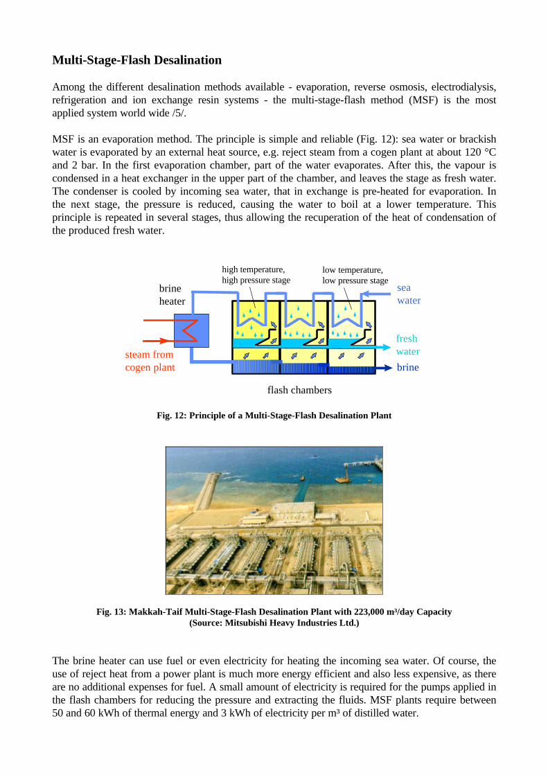
MSF is an evaporation method. The principle is simple and reliable (Fig. 12): sea water or brackishwater is evaporated by an external heat source, e.g. reject steam from a cogen plant at about 120 °Cand 2 bar. In the first evaporation chamber, part of the water evaporates. After this, the vapour iscondensed in a heat exchanger in the upper part of the chamber, and leaves the stage as fresh water.The condenser is cooled by incoming sea water, that in exchange is pre-heated for evaporation. Inthe next stage, the pressure is reduced, causing the water to boil at a lower temperature. Thisprinciple is repeated in several stages, thus allowing the recuperation of the heat of condensation ofthe produced fresh water.
seawater
freshwater
brinesteam fromcogen plant
brineheater
flash chambers
high temperature,high pressure stage
low temperature,low pressure stage
Fig. 12: Principle of a Multi-Stage-Flash Desalination Plant
Fig. 13: Makkah-Taif Multi-Stage-Flash Desalination Plant with 223,000 m³/day Capacity(Source: Mitsubishi Heavy Industries Ltd.)
The brine heater can use fuel or even electricity for heating the incoming sea water. Of course, theuse of reject heat from a power plant is much more energy efficient and also less expensive, as thereare no additional expenses for fuel. A small amount of electricity is required for the pumps applied inthe flash chambers for reducing the pressure and extracting the fluids. MSF plants require between50 and 60 kWh of thermal energy and 3 kWh of electricity per m³ of distilled water.

Sample Cogeneration System powered by Solar and Waste Energy
Figure 14 shows the simplified sketch of a complete solar and waste driven cogeneration system. Theplant produces 35 MW of electricity, 24 MW of cooling power and 8000 m³/day of desalted water. Itis fed by heat from a 110,000 m² solar collector field and from a waste incineration plant with aninput of about 300 - 400 tons/day. Fuel oil is used for backup firing.
Electricity
Steam
Cooling
Heat
SolarCollectorField
WasteIncinerationPlant
Multi-Stage-FlashDesalination
Water
VaporAbsorptionChiller
Cogen Plant
Fig. 14: Sketch of a cogeneration plant driven by solar energy and by energy from waste
A typical daily load curve for such a system is shown in Figure 15. The plant delivers 8 MW of baseload electricity, mainly provided by energy from the waste incineration plant, and peak electricityprovided by energy from the solar field. The reject heat from the back pressure steam cycle is usedaround the clock for MSF-desalination and - specially during the day - in a vapour absorption chiller(VAC) for district cooling. Only 16 % of the input energy is lost during the energy conversionprocess in the cogen plant.
0 2 4 6 8 10 12 14 16 18 20 22 240
20
40
60
80
100
120
Time (hours)
Po
wer
Dem
and
(M
W)
LossesMSFVACPower
Fig. 15: Typical daily energy output curve of the sample cogen plant. Only 16 % of the input heat is lost duringthe process. The plant delivers electric power as well as steam for a MSF-desalination plant and for a vapour
absorption chiller (VAC) for district cooling.

Only 10 % of the input energy comes from an oil fired backup boiler. The rest is provided by thesolar field (30 %) and by the waste incineration plant (60 %). While the solar field covers excellentlythe peaking load period during the day, the waste incineration plant provides base load energyaround the clock (Fig. 16).
0 2 4 6 8 10 12 14 16 18 20 22 240
20
40
60
80
100
120
Time (hours)
Po
wer
Su
pp
ly (
MW
)
FuelSolarWaste
Fig. 16: Typical daily thermal energy input curve of the sample cogen plant. 60 % of the input energy issupplied by the waste incineration plant, 30 % by the solar field and 10 % by the backup fuel oil.
Fuel10 %
Solar30 %
Parasitics3 %
ThermalLosses13 %Power
Demand33 %
Absorp.Chill.25 %
Desal.26 %
Useful Energy84 %
Total Energy Input 100 %
Waste60 %
Fig. 17:Typical daily energy balance ofthe solar and waste energy drivencogeneration system.
Figure 17 shows the daily energy balance of such a system. 84 % of the energy input, of which only10 % is derived from fossil fuel resources, is converted to useful energy. In comparison to aconventional supply of electricity, cooling, water and waste disposal by separate oil fired steam cyclepower plants, electric compression chillers, oil fired MSF plants and landfill respectively, pollution isreduced by more than 95 %.

Example of Finance
Energy efficiency and use of renewable energy sources always means high investments, because theconsumption of fuel resources is substituted by capital goods like the waste incineration plant and thesolar collectors. The energy resource itself is free of charge, but the investment usually leads to aconsiderable capital cost and debt service. In the sample power plant described before, the totalinvestment of 140 MUSD is split into 40 MUSD equity capital and a 100 MUSD loan (see alsoFig. 18). The loan is financed with a 3 % interest rate and a repayment period of 10 years.
27,3%21,0%
26,9%
5,0%8,8%
5,0%
5,9%
Waste Plant Solar Field Cogen Plant Absorption ChillersMSF Plant Engineering Contingencies
Fig. 18: Break down of investment of the sample solar and waste powered cogeneration plant(total investment 140 MUSD)
Costs Revenues0
5
10
15
20
25
Mill
ion
US
D /
year
WasteWaterCoolingElectricityReturn on EquityDebt ServiceFuelO&M
Revenues:Electricity 0.060 USD/kWhCooling 0.04 USD/kWhWater 1.7 USD/m³Waste 50 USD/ton
Cost Parameters:Interest Rate 3 %/aRepayment 10 yearsFuel Cost 10 USD/MWhLifetime 25 years
Fig. 19: Expected annual costs and revenues of the sample cogeneration plant
For the annual balance, revenues for the generation of power, cooling capacity and water areassumed to be in the order of 0.06 USD/kWh, 0.04 USD/kWh and 1.7 USD/m³, respectively. Forwaste disposal, a revenue of 50 USD/ton is assumed (Fig. 19).
Under the assumed financial parameters, equity investment returns within 5 years, the loan isreturned within a period of 10 years. Afterwards, the return on investment is particularly high, as thefuel expenditures - that usually are the main running cost in such projects - are very low. The averageinternal rate of return of the example project is 27 %/year.

SYNTHESIS - The Frame of Finance for Market Extension
The SYNTHESIS Programme was designed by DLR and partners to support and accelerate themarket extension of solar thermal power /6/. First class German firms participate in this programmeand support market development and concrete projects. SYNTHESIS offers a complete frame formarket extension, including project development, general contracting and operation of solar powersystems, insurance and re-insurance, loans and equity capital, and - if required - support for obtaininge.g. public funding like the World Bank's Global Environmental Facility or guaranties from theGerman Federal Government. A scheme of tradable credits from CO2-reduction is presentlydeveloped on a private basis as a complement to public funding (Fig. 20).
Fig. 20: The SYNTHESIS Frame for Market Extension and Project Development
All projects in the frame of SYNTHESIS are designed such that solar power becomes competitive toconventional power sources. First class partners from industry and finance guarantee professionalproject development, erection and operation of the power systems on IPP basis.
Requisites for project initiation in a potential host country are the following:
• land and infrastructure should be provided at low cost or preferably free• low tax and custom duties (because fuel consumption is substituted by capital goods)• power purchase agreement with a 25 year concession• corresponding agreements for water, cooling, fuel and waste if applicable• tariff adaptation to inflation• grid access at fair tariffs• bank guaranties on power and services payments
If the necessary infrastructure is available, 20 % to 40 % of the plants should be fabricated in therespective host country. Under those terms, solar power will become a new indigenous energyresource for many solar countries. In the first phase of SYNTHESIS that lasts until 2010, 7000 MWof solar power will be installed world wide in about 50 projects, basically for supplying local powerneeds. In the second phase, due to the expected cost reductions by mass production, standardisationand continuous research and development, the solar electricity cost will be low enough to start asolar power export scheme with high tension DC-grids.

Conclusions
Solar thermal power stations with parabolic trough concentrating collectors are mature andcommercially proven in more than a decade of utility operation. Not only electricity in the multi-megawatt capacity range, but also heat for industrial or municipal applications like district cooling orsea water desalination can be supplied by those plants. Being conventional steam cycles applied forpower generation or for the cogeneration of electricity and heat, they can be driven not only by solarenergy during the day, but also by heat from fuel, biomass or waste incineration, thus offering round-the-clock full power availability. Intelligent measures to improve energy efficiency and the use ofrenewable energy sources can lead to economically and ecologically attractive solutions formunicipal and industrial applications in the utility scale, as shown by the example of a cogenerationplant for electricity, district cooling and water desalination powered by solar and waste energy.
In the frame of the SYNTHESIS Programme, first class international firms have accepted thechallenge to foster the market extension of solar thermal power stations. First steps will rely onhighly efficient, hybrid plants with a relatively small solar share of 10 % to 30 %. The target is toachieve economic competitiveness for fully solar powered utility stations within the next decade.Based on this technology, many solar countries will be able to exploit their vast natural resource ofsolar radiation for industrial and municipal energy needs. The export of solar electricity to othercountries is a logic consequence of this development and will be one of the pillars of the nextcentury's world electricity market.
Literature
/1/ Kearney, D.W., Cohen, G.E.: Current Experiences with the SEGS Parabolic Trough Plants, inBecker, M., Böhmer, M. (Editors): Proceedings of the 8th International Symposium on SolarThermal Concentrating Technologies, C.F. Müller Verlag, Heidelberg, Germany, 1997
/2/ Cohen, G.F., Kearney, D.W., Price, H.W.: Performance History and future costs of parabolictrough solar electric systems, Journal of Physics IV, Vol. 9, 1999
/3/ MVV Energie AG: Nonrecyclable Waste Incineration with Advanced Flue-Gas Treatment -Mannheim's Waste-to-Energy Incineration Plant, MVV Energie AG, Mannheim, Germany,1999
/4/ Kalkum, B., Korenyi, Z., Schmitt, F.: Examining the feasibility of supplying heating andcooling services in a new Chinese economic zone, 3R International, Vol. 33, No. 3, 1994
/5/ Wangnick, K.: International Desalination Association - World Wide Desalting PlantsInventory, Report No. 13, 1994
/6/ Trieb, F.: Competitive solar thermal power stations until 2010 - The challenge of marketintroduction, Journal of Physics IV, Vol. 9, pp. 687 - 692, 1999