solar photovoltaic based electric power project (2x25...
TRANSCRIPT

Prepared by:
August 2006
Electrification of Village Gavar Gaon
Category Remote Plain Area (201 HH)
District : Raipur, Chhattisgarh
Solar Photovoltaic Based Electric Power Project (2x25 kW)
Alternate Hydro Energy CentreIndian Institute of TechnologyRoorkee-247 667
Govt. of India, New DelhiGovt. of India, New Delhi

Prepared by:
August 2006
Alternate Hydro Energy CentreIndian Institute of TechnologyRoorkee-247 667
Govt. of India, New DelhiGovt. of India, New Delhi
Electrification of Village Gavar Gaon
Category Remote Plain Area (201 HH)
District : Raipur, Chhattisgarh
Solar Photovoltaic Based Electric Power Project (2x25 kW)

AHEC/Model DPR/Plain 200 HH/SPV
FOREWORD (This Foreword is not part of the Model DPR) The Ministry of Non-Conventional Energy Sources, Government of India (MNES) have identified over 24,000 remote villages which are proposed to be electrified through small renewable energy sources e.g. Small Hydro Power, Biomass Gasification and Solar Photovoltaic Technology, so as to improve the well being of population living in the far flung isolated areas.
To make the Remote Village Electrification (RVE) programme successful, it is necessary that the planning, design, execution and operation and maintenance of RVE projects is efficient and reliable and also economical in the long run. MNES, vide letters number 13/5/2005 – 06 RVE dated 23.12.2005 and even number dated 09.03.2006 has asked the Alternate Hydro Energy Centre, IIT, Roorkee (AHEC) to prepare model detailed project reports (DPRs) for the following four categories :
1. Category “A – 1” Village with 40 households in the hilly area. 2. Category “A – 2” Village with 40 households in the plain area. 3. Category “B – 1” Village with 200 households in the hilly area. 4. Category “B – 2” Village with 200 households in the plain area.
The villages are to be selected from the States of Madhya Pradesh, West Bengal, Jharkhand and Uttaranchal to make the DPRs more versatile and practical so that these model DPRs can be used with slight site specific changes by even those users who may not have much technical expertise.
This Document has been prepared for RVE through Solar Photo Voltaic Electric Power Plant for the Category “B - 2” Village: Gavar Gaon (Block: Mainpur, Distt.: Raipur, State: Chhattisgarh) and also to serve as a Model Document recommended for use as a guide for RVE of similar category villages (including those ones having some variation in number of house holds) with plant and site specific modification. Any suggestions from institutions, organizations, users and interested individuals are welcome. Suggestions should be addressed to: Head, Alternate Hydro Energy Centre, Indian Institute of Technology, Roorkee – 247667, Uttaranchal, India. E-mail: [email protected] Fax: +91 – 1332 – 273517.

AHEC/Model DPR/Hilly 40 HH/SPV
EXECUTIVE SUMMARY With the rapid changing scenario of fast depleting conventional energy sources, the future of conventional electric power system is getting uncertain. This has led to world wide thrust on development and use of non-conventional energy sources for electric power generation & use. This coupled with almost no chances of extending the electric power grids to the remote villages and particularly those located deep in the forest due to problems associated with drawing power lines through it and their O & M, use of non-conventional energy sources remains the only alternative for providing reliable electricity to such remote villages. Gavar Gaon (Distt. Raipur, Chhattisgarh) is a tribal village in plains situated in the deep green forests. The habitants are poor. Only a few families own plots of agriculture land. The production of food grains from these plots of agriculture land is low and therefore, they also have to buy the required balance quantity of food grains from the market. Most of the village people are below poverty line. Some of them are jobless. The Solar Photo Voltaic based Electric Power Plant (SPV) proposed for this village will be helpful for:
i. Improving the living conditions of the village people. ii. Generating new opportunities for over all up-liftment. iii. Providing light for study and promote education amongst children promising them
better future. iv. Providing required drinking water facility in the village. v. Creating awareness about the renewable sources of energy and using them for
entrepreneurship like micro-cottage industries etc. thereby improving economic conditions.
vi. Saving Kerosine and forest wood presently being used for lighting. vii. Creating environmental awareness amongst the people and help control avoidable
destruction of the forest. The project is envisaged to be constructed in a period of 12 months from the date of contract agreement. The proposed period takes care of the adverse conditions e.g. monsoon season etc. There being almost no paying capacity of most of the villagers, a low one time contribution of Rs. 1000 per house hold has been proposed towards initial construction of the plant (which, though insignificant, will create a sense of belongingness thereby help make the scheme successful and send good message to others to follow suit) and a monthly payment of Rs. 50/- per month towards O&M (which they will be able to pay as they will have a monthly saving on cost of kerosene). The balance cost of O & M will have to be managed by the Nodal Agency. Source of funding for construction of plant & the system is proposed to be as:
i. Incentive subsidy by MNES : Rs.152.310 lacs. ii. One time contribution by villagers : Rs. 2.01 lacs. iii. Balance to be paid by Nodal Agency : Rs. 34.582 lacs.
The estimated cost of the proposed 50 kW electric power project works out to Rs. 188.902 lacs. The cost of generation works out to Rs 34.968 per kWh & Rs. 46.625 per kWh without subsidy at 80% and 60% LF respectively and Rs. 16.494 & Rs. 21.993 per kWh with subsidy at 80% & 60% LF respectively which is reasonable.
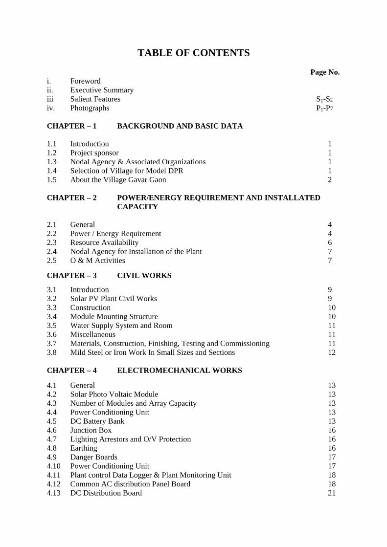
TABLE OF CONTENTS
Page No. i. Foreword ii. Executive Summary iii Salient Features S1-S2 iv. Photographs P1-P7 CHAPTER – 1 BACKGROUND AND BASIC DATA 1.1 Introduction 1 1.2 Project sponsor 1 1.3 Nodal Agency & Associated Organizations 1 1.4 Selection of Village for Model DPR 1 1.5 About the Village Gavar Gaon 2 CHAPTER – 2 POWER/ENERGY REQUIREMENT AND INSTALLATED
CAPACITY
2.1 General 4 2.2 Power / Energy Requirement 4 2.3 Resource Availability 6 2.4 Nodal Agency for Installation of the Plant 7 2.5 O & M Activities 7
CHAPTER – 3 CIVIL WORKS
3.1 Introduction 9 3.2 Solar PV Plant Civil Works 9 3.3 Construction 10 3.4 Module Mounting Structure 10 3.5 Water Supply System and Room 11 3.6 Miscellaneous 11 3.7 Materials, Construction, Finishing, Testing and Commissioning 11 3.8 Mild Steel or Iron Work In Small Sizes and Sections 12 CHAPTER – 4 ELECTROMECHANICAL WORKS 4.1 General 13 4.2 Solar Photo Voltaic Module 13 4.3 Number of Modules and Array Capacity 13 4.4 Power Conditioning Unit 13 4.5 DC Battery Bank 13 4.6 Junction Box 16 4.7 Lighting Arrestors and O/V Protection 16 4.8 Earthing 16 4.9 Danger Boards 17 4.10 Power Conditioning Unit 17 4.11 Plant control Data Logger & Plant Monitoring Unit 18 4.12 Common AC distribution Panel Board 18 4.13 DC Distribution Board 21

4.14 Cables 21 4.15 Solar Water distillation Plant 22 4.16 Engineering Drawings & Manuals 22 CHAPTER – 5 POWER DISTRIBUTION WORKS 5.1 Consumer Voltage Frequency and Variation and Power Factor 23 5.2 Provision of Load Limitors 23 5.3 Lightning Protection 23 5.4 Earthing 23 5.5 Distribution Sub-System 23 5.6 Cables 23 5.7 Type of Poles 24 5.8 Insulators 24 5.9 Stays 24 5.10 House Wiring 24 5.11 Maintenance Manual 25 5.12 Labels and Notices 25 5.13 Selection of Cable 25 CHAPTER – 6 TESTING & COMMISSIONING 6.1 Testing 26 6.2 Commissioning 26 6.3 Acceptance Tests at Site 26 CHAPTER – 7 PROJECT IMPLEMENTATION STRATEGY 7.1 General 27 7.2 Arrangement 27 CHAPTER – 8 CONSTRUCTION PROGRAMME 8.1 Pre-Construction Activities 28 8.2 Construction Activities 28 8.3 Contractual Period of O & M 28 CHAPTER – 9 ESTIMATED COST 9.1 Estimated Cost of the Plant and System 31 9.2 Funding 34 9.3 Financial Analysis 35 CHAPTER – 10 OPERATION AND MAINTENANCE OF PLANT 10.1 General 36 10.2 O&M for Initial 5 Years 36 10.3 Formation of Committee for Supervision Of O & M 37

CHAPTER – 11 ENVIRONMENTAL IMPECT AND BENEFITS 11.1 Environmental Impacts 38 11.2 Benefits 38 LIST OF PERSONNEL INVOLVED DRAWINGS: Drg. No.
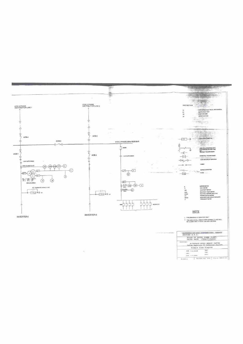
i. District Map of Chattisgarh and Raipur ii. Map of village Gavar Gaon C-338-1 iii. Solar Plant Building & Open Yard C-338-2 iv. Schematic Block Diagram of Solar PV Based Electric Power Plant E-338-1 v. Single line Diagram E-338-2

AHEC/Model DPR/Plains200/SPV
S-1
SALIENT FEATURES
1.1 GENERAL i. Name of the Project : SPV based Project, for Gavar Gaon Village ii. Location
a. Village : Gavar Gaon b. Block : Mainpur c. Tehsil : Gariaband d. District : Raipur e. State : Chhattisgarh
iii. Access a. Air : Raipur (Dhamtari Road–20 km from Raipur) a. Rail : Raipur (SECR) b. Road : 90 km from Raipur (on NH-43)
iii. Geographical Co-ordinates a. Latitude : Between 21 deg.27 min. North. b. Longitude : Between 82 deg 01 min East
iv. Climatic Conditions a. Annual Average Temperature : 35.32 0 C b. Annual Average Wind Speed : 4.62 m/s c. Annual Average Relative : 62.75%
humidity
d.. Period of Rainfall : June 20 to September 15.
v. Land for Project Construction : To be provided by the village / Forest Department.
vi. Location of proposed Plant Site : With in the village.
1.2 CIVIL STRUCTURES (Date given here are Tentative only)
Proposed Sizes:
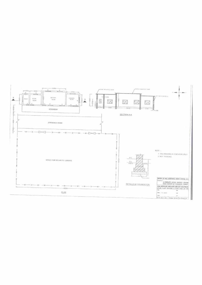
i. SPV Array : 60 m x 40 m ii. SPV Plant Building:
a. Battery Room : 15 m x 4 m x 4 m b. Control Room : 3.7 m x 3.4 m x 3.6 m c. Store Room : 3.4 m x 3.0 m x 3.6 m d. General Facilities : Drinking water facility, Toilets, Fencing, Gate, Sewerage system etc.
1.3 POWER EVACUATION AND DISTRIBUTION SYSTEM
Distribution System shall be made as per the site conditions and location of various house holds and other user points. i. No. of House Holds : 201 ii. L.T. Distribution Line
a. No. of Lines 2 : 415 kV, 3 - Phase, 50 Hz.
b. No. of Street Light Points : 40
AHEC/Model DPR/Plains200/SPV
S-2
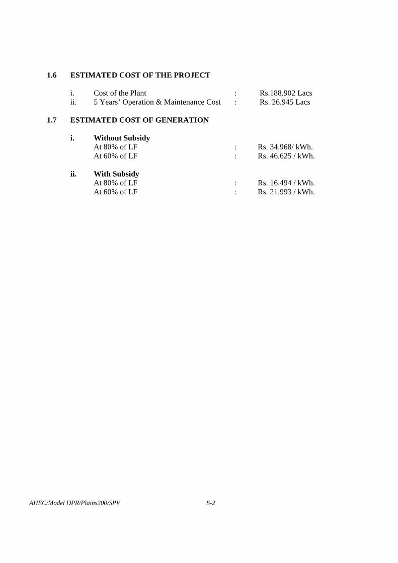
1.6 ESTIMATED COST OF THE PROJECT i. Cost of the Plant : Rs.188.902 Lacs ii. 5 Years’ Operation & Maintenance Cost : Rs. 26.945 Lacs
1.7 ESTIMATED COST OF GENERATION
i. Without Subsidy At 80% of LF : Rs. 34.968/ kWh. At 60% of LF : Rs. 46.625 / kWh.
ii. With Subsidy
At 80% of LF : Rs. 16.494 / kWh. At 60% of LF : Rs. 21.993 / kWh.

P-1
PHOTO - 3 : HAT BAZAR (VILLAGE MAP - ROUTE NO. 1)
PHOTO - 2 : STATUS OF RAWAD & RAMLILA GROUND(VILLAGE MAP-ROUTE NO. 2)
PHOTO - 4 : BAJRANGBALI TEMPLE (VILLAGE MAP-ROUTE NO. 3)
PHOTO - 1 : OLD HAT BAZAR & TENDU PATTASTORE AS VIEWED FROM ROUTE NO. -2

P-2
PHOTO - 6 : A VIEW OF DEEP FOREST FROM VILLAGESIDE ROUTE NO. 4
PHOTO - 5 : A VIEW OF VILLAGE HOUSES(VILLAGE MAP-ROUTE NO. 3)
PHOTO - 8 : GENERAL VIEW OF GAVAR GAON
PHOTO - 7 : ANGANWADI - A VIEW FROM ROUTE NO. 2

P-3
PHOTO - 10 : A VIEW OF CROSSING OF ROUTES NO. 3,4,5 & 2(ROUTE NO. 2 ON THE FRONT)
PHOTO - 11 : A VIEW OF VILLAGE ROUTE NO. 2TOWARDS ROUTE NO. 4
PHOTO - 9 : CROSSING OF ROUTES NO. 5,2,3 & 4AS VIEWED FROM ROUTES NO. 4 & 5
PHOTO - 12 : GENERAL VIEW OF VILLAGE GAVAR GAON.

P-4
PHOTO - 14 : A VIEW OF (VILLAGE MAP - GAI CHATTAANON THE RIGHT : ROUTE NO. 5)
PHOTO - 15 : A VIEW OF VILLAGE HOUSES(VILLAGE MAP - ROUTE NO. 7)
PHOTO - 16 : A VIEW OF VILLAGE HOUSES(VILLAGE MAP - ROUTE NO. 7)
PHOTO - 13 : A VIEW OF VILLAGE HOUSES
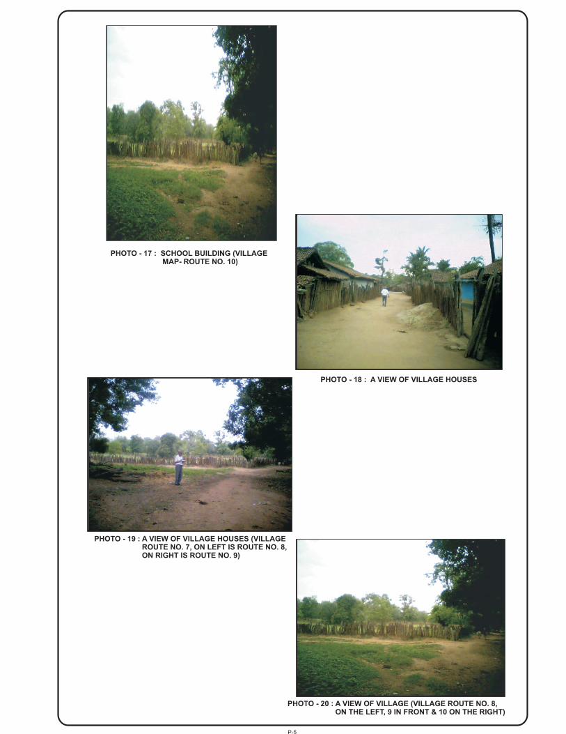
P-5
PHOTO - 18 : A VIEW OF VILLAGE HOUSES
PHOTO - 19 : A VIEW OF VILLAGE HOUSES (VILLAGEROUTE NO. 7, ON LEFT IS ROUTE NO. 8,ON RIGHT IS ROUTE NO. 9)
PHOTO - 17 : SCHOOL BUILDING (VILLAGEMAP- ROUTE NO. 10)
PHOTO - 20 : A VIEW OF VILLAGE (VILLAGE ROUTE NO. 8,ON THE LEFT, 9 IN FRONT & 10 ON THE RIGHT)
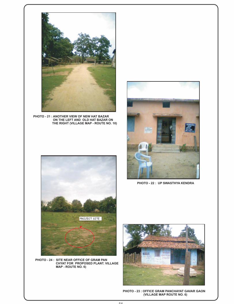
P-6
PHOTO - 22 : UP SWASTHYA KENDRA
PHOTO - 21 : ANOTHER VIEW OF NEW HAT BAZARON THE LEFT AND OLD HAT BAZAR ONTHE RIGHT (VILLAGE MAP - ROUTE NO. 10)
PHOTO - 24 : SITE NEAR OFFICE OF GRAM PANCHYAT FOR PROPOSED PLANT. VILLAGEMAP - ROUTE NO. 6)
PHOTO - 23 : OFFICE GRAM PANCHAYAT GAVAR GAON(VILLAGE MAP ROUTE NO. 6)
PROJECT SITE
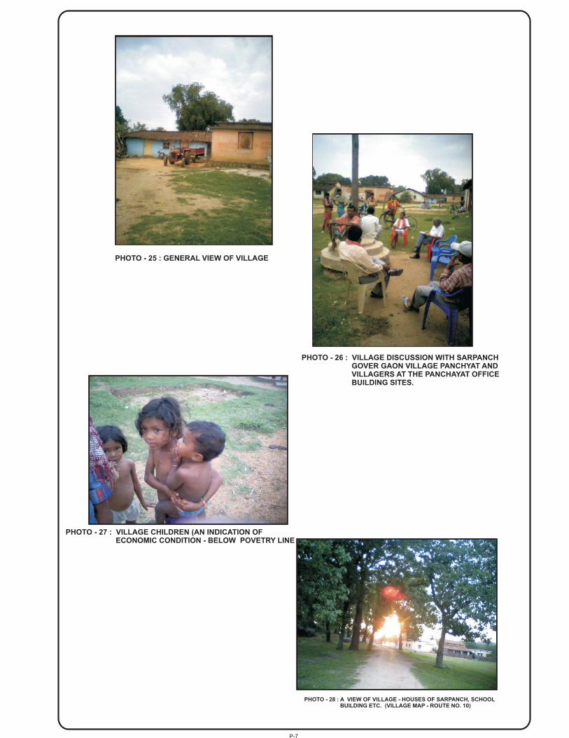
P-7
PHOTO - 27 : VILLAGE CHILDREN (AN INDICATION OFECONOMIC CONDITION - BELOW POVETRY LINE
PHOTO - 25 : GENERAL VIEW OF VILLAGE
PHOTO - 26 : VILLAGE DISCUSSION WITH SARPANCHGOVER GAON VILLAGE PANCHYAT ANDVILLAGERS AT THE PANCHAYAT OFFICEBUILDING SITES.
PHOTO - 28 : A VIEW OF VILLAGE - HOUSES OF SARPANCH, SCHOOLBUILDING ETC. (VILLAGE MAP - ROUTE NO. 10)

AHEC/Model DPR/Plains 200 HH/SPV
1
CHAPTER – 1
BACK GROUND AND BASIC DATA
1.1 INTRODUCTION
There is acute shortage of electric power generation in the country so much so that the areas already connected to the power grids are subjected to frequent power cuts. The available fuel resources being used for electricity generation are getting fast depleted. This problems and sensitivity coupled with problems in drawing the Electric Power lines through deep forest, the cost involved in extending the power grids and cost and problems in O & M of such line etc. make it almost impossible to make grid electricity reach the remote village Gavar Gaon (Distt. Raipur, Chhattisgarh).
The economic and social conditions of the inhabitants of Gavar Gaon are poor. Electricity being one of the basic infrastructural requirements for development and progress, the only hope in the above scenario is the use of renewable energy sources to generate and supply electricity to this remote village. In an effort towards this end, this project has been conceived for immediate implementation.
1.2 PROJECT SPONSOR
MNES, GOI has come up to subsidize the cost of RVE project to a large extent. The balance cost is to be met by the Nodal Agency and the people of the village.
1.3 NODAL AGENCY & ASSOCIATED ORGANIZATIONS
Chhattisgarh State Renewable Energy Development Agency (CREDA), Raipur has been assigned to carry out energy development work through non-conventional energy sources by the Government of Chhattisgarh. Discussions were held with the officers and staff of the CREDA, Village Panchayat etc. particularly:
I. Chattisgarh State Renewable Energy Development Authority 1. Sri Rajesh Trivedi, EE 2. Sri Rajiv Gyani, SDO
II. Village Panchayat and Others
1. Sri Farsu Ram Netam, Sarpanch, 2. Sri Hindu Ram Netam, Panch, 3. Sri Mendru Ram Netam, Panch, 4. Sri Sri Shomas Ram Mandavi, Panch, 5. Sri Birbal Singh Nayak, Swasthya Karmchari, 6. Sri Mehtar Ram Nadal, Forest Guard.
1.4 SELECTION OF VILLAGE FOR MODEL DPR
Tours were undertaken to various remote villages located in the Districts of Raipur, Bilaspur and Korba forest areas for selection of village(s) in co-ordination with CREDA, gathering information and data, interaction with the local people and the village level organizations e.g. Gram Panchayat, etc. and visual survey and assessment of various aspects related to the project to be undertaken. After detailed studies, remote village Gavar Gaon ( District of Raipur) located in the plains in the deep forest area has been selected for preparation of this Model Detailed Project Report.
1.5 ABOUT VILLAGE GAVAR GAON
1.5.1 Location Gavar Gaon is a remote village located in the plains in evergreen forest. The approach to the village is through a 8 km long Kachcha forest road taking off on the right from the town of Gariaband, which is situated on NH 43 at a distance of 82 km from Raipur (Fig. 1.1)

AHEC/Model DPR/Plains 200 HH/SPV
2
1.5.2 General Information and Basic Data General information gathered from documents, discussions with the officers and staff, from Sri Farsu Ram Netam, Sarpanch, Panchs, Upsarpanchs and the villagers is given below:
i. The Village Gavar Gaon is a tribal village (under Block – Mainpur, Tehsil – Gariaband, District – Raipur, Chhattisgarh) and under the Gram Panchayat Gavar Gaon.
ii. The Forest Cover Gavar Gaon is surrounded by ever green forest on all the sides.
iii. Population There are 201 households, some house holds having agriculture land, some landless with population of about 1200 (about 625 male and 575 female).
iv. Economic Status All the residents are Tribals (Adivasis), about 90% of them being below poverty line.
v. Level of Education The number of educated persons in the village is small. The number of children studying is reported to be as 153 in the primary school and 65 in the middle school.
vi. Profession It includes agriculture, collection of Tendu leaves for selling to Forest Department, collection of Mahua for various uses, collection of Achar for selling and casual labour in neighbouring towns.
vii. Domestic Animals Most of the families keep domestic animals (Cows, Buffalos, Oxen, Goats, Hens). Most of the animals are not getting required feed and therefore, are weak and milk production is low.
viii. Agriculture Production The agriculture production include Wheat, Paddy, Maize, Urd, Kodu, Kutki, Kulthi, Blhar,
Jwar, Sama, Samaria, Sarson, Tili, Ramtili, Arhar and Madia (a type of drink). The produce is not sufficient to meet their own requirement and some families have to buy food grains from market.
ix. Water Availability There are 8 wells and 2 ponds- one spread in an area of about 2 acres and the other in about 1.5 acres. The ground water is available at about 7m depth.
x. Animal fodder The requirement is met from the forest and from agriculture.
xi. Institutions There is 1 Middle school and 1 Primary School in the village. The teachers are reported to be coming from other places – doing daily up-down.
xii. Roads & Means of Transport The village is connected by means of 5 km long kachcha forest road to and single lane metalled road to ultimately leading to the town of trimbkeshwar (Block & Tehsil).
xiii. Forest Area Assigned to Bafen Vihir Gavar Gaon has been assigned some low-density forest area the Maharastra Forest
Department for their use. It has natural and unnatural forest both extending to about 1 km in N-S direction and 2 km in E-W direction.
xvi. Lighting The villagers get about 2 to 3 litres of Kerosine per month at subsidized rates, which is used by them for lighting for an hour or so per day. Since the quantity of Kerosine falls short of requirement, they also use fire wood, which they bring from the forest, for lighting purpose.
xiv. Use of Wood etc. for Cooking The villagers get Bamboos and Ballies (Logs) from the Forest Department and collect some
head loads of wood for own use in a year. The quantity of cow-dung (cakes) and agriculture
AHEC/Model DPR/Plains 200 HH/SPV
3
waste is low. Forest wood is also being used for lighting as the availability and affordability of Kerosine is limited.
xv. Forest Produce in the Assigned Forest Area The produce comprises Sagon, Haldu, Bans, Tinsa, Ladia, Tendu and Mahua. The villagers
get some income from collection of Tendu leaves which is paid for by the Forest Department.
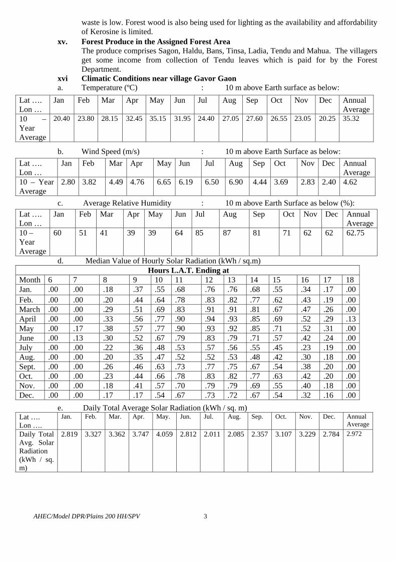
xvi Climatic Conditions near village Gavor Gaon a. Temperature (ºC) : 10 m above Earth surface as below:
Lat …. Lon …
Jan Feb Mar Apr May Jun Jul Aug Sep Oct Nov Dec Annual Average
10 – Year Average
20.40 23.80 28.15 32.45 35.15 31.95 24.40 27.05 27.60 26.55 23.05 20.25 35.32
b. Wind Speed (m/s) : 10 m above Earth Surface as below:
Lat …. Lon …
Jan Feb Mar Apr May Jun Jul Aug Sep Oct Nov Dec Annual Average
10 – Year Average
2.80 3.82 4.49 4.76 6.65 6.19 6.50 6.90 4.44 3.69 2.83 2.40 4.62
c. Average Relative Humidity : 10 m above Earth Surface as below (%):
Lat …. Lon …
Jan Feb Mar Apr May Jun Jul Aug Sep Oct Nov Dec Annual Average
10 – Year Average
60 51 41 39 39 64 85 87 81 71 62 62 62.75
d. Median Value of Hourly Solar Radiation (kWh / sq.m) Hours L.A.T. Ending at
Month 6 7 8 9 10 11 12 13 14 15 16 17 18 Jan. .00 .00 .18 .37 .55 .68 .76 .76 .68 .55 .34 .17 .00Feb. .00 .00 .20 .44 .64 .78 .83 .82 .77 .62 .43 .19 .00March .00 .00 .29 .51 .69 .83 .91 .91 .81 .67 .47 .26 .00April .00 .00 .33 .56 .77 .90 .94 .93 .85 .69 .52 .29 .13May .00 .17 .38 .57 .77 .90 .93 .92 .85 .71 .52 .31 .00June .00 .13 .30 .52 .67 .79 .83 .79 .71 .57 .42 .24 .00July .00 .00 .22 .36 .48 .53 .57 .56 .55 .45 .23 .19 .00Aug. .00 .00 .20 .35 .47 .52 .52 .53 .48 .42 .30 .18 .00Sept. .00 .00 .26 .46 .63 .73 .77 .75 .67 .54 .38 .20 .00Oct. .00 .00 .23 .44 .66 .78 .83 .82 .77 .63 .42 .20 .00Nov. .00 .00 .18 .41 .57 .70 .79 .79 .69 .55 .40 .18 .00Dec. .00 .00 .17 .17 .54 .67 .73 .72 .67 .54 .32 .16 .00
e. Daily Total Average Solar Radiation (kWh / sq. m) Lat …. Lon ….
Jan. Feb. Mar. Apr. May. Jun. Jul. Aug. Sep. Oct. Nov. Dec. Annual Average
Daily Total Avg. Solar Radiation (kWh / sq. m)
2.819 3.327 3.362 3.747 4.059 2.812 2.011 2.085 2.357 3.107 3.229 2.784 2.972

AHEC/Model DPR/Plains200 HH/SPV
4
CHAPTER – 2
POWER / ENERGY REQUIREMENT AND INSTALLED
CAPACITY 2.1 GENERAL 2.1.1 Vocation of Remote Electrification
The electrification of remote village is intended here to use of limited quantity of electricity to the isolated area not connected with electrical power grid.
2.1.2 The Type of Use of Electricity
The use of electric power is proposed for: i. Domestic Uses ii. Public Lighting iii. Drinking Water Pumping iv. Multi-purpose Uses v. Meet out future expansion/growth in the next 10 years’ period.
2.1.3 Use Requirement The use of electricity is proposed to be limited to:
i. 1 kWh of electricity per household per day (up to a period of 7 hours per day say, 3 hours in the morning and 4 hours in the evening).
ii. Public lighting up to 40 points @ 18 watts (CFL) per point for up to 4 hours in the evening.
iii. Drinking water pumping. iv. Multipurpose uses e.g. meeting out the irrigation needs, lighting of public
buildings - school & Anganwadi, lighting of community centre, needs of agro- based cottage industries, lighting of places of worship, battery charging, needs of shops, clinics etc. which may come up in later get motivated/educated on realization of benefits of electric power availability.
v. Future expansion: assumed as 20% during the period of 10 years. 2.2 POWER / ENERGY REQUIREMENT
The requirement has been worked out as per the consideration above and the criteria discussed below and summarized in Table:- 2.1 : Typical Power Supply Programme (Future Vision) shown in Fig.2.1. i. Domestic Uses
a. Connected load per H.H- 200 watts (assumed: 2 Nos. 11 W CFLs, 1 No. 60 W Fan, any other load up to 118 W)
b. Diversity factor:

AHEC/Model DPR/Plains200 HH/SPV
5
• CFL: 100% (some CFLs may fuse and some households may use more numbers).
• Other load: 200% (Diversity factor may be higher initially but Will decrease in due course (due to change in attitude and habits of the people – particularly the younger ones).
c. Actual load per HH. : 2x11 + 178/2 =111 Watts. d. Supply hours : 7/day (3 hrs.morning, 4 hrs.evening).
e. Total power needed for 201 H.H. : 111 x 201 = 22311W = 22.311 kW f. Energy consumption per H.H. / day: up to 111 x 7 Wh. = 777 Wh. or say, 0.80 kWh. g. Total energy consumption / day for 201 H.H = 0.80 x 201 kWh
= 160.80 kWh. ii. Public Lighting
It is proposed that public lighting may be only for 4 hours in the evening initially. The final operation and maintenance is conceived to be in the hands of the local body of the village when public lighting and other loads will be managed by them as per their choice, may be for more number of hours. a. No. of light points : Up to 40. b. Type of lighting : 18 Watts CFL. c. Lighting hours : 4 hours in the evening. d. Power required : Up to 18x40 = 720 Wor 0.72 kW. e. Energy consumption : Up to 0.72 x 4 hrs. or 2.88 kWh.
iii. Drinking Water Pumping
a. Water requirement per HH : Up to 180 liters (Assuming 30 liters /person and 6 persons / house hold).
b. Total water pumping required : 180 x 201 = 36180 litres = 36.18 cu m.
b. Pumping power needed (assuming pumping height of 50 m & pump efficiency as 60%:
9.81x(36.18 / 3600)x 50 x 0.60 = 2.9755 kW, Say, 5 HP or 3.736 kW. d. Pumping period : Assumed up to 1 hour. e. Energy consumption : up to 1 x 3.736 = 3.736 kWh.
iv. Multipurpose Uses
Depending on requirement and willingness of the people, the plant can be operated for the required number of hours between 9 a.m. to 5 p.m (for which plant capacity will have to be increased suitably). The power availability for multipurpose use will then be limited to about 40 kW only. Presently, power can be used for up to 12 kW only and energy consumption as 12 x 7 = 84 kWh.
AHEC/Model DPR/Plains200 HH/SPV
6
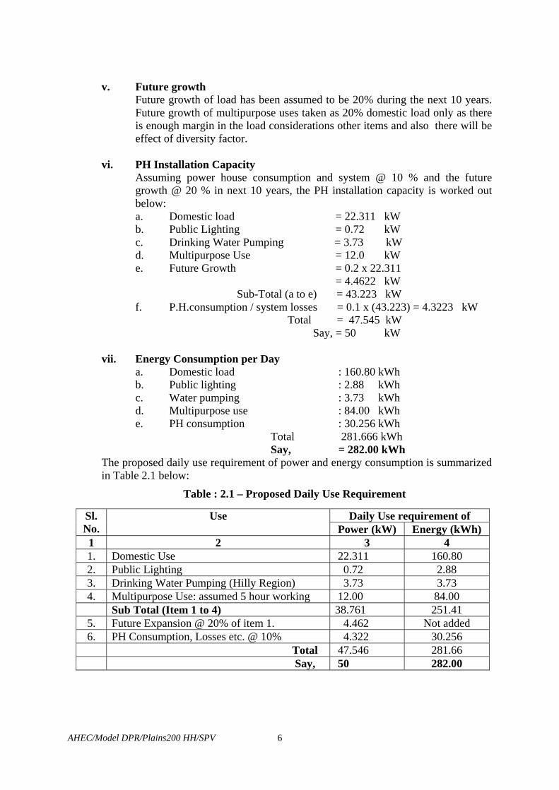
v. Future growth
Future growth of load has been assumed to be 20% during the next 10 years. Future growth of multipurpose uses taken as 20% domestic load only as there is enough margin in the load considerations other items and also there will be effect of diversity factor.
vi. PH Installation Capacity
Assuming power house consumption and system @ 10 % and the future growth @ 20 % in next 10 years, the PH installation capacity is worked out below: a. Domestic load = 22.311 kW b. Public Lighting = 0.72 kW c. Drinking Water Pumping = 3.73 kW d. Multipurpose Use = 12.0 kW e. Future Growth = 0.2 x 22.311
= 4.4622 kW Sub-Total (a to e) = 43.223 kW
f. P.H.consumption / system losses = 0.1 x (43.223) = 4.3223 kW Total = 47.545 kW
Say, = 50 kW
vii. Energy Consumption per Day a. Domestic load : 160.80 kWh b. Public lighting : 2.88 kWh c. Water pumping : 3.73 kWh d. Multipurpose use : 84.00 kWh e. PH consumption : 30.256 kWh Total 281.666 kWh Say, = 282.00 kWh
The proposed daily use requirement of power and energy consumption is summarized in Table 2.1 below:
Table : 2.1 – Proposed Daily Use Requirement
Daily Use requirement of Sl. No.
Use Power (kW) Energy (kWh)
1 2 3 4 1. Domestic Use 22.311 160.80 2. Public Lighting 0.72 2.88 3. Drinking Water Pumping (Hilly Region) 3.73 3.73 4. Multipurpose Use: assumed 5 hour working 12.00 84.00 Sub Total (Item 1 to 4) 38.761 251.41
5. Future Expansion @ 20% of item 1. 4.462 Not added 6. PH Consumption, Losses etc. @ 10% 4.322 30.256
Total 47.546 281.66 Say, 50 282.00
AHEC/Model DPR/Plains200 HH/SPV
7
2.3 RESOURCE AVAILABILITY 2.3.1 Access
i. It should have a simple workable access or possibility of making such access at low cost.
ii. The area should be safe for the people to work at site. iii. There should be availability of suitable raw material for construction of civil
works.
2.3.2 Operation and Maintenance i. Availability of local persons/persons from nearby area having reasonable
reading and writing skills, suitable intellectual capacity and willingness to work as operator/ maintenance staff.
ii. Required facility to provide an on situ training to the above persons. iii. Required tools and plants, gadgets, safety equipment, etc. as required for
maintaining the micro-hydro plant and distribution system. iv Availability of spare parts for successful operation of plant for 10 years
period. 2.3.3 Availability of Monetary Resource
The scheme is to be funded: i. Partially by the MNES. ii. By initial lump sum contribution by the village people. iii. The rest by the Nodal Agency.
2.4 NODAL AGENCY FOR INSTALLTION OF THE PLANT AND O&M
Supervision, Planning, Designing, Processing the purchase case, Placement of order, Supervising construction, Liaison etc. is to be carried out by the Nodal Agency i.e. the Chhattisgarh Renewable Energy Development Authority, Raipur, (Chhattisgarh). The Nodal Agency is also proposed to co-ordinate and arrange for O&M of the plant and regular supervision ( Chapter-10).
2.5 O & M ACTIVITIES
The management, operation and maintenance of the plant (including distribution system) is to be carried out by the contractor for initial 5 (Five) years period and thereafter by the Village Panchayat, Gavar Gaon.

INDEXDL-
DW- Drinking water pumpingMU-
BC- DC Battery ChargingAN
PC- & SL
FG - Future Load Growth
0Note:
Fig. 2.1:-
40
Cat
egor
y -'B
' (20
0 H
ouse
Hol
ds)
41 9 10 11
To enable Poweravailability during morenumber of hours infuture as shown in thisfigure, the installedCapacity will have to besuitably increased.
2 3 181716
30
25
12
Pow
er R
equi
rem
ent (
kW)
35
20
10
5
45
15
196 13 14 15
Day Time (hr)
Power houseConsumption & Systemlosses
Domestic Load Lighting,Fan, Radio, T.V. etc.
Multipurpose uses(cottage industries,Agricultural value-adding industries, Loadsof community centre,School, Clinics, Shopsetc.)
Agricultural Needs eg.Water Pumping forIrrigation
237 85 20
50
8
Typical Power Supply Programme (Future Vision)-Timings are Adjustable on Seasonal Basis andother Requirements, if any.
2421 22
DW
Multipurpose Uses (MU) (Future Vision)
Domestic Load (DL)Domestic Load (DL)
Power House Consumption & System Losses (PC & SL)
Future Load Growth (FG)

AHEC/Model DPR/Plains200 HH/SPV
9
CHAPTER - 3
CIVIL WORKS 3.1 INTRODUCTION
The civil structures related to the Solar Photo Voltaic Power Plant (SPV) are proposed to comprise: i. SPV Array Yard. ii. SPV Plant Building comprising mainly:
a. Battery Room. b. Control Room. c. Store Room. d. General Facilities.
iii. Water Supply System and Room iv. Sewerage system. v. Fencing, Gate etc.
3.2 SOLAR PV PLANT CIVIL WORKS
The main structures are described below. Any other structure required is also to be made. The dimensions stated are approximate and tentative only.
3.2.1 SPV Array Yard A SPV Array Yard of approximate size 60 m x 40 m may be required. It is proposed to be located in front of the SPV building facing south.
3.2.2 SPV Plant Building
i. Battery Room. A Battery room of size 15.0 m x 4.0 m x 4.0 m approximately may be required to house the DC Batteries. This room may be constructed with 250 mm thick stone or brick walls and RCC roofing. (Drg. No. AHEC/C-347-2)
ii. Control Room The control room may have a size of 3.7 m x 3.4 m x 3.6 m and located by the side of the Battery Room. It may be constructed with 250 mm thick brick walls and RCC roofing. The battery charger is to be housed in the control room. (Drg. No. AHEC/C-347-2)
iii. Store Room Store Room may have a size of 3.4 m x 3.0 m x 3.6 m and may be constructed with 250 mm thick brick walls and RCC roofing. (Drg. No. AHEC/C-347-2)
iv. General Facilities Drinking water facility, toilets, etc may be provided.

AHEC/Model DPR/Plains200 HH/SPV
10
3.2.3 Water Supply System Room and Storage Tank A room of size 3 m x 2.5 m x 3.6 m made of 250 mm thick stone / brick walls and covered with CGI sheets may be constructed to house the motor, controls etc and lifting arrangement at the top.
3.3 CONSTRUCTION i. Adequate arrangement for proper ventilation shall be provided. It shall include
exhaust fans and smoke exhaust pipe located in a manner to ensure removal of smoke in direction away from the building.
ii. The control room shall be made of good quality mosaic with best quality white cement and marble chips.
iii. Inside brick wall shall be plastered and white wash distempered. iv. Windows/ventilators shall be fixed to ensure natural lighting inside the
buildings. v. Proper equipment fitting facility shall be provided. vi. Proper lighting arrangement shall be made both inside and outside the
buildings / SPV Array Yard and approach road.
The construction is to be done as per the Approved drawings. The structural design shall be done based on soil test, stability and safety etc. The construction is to be carried out as per the National Building Code of India, unless otherwise approved. Any other arrangement required as per site condition shall be made to ensure proper functioning of the plant and the system.
3.4 MODULE MOUNTING STRUCTURE 3.4.1 Design of Structure
i. The structure shall be designed for simple mechanical and electrical installation and therefore, it shall support SPV modules shall be supported at a given orientation, absorb and transfer the mechanical loads to the ground properly.
ii. There shall be no requirement of welding or complex machinery shall not be required at site.
iii. The structure shall be designed to allow easy replacement of any module. iv. Each structure shall have provision for tilt angle (to the horizontal) mounting
with. Provision shall be made for tilting from 5 to 35 degrees in steps of 5 degree in order to get maximum output from the SPV panel.
v. Appropriate size stainless steel nuts & bolts shall be used.
3.4.2 The Structure Foundation The legs of the structures made with hot dip GI angles will be fixed and grouted in the RCC foundation columns made with 1:2:4 cement concrete. The minimum ground clearance from the lowest part of any module shall be 500mm. Due consideration will be given to weight of module assembly while making foundation designs. The structure should be capable of withstanding wind speed of 150 km per hour after grouting and installation. Necessary excavation, concreting, back filling, shoring & shuttering etc shall be carried out.

AHEC/Model DPR/Plains200 HH/SPV
11
3.4.3 Material to be Used The made of Hot dip galvanized MS angles of size not less than 35mm X 35mm X 5 mm shall be used to make the array structure size. The minimum thickness of galvanization shall be not less than 80 microns. All nuts & bolts shall be made of very good quality of stainless steel. The minimum ground clearance of the lowest part of the module structure shall be 500 mm.
3.5 WATER SUPPLY SYSTEM AND ROOM 3.5.1 Setting up of Water Supply System
i. Installation of a 5 HP submersible type motor-pump unit, the motor being of Siemens /NGEF / Cromton / Jyoti / Kirloskar make operable on 230 V, 50 Hz, 0.8 PF AC supply.
ii. Boring and installation of tube well. iii. Water piping system including bends, sockets, valves, clamps, civil works etc. iv. Room for the above system.
3.5.2 Boring etc. Boring of tube well up to required depth and of required diameter by water jet system through any type of soil strata and including scaffolding, lowering of pipes, strainers, blind pipes including bucket washing, T&P etc.
3.5.3 Storage Tank
Making a 5000 litres PVC water storage tank of Sintex /Palton or equivalent Approved make to be installed on the roof of the SPV building.
3.6 MISCELLANEOUS WORKS
3.6.1 Gate The main gate is proposed to be 4 m (wide) x 1.80 m (high) comprising 2 panels made of MS angle frame and rods with guide Track etc. supported on 2 numbers 400 mm x 400 mm RCC pillars on both sides.
3.6.2 Fencing
Pre-cast RCC posts, 2 m high with 0.3 m bend at the top, is to be erected and chain link fencing (50 mm x 50 mm x 8 SWG size) fixed with the RCC posts by means of galvanized clips to a grid of horizontal strands of galvanized high tensile spring 12 SWG steel wire.
3.6.3 Approach Road Suitable approach road shall be provided for the required services.
3.6.4 Environmental Provisions Necessary provisions are to be made as per the requirement of environmental rules and regulations in force.
3.7 MATERIALS, CONSTRUCTION, FINISHING, TESTING AND
COMMISSIONING
These are recommended to be as per the relevant Indian Standards and the construction etc. in accordance with drawings to be approved by the Nodal Agency.
AHEC/Model DPR/Plains200 HH/SPV
12
3.8 MILD STEEL OR IRON WORK IN SMALL SIZES AND SECTIONS 3.8.1 Materials
The materials to be used, fabrication and construction method, supplying and fixing mild steel or iron work in small sizes and sections such as holding down bolts, holdfasts, tie rods, gratings etc. should be as per the relevant Indian Standards.
3.8.2 Painting Steel work is to be thoroughly cleaned of rust, loose scales, dust etc. as per latest edition of IS: 1477-part-I and given one coat of red oxide paint conforming to IS: 2074 applied as per IS: 1477-part-II. Over the surface inaccessible after placing in position, two coats of red oxide paint should be applied.

AHEC/Model DPR/Plains200 HH/SPV
13
CHAPTER – 4
POWER GENERATION EQUIPMENT AND SYSTEM 4.1 GENERAL
The power generation equipment and system is proposed to comprise mainly: i. Solar Photo Voltaic Module. ii. Power Conditioning Unit. iii. Distribution Panel. iv. Monitoring & Data Acquisition system. v. Lightning & Over Voltage Protection. vi. DC Batteries. vii. Cables. viii. Fire Fighting Equipment. ix. Miscellaneous Equipment.
4.2 SOLAR PHTO VOLTAIC MODULES
Mono / Poly Crystalline Silicon Modules conforming to IEC 61215 or IEE 1662 or equivalent International Standards having an efficiency of not less than 13 % and out put ranging from 75 watt to 120 watts are proposed to be used. The Solar Photo Voltaic modules may have following ratings: i. Power Out put : Min. 75 Watts (under STC) ii. Open Circuit Voltage : Not less than 21 V (under STC) iii. High Voltage Withstand Insulation Level : 3 kV D.C. for 1 minute. iv. Array Capacity : 87 kWp or so.
4.3 NUMBER OF MODULES AND ARRAY CAPACITY
Number of modules may range from about 1160 (for 75 W Module) to 730 (for 120 W Module) to give an output of 87 kWp.or so, as required.
4.4 POWER CONDITIONING UNIT Power conditioning unit shall comprise 240 V DC input, and 415 V AC, 3- Phase, 50
Hz , pure Sine Wave out put inverter (rating: 75 kVA) with suitable 100 kW charge controller.
4.5 DC BATTERY BANK
Rechargeable Battery Bank is proposed to be provided as described below:
i. The DC Batteries shall consist of required number 12 V deep-discharge flooded lead acid positive tubular plate and pasted negative plate type storage cells, suitably interconnected to obtain DC system voltage of 240 V. More than three Parallel connections of storage cells shall not be used.

AHEC/Model DPR/Plains200 HH/SPV
14
ii. The cells shall be capable of withstanding deep discharges and frequent cycling with long maintenance intervals. The cell should have high Ah efficiency. Automotive or car batteries shall not be used.
iii. The nominal voltage of the Battery Bank shall be 240 V and the capacity of 3000 AH at 10 hour discharge rate (C/10).
iv. The self-discharge rate of the battery bank or individual cell shall not exceed 4 (Four) percent (%) per month under ideal conditions. The cycle life of the battery shall not be less than 1500 charge-discharge cycles between the fully charged state and the permitted maximum DOD; at a rate of C/10.
v. The Cells shall have ceramic vent plugs and include required number of corrosion-resistant inter-cell connectors, nuts, bolts, petroleum jelly, hydrometer and all other necessary accessories.
vi. The electrolyte volume shall be sufficient to allow topping at least twice a year, for continuous operation in the PV system.
vii. The cells shall be supplied in dry charged condition and complete with all required chemicals/electrolyte packed in separate containers (with 10% extra quantity shall be provided).
viii. Suitable number of corrosion-resistant and acid-proof storage racks shall be supplied to accommodate the cells. The rack design shall ensure that minimum space is occupied, without obstructing the maintenance requirements.
ix. Battery rack could be of matured treated Sal wood duly painted. Placement of battery shall be done in a manner that maintenance of the
battery could be carried out easily. x. Non-reactive acid proof mat should be provided to cover the entire floor
space of the battery room. xi. Literature, Manual, Drawings, etc shall be provided for guidance and help
proper O&M, particularly giving following information also:
a. Rated voltage and ampere- hour capacity of each storage cell at C/10 discharge rate;
b. Permitted maximum DOD; c. Self-discharge rate; d. Cycle life of the storage cell and the anticipated life (number of
years) of the battery bank; e. Total number of storage cells in use; f. Instructions on first time charging, including specifications of the
required battery charger; g. Details on cell interconnections, if any, and h. Safety procedures.
The battery components and rating are given in Table - 4.1 (Annexure- 4 /1).

AHEC/Model DPR/Plains200 HH/SPV
15
4.5.2 Tools Kit
Necessary tools kit shall be provided along with each battery bank for any immediate maintenance requirements. These include, but not limited to : i. A Thermometer ii. Cell Tester, Hydrometer, Acid and Distilled water pouring container of
required size, Battery connecting leads, Gloves, Gum boots, petroleum jelly are required to be supplied with each Battery Bank.
4.6 JUNCTION BOXES
i. The junction boxes shall be dust and water proof and made of FRP or MS
(CRCA) as per Indian Standards. The terminals will be connected to copper lugs or bus bar of proper sizes.
ii. These will have suitable cable entry points fitted with cables glands. iii. Suitable markings shall be provided on the lugs or bus bar for easy
identification and cable ferrules will be fitted at the cable termination points for identification.
iv. Each main junction box shall be fitted with appropriate rating blocking diodes. iv. The junction boxes shall have arrangement for:
a. Combine groups of modules into independent charging sub-arrays that will be wired into the controller.
b. Provide arrangement suitable rating of fuses for each string. c. Provide a test point for each sub-group for quick fault location. d. The rating of junction boxes shall be suitable with adequate safety
factor to inter connect the Solar PV array. 4.7 LIGHTNING ARRESTER (LA) AND OVER VOLTAGE (O/V) PROTECTION
i. The SPV power plant shall be provided with LA and O/V protection. ii. The LA is shall be made of 20 mm diameter and 3.75 m long GI pipe on the
basis of the necessary meteorological data of the locations for the project. iii. Necessary foundation for holding the LA is shall be arranged keeping in view
the wind speed of the site and flexibility. iv. Each LA shall be earthed through suitable size earth bus bar with earth pits.
The earthing-pit shall be made as per IS 3043.
4.8 EARTHING i. Each array structure of the PV array shall be properly grounded. ii. Masts should be provided inside the array field. iii. Provision shall be made for shorting and grounding of the PV array at the time
of maintenance work. iv. All metal casing/shielding of the plant shall be thoroughly grounded in
accordance with Indian Electricity Act/IE Rules as amended up to date. Earth resistance shall be tested and maintained to 0.5 Ohms.
v. The earthing-pit shall be made as per IS 3043.

AHEC/Model DPR/Plains200 HH/SPV
16
4.9 DANGER BOARDS
Danger Boards shall be provided in Hindi, English and local language as and where necessary as per IE Act/IE Rules.
4.10 POWER CONDITIONING UNIT (PCU)
4.10.1 Inverter 4.10.2
i. Inverter(s) shall: a. be of extremely high quality having high efficiency & microprocessor
controlled Solar Mains Diesel (SMD) type and be capable of running in individual and parallel mode.
b. be capable of monitoring its own parameters. c. shall have the feasibility by which inverter capability for supplying
load, can be set at any pre determined load point by means of software. Beyond this load, the inverter should trip. The set points can also be remotely altered (set). The inverter(s) shall be so designed to be compatible with the Charge Controllers and distribution panel.
d. be reliable and efficient solid-state devices (such as IGBT’s) for DC-to-DC energy conversion.
e. be designed for continuous, reliable and stable power supply for the specified loads.
g. have high DC to AC conversion efficiency from 25 percent load to the full rated load. A load verses efficiency curve shall be provided.
h. have a high overload capability. A minimum of 150 percent of full rated output for 30 seconds and be able to maintain the rated voltage and frequency during over load conditions.
i. inverter output power factor in a range so as to supply or sink re-active power, as required.
j. automatic re-start facility after overload triggered shut down, once . the load retains its set value. k. have both the AC and the DC lines suitable fuses and contactors on to
allow safe start Up and Shut down of the system. Fuses used in the battery (DC) circuit shall be DC rated.
l. be capable of operating in parallel with similar inverters.
ii. The inverter shall be: a. Three-phase solid-state type and the output wave shape of the inverter
shall be sinusoidal. b. Required to running on the principle of the load-sharing basis. c. The having efficiency of more than 92% at full load.
The specifications are given in Table – 4.2 (Annexure – 4 / 2). 4.10.2 Spare Parts
Required spare parts and control cards are proposed be provided for 5 years O&M period as per the recommendations of the manufacturer. Each solid-state device shall be protected to ensure long life of the inverter as well as its smooth functioning.
AHEC/Model DPR/Plains200 HH/SPV
17
4.11 PLANT CONTROL, DATA LOGGER & PLANT MONITORING UNIT This unit shall be suitable for the following :
i. Controlling of the entire power system through a centralized station. ii. Measurement and / or recording of energy parameters. iii. Data logger or energy meter to record the energy data at a pre-determined
interval basis. iv. Measurement & continuous acquisition of ambient air temperature, wind
speed, solar radiation, PV module temperature, battery voltage and current during charging & discharging period, battery temperature, inverter output voltage, current and output frequency.
v. Operating state monitoring and failure indication. vi. Representing and monitoring data in both the graphics and tabulation mode.
vii. Controlling & monitoring the entire power system through remote terminal, as well as from a local terminal should be possible.
Necessary PCs with color monitors, modems, hardwires & software are recommended to be provided along with Plant Control, data logger & plant monitoring unit. Both the software and hardware required for interfacing the plant including the CPUs with color monitors, modems are to be provided.
4.12 COMMON AC DISTRIBUTION PANEL BOARD
i. A Distribution Panel Board (DPB) shall control the AC power from inverter to four feeders through switches.
ii. AC DPB shall have the arrangement for measuring all electrical quantities such as Voltage, Current of different feeder line & energy supplied to the different feeder.
iii. AC DPB shall have enclosure to protect from dust, vermin proof & adequate cooling arrangement. The bus-bars are to be made of copper of desired size. Design & Drawing is to be submitted to the purchaser before installation by obtaining necessary approvals.
4.13 DC DISTRIBUTION BOARD
DC distribution board shall consist of suitable metal casing with provision of incoming & out going cables. Each incoming & outgoing feeder must be provided with MCB of appropriate capacity. Arrangement for indications shall be made in the switchboard to identify status of the switchboard.
4.14 CABLES
All cables should be as per IS Standard and should be as per requirement.

AHEC/Model DPR/Plains200 HH/SPV
18
4.14.1 Cabling in the Array Field and Control Room
Cabling in the array field shall be carried out as per IE Rules, this include the size & type of the cable, the cable layout, depth of the trench, covering the cables, etc. Cabling inside control room should be in cable trench duly covered with RCC slabs. Size of cables & wires required are to be provided before commencement of work. Un-armored and armored cable as and where necessary shall be used. Cables shall be laid in GI pipes of suitable size in open trench as required. Cables shall be laid in the ground at a depth of 1m from the ground level along the approved route with necessary brick and GI pipe protection. Whenever the cable crosses the roads, drains, water sewage pipes or entering / leaving the buildings the cable shall be laid in Class-B GI pipe of suitable size.
4.14.2 Wires All wires should be as per IS and should be of appropriate grade as per requirement. Only copper wires of suitable size and of reputed make shall have to be used.
4.14.3 Cable Glands All connections are to be made through suitable cable glands/lug/terminals; crimped properly & with use of Cable Glands.
4.14.4 Cable Marking All cable/wires are to be marked with proper manner by good quality ferule or by other means so that the cable can be easily identified.
4.15 SOLAR WATER DISTILLATION PLANTS
Approved quality Solar Water Distillation Plant of capacity 3 to 4 liters per day is to be installed on suitable GI structure. If required the contractor can contact Solar Energy Centre for fabricating Solar Water Distillation Plant. At least two nos. plastic pots and one funnel are to be supplied along with each Distillation Plant.
4.16 ENGINEERING DRAWING & MANUALS
All relevant engineering drawings, electrical drawings, civil drawings and other drawings in respect of installation of power plant, all relevant documents along with installation and operation & maintenance manuals are to be supplied.

AHEC/Model DPR/Plains200 HH/SPV
19
Annexure – 4 / 1
Table - 4.1: Battery Components and Rating
Sl. No. Item Components / Rating
1 2 3
1. Container Polypropylene Co-polymer / hard rubber with carrying handle.
2. Cover Protective cover of polypropylenes against dirt & possible short
circuit.
3. Terminals Made of lead alloy suitable for bolted connection. The terminals
should be greased with petroleum gel.
4. Electrolyte Battery grade Sulphuric Acid
5. Self Discharge Less than 4% per month at 300 C.
6. Life Expectancy 1500 cycle duty at 270 C at 80% depth of discharge.
7. Nominal Voltage 2 Volt.
8. Type As approved by Railways or CECRI or ERTL or ETDC and as per
relevant standards for batteries for referred use.
9. Service Life Should perform satisfactorily for a minimum period of 6 year
under operating conditions as mentioned.

AHEC/Model DPR/Plains200 HH/SPV
20
Annexure – 4/2 Table – 4.2: Specifications
Sl. No.
Item Specifications
1 2 3 1. PV CHARGE CONTROLLER
Switching elements IGBT Type of Charger PWM Nominal Rating 240 V, 100 kW Control Microprocessor based PV Input 200V to 400V DC from PV Array (20 in series)
i. ii. iii. iv. v. vi.
Output Voltage Suitable for charging 240V nominal Battery Bank
vii. Charging Current 300A from PV viii.
Protections Deep Discharge (included in Inverter) Input Surge Voltage Battery high charge current Battery over voltage Battery reverse Polarity Solar Array reverse Polarity
ix. Indications Mains ON Boost Mode Enabled High Battery Temperature Fault High Battery Voltage Fault Low Battery voltage High Battery Charge current fault Heat sink over temperature fault Battery breaker opened/tripped Input Over/Under Voltage (for AC operation)
x. MIMIC Panel Indicates power activity and operation of the Charge Controller/Battery Charger
xi Dielectric Strength 1.1 kV between Input/Output & ground with EMI protections
xii. Cooling Forced, with temperature sensitive fan operation

AHEC/Model DPR/Plains200 HH/SPV
21
1 2 3
2. INVERTER 75 kVA i.
General Features a. High efficiency microprocessor controlled design, suitable for stand alone
operation b. Parallel synchronized operation possible of the same configuration, Each
inverter can monitor its own parameters c. Completely compatible with Charge Controller and Distribution Panel. d. Suitable for continuous, reliable operation, High overload capacity. e. Manual restart after any tripping due to fault. This is a safety requirement.
ii. Input DC Voltage 240V nominal iii. Output Voltage 400V- 415V nominal, 50 Hz, 3 phase, 4 wire iv. Waveform Sine wave, <3% THD v. Switching Elements IGBT vi.
Voltage Regulation +/- 1% against input voltage and load regulation for input voltage variation from 214V to 330 V, 0 to 100% load
vii. Frequency 50Hz +/- 0.5 Hz viii. Output Power 75 kVA ix.
Efficiency More than 92% at 100% load, at the rated input DC voltage
x.
Parallel Operation 2-Inverters can be operated in synchronization with load sharing capability if required at any time
xi. No load power consumption Less than 2.5% of total output rating xii. Overload capacity 150% for 30 sec, Output voltage may drop by
about 5% maximum. Frequency is maintained. xiii.
Step Load Recovery Less than 5 Sec. from 0 to 100% load, with a transient variation not more than 15% of nominal voltage
xiv.
Dielectric Strength 1.1 kV between Input/Output & ground and 1.5 kV between input and output with EMI protections removed
xv. Short Circuit Protection Circuit Breaker and electronic control xvi. xvii
Battery Low Voltage Auto shut down at 214V and starting at 230V, manual reset, software settable
xviii. Output Low / High Voltage
Auto shut down when +/- 10% of Nominal output voltage is exceeded, Software settable. Manual reset
xix High Battery Voltage Auto shutdown, Software settable, manual reset xx. AC Reverse Power Auto shutdown manual reset xxi. AC Over Current Auto shutdown, Software settable, manual reset xxii. Instrumentation LCD display panel xxiii. Status Indications Control Supply OK (Green)
PCU On line (Green) System Fault (Red – flashing)
AHEC/Model DPR/Plains200 HH/SPV
22
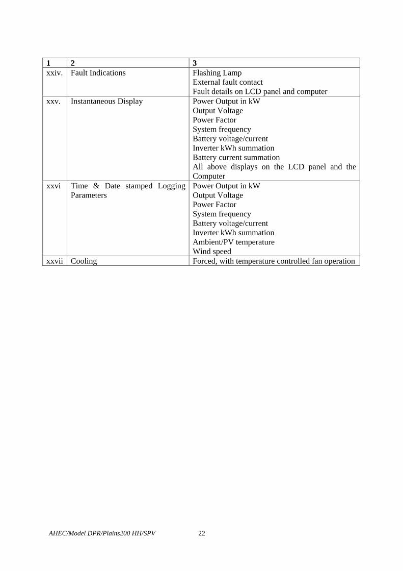
1 2 3 xxiv. Fault Indications Flashing Lamp
External fault contact Fault details on LCD panel and computer
xxv. Instantaneous Display Power Output in kW Output Voltage Power Factor System frequency Battery voltage/current Inverter kWh summation Battery current summation All above displays on the LCD panel and the Computer
xxvi Time & Date stamped Logging Parameters
Power Output in kW Output Voltage Power Factor System frequency Battery voltage/current Inverter kWh summation Ambient/PV temperature Wind speed
xxvii Cooling Forced, with temperature controlled fan operation

AHEC/Model DPR/Plains200 HH/SPV
23
CHAPTER - 5
POWER EVACUATION AND DISTRIBUTION SYSTEM 5.1 CONSUMER VOLTAGE, FREQUENCY AND VARIATION
The consumer voltage shall be 415 V, 50 Hz and variation of voltage and frequency within ± 5% and + 3% respectively.
5.2 PROVISION OF LOAD LIMITERS
MCBs or load limiter of proper size are to be installed at the load points on each location as per the requirement of the load.
5.3 LIGHTNING PROTECTION
Suitable Lightning Arrestors shall be provided. The earth electrode resistance is recommended to be less than 1Ω.
5.4 EARTHING i. Earthing in the Power plant shall be as per the specifications provided in
Chapter -4. ii. It is not compulsory to draw an earth line in the distribution circuit. iii. Earthing shall be done as per the Indian Electricity Rules.
5.5 DISTRIBUTION SYSTEM
i. Distribution of electricity shall be through 3-Phase, 415 V by 18mm² or higher sized insulated ACSR conductor, as per requirement.
ii. The required length of overhead distribution cable from the control room to the load points shall be used. The distribution lines will be laid in a manner that each consumer can be served without long service lines from the overhead cable.
iii. For overhead distribution, the required number of poles with associated insulators, fasteners, stay sets and like shall also be used. The distance between poles shall conform to the Electricity Rules.
iv. The poles for distribution lines may be hard wood, reinforced or pre-stressed concrete or MS galvanized tubular poles. Height of poles should be clear 6 m above the ground level after grouting.
v. MS distribution board shall be provided on poles to locate the load limiter switches.
5.6 CABLES
i. Aluminium, copper, ACSR and high strength aluminium alloy overhead cables are recommended for use.
ii. Minimum ground clearances for overhead lines are 5.8m across motorable roads, 5.5m by the side of motorable roads and 3.0m over open ground. The minimum horizontal top clearance is 1.5 m.

AHEC/Model DPR/Plains200 HH/SPV
24
iii. In heavily vegetated or forested areas, insulated cables are recommended for use.
iv. Sags and tensions of cables, size of poles, types of insulators etc. are to be used as per the Indian Electricity Rules.
v. Selection of conductors shall be as per the Indian Electricity Rules. vi. The spacing shall be 300mm between conductors for a vertical arrangement of
overhead lines and the neutral conductor shall be at the lowest. vii. The joints must be durable, strong, adequate for their purpose and visible. Bi-
metallic clamps should be used for joints, which connect dissimilar metals.
5.7 TYPE OF POLES 5.7.1 Materials
This could be hard wood, reinforced or pre-stressed concrete or galvanized pipe. The wooden poles should be treated / painted and the steel poles painted for longer life. If care for safety can be ensured, the trees may be used for laying the cables.
5.7.2 Span of Poles
Following span is recommended for distribution system for houses. The span length for the distribution line running cross country may be taken as 60 to 90 m as per the site requirement.
The span of the Poles shall be: a. Up to 16 sq. mm insulated wire : Maximum 30 m. b. Above 16 sq. mm and up to 35 sq. mm : Maximum 25 m. . 5.7.3 Span and Sag
Span and sag shall be provided as per the REC Standards. 5.8 INSULATORS
i. For bare cables, LT insulators are recommended for use. ii. For insulated cables, nylon bobbins or telecom insulators may be used as partial
insulators. iii. The connections are to be carried out as per REC Standards.
5.9 STAYS
Stays must be used at the first and the last poles of the straight lines and also at any turns.
5.10 HOUSE WIRING
i. MCBs or load limiters will be used as incoming protection device (depending upon the recommended load).
AHEC/Model DPR/Plains200 HH/SPV
25
ii. One circuit with 1.5 sq. mm cable can be used for installations up to 1kW. The wire shall be of 600 V grade insulation.
iii. Standard switches designed for 230 V AC shall be used. iv. Conduits/Batons shall be used for internal wiring or can be clipped onto the
wooden parts for running on the roof section.
5.11 MAINTENANCE MANUALS
Maintenance manuals shall be provided and kept in place for use during O & M of Power plant.
5.12 LABELS AND NOTICES
i. All electrical components; particularly switches, protection trips, circuit breakers, fuses etc.; shall carry labels describing their functions.
ii. H.V. warning labels shall be placed on all cabinet doors, terminal covers etc. iii. A circuit diagram of load limiter shall be provided at control room of Power
Plant. iv. A block diagram showing overall electrical lay out shall be provided in the
Control room of Power Plant and it shall be clearly visible and accessible. v. An illustrated notice, in local language, shall be provided to warn the people
of the danger of electrocution. It shall be durable, within easy view and contain practical information on preventing and coping with electrocution and electric shock.
5.13 SELECTION OF CABLE
Selection of cables shall be made keeping in view the basic requirements, cost effectiveness and the environmental etc.

AHEC/Model DPR/Plains200HH/SPV
26
CHAPTER - 6
TESTING AND COMMISSIONING 6.1 TESTING
Testing of equipment and works shall be carried out as may be required as per the relevant I.S./ I.E.C. Standards.
6.2 COMMISSIONING
After the erection and testing of the equipment/works as per above, commissioning of the plant and works shall be carried out and here the term “Commissioning” shall mean the activities of functional testing of the complete system after erection and testing, including tuning or adjustment of the equipment for optimum performance and demonstrating to the Purchaser that the equipment performance meets the requirements of the specifications.
6.3 ACCEPTANCE TESTS AT SITE
The contractor shall carry out tests to obtain the guaranteed out put and efficiency at the site as per the plan prepared by him and submitted to the Purchaser before hand.

AHEC/Model DPR/Hilly200 HH/SPV
27
CHAPTER – 7 PROJECT IMPLIMENTATION STRATAGY
7.1 GENERAL
A three-tier arrangement is proposed for project implementation.
7.2 ARRANGEMENT 7.2.1 Nodal Agency
Chhattisgarh Renewable Energy Development Agency, Raipur (CREDA) will be the Nodal Agency. The Nodal Agency is proposed to have the following functions:
i. Obtaining project approval form MNES, Government of India. ii. Receiving funds from MNES and disbursement thereof as required. iii. Co-ordination with the Chhattisgarh Forest Department at various levels. iv. Arrangement of land for installation of the plant & the system. v. Preparation of Bid document as per the Model Specifications to be issued by
the MNES, floating tender & processing it, placing order and overall supervision of the project implementation.
vi.. Overall coordination for project implementation and its Operation and Maintenance during 5 year’s contractual period and there-after.
vii. Arrangement for funding of the project etc.
7.2.2 Chhattisgarh Forest Department
Following functions are proposed to be carried put by the Chhattisgarh Forest Department:
i. Motivation and formation of Village Energy Committee (VEC). ii. Creating awareness and interest amongst the villagers.
7.2.3 Village Energy Committee
The VEC is proposed to carry out the following functions:
i. Motivation and creating interest amongst the villagers for success of the project.
ii. Collection of initial contribution from the villagers towards installation of the Plant and the System.
iii. Collection of monthly payment from the users. iv. Arrangement and supervision of the record. v. Arrangement / appointment of manager, operators etc. for running of the plant
and system as required. vi. Operation of Bank Account.

AHEC/Model DPR/Plains200 HH/SPV
28
CHAPTER – 8 CONSTRUCTION PROGRAMME
8.1 PRE-CONSTRUCTION ACTIVITIES
Pre-construction activities, viz: preparation of bid-document, purchase of bid-document by prospective bidders, study and submission of bid will take some time. It will be followed by opening of bid, its finalization, and placement of order and signing of contract. A period of 3 months is considered sufficient for these activities and provided in the Bar Chart.
8.1 CONSTRUCTION ACTIVITIES / PERIOD 8.1.1 Construction Activities
Construction activities have been shown in the Bar Chart Fig. 8.1. The period for various construction activities have been taken as below: Days i. Contractors mobilization 15 ii. Survey & Investigation 15 iii. Preparation of Drawings & Documents & Submission 30 iv. Checking of Drawings, Documents & Approval 30 v. Construction of Civil Works 60 vi. Manufacture & Supply of Equipment, Material F.O.R. Site 75 vii. Installation of Module structure 15 viii. Installation of SPV Modules & Batteries 30 ix. Installation of Power Conditioning Unit , Control, Protection
& Metering System 30 x. Installation of Distribution System 30 xi. Installation of House Wiring & Meters (Where necessary) 30 xii. Testing & Commissioning 15
. xiii. Others Works 15 xiv. Trial Run 15
Considering the over lapping periods of the various activities, the total period of construction will be 12 months only.
8.2 CONSTRUCTION ACTIVITIES Construction activities have been shown in the bar chart. A period of 1 month has been allowed for mobilization of the contractor. Trial run period of 15 days has also been considered to ensure safe and reliable operation of the plant as it has been noticed that at times the plant is erected & commissioned but then it goes out of operation for some reason or the other and then, the plant remains idle for a considerable period before being put back on operation. The place being remote, located deep in the forest and connected through kachha forest road which becomes problematic during monsoons and rainy days, some period is likely to be lost causing delays. Some time margin has been considered for the
AHEC/Model DPR/Plains200 HH/SPV
29
same. However, the contractor may finish the whole work in lesser period if possible. The O & M shall start after successful commissioning and trial run of the plant and the system.
8.3 CONTRACTUAL PERIOD OF O & M
The O & M is proposed to be carried out by the contractor for initial 5 years and thereafter the plant will be run by the villagers.


AHEC/Model DPR/Plains200 HH/SPV
31
CHAPTER – 9
ESTIMATED COST
9.1 ESTIMATED COST OF THE PLANT AND SYSTEM
The cost of the civil works, plant and the system, is shown in Tables – 9.2 & 9.3 and the over all cost estimate in Table – 9.1.
TABLE 9.1 : COST ESTIMATE
Sl. No.
Items Cost (Rs. in Lacs)
1 2 3 I Works A Preliminary 0.15 B Land 0.25
C Civil Works (as per Table 9.2) 16.00
J Power Plant (as per Table 9.3) 167.00
K Buildings 0.00
M Plantation 0.00
O Miscellaneous 0.00
P Maintenance 0.00
Q Special T & P 0.00
R Communication 0.00
Y Losses on stock 0.00
Total I – Works 183.40
II Establishment (2% of I- works excluding Buildings) 3.668
III Ordinary T & P (1% of I – works) Nil
IV Suspense Nil
V Receipts and recoveries (-) Nil
VI Indirect Charges (1% of I – works for Audits Accounts) 1.83
Total Project Cost
188.902

AHEC/Model DPR/Plains200 HH/SPV
32
TABLE 9.2 : CIVIL WORKS
Rates (Rs. Lacs) Cost (Rs. Lacs) Sl. No.
Item Qty. Mate -rials FOR Desti- nation
Istalli- ng & Com- miss-ioning
Mate -rials FOR Desti- nation
Istalli- ng & Com- miss-ioning
Amount
1 2 3 4 5 6 7 8
1. a. Construction of SPV plant Building.
b. B. Module Yard etc.
100 sq.m LS
0.05 Incl-uded
Incl-uded
Incl-uded
5.00 2.00
2. Drinking Water supply System in the village.
LS -- -- -- -- 5.00
3. Construction of Fencing, Gate, 4m wide Approach Road & 1m wide Path ways in the Array Yard etc.
LS -- -- -- -- 2.00
4. Miscellaneous LS -- -- -- -- 2.00 Sub- Total 16.00
AHEC/Model DPR/Plains200 HH/SPV
33
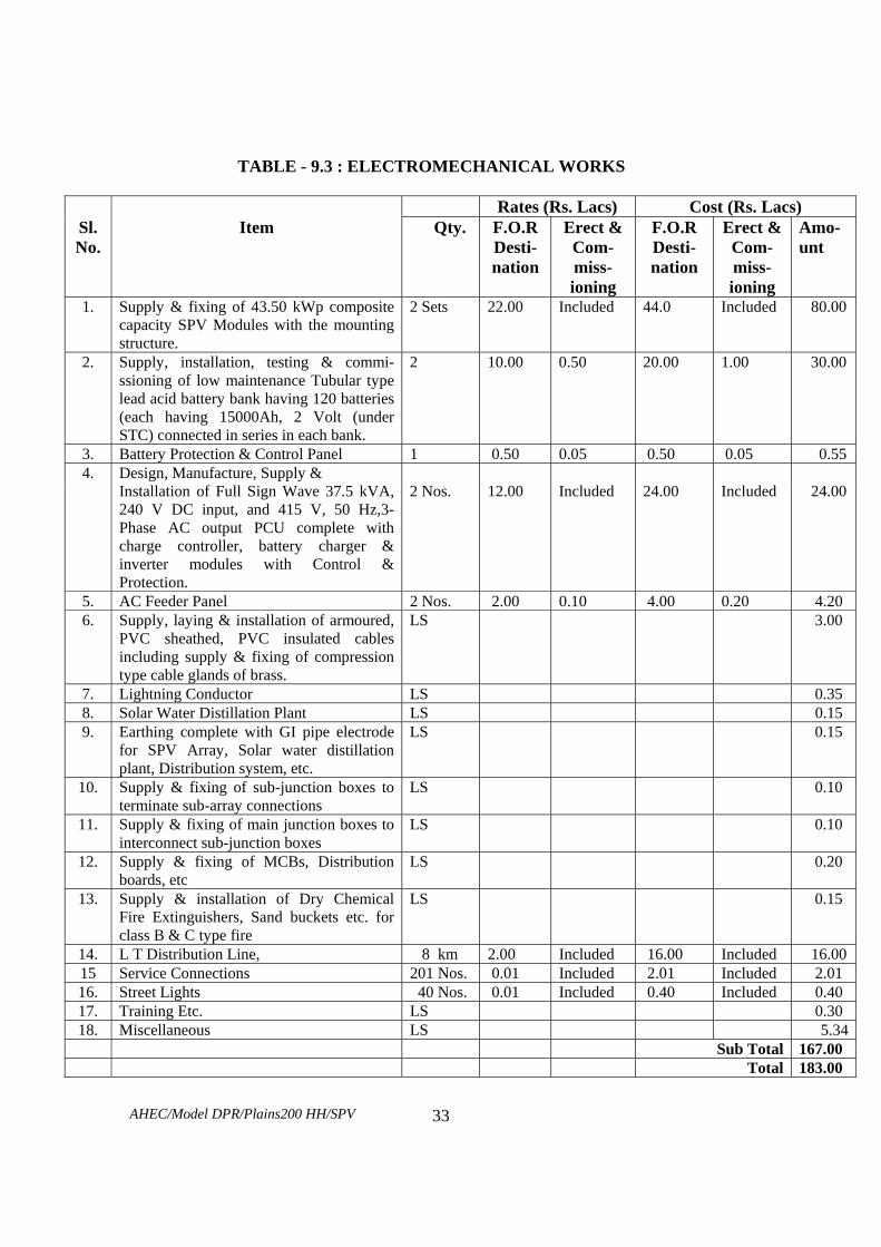
TABLE - 9.3 : ELECTROMECHANICAL WORKS
Rates (Rs. Lacs) Cost (Rs. Lacs) Sl. No.
Item Qty. F.O.R Desti- nation
Erect & Com- miss-ioning
F.O.R Desti- nation
Erect & Com- miss-ioning
Amo-unt
1. Supply & fixing of 43.50 kWp composite capacity SPV Modules with the mounting structure.
2 Sets 22.00 Included 44.0 Included 80.00
2. Supply, installation, testing & commi-ssioning of low maintenance Tubular type lead acid battery bank having 120 batteries (each having 15000Ah, 2 Volt (under STC) connected in series in each bank.
2 10.00 0.50 20.00 1.00 30.00
3. Battery Protection & Control Panel 1 0.50 0.05 0.50 0.05 0.55 4. Design, Manufacture, Supply & Installation of Full Sign Wave 37.5 kVA,
240 V DC input, and 415 V, 50 Hz,3-Phase AC output PCU complete with charge controller, battery charger & inverter modules with Control & Protection.
2 Nos. 12.00 Included 24.00 Included 24.00
5. AC Feeder Panel 2 Nos. 2.00 0.10 4.00 0.20 4.20 6. Supply, laying & installation of armoured,
PVC sheathed, PVC insulated cables including supply & fixing of compression type cable glands of brass.
LS 3.00
7. Lightning Conductor LS 0.35 8. Solar Water Distillation Plant LS 0.15 9. Earthing complete with GI pipe electrode
for SPV Array, Solar water distillation plant, Distribution system, etc.
LS 0.15
10. Supply & fixing of sub-junction boxes to terminate sub-array connections
LS 0.10
11. Supply & fixing of main junction boxes to interconnect sub-junction boxes
LS 0.10
12. Supply & fixing of MCBs, Distribution boards, etc
LS 0.20
13. Supply & installation of Dry Chemical Fire Extinguishers, Sand buckets etc. for class B & C type fire
LS 0.15
14. L T Distribution Line, 8 km 2.00 Included 16.00 Included 16.00 15 Service Connections 201 Nos. 0.01 Included 2.01 Included 2.01 16. Street Lights 40 Nos. 0.01 Included 0.40 Included 0.40 17. Training Etc. LS 0.30 18. Miscellaneous LS 5.34
Sub Total 167.00 Total 183.00

AHEC/Model DPR/Plains200 HH/SPV
34
9.2 FUNDING Rs. Lacs i. By Grant From MNES : 152.310 ii. Contribution by Villagers @ Rs. 1000/per HH : 2.01 iii. Contribution by Nodal Agency : 34.582
Total 188.902
TABLE 9.4 : COST OF GENERATION WITHOUT SUBSIDY
Sl. No. Items Rs. In Lacs
1 2 3 1 Project Cost 188.902 2 Annual Interest during Construction 6.234
3 Total Project Cost 195.136
4 Annual working expenses (as per table 9.5) 12.321 5 Interest @ 12 % on total project cost 23.416 6 Total annual expenses 35.738 7 Annual generation at power house (Million Units)
i. At 80% of Load Factor ii. At 60% of Load Factor
0.1022 0.0767
8 Cost of generation per kWh (in Rs.) i. At 80% of Load Factor ii. At 60% of Load Factor
Rs.34.968 Rs.46.625
TABLE 9.5 : STATEMENT OF YEARLY WORKING EXPENSES Sl. No.
Items Cost (Rs. In Lacs)
1 2 3 1 Operation cost @ 1% of works cost 1.889 2 Maintenance cost of C-works @ 1% 0.160 3 Maintenance of E&M works @ 2% 3.340 4 Annual depreciation charges (as per Table – 9.7) 6.932
Total 12.321

AHEC/Model DPR/Plains200 HH/SPV
35
TABLE 9.6 : COST OF GENERATION WITH SUBSIDY
Sl. No. Items Rs. in Lacs 1 2 3 1 Project Cost 188.902 2 Capital Subsidy As per MNES 152.310 3 Balance Project Cost 36.592 4 Annual Interest during Construction 1.208
5 Total Project Cost 37.800
6 Interest @ 12 % on total project cost 4.536 7 Annual working expenses ( as per table 9.6) 12.321 8 Total annual expenses 16.857
9
Annual generation at power house (Million Units) i. At 80% of Load Factor ii. At 60% of Load Factor
0.1022 0.0767
10
Cost of generation per kWh (in Rs.) i. At 80% of Load Factor ii. At 60% of Load Factor
Rs.16.494 Rs.21.993
TABLE 9.7: ANNUAL DEPRECIATION OF ASSETS
Sl. No.
Items Life in years
Cost (Rs.
Lacs)
Rate of Depreciation in %
Depreciation Rs. Lacs
1 2 3 4 5 6 1 Land Infinity 0.00 NIL NIL 2 Civil Works 35 16.00 3.40 0.544 3 Plant & System 35 151.00 3.40 5.134 4 LT Distribution 25 16.00 7.84 1.254 Total 6.932
9.3 FINANCIAL ANALYSIS
The financial analysis has been carried out as per Tables – 9.4 & 9.6. The cost of generation and the results are given below:
9.3.1 Cost Of Generation
i. Without Subsidy : Rs. 34.960/ kWh ii. With Subsidy : Rs. 16.494 / kWh

AHEC/Model DPR/Plain200 HH/SPV
36
CHAPTER -10 OPERATION AND MAINTENANCE OF PLANT & SYSTEM
10.1 GENERAL
After the plant and system is tested commissioned and the trial period is over, the operation and maintenance for 5 years period will be the responsibility of the contractor who has supplied, erected tested and commissioned the plant and the system. The contractor may net use 100% of his own staff and may require certain number of additional persons for managing O&M under the guidance of his limited staff. The Nodal Agency (CREDA) is proposed to form a Village Energy Committee (VEC) from amongst the village people to take care of the plant and the system during the initial 5 years O&M period and there-after. The VEC may arrange for the said additional staff from amongst the people of the village, depending on the age, physical so mental health, willingness and the educational qualifications.
10.2 O&M FOR INITIAL 5 YEARS
i. Regular O&M of the SPV Power Plant for a period of 5 (Five) years after commissioning along with supply of consumable items as necessary.
ii. Breakdown maintenance of the entire system including supply of necessary spare parts, if any.
iii. The O&M shall begin at the end of successful completion of the trial run of the power plant.
iv. The deputed personnel shall be qualified and well trained so that they can handle any type of operation hazard quickly and timely. These personnel shall be on round the clock duty .
v. The power plant shall be run for designated hours, therefore, the deputed personnel should attend the plant as per schedule.
vi. The security of the power plant will rest with the suppliers till such time operation and maintenance of the power plant is not handed over to the purchaser.
vii. Daily log sheet for the power plant as per format to be supplied by purchaser after commissioning of the power plant shall be maintained by the deputed personnel.
viii. The deputed personnel shall check and test all the equipment regularly, so that preventive actions, if any, could be taken well in advance to save any equipment from damage. Any abnormal behavior of any equipment shall be brought to the notice of purchaser immediately for appropriate action.
ix. Normal and preventive maintenance of the power plant such as cleaning of module surface, topping up of batteries, tightening of all electrical connections, changing of tilt angle of module mounting structure, cleaning & greasing of battery terminals, etc. are also the duties of the deputed personnel.
x. Deputed personnel will operate the plant in accordance with the availability of solar energy stored in the battery bank. Under no circumstances the operator shall take such actions those are damaging to the Power Plant and the battery bank. In case of non-availability of solar power suitable notice board may be displayed in front of the control room to avoid local problems.
AHEC/Model DPR/Plain200 HH/SPV
37
xi. During the above O&M period, if there is any loss or damage of any component of the power plant due to miss- management / mis- handling or any other reasons pertaining to the deputed personnel, what-so-ever, the contractor shall be responsible for immediate replacement / rectification at his own cost. The damaged component may be repaired or replaced by new component. It shall be ensured by the contractor that the performance of the components or the system so repaired or replaced shall not degrade.
xii. Plant operator shall be available in the Power Plant during operation period of the Power Plant.
xiii. Operating staff and personnel to be provided by the Nodel Agency / Village Energy Committee shall be guided & trained in a manner that they shall become capable of O & M of the SPV plant and system after the O & M period of 5 years is over. They will be allowed to operate the plant under the guidance of the deputed personnel for not less than 1 year before the expiry of the O & M period of 5 years.
10.3 FORMATION OF COMMITTEE FOR SUPERVISION OF O & M
i. Executive Committee
The VEC will make an Executive Committee of 5 persons which will supervise and monitor: a. Day to day functioning of the plant & system b. Monitor day to collection of revenue & Expenditure
ii. Staff
Following Staff is proposed to be appointed by VEC from amongst the villagers:
a. Manager : 1 No. b. Operational Staff : 6 Nos.
iii. Record Keeping Following record is suggested to be kept and maintained by the VEC.
a. Cash receipt register b. Cash book c. Ledger d. Bank Pass Book & Cheque Book e. General Stock & Issue Register f. Register for Consumables
iv. Supervision & Maintenance of Record a. The manager will keep maintain the record, write cash book &
maintain the account b. VEC executive will check the accounts monthly c. General Meeting of VEC will be held every quarter in which manager
will place before it the records, accounts and status of the plant. d. An annual audit of accounts assets and liabilities will be got carried out
by a competent chartered Account appointed for the purpose by the Nodal Agency. Appropriate action will be taken by the Nodal Agency after careful examination.

AHEC/ Model DPR/Plains200 HH/SPV 38
CHAPTER – 11
ENVIRONMENTAL IMPACT AND BENEFITS
11.1 ENVIRONMENTAL IMPACTS
i. The land required for the plant machinery is low and there will hardly be any adverse impact.
ii. The civil construction being of low order, thus causing almost no adverse impact.
iii. The plant being based on solar energy, it will be eco-friendly. 11.2 BENEFITS
i. There will be saving of 2 to 3 litres of Kerosene per HH per month i.e. of 5 kilolitre of Kerosine per annum.
ii. The villager use wood also for lighting as the quantity of kerosene received by
them is not enough for lighting of about half an hour one an hour or so per day. There will be saving of this wood also.
iii. There will be awareness amongst the villagers about use and misuse of forest
which will ultimately result in saving of forest from unintentional destruction (at present the village cause fire to clear the way in the forest for getting wood and do no care to ensure that the fire is not left as such to cause unintentional damage of forest.
iv. The living conditions of the villagers will improve.
v. The plant will help increase employment generation directly and indirectly.
vi. The children will be able to study better due to availability of light for good
number of hours in the late evenings.

AHEC/Model DPR/Hilly 200 HH/SPV
LIST OF PERSONNEL INVOLVEMENT
I. AHEC, IIT, ROORKEE
1. Sri Arun Kumar, Head, AHEC
2. Sri M. K. Singhal, SSO, AHEC
3. Sri Vijay Saini, SRF, AHEC
II. CONSULTANTS
1. Sri Y. S. Jadaun, Former Chief Engineer (UPSEB)
III. ASSISTANTS
1. Sri R. K. Singhal, Technical Assistant
2. Sri Chandarpal Singh, Senior Attendant
IV. CHHATTIGARH RENEWABLE ENERGY DEVELOPMENT AUTHORITY
1. Sri Rajesh Trivedi, EE
2. Sri Rajiv Gyani, SDO