soil mechanics of lunar regolith simulants for …yoshida/paperlist/spaceresource... · soil...
TRANSCRIPT

SOIL MECHANICS OF LUNAR REGOLITH SIMULANTS FOR PROBE LANDING AND
ROVER LOCOMOTION
Kazuya Yoshida*1, Keiji Nagatani*1,Genya Ishigami*1, Shigehito Shimizu*1
Kozo Sekimoto*2, Akira Miyahara*3, Takaaki Yokoyama*4
*1 Tohoku University*2 Sekimoto SE Engineering
*3 JAXA*4 Graduate University for Advanced Studies
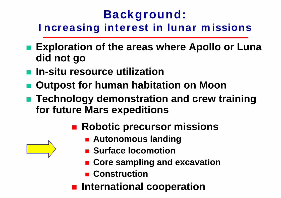
Background:Increasing interest in lunar missions
Robotic precursor missions Autonomous landingSurface locomotionCore sampling and excavationConstruction
International cooperation
Exploration of the areas where Apollo or Luna did not goIn-situ resource utilizationOutpost for human habitation on MoonTechnology demonstration and crew training for future Mars expeditions

Agenda
Autonomous precision landingImpact dynamics on regolith surfaceScaling law to infer the real motion from lab experiments
Surface locomotionWheel traction model on loose soilSoil and wheel parameters
Drilling and samplingDesign challenge for a mole-like robot

Probe LandingTo evaluate the mechanical design, control performance and landing safety of the probe,we need a simulation model that describes proper dynamics of the landing behavior.
(Movie)http://www.astro.mech.tohoku.ac.jp/
~yoshida/VideoLibrary/KD_flat_vx.mpeg

Drop Impact TestDrop and impact tests are carried out in a vacuum chamber with Lunar Regolith Simulant.
(Movie)http://www.astro.mech.tohoku.ac.jp/~yoshida/
VideoLibrary/soil_impact_landing_vacuum.mpg

Test with Scale Models
The Scaling Law is used to infer the real motion on Moon from the lab experiments with scale models.
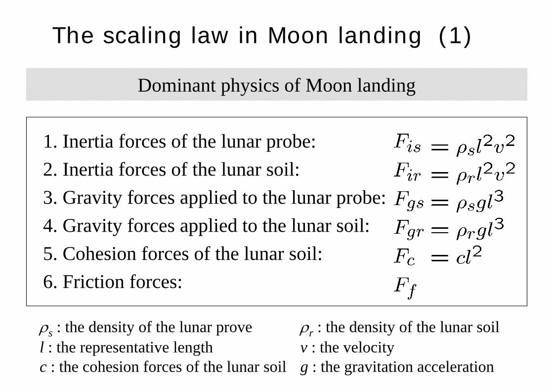
The scaling law in Moon landing (1)
Dominant physics of Moon landing
1. Inertia forces of the lunar probe:2. Inertia forces of the lunar soil:3. Gravity forces applied to the lunar probe:4. Gravity forces applied to the lunar soil:5. Cohesion forces of the lunar soil:6. Friction forces:
ρs : the density of the lunar prove ρr : the density of the lunar soill : the representative length v : the velocityc : the cohesion forces of the lunar soil g : the gravitation acceleration

Derivation of the π-numbers from the basic equations
If the scale model is 1/6 in size, the Earth-based experiments will properly simulate the motion of landing behavior on Moon.
The scaling law in Moon landing
Question:
Do we need to do our experimentsalways with a 1/6 scale model?
The answer may be NOTRelaxation of the constraints

Inertia forces
Friction forces
Gravity forces
Cohesion forces
Case A : Elimination of the cohesion forces from the law
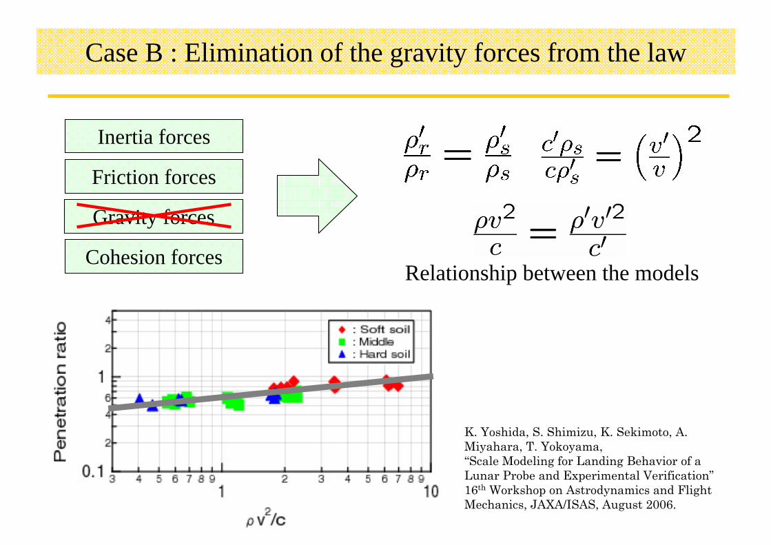
Case B : Elimination of the gravity forces from the law
Relationship between the models
Inertia forces
Friction forces
Gravity forces
Cohesion forces
K. Yoshida, S. Shimizu, K. Sekimoto, A. Miyahara, T. Yokoyama, “Scale Modeling for Landing Behavior of a Lunar Probe and Experimental Verification”16th Workshop on Astrodynamics and Flight Mechanics, JAXA/ISAS, August 2006.
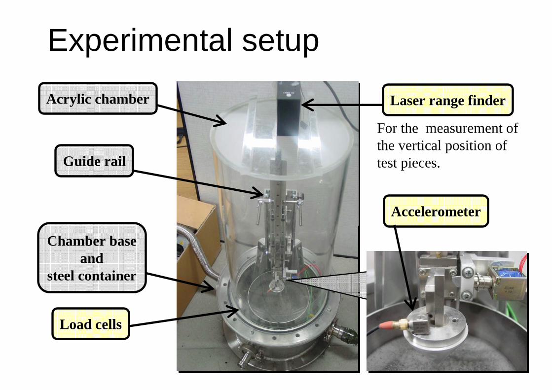
Experimental setupAcrylic chamber
Guide rail
Chamber baseand
steel container
Laser range finder
Accelerometer
Load cells
For the measurement ofthe vertical position of test pieces.

Conditions of drop tests
Specifications of test piecesShape: Circular coneTip angle: 60, 90, 120 [deg]Mass: 991, 482, 367 [g]Landing velocity: 1.4 - 2.7 [m/s]
Atmosphere: 100 [ Pa ] (1/100 atm)Soil density: 1,900-2,300 [ kg/m3 ]

Remarks 1 (Impact Landing on Regolith)
Impact dynamics for the landing on lunar regolith was studied theoretically and experimentally.
Both the theory and experiments suggest that the gravity forces have less effects than other forces to soil impact dynamics.
Even if we eliminate the gravity from our consideration, the results hold a proper approximation.
With such approximation (relaxation), we can choose any scaling ratios and use the following formula to infer the real motion dynamics from experiments:
Symbols with a prime are the values obtained ground-based experiments.Symbols without a prime are the inferred real value on the Moon.

Agenda
Autonomous precision landingImpact dynamics on regolith surfaceScaling law to infer the real motion from lab experiments
Surface locomotionWheel traction model on loose soilSoil and wheel parameters
Drilling and samplingDesign challenge for a mole-like robot

Rover Test Beds developed at Tohoku University

Research Focus on Lunar Rovers
Mechanical DesignChoice of locomotion mode: wheels, tracks, or legsChassis design
Traction ControlMakes difference in performanceSlip on loose soil
NavigationPath planning with tip-over & slip criteriaPath following with slip compensation

Experiment of Slip-Based Traction Control
• Without Slip control With Slip control(Movie)http://www.astro.mech.tohoku.ac.jp/
~yoshida/VideoLibrary/slope2.mpg
(Movie)http://www.astro.mech.tohoku.ac.jp/
~yoshida/VideoLibrary/slope1.mpg

Slip is a key state variable
Slip Ratio
( )
( )⎪⎪
⎩
⎪⎪
⎨
⎧
<−
>−
=
xx
x
xx
vrv
vr
vrr
vr
s
ωω
ωω
ω S > 0 while accelerating
S < 0 while braking

Even though the rover travels slowly, the phenomena around the wheels are dynamic.
Side slips and side forces should be also studied.
(Movie)http://www.astro.mech.tohoku.ac.jp/
~yoshida/VideoLibrary/slope_traverse02.mpg
(Movie)http://www.astro.mech.tohoku.ac.jp/
~yoshida/VideoLibrary/slope_traverse03.mpg

Traction Model for a Rigid Tire on Soft Soil
( ) ( ){ }
( ) ( ){ } θθθσθθτ
θθθτθθσ
θ
θ
θ
θ
drbDP
drbW
f
r
f
r
∫
∫−=
+=
sincos
sincos
( ) ( )( )( ) ( )( )[ ]θθθθ
ϕσθτ
sinsin1
1tan)(
−−−−−=
−+=
ff
sa
skrsa
ec
(Bekker 1956, Wong 1978)
∫= f
r
dbrTθ
θθθτ )(2
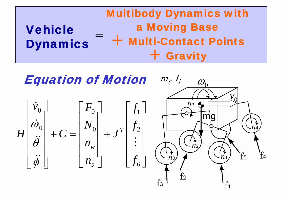
Multibody Dynamics with a Moving Base
+ Multi-Contact Points+ Gravity
Equation of Motion
⎥⎥⎥⎥
⎦
⎤
⎢⎢⎢⎢
⎣
⎡
+
⎥⎥⎥⎥
⎦
⎤
⎢⎢⎢⎢
⎣
⎡
=+
⎥⎥⎥⎥⎥
⎦
⎤
⎢⎢⎢⎢⎢
⎣
⎡
6
2
1
0
0
0
0
f
ff
J
nnNF
C
v
H T
s
w M
&&
&&
&
&
φ
θ
ω
0ω0v
mi, Ii
VehicleDynamics
=
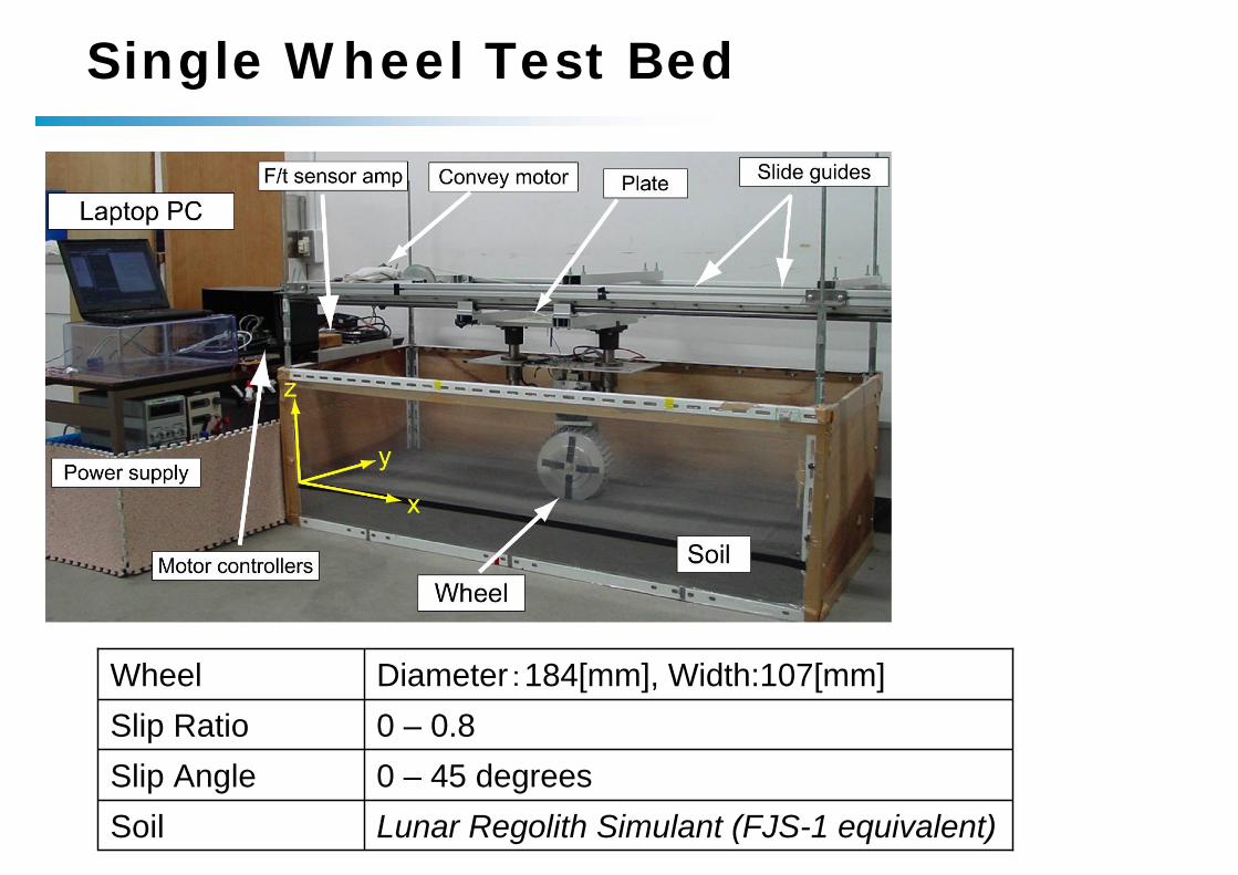
Single Wheel Test Bed
0 – 0.8Slip RatioDiameter:184[mm], Width:107[mm]Wheel
Lunar Regolith Simulant (FJS-1 equivalent)Soil0 – 45 degreesSlip Angle

Experimental Results (longitudinal force)
Slip angle : Small
Slip angle : Large
G. Ishigami, A. Miwa, K. Ngatani, K. Yoshida“Terramechanics-based Model for Steering Maneuver of Planetary Exploration Rovers on Loose Soil”Journal of Field Robotics vol.24, 2007 (to appear)

Experimental Results (side force)
Slip angle : Small
Slip angle : Large
G. Ishigami, A. Miwa, K. Ngatani, K. Yoshida“Terramechanics-based Model for Steering Maneuver of Planetary Exploration Rovers on Loose Soil”Journal of Field Robotics vol.24, 2007 (to appear)

Traction Model for a Rigid Tire on Soft Soil
( ) ( ){ }
( ) ( ){ } θθθσθθτ
θθθτθθσ
θ
θ
θ
θ
drbDP
drbW
f
r
f
r
∫
∫−=
+=
sincos
sincos
( ) ( )( )( ) ( )( )[ ]θθθθ
ϕσθτ
sinsin1
1tan)(
−−−−−=
−+=
ff
sa
skrsa
ec
(Bekker 1956, Wong 1978)
∫= f
r
dbrTθ
θθθτ )(2 Key parameters:
c : soil cohesionϕ : friction anglek : shear deformation
modulus

Slope Climbing Experiment Slope Climbing Experiment at JAXA Aerospace Research Centerat JAXA Aerospace Research Center
Lunar Regolith Simulantarbitrary inclination 0-30 deg or over

Slope Traversing Experiment Slope Traversing Experiment at JAXA Aerospace Research Centerat JAXA Aerospace Research Center
Lunar Regolith Simulantarbitrary inclination 0-30 deg or over
Red is simulation, blue is experimentExperimental trace

Path Planning and Control Path Planning and Control Execute pathExecute path--tracking navigation with taking the tracking navigation with taking the longitudinal and lateral slip effects into account.longitudinal and lateral slip effects into account.
Kinematics-based control Dynamics-based control
Genya Ishigami, Keiji Nagatani, and Kazuya Yoshida, "Path Following Control with Slip Compensation on Loose Soil for Exploration Rover",Proceedings of the 2006 IEEE/RSJ International Conference on Intelligent Robots and Systems, pp. 5552-5557, 2006

Remarks 2 (Locomotion on Loose Soil)
Traction mechanics of a rigid wheel on loose soil has been clarified using an analytical model and validated by laboratory experiments.Key parameters of the traction mechanics are soil cohesion, friction angle and shear deformation modulus.But the shear deformation modulus is a magic number, which represents the wheel-soil interaction for each wheel-soil combination.If we can measure the slippage (both in longitudinal and lateral directions) on board, smart path following control of a rover with slippage compensation will be achieved.
Open question: how to measure the slippage by only onboard sensors?

Agenda
Autonomous precision landingImpact dynamics on regolith surfaceScaling law to infer the real motion from lab experiments
Surface locomotionWheel traction model on loose soilSoil and wheel parameters
Drilling and samplingDesign challenge for a mole-like robot

Design Challenge for Excavation and Transportation
These simulation movies werecreated in 1999
(Movie)http://www.astro.mech.tohoku.ac.jp/lunar-mission/mog-rov1.mpg
(Movie)http://www.astro.mech.tohoku.ac.jp/lunar-mission/mog-rov4.mpg

Design Challenge for Excavation and Transportation
MOGURA2001
(Movie)http://www.astro.mech.tohoku.ac.jp/~yoshida/VideoLibrary/mog-rov1.mpg

Design Challenge for Excavation and Transportation
MOGURA2001
(Movie)http://www.astro.mech.tohoku.ac.jp/~yoshida/VideoLibrary/mog-rov2.mpg
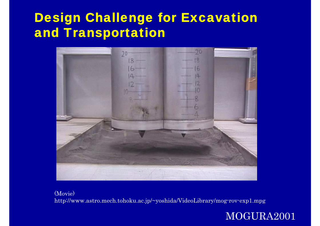
Design Challenge for Excavation and Transportation
MOGURA2001
(Movie)http://www.astro.mech.tohoku.ac.jp/~yoshida/VideoLibrary/mog-rov-exp1.mpg

Design Challenge for Excavation and Transportation
MOGURA2001
(Movie)http://www.astro.mech.tohoku.ac.jp/~yoshida/VideoLibrary/mog-rov-exp2.mpg

Remarks 3 (Robotic Excavator)A test bed for a mole-like self-excavation (tunnel builder) robot was developed and tested using Lunar RegolithSimulant.
Double-roter system was introduced to cancel the reaction each other. This idea was successful.
A conveyer mechanism to transport the soil ejecta from the cutting front (bottom) to above the surface was necessary to make the robot move forward.
By virtue of the double-roter system and the soil conveyer mechanism, the robot successfully sank into the soil by its own weight, without any rig to support or push the robot.
The excavation was successful as deep as the length of the robot body, but difficult to dig more than that, due to the increased soil resistance. More study is necessary to analyze the mechanics to limit the excavation depth.
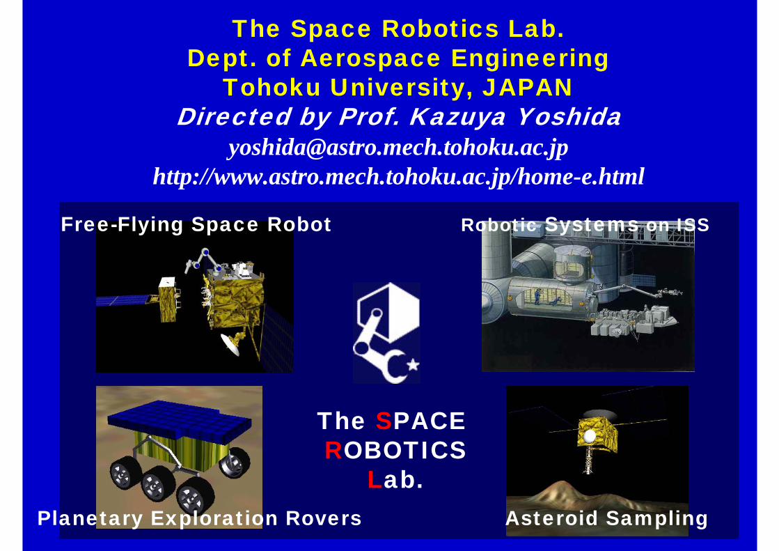
The Space Robotics Lab.Dept. of Aerospace Engineering
Tohoku University, JAPANDirected by Prof. Kazuya Yoshida
[email protected]://www.astro.mech.tohoku.ac.jp/home-e.html
Free-Flying Space Robot
Planetary Exploration Rovers Asteroid Sampling
Robotic Systems on ISS
The SPACE ROBOTICS
Lab.