soil mechanics - uomisan.edu.iq · aassssiisstt..lleecctt..oommaarrttaahhaa 2 faculty of...
TRANSCRIPT

2012-2013
PREPARED BYASSIST. LECTURER OMAR TAHA
COURSE BOOK FOR 4th STAGE CIVIL ENGINEERING STUDENTS
2012-2013
PREPARED BYASSIST. LECTURER OMAR TAHA
COURSE BOOK FOR 4th STAGE CIVIL ENGINEERING STUDENTS
2012-2013
PREPARED BYASSIST. LECTURER OMAR TAHA
COURSE BOOK FOR 4th STAGE CIVIL ENGINEERING STUDENTS

2AAAssssssiiisssttt ... LLLeeecccttt ... OOOmmmaaarrr TTTaaahhhaaa
Faculty of EngineeringSchool of Architecture and ConstructionCivil Engineering Department
Course InformationAcademic Year 2012-2013Stage 4th StageCourse Title Foundation EngineeringCourse Code CE 402Weekly Load 4 hrs. (2 hr Theoretical + 2 hr tutorial)Instructor Assist. Lecturer : Omar TahaSchool /Department School of Engineering Civil Engineering DepartmentInstructor Contact Email: [email protected] Name Dr. Faris RashiedCoordinator Contact Email: faris.rashied@ koyauniversity.orgText Book Joseph E. Bowles, RE.,bS.E " Foundation Analysis and Design"5Th Edition (1997)
Course Overview
This course is a prerequisite for the CE 303 soil mechanics course. This is a fundamental course in theCivil and Geotechnical Engineering Programs. The course on "Foundation" presents guidance forselecting and designing foundations for buildings and facilities of all types and associated features forbuildings such as earth embankments and slopes, retaining structures. Foundation design differsconsiderably from design of other elements of a structure because of the interaction between the structureand the supporting medium (soil and rock). The soil and rock medium are highly variable as compared tosteel and concrete products above the soil; therefore, much attention is given to presenting subsurfaceinvestigation methods to better determine the properties of the soil and rock.
Course Objectives
The objective of this course is to introduce students that they will be able to: Select boring location, depth, and associated laboratory tests for the project. Select and design the appropriate shallow foundation system and deep foundation system utilizing
boring log data and associated laboratory testing and incorporating the following considerations;(a. Soil type, b. Settlement, c. Loads, d. Alternatives: mat, spread footing, combined footing, e. Cost.)
Prepare a geotechnical engineering design report for a shallow and/or deep foundation systemincluding, but not limited to, appropriate engineering analysis, discussion of alternatives, presentationof field and laboratory data, and final foundation design recommendations.
Perform a time rate of consolidation analysis. Perform a retaining wall analysis including sliding and overturning considerations.
References1. Braja M. Das "Principles of Foundation Engineering" 7th Edition (2011).2. V.N.S. Murthy, "Geotechnical Engineering: Principles and Practices of Soil Mechanics and Foundation
Engineering"(2002)3. Braja M. Das "Theoretical Foundation Engineering" (2007).4. Dr. Fu Hua Chen, P.E." Soil Engineering: Testing, Design, and Remediation" (1999).5. T. William Lambe & Robert V. Whitman "Soil Mechanics" 3rd edition (1979).

3AAAssssssiiisssttt ... LLLeeecccttt ... OOOmmmaaarrr TTTaaahhhaaa
Grading Scheme:
Exams & Quizzes MarksExam Quizzes
First Semester 15% 5%Second Semester 15% 5%Final Exam 60% -
Course Policies:
1. No Cell Phone is allowed during lecture and exam. Must be OFF (not silence orvibrating mode).
2. Be on time to class. Tardy is strongly discouraged.3. Exams and Quizzes are closed book and closed notes.4. You should bring calculator to every lecture.5. Ten-minutes break per each hour; it will be given at the end of the lecture.
Syllabus of Foundation Course & Schedule
No. of Weeks TopicFour Weeks Site InvestigationFive Weeks Bearing Capacity of Foundation
Three Weeks Shallow FoundationThree Weeks Foundation SettlementsFour Weeks Deep Foundation (Single Piles)Three Weeks Deep Foundation (Group piles)Two Weeks Lateral Earth PressureTwo Weeks Retaining WallsTwo Weeks Sheet pile WallsTwo Weeks Slope Stability Analysis

4AAAssssssiiisssttt ... LLLeeecccttt ... OOOmmmaaarrr TTTaaahhhaaa
Chapter OneSite Investigation
1-1IntroductionInvestigation of the underground conditions at a site is prerequisite to the economicaldesign of the substructure elements. The field and laboratory investigations requiredto obtain the essential information on the subsoil is called Soil Exploration or SoilInvestigation.1-2 Objectives:Generally the purpose of a soil exploration program is to provide the followings:1) Information to determine the type of foundation required (shallow or deep).2) Information to allow the geotechnical consultant to make a recommendation on
the allowable load capacity of the foundation.3) Sufficient data/laboratory tests to make settlement predictions.4) Location of the ground water table (or determination of whether it is in the
construction zone).5) Information so that the identification and solution of construction problems
(sheeting and dewatering or rock excavation) can be made.6) Identification of potential foundation problems (expansive soil, collapsible soil,
etc.) concerning adjacent property.7) Identification of construction methods for changing subsoil conditions.1-3 Execution of Soil Exploration ProgramThe three limbs of a soil exploration are:-1) Planning.2) Execution.3) Report writing.1-4 Methods of InvestigationsA- Direct methods.B- Indirect Methods.1-5 Factors Affecting the Choice of the Exploratory Borings Methods:The most suitable method to perform subsoil exploration depends on the following factors:1) Purpose and information required.2) Equipment availability.3) Experience and training of available personal.4) Depth of hole.5) Type of soil in the general area.6) Terrain and accessibility.7) The amount of money allocated for the exploration.8) Environmental Impacts.9) Disruption of existing structure.

5AAAssssssiiisssttt ... LLLeeecccttt ... OOOmmmaaarrr TTTaaahhhaaa
1-6 Sampling and Samples:-1) Disturbed Samples.2) Undisturbed Samples.3) Remolded Samples.
1-7 Number, Spacing and Depth of BoringThe spacing of borings can not be determined with absolute exactness. They depend upon:1) Nature and condition of soil.1) The shape and extent of building.2) Importance of the project (cost of boring).
1-8 Soil Testing1) Laboratory Tests.2) In-situ Test (Field Tests):A- Standard Penetration TestB- Cone Penetration Test (CPT):1) Dynamic Cone Penetration Test.2) Static (Dutch) Cone Penetration Test.C) Field Vane Shear Testing (FVST).D) Field Plate Load Test.
1-9 Housel's (1929) Method of Determining Safe Bearing Pressure fromSettlement Consideration:
The method suggested by Housel for determining the safe bearing pressure onsettlement consideration is based on the following formula:
Q = A m + P n
6AAAssssssiiisssttt ... LLLeeecccttt ... OOOmmmaaarrr TTTaaahhhaaa
Chapter TwoBearing Capacity of Foundation
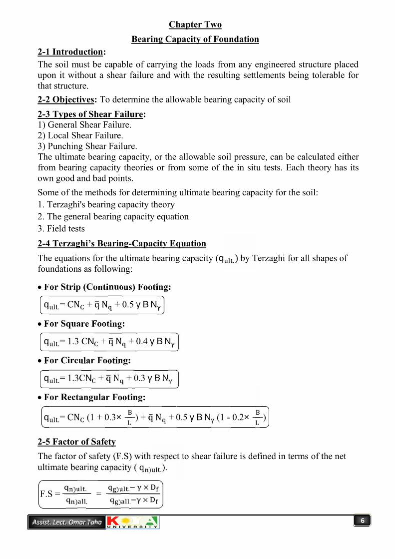
2-1 Introduction:The soil must be capable of carrying the loads from any engineered structure placedupon it without a shear failure and with the resulting settlements being tolerable forthat structure.2-2 Objectives: To determine the allowable bearing capacity of soil2-3 Types of Shear Failure:1) General Shear Failure.2) Local Shear Failure.3) Punching Shear Failure.The ultimate bearing capacity, or the allowable soil pressure, can be calculated eitherfrom bearing capacity theories or from some of the in situ tests. Each theory has itsown good and bad points.Some of the methods for determining ultimate bearing capacity for the soil:1. Terzaghi's bearing capacity theory2. The general bearing capacity equation3. Field tests2-4 Terzaghi’s Bearing-Capacity EquationThe equations for the ultimate bearing capacity (q .) by Terzaghi for all shapes offoundations as following:
For Strip (Continuous) Footing:q .= CN + q N + 0.5 γ B NFor Square Footing:q .= 1.3 CN + q N + 0.4 γ B NFor Circular Footing:q .= 1.3CN + q N + 0.3 γ B NFor Rectangular Footing:q .= CN (1 + 0.3× ) + q N + 0.5 γ B N (1 - 0.2× )
2-5 Factor of SafetyThe factor of safety (F.S) with respect to shear failure is defined in terms of the netultimate bearing capacity ( q ) .).F.S = ) .) . = ) . ×) . ×

7AAAssssssiiisssttt ... LLLeeecccttt ... OOOmmmaaarrr TTTaaahhhaaa
2-6 Effect of Water Table on Bearing Capacity:The bearing capacity equations are affected due to the presence of the water table.The following cases may be considered here:Case I: When the water table lies above or at the base of the foundation, then the overburdenpressure (q) in the second term of the bearing capacity equations takes the form:
(Overburden pressure) q = D × γ + D (γ .- γ )
Also the value of (γ) in the third term has tobe replaced by (γ .): γ . = (γ .- γ )
Case II: When the water table lies within depth < B below the base of thefoundation, whereas (o < d < B), then the overburden pressure (q) in the secondterm of the bearing capacity equations takes the form:q = γ × DThe value of (γ) in the third term of the bearing capacity equations must be replacedby the value of (γ*) which can be calculated as:ω = 0.5 + 0.5 γ* = ω × γCase III: When the water table is located at depth ≥ B, the water will have no effecton the ultimate bearing capacity.
2-7 Meyerhof’s Bearing-Capacity Equation:Meyerhof (1951, 1963) proposed a bearing capacity equation similarto that of Terzaghi but included the shape factors, depth factors andinclination factors for cases where the footing load is inclined fromthe vertical.
Equations:1) For vertical load:q .= C N S d + q N S d + 0.5 γ B N S d2) For Inclined load:q .= C N i d + q N i d + 0.5 γ B N i d
B
DP
°
B
DP
∇dG.W.T D
dD D∇ Case I
G.W.T Case II∇B
G.W.T

8AAAssssssiiisssttt ... LLLeeecccttt ... OOOmmmaaarrr TTTaaahhhaaa
2-8 Hansen's Bearing-Capacity Method:Hansen (1970) proposed the general bearing-capacity equation. This equation isreadily seen to be a further extension of the earlier Meyerhof (1951) work.Equations:
1) For (C-∅) Soil:q .= C N S d i b g + q N S d i b g + 0.5 γ B N S d i b g2) For Clay (∅ = 0):q .= 5.14 Su (1+ Sc′ + dc′- ic′ - bc′ -gc′ ) + q2-9 Bearing Capacity of Foundations Subjected to Eccentric Loads:Generally when the footing subjected to eccentric loads there are two approaches.(1) Conventional method:
Find out the maximum stress and minimum stress under the footing using:
q = (1+ × + × ) ≤ qq = (1- × - × ) ≥ Zero
(2) Meyerhof’s Approach:Research and observation [Meyerhof (1953, 1963) and Hansen (1970)] indicatethat effective footing dimensions obtained as:
B′ = B - 2e L′ = L - 2eq .= . ≥ q .= .×
2-10 Bearing Capacity of Footings on Slopes:A special problem that may be encountered occasionally is that of a footing located onor adjacent to a slope.2-11 Bearing Capacity from Field Tests1) Bearing Capacity from Standard Penetration Test (SPT)2) Bearing Capacity from Cone Penetration Test (CPT)

9AAAssssssiiisssttt ... LLLeeecccttt ... OOOmmmaaarrr TTTaaahhhaaa
Chapter ThreeShallow Foundation
3-1 Introduction:Shallow foundations are those foundations are founded near to the finished ground surface.3-2 Objectives of foundation: The objective of foundation is to transfer the loadsof superstructure to the subsoil safely:1) Without exceeding the load carrying capacity of the subsoil strata.2) Without causing settlements which exceed the permissible limit.
Foundation: is the lower part of the building or any other structure which transfersthe load and distribute it on the soil.Foundation Design: a good foundation design ensures that structural loads(including weight of foundations) are transferred to the ground safely andeconomically.Foundation can be classified according to its depth to the width into two types:1) Shallow Foundation (D ≤ B)2) Deep Foundation (D >> B).
3-3 Types of Shallow Foundation:1) Spread (Isolated or Single) Footing: A footing carrying a single column is
called a spread footing... Spread footing can be seen as:A) Column Footing.B) Stepped Footing.C) Sloped Footing.D) Wall Footing.Figure (3-1) below shows the types of the spread footing:
Figure (3-1): Typical footings, (a) Single or spread footings; (b) Stepped footing;(c) Sloped footing; (d) Wall footing; (e) Footing with pedestal.

10AAAssssssiiisssttt ... LLLeeecccttt ... OOOmmmaaarrr TTTaaahhhaaa
2) Combined Footing: When a footing supports a line of two or more columns, it iscalled a combined footing. A combined footing may have either rectangular ortrapezoidal shape. These several footing types are illustrated as shown below:A) Rectangular FootingB) Trapezoidal FootingC) Strap or Cantilever
The figure (3-2) below shows the types of the combined footing:
3) Raft (Mat) Foundation:A mat foundation is a large concrete slab used to interface one column or moreone column in several lines, with the base soil. The figure below illustratesseveral mat configurations as might be used for buildings.
Figure (3-3): Common types of mat foundations, (a) Flat plate; (b) plate thickened undercolumns; (c) waffle-slab; (d) plate with pedestals; (e) basement walls as part of mat.
Figure (3-2): (A) Rectangular Footing (B) Trapezoidal Footing (C) Strap Footing

11AAAssssssiiisssttt ... LLLeeecccttt ... OOOmmmaaarrr TTTaaahhhaaa
3-4 Design of Dimensions of Footings:Allowable Bearing Capacity ( ): The maximum pressure which the soil can carrysafely without risk of neither shear failure nor excessive settlement (units: kN/m ).VA ≤ qThe design of any foundation can be of two approaches:1) Uniform Pressure Intensity: This is done by locating thelocation of the resultant of the columns loads (R) at the samelocation of the center of gravity of the plan of footing.q = VA ≤ q2) Increasing Pressure Intensity: This is done when the location of the resultant ofthe columns loads on a footing (R) does not pass through the center of the footing,the footing is subjected to what is called eccentric loading, this will developincreasing pressure intensity as shown in figure below, and this will cause nonuniform pressure.The intensity of the pressure developed under the foundation can be expressed as:
q = (1+ × + × ) ≤ qq = (1-
×- × ) ≥ Zero
qV
A = B × L

12AAAssssssiiisssttt ... LLLeeecccttt ... OOOmmmaaarrr TTTaaahhhaaa
Chapter FourFoundation Settlements
4-1ObjectivesFoundation settlements must be estimated with great care for buildings, bridges,towers, power plants, and similar high-cost structures to avoid the damage of thestructure. The total settlement of a foundation comprises of three parts as follows:S .= S + S + S4-2 Immediate Settlement: This occurs due to elastic deformation of dry soils andof moist soils without any change in water content.
S = q . × B ( )× I4-3 Consolidation Settlement: Consolidation settlement occurs in saturated clayeysoils when they are subjected to increment load caused by foundation construction.The final consolidation settlement can be calculated by using one of the followingcorrelations:S = ( ∆ )× HS = m × ∆p × HS = × H log ∆
For Normally Consolidated Clay (N.C.C.), (O.C.R. ≤1)
For Over Consolidated Clay (O.C.C.), (O.C.R. >1)
A) If p +∆p ≤ p , then use;S = × H log ∆B) If p +∆p > p , then use;S = × H log + × H log ∆4-4 Secondary Settlement: After primary consolidation the soil structure continuesto adjust to the load for some additional time.S = C∝ × H log

13AAAssssssiiisssttt ... LLLeeecccttt ... OOOmmmaaarrr TTTaaahhhaaa
Chapter FiveDeep Foundation (Single Piles)
5-1 IntroductionPiles are structural members of timber, concrete, and/or steel that are used totransmit surface loads to lower levels in the soil mass.The major uses of piles are:1. To carry vertical compression load.2. To resist uplift load.3. To resist horizontal or inclined loads
5-2 Classification of Piles:A) According to Their Materials Timber Piles, Concrete Piles Steel Piles.
B) According to the method of construction Driven piles, Bored piles
5-3 Determination of Bearing Capacity:
The ultimate bearing capacity of pile Qult , is generally represented by theformula:
Qult = Qb + Qs
Qb: Ultimate bearing resistance available.Qs : Ultimate shaft resistance available.
A)Bearing capacity of piles in cohesive soils ( = 0)B) Bearing capacity of piles in cohesionless soils (Cu = 0)C) Pile capacity in (C - soils)
5-4 Objectives:Upon completion of this semester, students will be able to
Design and Analysis of Deep Foundations Calculate side and tip capacity of driven piles in clay Calculate side and tip capacity of driven piles in sand

14AAAssssssiiisssttt ... LLLeeecccttt ... OOOmmmaaarrr TTTaaahhhaaa
Chapter SixDeep Foundation (Group Piles)
6-1 IntroductionWhen several pile butts are attached to a common structural element termed apile cap the result is a pile group. Typical arrangements of piles are shown.
6-2 Group Action:When a pile is installed immediately adjacentto each other the respective bulbs of verticalpressure can overlap as shown in figure.
6-3 Efficiency of Pile Group (Eg):Since the pile group is not necessarily equal to the sum of the capacities of thepiles in the group. In general
Eg =( )( ) ×
The efficiency calculates for:A)Pile groups in cohesive soils ( = 0)B) Pile groups in cohesionless soils (Cu = 0)
6-4 Pile Groups Subjected to Moment:To calculate the ultimate bearing capacity for each pile in a group subjected to moment.
P = ∑ ± ×∑ ± ×∑6-5 Settlement of Pile Group
1- Consolidation settlement of pile groups2- Elastic settlement of pile groups
15AAAssssssiiisssttt ... LLLeeecccttt ... OOOmmmaaarrr TTTaaahhhaaa
Chapter SevenLateral Earth Pressure
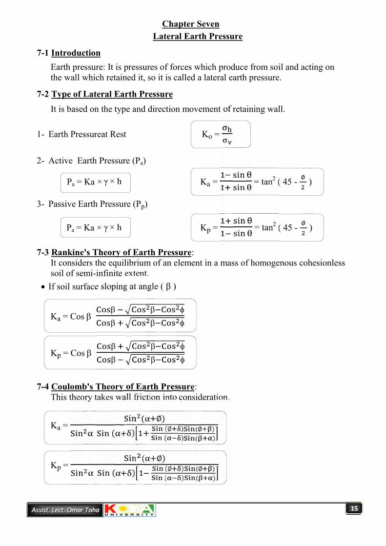
7-1 IntroductionEarth pressure: It is pressures of forces which produce from soil and acting onthe wall which retained it, so it is called a lateral earth pressure.
7-2 Type of Lateral Earth PressureIt is based on the type and direction movement of retaining wall.
1- Earth Pressureat Rest Ko =
2- Active Earth Pressure (Pa)
Pa = Ka × γ × h Ka = = tan2 ( 45 - ∅ )
3- Passive Earth Pressure (Pp)
Pa = Ka × γ × h Kp = = tan2 ( 45 - ∅ )
7-3 Rankine's Theory of Earth Pressure:It considers the equilibrium of an element in a mass of homogenous cohesionlesssoil of semi-infinite extent.
If soil surface sloping at angle ( )
Ka = Cos
Kp = Cos
7-4 Coulomb's Theory of Earth Pressure:This theory takes wall friction into consideration.
Ka =( ∅)( ) (∅ ) (∅ )( ) ( )
Kp =( ∅)( ) (∅ ) (∅ )( ) ( )

16AAAssssssiiisssttt ... LLLeeecccttt ... OOOmmmaaarrr TTTaaahhhaaa
Chapter EightRetaining Walls
8-1 IntroductionBoth the Rankine and Coulomb methods are widely used to compute the lateralearth pressure on retaining walls. To check the stability of retaining wall, thefollowing steps are used:
1- Check for overturning. F. S( ) =∑∑
2- Check for sliding along the base. F. S( ) =∑∑
3- Check the bearing capacity failure of the base. F. S( ) =
Chapter NineSheet Pile Wall
9-1 IntroductionSheet pile walls are retaining walls constructed to retain earth, water or any otherfill material. These walls are thinner in section as compared with retaining wall.Sheet pile walls are generally used for the following:
1. Water front structures, for example, in building wharfs, quays, and piers2. Building diversion dams, such as cofferdams3. River bank protection4. Retaining the sides of cuts made in earth
Sheet piles may conveniently be used in several civil engineering works:1. Cantilever sheet piles: the piles are fixed only at the bottom and are free at the top.2. Anchored bulkheads: the lower ends are driven into the earth and the upper ends are
anchored by tie or anchor rods.There are several methods of analyzing cantilever and anchored sheet-pile walls:
1. Free earth support2. Fixed earth support:

17AAAssssssiiisssttt ... LLLeeecccttt ... OOOmmmaaarrr TTTaaahhhaaa
Chapter TenSlope Stability Analysis
10-1 IntroductionThe static stability of slopes of earth and rock-fill dams, slopes of other typesof embankments, excavated slopes, and natural slopes in soil and soft rock.This course is designed to give students a thorough understanding of theanalysis of the stability of natural and engineered slopes. Emphasis will beplaced on the use of limit equilibrium methods to analyze slopes using fieldand laboratory data. Discussion on the probabilistic analysis of slopes, alongwith stabilization of failed slopes, will also be presented.
10-2 Objectives:
1. Learn the principles of slope stability; factors that affect slope stability;methods of analyzing stability of slopes and embankments.
2. Learn how to site, design and analyze earth dams; acquaint the student with thebasic principles of large earth dam engineering; learn how to evaluate damstability and seepage.
3. Learn how to continue to learn about slope stability and dams after the course.

18AAAssssssiiisssttt ... LLLeeecccttt ... OOOmmmaaarrr TTTaaahhhaaa
School of Engineering Date: -/-/-Civil Eng. Department Exam Time: 90 minutes.
Q1-A): Check the adequacy of four square spreadfooting (2×2× 0.5) m shown below for thefollowing data:
Weight of tower = 600 kN (weight of foundation not included) Moment due to wind = 2500 kN.m Minimum factor of safety is (3) concrete = 25 kN/m3 , water = 10 kN/m3
Q1-B): For the wall footing shown in figure. Findmoment (M) to give equal pressuredistribution q . = 180 kpa.
Q2-A): Check the following square footing byusing Terzaghi’s bearing capacityequation, given (FS = 2.5), P = 4000 kN.
2m
V = 500 kN/m
1m
M =?
(2×2×0.5) m
7 m
7 m
Wind
3×3m
Sand ∅ = 30°γ = 19 kN/mGs = 2.7
1 m
2 m ∇∇
W.T 1.5 m
4 m
8 m
Tower
= 26ºsat. = 17 kN/m3
dry= 11.11 kN/m3
C= 130 = 30º
sat. = 19 kN/m3

19AAAssssssiiisssttt ... LLLeeecccttt ... OOOmmmaaarrr TTTaaahhhaaa
Q2-B) Design spread footings for the three columns shown infigure and sketch the layout, q . = 150 kpa.
Column Dimension LoadA 0.3 × 0.3 500B 0.3 × 0.3 700C 0.4 × 0.4 900
Q3): What is the purpose of the site investigation?
B C
A
3 m
3 m

20AAAssssssiiisssttt ... LLLeeecccttt ... OOOmmmaaarrr TTTaaahhhaaa
Answers:Q1-A/
H = 0.5B tan (45 + ∅ )
H = 0.5×2 tan (45 + ) = 1.6 m
The effective depth shear (H) within the first layer.
Forces per leg of foundation:
According to weight of tower = = 150 kN
According to moment = = 357.14 kN ÷ 2 = 178.6 kN
Max. Force per leg = 150 + 178.6 = 328.6 kN
Min. Force per leg = 150 178.6 = 28.6 kN
Check F.S against uplift:
Total weight of footing = (2×2×0.5×25) + (2×2×1×11.11) =94.4 kN
Uplift force = 28.6 kN
F.S against uplift =.. = 3.3 > 3 o.k.
Check F.S against shear failure:
qu = C Nc Sc dc + q' Nq Sq dq + 0.5 B N S d
q' = 1.5×12 =18 kN/m2
From Table (2-3), for = 26º
Nq = 11.8, N =7.9
Sq = 1 + tan ( ) = 1 + tan 26 × ( ) = 1.4877
S = 1 0.4 ( ) = 1 0.4× ( ) = 0.6
= 1.52 = 0.75 <1
Then:
(2×2×0.5) m
7 m
7 m
Wind
W.T 1.5 m
4 m
8 m
Tower
= 26ºsat. = 17 kN/m3
dry= 12 kN/m3
C= 130 = 30º
sat. = 19 kN/m3

21AAAssssssiiisssttt ... LLLeeecccttt ... OOOmmmaaarrr TTTaaahhhaaa
dq = 1 + 2tan (1- sin)2 ( ) = 1 + 2tan (26) (1- sin 26)2 (.
) = 1.23
d =1
qult.)g = 18×11.8×1.4877×1.23 + 0.5× (1710) ×2×7.9×0.6×1= 421.844 kN/m2
qact)g = =. .× = 105.75 kN/m2 ≤ q .)g
F.S = .) ×.) × =. . = 4.6 O.k.
Q1-B)∵ Uniform soil pressure
L = (d + e) × 2
3 = (1 + e) × 2∴ e = 0.5 m
e =
0.5 =
M = 250 kN.m/m
Q2-A/γ . = (γ )19 = . (10) ∴ e = 0.88γ = (γ ) = . . (10) = 14.3 kN/mApply the ultimate B.C equation for square footing;q .=1.3 CN + q N + 0.4 γ B NFrom Table (2.1) for ∅ = 30°N = 22.5 and N = 19.7q = 14.3 × 2 + (19 – 10) × 1 = 37.6 kN/mγ . = (γ .– γ )
2m
V = 500 kN/m
1m
M =?
3×3m
Sand ∅ = 30°γ = 19 kN/mGs = 2.7
1 m
2 m ∇∇

22AAAssssssiiisssttt ... LLLeeecccttt ... OOOmmmaaarrr TTTaaahhhaaa
γ .= 19 – 10 = 9 kN/mq .=0 + 37.6 × 22.5 + 0.4 × 9 × 3 × 19.7
= 1058.76 kN/mFind ( q )q ) =
qult.)g ×. + ( γ × D )q ) =. . + (37.6) = 548.18 kN/m
Find the actual pressure on soil;q .= .P . = 4000 + 3 × 3× 1× 24 + 3 × 3× 2× 14.3 = 4473.4 kNq .= .× = 497 kN/m < q ) = 548.18 kN/m ok
Q2-B)
B (m) L (m)
Col. (A) Area = = 3.33 1.83 1.83
Col. (B) Area = = 4.66 2.2 2.2
Col. (C) Area = = 6.0 2.45 2.45
2.6 –. – .
= 0.46
2.6 –. – .
= 0.585
3 –. – .
= 0.6752.6 m 0.585 m
B C
A
0.675 m
0.46 m

23AAAssssssiiisssttt ... LLLeeecccttt ... OOOmmmaaarrr TTTaaahhhaaa
Q3 / the purpose of a soil exploration program is to provide the followings:
1) Information to determine the type of foundation required (shallow or deep).
2) Information to allow the geotechnical consultant to make a recommendation onthe allowable load capacity of the foundation.
3) Sufficient data/laboratory tests to make settlement predictions.
4) Location of the ground water table (or determination of whether it is in theconstruction zone).
5) Information so that the identification and solution of construction problems(sheeting and dewatering or rock excavation) can be made.
6) Identification of potential foundation problems (expansive soil, collapsible soil,etc.) concerning adjacent property.
7) Identification of construction methods for changing subsoil conditions.