software requirements specification (srs) …€¦ · · 2007-02-11software requirements...
TRANSCRIPT

SOFTWARE REQUIREMENTS SPECIFICATION (SRS)FOR THE DALLAS / FT. WORTH REGIONAL
CENTER-TO-CENTER COMMUNICATIONS NETWORK
Version 3.0
December 5, 2001
Prepared for:
Software Task Force
NORTH CENTRAL TEXAS COUNCIL OF GOVERNMENTS616 Six Flags Drive
P.O. Box 5888Arlington, TX 76005-5888
Prepared by:
SOUTHWEST RESEARCH INSTITUTEPost Office Drawer 28510, 6220 Culebra Road
San Antonio, Texas 78228-0510
SOFTWARE REQUIREMENTS SPECIFICATION ii
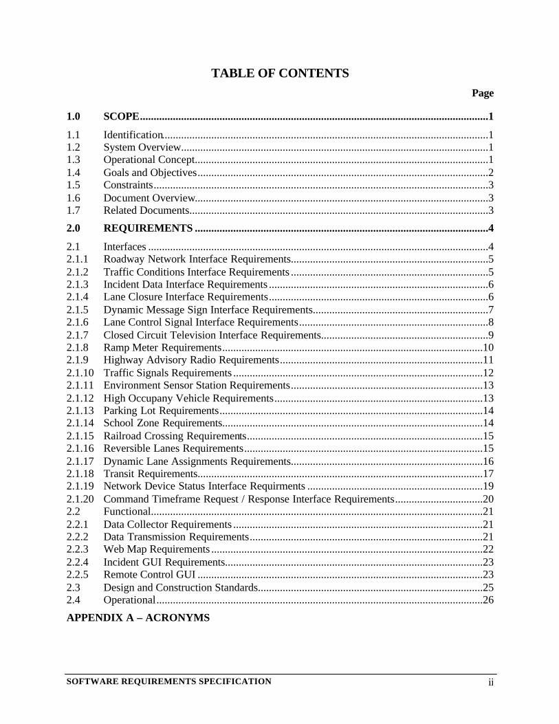
TABLE OF CONTENTSPage
1.0 SCOPE...............................................................................................................................1
1.1 Identification.......................................................................................................................11.2 System Overview................................................................................................................11.3 Operational Concept...........................................................................................................11.4 Goals and Objectives..........................................................................................................21.5 Constraints..........................................................................................................................31.6 Document Overview...........................................................................................................31.7 Related Documents.............................................................................................................3
2.0 REQUIREMENTS ...........................................................................................................4
2.1 Interfaces ............................................................................................................................42.1.1 Roadway Network Interface Requirements........................................................................52.1.2 Traffic Conditions Interface Requirements ........................................................................52.1.3 Incident Data Interface Requirements ................................................................................62.1.4 Lane Closure Interface Requirements................................................................................62.1.5 Dynamic Message Sign Interface Requirements................................................................72.1.6 Lane Control Signal Interface Requirements.....................................................................82.1.7 Closed Circuit Television Interface Requirements.............................................................92.1.8 Ramp Meter Requirements...............................................................................................102.1.9 Highway Advisory Radio Requirements..........................................................................112.1.10 Traffic Signals Requirements ...........................................................................................122.1.11 Environment Sensor Station Requirements......................................................................132.1.12 High Occupany Vehicle Requirements............................................................................132.1.13 Parking Lot Requirements................................................................................................142.1.14 School Zone Requirements...............................................................................................142.1.15 Railroad Crossing Requirements......................................................................................152.1.16 Reversible Lanes Requirements.......................................................................................152.1.17 Dynamic Lane Assignments Requirements......................................................................162.1.18 Transit Requirements........................................................................................................172.1.19 Network Device Status Interface Requirments ................................................................192.1.20 Command Timeframe Request / Response Interface Requirements................................202.2 Functional.........................................................................................................................212.2.1 Data Collector Requirements ...........................................................................................212.2.2 Data Transmission Requirements.....................................................................................212.2.3 Web Map Requirements ...................................................................................................222.2.4 Incident GUI Requirements..............................................................................................232.2.5 Remote Control GUI ........................................................................................................232.3 Design and Construction Standards..................................................................................252.4 Operational.......................................................................................................................26
APPENDIX A – ACRONYMS

SOFTWARE REQUIREMENTS SPECIFICATION iii
LIST OF TABLESPage
Table 1. Roadway Network Interface Requirements......................................................................5Table 2. Traffic Conditions Interface Requirements ......................................................................6Table 3. Incident Data Interface Requirements ..............................................................................6Table 4. Lane Closure Interface Requirements...............................................................................7Table 5. DMS Interface Requirements ...........................................................................................8Table 6. LCS Interface Requirements.............................................................................................9Table 7. CCTV Interface Requirements .......................................................................................10Table 8. Ramp Meter Interface Requirements..............................................................................11Table 9. HAR Interface Requirements..........................................................................................12Table 10. Traffic Signals Interface Requirements ........................................................................13Table 11. ESS Interface Requirements .........................................................................................13Table 12. HOV Interface Requirements .......................................................................................14Table 13. Parking Lot Interface Requirements .............................................................................14Table 14. School Zone Interface Requirements............................................................................15Table 15. Railroad Crossing Interface Requirements ...................................................................15Table 16. Reversible Lanes Interface Requirements ....................................................................16Table 17. Dynamic Lane Assignments Interface Requirements...................................................17Table 18. Transit Interface Requirements.....................................................................................18Table 19. Network Device Status Requirements ..........................................................................20Table 20. Command Timeframe Request / Response Interface Requirements ............................21Table 21. Data Collector Requirements........................................................................................21Table 22. Data Transmission Requirements .................................................................................21Table 23. WWW Map Requirements............................................................................................22Table 24. Incident GUI Requirements ..........................................................................................23Table 25. Remote Control GUI.....................................................................................................24Table 26. Computer Resource Requirements ...............................................................................25Table 27. Design and Implementation Requirements...................................................................26Table 28. Required States and Modes Requirements ...................................................................26

SOFTWARE REQUIREMENTS SPECIFICATION iv
REVISION HISTORY
Revision Date Changes1.0 September 4, 1999 Initial release2.0 February 24, 2000 • Significantly modified the structure of the SRS
• Requirements from version 1.0 were reformatted to utilizethe new structure
• Expanded the requirements for device status• Added requirements for device command/control• Added requirements for remote control user interface
3.0 December 5, 2001 Added EO-22 to identification table.Revised to reflect changes from SICD and CICD version 2.3.Incorporated input from DFW Regional Software Task Forceinto document. Major new additions included:• Ramp Meters• Highway Advisory Radio (HAR)• Traffic Signals• Environmental Sensor Stations (ESS)• High Occupancy Vehicle (HOV) Lanes• Parking Lots• School Zones• Railroad Crossings• Reversible Lanes• Dynamic Lanes• Transit

SOFTWARE REQUIREMENTS SPECIFICATION 1
1.0 SCOPE
This Software Requirements Specification (SRS) provides the requirements for the Center-to-Center Communications (C2C) Communications project.
1.1 Identification
Project Title: Center-To-Center Communications
Project Number: 04594, EO 1704594, EO 22
Abbreviation: C2CVersion Number: 3.0Release Number: 1
1.2 System Overview
This document describes the requirements for the Dallas/Ft. Worth (DFW) Regional “Center-to-Center (C2C) Communications Network” that is based on a Texas Department of Transportation(TxDOT) C2C project. The TxDOT C2c project initially connected the DFW TxDOT TrafficManagement Centers (TMCs). This C2C infrastructure implements a repository for traffic dataand provides a mechanism to exchange device control information between TMCs.
The C2C project will be implemented using the evolving ITS Traffic Management DataDictionary (TMDD) standard, the message sets associated with TMDD, other ITS Data Elementsand Message Sets. The use of ITS standards will create a system that is reusable for other ITSapplication areas and will provide the State of Texas with a baseline system that can be costeffectively extended in the future.
1.3 Operational Concept
The C2C infrastructure must interconnect several dissimilar traffic management systems. Inorder to create the C2C infrastructure, interfaces to the existing systems will be created. Thedata from these interfaces will communicate with the existing system in a “system specific”format. The data being deposited into the C2C infrastructure will be converted to a standardformat (based on the ITS standards). The C2C infrastructure is being created using a series ofbuilding blocks. These building blocks allow the software to be utilized in a number ofconfigurations (by simply altering the configuration parameters of the software).
In a region such as Dallas/Ft. Worth, multiple instances of the building blocks will be utilized.The software is being designed so that multiple instances of a building block can be deployed bysimply “configuring” the building block of operation within a specific agency. Conceptually, theC2C infrastructure would be deployed as depicted in the following diagram:

SOFTWARE REQUIREMENTS SPECIFICATION 2
Any data that is passed into the “cloud” in the above figure will be based on the ITS standards.Systems will interface to the “cloud” using a project defined protocol. New systems that aredeployed (based on the ITS standards) will not utilize the project defined protocol but will bemoved “into” the cloud (because they themselves would be based on the ITS standards.
1.4 Goals and Objectives
The C2C project has the following goals:
• To provide a common repository for traffic information for the DFW Metroplex.
• To provide a World Wide Web based graphical map to display traffic conditions in theDFW Metroplex.
• To provide a Microsoft Windows application that will allow agencies without a formalTraffic Management Center (TMC) to participate in the C2C infrastructure andinformation sharing.
• To provide a system which supports ITS center-to-center communications forcommand/control/status of various ITS field devices including: Dynamic MessageSigns, Lane Control Signals and Closed Circuit Television Cameras (CCTVs), RampMeters, and Highway Advisory Radios (HARs).
• To utilize National ITS standards to implement the project.
• To provide a software system that is extensible all local or regional partners. Thiswould allow a “local” common repository to be created by “linking” individualpartners, a “regional” common repository to be created by “linking” local commonrepositories and a “statewide” common repository to be created by “linking” regionalcommon repositories.
SOFTWARE REQUIREMENTS SPECIFICATION 3
1.5 Constraints
None.
1.6 Document Overview
Section 2 defines the requirements of the system. Acronyms are defined in Appendix A.
1.7 Related Documents
• Concept Of Operations Framework For The Dallas/Ft. Worth Regional Center-to-CenterCommunications Network, Version 1.0, Southwest Research Institute, November 2001.
SOFTWARE REQUIREMENTS SPECIFICATION 4
2.0 REQUIREMENTS
The following sections define the requirements for the C2C project. Requirements are listed inseparate sections and in table format for each functional area. The C2C project mnemonicuniquely identifies the C2C project to distinguish its requirements from the requirements of otherITS systems. The mnemonic for the C2C project is C2C. The Requirement Category Mnemonicis a two-letter mnemonic for each functional area. The Requirement Numbers are a combinationof target Advanced Traffic Management System (ATMS) and sequential within a givenfunctional area.
The columns of the tables are structured as follows:
• The first column of the table contains the requirement identifier. The requirementidentifier is a three-part number that is used to uniquely identify each requirement. Thenumber consists of the following fields: <C2C Project Mnemonic>-<RequirementCategory Mnemonic>-<Requirement Number>.
• The second column of each table contains a description of the requirement.
• The third column contains a rationale for the requirements. If the rationale is left blankfor a particular requirement, the requirement rationale is assumed obvious from thedescription.
2.1 Interfaces
The following tables list the interfaces that shall be developed.
SOFTWARE REQUIREMENTS SPECIFICATION 5
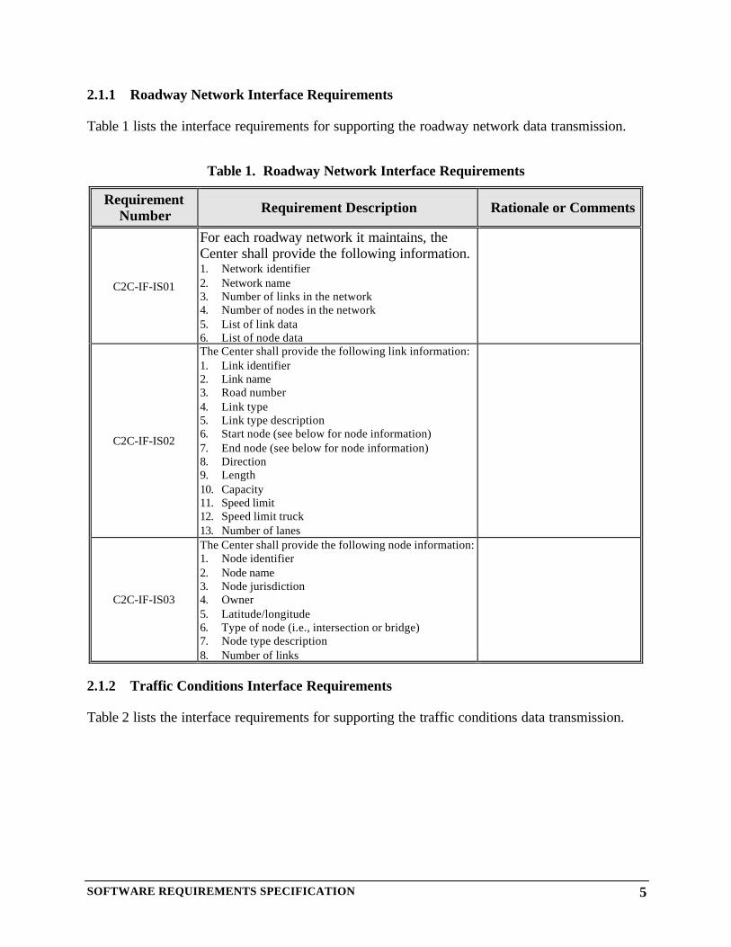
2.1.1 Roadway Network Interface Requirements
Table 1 lists the interface requirements for supporting the roadway network data transmission.
Table 1. Roadway Network Interface Requirements
RequirementNumber Requirement Description Rationale or Comments
C2C-IF-IS01
For each roadway network it maintains, theCenter shall provide the following information.1. Network identifier2. Network name3. Number of links in the network4. Number of nodes in the network5. List of link data6. List of node data
C2C-IF-IS02
The Center shall provide the following link information:1. Link identifier2. Link name3. Road number4. Link type5. Link type description6. Start node (see below for node information)7. End node (see below for node information)8. Direction9. Length10. Capacity11. Speed limit12. Speed limit truck13. Number of lanes
C2C-IF-IS03
The Center shall provide the following node information:1. Node identifier2. Node name3. Node jurisdiction4. Owner5. Latitude/longitude6. Type of node (i.e., intersection or bridge)7. Node type description8. Number of links
2.1.2 Traffic Conditions Interface Requirements
Table 2 lists the interface requirements for supporting the traffic conditions data transmission.

SOFTWARE REQUIREMENTS SPECIFICATION 6
Table 2. Traffic Conditions Interface Requirements
RequirementNumber
Requirement Description Rationale or Comments
C2C-IF-IS04
For each link defined within the Center:1. Network identifier2. Link identifier3. Data type4. Data type description5. Delay6. Travel time7. Volume8. Speed9. Density10. Occupancy
2.1.3 Incident Data Interface Requirements
Table 3 lists the interface requirements for supporting the incident data transmission.
Table 3. Incident Data Interface Requirements
RequirementNumber
Requirement Description Rationale or Comments
C2C-IF-IS05
The Center shall support the following information abouteach incident:1. Network identifier2. Incident ID3. Incident description4. Roadway5. Cross street6. Latitude/longitude7. Link identifier8. Direction9. Status10. Update Type11. Affected lanes12. Classification13. Severity14. Incident type15. Incident type description16. Road conditions17. Weather18. Confirmed date & time19. Cleared date & time
2.1.4 Lane Closure Interface Requirements
Table 4 lists the interface requirements for supporting the lane closure data transmission.
SOFTWARE REQUIREMENTS SPECIFICATION 7
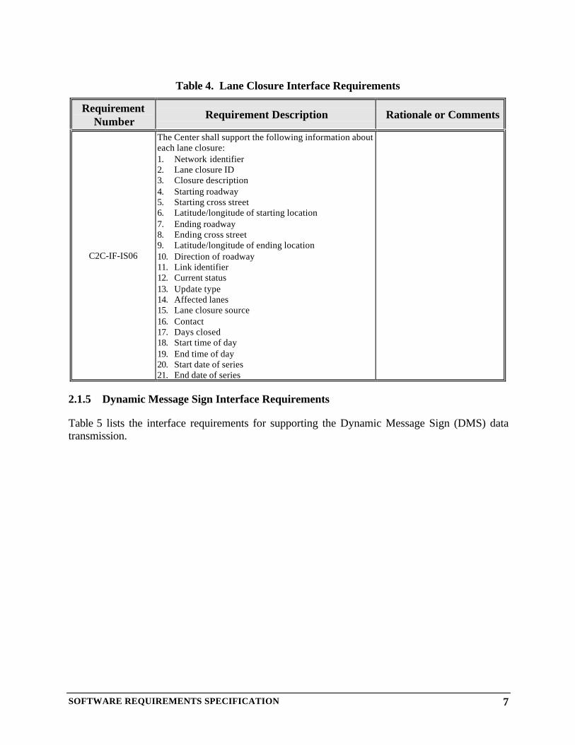
Table 4. Lane Closure Interface Requirements
RequirementNumber
Requirement Description Rationale or Comments
C2C-IF-IS06
The Center shall support the following information abouteach lane closure:1. Network identifier2. Lane closure ID3. Closure description4. Starting roadway5. Starting cross street6. Latitude/longitude of starting location7. Ending roadway8. Ending cross street9. Latitude/longitude of ending location10. Direction of roadway11. Link identifier12. Current status13. Update type14. Affected lanes15. Lane closure source16. Contact17. Days closed18. Start time of day19. End time of day20. Start date of series21. End date of series
2.1.5 Dynamic Message Sign Interface Requirements
Table 5 lists the interface requirements for supporting the Dynamic Message Sign (DMS) datatransmission.

SOFTWARE REQUIREMENTS SPECIFICATION 8
Table 5. DMS Interface Requirements
RequirementNumber
Requirement Description Rationale or Comments
C2C-IF-IS07
The Center shall provide the following status informationabout each DMS:1. Network Identifier2. DMS Identifier3. DMS Name4. Location (latitude/longitude)5. Sign Geometry (row/column)6. Status (online/offline)7. Current message (MULTI string)8. Beacons (on/off)
C2C-IF-IS08
To support DMS control in other centers, the Center shallbe able to support the following device control commandfor a DMS:1. Network identifier2. DMS Identifier3. Username4. Password5. Beacons (on/off)6. Immediate message (MULTI string)
2.1.6 Lane Control Signal Interface Requirements
Table 6 lists the interface requirements for supporting the Lane Control Signal (LCS) datatransmission.
SOFTWARE REQUIREMENTS SPECIFICATION 9
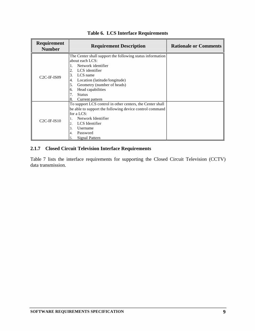
Table 6. LCS Interface Requirements
RequirementNumber
Requirement Description Rationale or Comments
C2C-IF-IS09
The Center shall support the following status informationabout each LCS:1. Network identifier2. LCS identifier3. LCS name4. Location (latitude/longitude)5. Geometry (number of heads)6. Head capabilities7. Status8. Current pattern
C2C-IF-IS10
To support LCS control in other centers, the Center shallbe able to support the following device control commandfor a LCS:1. Network Identifier2. LCS Identifier3. Username4. Password5. Signal Pattern
2.1.7 Closed Circuit Television Interface Requirements
Table 7 lists the interface requirements for supporting the Closed Circuit Television (CCTV)data transmission.

SOFTWARE REQUIREMENTS SPECIFICATION 10
Table 7. CCTV Interface Requirements
RequirementNumber
Requirement Description Rationale or Comments
C2C-IF-IS11
The Center shall provide the following information statusinformation about each CCTV:1. Network identifier2. CCTV identifier3. CCTV name4. Location (latitude/longitude)5. Status (online/offline)6. Locked/unlocked7. Lock holder (if locked)8. Supported directions9. Current direction10. Current preset position11. Current pan12. Current tilt13. Current zoom14. Current focus15. Current iris
C2C-IF-IS12
To support CCTV control in other centers, the Centershall be able to support the following CCTV controlrequest:1. Network identifier2. CCTV Identifier3. Username4. Password5. CCTV request (one of the following):§ Lock camera§ Set direction§ Set preset§ Set absolute (pan/tilt/zoom/focus/iris)§ Stop offset (pan/tilt/zoom/focus/iris)
Ft. Worth will not supportMomentaryPan/Tilt/Zoom/Iris/Focuscommand
C2C-IF-IS13
To support video snapshots, the Center shall be able tosupport the following status information:1. Network identifier2. CCTV Identifier3. CCTV Name4. Status5. Current camera direction6. Size of snapshot7. Video snapshot (in JPEG format)
C2C-IF-IS14
To support CCTV switching in other centers, the Centershall be able to support the following CCTV switchingcommand:1. Network identifier (owner of CCTV)2. Username3. Password4. Video channel input identifier5. Video channel output identifier
Dallas will not support the Tourvideo switch command
2.1.8 Ramp Meter Requirements
Table 8 lists the interface requirements for supporting the ramp meter data transmission.
SOFTWARE REQUIREMENTS SPECIFICATION 11
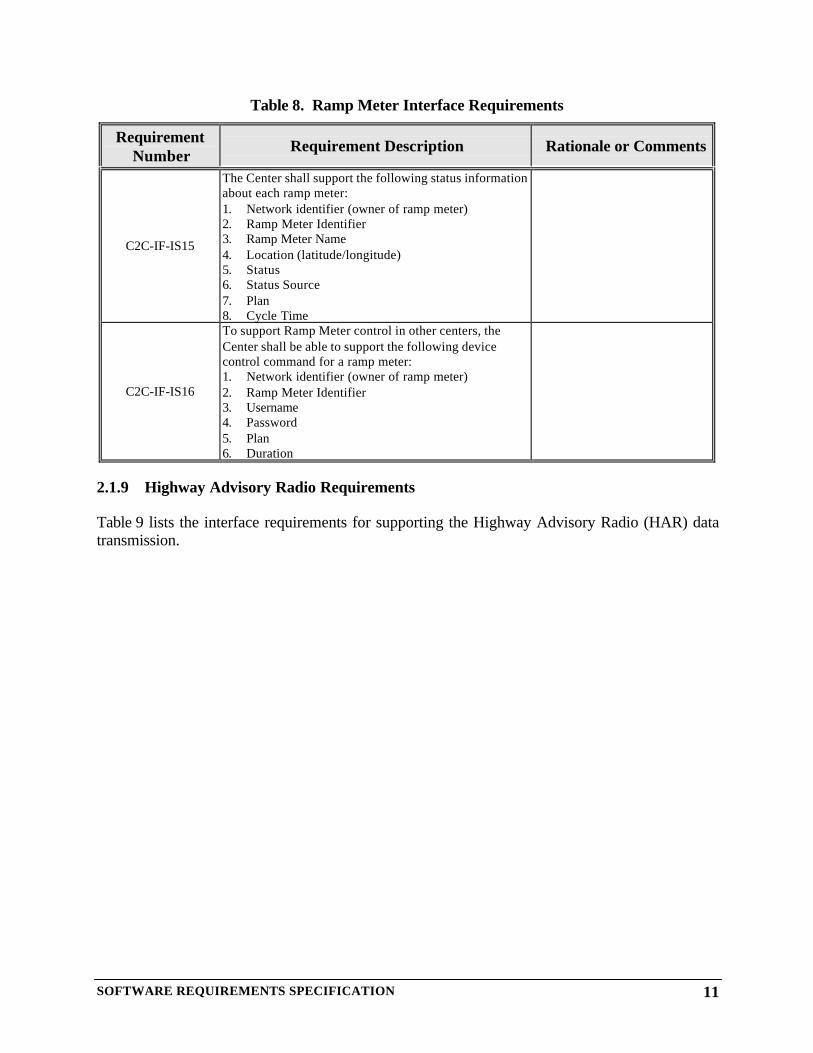
Table 8. Ramp Meter Interface Requirements
RequirementNumber
Requirement Description Rationale or Comments
C2C-IF-IS15
The Center shall support the following status informationabout each ramp meter:1. Network identifier (owner of ramp meter)2. Ramp Meter Identifier3. Ramp Meter Name4. Location (latitude/longitude)5. Status6. Status Source7. Plan8. Cycle Time
C2C-IF-IS16
To support Ramp Meter control in other centers, theCenter shall be able to support the following devicecontrol command for a ramp meter:1. Network identifier (owner of ramp meter)2. Ramp Meter Identifier3. Username4. Password5. Plan6. Duration
2.1.9 Highway Advisory Radio Requirements
Table 9 lists the interface requirements for supporting the Highway Advisory Radio (HAR) datatransmission.

SOFTWARE REQUIREMENTS SPECIFICATION 12
Table 9. HAR Interface Requirements
RequirementNumber
Requirement Description Rationale or Comments
C2C-IF-IS17
The Center shall support the following status informationabout each HAR:1. Network identifier (owner of HAR)2. HAR Identifier3. HAR Name4. Location (latitude/longitude)5. Status6. Current Message7. Current Message Text
C2C-IF-IS18
To support HAR control in other centers, the Center shallbe able to support the following device control commandfor a HAR:1. Network identifier (owner of HAR)2. HAR Identifier3. Username4. Password5. Message6. Message Text7. Duration
2.1.10 Traffic Signals Requirements
Table 10 lists the interface requirements for supporting the Traffic Signals data transmission.
SOFTWARE REQUIREMENTS SPECIFICATION 13
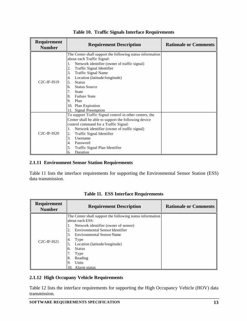
Table 10. Traffic Signals Interface Requirements
RequirementNumber
Requirement Description Rationale or Comments
C2C-IF-IS19
The Center shall support the following status informationabout each Traffic Signal:1. Network identifier (owner of traffic signal)2. Traffic Signal Identifier3. Traffic Signal Name4. Location (latitude/longitude)5. Status6. Status Source7. State8. Failure State9. Plan10. Plan Expiration11. Signal Preemption
C2C-IF-IS20
To support Traffic Signal control in other centers, theCenter shall be able to support the following devicecontrol command for a Traffic Signal:1. Network identifier (owner of traffic signal)2. Traffic Signal Identifier3. Username4. Password5. Traffic Signal Plan Identifier6. Duration
2.1.11 Environment Sensor Station Requirements
Table 11 lists the interface requirements for supporting the Environmental Sensor Station (ESS)data transmission.
Table 11. ESS Interface Requirements
RequirementNumber
Requirement Description Rationale or Comments
C2C-IF-IS21
The Center shall support the following status informationabout each ESS:1. Network identifier (owner of sensor)2. Environmental Sensor Identifier3. Environmental Sensor Name4. Type5. Location (latitude/longitude)6. Status7. Type8. Reading9. Units10. Alarm status
2.1.12 High Occupany Vehicle Requirements
Table 12 lists the interface requirements for supporting the High Occupancy Vehicle (HOV) datatransmission.

SOFTWARE REQUIREMENTS SPECIFICATION 14
Table 12. HOV Interface Requirements
RequirementNumber
Requirement Description Rationale or Comments
C2C-IF-IS22
The Center shall support the following status informationabout each HOV:1. Network identifier (owner of HOV)2. HOV Identifier3. HOV Name4. Link Identifier5. Status6. Failure State7. Plan8. State9. Status Source10. Occupants11. Next Transition Time
C2C-IF-IS22.1
To support HOV Lane control in other centers, theCenter shall be able to support the following devicecontrol command for a HOV Lane:1. Network identifier (owner of HOV)2. HOV Lane Identifier3. Username4. Password5. Lane Plan6. Duration
2.1.13 Parking Lot Requirements
Table 13 lists the interface requirements for supporting the Parking Lot data transmission.
Table 13. Parking Lot Interface Requirements
RequirementNumber
Requirement Description Rationale or Comments
C2C-IF-IS23
The Center shall support the following status informationabout each Parking Lot:1. Network identifier (owner of parking lot)2. Parking Lot Identifier3. Parking Lot Name4. Location (latitude/longitude)5. Status6. Capacity7. Utilization8. Entrance9. Restrictions10. Special Capabilities
2.1.14 School Zone Requirements
Table 14 lists the interface requirements for supporting the School Zone data transmission.

SOFTWARE REQUIREMENTS SPECIFICATION 15
Table 14. School Zone Interface Requirements
RequirementNumber
Requirement Description Rationale or Comments
C2C-IF-IS24
The Center shall support the following status informationabout each School Zone:1. Network identifier (owner of school zone)2. Link Identifier3. School Zone Identifier4. School Zone Name5. Location (latitude/longitude)6. Status7. Failure Status8. State Plan9. State Source
C2C-IF-IS25
To support School Zone control in other centers, theCenter shall be able to support the following devicecontrol command for a School Zone:1. Network identifier (owner of school zone)2. School Zone Identifier3. Username4. Password5. Plan
2.1.15 Railroad Crossing Requirements
Table 15 lists the interface requirements for supporting the Railroad Crossing data transmission.
Table 15. Railroad Crossing Interface Requirements
RequirementNumber
Requirement Description Rationale or Comments
C2C-IF-IS26
The Center shall support the following status informationabout each Railroad Crossing:1. Network identifier (owner of railroad Crossing)2. Link Identifier3. Rail Crossing Identifier4. Rail Crossing Name5. Location (latitude/longitude)6. Status7. Rail Type8. Estimated Time for Train to Clear of Intersection9. Estimated Minutes to Train Arrival10. Rail closing signal type
2.1.16 Reversible Lanes Requirements
Table 16 lists the interface requirements for supporting the Reversible Lanes data transmission.

SOFTWARE REQUIREMENTS SPECIFICATION 16
Table 16. Reversible Lanes Interface Requirements
RequirementNumber
Requirement Description Rationale or Comments
C2C-IF-IS27
The Center shall support the following status informationabout each Reversible Lane:1. Network identifier (owner of reversible lane)2. Reversible Lane Identifier3. Reversible Lane Name4. Link Identifier5. Indicator Status6. Indicator Failure State7. Plan8. Direction9. Direction Transition Time10. Status Source
C2C-IF-IS28
To support Reversible Lane control in other centers, theCenter shall be able to support the following devicecontrol command for a Reversible Lane:1. Network identifier (owner of reversible lane)2. Reversible Lane Identifier3. Username4. Password5. Plan6. Duration
2.1.17 Dynamic Lane Assignments Requirements
Table 17 lists the interface requirements for supporting the Dynamic Lane Assignment datatransmission.

SOFTWARE REQUIREMENTS SPECIFICATION 17
Table 17. Dynamic Lane Assignments Interface Requirements
RequirementNumber
Requirement Description Rationale or Comments
C2C-IF-IS29
The Center shall support the following status informationabout each Dynamic Lane:1. Network identifier (owner of dynamic lane)2. Link Identifier3. Dynamic Lane Identifier4. Dynamic Lane Name5. Indicator Status6. Failure State7. Plan8. Type9. Transition Time
C2C-IF-IS30
To support Dynamic Lane control in other centers, theCenter shall be able to support the following devicecontrol command for a Dynamic Lane:1. Network identifier (owner of dynamic lane)2. Dynamic Lane Identifier3. Username4. Password5. Lane Plan6. Duration
2.1.18 Transit Requirements
Table 18 lists the interface requirements for supporting the Transit data transmission.

SOFTWARE REQUIREMENTS SPECIFICATION 18
Table 18. Transit Interface Requirements
RequirementNumber
Requirement Description Rationale or Comments
C2C-IF-IS30
The Center shall support the following status informationabout each Bus Stop:1. Network identifier (owner of bus stop)2. Link Identifier1
3. Relative Link Location4. Identifier5. Name6. Location (Node)7. Bus Routes8. Frequency
C2C-IF-IS31
The Center shall support the following status informationabout each Bus Location:1. Network identifier (owner of bus)2. Link Identifier3. Bus Identifier4. Bus Name5. Location (latitude/longitude)6. Schedule Adherence7. Vehicle Attributes8. Capacity
C2C-IF-IS32
The Center shall support the following status informationabout each Light/Commuter Stop:1. Network identifier (owner of stop)2. Link Identifier3. Commuter / Light Rail Stop Identifier4. Commuter / Light Rail Stop Name5. Location6. Routes7. Frequency
C2C-IF-IS33
The Center shall support the following status informationabout each Light/Commuter Location:1. Network identifier (owner of train)2. Link Identifier3. Commuter / Light Rail Identifier4. Commuter / Light Rail Name5. Location (latitude/location)6. Schedule Adherence7. Vehicle Attributes8. Capacity
1 Associating a bus stop, commuter / light rail stop, bus location, etc. with a link within a roadway network may bean inherently difficult problem from a configuration management perspective. The roadway network and transitinformation may be managed by separate centers, i.e. City of Dallas vs. DART. Updates to the roadway network,i.e. renaming links, may cause the associated link information within the transit data to become outdated andinconsistent with the location data.

SOFTWARE REQUIREMENTS SPECIFICATION 19
RequirementNumber
Requirement Description Rationale or Comments
C2C-IF-IS34
The Center shall support the following status informationabout each Park and Ride Lot:1. Network identifier (owner of lot)2. Park and Ride Lot Identifier3. Park and Ride Lot Name4. Location (latitude/location)5. Status6. Capacity7. Utilization8. Entrance9. Restrictions10. Special Capabilities
C2C-IF-IS35
The Center shall support the following status informationabout each Vehicle Priority:1. Vehicle Identifier2. Network identifier (owner of signal)3. Link Identifier4. Intersection Identifier5. Priority Request Status6. Departure Time7. Desired Arrival Time8. Priority9. Vehicle Classification10. Service Strategy
2.1.19 Network Device Status Interface Requirments
Table 19 lists the interface requirements for supporting network device status data transmission.

SOFTWARE REQUIREMENTS SPECIFICATION 20
Table 19. Network Device Status Requirements
RequirementNumber
Requirement Description Rationale or Comments
C2C-IF-IS36
The Center shall support the following information aboutnetwork device status:1. Network identifier2. Number of DMSs3. Number of LCSs4. Number of CCTVs5. Number of CCTV video inputs6. Number of CCTV video outputs7. Number of Ramp Meters8. Number of HARs9. Number of Traffic Signals10. Number of ESSs11. Number of HOVs12. Number of Parking Lots13. Number of School Zones14. Number of Railroad Crossings15. Number of Reversible Lanes16. Number of Dynamic Lanes17. DMS status data18. LCS status data19. CCTV status data20. Video input channel identifiers21. Video output channel identifiers22. Ramp Meter status data23. HAR status data24. Traffic Signal status data25. ESS status data26. HOV status data27. Parking Lot status data28. School Zone status data29. Railroad Crossing status data30. Reversible Lane status data31. Dynamic Lane status data
2.1.20 Command Timeframe Request / Response Interface Requirements
Table 20 lists the interface requirements supporting command timeframe requests and responses.
SOFTWARE REQUIREMENTS SPECIFICATION 21
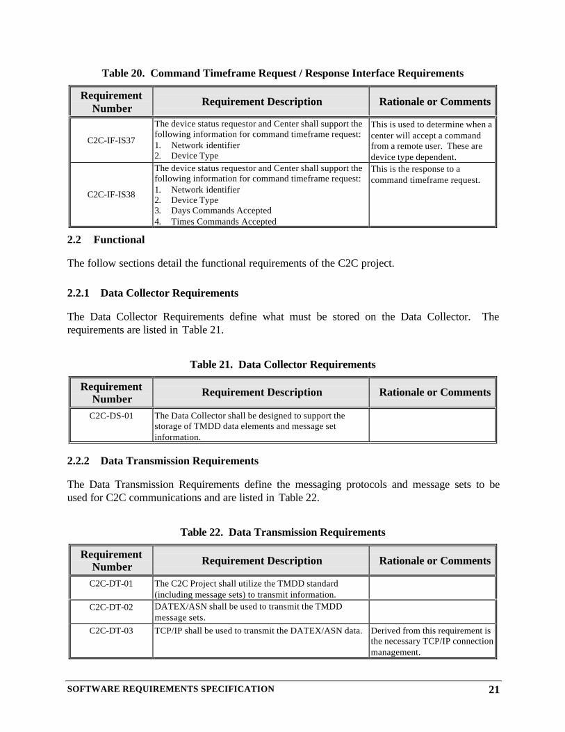
Table 20. Command Timeframe Request / Response Interface Requirements
RequirementNumber
Requirement Description Rationale or Comments
C2C-IF-IS37
The device status requestor and Center shall support thefollowing information for command timeframe request:1. Network identifier2. Device Type
This is used to determine when acenter will accept a commandfrom a remote user. These aredevice type dependent.
C2C-IF-IS38
The device status requestor and Center shall support thefollowing information for command timeframe request:1. Network identifier2. Device Type3. Days Commands Accepted4. Times Commands Accepted
This is the response to acommand timeframe request.
2.2 Functional
The follow sections detail the functional requirements of the C2C project.
2.2.1 Data Collector Requirements
The Data Collector Requirements define what must be stored on the Data Collector. Therequirements are listed in Table 21.
Table 21. Data Collector Requirements
RequirementNumber
Requirement Description Rationale or Comments
C2C-DS-01 The Data Collector shall be designed to support thestorage of TMDD data elements and message setinformation.
2.2.2 Data Transmission Requirements
The Data Transmission Requirements define the messaging protocols and message sets to beused for C2C communications and are listed in Table 22.
Table 22. Data Transmission Requirements
RequirementNumber Requirement Description Rationale or Comments
C2C-DT-01 The C2C Project shall utilize the TMDD standard(including message sets) to transmit information.
C2C-DT-02 DATEX/ASN shall be used to transmit the TMDDmessage sets.
C2C-DT-03 TCP/IP shall be used to transmit the DATEX/ASN data. Derived from this requirement isthe necessary TCP/IP connectionmanagement.

SOFTWARE REQUIREMENTS SPECIFICATION 22
2.2.3 Web Map Requirements
The Web Map application generates a map that can be displayed on an Internet WWW server.The map provides a graphical depiction of the traffic conditions. The requirements for theWWW map are listed in Table 23.
Table 23. WWW Map Requirements
RequirementNumber
Requirement Description Rationale or Comments
C2C-MP-01 The map shall display interstates and state highways onthe graphical map.
C2C-MP-03 The basemap data shall be derived from the NorthCentral Texas Council of Governments (NCTCOG) Geo-Data warehouse.
C2C-MP-03 The map user shall be able to alter the currentmagnification (zoom level) of the map.
C2C-MP-04 The map user shall be able to pan the map in each of thefollowing directions: North, South, East or West.
C2C-MP-05 Each link displayed on the map shall be color coded toprovide a graphical depiction of speeds. A configurationfile shall be provided to specify specific speed values.The color coding shall be as follows:
• Green - speeds > TBD MPH• Yellow - speeds between TBD and TBD MPH• Red – speeds below TBD MPH
C2C-MP-06 The map shall display the current incidents (as icons)known to the C2C Project.
C2C-MP-07 The user shall be able to click on an incident icon toobtain further information about the incident.
C2C-MP-08 All current incidents shall be displayed in tabular formatwith the following information contained in the table:
• Location• Type of incident (e.g., accident, lane closure)• Severity of incident• Incident status• Travel direction• Effected lanes
C2C-MP-09 The map shall be capable of displaying the following fora DMS:1. Location2. Current Message
C2C-MP-10 The map shall be capable of displaying the following fora LCS:1. Location2. Current Signals
C2C-MP-11 The map shall be capable of displaying the following fora CCTV:1. Location2. Status

SOFTWARE REQUIREMENTS SPECIFICATION 23
2.2.4 Incident GUI Requirements
The Incident GUI must provide data to the C2C Infrastructure. The GUI requirements are listedin Table 24.
Table 24. Incident GUI Requirements
RequirementNumber
Requirement Description Rationale orComments
C2C-GI-01 The Incident GUI shall allow the user to enter incident or lane closureinformation without the use of an Center.
C2C-GI-02 The Incident GUI shall allow the user to input the followinginformation for each incident:
• Location (latitude/longitude)• Description• Status• Effected lanes• Detection time• Response time• Estimated time to clear queue• Queue length
C2C-GI-03 The Incident GUI shall allow the user to input the followinginformation for each lane closure:
• Location (latitude/longitude)• Description• Effected lanes• Date• Start time• End time
C2C-GI-04 The GUI shall provide a list of previously entered incidents.C2C-GI-05 The GUI shall allow the data about an incident to be modified.
C2C-GI-06 The GUI shall allow a user to delete a previously entered incident.
C2C-GI-07 The GUI shall provide a list of previously entered lane closures.
C2C-GI-08 The GUI shall allow a user to delete a previously entered lane closure.
C2C-GI-09 The GUI shall allow a user to delete a previously entered lane closure.
2.2.5 Remote Control GUI
Table 25 contains the requirements for the Remote Control GUI.

SOFTWARE REQUIREMENTS SPECIFICATION 24
Table 25. Remote Control GUI
RequirementNumber
Requirement Description Rationale or Comments
C2C-CG-01
The remote Center Control GUI shall be designed toexecute on a public network (e.g., Internet) and transmitequipment requests to the C-2-C software system.
The Remote Control GUI willexecute as a local application ona PC. The application willgenerate TMDD device controlmessages that will be sent to aCenter for processing.Connectivity through the variousfirewalls and gateways is notaddressed by this requirement.
C2C-CG-02
When the GUI application is initiated, the user shall beprompted for the following information:
• User name• Password
C2C-CG-03The user shall be provided with the capability to select anetwork identifier for a device command/control request.
C2C-CG-04
Once an Center is selected, the user shall be able to selecta DMS from a list and provide the following information:
• Target DMS• Message to be displayed• Beacons On/Off
C2C-CG-05
Once an Center is selected, the user shall be able to selecta LCS from a list and provide the following information:
• Target LCS• Assignment of lane arrows
C2C-CG-06
Once an Center is selected, the user shall be able to issuea CCTV switching command:
• Source (input)• Destination port (output)
C2C-CG-07
Once an Center is selected, the user shall be able to selecta CCTV from a list and provide the followinginformation:
• Target CCTV• Device control including:
• Pan• Tilt• Zoom
C2C-CG-08
Once an Center is selected, the user shall be able to selecta Ramp Meter from a list and provide the followinginformation:
• Target Ramp Meter• Plan
C2C-CG-09
Once an Center is selected, the user shall be able to selecta HAR from a list and provide the following information:
• Target HAR• Text to be sent to the HAR
C2C-CG-10
Once an Center is selected, the user shall be able to selecta Traffic Signal from a list and provide the followinginformation:
• Target Traffic Signal• Plan
C2C-CG-11 Once an Center is selected, the user shall be able to select

SOFTWARE REQUIREMENTS SPECIFICATION 25
RequirementNumber
Requirement Description Rationale or Comments
a HOV from a list and provide the following information:• Target HOV• Plan
C2C-CG-12
Once an Center is selected, the user shall be able to selecta School Zone from a list and provide the followinginformation:
• Target School Zone• Plan
C2C-CG-13
Once an Center is selected, the user shall be able to selecta Reversible Lane from a list and provide the followinginformation:
• Target Reversible Lane• Plan
C2C-CG-14
Once an Center is selected, the user shall be able to selecta Dynamic Lane from a list and provide the followinginformation:
• Target Dynamic Lane• Plan
C2C-CG-15For each device command/control status request sent bythe Remote GUI, the status returned from the networkidentifier will be displayed in a scrollable list on the GUI.
2.3 Design and Construction Standards
The computer resource requirements are listed in Table 26.
Table 26. Computer Resource Requirements
RequirementNumber
Requirement Description Rationale or Comments
C2C-DC-01 The C2C Server shall execute in a Microsoft WindowsNT environment.
C2C-DC-02 A DATEX/ASN runtime library shall be available on anycomputer communicating to the C2C project.
C2C-DC-03 The web server application shall use ESRI's ARCInternet Map Server (ARC IMS) product for creating ofmap images.
The Design and implementation requirements are listed in the in Table 27.

SOFTWARE REQUIREMENTS SPECIFICATION 26
Table 27. Design and Implementation Requirements
RequirementNumber
Requirement Description Rationale or Comments
C2C-DC-04 The C2C shall execute in a Microsoft Windows NTenvironment.
C2C-DC-05 The C2C shall be implemented in the C/C++programming language.
C2C-DC-06 The C2C web interface shall be implemented usingC/C++ and ESRI ARC IMS.
C2C-DC-07 The Incident GUI shall be implemented using C/C++ andESRI Map Objects.
C2C-DC-08 The Remote Control GUI shall be implemented usingC/C++ and ESRI Map Objects.
2.4 Operational
The C2C Project shall be capable of operating in one of two modes: normal mode for normaloperations or in test mode for development and testing. The requirements for these modes arelisted in Table 28.
Table 28. Required States and Modes Requirements
RequirementNumber Requirement Description Rationale or Comments
C2C-OP-01 The C2C shall be able to operate in normal mode. In thismode the C2C receives data from all connected systems,including the Incident GUI, and combines the data into asingle data store (database).
C2C-OP-02 The C2C shall be able to operate in test mode. In thismode, the C2C performs normal mode operations andalso logs activities.
To provide additionalinformation for development andtesting.
SOFTWARE REQUIREMENTS SPECIFICATION
APPENDIX A
ACRONYMS
SOFTWARE REQUIREMENTS SPECIFICATION A-1
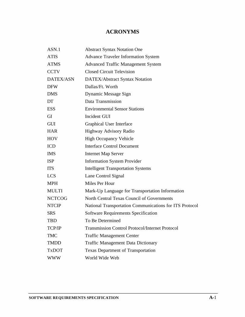
ACRONYMS
ASN.1 Abstract Syntax Notation OneATIS Advance Traveler Information System
ATMS Advanced Traffic Management System
CCTV Closed Circuit Television
DATEX/ASN DATEX/Abstract Syntax Notation
DFW Dallas/Ft. WorthDMS Dynamic Message Sign
DT Data Transmission
ESS Environmental Sensor Stations
GI Incident GUI
GUI Graphical User InterfaceHAR Highway Advisory Radio
HOV High Occupancy Vehicle
ICD Interface Control Document
IMS Internet Map Server
ISP Information System ProviderITS Intelligent Transportation Systems
LCS Lane Control Signal
MPH Miles Per Hour
MULTI Mark-Up Language for Transportation Information
NCTCOG North Central Texas Council of GovernmentsNTCIP National Transportation Communications for ITS Protocol
SRS Software Requirements Specification
TBD To Be Determined
TCP/IP Transmission Control Protocol/Internet Protocol
TMC Traffic Management CenterTMDD Traffic Management Data Dictionary
TxDOT Texas Department of Transportation
WWW World Wide Web