software requirements specification (srs) ankaya university faculty of engineering computer...
TRANSCRIPT
ÇANKAYA UNIVERSITY
FACULTY OF ENGINEERING
COMPUTER ENGINEERING DEPARMENT
CENG 407
SOFTWARE REQUIREMENTS SPECIFICATION
(SRS)
DETECTION OF OBSTRUCTIONS IN THE VESSELS IN
FUNDUS IMAGES
By
201311018 - AYKUT ER
201411045 - EGEBERK ÖZBERK
Fall, 2017-2018

2
Table of Contents
LIST OF FIGURES................................................................................................................................4
LIST OF TABLES..................................................................................................................................4
1. INTRODUCTION ..............................................................................................................................5
1.1 Purpose ...........................................................................................................................................5
1.2 Scope of Project ..............................................................................................................................5
1.2.1 Benefits....................................................................................................................................5
1.3 Glossary ..........................................................................................................................................5
1.4 References ......................................................................................................................................6
1.5 Overview of the Document ............................................................................................................6
2. OVERALL DESCRIPTION .............................................................................................................6
2.1 Product Perspective ........................................................................................................................6
2.3 User Characteristics ........................................................................................................................6
2.3 Constraints ......................................................................................................................................6
2.4 Risks ...............................................................................................................................................7
2.5 Assumptions ...................................................................................................................................7
3. REQUIREMENTS .............................................................................................................................7
3.1 Specific Requirements ...................................................................................................................7
3.1.1 User Interfaces .........................................................................................................................7
3.1.2 Hardware Interfaces ................................................................................................................7
3.1.3 Software Interfaces ..................................................................................................................7
3.1.4 Communications Interfaces .....................................................................................................7
3.2 Functional Requirements ................................................................................................................7
3.3 Software System Attributes ............................................................................................................8
3.3.1 Performance ............................................................................................................................8
3.3.2 Availability ..............................................................................................................................8
3.3.3 Security....................................................................................................................................8
3.3.4 Portability ................................................................................................................................8
3.3.5 Usability .................................................................................................................................8
3.3.6 Scalability ................................................................................................................................8
3.3.7 Ease of Use ..............................................................................................................................8
4. UML ANALYSIS MODEL ..............................................................................................................8
4.1 Use Cases .......................................................................................................................................8
4.1.1 Actors ......................................................................................................................................8
4.1.2 Stakeholders ............................................................................................................................9

3
4.1.3 Use Case Diagram ...................................................................................................................9
4.1.3.1 Brief Description of Use Case Diagram ........................................................................10
4.1.4 Use Case Descriptions ...........................................................................................................11
4.2 State chart Diagrams .....................................................................................................................13
5. REFERENCES ................................................................................................................................13
4
List of Figures
Figure 4.1.1. Obstruction Detection System Use Case Diagram ............................................................10
Figure 4.2.1. Obstruction Detection System State Chart Diagram .........................................................13
List of Tables
Table 1.3.1. Glossary of SRS ...................................................................................................................5
Table 4.1.1. Upload Image Use Case Description ..................................................................................11
Table 4.1.2. Click Find Congestion Button Use Case Description ........................................................11
Table 4.1.3. Customize Markings Use Case Description .......................................................................12
Table 4.1.4. Save Results Use Case Description ....................................................................................12

5
1. INTRODUCTION
This document provides detailed information about the requirements of obstructions detection
system software. It will explain the purpose and features of the proposed method, the working
principles of this method and the general information about the difference of the proposed
method from previous studies. This document is intended for both stakeholders and
developers who are working on such work.
1.1 Purpose
This project's main purpose is to find congestions inside vessels in eye angiographic images
therefore, primary objective is to reduce the effort spent by the doctor to detect eye diseases.
The main motivation for the ophthalmologist to use this software is to allow the software to
interpret the image much more quickly with immense accuracy and precision to reduce the
time spent on a single patient so that the doctor can deal with more patients in the same time.
1.2 Scope of the Project
This software system will be an Obstruction Detection System for an ophthalmologist. This
system will be designed to maximize the ophthalmologist’s productivity by providing tools to
assist in automating the congestion detection process inside retinal vessels, which would
otherwise have to be performed manually. By maximizing the ophthalmologist’s work
efficiency and production the system will meet the ophthalmologist’s needs while remaining
easy to understand and use. More specifically, the system is designed to automatically identify
obstructions however, in case of any possible error, the ophthalmologist is also asked to
provide a feedback about the congestion spots that system has already found.
1.2.1 Benefits
Thanks to this software, the ophthalmologist can diagnose multiple patients in the time
needed to diagnose a single patient. In addition, early and more accurate diagnosis will
prevent the disease to advance any further thus, it may even save some from going blind.
1.3 Glossary
Term Definition
Fundus Image Fundus photographs are visual records which
document the current ophthalmoscopic
appearance of a patient's retina [2].
Ophthalmologist Doctor who specialized in eye and sight care.
Fluorescein Chemical used for enhancing the brightness
of the vessels.
SRS Software requirements specification.
Obstruction Congestion resulting eye strokes.
Stakeholder People with any interest in project’s
outcome.

6
Diagnose Identify the nature of the medical condition.
Table 1.3.1 Glossary of SRS
1.4 References
[1] IEEE. “IEEE Std 830-1998 IEEE Recommended Practice for Software Requirements
Specifications”. IEEE Computer Society. October 20, 1998.
1.5 Overview of the Document
The rest of this paper is organized as follows:
Section 2 describes the definition, specification of the project and properties of the method
and its application for users who use the system and read the document. The constraints and
risks of this method are mentioned. Section 3 is mainly written for developers of this system
and describes in technical terms the details of the requirements of this system. Section 4
describes the specifications of actors and stakeholders and their interactions with the
developed method are presented. The functions used by the user in order to use the project
software and the tasks of these functions are described.
2. OVERALL DESCRIPTION
2.1 Product Perspective
The software described in this SRS allows the doctor mark congestions inside the veins by a
specified geometrical shape and color in order to see them easily. After the software done its
marking process, doctor can choose between two diagnosis option which are diagnose the
disease himself/herself or letting the software to interpret the situation. Software will have
pre-prepared results for certain values. Those result outputs are diagnostics collected from
doctors prior to the development phase of the software. By selecting automatic diagnosis
option, doctor can either accept the result or make changes on it. Either way, he/she
accelerates the process of diagnosis.
2.2 User Characteristics
Expectation from the users who read the document should have knowledge about the concepts
related to image processing and in the eye area in medical science.
Expectation from the users who use the system should have knowledge about the topics and
concepts related to medical science. That is, the user is expected to be an ophthalmologist.
2.3 Constraints
Type of the image to be processed is a constraint for this software. Image needs to be in
DICOM standards as most of the medical images share this standard.
This software is also constrained by the capacity of the storage of computer the software is
running on as the software allows ophthalmologist to save results.
7
2.4 Risks
While transferring the fundus image into the software, image quality may be reduced or can
pick unwanted noise. Both will cause software to interpret the fundus image with poor
accuracy. Software may mark spots without any congestion occurring or miss spots where the
congestion actually exists.
2.5 Assumptions
The accuracy and precision percentage of the software finding the congestion spots in the
veins in fundus images will be in direct proportion to the quality of the photograph and also
automatic diagnosis computed by this software will be generating outputs as similar as ones
that the doctor himself/herself does.
3. REQUIREMENTS
3.1 Specific Requirements
3.1.1 User Interfaces
The only UI shown in this project is the main form divided into sub parts which are:
Upper horizontal menu including file operations (upload/save).
Division where the pre or post processed image is shown.
Result division for output and diagnosis to be shown.
Toolbar to allow user to select marking shape and color of the congestion.
Checkbox to indicate whether diagnose operation will be automatic or manual.
3.1.2 Hardware Interfaces
No hardware interfaces needed to run this software however, fundus camera is recommended
and required for gathering retinal images with maximum quality thence software will run on
its maximum efficiency.
3.1.3 Software Interfaces
Software presented in this SRS does not need any other software interface than the operating
system itself.
3.1.4 Communications Interfaces
No internet connection is required to run this software thus there will not be any
communication interfaces.
3.2 Functional Requirements
User shall be able to upload fundus images to the software.
User shall be able to change color and geometrical shape of the marks.

8
User shall be able to save processed image to specific location with specified name
along with the results formatted in a .txt file.
3.3 Software System Attributes
3.3.1 Performance
Congestion marking process shall take no more than a minute.
Accuracy percentage of the output image shall be higher than 85%.
3.3.2 Availability
Users can use the system on computer environment. To be able to use the system on computer
environment, the system is clicked and started by user.
3.3.3 Security
Because there is no critical information to be kept, there are no security constraints.
3.3.4 Portability
Because the system will be developed on computer environment, it can work only on
computer.
3.3.5 Usability
Software shall accept image formats of .jpg, .png and .tif
Software shall be able to maintain images with any size bigger than 565x565 but reject
and display a warning message if smaller.
3.3.6 Scalability
There is no scalability requirement because the system has only one user.
3.3.7 Ease of Use
Since the developed system is a medical oriented project, it must be a doctor-friendly user
interface and this interface should be simple and easy to use.
4. UML ANALYSIS MODEL
4.1 Use Cases
4.1.1 Actor(s)
User: User is a person who uploads the images in the form necessary for system developed for
obstruction detection in vessel after vessel segmentation. User can perform any necessary
operations according to the function of the button by selecting any of the accessible features
or buttons in the system, such as detecting obstruction in vessels in the image or showing
results obtained and recording these results.

9
4.1.2 Stakeholder(s)
Project Advisor: The project advisor is responsible for delivering the project on time and on a
given budget. They usually work together and guide the team that develops the project so that
the goals in the project can be fulfilled correctly.
The Project Manager's goals are;
To follow the project and check if it is done as requested.
To ensure that the risks and problems are properly handled.
Working with the group to motivate them and give the necessary support.
Project Development Team: It is a team of people who design the project given by the project
advisor according to the desired characteristics and who play an active role in the project by
working together within the project.
The Project Development Team's goals are;
To make the project timely and correctly.
To be able to complete the project in accordance with the quality and rules as much as
possible.
To obtain high accuracy and low computational time.
Doctor: Doctor is the person who wants the project and will use it after the project is done. It
is the person who guides to the project development team with project advisor about the
necessary progresses of the project and how the project should be.
The Doctor’s goals are;
To use provided method and software for more accuracy and faster disease diagnosis.
4.1.3 Use Case Diagram
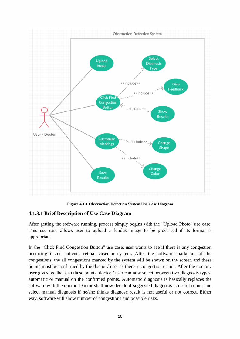
Figure 4.1.1 presents a use case diagram for the subject obstruction system. The system shows
the operations that end users can perform.
10
Figure 4.1.1 Obstruction Detection System Use Case Diagram
4.1.3.1 Brief Description of Use Case Diagram
After getting the software running, process simply begins with the "Upload Photo" use case.
This use case allows user to upload a fundus image to be processed if its format is
appropriate.
In the "Click Find Congestion Button" use case, user wants to see if there is any congestion
occurring inside patient's retinal vascular system. After the software marks all of the
congestions, the all congestions marked by the system will be shown on the screen and these
points must be confirmed by the doctor / user as there is congestion or not. After the doctor /
user gives feedback to these points, doctor / user can now select between two diagnosis types,
automatic or manual on the confirmed points. Automatic diagnosis is basically replaces the
software with the doctor. Doctor shall now decide if suggested diagnosis is useful or not and
select manual diagnosis if he/she thinks diagnose result is not useful or not correct. Either
way, software will show number of congestions and possible risks.
11
In the "Customize Markings" use case, user is allowed to determine the shape and color of the
marks in order to maximize visibility.
After all of the process has done, user is given ability to save processed image along with its
results as a package at wherever he/she wants. Package is simply a folder composed of an
image and a .txt file which keeps the results.
4.1.4 Use Case Descriptions
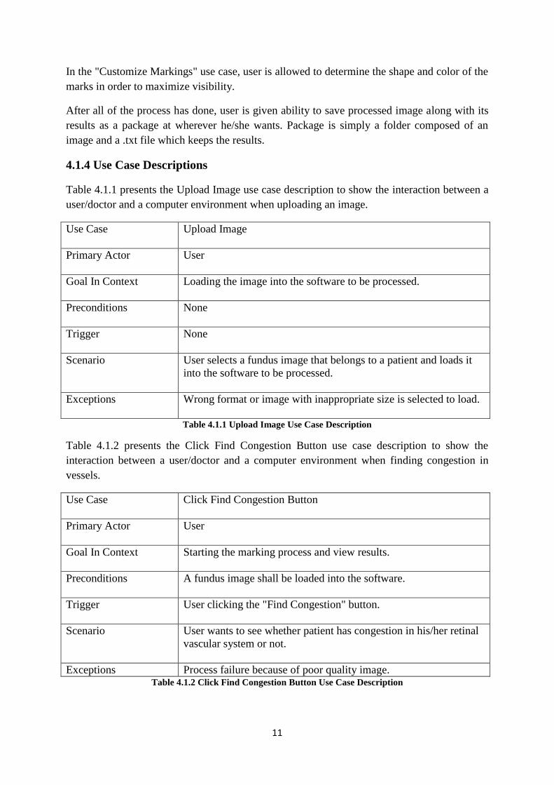
Table 4.1.1 presents the Upload Image use case description to show the interaction between a
user/doctor and a computer environment when uploading an image.
Use Case Upload Image
Primary Actor User
Goal In Context Loading the image into the software to be processed.
Preconditions None
Trigger None
Scenario User selects a fundus image that belongs to a patient and loads it
into the software to be processed.
Exceptions Wrong format or image with inappropriate size is selected to load.
Table 4.1.1 Upload Image Use Case Description
Table 4.1.2 presents the Click Find Congestion Button use case description to show the
interaction between a user/doctor and a computer environment when finding congestion in
vessels.
Use Case Click Find Congestion Button
Primary Actor User
Goal In Context Starting the marking process and view results.
Preconditions A fundus image shall be loaded into the software.
Trigger User clicking the "Find Congestion" button.
Scenario User wants to see whether patient has congestion in his/her retinal
vascular system or not.
Exceptions Process failure because of poor quality image. Table 4.1.2 Click Find Congestion Button Use Case Description
12
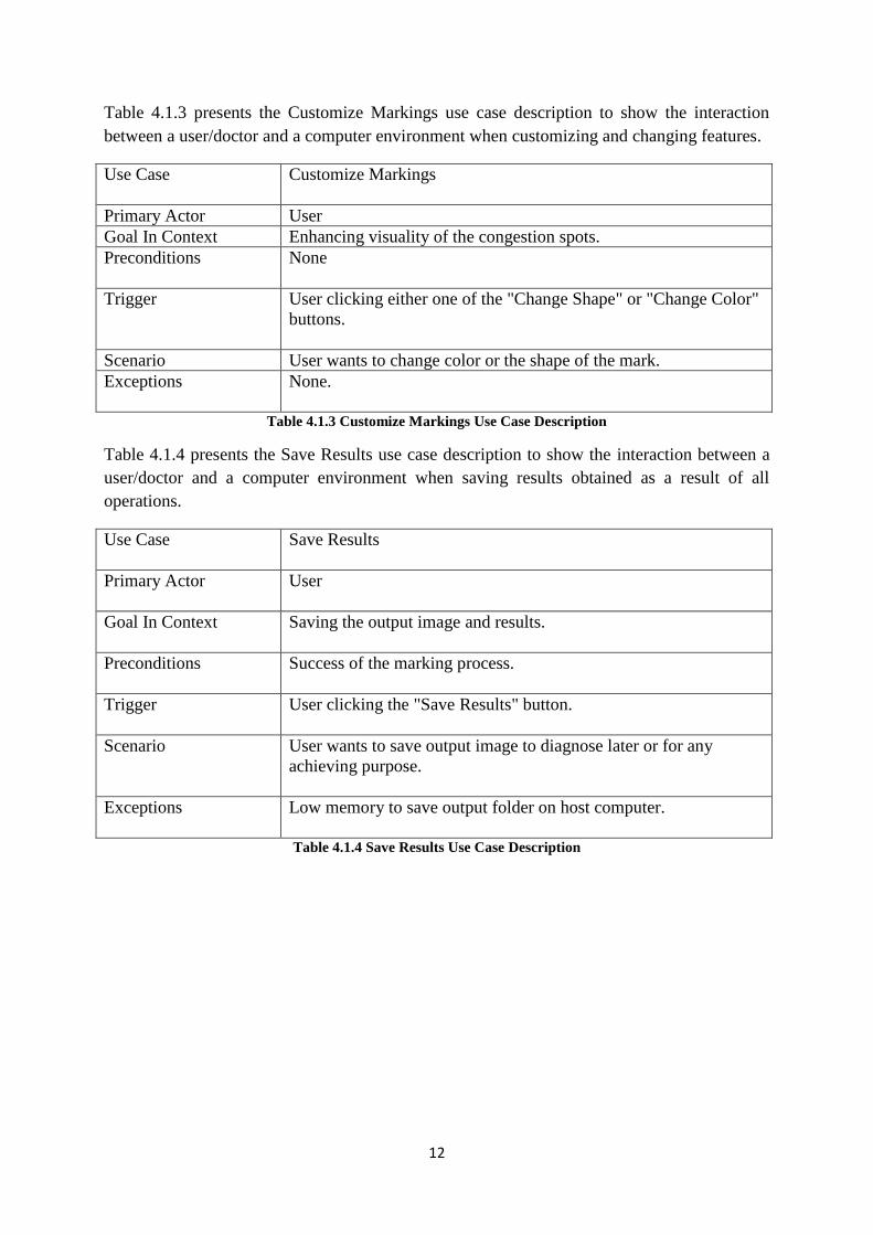
Table 4.1.3 presents the Customize Markings use case description to show the interaction
between a user/doctor and a computer environment when customizing and changing features.
Use Case Customize Markings
Primary Actor User
Goal In Context Enhancing visuality of the congestion spots.
Preconditions None
Trigger User clicking either one of the "Change Shape" or "Change Color"
buttons.
Scenario User wants to change color or the shape of the mark.
Exceptions None.
Table 4.1.3 Customize Markings Use Case Description
Table 4.1.4 presents the Save Results use case description to show the interaction between a
user/doctor and a computer environment when saving results obtained as a result of all
operations.
Use Case Save Results
Primary Actor User
Goal In Context Saving the output image and results.
Preconditions Success of the marking process.
Trigger User clicking the "Save Results" button.
Scenario User wants to save output image to diagnose later or for any
achieving purpose.
Exceptions Low memory to save output folder on host computer.
Table 4.1.4 Save Results Use Case Description
13
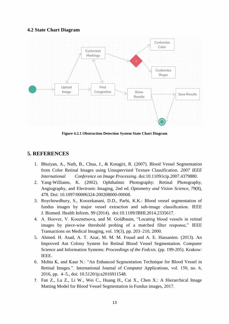
4.2 State Chart Diagram
Figure 4.2.1 Obstruction Detection System State Chart Diagram
5. REFERENCES
1. Bhuiyan, A., Nath, B., Chua, J., & Kotagiri, R. (2007). Blood Vessel Segmentation
from Color Retinal Images using Unsupervised Texture Classification. 2007 IEEE
International Conference on Image Processing. doi:10.1109/icip.2007.4379880.
2. Yang-Williams, K. (2002). Ophthalmic Photography: Retinal Photography,
Angiography, and Electronic Imaging, 2nd ed. Optometry and Vision Science, 79(8),
478. Doi: 10.1097/00006324-200208000-00008.
3. Roychowdhury, S., Koozekanani, D.D., Parhi, K.K.: Blood vessel segmentation of
fundus images by major vessel extraction and sub-image classification. IEEE
J. Biomed. Health Inform. 99 (2014). doi:10.1109/JBHI.2014.2335617.
4. A. Hoover, V. Kouznetsova, and M. Goldbaum, “Locating blood vessels in retinal
images by piece-wise threshold probing of a matched filter response,” IEEE
Transactions on Medical Imaging, vol. 19(3), pp. 203–210, 2000.
5. Ahmed. H. Asad, A. T. Azar, M. M. M. Fouad and A. E. Hassanien. (2013). An
Improved Ant Colony System for Retinal Blood Vessel Segmentation. Computer
Science and Information Systems: Proceedings of the Fedcsis. (pp. 199-205). Krakow:
IEEE.
6. Mehta K, and Kaur N.: “An Enhanced Segmentation Technique for Blood Vessel in
Retinal Images.”. International Journal of Computer Applications, vol. 150, no. 6,
2016, pp. 4–5., doi: 10.5120/ijca2016911548.
7. Fan Z., Lu Z., Li W., Wei C., Huang H., Cai X., Chen X.: A Hierarchical Image
Matting Model for Blood Vessel Segmentation in Fundus images, 2017.