smv devicenettm communications module communications ...download.lenze.com/td/com__esv__smv...
TRANSCRIPT

SMV DeviceNetTM Communications ModuleCommunications Interface Reference Guide
This documentation applies to the optional DeviceNet™ communications module for the SMVector inverter and should be used in conjunction with the SMVector Operating Instructions (Document SV01) that shipped with the drive. These documents should be read in their entirety as they contain important technical data and describe the installation and operation of the drive.
© 2007 Lenze AC Tech Corporation
No part of this documentation may be copied or made available to third parties without the explicit written approval of Lenze AC Tech Corporation.
All information given in this documentation has been carefully selected and tested for compliance with the hardware and software described. Nevertheless, discrepancies cannot be ruled out. Lenze AC Tech Corporation does not accept any responsibility nor liability for damages that may occur. Any necessary corrections will be implemented in subsequent editions.
SMVector®, and all related indicia are trademarks of Lenze AG in the United States and other countries.
CompoNet™, DeviceNet™, CIP™, CIP Safety™, CIP Sync™, CIP Motion™, DeviceNet Safety™ and EtherNet/IP Safety™ and all related indicia are trademarks of the ODVA (Open DeviceNet Vendors Association). EtherNet/IP™ is a trademark used under license by ODVA.
RSNetWorx™, RSNetWorx™ for DeviceNet, Allen Bradley® and all related indicia are either registered trademarks or trademarks of Rockwell Automation® Corporation.
About These Instructions

CMVDVN01B 2
Contents
1 Safety Information .......................................................................................................................................4
1.1 Warnings, Cautions and Notes .......................................................................................................4
1.1.1 General ............................................................................................................................4
1.1.2 Application .......................................................................................................................4
1.1.3 Installation .......................................................................................................................4
1.1.4 Electrical Connection .......................................................................................................4
1.1.5 Operation .........................................................................................................................5
1.2 Reference Documentation .............................................................................................................5
2 Introduction .................................................................................................................................................6
2.1 Fieldbus Overview .........................................................................................................................6
2.2 Module Specification .....................................................................................................................6
2.3 Module Identification Label ............................................................................................................7
3 Installation ..................................................................................................................................................8
3.1 Mechanical Installation ..................................................................................................................8
3.2 DeviceNet Terminal Block ..............................................................................................................9
3.3 Electrical Installation ......................................................................................................................9
3.3.1 Cable Types .....................................................................................................................9
3.3.2 Network Limitations .........................................................................................................9
3.3.3 Connections and Shielding ...............................................................................................10
3.3.4 Network Termination .......................................................................................................11
4 Commissioning DeviceNet Communication ..................................................................................................12
4.1 Overview .......................................................................................................................................12
4.2 Configuring the Network Master ....................................................................................................12
4.2.1 Master Support Files ........................................................................................................12
4.2.2 DeviceNet Master Setup Procedure ..................................................................................12
4.3 Configuring the SMV DeviceNet Module .........................................................................................13
4.3.1 Connecting ......................................................................................................................13
4.3.2 Setting the Network Protocol ............................................................................................13
4.3.3 Node Address (MAC-ID) ...................................................................................................13
4.3.4 Baud / Data Rate ..............................................................................................................14
4.3.5 Module Timeout Action ....................................................................................................14
4.3.6 Data Mapping ..................................................................................................................15
4.3.7 Re-initialising ...................................................................................................................15
4.3.8 Check Node Status ..........................................................................................................16
4.3.9 Non-Module Parameter Settings ......................................................................................16
4.3.10 Sample Setup and Wiring for DeviceNet Control ...............................................................16
4.3.11 Sample of Setup and Test Runs using Rsnetworx for DeviceNet .......................................17

3 CMVDVN01B
Contents
5 Cyclic Data Access ......................................................................................................................................18
5.1 What is Cyclic Data? ......................................................................................................................18
5.2 Mapping Cyclic Data ......................................................................................................................18
5.2.1 Data OUT .........................................................................................................................18
5.2.2 Data IN ............................................................................................................................18
5.3 Input/Output Assembly Configuration Mappings .............................................................................19
5.3.1 Output Assembly Details .................................................................................................19
5.3.2 Input Assembly Details ....................................................................................................22
6 Troubleshooting and Fault Elimination .........................................................................................................25
6.1 Faults ............................................................................................................................................25
6.2 Troubleshooting .............................................................................................................................25
7 Reference ...................................................................................................................................................26
7.1 P400 Parameter Menu ...................................................................................................................26
7.2 Class Implementation Details .........................................................................................................32
7.2.1 Identity Object - Class 0x01 .............................................................................................32
7.2.2 Message Router Object - Class 0x02................................................................................32
7.2.3 DeviceNet Object - Class 0x03 .........................................................................................33
7.2.4 Assembly Object - Class 0x04 ..........................................................................................34
7.2.5 DeviceNet Connection Object - Class 0x05 .......................................................................35
7.2.6 Parameter Object - Class 0x0F .........................................................................................39
7.2.7 Parameter Group Object - Class 0x10 ..............................................................................47
7.2.8 Motor Data Object - Class 0x28 .......................................................................................47
7.2.9 Control Supervisor Object - Class 0x29 ............................................................................48
7.2.10 AC/DC Drive Object - Class 0x2A......................................................................................51
7.2.11 Acknowledge Handler Object - Class 0x2B .......................................................................52

CMVDVN01B 4
Safety Information
1 SafetyInformation1.1 Warnings,CautionsandNotes1.1.1 General
Some parts of Lenze controllers (frequency inverters, servo inverters, DC controllers) can be live, moving and rotating. Some surfaces can be hot. Non-authorized removal of the required cover, inappropriate use, and incorrect installation or operation creates the risk of severe injury to personnel or damage to equipment.
All operations concerning transport, installation, and commissioning as well as maintenance must be carried out by qualified, skilled personnel (IEC 364 and CENELEC HD 384 or DIN VDE 0100 and IEC report 664 or DIN VDE0110 and national regulations for the prevention of accidents must be observed).
According to this basic safety information, qualified skilled personnel are persons who are familiar with the installation, assembly, commissioning, and operation of the product and who have the qualifications necessary for their occupation.
1.1.2 Application
Drive controllers are components designed for installation in electrical systems or machinery. They are not to be used as appliances. They are intended exclusively for professional and commercial purposes according to EN 61000-3-2. The documentation includes information on compliance with the EN 61000-3-2.
When installing the drive controllers in machines, commissioning (i.e. the starting of operation as directed) is prohibited until it is proven that the machine complies with the regulations of the EC Directive 2006/42/EC (Machinery Directive); EN 60204 must be observed.
Commissioning (i.e. starting drive as directed) is only allowed when there is compliance to the EMC Directive (2004/108/EC). The drive controllers meet the requirements of the Low Voltage Directive 2006/95/EC. The harmonised standards of the series EN 50178/DIN VDE 0160 apply to the controllers.
The availability of controllers is restricted according to EN 61800-3. These products can cause radiointerferenceinresidentialareas.Inthecaseofradiointerference,specialmeasuresmaybenecessaryfordrivecontrollers.
1.1.3 Installation
Ensure proper handling and avoid excessive mechanical stress. Do not bend any components and do not change any insulation distances during transport or handling. Do not touch any electronic components and contacts.
Controllers contain electrostatically sensitive components, which can easily be damaged by inappropriate handling. Do not damage or destroy any electrical components since this might endanger your health!
1.1.4 ElectricalConnection
When working on live drive controllers, applicable national regulations for the prevention of accidents (e.g. VBG 4) must be observed. The electrical installation must be carried out according to the appropriate regulations (e.g. cable cross-sections, fuses, PE connection). Additional information can be obtained from the regulatory documentation.
The regulatory documentation contains information about installation in compliance with EMC (shielding, grounding, filters and cables). These notes must also be observed for CE-marked controllers.
The manufacturer of the system or machine is responsible for compliance with the required limit values demanded by EMC legislation.

5 CMVDVN01B
Safety Information
1.1.5 Operation
Systems including controllers must be equipped with additional monitoring and protection devices according to the corresponding standards (e.g. technical equipment, regulations for prevention of accidents, etc.). The user is allowed to adapt the controller to his application as described in the regulatory documentation.
DANGER!• After the controller has been disconnected from the supply voltage, do not touch the live
components and power connection until the capacitors have discharged. Please observe the corresponding notes on the controller.
• Do not continuously cycle input power to the controller more than once every three minutes.• Please close all protective covers and doors during operation.
WARNING!Network control permits automatic starting and stopping of the inverter drive. The system design must incorporate adequate protection to prevent personnel from accessing moving equipment while power is applied to the drive system.
Table 1: Pictographs used in these instructions
Pictograph SignalWord Meaning Consequencesifignored
DANGER! Warning of Hazardous Electrical Voltage.
Reference to an imminent danger that may result in death or serious personal injury if the corresponding measures are not taken.
WARNING! Impending or possible danger for persons
Death or injury
STOP! Possible damage to equipment Damage to drive system or its surroundings
NOTE Useful tip: If observed, it will make using the drive easier
1.2 ReferenceDocumentation• SV01, SMV Operating Instructions: Technical Library: http://www.lenzeamericas.com
• AN0023, Getting Started with DeviceNet (PS & SMV Drives): Technical Library: http://www.lenzeamericas.com
• DeviceNet™ Information, ODVA (Open DeviceNet Vendor's Association): http://www.odva.org

CMVDVN01B 6
Introduction
2 IntroductionThe following information is provided to allow the SMV Series drive to operate on a DeviceNet network; it is not intended to explain how DeviceNet™ itself works. Therefore, a working knowledge of DeviceNet is assumed, as well as familiarity with the operation of the SMV Series drive.
2.1 FieldbusOverviewThe DeviceNet fieldbus is an internationally accepted communications protocol designed for commercial and industrial installations of factory automation and motion control applications. High data transfer rates combined with it’s efficient data formatting, permit the coordination and control of multi-node applications.
2.2 ModuleSpecification• Group 2 Server Device
• Supported Baudrates: 125 kbps, 250 kbps, 500 kbps
• Supported input/output data words: Polled, Bit Strobe, Changed of state, Cyclic
• Explicit communication for parameter access
NOTE:The SMV does not support the Explicit Unconnected Message Manager!
To simplify setup and operation, implemented classes and behavior conform to the AC DRIVE profile as specified in the ODVA DeviceNet standard.
To assist in recovery from Communication Faulted condition, Offline Connection Set messages are supported. The SMV supports the following Group 4 message types:
Group 4 Message ID 2C - Communication Faulted Response Message
Group 4 Message ID 2D - Communication Faulted Request Message
Using these messages, the user will be able to identify a faulted drive and when possible, re-establish communication without disconnecting the network or resetting the drive. After receiving “Identify Request Message” while in Communication Faulted state, the value in parameter P419 will flash “1000/1777”.
The SMV drive supports these object classes:
• Identity Object - Class 0x01
• Message Router Object - Class 0x02
• DeviceNet Object - Class 0x03
• Assembly Object - Class 0x04
• DeviceNet Connection Object - Class 0x05
• Parameter Object - Class 0x0F
• Parameter Group Object -Class 0x10
• Motor Data Object - Class 0x28
• Control Supervisor Object - Class 0x29
• AC/DC Drive Object - Class 0x2A
• Acknowledge Handler Object - Class 0x2B

7 CMVDVN01B
Introduction
2.3 ModuleIdentificationLabelFigure 1 illustrates the labels on the DeviceNet communications module. The SMV DeviceNet module is identifiable by:
• Two labels affixed to either side of the module.
• The color-coded identifier label in the center of the module
D0
Right-hand Label:Ratings & Certifications
LISTED
COMM I/O ONLYS/N: 123456789
ESVZAD0-000XX1A10
Fieldbus Identifier:D0 = DeviceNet
A: Fieldbus ProtocolB: Model NumberC: Lenze Order NumberD: Firmware RevisionE: Hardware Revision
SMV DeviceNetTYPE: ESVZAD0
ID-NO: 12345678
ESVZAD0-000XX1A10
ABCD
E
Left-hand Label:Module Data
Figure 1: SMV DeviceNet Module Label
CMVDVN01B 8
Installation
3 Installation3.1 MechanicalInstallation
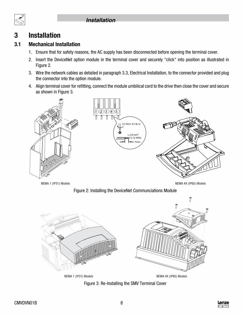
1. Ensure that for safety reasons, the AC supply has been disconnected before opening the terminal cover.
2. Insert the DeviceNet option module in the terminal cover and securely "click" into position as illustrated in Figure 2.
3. Wire the network cables as detailed in paragraph 3.3, Electrical Installation, to the connector provided and plug the connector into the option module.
4. Align terminal cover for refitting, connect the module umbilical cord to the drive then close the cover and secure as shown in Figure 3.
7mm
<_ 2.8 mm2 (12-22 AWG)
0.5 Nm/ 4.5 lb-in
1 2 3 4 5
NEMA 1 (IP31) Models NEMA 4X (IP65) Models
Figure 2: Installing the DeviceNet Communciations Module
NEMA 1 (IP31) Models NEMA 4X (IP65) Models
Figure 3: Re-Installing the SMV Terminal Cover

9 CMVDVN01B
Installation
3.2 DeviceNetTerminalBlockTable 2: DeviceNet Pin Assignments
Terminal Name WireColor Description TerminalBlock
1 V- Black 0V
1 2 3 45
2 CAN_L Blue CAN Bus Low (negative data line)
3 Shield Bare
4 CAN_H White CAN Bus High (positive data line)
5 V+ Red11 - 25 VDC power supply; current consumption
(100mA @ 11VDC max)
3.3 ElectricalInstallation3.3.1 CableTypes
Due to the high data rates used on DeviceNet networks, it is paramount that correctly specified cable is used. The use of low quality cable will result in excess signal attenuation and data loss. Several types of cable are available for DeviceNet networks: flat cable, thicknet, mid cable and thinnet. Installation is typically done with thicknet for trunk cable and thinnet for drop cable. Thicknet has a 3” minimum bend radius. Thinnet is more flexible, with a 2” minimum bend radius, and as such is easier to install. Thinnet can be used for the entire installation. The type of cable used, the lengths of the overall network and the drop cables all affect the maximum baud rate.
Cable specifications and approved manufacturers are available from the official DeviceNet website at: http://www.ovda.org.
3.3.2 NetworkLimitations
There are several factors that must be taken into consideration when designing a DeviceNet network. For full details refer to the official “DeviceNet™ Planning and Installation Manual” available on the http://www.ovda.org website. However, here is an abbreviated checklist:
• DeviceNet networks are limited to a maximum of 64 nodes. Devices default to node 63 so leave node 63 open to avoid duplicate node addresses when adding devices.
• Maximum total network length is governed by the data rate and cable type used. Refer to Table 3.
Table 3: Network Length, Drop Cable Length and Baud Rate
DataRate MAXIMUMNetworkLength SumofallDropCableLengths
Flat Cable Thicknet Mid Cable Thinnet
125 kbps 420m 500m 300m 100m 156m
250 kbps 200m 250m 250m 100m 78m
500 kbps 75m 100m 100m 100m 39m
• Cumulative drop line does not exceed the network specified limit.
• Network drops/spurs must not exceed 6 meters (19’ 8.2”).

CMVDVN01B 10
Installation
• Use fiber optic segments to:
• Extend networks beyond normal cable limitations
• Overcome different ground potential problems
• Overcome very high electromagnetic interference
• Ground at only one location, preferably in the center of the network.
3.3.3 ConnectionsandShielding
• ODVA specifies to ground the DeviceNet network at one location only.• The ground location should be done on the node that is closest to the physical center of the network to
maximize the performance and minimize the effect of outside noise.• The grounding connection method with regards to the network “V-” connections depends upon the cable type
used (refer to cable data sheet or OVDA “DeviceNet™ Planning and Installation Manual” for further details.
1 2 3 4 5 1 2 3 4 5
Connect tocubical panel/earthas close to the driveas possible
Figure 4: Network Daisy Chain Connection Figure 5: Ground Connection of Center Network Node
NOTEIf the bare screen is too long there is some risk that it may come into contact with the drive power terminals. Therefore it is strongly recommended that an insulating sleeve be fitted.
11 CMVDVN01B
Installation
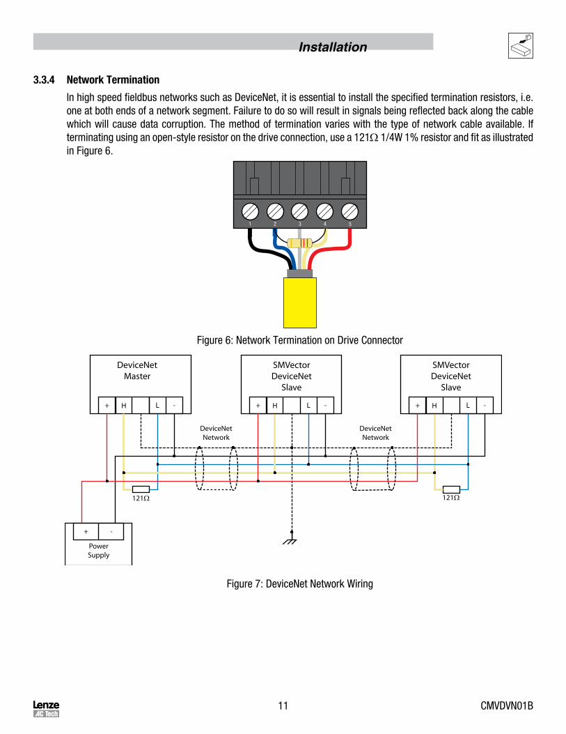
3.3.4 NetworkTermination
In high speed fieldbus networks such as DeviceNet, it is essential to install the specified termination resistors, i.e. one at both ends of a network segment. Failure to do so will result in signals being reflected back along the cable which will cause data corruption. The method of termination varies with the type of network cable available. If terminating using an open-style resistor on the drive connection, use a 121W 1/4W 1% resistor and fit as illustrated in Figure 6.
1 2 3 4 5
Figure 6: Network Termination on Drive Connector
DeviceNetMaster
SMVectorDeviceNet
Slave
SMVectorDeviceNet
Slave
+ H L
121Ω121Ω
DeviceNetNetwork
DeviceNetNetwork
- + H L - + H L -
+ -
PowerSupply
Figure 7: DeviceNet Network Wiring

CMVDVN01B 12
Commissioning
4 CommissioningDeviceNetCommunication4.1 Overview
It is assumed that the user has familiarised themselves with how to navigate through the drive parameters using the keypad. Refer to the drive user manual for details.
The details that follow provide a step-by-step guide to quickly and easily set-up an SMV drive to communicate on a DeviceNet fieldbus network, in a basic format. There are many more features and settings available for the DeviceNet option module, for details on these refer to the fuller description in the sections that follow.
4.2 ConfiguringtheNetworkMaster4.2.1 MasterSupportFiles
The EDS (Electronic Data Sheet) file is basically a lookup table. It tells the DeviceNet master (scanner) what the slave is and how its memory is mapped. The EDS file needs to be read into the DeviceNet master. The utility used for this purpose is RSNetworx for DeviceNet from Rockwell Automation.
To simplify setup, the EDS file supporting the SMV Series drive is available from Lenze-AC Tech. To obtain a copy of the appropriate EDS file, please contact Lenze-AC Tech or visit www.lenzeamericas.com. The EDS file is also included on the CD that shipped with the drive.
Use RSNetworx for DeviceNet to configure the data exchange between the AC Tech drive and the DeviceNet master. First use the “EDS Hardware Installation tool” to register the EDS file of the drive. Once the EDS file is registered, change to ONLINE mode and browse the network. Locate an icon for the AC Tech drive at its configured network address. Add the drive to the scan list for the DeviceNet master and define the I/O connection. By default, “Polled” is used for most applications. Double click on the icon for the drive to allow the drive parameters to be read and edited.
4.2.2 DeviceNetMasterSetupProcedure
Details for configuring a specific network master are NOT provided herein. The method for configuring master devices differs greatly between manufacturers. Provided herein is a very basic, generic guide to setting up a network master.
1. Launch the Master configuration software.2. Install/Import the required ESD support file(s) using the wizard tool if provided.3. Setup master DeviceNet port with required cirteria such as node address and baudrate etc.4. Add or “drag and drop” the required slave devices from the ESD library to the DeviceNet network which is
typically depicted on screen.5. Configure the slave node address, ensuring that each node has a unique and individual address.6. Configure each slave's I/O data size. (This is typically done by dragging and dropping the required amount of
modules from the ESD file library or picking the modules from a list).7. Save the configuration and download to the Master.
13 CMVDVN01B
Commissioning
4.3 ConfiguringtheSMVDeviceNetModule4.3.1 Connecting
With the drive power disconnected install the DeviceNet module and connect the network cable as instructed in the preceeding section 3.1. Ensure the drive Run/Enable terminal is disabled then apply the correct voltage to the drive (refer to the drive's user manual for voltage supply details).
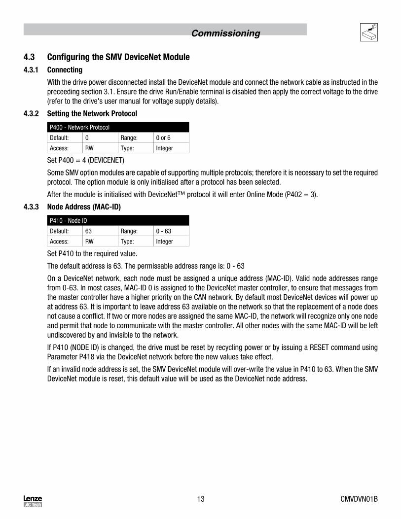
4.3.2 SettingtheNetworkProtocol
P400 - Network Protocol
Default: 0 Range: 0 or 6
Access: RW Type: Integer
Set P400 = 4 (DEVICENET)
Some SMV option modules are capable of supporting multiple protocols; therefore it is necessary to set the required protocol. The option module is only initialised after a protocol has been selected.
After the module is initialised with DeviceNet™ protocol it will enter Online Mode (P402 = 3).
4.3.3 NodeAddress(MAC-ID)
P410 - Node ID
Default: 63 Range: 0 - 63
Access: RW Type: Integer
Set P410 to the required value.
The default address is 63. The permissable address range is: 0 - 63
On a DeviceNet network, each node must be assigned a unique address (MAC-ID). Valid node addresses range from 0-63. In most cases, MAC-ID 0 is assigned to the DeviceNet master controller, to ensure that messages from the master controller have a higher priority on the CAN network. By default most DeviceNet devices will power up at address 63. It is important to leave address 63 available on the network so that the replacement of a node does not cause a conflict. If two or more nodes are assigned the same MAC-ID, the network will recognize only one node and permit that node to communicate with the master controller. All other nodes with the same MAC-ID will be left undiscovered by and invisible to the network.
If P410 (NODE ID) is changed, the drive must be reset by recycling power or by issuing a RESET command using Parameter P418 via the DeviceNet network before the new values take effect.
If an invalid node address is set, the SMV DeviceNet module will over-write the value in P410 to 63. When the SMV DeviceNet module is reset, this default value will be used as the DeviceNet node address.
CMVDVN01B 14
Commissioning
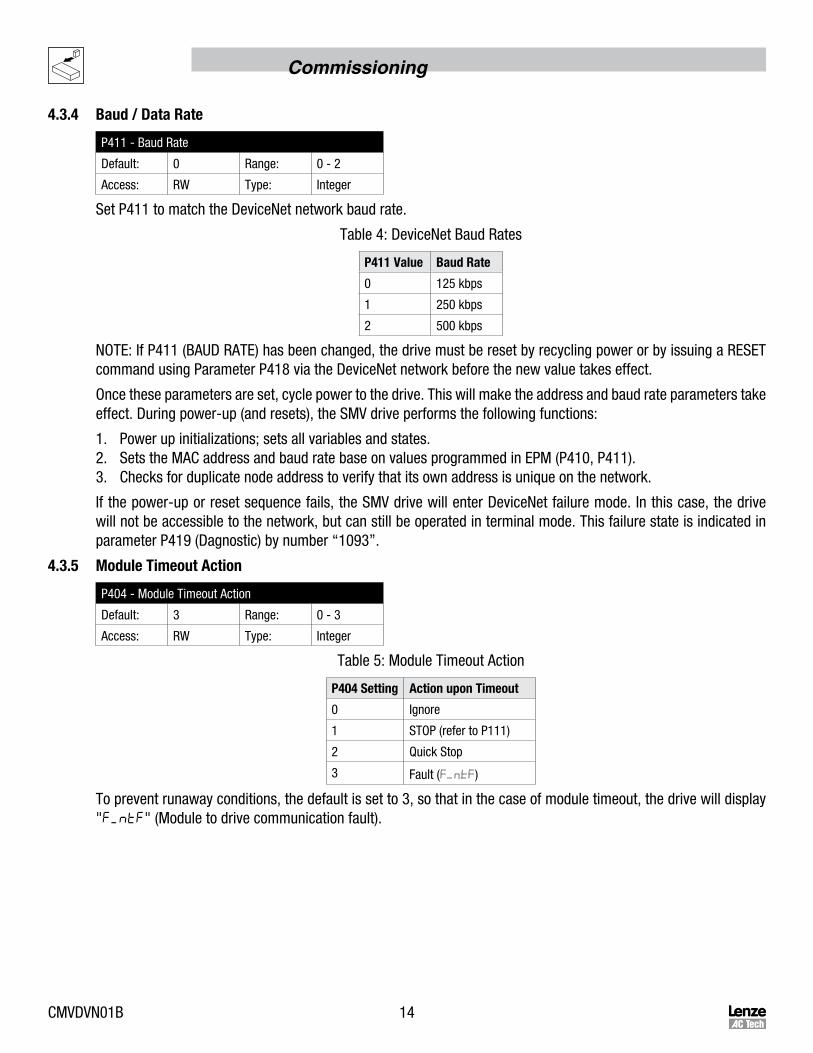
4.3.4 Baud/DataRate
P411 - Baud Rate
Default: 0 Range: 0 - 2
Access: RW Type: Integer
Set P411 to match the DeviceNet network baud rate.
Table 4: DeviceNet Baud Rates
P411Value BaudRate
0 125 kbps
1 250 kbps
2 500 kbps
NOTE: If P411 (BAUD RATE) has been changed, the drive must be reset by recycling power or by issuing a RESET command using Parameter P418 via the DeviceNet network before the new value takes effect.
Once these parameters are set, cycle power to the drive. This will make the address and baud rate parameters take effect. During power-up (and resets), the SMV drive performs the following functions:
1. Power up initializations; sets all variables and states.2. Sets the MAC address and baud rate base on values programmed in EPM (P410, P411).3. Checks for duplicate node address to verify that its own address is unique on the network.
If the power-up or reset sequence fails, the SMV drive will enter DeviceNet failure mode. In this case, the drive will not be accessible to the network, but can still be operated in terminal mode. This failure state is indicated in parameter P419 (Dagnostic) by number “1093”.
4.3.5 ModuleTimeoutAction
P404 - Module Timeout Action
Default: 3 Range: 0 - 3
Access: RW Type: Integer
Table 5: Module Timeout Action
P404Setting ActionuponTimeout
0 Ignore
1 STOP (refer to P111)
2 Quick Stop
3 Fault ( )
To prevent runaway conditions, the default is set to 3, so that in the case of module timeout, the drive will display "F_ntF" (Module to drive communication fault).
15 CMVDVN01B
Commissioning
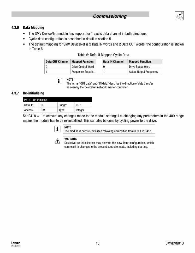
4.3.6 DataMapping
• The SMV DeviceNet module has support for 1 cyclic data channel in both directions.• Cyclic data configuration is described in detail in section 5.• The default mapping for SMV DeviceNet is 2 Data IN words and 2 Data OUT words, the configuration is shown
in Table 6.
Table 6: Default Mapped Cyclic Data
DataOUTChannel MappedFunction DataINChannel MappedFunction
0 Drive Control Word 0 Drive Status Word
1 Frequency Setpoint 1 Actual Output Frequency
NOTEThe terms “OUT data” and “IN data” describe the direction of data transfer as seen by the DeviceNet network master controller.
4.3.7 Re-initialising
P418 - Re-initialise
Default: 0 Range: 0 - 1
Access: RW Type: Integer
Set P418 = 1 to activate any changes made to the module settings i.e. changing any parameters in the 400 range means the module has to be re-initialised. This can also be done by cycling power to the drive.
NOTEThe module is only re-initialised following a transition from 0 to 1 in P418
WARNINGDeviceNet re-initialisation may activate the new Dout configuration, which can result in changes to the present controller state, including starting.

CMVDVN01B 16
Commissioning
4.3.8 CheckNodeStatus
P419 - DeviceNet Status
Default: N/A Range: 0 - 4
Access: RO Type: Integer
P419 is a 4-digit integer. Digit 1 represents the Power Status, Digit 2 the Control Status, Digit 3 the Network Status and Digit 4 the I/O Status. Refer to Table 7 for the DeviceNet Status description.
Table 7: DeviceNet Module Status
P419Digit DigitRepresnts Selection
1 Power Status 1 = External power supply ON
2 Control Status 0 = Local Control and Reference1 = Network Control, Local Reference2 = Local Control, Network Reference3 = Network Control, Network Reference
3 Network Status 0 = Network not connected1 = Network not connected2 = Network connection time out3 = Communication faulted5 = Network connected8 = Duplicate MAC-ID failure9 = Network critical link failure
4 I/O Status 0 = I/O connection off1 = I/O connection idle state3 = I/O faulted5 = I/O active9 = I/O critical error
4.3.9 Non-ModuleParameterSettings
In addition to configuring the DeviceNet module there are several drive based parameters that may need to be set
• P100 - Start Control Source; network control is possible in any mode except mode 2 (“Remote Keypad Only”).
• P112 - Rotation; Used to enable either uni or bi direction rotation of the motor.
• P121, 122 or 123 = 9. One of the digital inputs must be assigned to mode 9 - “Network Control” and have the corresponding input closed to enable write access to the drive parameters.
4.3.10 SampleSetupandWiringforDeviceNetControl
This example uses Explicit or I/O Polled messaging for Run Forward/Reverse and speed control. NOTE: If P100>0, then Terminal 1 must be closed to Terminal 4 in order to start the drive through the DeviceNet interface. Parameters can be setup using the drive keypad, EPM Programmer, or DeviceNet configuration tool (for example RSNetWorxTM) that uses the EDS file provided by Lenze - AC Tech.
As a minimum, the following parameters should be set:
P121, P122, P123 - One of these parameters must be set to 09 (Network Enable)P112 ROTATION DIRECTION - Set this parameter to FORWARD & REVERSE (01) if operation in both directions is
required.P305 MOTOR NOMINAL SPEED AT RATED FREQUENCY (RPM)P304 MOTOR RATED FREQUENCY (Hz)

17 CMVDVN01B
Commissioning
P400 DEVICENET NODE ADDRESS (0 - 63)P401 DEVICENET BAUD RATE (125, 250, 500 kbps)P430 DEVICENET OUTPUT ASSEMBLY SELECTION - Set this parameter to select output assembly for Polled
connection. The following selections are available:0 = 20 Basic Speed Control1 = 21 Extended Speed Control RPM2 = 100 Extended Speed Control Hz + Digital and Analog Output 13 = 102 PID Setpoint + Digital + Analog Output 14 = 104 Torque Setpoint + Digital + Analog Output 1
The most versatile assemblies are #21 (selection 1) and #100 (selection 2). They allow RUN FORWARD and RUN REVERSE control as well as speed control. Refer to Section 5.2 for more assembly details.
P440 DEVICENET INPUT ASSEMBLY SELECTION - Set this parameter for Polled, COS or Cyclic I/O connection. Refer to Section 5.2 for more assembly details.
NOTE: If Parameter P400 (NETWORK ADDRESS) or P401 (BAUD RATE) have been changed, the drive must be reset by recycling power or by issuing a RESET command using Parameter P418 via the DeviceNet network before the new values take effect.
4.3.11 SampleofSetupandTestRunsusingRsnetworxforDeviceNet
1. Make all necessary DeviceNet network connections.
2. Using "EDS Hardware Installation Tool" register the EDS file for SMV family of drives.
3. Switch mode to ONLINE. After browsing through all available addresses on the network, "AC Tech SMV Drive" should appear at the programmed address.
4. To access the drive parameters double click on the drive icon.
5. After uploading parameters from the SMV drive, they can be edited and downloaded back to the drive. SMV drive parameters accessed through the drive keypad correspond to the same Network ID, to simplify programming they have a drive parameter number in front of their name.
For example:
Parameter ID P160 corresponds to drive parameter "P160 Carrier Select"
Parameter ID P110 corresponds to drive parameter "P110 Start Method"
DeviceNet parameter IDs #1 to #99 are only accessible through the network connection. Refer to the Parameter Class section for parameter descriptions.
To assist in Network Controlled test runs, the EDS file consists of parameters that permit triggering RUN commands by changing the bits setable in ID#65 (Network Control Word).
NOTE: RUN and STOP commands must be triggered according to the table in Section 5.3.6
ID#61 - Network Reference Frequency: Controls the drive speed reference parameter if bit 6 (Network Reference) is set to Network Control.
WARNING!Make sure it is safe to operate the driven equipment prior to starting the SMV Series drive from the network. Damage to equipment and/or injury to personnel can result!
CMVDVN01B 18
Cyclic Data Access
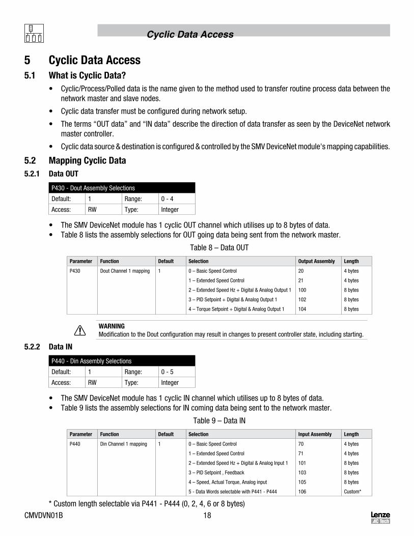
5 CyclicDataAccess5.1 WhatisCyclicData?
• Cyclic/Process/Polled data is the name given to the method used to transfer routine process data between the network master and slave nodes.
• Cyclic data transfer must be configured during network setup.
• The terms “OUT data” and “IN data” describe the direction of data transfer as seen by the DeviceNet network master controller.
• Cyclic data source & destination is configured & controlled by the SMV DeviceNet module's mapping capabilities.
5.2 MappingCyclicData5.2.1 DataOUT
P430 - Dout Assembly Selections
Default: 1 Range: 0 - 4
Access: RW Type: Integer
• The SMV DeviceNet module has 1 cyclic OUT channel which utilises up to 8 bytes of data.• Table 8 lists the assembly selections for OUT going data being sent from the network master.
Table 8 – Data OUT
Parameter Function Default Selection OutputAssembly Length
P430 Dout Channel 1 mapping 1 0 – Basic Speed Control
1 – Extended Speed Control
2 – Extended Speed Hz + Digital & Analog Output 1
3 – PID Setpoint + Digital & Analog Output 1
4 – Torque Setpoint + Digital & Analog Output 1
20
21
100
102
104
4 bytes
4 bytes
8 bytes
8 bytes
8 bytes
WARNINGModification to the Dout configuration may result in changes to present controller state, including starting.
5.2.2 DataIN
P440 - Din Assembly Selections
Default: 1 Range: 0 - 5
Access: RW Type: Integer
• The SMV DeviceNet module has 1 cyclic IN channel which utilises up to 8 bytes of data.• Table 9 lists the assembly selections for IN coming data being sent to the network master.
Table 9 – Data IN
Parameter Function Default Selection InputAssembly Length
P440 Din Channel 1 mapping 1 0 – Basic Speed Control
1 – Extended Speed Control
2 – Extended Speed Hz + Digital & Analog Input 1
3 – PID Setpoint , Feedback
4 – Speed, Actual Torque, Analog input
5 - Data Words selectable with P441 - P444
70
71
101
103
105
106
4 bytes
4 bytes
8 bytes
8 bytes
8 bytes
Custom*
* Custom length selectable via P441 - P444 (0, 2, 4, 6 or 8 bytes)

19 CMVDVN01B
Cyclic Data Access
5.3 Input/OutputAssemblyConfigurationMappings5.3.1 OutputAssemblyDetails
P430 = 0: Output Assembly 20 Basic Speed Control
P430 = 1: Output Assembly 21 Extended Speed Control
WOR
D0
Bit P430=0
WOR
D0
Bit P430=1
00 = NOT Run Forward1 = Run Forward
00 = NOT Run Forward1 = Run Forward
1 Reserved 10 = NOT Run Reverse1 = Run Reverse
2 Fault reset on transition from 0 to 1 2 Fault reset on transition from 0 to 1
3 Reserved 3 Reserved
4 Reserved 4 Reserved
5 Reserved 50 = Local Control1 = Network Control
6 Reserved 60 = Local Speed Ref1 = Network Speed Ref
7 Reserved 7 Reserved
8 Reserved 8 Reserved
9 Reserved 9 Reserved
10 Reserved 10 Reserved
11 Reserved 11 Reserved
12 Reserved 12 Reserved
13 Reserved 13 Reserved
14 Reserved 14 Reserved
15 Reserved 15 Reserved
WOR
D1
Speed in RPMs (max 32767)• RPM calculation based on P304 and P305• Example 1: P304 = 60Hz; P305 = 1750 RPM request setpoint forward (CW) at 25.0 HZ = 25.0 x 1750/60 = 729 = 0x02D9 W
ORD1
Speed in RPMs (max 32767)• RPM calculation based on P304 and P305• Example 1: P304 = 60Hz; P305 = 1750 RPM request setpoint forward (CW) at 25.0 HZ = 25.0 x 1750/60 = 729 = 0x02D9
Attention:To use this Output Assembly 20, Network Control and Network Reference must be set using explicit communication by writing into the control word at NetID65. The bit configuration of this word matches the WORD0 of Output Assembly 100.

CMVDVN01B 20
Cyclic Data Access
P430 = 2: Output Assembly 100 Speed in Hz + Digital and Analog Output
P430 = 3: Output Assembly 102 PID Setpoint + Digital and Analog Output
WOR
D0
Bit P430=2
WOR
D0
Bit P430=3
00 = NOT Run Forward1 = Run Forward
00 = NOT Run Forward1 = Run Forward
10 = NOT Run Reverse1 = Run Reverse
10 = NOT Run Reverse1 = Run Reverse
2 Fault reset on transition from 0 to 1 2 Fault reset on transition from 0 to 1
3 Reserved 3 Reserved
4 Reserved 4 Reserved
50 = Local Control1 = Network Control
50 = Local Control1 = Network Control
60 = Local Speed Ref1 = Network Speed Ref
60 = Local Speed Ref1 = Network Speed Ref
7 Reserved 7 Reserved
8 Network Speed Reference (valid if bit 6 is set)0 = Network 6 = Preset #31 = Keypad 7 = Preset #4 (1)
2 = 0 - 10VDC 8 = Preset #5 (1)
3 = 4 - 20 mA 9 = Preset #6 (1)
4 = Preset #1 10 = Preset #7 (1)
5 = Preset #2 11 = MOP
8 Network Speed Reference (valid if bit 6 is set)0 = Network 6 = Preset #31 = Keypad 7 = Preset #4 (1)
2 = 0 - 10VDC 8 = Preset #5 (1)
3 = 4 - 20 mA 9 = Preset #6 (1)
4 = Preset #1 10 = Preset #7 (1)
5 = Preset #2 11 = MOP
9 9
10 10
11 11
120 = No Action1 = Inhibit (Coast to Stop)
120 = No Action1 = Inhibit (Coast to Stop)
130 = No Action1 = Activate (Quick Stop)
130 = No Action1 = Activate (Quick Stop)
14
0 = No Action1 = Force Manual Mode(active only in Network Control, PID mode will force open loop)
14
0 = No Action1 = Force Manual Mode(active only in Network Control, PID mode will force open loop)
150 = DC brake active1 = DC brake not active
150 = DC brake active1 = DC brake not active
WOR
D1
Unsigned speed 0.1 Hz resolutionReceived value = 0x01F0 = 49.6Hz
WOR
D1
Network PID setpointSigned value -999 to 31000
WOR
D2
Digital Output + Relay - Active when parameterP140, P142 = 25 Network ControlBit 9 - Open CollectorBit 10 - RelayOthers - Reserved for future use W
ORD2
Digital Output + Relay - Active when parameterP140, P142 = 25 Network ControlBit 9 - Open CollectorBit 10 - RelayOthers - Reserved for future use
WOR
D3
Analog Output [0.1 VDC] - Active when parameterP150 = 9 Network ControlReceived value = 0x024B = 5.87 [VDC]
WOR
D3
Analog Output [0.1 VDC] - Active when parameterP150 = 9 Network ControlReceived value = 0x024B = 5.87 [VDC]
(1) Presets #4, #5, #6 and #7 are ignored when the drive is operating in either PID mode or Torque mode.

21 CMVDVN01B
Cyclic Data Access
P430 = 4: Output Assembly 104 Torque Setpoint + Digital and Analog Output
WOR
D0
Bit P430=4
00 = NOT Run Forward1 = Run Forward
10 = NOT Run Reverse1 = Run Reverse
2 Fault reset on transition from 0 to 1
3 Reserved
4 Reserved
50 = Local Control1 = Network Control
60 = Local Speed Ref1 = Network Speed Ref
7 Reserved
8 Network Speed Reference (valid if bit 6 is set)0 = Network 6 = Preset #31 = Keypad 7 = Preset #4 (1)
2 = 0 - 10VDC 8 = Preset #5 (1)
3 = 4 - 20 mA 9 = Preset #6 (1)
4 = Preset #1 10 = Preset #7 (1)
5 = Preset #2 11 = MOP
9
10
11
120 = No Action1 = Inhibit (Coast to Stop)
130 = No Action1 = Activate Quick Stop)
14
0 = No Action1 = Force Manual Mode(active only in Network Control, PID mode will force open loop
150 = DC brake active1 = DC brake not active
WOR
D1
Unsigned torque setpoint0 - 400% limited by parameter P330 Torque Limit
WOR
D2
Digital Output + Relay - Active when parameterP140, P142 = 25 Network ControlBit 9 - Open CollectorBit 10 - RelayOthers - Reserved for future use
WOR
D3
Analog Output [0.1 VDC] - Active when parameterP150 = 9 Network ControlReceived value = 0x024B = 5.87 [VDC]
(1) Presets #4, #5, #6 and #7 are ignored when the drive is operating in either PID mode or Torque mode.

CMVDVN01B 22
Cyclic Data Access
5.3.2 InputAssemblyDetails
P440 = 0: Input Assembly 70 Basic Speed Control
P440 = 1: Input Assembly 71 Extended Speed Control
WOR
D0
Bit P440=0
WOR
D0
Bit P440=1
0 1 = Faulted 0 1 = Faulted
1 Reserved 1 Reserved
2 1 = Running Forward 2 1 = Running Forward
3 Reserved 3 1 = Running Reverse
4 Reserved 4 1 = Ready
5 Reserved 50 = Local Control1 = Network Control
6 Reserved 60 = Local Speed Ref1 = Network Speed Ref
7 Reserved 7 1 = At Reference
8 Reserved 8 Reserved
9 Reserved 9 Reserved
10 Reserved 10 Reserved
11 Reserved 11 Reserved
12 Reserved 12 Reserved
13 Reserved 13 Reserved
14 Reserved 14 Reserved
15 Reserved 15 Reserved
WOR
D1
Speed in RPMs (max 32767)• RPM calculation based on P304 and P305• Example 1: P304 = 60Hz; P305 = 1750 RPM request setpoint forward (CW) at 25.0 HZ = 25.0 x 1750/60 = 729 = 0x02D9 W
ORD1
Speed in RPMs (max 32767)• RPM calculation based on P304 and P305• Example 1: P304 = 60Hz; P305 = 1750 RPM request setpoint forward (CW) at 40.0 HZ = 40.0 x 1750/60 = 1166 = 0x048E

23 CMVDVN01B
Cyclic Data Access
P440 = 2: Input Assembly 101 Speed in Hz + Digital and Analog InputP440 = 3: Input Assembly 103 Speed in Hz + Actual PID Setpoint and Feedback
WOR
D0
Bit P440=2
WOR
D0
Bit P440=3
0 1 = Faulted 0 1 = Faulted
1 Reserved 1 Reserved
2 1 = Running Forward 2 1 = Running Forward
3 1 = Running Reverse 3 1 = Running Reverse
4 1 = Ready 4 1 = Ready
50 = Local Control1 = Network Control
50 = Local Control1 = Network Control
60 = Local Speed Ref1 = Network Speed Ref
60 = Local Speed Ref1 = Network Speed Ref
7 1 = At Reference 7 1 = At Reference
8 Actual Setpoint Source0 = Keypad 6 = Preset #41 = 0 - 10VDC 7 = Preset #52 = 4 - 20 mA 8 = Preset #6 3 = Preset #1 9 = Preset #74 = Preset #2 10 = MOP5 = Preset #3 11 = Network
8 Actual Setpoint Source0 = Keypad 6 = Preset #41 = 0 - 10VDC 7 = Preset #52 = 4 - 20 mA 8 = Preset #6 3 = Preset #1 9 = Preset #74 = Preset #2 10 = MOP5 = Preset #3 11 = Network
9 9
10 10
11 11
12 1 = PID Active (closed loop) 12 1 = PID Active (closed loop)
13 1 = Torque Mode Active 13 1 = Torque Mode Active
14 1 = Current Limit 14 1 = Current Limit
15 1 = DC Braking 15 1 = DC Braking
WOR
D1 Unsigned actual frequency 0.1 Hz resolution
WOR
D1 Unsigned actual frequency 0.1 Hz resolution
WOR
D2 Digital Input/Output State(See Note 1 for details)
WOR
D2 Actual PID SetpointSigned value -999 to 31000
WOR
D3 Analog Input 0 - 10 V TB [0.1VDC]Received value = 0x3A = 5.8 [VDC]
WOR
D3 Actual PID FeedbackSigned value -999 to 31000
Note 1: Digital I/O State
WOR
D -
Digi
tal I
nput
/Out
put S
tate Bit 0 Bit 8 TBC13C
Bit 1 Bit 9 TB14 OutState
Bit 2 Output Fault Bit 10 Relay State
Bit 3 Fast Current Limit State Bit 11 Charge Relay
Bit 4 TB1 ON Bit 12 Assertion Level
Bit 5 Bit 13
Bit 6 TB13A Bit 14
Bit 7 TB13B Bit 15

CMVDVN01B 24
Cyclic Data Access
P440 = 4: Input Assembly 105 Speed in Hz + Actual Torque and Analog InputP440 = 5: Input Assembly 106 Custom Selectable
WOR
D0
Bit P440=4
WOR
D0
Bit P440=5
0 1 = Faulted
Data from Parameter/ID specified in Parameter P441For Example:Setting P441 to 508 will place the value of parameter P508 Motor Current into the Word0 of Input Assembly 106
1 Reserved
2 1 = Running Forward
3 1 = Running Reverse
4 1 = Ready
50 = Local Control1 = Network Control
60 = Local Speed Ref1 = Network Speed Ref
7 1 = At Reference
8 Actual Setpoint Source0 = Keypad 6 = Preset #41 = 0 - 10VDC 7 = Preset #52 = 4 - 20 mA 8 = Preset #6 3 = Preset #1 9 = Preset #74 = Preset #2 10 = MOP5 = Preset #3 11 = Network
9
10
11
12 1 = PID Active (closed loop)
13 1 = Torque Mode Active
14 1 = Current Limit
15 1 = DC Braking
WOR
D1
Unsigned actual frequency 0.1 Hz resolution
WOR
D1
Data from Parameter/ID specified in Parameter P442For Example:Setting P442 to 527 will place the value of parameter P527 Actual Frequency into the Word1 of Input Assembly 106
WOR
D2
Actual Torque [%]
WOR
D2
Data from Parameter/ID specified in Parameter P443For Example:Setting P443 to 520 will place the value of parameter P527 0 - 10VDC Analog Input into the Word2 of Input Assembly 106
WOR
D3
Analog Input 0 - 10 V TB [0.1VDC]Received value = 0x3A = 5.8 [VDC]
WOR
D3
Data from Parameter/ID specified in Parameter P444For Example:Setting P444 to 506 will place the value of parameter P506 Motor Voltage into the Word3 of Input Assembly 106
Note: Value of Zero in Parameter P441 to P444 defines the end of Assembly 106.
25 CMVDVN01B
Troubleshooting & Fault Elimination
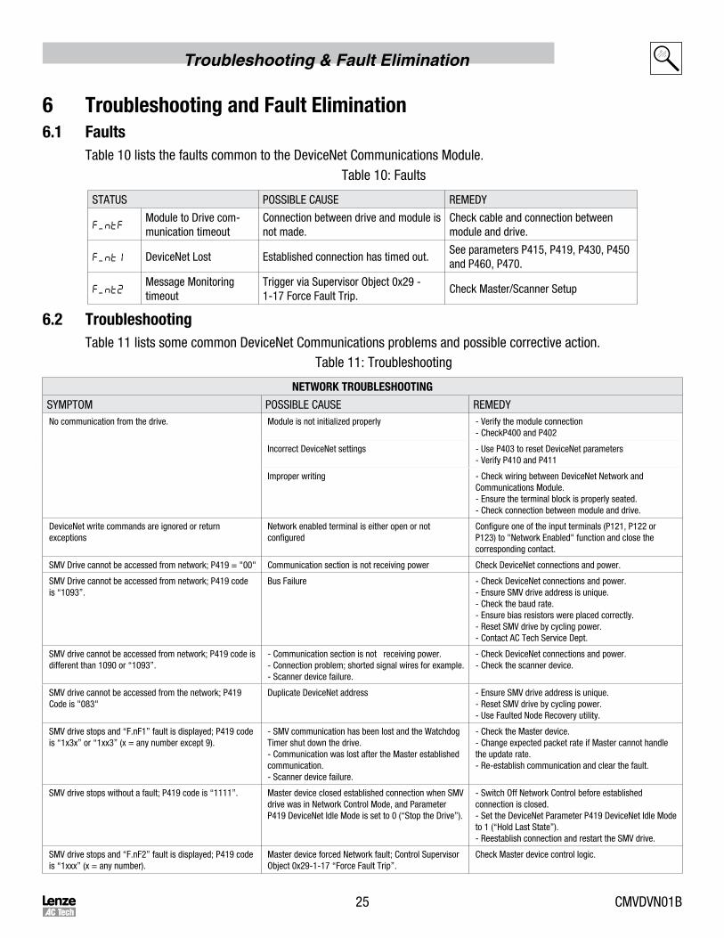
6 TroubleshootingandFaultElimination6.1 Faults
Table 10 lists the faults common to the DeviceNet Communications Module.Table 10: Faults
STATUS POSSIBLE CAUSE REMEDY
F.ntFModule to Drive com-munication timeout
Connection between drive and module is not made.
Check cable and connection between module and drive.
F.nt1 DeviceNet Lost Established connection has timed out.See parameters P415, P419, P430, P450 and P460, P470.
F.nt2Message Monitoring timeout
Trigger via Supervisor Object 0x29 - 1-17 Force Fault Trip.
Check Master/Scanner Setup
6.2 TroubleshootingTable 11 lists some common DeviceNet Communications problems and possible corrective action.
Table 11: Troubleshooting
NETWORKTROUBLESHOOTING
SYMPTOM POSSIBLE CAUSE REMEDYNo communication from the drive. Module is not initialized properly - Verify the module connection
- CheckP400 and P402
Incorrect DeviceNet settings - Use P403 to reset DeviceNet parameters- Verify P410 and P411
Improper writing - Check wiring between DeviceNet Network and Communications Module.- Ensure the terminal block is properly seated.- Check connection between module and drive.
DeviceNet write commands are ignored or return exceptions
Network enabled terminal is either open or not configured
Configure one of the input terminals (P121, P122 or P123) to "Network Enabled" function and close the corresponding contact.
SMV Drive cannot be accessed from network; P419 = "00" Communication section is not receiving power Check DeviceNet connections and power.
SMV Drive cannot be accessed from network; P419 code is “1093”.
Bus Failure - Check DeviceNet connections and power.- Ensure SMV drive address is unique.- Check the baud rate.- Ensure bias resistors were placed correctly.- Reset SMV drive by cycling power.- Contact AC Tech Service Dept.
SMV drive cannot be accessed from network; P419 code is different than 1090 or “1093”.
- Communication section is not receiving power.- Connection problem; shorted signal wires for example.- Scanner device failure.
- Check DeviceNet connections and power.- Check the scanner device.
SMV drive cannot be accessed from the network; P419 Code is "083"
Duplicate DeviceNet address - Ensure SMV drive address is unique.- Reset SMV drive by cycling power.- Use Faulted Node Recovery utility.
SMV drive stops and “F.nF1” fault is displayed; P419 code is “1x3x” or “1xx3” (x = any number except 9).
- SMV communication has been lost and the Watchdog Timer shut down the drive.- Communication was lost after the Master established communication.- Scanner device failure.
- Check the Master device.- Change expected packet rate if Master cannot handle the update rate.- Re-establish communication and clear the fault.
SMV drive stops without a fault; P419 code is “1111”. Master device closed established connection when SMV drive was in Network Control Mode, and Parameter P419 DeviceNet Idle Mode is set to 0 (“Stop the Drive”).
- Switch Off Network Control before established connection is closed.- Set the DeviceNet Parameter P419 DeviceNet Idle Mode to 1 (“Hold Last State”).- Reestablish connection and restart the SMV drive.
SMV drive stops and “F.nF2” fault is displayed; P419 code is “1xxx” (x = any number).
Master device forced Network fault; Control Supervisor Object 0x29-1-17 “Force Fault Trip”.
Check Master device control logic.

CMVDVN01B 26
Reference
7 ReferenceRefer to the Installation and Operation manual (SV01) for drive-specific parameters. The 400 Series parameters exclusive to the DeviceNet™ communications module are accessible once the DeviceNet module is installed.
7.1 P400ParameterMenu
Code PossibleSettingsIMPORTANT
No. Name Default Selection
CANopenModuleSpecificParameters
P400 Network Protocol0 Not Active
4 DeviceNet
P401 Module RevisionDisplay reads 04.x.x where:04 = DeviceNet Modulex.x = Module Revision
Read only
P402 Module Status 0
0 Not Initialized
Read only
1 Initialization: Module to EPM
2 Initialization: EPM to Module
3 Online
4 Failed Initialization Error
5 Time-out Error
6 Initialization Failed Module type mismatch (P401)
7 Initialization Error Protocol Selection mismatch (P400)
P403 Module Reset 00 No Action
1 Reset Module parameter values to default.Returns module parameters 401…499 to the default values shown in this manual.
P404Module Time-out Action
3
0 Ignore • Action to be taken in the event of a Module/Drive Time-out.
• Time-out is fixed at 200ms.• Selection 1 (STOP) is by the method
selected in P111.
1 STOP (see P111)
2 Quick Stop
3 Fault ( f)
P405 Network Fault 0
0 No Fault
Read only1 F 1 DeviceNet Lost
2 Fault Triggered by DeviceNet
P406 Proprietary Manufacturer specific Read only
DeviceNet/ConfigurationParameters
P410(1)DeviceNetaddress
63 0 ... 63 (Node ID)
P411(1)DeviceNetbaud rate
0
0 125 kbps (max distance = 500m)
1 250 kbps (max distance = 250m)
2 500 kbps (max distance = 100m)
P414DeviceNetIdle Mode
00 Stop the drive1 Hold the last state

27 CMVDVN01B
Reference
Code PossibleSettingsIMPORTANT
No. Name Default Selection
P415Action on Loss of DeviceNet
0
0 Trigger fault 'F_nt1'1 Ignore2 AC Tech specific - Switch off network
controlled bits (STOP is not triggered)Only active in Network Control (n.xxx)
P416 Bus Off 00 Hold in Error1 Reset CAN
P417 Bus Off Counter 0Number of Bus Off Conditions0.........255
Read-onlyDoes not overflow
P418Reset DeviceNet node
00 No action On transition from 0 to 1, re-initializes DeviceNet
controller and activates changes made to param-eters marked with (1)1 Reset DeviceNet communication
WARNING!DeviceNet re-initialization may activate new assemblies configurations, which can result in changes to present controller state, including starting.
P419
DeviceNet Status 4 Digit (See Below) Read-only
Digit 1 - Power Status
1 External power supply On
Digit 2 - Control Status
0 Local control and reference
1 Network control, local reference
2 Local control, network reference
3 Network control, network referencel
Digit 3 - Network Status
0 Network not connected
1 Network not connected
2 Network connection time out
3 Communication faulted
5 Network connected
8 Duplicate MAC ID failure
9 Network critical link failure
Digit 4 - I/O Status
0 I/O connection off
1 I/O connection idle state
3 I/O faulted
5 I/O active
9 I/O critical error
P429CAN Peripheral Status
Bits:
• Read-only• CAN warnings and errors
0 Error passive mode
1 Bus off mode
2 CAN Enabled
3 Receiver busy
4 Transmitter busy
5 Transmit error count > 128
6 Overload frame
7 Receive error count > 128

CMVDVN01B 28
Reference
Code PossibleSettingsIMPORTANT
No. Name Default Selection
AssemblyConfigurationParameters
P430(1)
DeviceNet Output AssemblySelection(See Assembly Details)
1
0 Output assembly 20 - basic speed control Length = 4 bytes
1 Output assembly 21 - extended speed control Length = 4 bytes
2 Output assembly 100 - extended speed Hz + digital and analog output 1
Length = 8 bytes
3 Output assembly 102 - PID setpoint + digital and analog output 1
Length = 8 bytes
4 Output assembly 104 - torque setpoint + digital and analog output 1
Length = 8 bytes
WARNING!DeviceNet re-initialization may activate new assemblies configurations, which can result in changes to present controller state, including starting..
P439Received Output Assembly Counter
Overflow above 255 Diagnostics-only
P440(1)
DeviceNet Input AssemblySelection(See Assembly Details)
1
0 Input assembly 70 - basic speed control Length = 4 bytes
1 Input assembly 71 - extended speed control Length = 4 bytes
2 Input assembly 101 - extended speed Hz + digital and analog input
Length = 8 bytes
3 Input assembly 103 - PID setpoint, feedback Length = 8 bytes
4 Input assembly 105 - speed, actual torque, analog input
Length = 8 bytes
5 Input assembly 106 - data words selectable with parameters P441 - P444
Custom: Length selectable via P441...P444(0, 2, 4, 6 or 8 bytes)
(1) These parameters take effect only after power up when P418 is reset or DeviceNet is reset.
P441Parameter ID of word 0
0 Value is placed in Word 0 of assembly 106A value of 0 in Parameter P441 - P444 defines end of assembly 106
P442Parameter ID of word 1
0 Value is placed in Word 1 of assembly 106A value of 0 in Parameter P441 - P444 defines end of assembly 106
P443Parameter ID of word 2
0 Value is placed in Word 2 of assembly 106A value of 0 in Parameter P441 - P444 defines end of assembly 106
P444Parameter ID of word 3
0 Value is placed in Word 3 of assembly 106A value of 0 in Parameter P441 - P444 defines end of assembly 106
P449TransmittedAssembly Counter
0 Overflow above 255 Diagnostic-only

29 CMVDVN01B
Reference
Code PossibleSettingsIMPORTANT
No. Name Default Selection
DeviceNetConfigurationParameters
P450Explicit Message Instance State
0
0 Nonexistent Read-only
1 Configuring
2 Wait for connection ID
3 Established
4 Timed out
5 Deferred delete
P452Explicit Message Expected Packet Rate
0 0 ... 65535 ms Read-only
P453
Explicit Message Status Bits InfoBit 0,1:
1 Auto delete - goes into non-existing state Read-only
3 Deferred delete
Explicit Message Timeout InfoBit 2:
1 Check timeout
Explicit Message Connection InfoBit 3:
1 Connection exists
P460Polled I/OMessageConnection State
0
0 Nonexistent Read-only
1 Configuring
2 Wait for connection ID
3 Established
4 Timed Out
P462Polled I/O Expected Packet Rate
0 0 ... 65535 ms Read-only
P463
Polled I/O Status BitsBit 0,1:
0 Transition to timed out - stays in timeout Read-only
1 Auto delete - goes into nonexistent state
2 Auto reset - reset the connection timeout timer
Polled I/OTimeout InfoBit 2:
1 Check timeout
Polled I/OConnection InfoBit 3:
1 Connection exists
P470Bit StrobeMessageConnection State
0
0 Nonexistent Read-only
1 Configuring
2 Wait for connection ID
3 Established
4 Timed Out

CMVDVN01B 30
Reference
Code PossibleSettingsIMPORTANT
No. Name Default Selection
P472Bit Strobe Expected Packet Rate
0 0 ... 65535 ms Read-only
P473
Bit Strobe Status Bit InfoBit 0,1:
0 Transition to timed out - stays in timeout Read-only
1 Auto delete - goes into nonexistent state
2 Auto reset - reset the connection timeout timer
Bit StrobeTimeout InfoBit 2:
1 Check timeout
Bit StrobeConnection InfoBit 3:
1 Connection exists
P480Change of State/Cyclic MessageConnection State
0
0 Nonexistent Read-only
1 Configuring
2 Wait for connection ID
3 Established
4 Timed Out
P482
Change of State/CyclicExpected Packet Rate
0 0 ... 65535 ms Read-only
P483
Change of State/CyclicStatus BitsBit 0,1:
0 Transition to timed out - stays in timeout Read-only
1 Auto delete - goes into nonexistent state
2 Auto reset - reset the connection timeout timer
Change of State/CyclicTimeout ActionBit 2:
1 Check timeout
Change of State/CyclicConnection InfoBit 3:
1 Connection exists
P485Change of State Trigger WORD selector
0
0 Word 0 of selected input assembly is used for COS trigger
Read/write
1 Word 1 of selected input assembly is used for COS trigger
2 Word 2 of selected input assembly is used for COS trigger
3 Word 3 of selected input assembly is used for COS trigger
31 CMVDVN01B
Reference
Code PossibleSettingsIMPORTANT
No. Name Default Selection
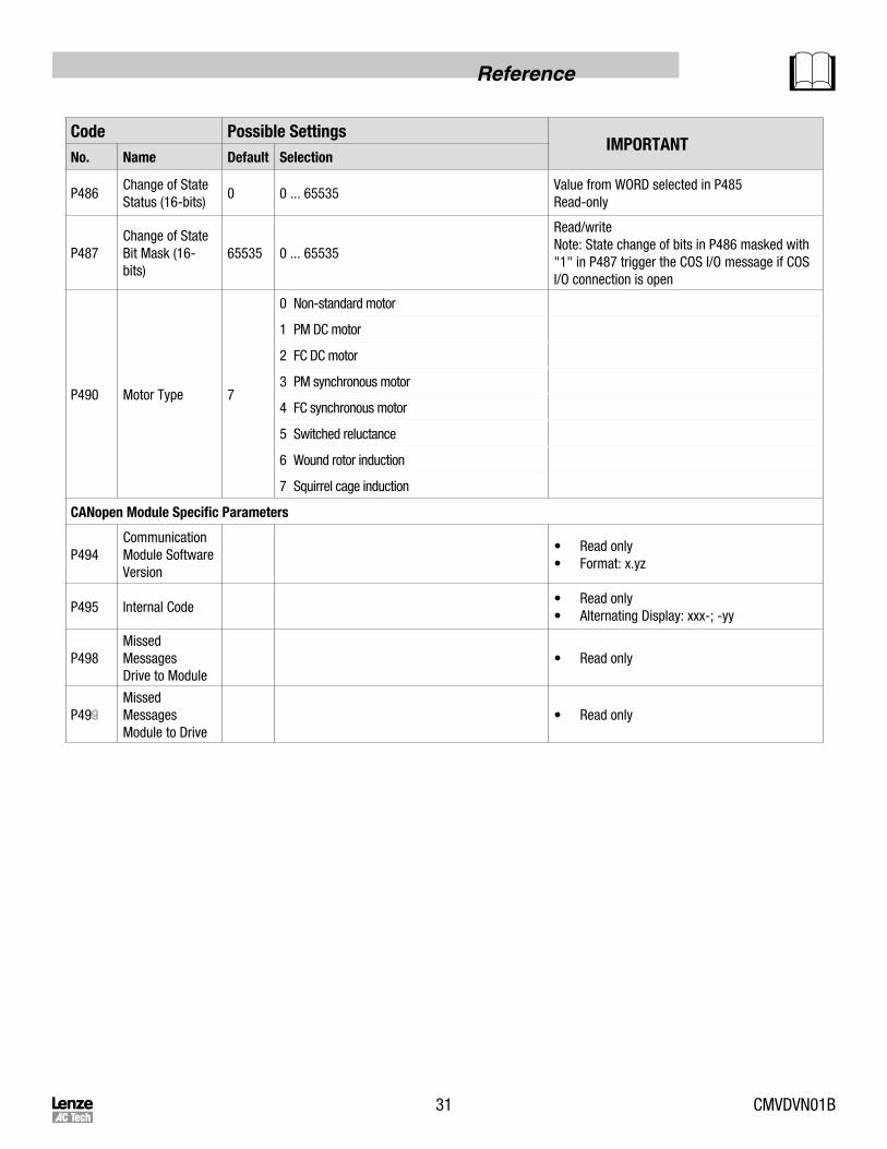
P486Change of StateStatus (16-bits)
0 0 ... 65535Value from WORD selected in P485Read-only
P487Change of StateBit Mask (16-bits)
65535 0 ... 65535
Read/writeNote: State change of bits in P486 masked with "1" in P487 trigger the COS I/O message if COS I/O connection is open
P490 Motor Type 7
0 Non-standard motor
1 PM DC motor
2 FC DC motor
3 PM synchronous motor
4 FC synchronous motor
5 Switched reluctance
6 Wound rotor induction
7 Squirrel cage induction
CANopenModuleSpecificParameters
P494CommunicationModule Software Version
• Read only• Format: x.yz
P495 Internal Code• Read only• Alternating Display: xxx-; -yy
P498MissedMessagesDrive to Module
• Read only
P49MissedMessagesModule to Drive
• Read only

CMVDVN01B 32
Reference
7.2 ClassImplementationDetails7.2.1 IdentityObject-Class0x01
IDENTITYCLASSATTRIBUTES
ATTRIBUTEID ACCESSRULE NAME DATATYPE VALUE
INSTANCE 0
1 GET REVISION UINT 1
INSTANCE 1
1 GET VENDOR ID UINT 587
2 GET DEVICE TYPE UINT 2 (AC drive)
3 GET PRODUCT CODE UINT 2 (SMV DeviceNet Module)
4 GETMAJOR REV.MINOR REV.
USINTUSINT
11
5 GET STATUS USINT4 = Configured5 = Owned
6 GET SERIAL NUMBER UDINT Unique 32-bit number
7 GET PRODUCT NAME ASCII String “AC Tech SMV Communication Module Drive”
IDENTITYCLASSSERVICES
SERVICE CODE IMPLEMENTED FOR SERVICE NAME
CLASS INSTANCE
0x0E YES YES Get_Attribute_Single
0x05 NO YES RESET
7.2.2 MessageRouterObject-Class0x02
MESSAGEROUTERCLASSATTRIBUTES
ATTRIBUTEID ACCESSRULE NAME DATATYPE VALUE
INSTANCE 0
1 GET REVISION UINT 1
INSTANCE 1
1 GET CLASS LIST ARRAY List of Implemented Classes
2 GET MAXIMUM NUMBER OF CONNECTIONS UINT 1
3 GET CURRENTLY USED CONNECTIONS UINT 1
4 GET CURRENTLY USED ID’s Array of UINT List of Connection ID
MESSAGEROUTERCLASSSERVICES
SERVICE CODE IMPLEMENTED FOR SERVICE NAME
CLASS INSTANCE
0x0E YES YES Get_Attribute_Single

33 CMVDVN01B
Reference
7.2.3 DeviceNetObject-Class0x03
DEVICENETCLASSATTRIBUTES
ATTRIBUTEID ACCESSRULE NAME DATATYPE VALUE
INSTANCE 0
1 GET REVISION UINT 2
INSTANCE 1
1 GET/SET NODE ADDRESS USINT 0 to 63
2 GET/SET DATA RATE USINT 0 to 2
3 GET/SET BOI BOOL 0 = Hold in Error
1 = Reset CAN
4 GET/SET BUS-OFF COUNTER USINT 0 to 255
5 GET ALLOCATION INFO
ALLOC. CHOICE BYTE Allocation Byte
MASTER ADDRESS USINT 0 to 63 Address
DEVICENETCLASSSERVICES
SERVICE CODE IMPLEMENTED FOR SERVICE NAME
CLASS INSTANCE
0x0E YES YES Get_Attribute_Single
0x10 NO YES Set_Attribute_Single
0x4B NO YES Allocate_Master/Slave_Connection_Set
0x4C NO YES Release_Master/Slave_Connection_Set

CMVDVN01B 34
Reference
7.2.4 AssemblyObject-Class0x04
ASSEMBLYCLASSATTRIBUTES
ATTRIBUTEID ACCESSRULE NAME DATATYPE VALUE
INSTANCE 0
1 GET REVISION UINT 2
2 GET MAXIMUM NUMBER OF INSTANCES USINT 11
INSTANCES (See Below)
1 GET NUMBER OF MEMBER USINT 1
3 GET/SET DATA INSTANCE
INSTANCENUMBERANDNAME ACCESSRULEFORATTRIBUTE#3DATA
INSTANCE 20 = BASIC SPEED CONTROL GET / SET
INSTANCE 21 = EXTENDED SPEED CONTROL GET / SET
INSTANCE 100 = EXTENDED SPEED HZ + DIGITAL AND ANALOG OUTPUT GET / SET
INSTANCE 102 = PID SETPOINT + DIGITAL AND ANALOG OUTPUT GET / SET
INSTANCE 104 = TORQUE SETPOINT + DIGITAL AND ANALOG OUTPUT GET / SET
INSTANCE 70 = BASIC SPEED CONTROL GET
INSTANCE 71 = EXTENDED SPEED CONTROL GET
INSTANCE 101 = EXTENDED SPEED HZ + ANALOG AND DIGITAL I/O GET
INSTANCE 103 = CUSTOM: SPEED, PID SETPOINT, FEEDBACK GET
INSTANCE 105 = CUSTOM: SPEED, ACTUAL TORQUE, ANALOG INPUT GET
INSTANCE 106 = CUSTOM: DATA WORDS SELECTABLE WITH PARAMETERS P441 - P444 GET
ASSEMBLYCLASSSERVICES
SERVICE CODE IMPLEMETED FOR SERVICE NAME
CLASS INSTANCE
0x0E YES YES Get_Attribute_Single
0x05 NO YES RESET

35 CMVDVN01B
Reference
7.2.5 DeviceNetConnectionObject-Class0x05
DEVICENETCONNECTIONCLASSATTRIBUTES
ATTRIBUTEID ACCESSRULE NAME DATATYPE VALUE
INSTANCE 0
1 GET REVISION UINT 1
INSTANCE 1 - EXPLICIT MESSAGE INSTANCE
1 GET STATE USINT
0 = Nonexistent1 = Configuring3 = Established4 = Timed Out5 = Deferred Delete
2 GET INSTANCE TYPE USINT 0 = Explicit
3 GET TRANSPORT CLASS TRIGGER USINT 0x83
4 GET PRODUCED CONNECTION ID UINT
5 GET CONSUMED CONNECTION ID UINT
6 GET INITIAL COMM. CHARACTERISTICS USINT 0x22
7 GET PRODUCED CONNECTION SIZE UINT 80 (max)
8 GET CONSUMED CONNECTION SIZE UINT 80 (max)
9 GET / SET EXPECTED PACKET RATE UINT Timer Resolution of 2 ms
12 GET / SET WATCHDOG ACTION UINT1 = Auto Delete3 = Deferred Delete
13 GET PRODUCED CONN. PATH LENGTH UINT 0
14 GET PRODUCED CONNECTION PATH Null (No Data)
15 GET CONSUMED CONN. PATH LENGTH UINT 0
16 GET CONSUMED CONNECTION PATH Null (No Data)
17 GET INHIBIT TIME USINT 0

CMVDVN01B 36
Reference
DEVICENETCONNECTIONCLASSATTRIBUTES
ATTRIBUTEID ACCESSRULE NAME DATATYPE VALUE
INSTANCE 2 - POLLED I/O MESSAGE CONNECTION
1 GET STATE USINT
0 = Nonexistent1 = Configuring3 = Established4 = Timed Out
2 GET INSTANCE TYPE USINT 1 = I/O Connection
3 GETTRANSPORT CLASSTRIGGER
USINT 0x82
4 GETPRODUCEDCONNECTION ID
UINT
5 GETCONSUMEDCONNECTION ID
UINT
6 GETINITIAL COMM.CHARACTERISTICS
USINT 0x01
7 GETPRODUCEDCONNECTION SIZE
UINT 0 to 8
8 GETCONSUMEDCONNECTION SIZE
UINT 0 to 4
9 GET / SETEXPECTED PACKET RATE
UINT Timer Resolution of 2 ms
12 GET / SET WATCHDOG ACTION UINT0 = Time Out1 = Auto Delete2 = Auto Reset
13 GETPRODUCED CONN.PATH LENGTH
UINT 3
14 GETPRODUCEDCONNECTION PATH
0x63 (Hex String)Hex String - Assembly #
15 GETCONSUMED CONN.PATH LENGTH
UINT 3
16 GETCONSUMEDCONNECTION PATH
0x63 (Hex String)Hex String - Assembly #
17 GET INHIBIT TIME USINT 0

37 CMVDVN01B
Reference
DEVICENETCONNECTIONCLASSATTRIBUTES
ATTRIBUTEID ACCESSRULE NAME DATATYPE VALUE
INSTANCE 3 - BIT STROBE
1 GET STATE USINT 0 = Nonexistent1 = Configuring3 = Established4 = Timed Out
2 GET INSTANCE TYPE USINT 1 = I/O Connection
3 GET TRANSPORT CLASSTRIGGER
USINT 0x82
4 GET PRODUCEDCONNECTION ID
UINT
5 GET CONSUMEDCONNECTION ID
UINT
6 GET INITIAL COMM.CHARACTERISTICS
USINT 0x02
7 GET PRODUCEDCONNECTION SIZE
UINT 0 to 8
8 GET CONSUMEDCONNECTION SIZE
UINT 8
9 GET / SET EXPECTED PACKET RATE
UINT Timer Resolution of 2 ms
12 GET / SET WATCHDOG ACTION UINT 0 = Time Out1 = Auto Delete2 = Auto Reset
13 GET PRODUCED CONN.PATH LENGTH
UINT 3
14 GET PRODUCEDCONNECTION PATH
0x63 (Hex String)Hex String - Assembly #
15 GET CONSUMED CONN.PATH LENGTH
UINT 3
16 GET CONSUMEDCONNECTION PATH
0x63 (Hex String)Hex String - Assembly #
17 GET INHIBIT TIME USINT 0
CMVDVN01B 38
Reference
DEVICENETCONNECTIONCLASSATTRIBUTES
ATTRIBUTEID ACCESSRULE NAME DATATYPE VALUE
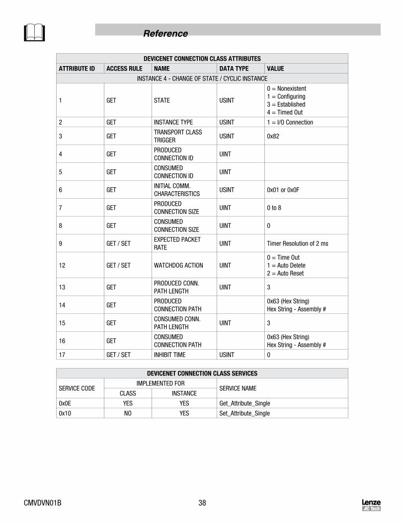
INSTANCE 4 - CHANGE OF STATE / CYCLIC INSTANCE
1 GET STATE USINT
0 = Nonexistent1 = Configuring3 = Established4 = Timed Out
2 GET INSTANCE TYPE USINT 1 = I/O Connection
3 GETTRANSPORT CLASSTRIGGER
USINT 0x82
4 GETPRODUCEDCONNECTION ID
UINT
5 GETCONSUMEDCONNECTION ID
UINT
6 GETINITIAL COMM.CHARACTERISTICS
USINT 0x01 or 0x0F
7 GETPRODUCEDCONNECTION SIZE
UINT 0 to 8
8 GETCONSUMEDCONNECTION SIZE
UINT 0
9 GET / SETEXPECTED PACKET RATE
UINT Timer Resolution of 2 ms
12 GET / SET WATCHDOG ACTION UINT0 = Time Out1 = Auto Delete2 = Auto Reset
13 GETPRODUCED CONN.PATH LENGTH
UINT 3
14 GETPRODUCEDCONNECTION PATH
0x63 (Hex String)Hex String - Assembly #
15 GETCONSUMED CONN.PATH LENGTH
UINT 3
16 GETCONSUMEDCONNECTION PATH
0x63 (Hex String)Hex String - Assembly #
17 GET / SET INHIBIT TIME USINT 0
DEVICENETCONNECTIONCLASSSERVICES
SERVICE CODEIMPLEMENTED FOR
SERVICE NAMECLASS INSTANCE
0x0E YES YES Get_Attribute_Single
0x10 NO YES Set_Attribute_Single
39 CMVDVN01B
Reference
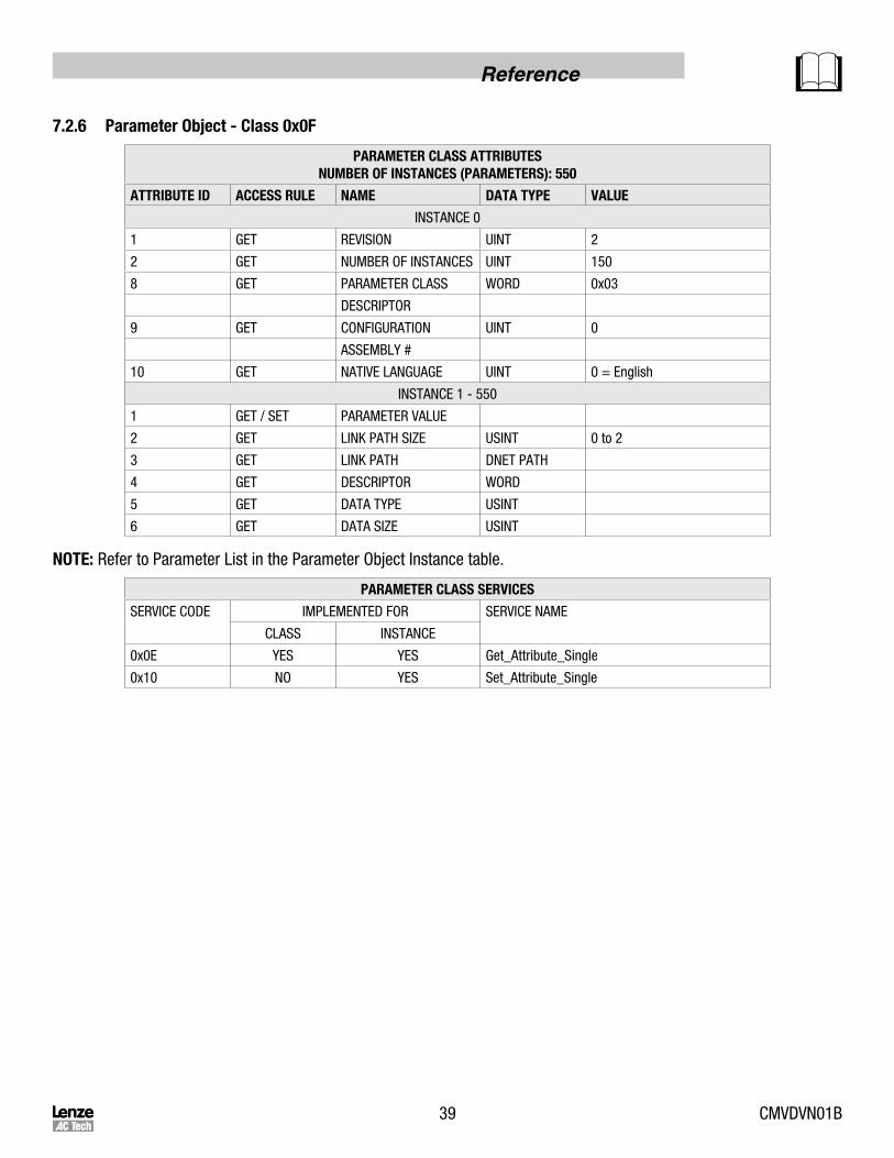
7.2.6 ParameterObject-Class0x0F
PARAMETERCLASSATTRIBUTESNUMBEROFINSTANCES(PARAMETERS):550
ATTRIBUTEID ACCESSRULE NAME DATATYPE VALUE
INSTANCE 0
1 GET REVISION UINT 2
2 GET NUMBER OF INSTANCES UINT 150
8 GET PARAMETER CLASS WORD 0x03
DESCRIPTOR
9 GET CONFIGURATION UINT 0
ASSEMBLY #
10 GET NATIVE LANGUAGE UINT 0 = English
INSTANCE 1 - 550
1 GET / SET PARAMETER VALUE
2 GET LINK PATH SIZE USINT 0 to 2
3 GET LINK PATH DNET PATH
4 GET DESCRIPTOR WORD
5 GET DATA TYPE USINT
6 GET DATA SIZE USINT
NOTE:Refer to Parameter List in the Parameter Object Instance table.
PARAMETERCLASSSERVICES
SERVICE CODE IMPLEMENTED FOR SERVICE NAME
CLASS INSTANCE
0x0E YES YES Get_Attribute_Single
0x10 NO YES Set_Attribute_Single

CMVDVN01B 40
Reference
Parameter Object Instance (Parameter List)NOTE: These same parameters are present in the EDS File
IDNO PARAMETER OBJECTMAPPING
1-49 RESERVED
50 DIGITAL OUTPUT BITS 0x0F-50-1
51-54 RESERVED
55 TB30 ANALOG OUTPUT 0x0F-55-1
56-59 RESERVED
60 KEYPAD COMMAND FREQUENCY 0x0F-60-1
61 NETWORK COMMAND FREQUENCY 0x0F-61-1
62 ACTUAL COMMAND FREQUENCY 0x0F-62-1
63 ACTUAL OUTPUT FREQUENCY 0x0F-63-1
64 RESERVED
65 CONTROL WORD 0x0F-65-1
66 DEVICENET STATUS WORD 0x0F-66-1
67 DRIVE STATUS WORD 0x0F-67-1
68 DRIVE OPERATION STATE 0x0F-68-1
69 PRESENT FAULT 0x0F-69-1
70 KEYPAD PID SETPOINT COMMAND 0x0F-70-1
71 NETWORK PID SETPOINT COMMAND 0x0F-71-1
72 ACTUAL PID SETPOINT 0x0F-72-1
73 ACTUAL PID SETPOINT 0x0F-73-1
74 ACTUAL PID FEEDBACK 0x0F-74-1
75-79 RESERVED
80 KEYPAD TORQUE SETPOINT (%) 0x0F-80-1
81 NETWORK TORQUE SETPOINT (%) 0x0F-81-1
82-90 RESERVED
91 INTERNAL STATE FGD 0x0F-91-1
92 INTERNAL STATE PWM 0x0F-92-1
93-98 RESERVED
99 DRIVE PARAMETER REVISION 0x0F-99-1
100-541 MATCH SMV PARAMETERS P100 TO P541
542-550 RESERVED
41 CMVDVN01B
Reference
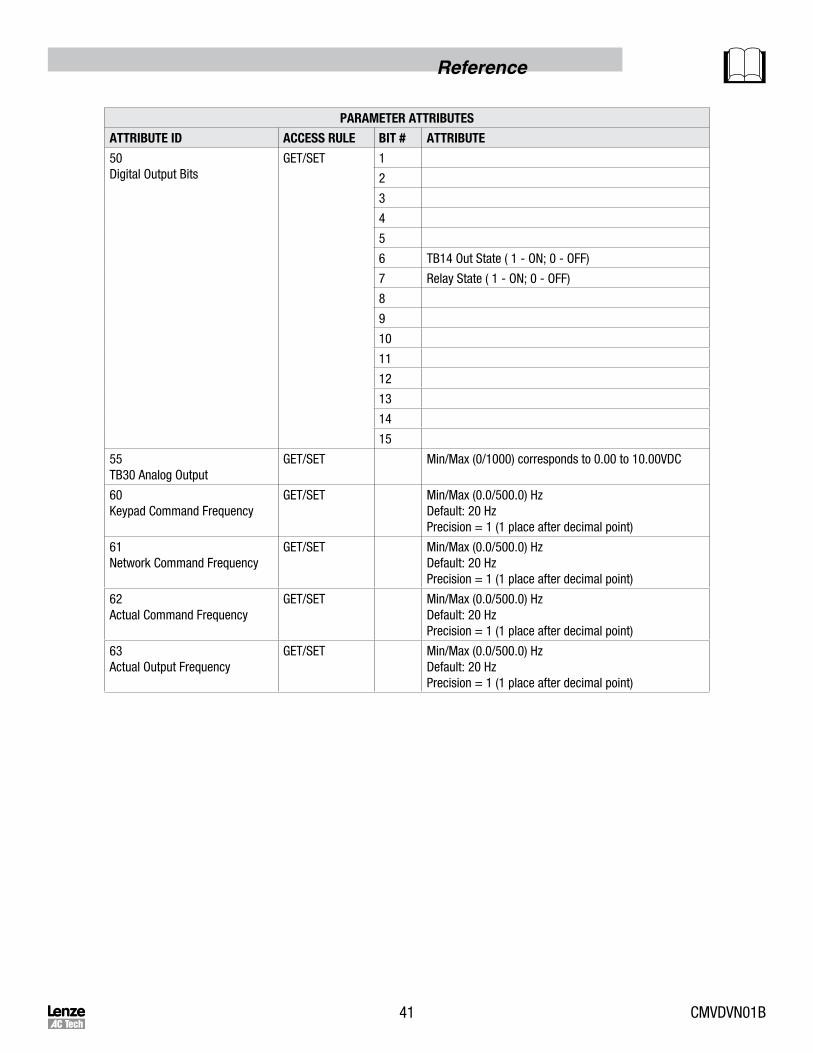
PARAMETERATTRIBUTES
ATTRIBUTEID ACCESSRULE BIT# ATTRIBUTE
50Digital Output Bits
GET/SET 1
2
3
4
5
6 TB14 Out State ( 1 - ON; 0 - OFF)
7 Relay State ( 1 - ON; 0 - OFF)
8
9
10
11
12
13
14
15
55TB30 Analog Output
GET/SET Min/Max (0/1000) corresponds to 0.00 to 10.00VDC
60Keypad Command Frequency
GET/SET Min/Max (0.0/500.0) Hz Default: 20 HzPrecision = 1 (1 place after decimal point)
61Network Command Frequency
GET/SET Min/Max (0.0/500.0) Hz Default: 20 HzPrecision = 1 (1 place after decimal point)
62Actual Command Frequency
GET/SET Min/Max (0.0/500.0) Hz Default: 20 HzPrecision = 1 (1 place after decimal point)
63Actual Output Frequency
GET/SET Min/Max (0.0/500.0) Hz Default: 20 HzPrecision = 1 (1 place after decimal point)
CMVDVN01B 42
Reference
PARAMETERATTRIBUTES
ATTRIBUTEID ACCESSRULE BIT# ATTRIBUTE
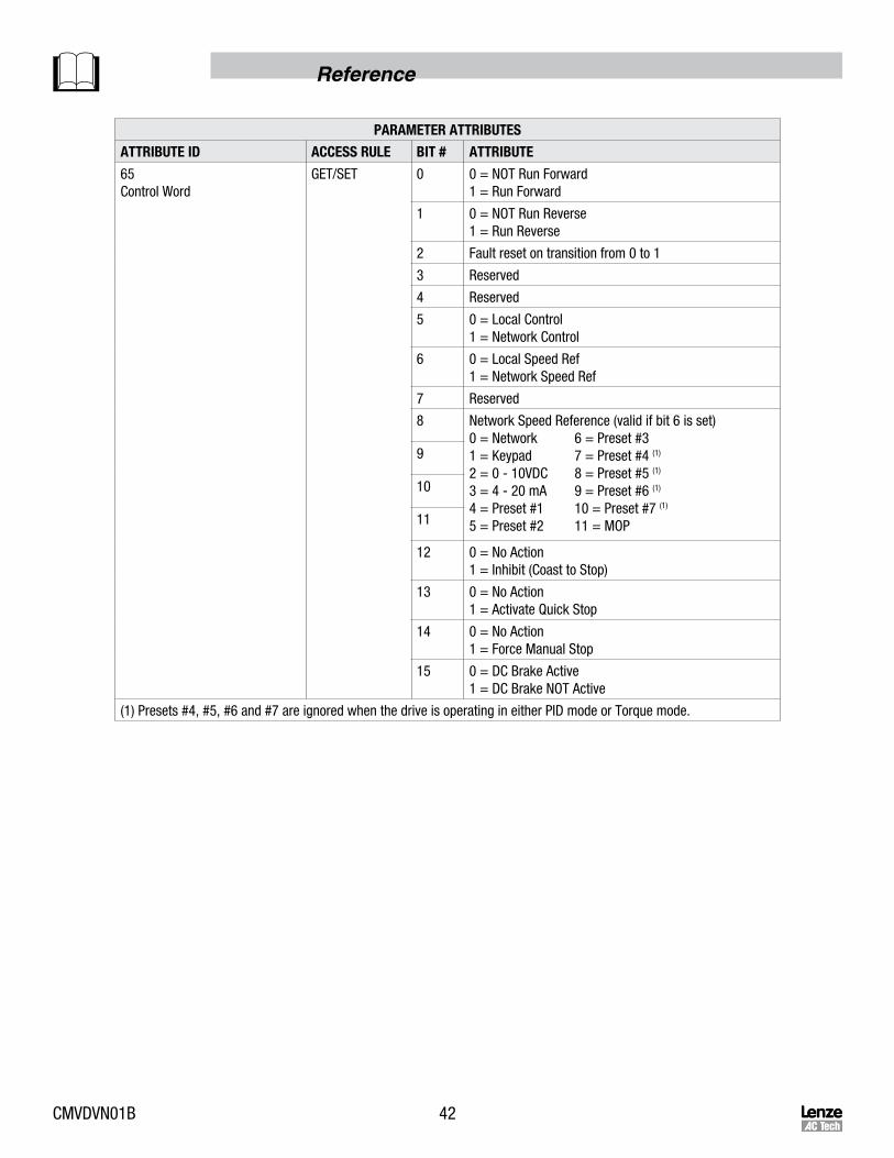
65Control Word
GET/SET 0 0 = NOT Run Forward1 = Run Forward
1 0 = NOT Run Reverse1 = Run Reverse
2 Fault reset on transition from 0 to 1
3 Reserved
4 Reserved
5 0 = Local Control1 = Network Control
6 0 = Local Speed Ref1 = Network Speed Ref
7 Reserved
8 Network Speed Reference (valid if bit 6 is set) 0 = Network 6 = Preset #31 = Keypad 7 = Preset #4 (1)
2 = 0 - 10VDC 8 = Preset #5 (1)
3 = 4 - 20 mA 9 = Preset #6 (1)
4 = Preset #1 10 = Preset #7 (1)
5 = Preset #2 11 = MOP
9
10
11
12 0 = No Action1 = Inhibit (Coast to Stop)
13 0 = No Action1 = Activate Quick Stop
14 0 = No Action1 = Force Manual Stop
15 0 = DC Brake Active1 = DC Brake NOT Active
(1) Presets #4, #5, #6 and #7 are ignored when the drive is operating in either PID mode or Torque mode.
43 CMVDVN01B
Reference
PARAMETERATTRIBUTES
ATTRIBUTEID ACCESSRULE BIT# ATTRIBUTE
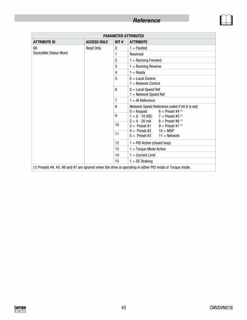
66DeviceNet Status Word
Read Only 0 1 = Faulted
1 Reserved
2 1 = Running Forward
3 1 = Running Reverse
4 1 = Ready
5 0 = Local Control1 = Network Control
6 0 = Local Speed Ref1 = Network Speed Ref
7 1 = At Reference
8 Network Speed Reference (valid if bit 6 is set)0 = Keypad 6 = Preset #4 (1)
1 = 0 - 10 VDC 7 = Preset #5 (1)
2 = 4 - 20 mA 8 = Preset #6 (1)
3 = Preset #1 9 = Preset #7 (1)
4 = Preset #2 10 = MOP5 = Preset #3 11 = Network
9
10
11
12 1 = PID Active (closed loop)
13 1 = Torque Mode Active
14 1 = Current Limit
15 1 = DC Braking
(1) Presets #4, #5, #6 and #7 are ignored when the drive is operating in either PID mode or Torque mode.

CMVDVN01B 44
Reference
PARAMETERATTRIBUTES
ATTRIBUTEID ACCESSRULE BIT# ATTRIBUTE
67Drive Status Word
Read Only 0 0 = Stop1 = Run
1 1 = Quick Stop (ramp to stop) Active
2 0 = Direction Forward (commanded)1 = Direction Reverse
3 0 = Direction Forward (actual)1 = Direction Reverse
4 0 = NET REF not active1 = NET REF sets the active source
5 0 = Speed Mode1 = Torque Mode
6 0 = Open Loop (PID Off)1 = Closed Loop (PID On)
7 0 = Manual Mode; 1 = AUTO mode
8 Actual Setpoint Source 0 = Keypad 6 = Preset #41 = 0 - 10 VDC 7 = Preset #52 = 4 - 20 mA 8 = Preset #63 = Preset #1 9 = Preset #74 = Preset #2 10 = MOP5 = Preset #3 11 = Network
9
10
11
12
13 Control0 = Keypad 2 = Remote Keypad1 = Terminal 3 = Network
14 0 = Network Control Disabled1 = Network Control Enabled
15 1 = DC Braking
68Drive Operation State
AC Tech Diagnostics Only

45 CMVDVN01B
Reference
PARAMETERATTRIBUTES
ATTRIBUTEID ACCESSRULE BIT# ATTRIBUTE
69Present Fault
Read Only 1 Temperature Output Fault
2 Overcurrent Fault
3 Ground (Short to Earth) Fault
4 Excessive Drive Temperature Fault
5 Fly Start Fault
6 High Bus Voltage (Over Voltage) Fault
7 Low Bus Voltage Fault
8 Motor Overload Fault
9 OEM Defaults Corrupted
10 Illegal Setup Fault
11 Dynamic Brake Overheated Fault
12 Single Phase, Voltage Ripple to High
13 External Fault
14 Control EEPROM fault
15 Start Power Loss Fault
16 Incompatibility Fault
17 EEPROM Hardware Failure
18 Internal Fault (Edge Over Run)
19 Internal Fault (PWM Over Run)
20 Stack Overflow Fault
21 Stack Underflow Fault
22 Internal Fault (BGD Missing)
23 Watchdog Timeout Fault
24 Illegal OPCO Fault
25 Illegal Address Fault
26 Drive Hardware Fault
27 Internal Fault (AD Offset)
28 Internal Fault (RKPD Lost)
29 Assertion Level switched during operation Fault
30 Internal Fault (FGD Missing)
31 Internal Fault (PW Missing)
32 Current Loop Fault
33 Internal communication from JK1 Lost Fault

CMVDVN01B 46
Reference
PARAMETERATTRIBUTES
ATTRIBUTEID ACCESSRULE BIT# ATTRIBUTE
69Present Fault(continued)
34 Internal Fault (Module Communication (SPI) Timeout)
35 Internal Fault (FNR: Invalid Message Received)
36 Network Fault #1
37 Network Fault #2
38 Network Fault #3
39 Network Fault #4
40 Network Fault #5
41 Network Fault #6
42 Network Fault #7
43 Network Fault #8
44 Network Fault #9
70Keypad PID Setpoint Command
GET/SET Min: -99.9Max: 3100.0Default = 0Precision = 1 (1 place after decimal point)
71Network PID Setpoint Command
GET/SET Min: -99.9Max: 3100.0Default = 0Precision = 1 (1 place after decimal point)
72Actual PID Setpoint
Read Only Min: -99.9Max: 3100.0Default = 0Precision = 1 (1 place after decimal point)
73Actual PID Setpoint
Read Only Min: -99.9Max: 3100.0Default = 0Precision = 1 (1 place after decimal point)
74Actual PID Feedback
Read Only Min: -99.9Max: 3100.0Default = 0Precision = 1 (1 place after decimal point)
80Keypad Torque Setpoint (%)
GET/SET Min: 0[%]Max: 400[%]Default = 0Precision = 0
81Network Torque Setpoint (%)
GET/SET Min: 0[%]Max: 400[%]Default = 0Precision = 0
91Internal State FGD
AC Tech Diagnostics Only
92Internal State PWM
AC Tech Diagnostics Only

47 CMVDVN01B
Reference
7.2.7 ParameterGroupObject-Class0x10
PARAMETERGROUPCLASSATTRIBUTES
ATTRIBUTEID ACCESSRULE NAME DATATYPE VALUE
INSTANCE 0
1 GET REVISION UINT 1
2 GET NUMBER OF INSTANCES UINT 4
8 GET NATIVE LANGUAGE UINT 0 = English
INSTANCE 1 - 3
1 GET GROUP NAME SHORT STRING
2 GETNUMBER OF MEMBERSIN THE GROUP
UINT
3 GET1st PARAMETER IN THE GROUP
UINT
4 GET2nd PARAMETERIN THE GROUP
UINT
n GET(n-2) th PARAMETERIN THE GROUP
UINT
7.2.8 MotorDataObject-Class0x28
MOTORGROUPCLASSATTRIBUTES
ATTRIBUTEID ACCESSRULE NAME DATATYPE VALUE
INSTANCE 0
1 GET REVISION UINT 1
2 GET NUMBER OF INSTANCES UINT 1
INSTANCE 1
1 GETNUMBER OF SUPPORTEDATTRIBUTES
USINT 7
2 GET ATTRIBUTE LIST ARRAY
3 GET/SET MOTOR TYPE USINT 0 - 10
6 GET/SET RATED CURRENT UINT RATED STATOR CURRENT (0.1A)
7 GET/SET RATED VOLTAGE UINT RATED BASE VOLTAGE (V)
9 GET/SET RATED FREQUENCY UNIT RATED FREQUENCY (Hz)
11 GET/SETNOMINAL SPEED AT RATED FREQUENCY
UNIT NOMINAL SPEED (RPM)
MOTORDATACLASSSERVICES
SERVICE CODE IMPLEMENTED FOR SERVICE NAME
CLASS INSTANCE
0x0E YES YES GET_ATTRIBUTE_SINGLE
0x10 NO YES SET_ATTRIBUTE_SINGLE
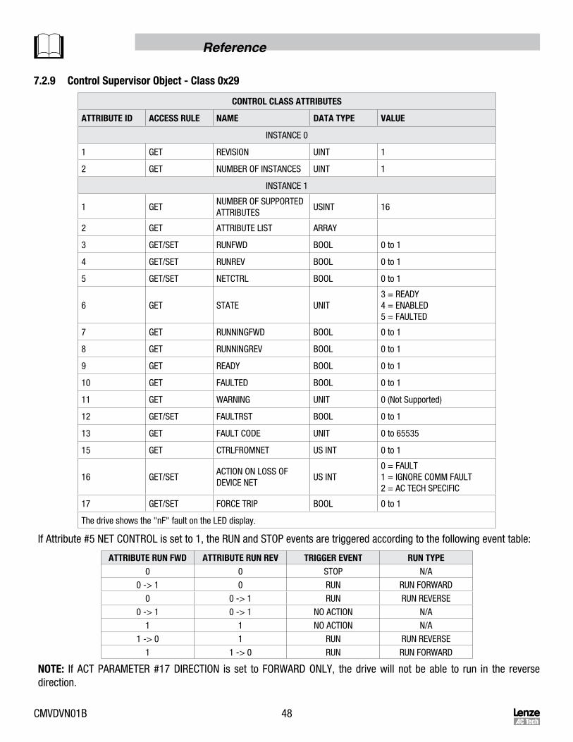
CMVDVN01B 48
Reference
7.2.9 ControlSupervisorObject-Class0x29
CONTROLCLASSATTRIBUTES
ATTRIBUTEID ACCESSRULE NAME DATATYPE VALUE
INSTANCE 0
1 GET REVISION UINT 1
2 GET NUMBER OF INSTANCES UINT 1
INSTANCE 1
1 GETNUMBER OF SUPPORTED ATTRIBUTES
USINT 16
2 GET ATTRIBUTE LIST ARRAY
3 GET/SET RUNFWD BOOL 0 to 1
4 GET/SET RUNREV BOOL 0 to 1
5 GET/SET NETCTRL BOOL 0 to 1
6 GET STATE UNIT3 = READY4 = ENABLED5 = FAULTED
7 GET RUNNINGFWD BOOL 0 to 1
8 GET RUNNINGREV BOOL 0 to 1
9 GET READY BOOL 0 to 1
10 GET FAULTED BOOL 0 to 1
11 GET WARNING UNIT 0 (Not Supported)
12 GET/SET FAULTRST BOOL 0 to 1
13 GET FAULT CODE UNIT 0 to 65535
15 GET CTRLFROMNET US INT 0 to 1
16 GET/SETACTION ON LOSS OF DEVICE NET
US INT0 = FAULT1 = IGNORE COMM FAULT2 = AC TECH SPECIFIC
17 GET/SET FORCE TRIP BOOL 0 to 1
The drive shows the "nF" fault on the LED display.
If Attribute #5 NET CONTROL is set to 1, the RUN and STOP events are triggered according to the following event table:
ATTRIBUTERUNFWD ATTRIBUTERUNREV TRIGGEREVENT RUNTYPE0 0 STOP N/A
0 -> 1 0 RUN RUN FORWARD
0 0 -> 1 RUN RUN REVERSE
0 -> 1 0 -> 1 NO ACTION N/A
1 1 NO ACTION N/A
1 -> 0 1 RUN RUN REVERSE
1 1 -> 0 RUN RUN FORWARD
NOTE: If ACT PARAMETER #17 DIRECTION is set to FORWARD ONLY, the drive will not be able to run in the reverse direction.
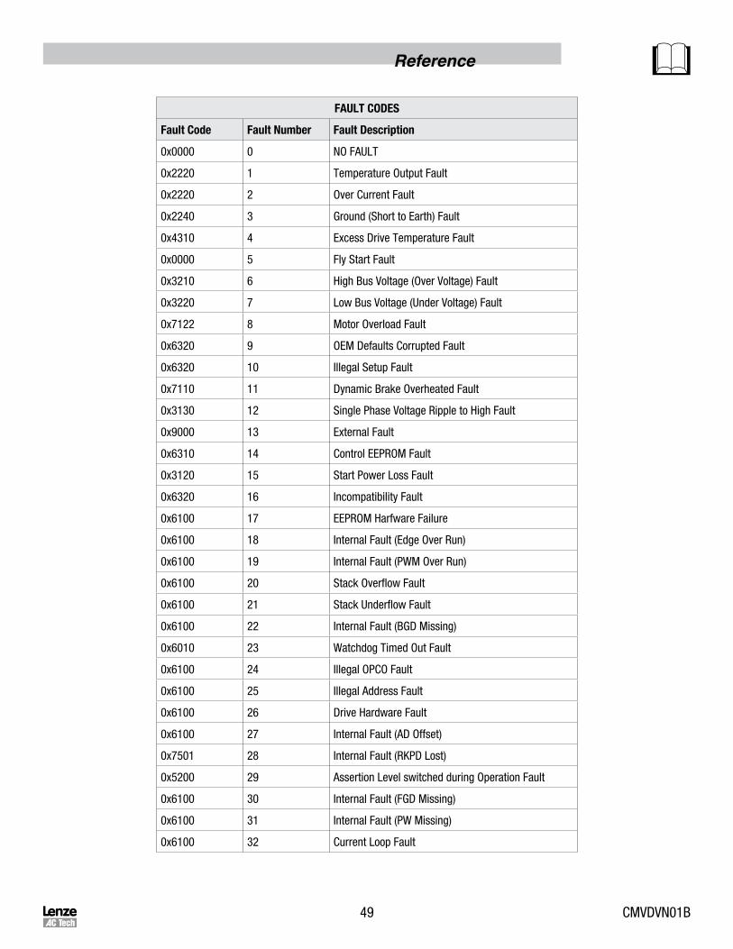
49 CMVDVN01B
Reference
FAULTCODES
FaultCode FaultNumber FaultDescription
0x0000 0 NO FAULT
0x2220 1 Temperature Output Fault
0x2220 2 Over Current Fault
0x2240 3 Ground (Short to Earth) Fault
0x4310 4 Excess Drive Temperature Fault
0x0000 5 Fly Start Fault
0x3210 6 High Bus Voltage (Over Voltage) Fault
0x3220 7 Low Bus Voltage (Under Voltage) Fault
0x7122 8 Motor Overload Fault
0x6320 9 OEM Defaults Corrupted Fault
0x6320 10 Illegal Setup Fault
0x7110 11 Dynamic Brake Overheated Fault
0x3130 12 Single Phase Voltage Ripple to High Fault
0x9000 13 External Fault
0x6310 14 Control EEPROM Fault
0x3120 15 Start Power Loss Fault
0x6320 16 Incompatibility Fault
0x6100 17 EEPROM Harfware Failure
0x6100 18 Internal Fault (Edge Over Run)
0x6100 19 Internal Fault (PWM Over Run)
0x6100 20 Stack Overflow Fault
0x6100 21 Stack Underflow Fault
0x6100 22 Internal Fault (BGD Missing)
0x6010 23 Watchdog Timed Out Fault
0x6100 24 Illegal OPCO Fault
0x6100 25 Illegal Address Fault
0x6100 26 Drive Hardware Fault
0x6100 27 Internal Fault (AD Offset)
0x7501 28 Internal Fault (RKPD Lost)
0x5200 29 Assertion Level switched during Operation Fault
0x6100 30 Internal Fault (FGD Missing)
0x6100 31 Internal Fault (PW Missing)
0x6100 32 Current Loop Fault

CMVDVN01B 50
Reference
FAULTCODES
FaultCode FaultNumber FaultDescription
0x7500 33 Internal Communication from JK1 Lost Fault
0x7501 34 Internal Fault (Module Communication (SPI) Timeout)
0x7502 35 Internal Fault (FNR: Invalid Message Received)
0x7511 36 Network Fault #1
0x7512 37 Network Fault #2
0x7513 38 Network Fault #3
0x7514 39 Network Fault #4
0x7515 40 Network Fault #5
0x7516 41 Network Fault #6
0x7517 42 Network Fault #7
0x7518 43 Network Fault #8
0x7519 44 Network Fault #9
0x1000 46 - 50 RESERVED
CONTROLSUPERVISORCLASSSERVICES
Service Code Implemented For Service Name
Class Instance
0x0E YES YES Get_Attribute_Single
0x10 NO YES Set_Attribute_Single

51 CMVDVN01B
Reference
7.2.10 AC/DCDriveObject-Class0x2A
AC/DCDRIVECLASSATTRIBUTES
AttributeID AccessRule Name DataType Value
INSTANCE 0
1 GET REVISION UINT 1
2 GET NUMBER OF INSTANCES UINT 1
INSTANCE 1
1 GET NO. OF SUPPORTED ATTRIBUTES USINT 12
2 GET ATRIBUTE LIST ARRAY
3 GET AT REFERENCE BOOL Speed AtRef
4 GET/SET NET REFERENCE BOOL0 = Local SpdRef1 = Net SpdRef
6 GET DRIVE MODE USINT
1 = Open Loop Spd Control2 = Vector Mode3 = Torque Mode4 = PID Mode
7 GET ACTUAL SPEED INT Actual Speed (RPM)
8 GET/SET SPEED REFERENCE INT Speed Reference (RPM)
9 GET MOTOR PHASE CURRENT INT Actual Current (0.1A)
15 GET MOTOR PHASE CURRENT INT Actual Power (W)
16 GET INPUT VOLTAGE INT (V)
17 GET OUTPUT VOLTAGE IN (V)
29 GET STATUS OF SPEED REFERENCE INT0 = Local Spd Ref1 = Net Spd Ref
ACDRIVECLASSSERVICES
Service Code Implemented For Service Name
Class Instance
0x0E YES YES Get_Attribute_Single
0x10 NO YES Set_Attribute_Single
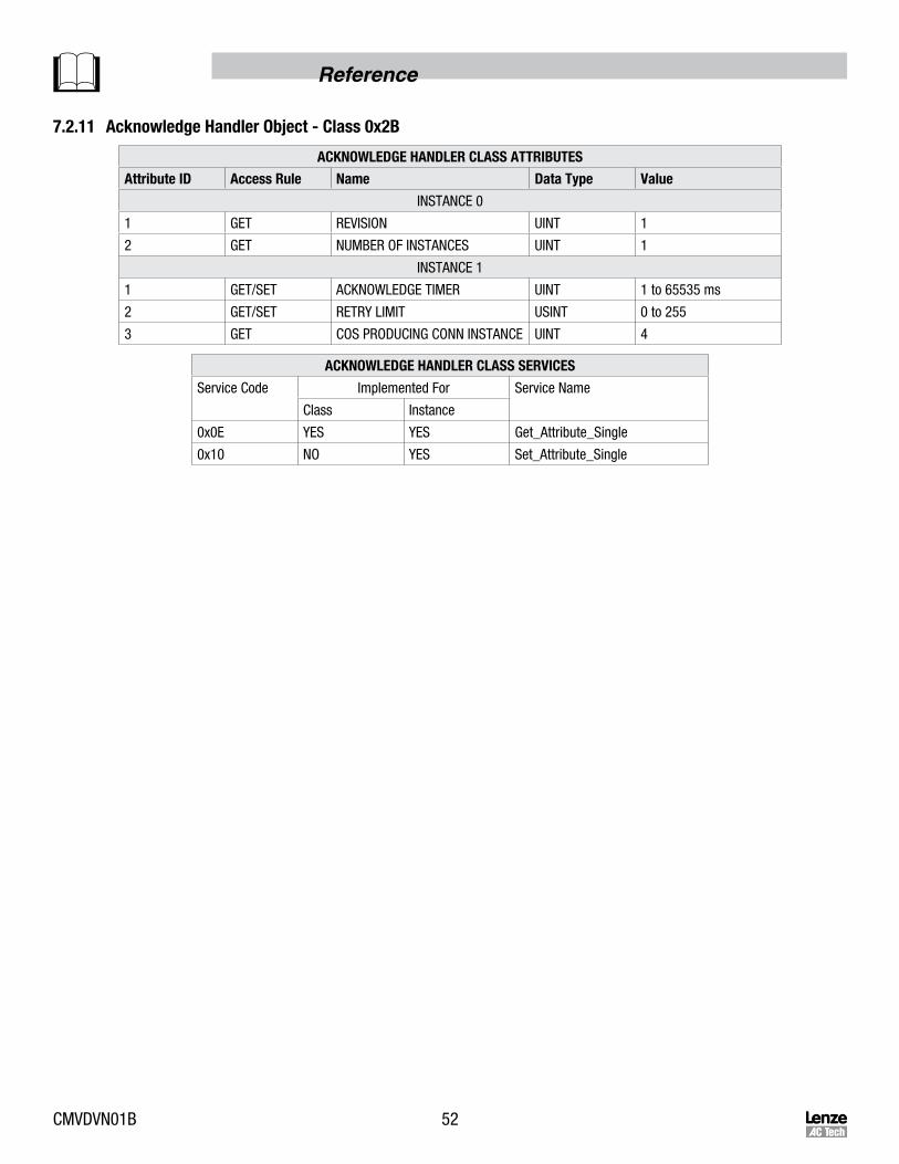
CMVDVN01B 52
Reference
7.2.11 AcknowledgeHandlerObject-Class0x2B
ACKNOWLEDGEHANDLERCLASSATTRIBUTES
AttributeID AccessRule Name DataType Value
INSTANCE 0
1 GET REVISION UINT 1
2 GET NUMBER OF INSTANCES UINT 1
INSTANCE 1
1 GET/SET ACKNOWLEDGE TIMER UINT 1 to 65535 ms
2 GET/SET RETRY LIMIT USINT 0 to 255
3 GET COS PRODUCING CONN INSTANCE UINT 4
ACKNOWLEDGEHANDLERCLASSSERVICES
Service Code Implemented For Service Name
Class Instance
0x0E YES YES Get_Attribute_Single
0x10 NO YES Set_Attribute_Single

53 CMVDVN01B

LenzeACTechCorporation630 Douglas Street • Uxbridge, MA • 01569 • USA
Sales: 800-217-9100 • Service: 508-278-9100www.lenzeamericas.com
CMVDVN01B-en1