smoke and heat control systems - tecnocupoletecnocupole.com/public/pdf en/enfssystem.pdfen...
TRANSCRIPT

TECNOCUPOLE PANCALDI SPA 39TECNOCUPOLE PANCALDI SPA 38
Smoke and heat control systems have the goal of eliminating and containing the spread of smoke and heat in the concerned ambient from fire by keeping a layer on the ground free of smoke.
These systems must be designed and produced in compliance with the UNI 9494 standard which distinguishes between two types of solutions:
• NSHESNATURAL smoke and heat exhaust systems
• SHEVSFORCED smoke and heat exhaust systems
SM
OK
E A
ND
HE
AT
C
ON
TR
OL
SY
ST
EM
S
In detail these systems pursue the following objectives:
• To keep exits and access to the areas affected by the fire free of smoke;
• To delay and/or prevent the conditions causing the fire to spread (“flash-over”);
• Ease fire-fighting intervention team operations;
• Limit damage to systems and goods;
• Reduce heat demand in the structures;
• Reduce damages caused by toxic or corrosive substances stemming from the combustion.
In the following pages the components for smoke and heat control will be shown, some of which are used in both natural and forced situations.

TECNOCUPOLE PANCALDI SPA 41TECNOCUPOLE PANCALDI SPA 40
1
2
3
4
5
6
7
8
9
10
11
12
COMMERCIAL NAME: Free smoke/ Free smoke plus / Free smoke + electric semi-frame for ventilation
SERIAL NUMBER: #######
FUNCTIONING: automatic / automatic + manual
THERMAL START UP TEMPERATURE 68° C / 93° C / 141° C / 182° C
USEFUL AERODYNAMIC SURFACE varies depending on the size of the device
RELIAILITY : RE50
OPENING UNDER LOAD
• SL 1000 if the geometric surface is less than or equal to 3 m2• SL 500 if the geometric surface is greater than or equal to 3 m2
LOW AMBIENT TEMPERATURE: T -25° C
WIND LOAD: WL 1500
HEAT RESISTANCE: B300
SKYLIGHT REACTION TO FIRE: • B-s1,d0 for polycarbonate• E for Plexiglas
SPOILER RESISTANCE: 10 Hz frequency
FREE SMOKE natural smoke and heat exhaust devices (NSHE), are one of the essential components in the natural exhaust system (NSHES).
In case of fire they allow to automatically open the skylights to extract the products generated by the combustion thus, contributing to keep a smoke free layer.
These devices can operate by temperature, via a sensor and a local energy source or by means of the equipment which can be connected to fire detection systems.
FREE SMOKE devices are designed and produced in compliance with the EN12101-2:2005 standard and CE certified under the provisions of Regulation 305/11 CE, DoP
NA
TU
RA
L S
MO
KE
AN
D H
EA
T
EX
HA
US
T D
EV
ICE
S:
FR
EE
SM
OK
E
12
3
124
5
6 7 8 9 10 11
The FREE SMOKE device is made up of a UNI6060 natural alloy extruded aluminium (see page 32) frame and counter frame, caulk assembled, complete with three –wing aluminium hinges and stainless steel screws and rivets.
The device is opened with a three section pneumatic telescopic cylinder which operates with a mix of CO2 / OIL pivoted between two parallel brackets, a cylinder containing CO2 gas, a thermo fusible glass tube set at 68° (different settings must be specified when ordering) and a thermal valve. A further spring latch cylinder blocks the system in closed state when there is no emergency.
The above mentioned latch cylinder can be undone to open the door for periodic maintenance. The system also allows to keep the opening position even in head winds of 10 m/sec. All the cylinder feed pipes provided are in Teflon protected by double stainless steel braiding.
The opening with controlled thrust up to full opening is also guaranteed in the presence of head winds. The device can be connected to a pneumatic type remote opening system (see page 53) without the need for other accessories.
NATURAL SMOKE AND HEAT EXHAUST DEVICES
FREE SMOKE
1 Three section pneumatic cylinder2 thermal valve with CO2 gas cylinder3 opening frame 4 fixed door 5 upper bracket 6 lower bracket 7 base
CYLINDER OBSTRUCTION AT OPENING
H(mm) A - clear span (mm)355 ≤ 860480 > 860 / < 1500650 ≥ 1500
1
25 3
4
6
7
A
HExterior view of the pneumatic system for activating the FREE SMOKE NSHE from the ground
Full view of the FREE SMOKE NSHE
View of the inside of the pneumatic system for activating the FREE SMOKE NSHE from the ground
diagram of the FREE SMOKE NSHE device
activation system
NATURAL SMOKE AND HEAT EXHAUST
NATURAL VENTILATION
MANHOLE
NATURAL LIGHTING
FORCED SMOKE AND HEAT EXHAUST
305/11/CEEEN 12101-2:2005
TECNOCUPOLE PANCALDI SPA 43TECNOCUPOLE PANCALDI SPA42
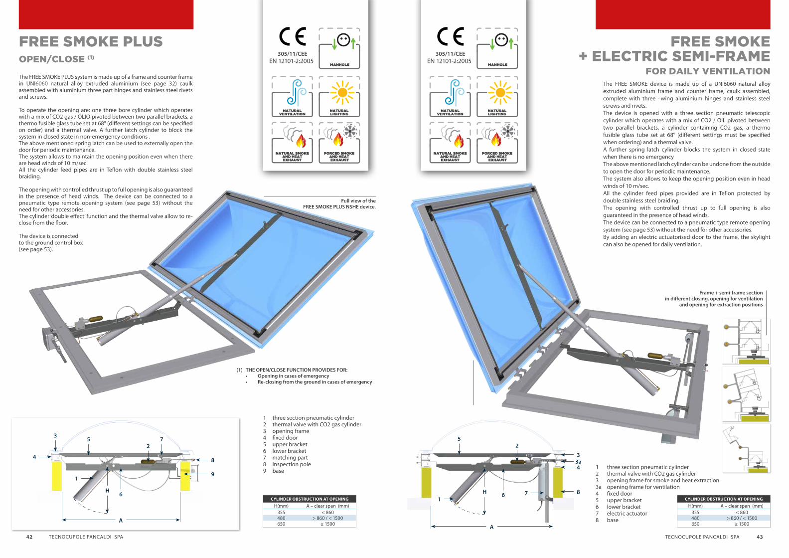
OPEN/CLOSE (1)
FREE SMOKE PLUS
The FREE SMOKE PLUS system is made up of a frame and counter frame in UNI6060 natural alloy extruded aluminium (see page 32) caulk assembled with aluminium three part hinges and stainless steel rivets and screws.
To operate the opening are: one three bore cylinder which operates with a mix of CO2 gas / OLIO pivoted between two parallel brackets, a thermo fusible glass tube set at 68° (different settings can be specified on order) and a thermal valve. A further latch cylinder to block the system in closed state in non-emergency conditions .The above mentioned spring latch can be used to externally open the door for periodic maintenance.The system allows to maintain the opening position even when there are head winds of 10 m/sec. All the cylinder feed pipes are in Teflon with double stainless steel braiding.
The opening with controlled thrust up to full opening is also guaranteed in the presence of head winds. The device can be connected to a pneumatic type remote opening system (see page 53) without the need for other accessories.The cylinder ‘double effect’ function and the thermal valve allow to re-close from the floor.
The device is connected to the ground control box (see page 53).
(1) THE OPEN/CLOSE FUNCTION PROVIDES FOR: • Opening in cases of emergency • Re-closing from the ground in cases of emergency
Full view of the FREE SMOKE PLUS NSHE device.
1 three section pneumatic cylinder2 thermal valve with CO2 gas cylinder3 opening frame4 fixed door5 upper bracket6 lower bracket7 matching part8 inspection pole9 base
CYLINDER OBSTRUCTION AT OPENING
H(mm) A – clear span (mm)355 ≤ 860480 > 860 / < 1500650 ≥ 1500
CYLINDER OBSTRUCTION AT OPENING
H(mm) A – clear span (mm)355 ≤ 860480 > 860 / < 1500650 ≥ 1500
275
3
4 8
91
6
A
H
FOR DAILY VENTILATIONThe FREE SMOKE device is made up of a UNI6060 natural alloy extruded aluminium frame and counter frame, caulk assembled, complete with three –wing aluminium hinges and stainless steel screws and rivets.The device is opened with a three section pneumatic telescopic cylinder which operates with a mix of CO2 / OIL pivoted between two parallel brackets, a cylinder containing CO2 gas, a thermo fusible glass tube set at 68° (different settings must be specified when ordering) and a thermal valve. A further spring latch cylinder blocks the system in closed state when there is no emergencyThe above mentioned latch cylinder can be undone from the outside to open the door for periodic maintenance. The system also allows to keep the opening position even in head winds of 10 m/sec. All the cylinder feed pipes provided are in Teflon protected by double stainless steel braiding.The opening with controlled thrust up to full opening is also guaranteed in the presence of head winds. The device can be connected to a pneumatic type remote opening system (see page 53) without the need for other accessories.By adding an electric actuatorised door to the frame, the skylight can also be opened for daily ventilation.
FREE SMOKE+ ELECTRIC SEMI-FRAME
Frame + semi-frame section in different closing, opening for ventilation
and opening for extraction positions
1 three section pneumatic cylinder2 thermal valve with CO2 gas cylinder3 opening frame for smoke and heat extraction3a opening frame for ventilation4 fixed door5 upper bracket6 lower bracket7 electric actuator8 base
NATURAL SMOKE AND HEAT EXHAUST
NATURAL VENTILATION
MANHOLE
NATURAL LIGHTING
FORCED SMOKE AND HEAT EXHAUST
NATURAL SMOKE AND HEAT EXHAUST
NATURAL VENTILATION
MANHOLE
NATURAL LIGHTING
FORCED SMOKE AND HEAT EXHAUST
305/11/CEEEN 12101-2:2005
305/11/CEEEN 12101-2:2005
25
7
3
4
8
3a
16
A
H

TECNOCUPOLE PANCALDI SPA 45TECNOCUPOLE PANCALDI SPA 44
FREE SMOKE LIGHT natural smoke and heat exhaust devices (NSHE), are one of the essential components in the natural exhaust system (NSHES) .
They are available in single or double flap versions to reach larger areas and can also be accessorized with an electric actuator for room ventilation.
FREE SMOKE devices are designed and produced in compliance with the EN12101-2:2005 standard and CE certified under the provisions of Regulation 305/11 CE, DoP
NA
TU
RA
L S
MO
KE
AN
D H
EA
T
EX
HA
US
T D
EV
ICE
S:
FR
EE
SM
OK
E L
IGH
T
6 7 8 9 10 11 124
2
5
1
3
1
2
3
4
5
6
7
8
9
10
11
12
COMMERCIAL NAME: FREE SMOKE LIGHT / 1 FLAP/ 2 FLAPS
SERIAL NUMBER: #######
FUNCTIONING: automatic / automatic + manual
THERMAL START-UP TEMPERATURE: : 68° C / 93° C / 141° C / 182° C
USEFUL AERODYNAMIC SURFACE varies depending on the size of Aa the device
RELIABILITY : RE 50
OPENING UNDER LOAD: SL 500 (single flap)SL 800 (double flap) LOW 0° C
LOW AMBIENT TEMPERATURE: T 0° C
WIND LOAD WL 1500
HEAT RESISTANCE: B 300
SKYLIGHT REACTION TO FIRE: • B-s1,d0 for polycarbonate• E for Plexiglas
SPOILER RESISTANCE: 10 Hz frequency
SINGLE FLAPThe FREE SMOKE LIGHT/1 system is made up of a frame and counter frame in UNI6060 natural alloy extruded aluminium (see page 32) caulk assembled with aluminium three-wing hinges and stainless steel rivets and screws.To operate the opening are: - a double effect pneumatic cylinder only for opening or open/close is connected to a remote system pivoted between two parallel hinges, - a cylinder containing CO2 gas, - a thermo fusible glass tube set at 68°, - a thermal valve.The closing block on the flap allows to open the door from the outside for periodic maintenance.All the cylinder feed pipes are in Teflon with double stainless steel braiding.
The device can be connected to a pneumatic type remote opening system (see page 53) without the need for other accessories. The device can be used for daily ventilation by installing a 230V, 300 mm stroke electric actuator, optional.
FREE SMOKE LIGHT
View of the FREE SMOKE LIGHT NSHE device and spoiler together (optional)
Detail of the FREE SMOKE LIGHT NSHE
device open for extraction with the position of the
electric actuator for ventilation highlighted
FREE SMOKE LIGHT NSHE DEVICE
when open for extraction detail
5
4
69 1 2 7
3
8
1 double effect pneumatic cylinder2 thermal valve with CO2 gas cylinder3 opening frame for smoke and heat extraction4 fixed door 5 upper bracket6 lower bracket 7 actuator (optional)8 actuator release system (optional)9 base
305/11/CEEEN 12101-2:2005
NATURAL SMOKE AND HEAT EXHAUST
NATURAL VENTILATION
MANHOLE
NATURAL LIGHTING
FORCED SMOKE AND HEAT EXHAUST
305/11/CEEEN 12101-2:2005
(optional)

TECNOCUPOLE PANCALDI SPA 47TECNOCUPOLE PANCALDI SPA46
DOUBLE FLAP
FREE SMOKE LIGHT
The FREE SMOKE LIGHT/1 system is made up of a frame and counter frame in UNI6060 natural alloy extruded aluminium (see page 32) caulk assembled with aluminium three-wing hinges and stainless steel rivets and screws.To operate the opening are:- a double effect pneumatic cylinder only for opening or open/close (when connected to a remote system) pivoted between two parallel hinges, - a cylinder containing CO2 gas, - a thermo fusible glass tube set at 68° (different settings can be specified at time of order),- a thermal valve.
The closing blocks on the flap allow to open the door from the outside for periodic maintenance.All the cylinder feed pipes are in Teflon with double stainless steel braiding.The device can be connected to a pneumatic type remote opening system (see page 53) without the need for other accessories.The device can be used for daily ventilation by installing a 230V, 300 mm stroke electric actuator, optional.
54
27
1 6
3
8
A
1 double effect pneumatic cylinder 2 thermal valve with CO2 gas cylinder 3 opening frame for smoke and heat extraction4 central flap separator5 upper bracket 6 lower bracket7 base 8 spoiler
view from inside the FREE SMOKE LIGHT NSHE
double flap device
Full view of the FREE SMOKE LIGHT NSHE double flap device
305/11/CEEEN 12101-2:2005
FREE SMOKE GLASS is a natural smoke and heat exhaust device NSHE made with extruded aluminium thermal break profiles, painted in standard RAL colours.
The structure for the openable frame must guarantee a frame insert of at least 13mm, with a field of use on slopes with gradients from 7° to 75°. All the seals come in elastomer (EPDM).The profiles shown allow a door opening of approx. 90° with the opening of the hinges on the sloping side inclined “downsteam”.
The opening device is made up of a SINGLE C SECTION/BLOCKS with a span of 740 mm pneumatic cylinder pivoted between two parallel brackets orthogonal to the galvanised steel 40/10 thickness hinge side, thermal valve with spring latch to hold the mobile door, thermo sensitive tube and 60 gram CO2 cylinder.
A seal is inserted to avoid contact between the upper bracket and the glass.The opening position is pneumatically guaranteed even in the presence of head winds.
All the cylinder feed pipes are in Teflon with double stainless steel braiding
The NSHE is re-closed manually from the outside of the frame.
FREE SMOKE GLASS
1 single part pneumatic cylinder2 thermal valve with CO2 gas cylinder 3 frame4 glass buffer
4
3
1
2
NATURAL SMOKE AND HEAT EXHAUST
NATURAL VENTILATION
MANHOLE
NATURAL LIGHTING
FORCED SMOKE AND HEAT EXHAUST
305/11/CEEEN 12101-2:2005
NATURAL SMOKE AND HEAT EXHAUST
NATURAL VENTILATION
MANHOLE
NATURAL LIGHTING
FORCED SMOKE AND HEAT EXHAUST
305/11/CEEEN 12101-2:2005

TECNOCUPOLE PANCALDI SPA 49TECNOCUPOLE PANCALDI SPA48
Blocking element placed flat and made with a 20 mm thick panel in sintered extruded polystyrene covered by two flat surfaces in steel plate.Pre-painted in white/greyThe panel is fixed to the mobile frame by means of an angular profile.
Vertical spoiler, 200 mm in height positioned on 3 sides of the NSHE made in steel plate, connected to the fixed door of the NSHE via suitable spacers complete with stainless steel screws.
The SPOILER can be used with the following products:• FREE SMOKE• FREE SMOKE PLUS,• FREE SMOKE + ELECTRIC SEMI-FRAME• FREE SMOKE LIGHT SINGLE AND DOUBLE FLAP
BLIND PANEL
SPOILERTO INCREASE THE USEFUL AERODYNAMIC SURFACE AA
View of the spoiler in open extraction status
View of the spoiler in closed extraction status
FREE SMOKE V
1 2
3
6 7 8 9 10 11 4
5
1
2
3
4
5
6
7
8
9
10
11
COMMERCIAL NAME: Free smoke V / V PLUS
SERIAL NUMBER #######
FUNCTIONING: automatic / automatic + manual
THERMAL START-UP TEMPERATURE: : 68° C / 93° C / 141° C / 182° C
USEFUL AERODYNAMIC SURFACE Aa
varies depending on the size of Aa the device
RELIABILITY’ : RE 50
OPENING UNDER LOAD: SL 0
LOW AMBIENT TEMPERATURE: T -25° C
WIND LOAD: WL 1500
HEAT RESISTANCE: B 300
SKYLIGHT REACTION TO FIRE B-s1,d0 for polycarbonate
cold drawn profilein external rabbet the open and internal rabbet
thermal cut profile in external rabbet in the open and internal rabbet
FSV09 VERTICAL NATURAL SMOKE ND HEAT EXHAUST DEVICE
Openable external vasistas vertical windows made in cold drawn profile or thermal break extruded aluminium EN AW 6060, silver in colour. The windows come with seals and a honeycomb block which can be altered to customer requirements and suitable fixing.
To open the device are: a multi thrust pneumatic cylinder pivoted between two parallel brackets, a thermo valve with holding spring latch, a cylinder containing CO2 gas and a thermo fusible glass tube set at 68° (different settings must be specified when ordering) .
All the cylinder feeding pipes are in Teflon protected by double stainless steel braiding. There is a flexible cable at the end of the spring latch to manually unhook the door from the outside for periodic NHSE maintenance purposes.
Under extraction conditions, the option to reclose from the floor is provided by the “double effect” function of the cylinder and the thermal valve.
(1) THE OPEN/CLOSE FUNCTION IS INTENDED FOR:• Opening in emergencies• Re-closing from the floor in emergency conditions
FREE SMOKE V PLUSOPEN/CLOSE (1)
1 Thermal valve with CO2 gas cylinder2 opening frame 4 buffer5 upper bracket 6 lower bracket
3
5 21
4
6
View from the exterior
View from the interior
NATURAL SMOKE AND HEAT EXHAUST
NATURAL VENTILATION
MANHOLE
NATURAL LIGHTING
FORCED SMOKE AND HEAT EXHAUST
305/11/CEEEN 12101-2:2005

TECNOCUPOLE PANCALDI SPA 51TECNOCUPOLE PANCALDI SPA50
FRESH AIR EMISSION FROM BELOW
FREE SMOKE AIR
The FREE SMOKE AIR device is made using thermal break aluminium profiles complete with glazing beads and seals with a blind block made of white/grey pre-painted steel sheet with a sandwich insulation panel.
The external vasistas opening comprises a gas spring and two hydraulic springs to control the door in cases of falls up to 90° .
The unhooking device follows an electrical command to “shunt trip” coming from the main system control panel. Re-arming is done manually from a nearby position.
Supply is completed with suitable fixing sets.
The FREE SMOKE AIR device can be accessorized by a door foot support kit in the open position and finishing flashings.
Applicable corrective factor: 0,65According to chart 3 UNI9494-1:2012 Para. 6.7
Exterior view of the FREE SMOKE AIR device (optional grid)
View of FREE SMOKE AIR device closed (external/internal)
NS
HE
SY
ST
EM
CO
NN
EC
TO
N L
INE
S
AN
D C
OM
MA
ND
PA
NE
LS In accordance
with the UNI 9494-1:2012 standard, the devices that make up the natural smoke and heat exhaust system NSHES must be connected and controlled by power supply lines and dedicated command and control panels.
Tecnocupole Pancaldi offers connection lines and pneumatically powered supply boards and electricity line boards.
In the following pages the control and command lines and panels for electrical and pneumatic power and any accessories to be installed on the NSHE will be described.

TECNOCUPOLE PANCALDI SPA 53TECNOCUPOLE PANCALDI SPA52
NSHES CONTROL AND MANAGEMENT UNITControl and management unit for NSHES activation with activation cycle.The unit moves the NSHES components from vigilance state into fire-fighting position via signals coming from the smoke detector system (relay contact) or manual.
The unit is programmed according to the activation sequence provided in the design and can manage output signals both by compartment or common to the whole area.
It is possible to program delayed activation signals (up to a max. of 5 minutes – UNI 9494-1:2012 para.6.9.6.2); during this delay it is possible to abort the fire-fighting action by pressing the reset.
If the alarm coming from the smoke detection system persists then the fire-fighting sequence is once again activated.
Back-up batteries for supporting the signal from the unit and where needed power supply to activate the electromagnetic actuators in the NSHES components are included.
Container size 300x400 mm 225 mm depth.
Protection IP66 – continuous functioning temperature -40°C +80°C (120°C for short periods).
The unit can be programmed from the 4x20 display, multi-task operating system, application software with the option of managing up to 16 digital + 2 analogue inputs, 12 assignable relay outputs for 1-6 zones, memory for up to 50 events..
Front view of the NSHES control unit
Picture of the inside
of the NSHES control unit
The NSHEs must have a suitable input for the pneumatic connection with the boxes on the ground in the thermo system.
This input must allow to open the NSHE without involving the emergency device with which it is fitted comprising a thermo fusible tube and a CO2 cylinder.
In this way it isn’t necessary to replace the above-mentioned components whereas in other cases this would need to be replaced when the electrical grounding emergency system is installed.
The advantages gained by using this system are:• Zero costs for replacing used components,• Possibility of periodically keeping system efficiency under control by the reading on the manometer and the signal control lights on the NITROGEN BOX panel,• High reliability (removes unwanted opening risks in the electrical emergency system).
The connection line can be made up of one or two pipes depending on the NSHE be it only OPEN or OPEN/CLOSE, in this case with the two pipe system it is also possible to command the re-closing of the NSHE from the ground in emergency opening conditions.
Furthermore, the line can be installed either inside or outside the covered rooms.
The connection line between the NSHE and the command panel consists of a backbone with one or two copper 6 mm internal / 8 mm external diameter pipes connected by chrome plated brass fixtures.
The connection between the backbone and NSHEs is made via Teflon pipes with internal diameter of 2 mm / external diameter of 4 mm protected by double stainless steel braiding.
The wall fixing comprises suitable brackets anchored to blocks or screws on the lower surface of the cover.
In the case of external systems, the line described above is inserted inside a PVC pipe.The latter is fixed by means of forks inside an inspection duct anchored to the cover by suitable supports.
PNEUMATIC CONNECTION LINES
Single pipe external connection
line detail
Examples of internal connection lines
Examples of external connection
double pipe external connection line detail
Example of control chart
of an area divided
into 3 zones
LEGEND
LEGEND
PAE_(U/A) (Z/G) N. nElement acronym
PAE_(U/A) (Z/G) N. n
U = Command A= Acquisition
PAE_(U/A) (Z/G) N. n
Z = Zone, G = Common part
PAE_(U/A) (Z/G) N. nZone number/common part
PAE_(U/A) (Z/G) N. nelement no.
Acquisition
Command
Same Commandto following elements

TECNOCUPOLE PANCALDI SPA 55TECNOCUPOLE PANCALDI SPA54
NSHE COMMAND PANEL
This command panel has been designed for installations inside buildings and consists of a box with lock which is 650x405x200 mm in size on the front of which is an alarm button and a LED signal panel.On the upper part of the box are the outputs for the connections to the pneumatic connection lines.
Inside the box are the following:a cylinder of nitrogen with appropriate capacity to open a maximum of 10 NSHEs, a manometer, a pressure regulator and an electro-valve. Furthermore, the BOX is fitted with a back-up battery which must be connected to the network for maintaining the load status (connection to be done by electrical plant engineer).
The command panel can be connected to additional remote alarm buttons (if connected in parallel on the glass breakage button on the front of the box) and for receiving smoke detection alarm signals from an external switchboard.
PNEUMATIC B1/B2 NITROGEN BOX
1
2
3
4
6 5 7 8 11
9
10
1 Disconnected or broken smoke sensor lines2 Switchboard powered by mains at 220V3 Switchboard powered by back-up battery (in the absence of 220V mains)4 Fire/smoke alarm. SHEV in emergency opening5 SHEVS all open signal
6 SHEVS all closed signal7 Back-up battery recharge8 Nitrogen cylinder empty - replace9 Glass breakage button active10 SHEV in opening signal11 Open/close external command Active (only operates on B2)
Front view of the nitrogen
command panel
Panel with
LED signals
Picture of the inside
of the nitrogen
command panel
Emergency button
Front view of CO2 command panel
This command panel designed for installation inside a building comprises a metal container with lock and from one to two carbon dioxide cylinders with enough capacity to activate the connected user stations.
The container size can vary as follows: height from 345 to 700 mm, base from 255 to 560 mm, depth 105 mm
The command panel can receive signals from alarms coming from an external smoke detection switchboard.
NSHE COMMAND PANEL
PNEUMATIC - CO2 BOX
Inside the one CO2 cylinder command panel OPEN only
Inside the two CO2 cylinder command panel
OPEN/CLOSE

TECNOCUPOLE PANCALDI SPA 57TECNOCUPOLE PANCALDI SPA56
NSHE COMMAND PANEL
This command panel designed for installation inside buildings comprises a “box” with lock inside which is a switchboard that supplies electrical power to the actuators installed on the NSHE.
The switchboard comprises a power supply and two back-up batteries. The cabling system must be sized in accordance with the number of actuators and the length of the line.The connection of the command panel to the network line and between the NSHEs and command panel is carried out by an electrical plant engineer.The lines must be made with cables which are fire resistant or suitably protected with non –combustible materials.
The fire resistance of the cables must be in compliance with CEI EN 50200 for 30 minutes and conform to CEI 20-105 (UNI 9494-1:2012 parag. 6.9.4.4.).
Activation takes place by breaking the glass over the button which is supplied separately to the box. The command panel can be interfaced with the smoke detection system.
ELECTRIC SINGLE AREA ERC BOX
Possibility to connect:- max 10 outgoing actuators in parallel - smoke detectors- incoming glass breakage buttons
Front view of the Single Area ERC box
Emergency glass breakage button
WHEN THERE ARE ELECTRICAL CONNECTION LINES
PYROTECHNIC ACTUATOR
ELECTROMAGNETIC ACTUATOR
When there are electrical connection lines between the command panels and the NSHEs, the latter must be accessorized with a local actuator which, on receiving the electrical impulse from the command panel as a result of pushing the button after breaking the glass or from the smoke detector system that triggers the opening of the NSHE causing the thermo fusible glass tube to break.
It is made up of a cylinder inside which is housed a small explosive charge containing a resistance.When the current goes through the actuator it expels a firing pin that causes the thermo fusible tube to break and thus, trigger the opening of the NSHE.
The pyrotechnic actuator must be replaced after use
This comprises a mechanical system driven by an electro magnet which allows the triggering of the NSHE opening cycle by means of breaking the thermo fusible glass tube.The system functions as a “shunt trip”.
After using the electromagnetic actuator does not need replacing but must be re-armed.
NSHE INSTALLATION ACCESSORIES
Pyrotechnic actuator installed on thermal valve
Electromagnetic actuator nstalled on thermal valve
Activated system(firing pin released, broken glass tube)
Intact system
Intact system
Activated system(firing pin released, broken glass tube)

TECNOCUPOLE PANCALDI SPA 59TECNOCUPOLE PANCALDI SPA 58
FR
EE
SM
OK
E C
UR
TA
IN
Smoke barriers are one of the main components of natural and forced smoke and heat exhaust ventilation systems (NSHES and SHEVS).According to the UNI 9494-1:2012 standard, smoke barriers are elements that cordon off the ceilinged area inside a building.
The smoke area must be made in such way as to contain the fumes where the fire has broken out by impeding it to enter surrounding areas.
In this way emergency operations and evacuation of the rooms can take place in conditions of greater safety and visibility and can reduce damage to goods.
The FREE SMOKE CURTAIN barriers are CE Certified under the provisions of Regulation (EU) N.305/2011, and conform to the EN 12101-1:2006 standard.
MOBILE SMOKE BARRIER
FREE SMOKE CURTAIN-M
The FREE SMOKE CURTAIN-M mobile smoke barriers for mounting on the ceiling are made of sheets of cladded fibre glass textile and steel wires. The white sheets are fixed overhead with a galvanised steel shaped upper structure .Mounting can be carried out with or without side rails.
The sheets are wrapped around one or more rollers depending on whether it is a single or multiple configuration. In the latter case the overlay of the textile forms a continuous barrier. The rollers are housed inside a galvanised steel sheet carter.The maximum height of a barrier is 10 metres.
The curtain is moved and managed by a control unit which on receiving an alarm or power cut signal, automatically drops the curtain.Descent is assisted by a 24V tubular motor for rewinding the sheets inserted into the rollers.
FIXED SMOKE BARRIER
FREE SMOKE COURTAIN-F
The FREE SMOKE CURTAIN-M mobile smoke barriers for mounting on the ceiling are made of sheets of cladded fibre glass textile and steel wires. The white sheets are fixed overhead with a galvanised steel shaped upper structure.
A pocket for inserting the tubular curtain tensioning is on the base.
Special steel wire is used for sewing the sheets; the barrier panels are joined by means of galvanised steel plates and suitable fixings. Mounting takes place without side rails.
Single roller barrier detail For widths up to 7 metres
Multiple roller barrier detail For widths greater than 7 metres
Fixed barrier under beam fixing system detail
Fixed barrier fixing system detail in the presence of systems

TECNOCUPOLE PANCALDI SPA 61TECNOCUPOLE PANCALDI SPA 60
The forced smoke and heat ventilation systems (SHEVS) are complementary to natural smoke and heat exhaust ventilation systems (NSHES) and provide an alternative when there are structural restraints.For example: in the case of a multi-storey building or areas affected by the intervention which are in the basement.
Forced exhaust ventilation systems are designed by following principles that are similar to those for natural systems hence, these also demand the installation of several components, some of which are used in the natural system: floor release fresh air devices (see page 50), smoke containment curtains (see pages 58-59).
The basic difference to natural systems is that the evacuation of the fumes from the fire comes from electrically actuatorised fans.Tecnocupole Pancaldi offers Free Smoke Vent devices with CE product certifications in accordance with the UNI EN 12101-3:2004 standard and under the provisions of European Regulation 305/2011.
FO
RC
ED
SM
OK
E A
ND
HE
AT
EX
HA
US
T
SY
ST
EM
S S
HE
VS
Diagram of the FREE SMOKE VENT device activation system.
They are a subset of a larger range of fans certified in compliance with the EN 12101-3: 2004 standard and able to operate at +300°C for 2 hours or +400°C for 2 hours.
The structure is entirely made of steel making the extractor strong and durable, the axial type fan is made in die-cast aluminium. The totally
closed actuators have ball bearings for guaranteeing a long life.
Protection rating IP55.
These products have been designed to be used in buildings such as: shopping malls, stairwells,
closed garages, underground stations.
SMOKE AND HEAT EXTRACTORS
FREE SMOKE VENT
F300 (300° 2H), SHORT BODY (FUNCTIONING ONLY IN EMERGENCIES S2)DESCRIPTION Diameter POLES Nominal Power Actuator size Max capacity Sound pressure level available versions
mm kW m3/h dBA @ 3m max F300 (300° C 2h) F400 (400° C 2h)
FSVENT400/2 400 2 1,32 80 7740-8280 70 sì sìFSVENT450/3 450 2 2,64 90L 12240 77 sì noFSVENT500/4A 500 2 3,45 L90L 15660 74 sì noFSVENT500/4B 500 2 4,6 100L 17820 76 sì noFSVENT400/4 400 4 0,66 80 4680 56 sì sìFSVENT450/4 450 4 0,66 80 6840 61 sì sìFSVENT500/4 500 4 0,66 80 9360 58 sì sìFSVENT560/4 560 4 0,9 80 12600 62 sì sìFSVENT630/4 630 4 1,8 90L 18000 67 no sìFSVENT630/4A 630 4 1,32 90S 17280 65 sì noFSVENT630/4B 630 4 1,8 90L 18000 66 sì noFSVENT710/4A 710 4 2,53 L90L 25200 72 sì sìFSVENT710/4B 710 4 3,6 100L 27000 74 sì sìFSVENT800/4A 800 4 3,6 100L 34560 74 sì sìFSVENT800/4B 800 4 4,8 112M 36540 74 sì sìFSVENT800/4C 800 4 6,6 132M-S 40680-38880 75 sì sìFSVENT900/4A 900 4 6,6 132M-S 46800-47528 77 sì sìFSVENT900/4B 900 4 8,63 132S-M 53640-52200 78 sì sìFSVENT1000/4A 1000 4 8,63 132S-M 63360-61020 81 sì sìFSVENT1000/4B 1000 4 13,2 160M 75960-72540 81 sì sìFSVENT1000/4C 1000 4 18 160L 78120 83 sì sì
F300 (300° 2H), SHORT BODY (DUAL PURPOSE FUNCTIONING S1 ACCORDING TO ERP 2015)DESCRIPTION Diameter POLES Nominal Power Actuator size Max capacity Sound pressure level available versions
mm kW m3/h dBA @ 3m max F300 (300° C 2h) F400 (400° C 2h)
FSVENT500/2 500 2 3,45 L90L 15660 75 sì noFSVENT500/4 500 4 0,66 80 8280-5760 57 sì sìFSVENT560/4 560 4 0,9 80 12600-12780 63 sì sìFSVENT630/4 630 4 1,8 90L 18000 67 no sìFSVENT630/4A 630 4 1,32 90S 17280 65 sì noFSVENT630/4B 630 4 1,8 90L 18000 66 sì noFSVENT710/4A 710 4 2,53-2,64 L90L-100L 24500-25200 72 sì sìFSVENT710/4B 710 4 3,6 100L 27000 74 sì sìFSVENT800/4A 800 4 3,6 100L 34560 74 sì sìFSVENT800/4B 800 4 4,8 112M 36540 74 sì sìFSVENT800/4C 800 4 6,6 132M-S 40680-37440 75 sì sìFSVENT900/4A 900 4 6,6 132M-S 46800-47520 77 sì sìFSVENT900/4B 900 4 8,63 132S-M 53640-50400 78 sì sìFSVENT1000/4A 1000 4 8,63 132S-M 63360-61020 81 sì sìFSVENT1000/4B 1000 4 13,2 160M 75960-72540 81 sì sìFSVENT1000/4C 1000 4 18 160L 78120 83 sì sì
NATURAL SMOKE AND HEAT EXHAUST
NATURAL VENTILATION
MANHOLE
NATURAL LIGHTING
FORCED SMOKE AND HEAT EXHAUST
305/11/CEEEN 12101-3:2004