smart tupperware tm - purdue universityweb.ics.purdue.edu/~rvoyles/pubs/smarttupp.f03.report.pdf ·...
TRANSCRIPT

Smart TupperwareTM
EE 4951W
Final Project Report
Group Members:
Andrew Engebretson
Angela Brockman
Chris Sanny
Hung Le
Mike Wenger
FacultyAdvisor:
Richard Voyles
December 17, 2003

2
Abstract The ultimate goal of Smart Tupperware™ is to create a food storage system using
wireless communication, a display, bio-sensors, and a self-contained power supply that interacts with the user. The benefits of such a product enable the consumer to monitor the activity, inventory, and status of the contents in the Tupperware™. For purposes of this project, there were three major design steps to reach a better prototype of the Smart Tupperware™. The initial design consisted of a new board that replaced the existing board, maintained functionality, and interacted with the current Smart Tupperware™ system in much the same way as the original. This new board is smaller, more efficient, and includes connectors for a display and for a Bluetooth module. The next step in the design process was designing a board that integrated Bluetooth on it for communication. The final step was to create a new application for Smart Tupperware™ that added functionality from the consumer standpoint.
3
Abstract 2 Table of Contents 3 Introduction 4 New PCB Design 5
Circuit size Reduction 5 Enhance Performance 6 Compatibility with Existing and New Tupperware 6 Fixes 6 Bluetooth 6 New Application Possibilities 7 Power Source 8 Final CPU Board Layout 12 Added Functionality 13 Old Application with Improved Technique 15 Aesthetic Design 16 Individual Contributions 16 Conclusion 22 Schedule 23 References 24 Appendix A 26 Appendix B 27 Appendix C 28

4
Introduction As the world becomes more technology driven, computers are being implemented into new applications to make life easier for people. One area that has not yet been explored is the common household Tupperware™ container. The Smart Tupperware™ project aims to automate tasks that are often forgotten by homeowners. Through the use of new technology, such as Bluetooth wireless communication and Biosensors, this new Tupperware™ can collect, analyze, and transmit data relating to its contents; for example, the type of food in the container, the amount of food remaining, and how long the food has been unattended. It would then be able to assist the homeowner by updating shopping lists or by notifying them when something has been sitting for an extended period of time. This will give people the convenience of being able to grab their PDA, go to the store, and have everything they need to purchase show up on a shopping list. The first Smart Tupperware™ team took the idea of an intelligent kitchen and applied it to Tupperware™. The outcome of the first Smart Tupperware™ design was a Tupperware™ container that incorporated sensors, a microcontroller, and a wireless transmitter attached onto a PCB that could examine “the contents of the Tupperware™ autonomously and send the information to a PC where a grocery list could be created”1 for the consumer. The first part of our design was to take the existing board and make several improvements. A significant problem with the current PCB design was the size of the board. In the first design we worked towards eliminating all unnecessary elements, making the layout more efficient, and including an onboard footprint for both a Bluetooth module and a connector for an LCD for.
The second part of the project consisted of implementing Bluetooth directly onto the board. This was an important goal to achieve for the end product since a means of communication is critical for the success of Smart Tupperware™. While the first to portions of the project were being worked on, we also had to focus on the containment of the circuitry for the actual device into something new that is useful, aesthetically pleasing, and feature multiple consumer benefits.
The final goal for the Smart Tupperware ™ project included a significant amount
of research in order to select and add a new application that provided some sort of functionality for the user. Various areas explored for this included implementing a long-lasting, low maintenance power source, adding bio sensors to monitor status of food with respect to spoilage, alert systems for telling the user when the container is occupied and being ignored, and an interactive display (Electronic Ink). All of the mentioned applications were being done in conjunction with an overall aesthetic design that optimizes efficiency, functionality and maintains manufacturability. Future applications that go beyond the scope of this project could possibly include restaurant inventory systems using Bluetooth, or advertisement systems that use Bluetooth, electronic ink, and are sponsored by large corporations such as General Mills.

5
New PCB Design The first step of this project was to create a new board much like the existing one, performing all the same functions, but more efficiently, and with a couple of additional features.
Circuit Size Reduction Last years board measured approximately 75mm x 150mm, ideally, we wanted our board size to be 50x75 mm. In order to achieve this, we needed to make it a multilayer board, removing everything from the first layout that was not necessary or unused. The amplifier circuits were replaced with Instrumentation Amplifiers, (1-1) and the unused amplifiers were removed. In our attempts to clean up the design and appearance of the board, the 3 LEDs that the board currently uses were replaced with one LED that emits 3 different colors.
Figure 1
50mm 10mm
75mm
1-1
1-2
1-3
1-4
1-5
1-6
1-7
1-7

6
Added benefits of the reduced board size, beyond functionality, are that with the shorter connections, resistance in wires and signal degradation is not as big of an issue. This also results from the included two plane layers that serve to bring ground and power connections to the entire circuit through vias (1-2). A view of the power plane is also shown in Figure 1.
Although the board size is 50x75 mm, 10mm had to be added so that the board is now 60x75 mm. This occurred because of a need for an antenna (1-3) for our Bluetooth module. Rather than add an antenna coming off the board, we decided our space would be better used with an onboard antenna that takes up zero vertical space. The updated Layout is shown in Figure 1, with the new schematic shown in Appendix B. Enhance Performance The current Smart Tupperware™ board includes pressure sensors (1-4) and Bluetooth module (1-5). The pressure sensors were tested at various positions. A series of theoretical tests have been conducted to determine the optimal positions for the sensors, however we needed to run additional tests with sensors at these locations to examine the implementation of these sensors. Bluetooth was integrated into the circuit by the first group, but because of limited resources, the integration was done incorrectly. The original design team did some wireless testing with the TR3000, but it was done via connectors. Our design included the wireless onboard (1-6). When redesigning the board we also included an available connection to an LCD for display (1-7). The connectors for the photodiodes and LEDs from last year were used as the connectors used for the LCD. Compatibility with Existing and New Tupperware The existing Smart Tupperware™ serves as a medium for our preliminary testing. Beyond making a replacement board, we also wanted to make our initial board compatible with features that will be implemented on later designs such as the LCD display. In the first design Bluetooth was tested through connectors, we implemented it directly onboard. Having a clean, simple design will make it easier for us and future groups to add new applications. Fixes Although this first design went well, several things had to be changed after the board arrived. Because of a mistake in the preliminary design that was never noticed, several pins were shorted to ground on the TR3000 chip. The mistake was eventually found and fixed on the board. Other than this, a few VCC lines within the Bluetooth module needed to be connected, but this was a simple, quick fix. These mistakes, although frustrating, proved to be great learning experiences on what we should look for, double checking designs, and how to go about fixing a problem when it does occur.
Bluetooth Implementing Bluetooth was one of the main design goals. It is one of the latest advances in wireless communication, and is used to essentially connect all devices

7
together through one interface. It is a low power solution, works virtually anywhere, and it’s compatibility with other devices is unlimited. Bluetooth has an integrated bandwidth solution which uses an unlicensed frequency of approximately 2.4 GHz, and it is cost effective. Interaction between Smart Tupperware™ and all of the other Bluetooth devices in the kitchen requires only one antenna allowing us to avoid implementing excessive antennas and receivers. Obtaining open source code for the Bluetooth module was essential for communication between Bluetooth and the user interface. The Bluetooth open source code opens pathways to enable information transfer to and from other onboard devices. As such, a wireless communication link was set up to a pc based station using a dongle allowing us to transmit data via USB port. Our original idea was to implement the use of a Bluetooth Processor directly to the PCB and add memory modules and other essential components to make the Bluetooth a complete solution. Later, it was discovered that an easier implementation of a module that uses Bluetooth processor in a complete package is available. It maintains all of the key features that we were looking for in wireless communication such as low power consumption and reasonable pricing. The initial design (mentioned above) implemented Bluetooth through a connector – essentially as an add-on to the board. In this design, Bluetooth is implemented directly on the board as it would be in a final product – allowing the device to have an overall more efficient design and fit within size restrictions. Out of several module choices we have decided to use the Infineon ROK 104 001. This module is a compete solution which eliminates the need to create a stack for the Bluetooth. The module includes a baseband processor with 4 Mbit Flash memory, a radio solution, interfacing to an antenna and application, supporting circuitry, and basic Bluetooth software for signaling at HCI level (Host Controller Interface) or ECP level (Embedded Communication Platform). The ECP is the basis of this design choice it essentially eliminates the need for the Stack. A wireless communication link was set up to a pc based station using a dongle allowing us to transmit the data via USB port.
New Application Possibilities The final part of this project was to implement new consumer friendly applications. There were several possibilities for new applications; each of which were geared towards having Smart Tupperware™ evolve into something that is multifunctional and maintenance free. In choosing new applications, consideration fell upon several factors, namely availability of the device in the market place (sensor, power source, etc), pricing, and delivery time. The ultimate goal for Smart Tupperware™ is to integrate state of the art technology, such as Electronic Ink and polymer solar cells, but until these products have had a chance to develop farther, the reality lies more along the lines of LCDs and silicon solar cells.

8
Power Source The future Smart Tupperware™ must have a reasonable serviceable lifetime of
three to five years with no user effort. Although a large battery could satisfy this requirement it would defeat the consumer need for a piece of Smart Tupperware™ that is small and aesthetically pleasing. The power source and storage device need to be invisible and irrelevant to the user so they never have to think about them or do anything with them. In order for the Smart Tupperware™ to operate for long time and still keep it a consumer acceptable product, two important goals had to be met in the design process: 1) the power consumption by the circuit needed to be minimized and 2) the energy storage device had to be small and recharged by extracting energy from its surroundings.
Initially, thought and research was put towards methods for reducing the power
consumption of the Smart Tupperware™. The main energy consumer in the Tupperware™ that had to be addressed was the microcontroller. The Atmega128L was the microcontroller used by the previous team, and it is a power hungry chip, drawing 5mA of current in normal operation with 3V as its input voltage. We decided that we could use a Texas Instrument MSP430x41x microcontroller because of its extremely low power demands (needing only 240uA in normal operation with 3V input) and similar functional capabilities as the Atmega128L. Other features of the Smart Tupperware™ that needed to be considered for power were a display, a Bluetooth module, and a biosensor.
In order for the energy storage device in the Smart Tupperware™ to last three to
five years, and still be small and acceptable for common household use, the energy used by the Tupperware™ needs to be replenished frequently. Therefore, the energy storage device needed to be sized so that it could supply enough energy to operate the Smart Tupperware™ until the energy could be replenished. In order to supply an ample safety margin, it was decided that the storage device should be capable of supplying enough energy to operate the Tupperware™ for one day. Table 1 shows a breakdown of the current (Amps) used in each operation mode of the Tupperware™ and the total energy needed on a daily basis for the Tupperware™ to operate. Each duty cycle mode describes the device in the Tupperware™ that is operating. After each device has done its job it is turned off and the Tupperware™ moves on to the next operate the next device. For example, once the Bluetooth has received and sent its information it is turned off and the Biosensor is read, then that is turned off and the next mode turns on.
Duty Cycle Modes Current Draw
(mA) Operation Time (sec) Cycles/Day uAhr/day
1. Quiescent (Off) Mode 0.0001 continuous 2.1 2. Micro and Bluetooth waiting 0.4 20 1 2.22 3. Micro and Bluetooth 20 1 1 5.56 4. Micro and Biosensor 0.287 2 10 1.59 5. Micro and E-Ink 0.24 20 10 13.33 6. Micro stabalizing/pwr down 0.24 1 10 0.67 Total Daily Power Requirement 25.47 Total Daily Energy Requirement (uWhr) 76.42
Table 1

9
Several storage device options were researched to find the best solution for Smart
Tupperware™. Capacitors and rechargeable batteries were the two primary energy storage devices explored. Energy stored in a capacitor is determined by Eq. 1, therefore in order to store 76uWhr of energy at a constant voltage, capacitors with a high energy density and a large capacitance (approximately 0.2F) would be needed to operate the Tupperware™.
2
21
CVW = Eq. 1
The capacitor also had to supply sufficient current to power the Tupperware™ for an extended period of time rather than with short, large bursts of current. Most capacitors are designed to supply very short, large bursts of currents, but cannot maintain the current level for a long period of time. Panasonic SD series Gold Capacitors seemed to be the best option for Smart Tupperware™ since the capacitors are small, have a low working voltage (5.5V), a large capacitance (0.022-0.33F), and would be able to store enough energy to operate the circuit for a day. After testing the capacitor, I found that when it was charged to 3V it could supply a maximum of 23.1mA for a fraction of a second through a ten ohm resistor. After 30 seconds the current had dropped to 8.2mA. The capacitor would be a feasible device to use in the Smart Tupperware™ because it is small and could supply the 20mA of current needed to operate the Bluetooth. However, an even better rechargeable battery solution was found. LiTE*STAR batteries are made by Infinite Power Solutions (IPS)7. These batteries are solid state devices, that are similar to capacitors, having two layers separated by an insulator, but they have higher charge efficiency and can support larger loads for a longer period of time. LiTE*STAR batteries are much smaller than the capacitors and can be easily integrated onto the board. A 0.5cm2 LiTE*STAR battery is large enough to store the 76uWhr of energy needed to operate the Smart Tupperware™ for a single day.
Once the battery was selected, the design challenge was to find a way to recharge
it so that the energy lost during the operation of the Smart Tupperware™ could be replenished in a manner that did not require any user interface. The best way to do this would be by extracting energy from the environment. Three charging devices were considered; piezoelectric, inductive, and solar charging. Piezoelectric charging did not turn out to be a very good solution because the piezoelectric device needs to be in an environment where there is a lot of vibration if it is to produce any energy. The kitchen would not satisfy the environmental conditions necessary for piezoelectric charging.
Inductive charging seemed like the most promising device because it could supply
the most energy. Testing was done with inductor coils and it was found, by extrapolating the data in Table 2 and the graph (Figure 2), that if the coil were plugged into the wall, it would supply 275mW of power to the energy storage device. The inductive charging method could easily recharge the battery in seconds. The problem with inductive charging is that the consumer would have to buy an inductor pad with the Tupperware™, and the Tupperware™ would have to be set on the pad in order to recharge it. This extra work would cause enough inconvenience to deter most customers from purchasing the product.

10
Frequency Vin (V) Iout (mA) 60Hz 0.72 0.026 60Hz 1 0.042 60Hz 1.2 0.052 60Hz 1.52 0.071 60Hz 1.9 0.093 60Hz 2 0.098 60Hz 2.53 0.128 60Hz 2.74 0.142 60Hz 2.95 0.152
Turns ratio: N1:N2 = 80:40
Slope = 0.044mA/volt 60Hz at 120V, Output Current = 5.25mA Ouput Voltage = 5.25mA*10 = 52.5mV Ouput Power = 52.5mV*5.25mA = 275mW
Table 2
Induced Inductance (60Hz)
0
0.02
0.04
0.06
0.08
0.1
0.12
0.14
0.16
0 1 2 3 4
Primary Voltage (V)
Out
put C
urre
nt (
mA
)
Series1
Figure 2
The solar cell was the third charging device that was researched. Solar cells
would be the most user friendly method of recharging, because they could be incorporated onto the Tupperware™ in such a way that the user would not even know they are there. A new area of solar being researched is the polymer based solar devices1. The polymer solar cell chemical mixture could simply replace the polymer Tupperware™ mixture during manufacturing and each piece of Tupperware™ would come out of the assembly line as a solar cell. Manufacturing would be cheap because these cells can be produced at room temperature, unlike the current silicon solar cells which need to be made in special conditions. The cell would also have the largest surface area possible to extract energy from its surrounding light since the whole surface of the Tupperware™ would be a cell. Currently, polymer based solar cells only have efficiencies of about 2%. The University of California Berkeley and Lawrence Berkeley National Laboratory have been leading much of the research in polymer based solar cells. Several of their scientists are very optimistic about these solar cells reaching efficiencies of 10%2.

11
Even if the polymer solar cells do reach efficiencies of 10%, the question still
remained as to whether or not sufficient energy can be extracted from the environment around the Smart Tupperware™ to power the Tupperware™. The light source for the solar cells will come primarily from the refrigerator light or kitchen lights. Testing was done with a silicon solar cell in the refrigerator and in an area that simulated a kitchen counter to confirm that enough energy could actually be supplied to recharge the battery. The refrigerator had a single 40 Watt bulb in it and the shelves were approximately 75% covered with food items which would restrict the light reaching the cell. The cell was placed on all the shelves and the power output measurements were taken. Since kitchen lighting varies between homes, the test was done in an office area with four 30 Watt fluorescent bulbs seven feet above the table. The solar cell was placed in the best case lighting and worst case lighting in the room. The assumption was made that the silicon solar cell is approximately 17% efficient4, so 60% of the output power of the silicon solar cell was taken to find the output power of the polymer solar cell (since the polymer solar cells would only be 10% efficient). Table 3 shows the time it would take for the solar cells to produce enough energy to operate the Tupperware™ for one full day if it is sitting in the specified locations. Even if the Tupperware is sitting in a dark location in the kitchen it would only take 3.4 minutes to supply enough energy to operate it for a full day which is very feasible.
Location of
Tupperware™ Time to produce energy to operate the Smart
Tupperware™ for one full day (sec) Kitchen Counter 44 Kitchen Counter/Dark 204 Fridge (top shelf) 28 Fridge (second shelf) 65 Fridge (bottom shelf) 232 Fridge (worst case) 1891
Table 3
A more important situation that was studied was the energy used versus the energy produced during a single operation of the Smart Tupperware™. Tables 4 and 5 show the difference between the energy produced and the energy used when the Tupperware™ is in use. The last row in Table 4 shows that the solar cells on the Tupperware™ produce 24.68uWhr when it is sitting on the kitchen table and operational. If the Tupperware™ were to be in operating in the bottom shelf of the fridge it would again produce more energy than it would consume, as shown in the last row of Table 5. The worst case scenario was also taken: when the Tupperware™ is sitting in a dark corner in the kitchen and it has to operate. In this scenario the Tupperware™ consumes 1.81uWhr more than it produces. The same data was calculated assuming efficiencies of the polymer based solar cells would only reach 6% and it was found that the Tupperware™ would again consume 9.43uWhr more energy that it would produce.

12
Location of Tupperware™: On kitchen counter Event Energy Produced – Energy Used
Duty Cycle Mode 1 and 2 15.52 Duty Cycle Mode 3 -15.56 Duty Cycle Mode 4 1.74 Duty Cycle Mode 5 18.19 Duty Cycle Mode 6 0.91 In Fridge Until next use (bottom shelf) 3.88 Total Energy Produced (uWhr) 24.68
Table 4
Location of Tupperware™: Bottom shelf in fridge Event Energy Produced – Energy Used
Duty Cycle Mode 2 -0.01 Duty Cycle Mode 4 0.18 Duty Cycle Mode 5 2.57 Duty Cycle Mode 6 0.13 In Fridge Until next use (bottom shelf) -0.87 Total Energy Produced (uWhr) 2
Table 5 Although the worst case situations showed that the Tupperware™ would consume more energy than it produced the normal conditions in Tables 4 and 5 indicate that the possibilities with polymer solar cells as the charging source for the Smart Tupperware™ are very promising. More research will have to be conducted once polymer solar cells have had a chance to develop and improve their efficiencies. So far the feasibility studies done show that polymer solar cells are a viable solution. Final CPU Board Layout
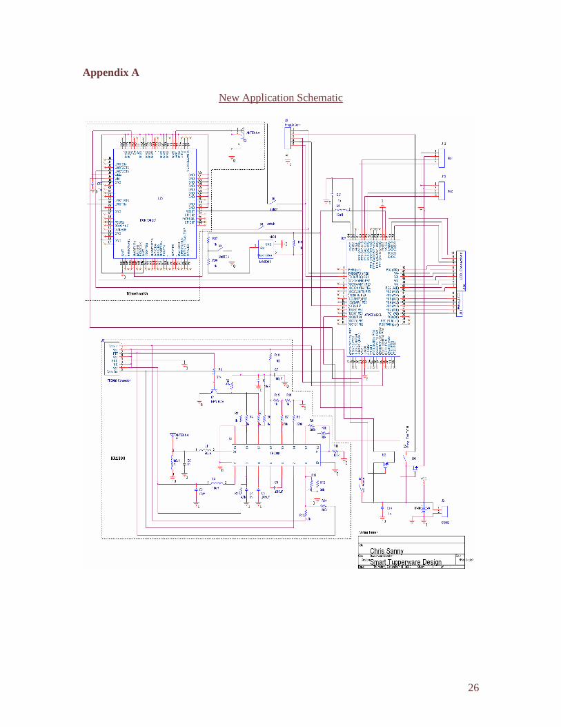
The final design of Smart Tupperware ™ has all of the sensors and circuitry needed for our application contained within one central unit (see Appendix C). In order to do this, Bluetooth was implemented directly onto the main board as with our previous redesign (1-5), and enhancements were made to accommodate the new application. See Figure 3 for the new design.
The first step in creating this design was to remove all of the unnecessary components and connectors that we would not be using. This included all of the connectors for sensors from the previous design, as well as removing the pressure sensor circuitry from the board. All of the connectors we would be using were then added to the board, including the LCD display (3-1) and the two Biosensors (3-2). The backup wireless system (3-3) was also updated from our last design (where some mistakes had been found) to more closely match the datasheets we had for this circuitry. On the Bluetooth module, besides fixing the VCC lines from the last design, vias were placed underneath pins that might need to be used later (3-4), so that they can be easily accessed.

13
Finally, vias were used much more liberally throughout the design in order to better eliminate long traces that might give sensitive components problems with noise from the power and ground lines. The final schematic for this layout is shown in Appendix A.
Added Functionality
Some ideas for added functionality were to include applications that inform the user about the contents of the container. A program for updating a shopping list when food supply within the container is low was created with the initial Smart Tupperware ™ prototype. Other ideas included an alert that is activated when the container remains inactive for a certain period of time, or an alert that is activated when the contents begin to spoil. Spoilage detection was designed with the use of biosensors, and based on preliminary research this was a very feasible application.
Spoilage in food can be determined by observing the level of Oxygen, Nitrogen,
Carbon dioxide and the water vapor in the food container. The combination of these measurements can be very cumbersome and inefficient unless we chose one common element to measure. Oxygen does not seem to have a fast reaction rate toward non-fatty
Figure 3
3-1
3-2
3-3
3-4

14
food such as cereals or sweet candies. Therefore to measure the level of Oxygen in a container of cereal would require a very long time to see any measurable change. Nitrogen measurements are subject to inaccuracy because some foods already contain high amounts of Nitrogen (such as vegetables) and they can alter the results when trying to measure Nitrogen levels. Carbon Dioxide could also be used to measure a presence of bacteria, but since some bacteria do not emit carbon dioxide as waste, it was not our best option.
Finally we came to the idea of measuring the amount of vapor present within a
container. Microorganisms require water for growth and reproduction. Water acts as an essential solvent that is needed for most biochemical reactions in living organisms. The lack of water prevents the microorganisms from growing. In theory the environment that bacteria grows in changes from its initial humid state to a humidity level that would be ideal for bacteria to continue growing. Thus by measuring this change in humidity in the container, we would be able to deduce the activity of bacteria inside the container. However this idea was not able to carry through due to the lack of evident and studies to show the correlation between the changes in humidity and the activity of bacteria. Therefore, we were not able to carry through the idea of detecting spoilage in food as an application.
Nevertheless, even though our initial idea of detecting spoilage in food failed, we
were able to fall back on the idea that certain food has certain Relative Humidity (RH) levels that would keep the food fresh and preserve its lifetime12. This Relative Humidity is related to the ratio of the vapor pressure on top of an environment to the vapor pressure on top of pure water. That is, if the water vapor pressure on top of food is designated as Pf, and the water vapor pressure above pure water is designated as Pw, then (Pf / Pw)*100 gives us a ratio known as the Relative Humidity (RH)13. This monitoring system can be a preventative way of taking care of the food by not letting it spoil.
The idea that certain food requires certain RH values to remain fresh and long
lasting is used by refrigerator Manufacture Companies to keep meat, dairy products, fruit and vegetable fresh in the refrigerator14. There are also studies done to indicate that certain foods fall under specific range of RH values. Thus this idea of adjusting the humidity inside the container to keep the food at its optimal environment is no different than a refrigerator having opening slides for different food compartments.
In the future, our design of the Tupperware™ could have an indicator light on it
to indicate if the slide on the cap needs to open more or close more to preserve the optimal environment for the food. This is accomplished by having two humidity sensors on the Tupperware, one on the outside to sense the water vapor pressure in the environment and the other humidity sensor inside the container to sense the humidity of the air above the food. This way if the food inside the container requires more humid air and the atmospheric humidity is high then the indicator on the Tupperware™ will tell the user to open the slide to let more humid air in. Otherwise if the atmospheric air is dryer than the air inside the container then the indicator on the Tupperware™ will notify the

15
user to close the slide to prevent dry air from entering and keep the moist air inside the container. Old Application with improved technique
The previous group used the volume and mass from the sensors to determine the density of the substance inside the container and the color spectrum to determine the type of cereal inside the container. They used the IR sensors on the side of the container to determine the volume occupied in the container and the strain gauge on the base of the container to determine the mass in the container. However from analyzing the data collected from the previous group on the color specification of different food, we decided that color alone was good enough to identify the type of cereal in the container (Figure 4). We decided to take out the side IR sensors that were there to determine the occupancy volume in the container. By removing the IR LEDs on the side we have reduce the complication of running wires around the container. This gives our new design of the Tupperware a cleaner look and less data to deal with. Thus now we only have the color specification data (no density information) to determine the type of food inside the container.
Figure 4
Green vs. Blue
0.00
0.50
1.00
1.50
2.00
2.50
0.00 0.20 0.40 0.60 0.80 1.00 1.20 1.40 1.60 1.80 2.00
Green
Blu
e
CPOP
CFLAKE
FLOOP
CPUFF
RBRAN
Red vs. Green
0.00
0.20
0.40
0.60
0.80
1.00
1.20
1.40
1.60
1.80
2.00
0.00 0.50 1.00 1.50 2.00 2.50
Red
Gre
en
CPOP
CFLAKE
FLOOP
CPUFF
RBRAN

16
Aesthetic Design The final Smart Tupperware ™ product needs to be something functional as well
as aesthetically pleasing. Basic Tupperware™ sells a variety of products – from containers geared towards specific foods to popular merchandise designs. Smart Tupperware™ takes the best features of Tupperware™ further. The final design consists of a universal module that snaps into various sizes of Tupperware™ (Appendix C). It is something that was closely designed with Tupperware™ to maintain manufacturability. A central containment portion for circuitry and sensors has a number of benefits, most of which can be seen directly by the consumer. The universal snap-in module contains the basic circuitry (including the Bluetooth wireless device) and sensors for detecting the contents, as well as the display to provide useful information to the user. This piece fits various sizes of Tupperware™ making it possible for the attachable containment portion to be heat and water resistant (within the normal uses of Tupperware™).
Not only does the design system of a universal snap-in module serve purposes of
convenience, it is also more cost effective. The consumer can buy and replace the basic container pieces while having fewer of the modules. Current variations of Tupperware™ are sold in sets, depending on occasion or use. With this design, Smart Tupperware™ is a logical addition to the Tupperware™ family. It can be sold as a set – multiple sizes and shapes for various uses and fewer of the cost concentrated modules.
Individual Contributions In a project of such ample proportions it is difficult to break tasks down to individual contributions. Much of the time put into this project was as a group, or upon group approval. All decisions, down to the most seemingly insignificant, were made as a group. Taking all points of view into consideration when making each decision caused us to scrap many ideas that at one point seemed to be evident, and forced us to constantly rethink each part of this project. This is part of the design process, however, and eventually it led us to the best-suited result. To improve future designing processes, included are not only the decisions that are reflected in our final design, but also possibilities we researched into, why they didn’t work, and future facets that can be easily implemented based on our design. Chris Sanny
One of the primary things I worked on at the beginning of the semester was brainstorming and researching ideas for what our new design was going to accomplish. Most of my research was spent looking into LCD’s, both for our project, and for future designs. As our design became more solidified, I took the task of creating the circuit board that would be designed from last year’s project.
The tasks in redesigning the board included: Removing unneeded circuitry and
replacing it with what we would be using, creating and maintaining the board design as new ideas and corrections were made, implementing new efficiency ideas relating to

17
power and ground connections, and using connectors to interface to all of the off board components.
A large portion of my time in redesigning the board was in creating footprints for
components that were not included in the OrCad Layout Libraries by setting down pins and part outlines according to their specifications. Once this task was complete, I was able to spend most of my time organizing the circuitry so that it made sense, as well as making connections across the board as short as possible.
Once this board was ordered, I soldered on a good portion of the components,
with Hung helping on several areas as well. A lot of testing was done by other group members for their respective sections, but I worked on the RF circuit (the TR3000 chip) to try and get it functioning properly. Although I was able to fix some mistakes I had made in the design and was able to get it to transmit, the data it was sending remained unrecognizable. To compensate, I made the design for our application, mentioned below, as error-proof as possible.
From this point, I helped out making connectors for the board to all of the off
board components, and in retrieving datasheets for the LCD so that Mike and Angela could start testing its operation. I was also able to help out in showing the operation of the LCD, and in giving information about the data it would need to receive to its respective pins.
Once the group had a good idea as to what the new application would be, I was
able to begin working on the new board design. I started with the previous design I made, and removed components we would no longer need. I then added connections to the LCD and Biosensors, as well as updated the layout for the RF wireless circuit that we had trouble with. Basically, I made the RF exactly resemble the original datasheet that it was designed after, whereas before I had removed unneeded components and moved things around to save more space.
Learning from past mistakes and advice from Professor Voyles, I added vias to
pins that we were not using underneath the Bluetooth module so that they could be accessed at a later date. I also made the design more efficient by utilizing the power plane to bring power connections to each part of the circuit, thereby eliminating long traces that would cause noise and resistance in the lines. In this manner, vias could be used to bring power and ground directly to sensitive components, rather than traveling a long trace.
By labeling components and sections of circuitry, as well as by keeping the layout
organized, I hope future groups will have an easier time designing their board from mine, giving them time to focus on other aspects of the project as well.
Although this part of the project was very challenging, it brought many learning
experiences, both from mistakes I made as well as from successes. The knowledge I gained will be invaluable in future projects and jobs.

18
Angela Brockman From my perspective, the Smart Tupperware™ project has been as close as I
could imagine to an actual product development project we might encounter in the ‘real world’. Every plan we had for this project was put through scrutinizing review by not only all of the group members, but also by Professor Voyles. I took responsibility for the design of the Smart Tupperware™ container and from that aspect; it was no different than any other part of our project. The container itself carries a large weight in determining whether or not this product will be marketable and accepted by consumers. When making designs I kept in mind the fact that this product will be altered many more times before it reaches its final stage. This will mostly be because of the technology that will be implemented in Smart Tupperware™.
My designs began with simple sketches and eventually evolved into three
dimensional drawings for submittal to Tupperware™, that they may produce sample containers for us to work with. The first design, pictured above, was designed for production and testing. It has locations for all of the devices that have been implemented up to this point. One of my key design points is to make the Tupperware™ so it has a removable, universal module. I did this with the intention that Smart Tupperware™ can be sold in sets or as individually. With this design, different sizes of Tupperware™ can easily be used on the same module that contains the circuitry housing. The main benefit of this design from the consumer standpoint is that you can use the part of the Tupperware™ that stores food on its own, and more importantly, it is washable.
All of the three dimensional drawings were done using Solid Works. I chose this
application for doing my designs because it seems more intuitive than similar applications like ProEngineering, and the tutorial that goes along with Solid Works is informative and easy to understand. All of the Tupperware™ parts were made separately with specific dimensions and later assembled to produce the entire product (as pictured above). Solid Works files can be saved as specific Solid Works parts, drawings used in other modeling tools such as ProE, and more importantly, as drawings that can be recognized by the software used at Tupperware™. I feel that doing this part of the project was not only beneficial to the project itself, but also to me because it gave me a chance to learn a professional three dimensional modeling tool.
I was also responsible for many of the things that determine our appearance as a
group. By this, I refer to things such as the presentations and reports. This project has

19
many aspects beyond the basic designing and implementation. All of the designs, ideas and research make up the final product, but finding a way to include all of these things and keep the goal of our project clear was a task of its own. For the reports and proposals I’ve done a majority of the writing for the introductions, conclusions, and abstracts, as well as going over the final papers and coordinating everything once every one contributed their part. More recently I did much of the work with reorganizing our presentation so in the end we were able to present Smart Tupperware™ as a project rather than the contributions from five individuals towards an idea of a product. Our presentation improved greatly, and we were able to deliver clear points as to what we did, and what we had in mind for this project.
Finally, I’ve assisted Mike with coding for the microprocessor, Bluetooth and
LCD. He most certainly has been responsible for this part of the project, but because we didn’t get everything we needed for Bluetooth until very (very) recently, I jumped in, in an effort to complete everything we had originally intended. I have an extensive background in programming C for various devices and having two people programming is always better than one. Michael Wenger
At the beginning of the semester our design criteria was to implement the Bluetooth into our Smart Tupperware design. Thru extensive research on the methods for implementing the stack for the Bluetooth I found a solution that was a little simpler. I found that the need for a module was much more applicable, based on time and power constraints. If we where to implement the Bluetooth chip as a whole we would require radio solutions, memory, stack solutions, and other various configurations or devices to meet our criteria. I had several modules or other RF devices that use the Bluetooth chip. However the one I chose had to be based on price, accessibility, size, cost, and power constraints, the one that I felt met all these constraints is the Infineon ROK 107001.
The next device that was also being taken into consideration was the microcontroller; another part of our design specifications was to have a low power profile to meet the wireless needs, and to make it in a compact design. By choosing the lowest power needy devices we can make changes to the Smart Tupperware road map. For future implementation, I would choose one of the Texas Instruments (TI) msp430 family microcontrollers. In comparison to the Atmel the TI consumes a marginal amount of power; in active mode the Atmel consumes 5mA and 2mA in idle mode, the MSP430x41x which has similar functionality consumes only 200µΑ in active mode and 7µΑ in standby. The TI also has an off mode that keeps a clock running and consumes 1µΑ. As this project progresses Smart Tupperware will be considering this into the implementation. However based on time limitations we continued the use of our current Atmel Atmega128L processor.
A large portion of our time went into researching devices that we can implement our design. Once the devices have been chosen we needed to implement them into a circuit. Deciphering the Data Sheets I was able to communicate with Chris, and decide which pins go where on the PCB. Basically we are trying to make a connection to

20
specific ports of the Bluetooth module and to specific ports on the Atmel microcontroller. However I ran into some problems as we where running out of data ports left available for communication to the other peripherals onboard, which was solved when Chris made the decision to run the devices in parallel. Considering the power constraints this could have been a problem, but I was able to figure a solution in the programming part.
Programming is an ongoing process, trying to find every possible bug or error so we can get the Smart Tupperware to do what we want it to. One of the specifications that I took consideration in choosing the Bluetooth module was the ECP (Embedded Communications platform) also known as HCI (Host Controller Interface. By having this embedded I eliminated the need to create a stack for the Bluetooth and thus communication to the Atmel would be a lot simpler. AVR programming packages for the Bluetooth module were obtained from Infineon, this was the source files that allows us to communicate to the Bluetooth. With out these programming the Atmel to communicate to the Bluetooth module would be impossible of course with out creating my own stack for the Bluetooth module. Prior to programming for the Bluetooth was trying to figure out how the Atmel communicates to the other devices. I used last semester’s project to work with, breaking down all the components that they got down and seeing how each portion communicates. Once that was done I was able to start programming for some of the newer peripherals that we are including. Hung Le
One of my main assignment consisted of researching various devices to sense spoilage including Ammonium sensing, Carbon Dioxide sensing, Oxygen sensing, Nitrate sensing, and Humidity sensing. Once I determined that we should use the humidity sensors to detect spoilage and/or to help keep food at its optimal state, much research had to go into bacteria and its optimal living environment. If we were going to make a new application based on food and spoilage, we needed good, solid data on what conditions would be the best to keep food tasting fresh as long as possible.
The research started out by coming up with a theory that can determine spoilage
in food. The theory is that the change in humidity in a closed container is related to the activity of bacteria growth. This theory is supported by several facts. One of the facts is that living microorganism in food breakdown the food10. This event releases the trapped water vapor in the food, thus the release of extra water vapor will increase the humidity in the container. The second fact is that most microorganism like to live in humid places9, therefore living bacteria tends to create the environment to better suit their living. Thus bacteria will tend to make an environment more humid to better suit its needs. From the two facts above I was able to conclude a theory that an increase in humidity can indicate the presence of microorganism activity. I then searched online and researched papers for data to support this theory. However there wasn’t any valid data from any source. I ended up doing some measurements at home with a home analog humidity sensor (+-5% humidity errors). However, no big changes were observed with that humidity sensor. Nevertheless I did notice more water condensation was observed on the
21
container where spoiling is present. Beside this small evident and no other solid evidence I chose not to continue with the ideal of identifying spoilage in food.
However, because I chose to sense humidity, I was able to fall back on the idea
that different kinds of food have different humidity level to store in that keeps the food fresher. With that idea, I gathered information on Relative Humidity of different kinds of food. The data to support this idea came up positive. So I decided to go ahead with the idea of the possibilities for adjusting the food environment based on the current humidity level and the optimal humidity level for the stored food.
Lastly, I also did research into improving the design from last year. I needed to
understand what was done with last year’s model, especially regarding the strain gauges, where the best place to use them, and finding replacements for the existing RGB LEDs along with removing the side IR LEDs that is not needed for the application. I also assisted with soldering the board, assisting in setting up the microcontroller programmer, and various testing. Andy Engebretson
My main assignment was as the project leader. This included maintaining the development and overview of the project, keeping tabs on the progress of individuals in order to stay on schedule, keeping an agenda for the meetings, and keeping track of when the different parts of the project were due. For this project, much of our progress was dependent on outside sources, so the schedule was constantly being modified. I had to coordinate how people could use their time and assist in other areas of the project when an outside source caused a delay. Because I had to keep an overview of every element of the project I became involved practically with each individual’s part of their project. I helped a lot with the redesign of the first board with the implementation of the instrumentation amplifiers on the board, finding and ordering most of the parts for the board, testing the separate (not the onboard) communication device (DR1300-DK) on the old and new board, soldering on the Bluetooth module, which consisted of a board grid array (BGA), and the first TR3000, which was like flip-chip. Both components required putting down balls of solder on the pads lining the chip up with the pads and heating the bottom of the board until the solder melted. This task was a learning experience. I also assisting with editing the papers as a whole and making sure everything that was required was included in the final product. I took on the task of getting everyone’s parts of the final paper together, editing it and turning it in, since Angela was helping with the code.
The other task that I took up was coming up with a power source that would fit our new Smart Tupperware ™ application. I needed to come up with a new idea for the power scheme that would deliver enough power to the Smart Tupperware™ electronics for the necessary amount of time. This required figuring out how the circuit was going to use the power and how much current the source would have to supply and for how long. I then had to research energy storage options and order parts and samples to use for testing and implementation. The LiTE*STAR battery did not come in, so I did some tests with the capacitor. I also had to work with Mike to come up with a structure (that will eventually have to be implemented with code) that would help meet the power
22
budget by switching off devices when they were not being used. A major part of the power scheme was the power source. I wanted to have a power source that would extract energy from the environment. I researched several different options. Polymer solar cells seemed to be the best option, so I did some feasibility calculations to see if they really would be able to supply sufficient energy for the Smart Tupperware™. I ordered solar cells about half way through the semester, but the company never sent them, so I had to resort to using a single cell from a calculator to test the power output I could receive from the Tupperware™ if it were to be a complete solar cell. I performed tests in a fridge with a 40Watt bulb in it, and also in an office setting where the lighting simulated kitchen lighting. Once I had collected the data from the cells I created several excel spread sheets that calculated the power output, time to charge the battery based on the power output, and whether energy was consumed or produced each time the Smart Tupperware™ performed an operation.
I also built several little inductor pads with transformer wire and tested them to
see how much power I could get from them to charge the Tupperware™. I created spread sheets and graphs from the data. I experimented with different frequencies and different turns ratios to see how I could get the most power out. All the information was arranged on a spreadsheet.
Conclusion As Smart Tupperware evolves, it is becoming a more feasible product for the intelligent kitchen. The technology exists to create a product that determines what the contents are, monitor the status of them and provide useful information to the user (both from the users’ standpoint as well as possible vendors). The challenge arises with the task of incorporating all the technology into a small, wireless, no-maintenance system that any person can use and afford.
The evolution of this project progressed with the completion of modifying the existing circuit to be smaller and more efficient, and included connectors for a display and Bluetooth. The second substantial step was in designing a circuit with Bluetooth implemented directly into it. We had to the redesigned board to implement the new application of sending information about the contents of the Tupperware™, the date it was put in and the expiration date via Bluetooth to the board, and displaying it on the LCD. This new application is directed towards benefiting the consumer by means of increase in functionality of the Smart Tupperware™.

23
Schedule:
9/9
10/2
10/7
10/28
Final Project Presentations
Begin Project/Organize
Bluetooth research
Bluetooth implementation
Bluetooth Coding
Test/Review existing circuitry
Reduce circuit size, complete layout
Research Power sources
9/29
Order Power Source
Implement Power Source
Research Displays
Choose Display 9/29
Order Display/Implement
Design container
Final containment design, order materials
Ordered Biosensor
8/10 8/17 8/24 8/31 9/7 9/14 9/21 9/28 10/5 10/12 10/19 10/26 11/2 11/9 11/16 11/23 11/30 12/7September October November December

24
References:
1. Yarris, Lynn. “New Hybrid Solar Cells Combine Nanotech With Plastics”. Research
News, Berkeley, CA. March 29, 2002 2. Sanders, Bob. “Cheap, plastic solar cells may be on the horizon, thanks to new
technology developed by UC Berkeley, LBNL chemists”, Campus News Press Release, UC, Berkeley. March 28, 2002
3. “Plastic solar cells are on the horizon”, Chemical Science and Engineering
Newsletter. Volume 10, Issue 3. UC Berkeley. May 2002 4. NREL web site: http://www.nrel.gov/clean_energy/photovoltaic.html 5. Shaheen, Sean E., Brabec, Christoph J. and Sariciftci, N. Serdar. “Applied Physics
Letters”, Vol. 78, No. 6, pp. 841–843, 5 February 2001 6. Infinite Power Solution’s web site: http://www.infinitepowersolutions.com/home.htm 7. Voyles, Richard., Professor University of Minnesota. 8. http://www.bluetooth.com/, 2003 9. Water Activity In Food Stuff. http://www.cip.ukcentre.com/wa1.htm 10. FScN 1013 - Dietary Supplements: scientific, regulatory, and cultural aspects 11. Daily Research and Information Center – Water Activity in Food
http://drinc.ucdavis.edu/html/dairyc/dairyc-4.shtml 12. About Humidity and Applied Science Porduce Humidity Postharvest Produce Facts.
http://www.kesmist.com/4.htm 13. NYSAES|FST|FVC|Venture 4|Food Safety & You.
http://www.nysaes.cornell.edu/fst/fvc/Venture/venture4_safety.html 14. www.hygrometrix.com/ appliance%20show%202000%20slides.pdf 15. Bluetooth News, COmpanies, Products from the wireless directory
http://www.thewirelessdirectory.com/Bluetooth-Product/index.htm -An early document we thought would be useful in helping code the bluetooth
16. BlueZ - official Linux Bluetooth
http://bluez.sourceforge.net/ -same as above 17. PCBexpress

25
http://www.pcbexpress.com/ -one of the PCB makers we considered using 18. Printed Circuit Boards Business
http://www.business.smartlook.com/Business/Electronics_and_Electrical/Production_Equipment/Printed_Circuit_Boards/ -used to find good PCB makers
19. Sierra Proto Express
https://www.2justforyou.com/NASApp/sierraproject/jsp/tabs_welcome_home_.jsp -this is the company we chose to do our board, mainly because of cheaper cost for making the board.
20. Splashpower
http://www.splashpower.com/ -a power idea was to use this company's products. 21. E-Ink
http://www.eink.com/ -this is the eventual replacement of our LCD display. 22. How to control a HD44780-based Character-LCD
http://home.iae.nl/users/pouweha/lcd/lcd.shtml -basic how-to page for the lcd character display we are using
23. LEDs, LCDs, SMTs, Opto-Couplers and Displays from Lumex, Inc.
http://www.lumex.com/ -the compnay we bought the LCDs from 24. LCD Smartie - by BasieP
http://backupteam.gamepoint.net/smartie/ -a windows software program Chris used to test the functionality of a character display
25. Nokia 3310 LCD
http://www.myplace.nu/mp3/nokialcd.htm -a possible graphics module to use, instead used a lumex module for better price
26. SPI - Webopedia.com
http://www.webopedia.com/TERM/S/SPI.html -originially had hoped to use this interface to connect to LCD, turned out to be too high-powered.
27. Using OrCAD Layout
http://www.orcadpcb.com/layout/layout_faq.asp?bc=F -A site Chris used in designing the board
28. Molex Connectors
http://www.molex.com/cgi-bin/bv/molex/index_login.jsp -provided us with samples of all of the connectors we needed
29. Atmel Corporation
http://www.atmel.comdynproductsapp_notes.aspfamily_id=607&part_id=2012
26
Appendix A
New Application Schematic
27
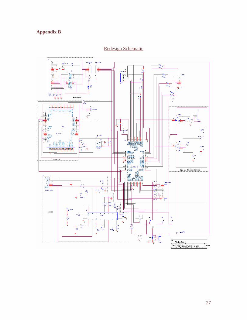
Appendix B
Redesign Schematic

28
Appendix C Assembly 1
Assembly 2
Assembly 3
Assembly 4