smart actuation for helicopter rotorblades
TRANSCRIPT

1. Introduction
The first helicopter to successfully achieve stable hovering flight and decent forward flightperformances was demonstrated in 1935 and is attributed to Louis Breguet and René Dorand[22] as shown in Figure 1. Their patent details the two coaxial counter-rotating blades whichresulted in an unprecedented level of performance, stability and safety for a rotorcraft [7].This success was soon matched by other helicopter pioneers. Henrich Focke at the FockeWulf Company and Juan de la Cierva within the Weir company demonstrated the hoveringcapabilities of a side by side rotor configuration in 1936 and 1938 respectivelly [3, 22, 47]. In1940 Sikorsky flew a single rotor helicopter configuration with three auxiliary tail rotors tonegate the counter-torque effect [22, 51] as shown in Figure 2. Sikorsky refined his design andproduced a significant number of helicopters during the war, some of which were used duringWorld War II in the Pacific [22]. After the war, this configuration was widely adopted by theemerging industry. Today almost every helicopter uses this single-rotor configuration.
Figure 1. Picture of the Breguet-Dorand helicopter.
These successes and the birth of the modern helicopter are the results of the convergenceof technology, knowledge and experience. Before Breguet and Sirkorsky flights, manyaircraft enthusiasts and pioneers built contraptions that merely hopped a few meters.Successful machines came when mature engine and mechanical technologies met scientific
©2012 Paternoster et al., licensee InTech. This is an open access chapter distributed under the terms ofthe Creative Commons Attribution License (http://creativecommons.org/licenses/by/3.0),which permitsunrestricted use, distribution, and reproduction in any medium, provided the original work is properlycited.
Smart Actuation for Helicopter Rotorblades
A. Paternoster, R. Loendersloot, A. de Boer and R. Akkerman
Additional information is available at the end of the chapter
http://dx.doi.org/10.5772/51438
Chapter 25

2 Will-be-set-by-IN-TECH
Figure 2. Picture of Sikorsky VS300 prototype.
study and a good understanding of the specificity of helicopter aerodynamics. In the1930s, engines were refined by the booming aircraft industry. They were deliveringunprecedented power-to-weight ratios [47], enabling helicopters to sustain more efficientlyhovering flights. The counter-torque effect was tackled in many ingenious ways. Breguetused two counter-rotating shafts on the same axis to balance the torques. Other concepts usedtwo and even quad-rotor configurations to balance this effect [3, 22, 34]. Patents show thelevel of engineering that was achieved to overcome the complexity of the various designs.Nevertheless, compelling forward flight performance came when the airflow asymmetry onthe rotorblades was balanced.
When hovering, each blade experiences the same distribution of incident airflow velocity.This distribution is linear and proportional to the blade radius and the blade rotation. The liftgenerated by each blade can be estimated using the lift formula
L =12
ρv2 ACl (1)
where L is the lift force on the rotorblade profile, ρ is the density of the air, v is the velocityof the airflow on the profile, A is the surface of the profile considered and Cl is the liftcoefficient. The lift coefficient is function of the pitch angle of the blade. Assuming thehelicopter is hovering, the pitch angle and the airspeed distribution are the same regardless ofthe position of the blade relative to the helicopter. The lift force of each blade is obtained fromthe integration of the lift formula along the length of a helicopter blade R
L =∫ R
0
12
ρCl(ωr)2cdr (2)
where c is the chord length of the blade profile and ω, the rotational velocity of the blade.After integration, we obtain
L =16
ρcClω2R3 (3)
As soon as the helicopter goes forward an extra velocity component is added to the velocityprofile [6, 48]. We can distinguish the retreating side where the blade motion points in theopposite direction of the helicopter motion and the advancing side where the blade motion isin the same direction as the helicopter motion alike shown in Figure 3. Therefore, the incidentairflow speed is increased on the advancing side and reduced in the retreating side. This
658 Smart Actuation and Sensing Systems – Recent Advances and Future Challenges

Smart Actuation for Helicopter Rotorblades 3
asymmetry causes a difference in the lifting capabilities of the two helicopter sides. The liftfor a blade in the retreating side becomes
L =∫ R
0
12
ρCl(ωr− vn)2cdr (4)
where vn is the component of the helicopter velocity normal to the blade and ω is the rotationalvelocity of the blade. After integration, we obtain
L =12
ρcCl
(13
ω2R3 −ωvnR2 + v2nR
)(5)
The difference between equations 3 and 5 gives the loss of lift Δ on the reatreating side due tothe helicopter overall motion
ΔL =12
ρcCl
(v2
nR−ωvnR2)
(6)
The quadratic relation between the loss of lift on the retreating side and the helicopter forwardmotion velocity shows the importance of this phenomenon. Reverse flow is another importantconsequence of the forward motion of the helicopter. It happens where the helicopter speed islarger than the velocity of the blade due to its rotation. At high speeds, this region can cover asignificant portion of the blade, meaning most of the lift is generated by the outer part of theblade. A cyclic control input was the key to balance the lift. Breguet-Dorand aircraft as well asCierva and Sikorsky helicopters used a swashplate to vary the pitch of each blade during itsrevolution [8, 22, 51, 52]. Modifying the pitch of the blade changes the angle of attack and thusthe lift for various positions of the blade around the helicopter. The angle of attack is increasedon the retreating side and decreased on the advancing side. The lift is therefore evened on thetwo sides of the helicopter. Other early rotorcrafts pioneer considered a change of the twistof the blade or the deployment of flaps at the trailing edge of the blade to control on the lift[22, 43].
Today, all helicopters use cyclic pitch control for tuning the lift as the blades rotate. Butlift can only be maintained by improving the angle of attack up to the stalling point ofthe blade profile. The maximal speed of a rotorcraft is therefore limited to the amount oflift the rotorblade can develop on the retreating side. In the case of rotorblade, the stall isdynamic, due to the unsteady nature of the flow. The vertical motion of the blade alongwith time-dependent pitching moments allows the angle of attack of the blade to exceed thequasi-static stalling angle of the profile. This favourable effect is followed by the developmentof vortexes close to the leading edge which can move towards the trailing edge causinglarge downward pitching moments [6, 22, 48]. Consequently, the rotor performance and thestability of the aircraft are reduced.
To further improve the helicopter blade performance, adaptive blade concepts are studied.The aim is to adapt the aerodynamic characteristics of the blade to maximise performance onboth the advancing and the retreating side of the blade and improve the stall performancefor large angles of attack. These systems range from morphing and changing the shape of afull blade profile to smaller devices acting on the boundary layer of the airflow to control itsseparation.
659Smart Actuation for Helicopter Rotorblades

4 Will-be-set-by-IN-TECH
Reverse flow region
Helicopter motion
Wing speed relative to air
Figure 3. Helicopter in forward flight.
2. Capabilities of smart systems in rotor blades
Smart-blades can greatly enhance the performances of modern helicopters. Localmodifications of the aerodynamic characteristics of a blade profile provide an optimisedperformance across the full blade revolution. The control of such systems conditions itscapabilities and usage. In the introduction, focus was made on the lift characteristics of theretreating side. Most concepts improve directly the lift of the profile at fixed angle of attack.Other systems increase the efficiency of the helicopter improving the stall behavior of theprofile or by reducting the vibration on the rotor. Vibrations decrease an helicopter bladeefficiency, influence the dynamic stall and generate noise. The latter is a great concern forhelicopter operating in a urban environment.
2.1. Flaps
Flaps on helicopter blades are not designed as a primary control surface like in airplanes. Theyact as a secondary control to improve the efficiency of the rotorblade by modifying the lift ofthe profile and by reducing vibrations on the rotor.
2.1.1. Active trailing edge flaps
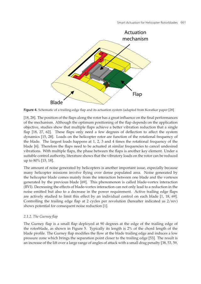
Active trailing edge flaps are flaps situated at the trailing edge that actively modify therotorblade performance. A schematic of a trailing edge flap for a helicopter blade takenfrom Koratkar [28] is shown in Figure 4. Although research has been conducted to study thepossibility to use them for control in a swashplateless configuration [49], most of the studiesfocus on their ability to reduce the vibrations of helicopter blades [1, 15, 18, 27, 28, 35, 62].The angle of the flap directly relates to a change of the bending of the blade during rotation
660 Smart Actuation and Sensing Systems – Recent Advances and Future Challenges
Smart Actuation for Helicopter Rotorblades 5
Blade
Flap
Actuationmechanism
Figure 4. Schematic of a trailing-edge flap and its actuation system (adapted from Koratkar paper [28]
[18, 28]. The position of the flaps along the rotor has a great influence on the final performancesof the mechanism. Although the optimum positioning of the flap depends on the applicationobjective, studies show that multiple flaps achieve a better vibration reduction that a singleflap [18, 27, 62]. These flaps only need a few degrees of deflection to affect the systemdynamics [15, 28]. Loads on the helicopter rotor are function of the rotational frequency ofthe blade. The largest loads happens at 1, 2, 3 and 4 times the rotational frequency of theblade [6]. Therefore the flaps need to be actuated at similar frequencies to cancel undesiredvibrations. With multiple flaps, the phase between the flaps is another key element. Under asuitable control authority, literature shows that the vibratory loads on the rotor can be reducedup to 80% [15, 18].
The amount of noise generated by helicopters is another important issue, especially becausemany helicopter missions involve flying over dense populated area. Noise generated bythe helicopter blade comes mainly from the interaction between one blade and the vortexesgenerated by the previous blade [69]. This phenomenon is called blade-vortex interaction(BVI). Decreasing the effects of blade-vortex interaction can not only lead to a reduction in thenoise emitted but also to a decrease in the power requirement. Active trailing edge flapsare actively studied to limit this effect by an individual control on each blade [1, 18, 69].Controlling the trailing edge flap at 2 cycles per revolution (hereafter indicated as 2/rev)shows potential for consequent noise reduction [1].
2.1.2. The Gurney flap
The Gurney flap is a small flap deployed at 90 degrees at the edge of the trailing edge ofthe rotorblade, as shown in Figure 5. Typically its length is 2% of the chord length of theblade profile. The Gurney flap modifies the flow at the blade trailing edge and induces a lowpressure zone which brings the separation point closer to the trailing edge [53]. The result isan increase of the lift over a large range of angles of attack with a small drag penalty [38, 53, 59,
661Smart Actuation for Helicopter Rotorblades

6 Will-be-set-by-IN-TECH
Gurney flap
Chord line
Chord length
Figure 5. Sketch of a Naca 23012 profile with a 2% Gurney flap.
68]. Although the Gurney flap induces pitching moment, it provides a beneficial improvementof the efficiency of the rotorblade profile for the hovering situation [68]. In forward flight, theGurney flap provides the blade with additional lift on the retreating side to balance the liftdistribution [59]. For large forward velocity, the Gurney flap improves the airfoil behaviourin light stall conditions, which increases directly the flight envelope of a helicopter [68]. Thebehaviour of the Gurney flap is related to its length and placement. Studies about the lengthof the Gurney flap show an increase in drag and pitching moments with increasing lengths[38, 53, 63, 68]. Depending on the application, the Gurney flap length is limited to the pointwhere these disadvantages outweigh its benefits in lift and stall characteristics.
Furthermore, the Gurney flap can have a positive effect on blade-vortex interaction. Similarlyto a trailing edge flap, the Gurney flap acts on the blade mechanical behaviour [68]. Actuatingthe Gurney flap at 2/rev with suitable control would lead to a decrease in vibration and noisein a similar way than active trailing edge flaps [69].
2.2. Morphing blades
The idea behind morphing blades is to change the aerodynamic characteristics of the bladeby a continuous change in its shape. This approach is inspired by the way birds and flyinganimals are modifying their wings to adapt to the various situations they encounter whileflying. Most of these solutions involve a stiff structure that supports the loads and a flexibleskin to keep the outer surface of the rotorblade without discontinuities.
2.2.1. Variable droop leading edge
The concept behind the nose drop is to advance the front part of the profile at an angle.It increases the profile as well as the curvature, as shown in Figure 6. The variable droopleading edge is used to alleviate the dynamic stall by ensuring that the flow passes smoothlyover the leading edge for high angles of attack [32]. Although the lift is increased during thedownward motion of the leading edge [32], the maximum lift is reduced by 10% [13, 21, 37].More significantly, the drag and pitching moments are reduced by 50% [13]. The variabledroop leading edge concept provides a decrease in helicopter vibrations and loads due tothe suppression of dynamic stall within the retreating blade region. However, the helicoptermaximum speed is reduced due to a decrease in lift when the droop nose is deployed.Therefore, the variable droop leading edge is studied in combination with the Gurney flap tonegate the lift reduction [14]. This concept can also be applied to reduce the noise generatedby a helicopter [9].
662 Smart Actuation and Sensing Systems – Recent Advances and Future Challenges

Smart Actuation for Helicopter Rotorblades 7
Figure 6. Sketch of the VR-12 profile used for wind tunnel testing at NASA Research Center from Leepaper [32].
2.2.2. Camber change
Changing the camber of a profile increases its lift for the same chord length [54]. The benefitis a larger flight envelope of the helicopter by improving the lift on the retreating side of therotorcraft in the same way than the Gurney flap concept. Once again harmonic actuationat 2/rev could reduce the noise and the vibratory loads on the rotor, improving the rotorperformance [18, 20]. Most studies on this concept consider the plane as the main application,envisioning morphing flaps as a main control surface [39].
2.2.3. Active-twist
Among early helicopter prototypes, some developer considered cyclic twist control [43] forchanging the lift of the rotating blades. The idea behind active twist is to modify the twist andthe torsional stiffness of rotating blade not only to improve the lift and the global helicopterperformance but also to actively damp vibrations. Early experiments on active twist involvedchanging the twist of the helicopter blade at the root of the blade [2]. Later experiments useda distributed actuation actuation system to modify the blade twist [46, 50, 58, 66]. In a similarmanner to the active trailing edge, the placement and the number of actuators modify theamount of vibration that are reduced. Thakkar study shows that up to 69% of reduction invibrations can be achieved with the actuation of two sections [58]. Wind tunnel tests on ahelicopter model demonstrated a 95% reduction in vibrations [66]. In the tests, each of thefour blades mounted on the helicopter model was equipped with 24 actuators bonded ontothe skin of the blade. Although only up to 1.4 degree of change in the pitching angle ofthe blade was achieved, torsional vibrations at 3/rev and 5/rev were successfully damp. Inaddition, the noise generated by the blade-vortex interaction can be reduced by up to 90%using an appropriate control of the blade twist [5].
2.2.4. Extended trailing edge
The amount of lift a profile can deliver depends on its chord length. For the same geometry,the lift is proportional to the blade surface area as shown in equation 1. Therefore, extendingthe chord length of a profile increases the lift generated. Studies on an extended trailing edge
663Smart Actuation for Helicopter Rotorblades
8 Will-be-set-by-IN-TECH
active blade have shown an increase in the lift without significant increase in the lift-to-dragratio [36].
2.3. Active flow control
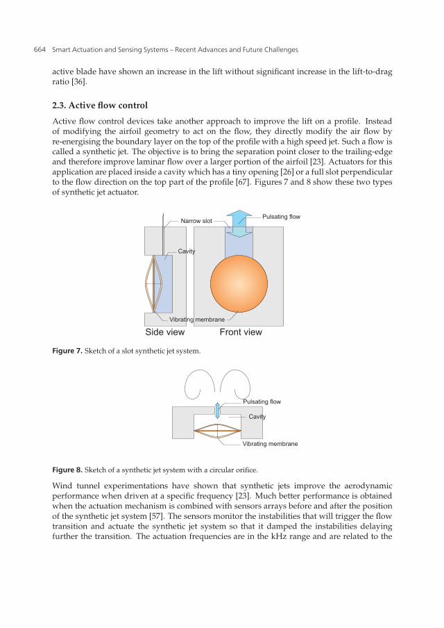
Active flow control devices take another approach to improve the lift on a profile. Insteadof modifying the airfoil geometry to act on the flow, they directly modify the air flow byre-energising the boundary layer on the top of the profile with a high speed jet. Such a flow iscalled a synthetic jet. The objective is to bring the separation point closer to the trailing-edgeand therefore improve laminar flow over a larger portion of the airfoil [23]. Actuators for thisapplication are placed inside a cavity which has a tiny opening [26] or a full slot perpendicularto the flow direction on the top part of the profile [67]. Figures 7 and 8 show these two typesof synthetic jet actuator.
Vibrating membrane
Narrow slot
Cavity
Side view Front view
Pulsating flow
Figure 7. Sketch of a slot synthetic jet system.
Vibrating membrane
Pulsating flow
Cavity
Figure 8. Sketch of a synthetic jet system with a circular orifice.
Wind tunnel experimentations have shown that synthetic jets improve the aerodynamicperformance when driven at a specific frequency [23]. Much better performance is obtainedwhen the actuation mechanism is combined with sensors arrays before and after the positionof the synthetic jet system [57]. The sensors monitor the instabilities that will trigger the flowtransition and actuate the synthetic jet system so that it damped the instabilities delayingfurther the transition. The actuation frequencies are in the kHz range and are related to the
664 Smart Actuation and Sensing Systems – Recent Advances and Future Challenges

Smart Actuation for Helicopter Rotorblades 9
airflow speed [10]. Most of the literature focuses on fixed wind tunnel test [10] but simulationsshow a potential increase in the maximum lift of an airfoil by 34% with an increase in themaximum stall angle of a profile [17]. These characteristics make synthetic jets system verypromising for improving the characteristics of a profile for helicopter applications.
3. Challenges for smart-systems inside helicopter blades
Smart-systems need to answer challenges specific to the integration in helicopter blades. Thecombination of these challenges make smart-blade concepts very difficult to design.
3.1. Weight and space constraints
The weight and space are the main constrains in helicopter blades. Helicopter blades aredesigned to handle large centrifugal loads. The structural material takes most of the sectionof a rotorblade. Carbon fibre composites provide strength in the direction of the blade andreinforced layers give the blade impact resistance. The only space available is in the tailof the profile. Therefore, it is very difficult to integrate a system directly in the rotorbladeskin for structural reasons. Concerning the weight, not only it cannot increase much, but itsdistribution in the profile should not affect the chordwise balance of the blade. Therefore, anyweight added behind the aerodynamic centre needs to be compensated by an extra mass in theleading edge. For the whirl tower test of the SMART active flap rotor, weight was added in theleading edge to maintain the blade balance [55]. This constraint makes distributed and lightsystems like the active twist very relevant to maintain the distribution of mass along the profilechord. In comparison, the variable droop leading edge requires a very heavy mechanism todeform the leading edge of the profile that would change completely the weight distributionaround the aerodynamic centre [29].
3.2. Mechanical constraints
Mechanical constraints are significant in a helicopter blade. The centrifugal loads are by farthe main issue. The centrifugal loads come from the large rotational speeds of the blade. Thecentrifugal acceleration a is calculated with the following formula
a = ω2r (7)
where ω is the rotational speed of the blade in rad/sec and r is the position along the lengthof the blade. An 8m rotorblade rotating at 250rpm will generate close to 560g of accelerationat the tip. Because of the aerodynamics of an helicopter blade, the active system needs tobe integrated near the tip of the blade where the centrifugal acceleration is the largest. Thecentrifugal loads resulting from the acceleration depend on the mass of the actuation system.Thus, a very light system does not lead to large loads. Some small actuation systems are verysmall and robust. The "Squiggle" linear drive motor, developed by NewScale technology,features a shock resistance of 2500g [40, 64]. For larger mechanisms most of the designs limitthe load transfer along the blade [42, 55, 60]. Hence the design can be approximated to abi-dimensional structure that is extended along the blade axis. For distributed systems thatuse patch actuators bonded onto the structure, like the active-twist technology developed byDLR, the actuators are being supported by the blade structure [46]. The main concern withthese actuators is related to the deformation of the blade during its rotation. The peak strain
665Smart Actuation for Helicopter Rotorblades
10 Will-be-set-by-IN-TECH
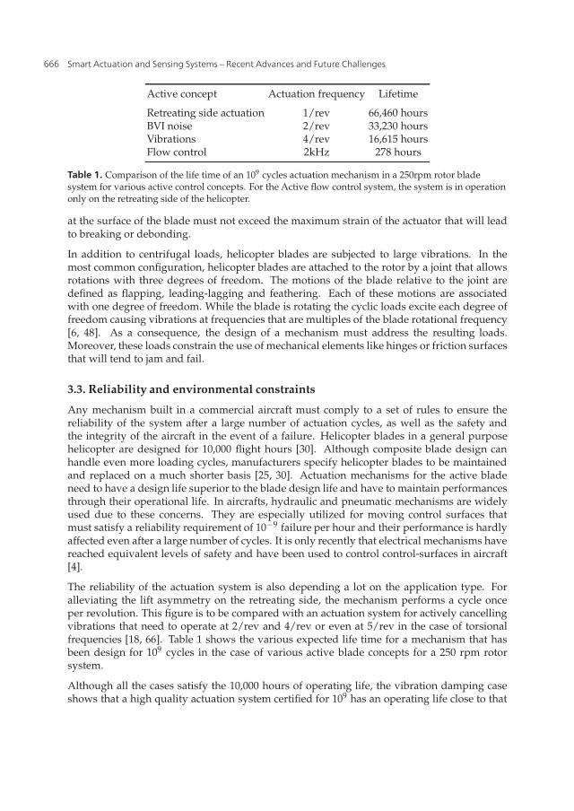
Active concept Actuation frequency Lifetime
Retreating side actuation 1/rev 66,460 hoursBVI noise 2/rev 33,230 hoursVibrations 4/rev 16,615 hoursFlow control 2kHz 278 hours
Table 1. Comparison of the life time of an 109 cycles actuation mechanism in a 250rpm rotor bladesystem for various active control concepts. For the Active flow control system, the system is in operationonly on the retreating side of the helicopter.
at the surface of the blade must not exceed the maximum strain of the actuator that will leadto breaking or debonding.
In addition to centrifugal loads, helicopter blades are subjected to large vibrations. In themost common configuration, helicopter blades are attached to the rotor by a joint that allowsrotations with three degrees of freedom. The motions of the blade relative to the joint aredefined as flapping, leading-lagging and feathering. Each of these motions are associatedwith one degree of freedom. While the blade is rotating the cyclic loads excite each degree offreedom causing vibrations at frequencies that are multiples of the blade rotational frequency[6, 48]. As a consequence, the design of a mechanism must address the resulting loads.Moreover, these loads constrain the use of mechanical elements like hinges or friction surfacesthat will tend to jam and fail.
3.3. Reliability and environmental constraints
Any mechanism built in a commercial aircraft must comply to a set of rules to ensure thereliability of the system after a large number of actuation cycles, as well as the safety andthe integrity of the aircraft in the event of a failure. Helicopter blades in a general purposehelicopter are designed for 10,000 flight hours [30]. Although composite blade design canhandle even more loading cycles, manufacturers specify helicopter blades to be maintainedand replaced on a much shorter basis [25, 30]. Actuation mechanisms for the active bladeneed to have a design life superior to the blade design life and have to maintain performancesthrough their operational life. In aircrafts, hydraulic and pneumatic mechanisms are widelyused due to these concerns. They are especially utilized for moving control surfaces thatmust satisfy a reliability requirement of 10−9 failure per hour and their performance is hardlyaffected even after a large number of cycles. It is only recently that electrical mechanisms havereached equivalent levels of safety and have been used to control control-surfaces in aircraft[4].
The reliability of the actuation system is also depending a lot on the application type. Foralleviating the lift asymmetry on the retreating side, the mechanism performs a cycle onceper revolution. This figure is to be compared with an actuation system for actively cancellingvibrations that need to operate at 2/rev and 4/rev or even at 5/rev in the case of torsionalfrequencies [18, 66]. Table 1 shows the various expected life time for a mechanism that hasbeen design for 109 cycles in the case of various active blade concepts for a 250 rpm rotorsystem.
Although all the cases satisfy the 10,000 hours of operating life, the vibration damping caseshows that a high quality actuation system certified for 109 has an operating life close to that
666 Smart Actuation and Sensing Systems – Recent Advances and Future Challenges
Smart Actuation for Helicopter Rotorblades 11
of the blade. Therefore, it would be very difficult to qualify an actuation system for dampingvibration at 6/rev. For flow control devices, very much higher quality actuators are requiredto be certified for active flow control.
Finally, helicopters need to operate under a large range of environmental conditions. Bladesare certified to perform over a large temperature range: from high altitude freezing conditionsto high temperatures and with very high moisture content. It is therefore very difficultto design a fail-safe mechanism in these conditions, especially on small helicopters whichdo not have a de-icing system. Furthermore, some specific environments subject helicoptercomponents to very difficult conditions such as sea and desert environments where corrosionand erosion are important matters.
3.4. Failure
In addition to being designed to exceed the life time of the blade, the active blade actuationsystem must also be developed not to influence the performance of the helicopter in theevent of a failure. For distributed systems like the active-twist, if the patch actuators are notworking, they will not reduce the performance of the blade profile. On the contrary, for theGurney flap, the variable droop leading edge and the trailing edge active blade concept, inthe event of a jamming, the blade profile will be modified during the full rotation of the rotorblade. Hence, care must be taken to make sure the helicopter is stable and able to be controlledwith a modified profile. Furthermore, in the event of a power failure, the mechanism must goback to its initial state. This can be done by prestressing the mechanism or making sure thatthe aerodynamic loads are sufficient to bring the mechanism back to its inactive state.
3.5. Power requirement
To operate an actuator in a rotorblade, power needs to be transfered from the helicopter to theblades. Electrical, pneumatic and hydraulic power can be provided to a rotating blade by theuse of specialized rotor mounts which add to the complexity of the rotor hub [24]. The typeand the amount of power that can be drawn for an actuation system is a serious limitation tosome active system. Large helicopter blades include a de-icing system for high altitude flight.Such a system draws up to 1kW of electrical power that is transfer to each blade. This gives agood estimation of the power available for an electrical actuation system.
3.6. Complexity of the system
Developing smart systems for helicopters is tremendously complex due to the number and thevariety of the domains involved. For designing an active helicopter rotorblade, knowledge isrequired not only in aerodynamics and mechanics, but also in control, material science andelectronics. Simulating for validating a concept, selecting of a suitable actuation technologyand defining an application demand skills in all these domains. In order to move fromresearch and laboratory experiments to flying prototypes and commercial products, theEuropean union has created a Consortium within the Clean Sky Joint Technology Initiativeto bring various research partners together. The Green Rotorcraft Consortium, among itslines of research, manages the evaluation of the Gurney flap technology to improve helicopterperformance and noise reduction with both academic and industrial partners [16].
667Smart Actuation for Helicopter Rotorblades

12 Will-be-set-by-IN-TECH
4. Piezoelectric actuators for smart-rotor blade systems
Many actuation technologies are available to actuate every smart blade concepts. Amongthem, piezoelectric actuators have a tremendous potential to meet and exceed the variousrequirements of these specific applications. This section focuses on piezoelectric actuatorsand their potential for the actuation of active systems for helicopter blades.
4.1. Piezoelectricity
Piezoelectric materials are materials that have the property to convert mechanical energyinto electrical energy. When such a material is subjected to a strain, an electrical charge iscreated inside the material. This property is called the direct piezoelectric effect. Additionally,when the material is subjected to an electrical field, it deforms according to the electricalfield magnitude. This is called the converse piezoelectric effect. A piezoelectric material ischaracterized by the piezoelectric strain constant dij which relates the strain to the electricalfield. The subscript i indicates the direction of the applied electrical field and the subscript jindicates the direction of the deformation. Prior to be used, the piezoelectric material is poled.Conventionally the poling direction is along the vertical axis (3-axis) as shown in Figure 9.When an electrical field is applied in the poling direction, the material is contracting in thatdirection and extending in other directions (1- and 2-axis). Changing the direction of theelectrical field will result in a contraction along the 1- and 2-axis and extension along thevertical axis. To quantify these piezoelectric effects, the direct and shear strains are relatedto the electrical field by the following constants: d31 = d32, d33, d25 = d15. Equation 8 is theequilibrium equation that relates the electrical field E to the strain and shear components ofthe material (ε and γ) when no mechanical constraint is applied on the material.
3
2
1
Electrodes
Poling direction
Figure 9. Axis reference system for piezoceramic components.
⎛⎜⎜⎜⎜⎜⎜⎝
ε1ε2ε3
γ23γ31γ12
⎞⎟⎟⎟⎟⎟⎟⎠
=
⎡⎢⎢⎢⎢⎢⎢⎣
0 0 d310 0 d320 0 d330 d25 0
d15 0 00 0 0
⎤⎥⎥⎥⎥⎥⎥⎦×
⎛⎝ E1
E2E3
⎞⎠ (8)
668 Smart Actuation and Sensing Systems – Recent Advances and Future Challenges

Smart Actuation for Helicopter Rotorblades 13
Name d31(m/V) d33(m/V) e33 CT(◦C) ρ(kg/m3) S33(m2/N)
PZT-SP4 -1.23e-10 3.1e-10 1300 325 7500 1.81e-11PZT-5A1 -1.85e-10 4.4e-10 1850 335 7500 2.07e-11PZT-5H -2.74e-10 5.93e-10 3400 193 7500 2.083e-11
PZT-PSt-HD -1.9e-10 4.5e-10 1900 345 7500 2.1e-11PZT-PSt-HPSt -2.9e-10 6.4e-10 5400 155 8000 1.8e-11PZT-PIC-255 -1.8e-10 4.0e-10 1750 350 7800 2.07e-11PZT-PIC-151 -2.1e-10 5.0e-10 2400 250 7800 1.9e-11
Table 2. Table of some piezoceramic materials. PZT-SP4 and PZT-5A1 are from Smart-MaterialCompany. PZT-5H is taken from Chopra review on actuators [15]. PZT-PSt-HD and PZT-PSt-HPSt arefrom Piezomechanik Company. Finally, PZT-PIC-255 and PZT-PIC -151 are from Physic InstrumenteCompany [45].
Consequently, the knowledge of the 3 constants d31, d33 and d15 is sufficient to fullycharacterize the electromechanical properties of a piezoelectric material. A deformation alongthe 1- and 2-axis which is characterized by the d31 coefficient is called the d31 effect and adeformation along the 3-axis is called the d33 effect as the d33 coefficient characterizes thisdeformation as shown in Figure 10.
3
2
1
Electrode
Poling direction
d effect33
d effect31
Electrical field
Figure 10. Piezoelectric effects for an electrical field applied in the poling direction.
4.2. Types of piezoelectric actuators
Although some polymers can exhibit piezoelectric characteristics [61], most piezoelectricactuators are based on piezoceramics. Piezoceramic materials have been widely studied andused since the second world war to manufacture ultrasonic transducers. Table 2 lists somepiezoceramics available from manufacturers.
4.2.1. d31 effect actuators
Piezoceramic actuators using the d13 effect are based on the fact that a through-thicknesselectrical field will contract the material’s width and length. The components manufactured
669Smart Actuation for Helicopter Rotorblades

14 Will-be-set-by-IN-TECH
using this principle are consequently laminates of fine piezoceramic sheets. Electrodes arebonded on the upper and lower faces of the piezoceramic patch. Applying a voltage throughthe patch’s thickness causes a contraction in the plane of the patch as shown in Figure 11.These can be easily bonded or embedded inside a structure, thanks to their low weight andvolume. Thus, they are mainly used to manufacture unimorph and bimorph structures.
+ -
Poling direction
Electrode
Electrical field
Displacement
Figure 11. Principle of a piezoelectric laminar actuator
4.2.2. d33 effect actuators
Piezoceramic actuators using the d33 effect are based on the fact that a through-thicknesselectrical field will modify the material’s thickness. Within piezoceramics, the d33 coefficientis always more important than the d31 coefficient, therefore using the d33 effect is preferable.Consequently, there are many types of actuators that try to take advantage of the larger d33coefficient using various geometries.
• Stack actuatorStack actuators use the d33 effect to achieve deflection. They consist of multiple layersof piezoceramic plates separated by electrodes as shown in Figure 12. This configurationallows long elements to be made for higher displacement capabilities while high voltageis not needed to obtain high electrical fields if the piezoceramic layers are small enoughbetween two electrodes. Stack actuators are capable of delivering higher forces thanlaminar actuators as they are fully using the highest strain coefficient available.
• Macro Fibre Composites (MFC) & Active Fibre Composite (AFC)Long piezoceramic components have better displacement capabilities. Active FibreComposite (AFC) consists of piezo ceramic fibres embedded into a protective polymersubstrate and poled into the fibre direction to use the highest strain coefficient.Interdigitated electrodes bonded onto the fibres ensure high electrical fields. The voltagerequired by these components depends on the fibre diameter and the distance betweenelectrodes. Compared with laminar actuators, these components require less voltageto achieve the same force and displacement. Macro Fibre Composite exploit the sameprinciples as AFC, except that they are made of fibres having an improved contact withelectrodes, which plays an important role in the electrical field magnitude inside thematerial. Furthermore, those actuators are much more flexible than a strip made of thesame material.
670 Smart Actuation and Sensing Systems – Recent Advances and Future Challenges

Smart Actuation for Helicopter Rotorblades 15
Electrodes
+-
1
3
Poling direction Electrical Field
Displacement
Figure 12. Principle of a piezoceramic stack actuator.
Piezoelectric fibres
Epoxy Resin
Interdigitated electrodes
Poling direction Displacement
+ -
Figure 13. Sketch of an Active Fibre Composite (AFC) actuator.
4.2.3. d15 effect actuators
The d15 effect is a shearing effect. The material shears in the 3-1 or 3-2 plane when an electricalfield is applied in the 1-axis or 2-axis respectively, perpendicular to the poling direction asshown in Figure 14.
The d15 shearing effect can be used to manufacture a tube actuator that twists when actuatedas shown in Figure 15. Centolanza has discussed the manufacturing of an induced shearactuator and its testing [12]. Kim has tested the same component with feedforward controland pointed out fatigue and heating issues [27]. Their conclusions are that such an actuatoris a promising option and more studies of the piezoceramic material would improve theirmodels accuracy.
671Smart Actuation for Helicopter Rotorblades

16 Will-be-set-by-IN-TECH
3
1
2
Poling direction
Electrical field
γ23Shear strain
Figure 14. d15 effect in piezoceramics.
3
1
2
+ +
+
- -
-
Poling direction
Electrical field
Electrode θ
Figure 15. Twisting motion for the d15 effect in a shear tube actuator.
4.3. Performances
4.3.1. Block force and free displacement
The performance of piezoelectric actuators is evaluated in block force and free displacement.The block force is the maximum force the piezoelectric actuator can deliver when clamped.The free displacement is the displacement achieved by the actuator when no force is appliedon it. These two parameters depend on the values of the piezoelectric strain coefficient, theelectrical field inside the material and the geometry of the actuator. For a d31 patch actuatorthe free displacement Δ and the block force Fblock can be directly derived from the Equation 8.
Δ = d31LVt
(9)
672 Smart Actuation and Sensing Systems – Recent Advances and Future Challenges
Smart Actuation for Helicopter Rotorblades 17
where d31 is the piezoelectric strain coefficient, L the length of the actuator, V the appliedvoltage and t the distance between the two electrodes.
Fblock =d31 AV
S11t(10)
where A is the cross-section area of the actuator, t the distance between two electrodes andS11 the compliance in the plane of the actuator.
Piezoelectric actuators provide large blocking forces but only very low displacements.Therefore, typical mechanisms that involve piezoelectric components contain systems toamplify the displacement of the actuator. The amplification can be achieved by the use oflevel arms or by the integration of the piezoelectric component in a structure providing thatamplification. Cedrat Technologies develops these systems based on stack actuators [11, 44].
4.4. Bandwidth
The first widespread use of piezoelectric actuators was for manufacturing acoustic sources forsonar because of their large actuation frequency bandwidth. Overall, piezoelectric actuatorshave a very small actuation time and can achieve large motion speed and acceleration. CedratTechnologies manufactures actuators with a response time below 1ms [11]. Moreover, thetypical resonance frequency for piezoelectric actuators is in the kHz range, leaving a verycomforting margin for structural applications [11, 45].
4.5. Power consumption and voltage
The power consumption of piezoelectric actuators depends on the type of actuation.Integrated inside an electrical circuit, a piezoelectric actuator behaves like a capacitor.Under harmonic actuation, the energy required to charge the piezoelectric actuator can berecuperated in the system for the next charge. When fast positioning is required, the electricalcomponents which drive the piezoelectric actuator must be able to provide large currents. Forthe discharge, the circuit and its components must be able to dissipate quickly the energystored in the piezoelectric. Therefore, active systems using harmonic actuation only needaround 100W in operation, while a fast actuation system requires close to 1000W of powerdepending on the actuation profile. However, the main problem is not the amount of electricalpower required but the time during which the power is required.
4.6. Reliability and operational environment
Piezoelectric actuators are very reliable and can perform a large number of cycles undergood operating conditions. For instance piezoelectric stack actuators manufactured by PhysikInstrumente feature 109 cycles [45]. Cedrat technologies is developing high end actuatorswith 1010 cycles before failure [11]. Furthermore, piezoelectric actuators can operate in veryharsh environments. Physik Instrumente provides piezoelectric stack actuators capable ofoperating in cryogenic environments [45]. Moreover, piezoelectric actuators can operate athigh temperatures as long as the Curie temperature is not reached. The Curie temperature isthe temperature at which the piezoelectric material looses its electro-mechanical coupling andthis temperature is usually higher than 200◦C as shown in Table 2.
673Smart Actuation for Helicopter Rotorblades
18 Will-be-set-by-IN-TECH
4.7. Applications
The relevance of piezoelectric actuators for active blade systems comes from the large specificwork they can output [41] while being small and easily integrable. Moreover their reliabilitymakes them suitable for safely powering mechanisms in smart blade concepts.
Many actuation systems for the active trailing-egde rotorblade are actuated using amplifiedstack actuators [33, 44, 56]. Other designs use piezoelectric patch actuators bonded onto abeam [28] or piezoelectric shear actuators built as a torsional actuator as shown in Figure 15[12].
Some studies on the design of airfoils with controllable camber involve stack actuators inside astructure that convert and amplify the motion into a change of curvature of the airfoil [19, 20].
For the deployment of the Gurney flap at the trailing edge, bimorph piezoelectric actuationmechanisms are being studied [59], as well as more complex structures to amplify thedisplacement of piezoelectric patch actuators and MFCs [42]. AFC and MFC actuators havealso been tested successfully for the active-twist application [65]. They provide distributedstrain over all the rotorblade surface to successfully twist the blade under operating conditions[46, 50].
Research on flow control systems has considered piezoelectric diaphragms to deliver enoughairflow speed for synthetic jets and achieve proper flow control [31, 67].
5. Conclusion
Today’s helicopters are the results of some tremendous work and collaborations in mechanicalengineering and aeronautics. The first successes came from inventors that could understandthe complexity of a rotating lift surface while designing advanced mechanical mechanisms.To further improve today’s helicopters, research is focussing on active blade systems to adaptthe aerodynamic properties of the blade to the local aerodynamic conditions. Two aspects areespecially studied: enhancing the lift on the retreating side and alleviating the large vibrationsin the rotor. Both these aspects will provide improvements on the helicopter performances.Besides the efficiency of the rotor system, the objective is to push the flight envelope of theseaircrafts and to make them faster, smoother and quieter.
Many active concepts are being studied but they all face a large number of challenges tobe successfully integrated within a helicopter blade. The rotation speed generates criticalloads on the blade and any system within it. With the helicopter blade being the componentproviding both lift and control in a helicopter, any mechanism influencing its behaviouris required to be durable, reliable and safe. Actuation of the active system is the mostcritical aspect of a smart adaptive blade. Piezoelectric actuators have the potential to providecompelling actuation for these systems. They are actively tested for many of these concepts.Their toughness, size and reliability make them especial candidates for delivering the requiredmechanical power.
The key aspect of helicopter progress remains in the collaboration between partners fromvarious domains, combinig different skills and expertise, to answer these challenges anddevelop tomorrow’s aircrafts.
674 Smart Actuation and Sensing Systems – Recent Advances and Future Challenges

Smart Actuation for Helicopter Rotorblades 19
Acknowledgements
This project is funded by the European Union in the framework of the Clean Sky program -Green Rotorcraft.
Author details
Paternoster A.Chair of Applied Mechanics, Faculty of Engineering Technology, University of Twente, Enschede, TheNetherlandsChair of Production Technology, Faculty of Engineering Technology, University of Twente, Enschede,The Netherlands
Loendersloot R. and de Boer A.Chair of Applied Mechanics, Faculty of Engineering Technology, University of Twente, Enschede, TheNetherlands
Akkerman R.Chair of Production Technology, Faculty of Engineering Technology, University of Twente, Enschede,The Netherlands
6. References
[1] Altmikus, A., Dummel, A., Heger, R. & Schimke, D. [2008]. Actively controlled rotor:aerodynamic and acoustic benefit for the helicopter today and tomorrow, 34th EuropeanRotorcraft Forum, Liverpool.
[2] Barrett, R. & Stutts, J. [1997]. Design and testing of a 1/12th-scale solid state adaptiverotor, 491.
[3] Bennett, J. [1944]. Helicopter and Gyroplane, US patent 2,344,967 .[4] Bennett, J., Mecrow, B., a.G. Jack, Atkinson, D., Sheldon, S., Cooper, B., Mason, G., Sewell,
C. & Cudley, D. [2005]. A prototype electrical actuator for aircraft flaps and slats, IEEEInternational Conference on Electric Machines and Drives, 2005. pp. 41–47.
[5] Booth, E. & Wilbur, M. [n.d.]. Acoustic Aspects of Active-Twist Rotor Control, Journal ofthe American Helicopter Society 49(1): 8.
[6] Bramwell, A., Done, G. & Balmford, D. [2000]. Bramwell’s Helicopter Dynamics, Elsevier.[7] Breguet, L. [1933]. Revolving Supporting Surfaces, US Patent 1,919,089 .[8] Breguet, L. [1935]. Flying machine having revolving supporting surfaces, US Patent
1,986,709 .[9] Breitbach, E. & Büter, A. [1996]. The main sources of helicopter vibration and
noise emissions and adaptive concepts to reduce them, Journal of Structural Control3(1-2): 21–32.
[10] Cattafesta, L., Song, Q., Williams, D., Rowley, C. & Alvi, F. [2008]. Progress in AerospaceSciences Active control of flow-induced cavity oscillations, Progress in Aerospace Sciences44: 479–502.
[11] CedratTechnologies [2012]. CEDRAT TECHNOLOGIES: Innovation in Mechatronics,www.cedrat-technologies.com .
[12] Centolanza, L., Smith, E. & Munksy, B. [2002]. Induced-shear piezoelectric actuators forrotor blade trailing edge flaps, Smart Materials and Structures , February .
675Smart Actuation for Helicopter Rotorblades
20 Will-be-set-by-IN-TECH
[13] Chandrasekhara, M. [2007]. Compressible dynamic stall vorticity flux control using adynamic camber airfoil, Sadhana 32(1-2): 93–102.
[14] Chandrasekhara, M. [2010]. Optimum Gurney flap height determination for lost-liftrecovery in compressible dynamic stall control, Aerospace Science and Technology14(8): 551–556.
[15] Chopra, I. [2002]. Review of State of Art of Smart Structures and Integrated Systems,AIAA/ASME/ASCE/AHS/ASC Structures, Structural Dynamics, and Materials Conference,Seattle, WA, AIAA Journal 40(11).
[16] CleanSky [2012]. Clean Sky Joint Technology Initiative, http://www.cleansky.eu .[17] Duvigneau, R. & Visonneau, M. [2006]. Simulation and optimization of stall control for
an airfoil with a synthetic jet, Aerospace Science and Technology 10(4): 279–287.[18] Friedmann, P., de Terlizzi, M. & Myrtle, T. [2001]. New developments in vibration
reduction with actively controlled trailing edge flaps, Mathematical and ComputerModelling 33(10-11): 1055–1083.
[19] Gandhi, F. & Anusonti-Inthra, P. [2008]. Skin design studies for variable cambermorphing airfoils, Smart Materials and Structures 17(1): 015025.
[20] Gandhi, F., Frecker, M. & Nissly, A. [2008]. Design Optimization of a ControllableCamber Rotor Airfoil, AIAA Journal 46(1): 142–153.
[21] Geissler, W. & Trenker, M. [2002]. Numerical investigation of dynamic stall control by anose-drooping device, Technical Report C.
[22] Gordon Leishman, J. [2006]. Principles of Helicopter Aerodynamics.[23] Greenblatt, D. & Wygnanski, I. [2000]. The control of flow separation by periodic
excitation, Progress in Aerospace Science 36.[24] Haber, A. & Jacklin, S. [2002]. Development, manufacturing, and component testing of
an individual blade control system for a UH-60 Helicopter Rotor, American Helicopter .[25] Head, E. [2012]. Blade Trouble | Vertical - Helicopter News.[26] Hong, G. [2006]. Effectiveness of micro synthetic jet actuator enhanced by flow instability
in controlling laminar separation caused by adverse pressure gradient, Sensors AndActuators 132(2006): 607–615.
[27] Kim, J.-S., Wang, K. & Smith, E. [2007]. Development of a resonant trailing-edge flapactuation system for helicopter rotor vibration control, Smart Materials and Structures16(6): 2275–2285.
[28] Koratkar, N. & Chopra, I. [n.d.]. Wind Tunnel Testing of a Mach-Scaled Rotor Model withTrailing-Edge Flaps, Journal of the American Helicopter Society 47(4): 263–272.
[29] Kota, S., Ervin, G. & Osborn, R. [2008]. Design and Fabrication of an Adaptive LeadingEdge Rotor Blade, American Helicopter Society Annual Forum .
[30] Kwon, J.-H., Hwang, K.-J., Kim, S.-S., Kim, P.-J. & Kim, C.-S. [n.d.]. Fatigue life evaluationin composite rotor blade of multipurpose helicopter, Proceedings 6th Russian-KoreanInternational Symposium on Science and Technology. KORUS-2002 (Cat. No.02EX565), IEEE,pp. 15–20.
[31] Lee, C., Hong, G., Ha, Q. & Mallinson, S. [2003]. A piezoelectrically actuated microsynthetic jet for active flow control, Sensors And Actuators 108(April 2003): 168–174.
[32] Lee, S. & McAlister, K. [1993]. Characteristics of deformable leading edge for highperformance rotor, AIAA Journal 35.
[33] Lee, T. & Chopra, I. [2001]. Design of a piezostack driven trailing-edge flap actuator forhelicopter rotors, Smart Mater. Struct. 10: 15–24.
[34] LePage, L. [1936]. Flight on rotating wings, Journal of the Franklin Institute 222.
676 Smart Actuation and Sensing Systems – Recent Advances and Future Challenges
Smart Actuation for Helicopter Rotorblades 21
[35] Lim, I.-G. & Lee, I. [2009]. Aeroelastic analysis of rotor systems using trailing edge flaps,Journal of Sound and Vibration 321(3-5): 525–536.
[36] Liu, T., Montefort, J., Liou, W., Pantula, S. R. & Shams, Q. a. [2007]. Lift Enhancement byStatic Extended Trailing Edge, Journal of Aircraft 44(6): 1939–1947.
[37] Martin, P., McAlister, K. & Chandrasekhara, M. [2003]. Dynamic Stall Measurements andComputations for a VR-12 Airfoil with a Variable Droop Leading Edge, Technical report.
[38] Maughmer, M. & Bramesfeld, G. [2008]. Experimental Investigation of Gurney Flaps,Journal of Aircraft 45(6): 2062–2067.
[39] Monner, H. [2001]. Realization of an optimized wing camber by using formvariable flapstructures, Aerospace Science and Technology 5: 445–455.
[40] NewScaleTechnologies [2012]. New Scale Technologies - precision motion for microimaging and vision systems, http://www.newscaletech.com/ .
[41] Paternoster, A., DeBoer, A., Richard, L. & Remko, A. [2010]. Actuators for SmartApplications, Proceedings of the ASME 2010 Conference on Smart Materials, AdaptiveStructures and Intelligent Systems, Asme.
[42] Paternoster, A., Loendersloot, R., de Boer, A. & Akkerman, R. [2011]. GeometricOptimisation of Hinge-less Deployment System for an Active Rotorblade, Proceedingsof the ASME 2011 Conference on Smart Materials, Adaptive Structures and Intelligent Systems,ASME.
[43] Pescara, R. [1923]. Screw propeller of helicopter flying machines, US Patent 1,449,129 .[44] Petitniot, J., Rochettes, H.-M. & Leconte, P. [2002]. Experimental assessment and further
development of amplified piezo actuators for active flap devices, Actuator, number June,pp. 10 – 12.
[45] PhysikInstrumente [2012]. PI Leader in: Precision Nano-Positioning & PiezoEngineering, NanoAutomation, Piezo Stage, Hexapod, PZT, Piezo Actuator, Transducer:Sub-Nanometer Resolution, Metrology, Photonic Packaging Automation, Piezo LinearMotor, Steering Mirror, Translation, http://www.physikinstrumente.com/ .
[46] Riemenschneider, J., Opitz, S., Schulz, M. & Plaß meier, V. [2010]. Active Twist Rotor forWind Tunnel Investigations, Proceedings of the ASME 2010 Conference on Smart Materials,Adaptive Structures and Intelligent Systems, Vol. 2010, ASME, pp. 371–378.
[47] Rosen, K. [n.d.]. A Prospective: The Importance of Propulsion Technology to theDevelopment of Helicopter Systems with a Vision for the Future. The 27th AlexanderA. Nikolsky Lecture, Journal of the American Helicopter Society 53(4): 31.
[48] Saunders, G. [1975]. Dynamics of helicopter flight, Wiley-Interscience.[49] Shen, J. & Chopra, I. [2004]. A Parametric Design Study for a Swashplateless Helicopter
Rotor with Trailing-Edge Flaps, Journal of the American Helicopter Society 49(1): 43.[50] Shin, S., Cesnik, C., Wilkie, W. & Wilbur, M. [2008]. Design and Manufacturing of a
Model-scale Active Twist Rotor Prototype Blade, Journal of Intelligent Material Systemsand Structures 19(12): 1443–1456.
[51] Sikorsky, I. [1943]. Helicopter and Controls therefor, US Patent 2,318,260 .[52] Sikorsky, I. [1947]. Helicopter rotor, US Patent 2,627,929 .[53] Singh, M., Dhanalakshmi, K. & Chakrabartty, S. [2007]. Navier-Stokes Analysis of
Airfoils with Gurney Flap, Journal of Aircraft 44(5): 1487–1493.[54] Stanewsky, E. [2001]. Adaptive wing and flow control technology, Progress in Aerospace
Sciences 37(7): 583–667.[55] Straub, F., Kennedy, D. & Stemple, A. [2004]. Development and whirl tower test of the
SMART active flap rotor, SPIE Conf. on Smart .
677Smart Actuation for Helicopter Rotorblades

22 Will-be-set-by-IN-TECH
[56] Straub, F., Ngo, H. T., Anand, V. & Domzalski, D. [2001]. Development of a PiezoelectricActuator for Trailing Edge Flap Control of Full Scale Rotor Blades, Smart Materials andStructures, Vol. 10, No. 1: 101088/0964–1726/10/1/303.
[57] Sturzebecher, D. & Nitsche, W. [2003]. Active cancellation of TollmienâASSchlichtinginstabilities on a wing using multi-channel sensor actuator systems, International Journalof Heat and Fluid Flow 24(4): 572–583.
[58] Thakkar, D. & Ganguli, R. [2007]. Induced shear actuation of helicopter rotor blade foractive twist control, Thin-Walled Structures 45(1): 111–121.
[59] Thiel, M. [2006]. Actuation of an active Gurney flap for rotorcraft applications, PhD thesis,The Pennsylvania State University.
[60] Thiel, M. & Lesieutre, G. [2009]. New Actuation Methods for Miniature Trailing-EdgeEffectors for Rotorcraft, AIAA/ASME/ASCE/AHS/ASC Structures, Structural Dynamics,and Materials Conference, number May.
[61] Vinogradov, A., Schmidt, V., Tuthill, G. & Bohannan, G. [2004]. Damping andelectromechanical energy losses in the piezoelectric polymer PVDF, Mechanics ofMaterials 36(10): 1007–1016.
[62] Viswamurthy, S. & Ganguli, R. [2004]. An optimization approach to vibration reductionin helicopter rotors with multiple active trailing edge flaps, Aerospace Science andTechnology 8(3): 185–194.
[63] Wang, J., Li, Y. & Choi, K.-S. [2008]. Gurney flap-Lift enhancement, mechanisms andapplications, Progress in Aerospace Sciences 44(1): 22–47.
[64] Watson, B., Friend, J. & Yeo, L. [2009]. Piezoelectric ultrasonic micro/milli-scaleactuators, Sensors And Actuators 152: 219–233.
[65] Wickramasinghe, V. & Hagood, N. [2004]. Material characterization of active fibercomposites for integral twist-actuated rotor blade application, Smart Materials andStructures 13(5): 1155–1165.
[66] Wilbur, M., Mirick, P., Yeager, W., Langston, C., Cesnik, C. & Shin, S. [n.d.]. VibratoryLoads Reduction Testing of the NASA/Army/MIT Active Twist Rotor, Journal of theAmerican Helicopter Society 47(2): 11.
[67] Yang, A., Ro, J., Yang, M. & Chang, W. [2009]. Investigation of piezoelectrically generatedsynthetic jet flow, Journal of Visualization 12(1): 9–16.
[68] Yee, K., Joo, W. & Lee, D.-H. [2007]. Aerodynamic Performance Analysis of a GurneyFlap for Rotorcraft Application, Journal of Aircraft 44(3): 1003–1014.
[69] Yu, Y., Gmelin, B. & Splettstoesser, W. [1997]. Reduction of helicopter blade-vortexinteraction noise by active rotor control technology, Progress in Aerospace 33(97): 647–687.
678 Smart Actuation and Sensing Systems – Recent Advances and Future Challenges