sm 35 data sheet (sm01) - texmate.com · sm-35 data sheet (sm01) texmate, inc. tel. (760) 598-9899...
TRANSCRIPT
Texmate, Inc. Tel. (760) 598-9899SM-35 Data Sheet (SM01) Page 1
SM-35Multirange Panel Meter
3 1/2 Digit 0.56” LEDin a Slim Bezel Case
The SM-Series meters have LCD or LED dis plays and offer many unique features designed to simplify installation, cal i bra-tion and scaling. All SM-35 and SM-35X meters are pin-com-pat ible, which enables LED and LCD meters to be inter changed within the same panel without necessitating wiring or panel cutout changes.
All SM-Series meters are powered with bipolar single-ended in puts. The meters feature Display Hold, Display Test and Auto-Polarity indication. The po lar ity indication may be disabled or re versed by repositioning jumper clips on internal header pins. The SM-series of meters are designed to be user scalable to almost any en gi neer ing unit of readout. On-site scaling and recalibration is fa cili tated by multi-turn po ten ti ome ters that pro-vide continuous fine and coarse ad just ment within each of the three header-pro gram mable full scale ranges.
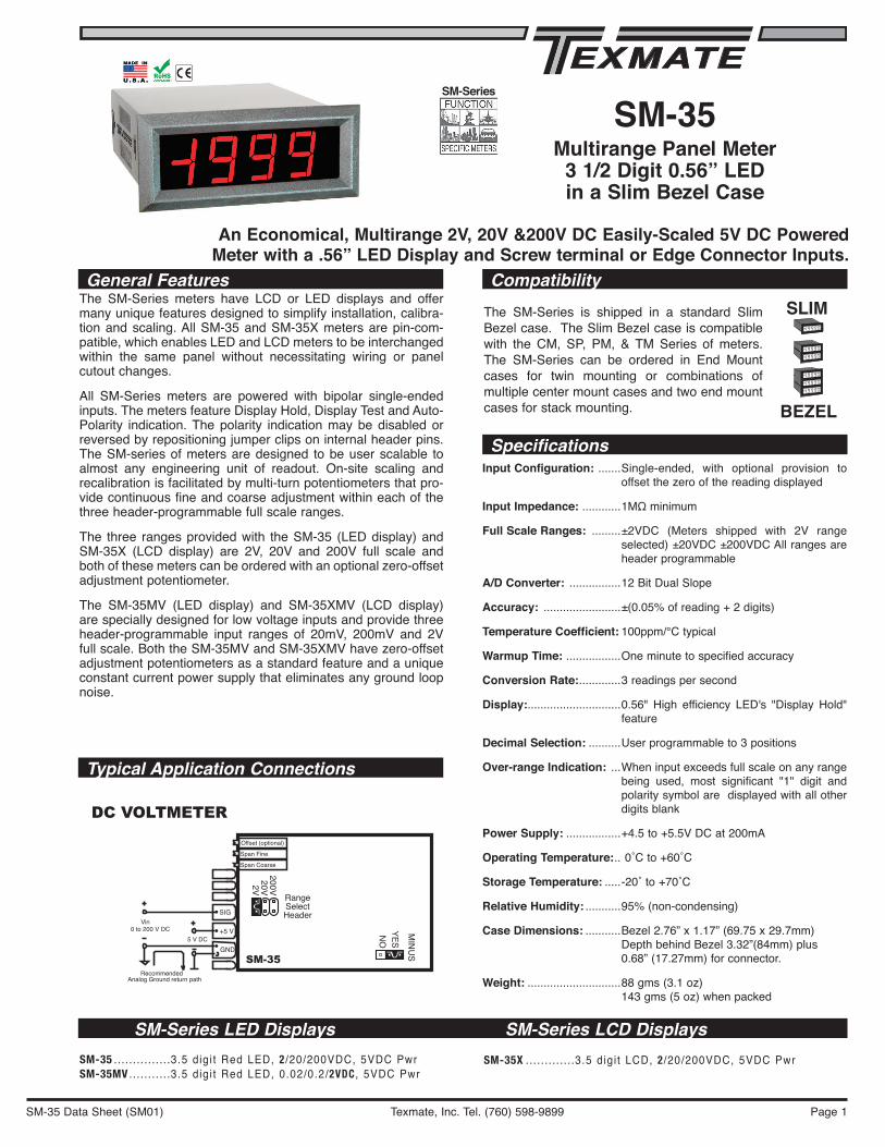
The three ranges provided with the SM-35 (LED display) and SM-35X (LCD display) are 2V, 20V and 200V full scale and both of these meters can be ordered with an optional zero-offset ad just ment potentiometer.
The SM-35MV (LED display) and SM-35XMV (LCD display) are specially designed for low voltage inputs and provide three header-programmable input ranges of 20mV, 200mV and 2V full scale. Both the SM-35MV and SM-35XMV have zero-offset ad just ment po ten ti ome ters as a standard fea ture and a unique constant current power supply that eliminates any ground loop noise.
Input Configuration: .......Single-ended, with optional provision to offset the zero of the reading displayed
Input Impedance: ............1MΩ minimum
Full Scale Ranges: .........±2VDC (Meters shipped with 2V range selected) ±20VDC ±200VDC All ranges are header programmable
A/D Converter: ................12 Bit Dual Slope
Accuracy: ........................±(0.05% of reading + 2 digits)
Temperature Coefficient: 100ppm/°C typical
Warmup Time: .................One minute to speci fied accuracy
Conversion Rate: .............3 readings per second
Display:.............................0.56" High efficiency LED's "Display Hold" feature
Decimal Selection: ..........User programmable to 3 positions
Over-range Indication: ...When input exceeds full scale on any range being used, most significant "1" digit and polarity symbol are displayed with all other digits blank
Power Supply: .................+4.5 to +5.5V DC at 200mA
Operating Temperature: .. 0˚C to +60˚C
Storage Temperature: .....-20˚ to +70˚C
Relative Humidity: ...........95% (non-condensing)
Case Dimensions: ...........Bezel 2.76” x 1.17” (69.75 x 29.7mm) Depth behind Bezel 3.32”(84mm) plus 0.68” (17.27mm) for connector.
Weight: .............................88 gms (3.1 oz)143 gms (5 oz) when packed
An Economical, Multirange 2V, 20V &200V DC Easily-Scaled 5V DC PoweredMeter with a .56” LED Display and Screw terminal or Edge Connector Inputs.
General Features
Specifications
SM-Series
SM-Series LED Displays SM-Series LCD DisplaysSM-35 ...............3.5 digi t Red LED, 2 /20/200VDC, 5VDC PwrSM-35MV ...........3.5 digi t Red LED, 0.02/0.2/2VDC , 5VDC Pwr
SM-35X .............3.5 digi t LCD, 2 /20/200VDC, 5VDC Pwr
Compatibility
Typical Application Connections
SM-35
Offset (optional)
Span Fine
Span Coarse
RangeSelectHeader
200V20V2V
SIG
+5 V
GND
Vin0 to 200 V DC
5 V DC
RecommendedAnalog Ground return path
DC VOLTMETER
MIN
US
YESN
O
SLIM
BEZEL
The SM-Series is shipped in a standard Slim Bezel case. The Slim Bezel case is compatible with the CM, SP, PM, & TM Series of meters. The SM-Series can be ordered in End Mount cases for twin mounting or combinations of multiple center mount cases and two end mount cases for stack mounting.

Texmate, Inc. Tel. (760) 598-9899SM-35 Data Sheet (SM01) Page 2
For most applications where it is not necessary to activate Display Hold, Display Test, or remotely change the selected decimal point, the three screw terminal blocks supplied with the meter can be used to connect Signal Low Input & Power Supply Ground (joined on the one terminal), Signal High Input and +5VDC Power Input. For other applications, the Texmate SM-35 interconnects by means of a stan-dard PC board edge connector having two rows of 10 pins each, spaced on 0.156" centers. Connectors are available from Texmate, or from almost any connector manufacturer.
REAR OF METER WITH PCB EDGE CONNECTOR MOUNTED(For mounting of screw terminal blocks see rear page)
Pins A, 1 and 3 - Decimal Select: Decimal points may be blanked as required by carefully scraping off the fine tracks linking these pins to Decimal Select Common using a pair of pliers or a small screwdriver blade. Re-connect either by linking the appropriate pins on the connector or by solder-bridging the junctions located on the PC board edge fingers.Pins B and 2 - Decimal Select Common: Common return pins for decimal point selection.Pins J and K - Power Supply Ground: Power supply ground return (Note: Separate connections to Pins J & K and Pins 8 & 9 are recommended when using edge connectors with the meter, to minimize ground loop effects.).Pin L - Display Hold Input (CMOS compatible): If Pin L is left
+ 5 V – 5 V
GND
Input HI
Reference
AnalogCommon
Input LO
Hold
Test
12 Bit A/D andDisplay Driver
MINUSGND
GNDCOM
1XX.X
1X.XX
COM
1.XXX
DP Common
DP Common
1XX•X DP1X•XX DP
1•XXX DP
0.56" Display
NegativeActivationHeader
680
680680
To Display
Clock
YESNO
1M1M
OptionalZero Pot
TEST
HOLD
SIG+5V
HoldTest
+5V DC
Input HI
50K
470K
SpanFine Pot
4K75
4K3
1K
1K
+5V
+1.25V
InputProtection
Circuit
48KHzClockCircuit
–5VGeneration
Circuit–5V
RangeSelectHeader
SpanCoarse
Pot
2V
0.1
20V200V
GND
+5V
Power GND
1
A
2
B
3
C
4 5 6 7 8 9 10
D E F H J K L
Offset Span Fine Span Coarse
1
A
2
B
3
C
4 5 6 7 8 9 10
D E F H J K L
Offset (Optional) Span Fine Span Coarse
1.XXX
COM
1X.XX
SIG
1XX.X
COM
N/C
+5 V
GND GND
TEST HOLD
Decimal Select - 1
Decimal Select Common - 2
Decimal Select - 3
Signal High Input4
56
7
8
9
+5 V DC PowerSupply Input
Signal Low Input
Display Test Input - 10
A - Decimal Select
B - Decimal Select Common
C - No Connection
Power Supply Ground
L - Display Hold Input
J
K
Fine "Scrape Off" Tracks Solder Junction
Functional Diagram
Connector PinoutsComponent Layout
Signal Conditioning Components
open, the meter will operate in a free-running mode. Whilst Pin L is connected to Common Pins 2 & B, the meter will latch up; A/D conversions will continue but the display will not be updat-ed until Pin L is released.Pins 4 and 5 - Signal High Input: Signal inputs for all voltage ranges are applied to these pins. Maximum overvoltage pro tec-tion is ±400V DC or 280V AC.Pins 6 and 7 - +5V DC System Power Input: The meter requires a regulated low-ripple 5V DC power supply applied to these pins.Pins 8 and 9 - Signal Low Input: Signal low input of the ana-log to digital converter circuits (Note: When measuring input signals (on the 2V range) that are not isolated from the +5V DC supply used to power the meter, a ground loop can be created that will cause the least significant digit to exhibit errors and instability. To avoid this problem, the ground return path of the analog signal should be connected to the power supply ground only at the Signal Low Input Pins 8 & 9 of the meter.).Pin 10 - Display Test Input: All numeric display segments will operate when Pin 10 is connected to Common Pins 2 & B.CAUTION: The Display Test function is only intended for momentary operation. Continuous application of Display Test will, in time, damage the display.
Zero Offset(optional) Span Fine Span Coarse
Minus Display HeaderRange Select Header
SPAN Coarse Potentiometer (Pot)The 15 turn SPAN Coarse pot is on the right side (as viewed from the back of the meter). Typical adjustment is 100% of the input signal range.
ZERO Potentiometer (Pot) OptionalThe Optional ZERO pot when installed is to the left of the SPAN pots (as viewed from the back of the meter). Typically it enables the displayed reading to be offset ±1000 counts.
SPAN Fine Potentiometer (Pot)The 15 turn SPAN Fine pot is the middle pot (as viewed from the back of the meter). Typical adjustment is 10% of the input signal range.
RANGE SELECT Header
Range values are marked on the PCB. Three positions are provided. After selecting a new range with the single jumper clip, recalibration is required.
DC mV5010020050100200
CAUTION: This meter employs high impedance CMOS inputs. Although internal protection has been provided for several hundred volt overloads, the meter will be
destroyed if subjected to the high kilovolts of static discharge that can be produced in low humidity environments. Always handle the meter with ground protection.

Texmate, Inc. Tel. (760) 598-9899SM-35 Data Sheet (SM01) Page 3
Calibration Procedure
Minus Sign Header
1) Select the F.S. input voltage range by re-positioning the jumper clip on the range select header as indicated by the voltages marked on the PCB.
2) Short Signal High Input Pins 4 & 5 to Signal Low Input Pins 8 and 9.
3) Adjust Zero Offset until the display reads zero. 4) Apply F.S. voltage.5) Adjust Span Coarse & Span Fine controls; clockwise
increases the displayed reading.6) Adjust Zero Offset to offset the zero reading as required.(Re-calibration must be performed after changing ranges)
Decimal Point SelectionThe meter is shipped from the factory with all the decimal points on. To turn off un wanted decimals, use a pair of long-nosed pliers to scrape off the fine tracks connecting decimals to decimal select common (alternatively, use a scalpel or small screwdriver). Re con nect by soldering where shown.
RE-BRIDGE HERE
PCB Edge ConnectorA standard 20-pin edge con nec tor (two rows of 10 pins on 0.156" centers) is used to connect the SM-35 meter. Order part no. CN-L10.
Optional PCB Edge Connector
Push-On Screw TerminalsThey provide the greatest convenience and ease of useTexmate’s exclusive optional Push-On Connectors combine an edge card connector and a 10 position screw terminal block. Push-On Connectors are ordered preconfigured for each specific power supply voltage and each optional power supply available for the SM-Series.
Part Number: CN-PUSH/SM
TB-Kit Screw ConnectorsTexmate’s individual screw ter-mi nal blocks offer a convenient al ter na tive to edge connectors for many ap pli ca tions, allowing com-plete in stal la tion, con figu ra tion and calibration with out the need for soldering.Slide each terminal block over the
PCB until the hole aligns. Insert the re tain ing screw to secure.Each kit includes: 3 plastic blocks with metal contacts, 4 screws with spade connectors, 1 metal contact and 3 quick disconnects.
TB-KITincluded
Activates Minus sign on display
YESNO
Disable Minus sign on display
YESNO
Minus Sign HeaderThis header allows the Minus Sign to work normally.
Meters that also use Slim Bezel Case Enclosure
CM-35XTL ...... Less than 1V DC loop drop and 1 Joule energy storageCM-35XT ....... Economical 4-20mA loop-powered meter
SP-35X .......... Signal Power DC voltage measurement from 5.0V DC to 199.9V DC
PM-45X ......... 4.5 digit 0.48” LCD DPMPM-45XU ....... Lower cost version of PM-45XPM-45L ......... 4.5 digit 0.4” LED DPMPM-45LU........ Lower cost version of PM-45L
CAUTION - ELECTRICAL SHOCK HAZARD All internal parts of the meter may be at the same electrical potential as the input signal and power supply. Do not reposition the signal conditioning
components when input voltages are applied. When measuring dan-gerously high input voltages, extreme care must be taken to insulate the connector pins as well as all metal parts of the meter. A suitable high voltage warning notice should be affixed to those meters where there is any possibility that the meter could be removed from its case, or the internal components accessed, concurrent with the existence of a high voltage input signal.
!
PS-505 . . . . . . . 5V DC Regulated Power Supply, 0.5A OutputPS-510 . . . . . . . 5V DC Regulated Power Supply, 1A Output
AM-20 ........... 20 segment LED bargraph, 5V DC power
TB-KITNOT Included
Order Part #: TB-KIT

Texmate, Inc. Tel. (760) 598-9899SM-35 Data Sheet (SM01) Page 4
SM Case Dimensions and Panel Cutouts
Ordering InformationStandard Options for this Model Number
Part Number Description ListBASIC MODEL NUMBER Includes plug in type screw terminals, stan-
dard display and standard power supply unless optional versions are ordered.SM-35 ................ 3.5 digit Red LED, 2/20/200VDC, 5VDC Pwr . . . .$59
DISPLAySTANDARD ......... Red LED, 0.96 inch high. . . . . . . . . . . . . . . . . . . . . N/CSM-GREEN . . . Green LEDs, for SM-35/35MV only . . . . . . . . . . $12Special Options and Accessories
Part Number Description ListSPECIAL OPTIONS (Specify Inputs & Req. Reading)
HD-CHANGE. . . . Range change from the std. input as shown in BOLD type . . . . $8
V0-50K . . . . . . . Zero offset potentiometer 50k. . . . . . . . . . . . . . . $7CB-FS35. . . . . . Non-Std Range and Scale Changes . . . . . . . . . . . $12 SM-FSCL . . . . . SM-35 4 to 20mA Factory Scaling . . . . . . . . . . . $20
ACCESSORIES CN-L10 . . . . . . . Edge Connector with Solder eyelet, 10 Pin Dual $4CN-PUSH/SM. . Push-0n Screw Terminal Block Connector . . . . . $20TB-KIT. . . . . . . . . . Terminal Block Connector Kit (3) . . . . . . . . . . . . . . .$2SL.CASECLR . . Slim Bezel Case, Clear Faceplate w/Mtg Hrdwre $9 SL.CASERED. . Slim Bezel Case, Red Faceplate w/Mtg Hrdwre $9 CM.CASECLR . Ctr. Mount Case, Clear Faceplate w/Mtg Hardware $10CM.CASERED . Ctr. Mount Case, Red Faceplate w/Mtg Hardware $10 EM.CASECLR . End Mount Case, Clear Faceplate w/Mtg Hrdwre $10 EM.CASERED . End Mount Case, Red Faceplate w/Mtg Hardware $10PS-505 . . . . . . . 5V DC Regulated Power Supply, 0.5A Output . . $25PS-510 . . . . . . . 5V DC Regulated Power Supply, 1A Output . . . $30Prices subject to change without notice.
OPTIONAL TWIN MOUNTING OR MUL TIPLE ARRAy CASES
4"(101.6mm)
2.52"(64.2mm)
0.68"(17.22mm)
3.32"(84mm)
0.96"(24.4mm)
0.304"(7.72mm)
0.19"(4.88mm)
1.17"(29.7mm)
2.26"(57.4mm)
2.76"(69.75mm)
0.58"(14.71mm) 0.95"
(24.23mm)
2.55"(64.8mm)
0.97"(24.6mm) Front Panel Cutout
The Slim Bezel Case is supplied as standard. If specified at time of ordering, any combination of Twin Mounting and Multiple Array Cases may be substituted at no additional cost. Extra cases may be ordered separately.
Insert DPM through cutout hole from front of panel. Attach mounting brackets and screws as shown, using second slot when panel thick-ness is greater than 1/4 inch. Tighten screws against rear of panel.
CENTER MOUNT CASEAny number of Center Mount cases may be fitted between two End Mount cases for multiple arrays.Part No. CM-CASERED for LED's CM-CASECLR for LCD's
SLIM BEZEL CASEStandard Black ABS case with matte finish bezel for single unit mounting.Part No. SL-CASERED for LED's SL-CASECLR for LCD's
END MOUNT CASESame styling as Slim Bezel case but with bottom edge of bezel removed. Two End Mount cases can be twin mounted in a single cutout.Part No. EM-CASERED for LED's EM-CASECLR for LCD's
1.17"(29.7mm)
1.07"�(27mm)
slim bezel end mount - DS
0.97"�(24.5mm)
slim bezel center mount -DS
STANDARD SLIM BEZEL CASE
WARRANTYTexmate warrants that its products are free from defects in material and workmanship under normal use and service for a period of one year from date of shipment. Texmate’s obligations under this warranty are limited to replacement or repair, at its option, at its factory, of any of the products which shall, within the applicable period after shipment, be returned to Texmate’s facility, transportation charges pre-paid, and which are, after examination, disclosed to the sat-isfaction of Texmate to be thus defective. The warranty shall not apply to any equipment which shall have been repaired or altered, except by Texmate, or which shall have been subjected to misuse, negligence, or accident. In no case shall Texmate’s liability exceed the original pur-chase price. The aforementioned provisions do not extend the original warranty period of any product which has been either repaired or replaced by Texmate.
USER’S RESPONSIBILITYWe are pleased to offer suggestions on the use of our various products either by way of printed matter or through direct contact with our sales/application engineering staff. However, since we have no control over the use of our products once they are shipped, NO WARRANTY WHETHER OF MERCHANTABILITY, FITNESS FOR PURPOSE, OR OTHERWISE is made beyond the repair, replacement, or refund of purchase price at the sole discretion of Texmate. Users shall determine the suitability of the product for the intended application before using, and the users assume all risk and liability whatsoever in connection therewith, regardless of any of our suggestions or statements as to application or construction. In no event shall Texmate’s liability, in law or otherwise, be in excess of the purchase price of the product.
Texmate cannot assume responsibility for any circuitry described. No circuit patent or software licenses are implied. Texmate reserves the right to change circuitry, operating software, speci-fications, and prices without notice at any time.
For product details visit www.texmate.comLocal Distributor Address
450 State Place • Escondido, CA 92029Tel: 1-760-598-9899 • USA 1-800-839-6283 • That’s 1-800-TEXMATEFax: 1-760-598-9828 • Email: [email protected] • Web: www.texmate.com
Copyright © 2017 Texmate Inc. All Right Reserved.