high accuracy legendary reliability fast delivery friendly ...panelmeters.weschler.com/asset/texmate...
TRANSCRIPT

(Z660)www.texmate.com
HIGH ACCURACYLEGENDARY RELIABILITY
FAST DELIVERYFRIENDLY APPLICATION SUPPORT
POWER TRANSDUCERS
phone: 800-903-9870 440-378-6580 fax: 800-903-9590 440-238-0660
www.weschler.com [email protected]
WESCHLER INSTRUMENTSAuthorized Distributor:

(Z660)www.texmate.com 2
Contents
AC CURRENT TRANSDUCERS Single Phase........................................................3
AC CURRENT TRANSDUCERS Three Phase. .......................................................6 AC VOLTAGE TRANSDUCERS Single Phase. .......................................................9 AC VOLTAGE TRANSDUCERS Three Phase. ......................................................12 Watts TRANSDUCERS Single Phase . ..................................................................15 Watts TRANSDUCERS Single Phase. ...................................................................18
Watts TRANSDUCERS Three Phase.....................................................................19
VARs TRANSDUCERS Single Phase . ..................................................................23
VARs TRANSDUCERS Three Phase . ...................................................................27
Watts + VARs TRANSDUCERS Single Phase . ....................................................31
Watts + VARs TRANSDUCERS Three Phase ......................................................35
Watt Hours TRANSDUCERS Single Phase . ........................................................39
Watt Hours TRANSDUCERS Three Phase . .........................................................43
Watt+Watt Hours TRANSDUCERS Single Phase . ..............................................47
Watt+Watt Hours TRANSDUCERS Single Phase . ..............................................50
Watt + Watt Hours TRANSDUCERS Three Phase . ............................................51
VAR Hours TRANSDUCERS Single Phase . .........................................................56
VAR Hours TRANSDUCERS Three Phase ...........................................................59
VAR Hours TRANSDUCERS Three Phase ...........................................................62
VARs+VAR Hours TRANSDUCERS Single Phase . .............................................63
VARs+VAR Hours TRANSDUCERS Three Phase . ..............................................67
AC Power Factor TRANSDUCERS Single Phase . ..............................................71
AC Power Factor TRANSDUCERS Three Phase . ............................................... 74
FREQUENCY TRANSDUCERS . .............................................................................77
CASE DIMENSIONS - CASE A & C. ......................................................................80
CASE DIMENSIONS - CASE B & D. ......................................................................81

(Z660)www.texmate.com 3
MODELS OFFERED
FEATURES
AC CURRENT TRANSDUCERS Single Phase
TA-1 base model Average sensing
TA-1T base model True rms sensing
• True RMS sensing is recommended for input signals with distortion.
• Direct connect to the transducer for inputs ≤ 5A AC.
• Connect using a current Transformer (C.T.) for inputs greater than 5A AC.
• High accuracy ±0.2% of Rated Output (R.O.)• Super high accuracy ±0.1% of Rated Output (R.O.) available as a special order.*• High immunity to external noise.• Quick and easy mounting to 35mm DIN Rail (DIN46277)
GENERAL SPECIFICATIONS
Accuracy ............................. ± 0.2% R.O. Standard for 10 to 100% of rated output ± 0.1% R.O. (Special Option)
Temp. coefficient ................ ≤100ppm/ºC of span ≤60ppm/ºC for ambient temperature of 25ºC ±10ºC
Temp. range ........................ Storage temperature range -20ºC to 60ºC (4ºF to 140ºF) Operating temperature range 0ºC to 50ºC (32ºF to 122ºF)
Humidity range ................... Up to 95% RH non condensing
Isolation ............................... Between Input/Output/Power/Case
Dielectric test ...................... DIN-IEC 688 2K Vrms/1 min, Between terminal to terminal 2.8K Vrms/1 min, Between terminal to terminal
Surge test ............................ DIN-IEC 255-4, ANSI C37 90a/1974 5KV(1.2x50 µs)
Insulation Resistance ........ Greater than 100 M Ω at 500V DC
Housing material ................ ABS Resin(94V-0) or metal
Mounting ............................. Screw mount metal case or Plastic DIN Rail 35mm
Auxiliary Power................... AC 115/230V ± 15%, 50/60Hz, 3VA DC 24V ± 20%(optional) 110V DC ± 20%(optional)

(Z660)www.texmate.com 4
AC CURRENT TRANSDUCERS Single Phase
1 2 3 4
5 6 7 8
OUTPUT INPUT
POWER
+
230 V115 V
LineNeutral
OUTPUT+
INPUT SPECIFICATIONS
AC Input .............................. 0 to 1Amps AC, 0 to 5Amps AC or custom input
Frequency ........................... 45Hz to 65Hz, 400Hz
Burden ................................. ≤0.2VA
Response Sensitivity ......... ≤0.5% of measuring range to maximum input range
Input Overload Capacity .... 3 times the rated input current continuously. 10 times the rated current for 10 seconds. 50 times the rated input current for 1 second. 80 times the rated input current for 0.5 second.
OUTPUT SPECIFICATIONS
Output Variables ................ DC mA or DC Volts
Ripple....................................< 0.5% of rated output. Peak to Peak (maximum)
Response Time ....................< 400 milliseconds to go from 0 to 99% of output
Zero Adjustment ..................± 5% of rated output (minimum)
Span Adjustment .................± 10% of rated output (minimum)
Load Resistance ................. 10K Ω maximum for 0 to 1mA output 500 Ω maximum for 4 to 20mA output 500 Ω minimum for 0 to 10V output
CONNECTION DIAGRAM
TA-1TA-1T

(Z660)www.texmate.com 5
AC CURRENT TRANSDUCERS Single Phase
Example:Product Ordering Code of TA-1T21212
TA-1T: Single Phase, True RMS sensing, AC Current transducer2: 0 to 1 Amps AC input1: 45Hz to 65Hz2: 4 to 20 mA output1: 115VAC or 230VAC power2: Metal Case
ORDERING INFORMATION
Single Phase. Average sensing.
45Hz to 65Hz
0 to 5A AC input
0 to 1A AC inputCustom Input Range
(Max 10A AC)
115V AC / 230V AC Power
24V DC Power
125 V DC Power
Custom Power
Plastic Case DIN Rail mountCase C
Metal Case Screw mountCase A
Single Phase. True RMS sensing.
400Hz
TA-1T
2
TA-1
1
Y
21
Y
3
2
1
3
Y
2
1
BASE UNIT INPUT OUTPUT POWER MOUNTING
2
1
FREQUENCY
0 to 1mA DC output
4 to 20mA DC output
0 to 10V DC output
Custom output Range(Max 20mA DC or 10V DC)

(Z660)www.texmate.com 6
MODELS OFFERED
FEATURES
AC CURRENT TRANSDUCERS Three Phase
TA-3 base model Average sensing
TA-3T base model True rms sensing
• True RMS sensing is recommended for input signals with distortion.
• Direct connect to the transducer for inputs ≤ 5A AC.
• Connect using a Potential Transformer (C.T.) for inputs > 5A AC.
• High accuracy ±0.2% of Rated Output (R.O.)• Super high accuracy ±0.1% of Rated Output (R.O.) available as a special order.*• High immunity to external noise.• Quick and easy mounting to 35mm DIN Rail (DIN46277)• Many input and output combinations
GENERAL SPECIFICATIONS
Accuracy ............................. ± 0.2% R.O. Standard for 10 to 100% of rated output ± 0.1% R.O. (Special Option)
Temp. coefficient ................ ≤100ppm/ºC of span ≤60ppm/ºC for ambient temperature of 25ºC ±10ºC
Temp. range ........................ Operation temperature range -20ºC to 60ºC
Humidity range ................... Up to 95% RH non condensing.
Isolation ............................... Between Input/Output/Power/Case
Dielectric test ...................... DIN-IEC 688 2K Vrms/1 min, Between terminal to terminal 2.8K Vrms/1 min, Between terminal to terminal
Surge test ............................ DIN-IEC 255-4, ANSI C37 90a/1974 5KV(1.2x50 µs)
Insulation Resistance ........ Greater than 100 M Ω at 500V DC
Housing material ................ ABS Resin (94V-0) or metal
Mounting ............................. Screw mount metal case or Plastic DIN Rail 35mm
Auxiliary Power................... AC 115/230V ± 15%, 50/60Hz, 3VA DC 24V ± 20%(optional) 125V DC ± 20%(optional)

(Z660)www.texmate.com 7
AC CURRENT TRANSDUCERS Three Phase
A INPUT B INPUT C INPUT
+OUTPUT
BOUTPUT
A +OUTPUT
C+
+ + +
ACPOWER230 V
115 V
L2L1
L3
1 2 3 4 5 6 7 8 9
10 11 12 13 14 15 16 17 18
INPUT SPECIFICATIONS
AC Input ............................... 0 to 5A AC, 0 to 1A AC, custom input (10A AC maximum)
Frequency ........................... 45Hz to 65Hz
Burden ................................. ≤0.2VA
Response Sensitivity ......... ≤0.5% of measuring range to maximum input range
Input Overload Capacity .... 3 times the rated input current continuously. 10 times the rated input current for 10 secs. 50 times the rated input current for 1 sec. 80 times the rated input current for 0.5 secs
OUTPUT SPECIFICATIONS
Output Variables ................. DC mA or DC Volts
Ripple ................................... < 0.5% of rated output. Peak to Peak (maximum)
Response Time ................... < 400 milliseconds to go from 0 to 99% of output
Zero Adjustment ................. ± 5% of rated output (minimum)
Span Adjustment ................ ± 10% of rated output (minimum)
Load Resistance ................. 10 kΩ maximum for 0 to 1mA output 500 Ω maximum for 4 to 20mA output 500 Ω minimum for 0 to 10V output
CONNECTION DIAGRAM

(Z660)www.texmate.com 8
Example:Product Ordering Code of TA-3T21212
TA-3T: 3 Phase, True RMS sensing, AC Current transducer2: 0 to 1 Amps AC input1: 45Hz to 65Hz2: 4 to 20 output1: 115VAC or 230VAC power2: Metal Case
ORDERING INFORMATION
Three Phase. Average sensing.
45Hz to 65Hz
0 to 5A AC input
0 to 1A AC inputCustom Input Range
(Max 10A AC)
115V AC / 230V AC Power
24V DC Power
125 V DC Power
Custom Power
Plastic Case DIN Rail mountCase D
Metal Case Screw mountCase B
Three Phase. True RMS sensing.
400Hz
TA-3T
2
TA-3
1
Y
21
Y
3
2
1
3
Y
2
1
BASE UNIT INPUT OUTPUT POWER MOUNTING
2
1
FREQUENCY
AC CURRENT TRANSDUCERS Three Phase
0 to 1mA DC output
4 to 20mA DC output
0 to 10V DC output
Custom output Range(Max 20mA DC or 10V DC)

(Z660)www.texmate.com 9
MODELS OFFERED
FEATURES
AC VOLTAGE TRANSDUCERS Single Phase
• True RMS sensing is recommended for input signals with distortion.
• Direct connect to the transducer for inputs ≤ 600V AC.
• Connect using a Potential Transformer (P.T.) for inputs greater than 600V AC.
• High accuracy ±0.2% of Rated Output (R.O.)• Super high accuracy ±0.1% of Rated Output (R.O.) available as a special order.*• High immunity to external noise.• Quick and easy mounting to 35mm DIN Rail (DIN46277)• Many input and output combinations
GENERAL SPECIFICATIONS
Accuracy ............................. ± 0.2% R.O. Standard for 10 to 100% of rated output ± 0.1% R.O. (Special Option)
Temp. coefficient ................ ≤100ppm/ºC of span ≤60ppm/ºC for ambient temperature of 25ºC ±10ºC
Temp. range ........................ Operating temperature range -20ºC to 60ºC
Humidity range ................... Up to 95% RH non condensing.
Isolation ............................... Between Input/Output/Power/Case
Dielectric test ...................... DIN-IEC 688 2K Vrms/1 min, Between terminal to terminal 2.8K Vrms/1 min, Between terminal to terminal
Surge test ............................ DIN-IEC 255-4, ANSI C37 90a/1974 5KV(1.2x50 µs)
Insulation Resistance ........ Greater than 100 M Ω at 500V DC
Housing material ................ ABS Resin(94V-0) or metal
Mounting ............................. Screw mount metal case or Plastic DIN Rail 35mm
Auxiliary Power................... AC 115/230V ± 15%, 50/60Hz, 3VA DC 24V ± 20%(optional) 125V DC ± 20%(optional)
TV-1 base model Average sensing
TV-1T base model True rms sensing

(Z660)www.texmate.com 10
AC VOLTAGE TRANSDUCERS Single Phase
INPUT SPECIFICATIONSAC Input ............................... 0 to 150V AC, 0 to 300V AC, 0 to 600V AC or custom input
Frequency ........................... 45Hz to 65Hz
Burden ................................. ≤0.1VA
Response Sensitivity ......... ≤0.5% of measuring range to mazimum input range
Input Overload Capacity .... 1.25 times the rated input current continuously. 2 times the rated current for 10 seconds. 4 times the rated input current for 5 seconds. Or 600V AC rms continuous.
OUTPUT SPECIFICATIONS
Output Variables ................. DC mA or DC Volts
Ripple ................................... < 0.5% of rated output. Peak to Peak (maximum)
Response Time ................... < 400 milliseconds to go from 0 to 99% of output
Zero Adjustment ................. ± 5% of rated output minimum
Span Adjustment ................ ± 10% of rated output minimum
Load Resistance ................. 10K Ω maximum for 0 to 1mA output 500 Ω maximum for 4 to 20mA output 500 Ω minimum for 0 to 10V output
CONNECTION DIAGRAM
TV-1TV-1T
1 2 3 4
5 6 7 8
OUTPUT INPUT
POWER
+
230 V115 V
LineNeutralOUTPUT+

(Z660)www.texmate.com 11
Example:Product Ordering Code of TV-1T12312
TV-1T: Single Phase, True RMS sensing, AC Voltage transducer1: 0 to 150V AC input2: 400Hz3: 0 to 10V DC output1: 115VAC or 230VAC power2: Metal Case
ORDERING INFORMATION
AC VOLTAGE TRANSDUCERS Single Phase
Single Phase. Average sensing.
45Hz to 65Hz
0 to 150V AV input
0 to 300V AC input
Custom Input Range(600 V AC Max)
0 to 600V AC input
115V AC / 230V AC Power
24V DC Power
125 V DC Power
Custom Power
Plastic Case DIN Rail mountCase C
Metal Case Screw mountCase A
Single Phase. True RMS sensing.
400Hz
TV-1T
2
TV-1
1
Y321
Y321
3
Y
2
1
BASE UNIT INPUT OUTPUT POWER MOUNTING
2
1
FREQUENCY
0 to 1mA DC output
4 to 20mA DC output
0 to 10V DC output
Custom output Range(Max 20mA DC or 10V DC)

(Z660)www.texmate.com 12
AC VOLTAGE TRANSDUCERS Three Phase
MODELS OFFERED
FEATURES
TV-3 base model Average sensing
TV-3T base model True rms sensing
• True RMS sensing is recommended for input signals with distortion.
• Direct connect to the transducer for inputs ≤ 600V AC.
• Connect using a Potential Transformer (P.T.) for inputs > 600V AC.
• High accuracy ±0.2% of Rated Output (R.O.)• Super high accuracy ±0.1% of Rated Output (R.O.) available as a special order.*• High immunity to external noise.• Quick and easy mounting to 35mm DIN Rail (DIN46277)• Many input and output combinations.
GENERAL SPECIFICATIONS
Accuracy ............................. ± 0.2% R.O. Standard for 10 to 100% of rated output ± 0.1% R.O. (Special Option)
Temp. coefficient ................ ≤100ppm/ºC of span ≤60ppm/ºC for ambient temperature of 25ºC ±10ºC
Temp. range ........................ Operation temperature range -20ºC to 60ºC
Humidity range ................... Up to 95% RH non condensing.
Isolation ............................... Between Input/Output/Power/Case
Dielectric test ...................... DIN-IEC 688 2K Vrms/1 min, Between terminal to terminal 2.8K Vrms/1 min, Between terminal to terminal
Surge test ............................ DIN-IEC 255-4, ANSI C37 90a/1974 5KV(1.2x50 µs)
Insulation Resistance ........ Greater than 100 M Ω at 500V DC
Housing material ................ ABS Resin(94V-0) or metal
Mounting ............................. Screw mount metal case or Plastic DIN Rail 35mm
Auxiliary Power................... AC 115/230V ± 15%, 50/60Hz, 3VA DC 24V ± 20%(optional) 125V DC ± 20%(optional)

(Z660)www.texmate.com 13
AC VOLTAGE TRANSDUCERS Three Phase
INPUT SPECIFICATIONSAC Input ............................... 0 to 150V AC, 0 to 300V AC, 0 to 600V AC or custom input
Frequency ........................... 45Hz to 65Hz
Burden ................................. ≤0.1VA
Response Sensitivity ......... ≤0.5% of measuring range to maximum input range
Input Overload Capacity .... 600V AC rms continuous 1.25 times the rated input Voltage continuously. 2 times the rated input Voltage for 10 secs. 4 times the rated input Voltage for 5 secs.
OUTPUT SPECIFICATIONS
Output Variables ................. DC mA or DC Volts
Ripple ................................... < 0.5% of rated output. Peak to Peak (maximum)
Response Time ................... < 400 milliseconds to go from 0 to 99% of output
Zero Adjustment ................. ± 5% of rated output (minimum)
Span Adjustment ................ ± 10% of rated output (minimum)
Load Resistance ................. 10 kΩ maximum for 0 to 1mA output 500 Ω maximum for 4 to 20mA output 500 Ω minimum for 0 to 10V output
CONNECTION DIAGRAM
TV-1TVT-1
1S 1L 3S 3L
+OUTPUT
AOUTPUT
C+
+ +
ACPOWER230 V
115 V
L2L3
L1
1 2 3 4 5 6 7 8 9
10 11 12 13 14 15 16 17 18
1S 1L 2S 2L 3S 3L
+OUTPUT
BOUTPUT
A +OUTPUT
C+
+ + +
ACPOWER230 V
115 V
L3N
L2L1
P.T.1 P.T.2 P.T.3
1 2 3 4 5 6 7 8 9
10 11 12 13 14 15 16 17 18
Three Phase 3 wire Three Phase 4 wire

(Z660)www.texmate.com 14
AC VOLTAGE TRANSDUCERS Three Phase
Example:Product Ordering Code of TV-3T12312
TV-3T: Three Phase, True RMS sensing, AC Voltage transducer1: 0 to 150V AC input2: 400Hz3: 0 to 10V DC output1: 115VAC or 230VAC power2: Metal Case
ORDERING INFORMATION
Three Phase. Average sensing.
45Hz to 65Hz
0 to 150V AV input
0 to 300V AC input
Custom Input Range(600V AC Max)
0 to 600V AC input
115V AC / 230V AC Power
24V DC Power
125 V DC Power
Custom Power
Plastic Case DIN Rail mount Case D
Metal Case Screw mountCase B
Three Phase. True RMS sensing.
400Hz
TV-3T
2
TV-3
1
Y321
Y321
3
Y
2
1
BASE UNIT INPUT OUTPUT POWER MOUNTING
2
1
FREQUENCY
0 to 1mA DC output
4 to 20mA DC output
0 to 10V DC output
Custom output Range(Max 20mA DC or 10V DC)

(Z660)www.texmate.com 15
MODELS OFFERED
FEATURES
Watts TRANSDUCERS Single Phase
TW-12 base model Single Phase, 2 Wire – 1 Element
TW-13 base model Single Phase, 3 Wire – 2 Element
• Accurate measurement of the active power Watts for balanced or unbalanced loads.
• The output signals are isolated load independent DC mA or DC Volts, representing the measured value of the active power Watts.
• Uses Time Division Multiplication (TDM) for precision measurement of even distorted signals.• High accuracy ±0.2% of Rated Output (R.O.)• Super high accuracy ±0.1% of Rated Output (R.O.) available as a special order.*• High immunity to external noise.• Quick and easy mounting to 35mm DIN Rail (DIN46277) or screw mounting.• Many input and output signal combinations
GENERAL SPECIFICATIONS
Accuracy ............................. ± 0.2% R.O. Standard for 10 to 100% of rated output ± 0.1% R.O. (Special Option)
Temp. coefficient ................ ≤100ppm/ºC of span ≤60ppm/ºC for ambient temperature of 25ºC ±10ºC
Temp. range ........................ Storage temperature range -20ºC to 60ºC Operating temperature range 0ºC to 50ºC (32ºF to 122ºF)
Humidity range ................... Up to 95% RH non condensing.
Isolation ............................... Between Input / Output / Power / Case
Dielectric Test ..................... DIN-IEC 688 2K Vrms/1 min, Between terminal to terminal 2.8K Vrms/1 min, Between terminal to terminal
Surge test ............................ DIN-IEC 255-4, ANSI C37 90a/1974 5KV(1.2x50 µs)
Insulation Resistance ........ Greater than 100 M Ω at 500V DC
Housing material ................ ABS Resin (94V-0) or metal steel sheet.
Mounting ............................. Screw mount metal case or Plastic DIN Rail 35mm
Auxiliary Power................... AC 115/230V ± 15%, 50/60Hz, 3VA DC 24V ± 20%(optional) 125V DC ± 20%(optional)

(Z660)www.texmate.com 16
INPUT SPECIFICATIONSAC Input ............................... 120V / 5A AC, 240V /5A AC for 1 phase/2 Wire
240V/120V, 5A AC for 1 phase/3 Wire custom input (600V max /10A AC max)
Frequency ........................... 60Hz ±3Hz, 50Hz ±3Hz, 400Hz ±3Hz
Burden ................................. ≤0.2VA per current circuit, ≤0.1VA per voltage circuit.
Response Sensitivity ......... ≤0.5% of measuring range to maximum input range
Input Voltage ....................... 600V AC rms continuous Overload Capacity 1.25 times the rated input Voltage continuously. 2 times the rated input Voltage for 10 secs. 4 times the rated input Voltage for 5 secs.
Input Current ....................... 3 times the rated input current continuously. Overload Capacity 10 times the rated input current for 10 secs. 50 times the rated input current for 1 sec. 80 times the rated input current for 0.5 secs
OUTPUT SPECIFICATIONS
Output Variables ................. DC mA or DC Volts
Ripple ................................... < 0.5% of rated output. Peak to Peak (maximum)
Response Time ................... < 400 milliseconds to go from 0 to 99% of output
Zero Adjustment ................. ± 5% of rated output (minimum)
Span Adjustment ................ ± 10% of rated output (minimum)
Load Resistance ................. 10 kΩ maximum for 0 to 1mA output 500 Ω maximum for 4 to 20mA output 500 Ω minimum for 0 to 10V output
Model Voltage Current Nominal WattsTW-12 1 ø / 2 Wire 120V AC (110V) 5A AC 500
TW-12 1 ø / 2 Wire 240V AC (220V) 5A AC 1000
TW-13 1 ø / 3 Wire 240V/120V AC (220V/110V)Phase volts/Line Volts
5A AC 1000
Maximum Input range value = (CT Ratio) X (PT Ratio) X (Nominal Watts)
If CT = 200A:5A PT is 3300V:110V Nominal Watts = 500 then CT Ratio = 40 then PT Ratio = 30 and Maximum input range value = 40 x 30 x 500 = 600KW
Watts TRANSDUCERS Single Phase

(Z660)www.texmate.com 17
Watts TRANSDUCERS Single Phase
CONNECTION DIAGRAM
+OUTPUT
OUTPUT+
ACPOWER230 V
115 V
LC.T.1
P.T.1
N
1S 1L
P1 P21 2 3 4 5 6 7 8 9
10 11 12 13 14 15 16 17 18
+OUTPUT
OUTPUT+
ACPOWER230 V
115 V
L1 C.T.1
P0 P2P1
1S 1L 3S 3L
C.T.3
P.T.1 P.T.2
L2
N
1 2 3 4 5 6 7 8 9
10 11 12 13 14 15 16 17 18
TW-12
TW-13

(Z660)www.texmate.com 18
Example:Product Ordering Code of TW-1212121
TW-12: Single Phase / 2Wire, 1 element AC WATTS Transducer1: 120 V and 5A AC Input2: 50Hz ± 3Hz1: 0 to 1mA DC Output2: 24V DC Power1: Plastic Case
ORDERING INFORMATION
1 Phase/ 2 Wire, 1 element
60Hz ± 3Hz
120 V and 5A AC
240 V and 5A ACCustom Input Range
(600V AC, 10Amps Max)
115V AC / 230V AC Power
24V DC Power
125 V DC Power
Custom Power
Plastic Case C. DIN Rail mount Case D
Metal Case A. Screw mountCase B
1 Phase/ 3 Wire, 2 element
50Hz ± 3Hz
Custom 400Hz ± 3Hz
TW-13
2Y
TW-12
1
Y21
Y321
3
Y
2
1
BASE UNIT INPUT OUTPUT POWER MOUNTING
2
1
FREQUENCY
0 to 1mA DC output
4 to 20mA DC output
0 to 10V DC output
Custom output Range(Max 20mA DC or 10V DC)
Watts TRANSDUCERS Single Phase

(Z660)www.texmate.com 19
Watts TRANSDUCERS Three Phase
MODELS OFFERED
FEATURES
TW-33 base model 3 Phase, 3 Wire – 2 Element
TW-34 base model 3 Phase, 4 Wire – 3 Element
• Accurate measurement of the active power Watts for balanced or unbalanced loads.
• The output signals are isolated load independent DC mA or DC Volts, representing the measured value of the active power Watts.
• Uses Time Division Multiplication (TDM) for precision measurement of even distorted signals.• High accuracy ±0.2% of Rated Output (R.O.)• Super high accuracy ±0.1% of Rated Output (R.O.) available as a special order.*• High immunity to external noise.• Quick and easy mounting to 35mm DIN Rail (DIN46277) or screw mounting.• Many input and output signal combinations
GENERAL SPECIFICATIONS
Accuracy ............................. ± 0.2% R.O. Standard for 10 to 100% of rated output ± 0.1% R.O. (Special Option)
Temp. coefficient ................ ≤100ppm/ºC of span ≤60ppm/ºC for ambient temperature of 25ºC ±10ºC
Temp. range ........................ Storage temperature range -20ºC to 60ºC Operating temperature range 0ºC to 50ºC (32ºF to 122ºF)
Humidity range ................... Up to 95% RH non condensing.
Isolation ............................... Between Input / Output / Power / Case
Dielectric Test ..................... DIN-IEC 688 2K Vrms/1 min, Between terminal to terminal 2.8K Vrms/1 min, Between terminal to terminal
Surge test ............................ DIN-IEC 255-4, ANSI C37 90a/1974 5KV(1.2x50 µs)
Insulation Resistance ........ Greater than 100 M Ω at 500V DC
Housing material ................ ABS Resin (94V-0) or metal steel sheet.
Mounting ............................. Screw mount metal case or Plastic DIN Rail 35mm
Auxiliary Power................... AC 115/230V ± 15%, 50/60Hz, 3VA DC 24V ± 20%(optional) 125V DC ± 20%(optional)

(Z660)www.texmate.com 20
Watts TRANSDUCERS Three Phase
INPUT SPECIFICATIONSAC Input ............................... 120V / 5A AC, 240V /5A AC for 3 phase/3 Wire
208V/120V & 5A AC, 416V/240V & 5A AC, for 3 Phase / 4 Wire custom input (600V max /10A AC max)
Frequency ........................... 60Hz ±3Hz, 50Hz ±3Hz, 400Hz ±3Hz
Burden ................................. ≤0.2VA per current circuit, ≤0.1VA per voltage circuit.
Response Sensitivity ......... ≤0.5% of measuring range to maximum input range
Input Voltage ....................... 600V AC rms continuous Overload Capacity 1.25 times the rated input Voltage continuously. 2 times the rated input Voltage for 10 secs. 4 times the rated input Voltage for 5 secs.
Input Current ....................... 3 times the rated input current continuously. Overload Capacity 10 times the rated input current for 10 secs. 50 times the rated input current for 1 sec. 80 times the rated input current for 0.5 secs
OUTPUT SPECIFICATIONS
Output Variables ................. DC mA or DC Volts
Ripple ................................... < 0.5% of rated output. Peak to Peak (maximum)
Response Time ................... < 400 milliseconds to go from 0 to 99% of output
Zero Adjustment ................. ± 5% of rated output (minimum)
Span Adjustment ................ ± 10% of rated output (minimum)
Load Resistance ................. 10 kΩ maximum for 0 to 1mA output 500 Ω maximum for 4 to 20mA output 500 Ω minimum for 0 to 10V output
Model Voltage Current Nominal WattsTW-33 3 ø / 3 Wire 120V AC (110V) 5A AC 1000
TW-33 3 ø / 3 Wire 240V AC (220V) 5A AC 2000
TW-34 3 ø / 4 Wire 208V/120V AC (190V/110V)phase volts / line volts
5A AC 1500
TW-34 3 ø / 4 Wire 416V/240V AC (380V/220V)phase volts / line volts
5A AC 3000
Maximum Input range value = (CT Ratio) X (PT Ratio) X (Nominal Watts)If CT = 200A:5A PT is 3300V:110V Nominal Watts = 1000 then CT Ratio = 40 then PT Ratio = 30 and Maximum input range value = 40 x 30 x 1000 = 1200KW

(Z660)www.texmate.com 21
Watts TRANSDUCERS Three Phase
CONNECTION DIAGRAM
+OUTPUT
OUTPUT+
ACPOWER230 V
115 V
L1 C.T.1
P2 P3P1
1S 1L 3S 3L
C.T.3
P.T.1 P.T.3
L2
L3
1 2 3 4 5 6 7 8 9
10 11 12 13 14 15 16 17 18
+OUTPUT
OUTPUT+
ACPOWER230 V
115 V
L1C.T.1
P2 P3P1P0
1S 1L 2S 2L 3S 3L
C.T.3C.T.2
P.T.
2
P.T.
1
P.T.
3
L2
L3
N
1 2 3 4 5 6 7 8 9
10 11 12 13 14 15 16 17 18
TW-33
TW-34

(Z660)www.texmate.com 22
Example:Product Ordering Code of TW-3312121
TW-33: Three Phase / 3Wire, 2 element AC WATTS Transducer1: 120 V and 5A AC Input2: 50Hz ± 3Hz1: 0 to 1mA DC Output2: 24V DC Power1: Plastic Case
ORDERING INFORMATION
3 Phase/ 3 Wire, 2 element
60Hz ± 3Hz
120 V and 5A AC
240 V and 5A ACCustom Input Range
(600V AC, 10Amps Max)
115V AC / 230V AC Power
24V DC Power
125 V DC Power
Custom Power
Plastic Case C. DIN Rail mountCase D
Metal Case A. Screw mountCase B
3 Phase/ 4 Wire, 3 element
50Hz ± 3Hz
Custom 400Hz ± 3Hz
TW-34
2Y
TW-33
1
Y21
Y321
3
Y
2
1
BASE UNIT INPUT OUTPUT POWER MOUNTING
2
1
FREQUENCY
0 to 1mA DC output
4 to 20mA DC output
0 to 10V DC output
Custom output Range(Max 20mA DC or 10V DC)
Watts TRANSDUCERS Three Phase

(Z660)www.texmate.com 23
MODELS OFFERED
FEATURES
TQ-12 base model Single Phase, 2 Wire – 1 Element
TQ-13 base model Single Phase, 3 Wire – 2 Element
• Accurate measurement of the reactive power VARs for balanced or unbalanced loads.
• The output signals are isolated load independent DC mA or DC Volts, representing the measured value of the reactive power VARs.
• Uses Time Division Multiplication (TDM) for precision measurement of even distorted signals.• High accuracy ±0.2% of Rated Output (R.O.)• Super high accuracy ±0.1% of Rated Output (R.O.) available as a special order.*• High immunity to external noise.• Quick and easy mounting to 35mm DIN Rail (DIN46277) or screw mounting.• Many input and output signal combinations
GENERAL SPECIFICATIONS
Accuracy ............................. ± 0.2% R.O. Standard for 10 to 100% of rated output ± 0.1% R.O. (Special Option)
Temp. coefficient ................ ≤100ppm/ºC of span ≤60ppm/ºC for ambient temperature of 25ºC ±10ºC
Temp. range ........................ Storage temperature range -20ºC to 60ºC Operating temperature range 0ºC to 50ºC (32ºF to 122ºF)
Humidity range ................... Up to 95% RH non condensing.
Isolation ............................... Between Input / Output / Power / Case
Dielectric Test ..................... DIN-IEC 688 2K Vrms/1 min, Between terminal to terminal 2.8K Vrms/1 min, Between terminal to terminal
Surge test ............................ DIN-IEC 255-4, ANSI C37 90a/1974 5KV(1.2x50 µs)
Insulation Resistance ........ Greater than 100 M Ω at 500V DC
Housing material ................ ABS Resin (94V-0) or metal steel sheet.
Mounting ............................. Screw mount metal case or Plastic DIN Rail 35mm
Auxiliary Power................... AC 115/230V ± 15%, 50/60Hz, 3VA DC 24V ± 20%(optional) 125V DC ± 20%(optional)
VARs TRANSDUCERS Single Phase

(Z660)www.texmate.com 24
INPUT SPECIFICATIONSAC Input ............................... 120V / 5A AC, 240V /5A AC for 1 phase/2 Wire
240V/120V, 5A AC for 1 phase/3 Wire custom input (600V max /10A AC max)
Frequency ........................... 60Hz ±3Hz, 50Hz ±3Hz, 400Hz ±3Hz
Burden ................................. ≤0.2VA per current circuit, ≤0.1VA per voltage circuit.
Response Sensitivity ......... ≤0.5% of measuring range to maximum input range
Input Voltage ....................... 600V AC rms continuous Overload Capacity 1.25 times the rated input Voltage continuously. 2 times the rated input Voltage for 10 secs. 4 times the rated input Voltage for 5 secs.
Input Current ....................... 3 times the rated input current continuously. Overload Capacity 10 times the rated input current for 10 secs. 50 times the rated input current for 1 sec. 80 times the rated input current for 0.5 secs
OUTPUT SPECIFICATIONS
Output Variables ................. DC mA or DC Volts
Ripple ................................... < 0.5% of rated output. Peak to Peak (maximum)
Response Time ................... < 400 milliseconds to go from 0 to 99% of output
Zero Adjustment ................. ± 5% of rated output (minimum)
Span Adjustment ................ ± 10% of rated output (minimum)
Load Resistance ................. 10 kΩ maximum for 0 to 1mA output 500 Ω maximum for 4 to 20mA output 500 Ω minimum for 0 to 10V output
Model Voltage Current Nominal VARsTQ-12 1 ø / 2 Wire 120V AC (110V) 5A AC 500
TQ-12 1 ø / 2 Wire 240V AC (220V) 5A AC 1000
TQ-13 1 ø / 3 Wire 240V/120V AC (220V/110V)Phase volts/Line Volts
5A AC 1000
Maximum Input range value = (CT Ratio) X (PT Ratio) X (Nominal VARs)
If CT = 200A:5A PT is 3300V:110V Nominal VARs = 500 CT Ratio = 40 PT Ratio = 30 and Maximum input range value = 40 x 30 x 500 = 600KVAR
VARs TRANSDUCERS Single Phase

(Z660)www.texmate.com 25
CONNECTION DIAGRAM
+OUTPUT
OUTPUT+
ACPOWER230 V
115 V
LC.T.1
P.T.1
N
1S 1L
P1 P21 2 3 4 5 6 7 8 9
10 11 12 13 14 15 16 17 18
+OUTPUT
OUTPUT+
ACPOWER230 V
115 V
L1 C.T.1
P0 P2P1
1S 1L 3S 3L
C.T.3
P.T.1 P.T.2
L2
N
1 2 3 4 5 6 7 8 9
10 11 12 13 14 15 16 17 18
TQ-12
TQ-13
VARs TRANSDUCERS Single Phase

(Z660)www.texmate.com 26
VARs TRANSDUCERS Single Phase
Example:Product Ordering Code of TQ-1212121
TQ-12: Single Phase / 2Wire, 1 element VARs Transducer1: 120 V and 5A AC Input2: 50Hz ± 3Hz1: 0 to 1mA DC Output2: 24V DC Power1: Plastic Case
ORDERING INFORMATION
1 Phase/ 2 Wire, 1 element
60Hz ± 3Hz
120 V and 5A AC
240 V and 5A ACCustom Input Range
(600V AC, 10Amps Max)
115V AC / 230V AC Power
24V DC Power
125 V DC Power
Custom Power
Plastic Case DIN Rail mountCase D
Metal Case Screw mountCase B
1 Phase/ 3 Wire, 2 element
50Hz ± 3Hz
Custom 400Hz ± 3Hz
TQ-13
2Y
TQ-12
1
Y21
Y321
3
Y
2
1
BASE UNIT INPUT OUTPUT POWER MOUNTING
2
1
FREQUENCY
0 to 1mA DC output
4 to 20mA DC output
0 to 10V DC output
Custom output Range(Max 20mA DC or 10V DC)
(Z660)www.texmate.com 27
MODELS OFFERED
FEATURES
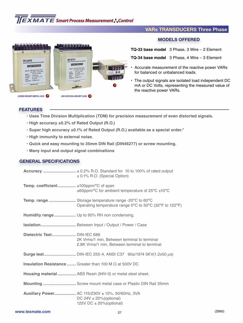
TQ-33 base model 3 Phase, 3 Wire – 2 Element
TQ-34 base model 3 Phase, 4 Wire – 3 Element
• Accurate measurement of the reactive power VARs for balanced or unbalanced loads.
• The output signals are isolated load independent DC mA or DC Volts, representing the measured value of the reactive power VARs.
• Uses Time Division Multiplication (TDM) for precision measurement of even distorted signals.• High accuracy ±0.2% of Rated Output (R.O.)• Super high accuracy ±0.1% of Rated Output (R.O.) available as a special order.*• High immunity to external noise.• Quick and easy mounting to 35mm DIN Rail (DIN46277) or screw mounting.• Many input and output signal combinations
GENERAL SPECIFICATIONS
Accuracy ............................. ± 0.2% R.O. Standard for 10 to 100% of rated output ± 0.1% R.O. (Special Option)
Temp. coefficient ................ ≤100ppm/ºC of span ≤60ppm/ºC for ambient temperature of 25ºC ±10ºC
Temp. range ........................ Storage temperature range -20ºC to 60ºC Operating temperature range 0ºC to 50ºC (32ºF to 122ºF)
Humidity range ................... Up to 95% RH non condensing.
Isolation ............................... Between Input / Output / Power / Case
Dielectric Test ..................... DIN-IEC 688 2K Vrms/1 min, Between terminal to terminal 2.8K Vrms/1 min, Between terminal to terminal
Surge test ............................ DIN-IEC 255-4, ANSI C37 90a/1974 5KV(1.2x50 µs)
Insulation Resistance ........ Greater than 100 M Ω at 500V DC
Housing material ................ ABS Resin (94V-0) or metal steel sheet.
Mounting ............................. Screw mount metal case or Plastic DIN Rail 35mm
Auxiliary Power................... AC 115/230V ± 15%, 50/60Hz, 3VA DC 24V ± 20%(optional) 125V DC ± 20%(optional)
VARs TRANSDUCERS Three Phase

(Z660)www.texmate.com 28
VARs TRANSDUCERS Three Phase
INPUT SPECIFICATIONSAC Input ............................... 120V / 5A AC, 240V /5A AC for 3 phase/3 Wire
208V/120V & 5A AC, 416V/240V & 5A AC, for 3 Phase / 4 Wire custom input (600V max /10A AC max)
Frequency ........................... 60Hz ±3Hz, 50Hz ±3Hz, 400Hz ±3Hz
Burden ................................. ≤0.2VA per current circuit, ≤0.1VA per voltage circuit.
Response Sensitivity ......... ≤0.5% of measuring range to maximum input range
Input Voltage ....................... 600V AC rms continuous Overload Capacity 1.25 times the rated input Voltage continuously. 2 times the rated input Voltage for 10 secs. 4 times the rated input Voltage for 5 secs.
Input Current ....................... 3 times the rated input current continuously. Overload Capacity 10 times the rated input current for 10 secs. 50 times the rated input current for 1 sec. 80 times the rated input current for 0.5 secs
OUTPUT SPECIFICATIONS
Output Variables ................. DC mA or DC Volts
Ripple ................................... < 0.5% of rated output. Peak to Peak (maximum)
Response Time ................... < 400 milliseconds to go from 0 to 99% of output
Zero Adjustment ................. ± 5% of rated output (minimum)
Span Adjustment ................ ± 10% of rated output (minimum)
Load Resistance ................. 10 kΩ maximum for 0 to 1mA output 500 Ω maximum for 4 to 20mA output 500 Ω minimum for 0 to 10V output
Model Voltage Current Nominal VARsTQ-33 3 ø / 3 Wire 120V AC (110V) 5A AC 1000
TQ-33 3 ø / 3 Wire 240V AC (220V) 5A AC 2000
TQ-34 3 ø / 4 Wire 208V/120V AC (190V/110V)phase volts / line volts
5A AC 1500
TQ-34 3 ø / 4 Wire 416V/240V AC (380V/220V)phase volts / line volts
5A AC 3000
Maximum Input range value = (CT Ratio) X (PT Ratio) X (Nominal VARs)
If CT = 200A:5A PT is 3300V:110V Nominal VARs = 1000 then CT Ratio = 40 then PT Ratio = 30 and Maximum input range value = 40 x 30 x 1000 = 1200KVAR

(Z660)www.texmate.com 29
CONNECTION DIAGRAM
+OUTPUT
OUTPUT+
ACPOWER230 V
115 V
L1 C.T.1
P2 P3P1
1S 1L 3S 3L
C.T.3
P.T.1 P.T.3
L2
L3
1 2 3 4 5 6 7 8 9
10 11 12 13 14 15 16 17 18
+OUTPUT
OUTPUT+
ACPOWER230 V
115 V
L1C.T.1
P2 P3P1P0
1S 1L 2S 2L 3S 3L
C.T.3C.T.2
P.T.
2
P.T.
1
P.T.
3
L2
L3
N
1 2 3 4 5 6 7 8 9
10 11 12 13 14 15 16 17 18
TQ-33
TQ-34
VARs TRANSDUCERS Three Phase

(Z660)www.texmate.com 30
Example:Product Ordering Code of TQ-3312121
TQ-33: Three Phase / 3Wire, 2 element VARs Transducer1: 120 V and 5A AC Input2: 50Hz ± 3Hz1: 0 to 1mA DC Output2: 24V DC Power1: Plastic Case
ORDERING INFORMATION
3 Phase/ 3 Wire, 2 element
60Hz ± 3Hz
120 V and 5A AC
240 V and 5A ACCustom Input Range
(600V AC, 10Amps Max)
115V AC / 230V AC Power
24V DC Power
125 V DC Power
Custom Power
Plastic Case DIN Rail mountCase D
Metal Case Screw mountCase B
3 Phase/ 4 Wire, 3 element
50Hz ± 3Hz
Custom 400Hz ± 3Hz
TQ-34
2Y
TQ-33
1
Y21
Y321
3
Y
2
1
BASE UNIT INPUT OUTPUT POWER MOUNTING
2
1
FREQUENCY
0 to 1mA DC output
4 to 20mA DC output
0 to 10V DC output
Custom output Range(Max 20mA DC or 10V DC)
VARs TRANSDUCERS Three Phase

(Z660)www.texmate.com 31
MODELS OFFERED
FEATURES
Watts + VARs TRANSDUCERS Single Phase
TWQ-12 base model 1 Phase, 2 Wire – 1 Element
TWQ-13 base model 1 Phase, 3 Wire – 2 Element
• Accurate measurement of the active power and reactive power (Watts and VARs) of a single phase system with balanced or unbalanced loads.
• The output signals are isolated load independent DC mA or DC Volts, representing the measured value of the active and reactive power (Watts and VARs).
• Uses Time Division Multiplication (TDM) for precision measurement of even distorted signals.• High accuracy ±0.2% of Rated Output (R.O.)• Super high accuracy ±0.1% of Rated Output (R.O.) available as a special order.*• High immunity to external noise.• Quick and easy mounting to 35mm DIN Rail (DIN46277) or screw mounting.• Many input and output signal combinations
GENERAL SPECIFICATIONS
Accuracy ............................. ± 0.2% R.O. Standard for 10 to 100% of rated output ± 0.1% R.O. (Special Option)
Temp. coefficient ................ ≤100ppm/ºC of span ≤60ppm/ºC for ambient temperature of 25ºC ±10ºC
Temp. range ........................ Storage temperature range -20ºC to 60ºC Operating temperature range 0ºC to 50ºC (32ºF to 122ºF)
Humidity range ................... Up to 95% RH non condensing.
Isolation ............................... Between Input / Output / Power / Case
Dielectric Test ..................... DIN-IEC 688 2K Vrms/1 min, Between terminal to terminal 2.8K Vrms/1 min, Between terminal to terminal
Surge test ............................ DIN-IEC 255-4, ANSI C37 90a/1974 5KV(1.2x50 µs)
Insulation Resistance ........ Greater than 100 M Ω at 500V DC
Housing material ................ ABS Resin (94V-0) or metal steel sheet.
Mounting ............................. Screw mount metal case or Plastic DIN Rail 35mm
Auxiliary Power................... AC 115/230V ± 15%, 50/60Hz, 3VA DC 24V ± 20%(optional) 125V DC ± 20%(optional)

(Z660)www.texmate.com 32
INPUT SPECIFICATIONSAC Input ............................... 120V / 5A AC, 240V /5A AC for 3 phase/3 Wire
208V/120V & 5A AC, 416V/240V & 5A AC, for 3 Phase / 4 Wire custom input (600V max /10A AC max
Frequency ........................... 60Hz ±3Hz, 50Hz ±3Hz, 400Hz ±3Hz
Burden ................................. ≤0.2VA per current circuit, ≤0.1VA per voltage circuit.
Response Sensitivity ......... ≤0.5% of measuring range to maximum input range
Input Voltage ....................... 600V AC rms continuous Overload Capacity 1.25 times the rated input Voltage continuously. 2 times the rated input Voltage for 10 secs. 4 times the rated input Voltage for 5 secs.
Input Current ....................... 3 times the rated input current continuously. Overload Capacity 10 times the rated input current for 10 secs. 50 times the rated input current for 1 sec. 80 times the rated input current for 0.5 secs
OUTPUT SPECIFICATIONS
Output Variables ................. DC mA or DC Volts
Ripple ................................... < 0.5% of rated output. Peak to Peak (maximum)
Response Time ................... < 400 milliseconds to go from 0 to 99% of output
Zero Adjustment ................. ± 5% of rated output (minimum)
Span Adjustment ................ ± 10% of rated output (minimum)
Load Resistance ................. 10 kΩ maximum for 0 to 1mA output 500 Ω maximum for 4 to 20mA output 500 Ω minimum for 0 to 10V output
Model Voltage Current Nominal Watts Nominal VARsTWQ-12 1 ø / 2 Wire 120V AC (110V) 5A AC 500 500
TWQ-12 1 ø / 2 Wire 240V AC (220V) 5A AC 1000 1000
TWQ-13 1 ø / 3 Wire 240V/120V AC (220V/110V)Phase volts/Line Volts
5A AC 1000 1000
To calculate the actual Watts and VARs Maximum Input range value, the CT and PT ratios have to be factored in
Maximum input Range for Watts = (CT Ratio) X (PT Ratio) X (Nominal Watts)
Maximum Input range value for VARs = (CT Ratio) X (PT Ratio) X (Nominal VARs)
Watts + VARs TRANSDUCERS Single Phase

(Z660)www.texmate.com 33
CONNECTION DIAGRAM
+WATT
OUTPUT
OUTPUT+
ACPOWER230 V
115 V
LC.T.1
P.T.1
N
1S 1L
P1 P2
+VAR
OUTPUT
1 2 3 4 5 6 7 8 9
10 11 12 13 14 15 16 17 18
+WATT
OUTPUT +VAE
OUTPUT
OUTPUT+
ACPOWER230 V
115 V
L1 C.T.1
P0 P2P1
1S 1L 3S 3L
C.T.3
P.T.1 P.T.2
L2
N
1 2 3 4 5 6 7 8 9
10 11 12 13 14 15 16 17 18
TWQ-12
TWQ-13
OUTPUT SPECIFICATIONS (CONTINUED)
For example:If CT = 200A:5A PT is 3300V:110V Nominal Watts = 1000 Nominal VARs = 1000 then CT Ratio = 40 then PT Ratio = 30 and
Maximum input range value for Watts = 40 x 30 x 1000 = 1200KWattsMaximum input range value for VARs = 40 x 30 x 1000 = 1200KVARs
Watts + VARs TRANSDUCERS Single Phase

(Z660)www.texmate.com 34
Example:Product Ordering Code of TWQ-1212121
TWQ-12: Single Phase / 2Wire, 1 element WATT+ VARs Transducer1: 120 V and 5A AC Input2: 50Hz ± 3Hz1: 0 to 1mA DC Output2: 24V DC Power1: Plastic Case
ORDERING INFORMATION
1 Phase/ 2 Wire, 1 element
60Hz ± 3Hz
120 V and 5A AC
240 V and 5A ACCustom Input Range
(600V AC, 10Amps Max)
115V AC / 230V AC Power
24V DC Power
125 V DC Power
Custom Power
Plastic Case DIN Rail mountCase D
Metal Case Screw mountCase B
1 Phase/ 3 Wire, 2 element
50Hz ± 3Hz
Custom 400Hz ± 3Hz
TWQ-13
2Y
TWQ-12
1
Y21
Y321
3
Y
2
1
BASE UNIT INPUT OUTPUT POWER MOUNTING
2
1
FREQUENCY
0 to 1mA DC output
4 to 20mA DC output
0 to 10V DC output
Custom output Range(Max 20mA DC or 10V DC)
Watts + VARs TRANSDUCERS Single Phase

(Z660)www.texmate.com 35
MODELS OFFERED
FEATURES
TWQ-33 base model 3 Phase, 3 Wire – 2 Element
TWQ-34 base model 3 Phase, 4 Wire – 3 Element
• Accurate measurement of the active power and reactive power (Watts and VARs) of a three phase system with balanced or unbalanced loads.
• The output signals are isolated load independent DC mA or DC Volts, representing the measured value of the active and reactive power (Watts and VARs).
• Uses Time Division Multiplication (TDM) for precision measurement of even distorted signals.• High accuracy ±0.2% of Rated Output (R.O.)• Super high accuracy ±0.1% of Rated Output (R.O.) available as a special order.*• High immunity to external noise.• Quick and easy mounting to 35mm DIN Rail (DIN46277) or screw mounting.• Many input and output signal combinations
GENERAL SPECIFICATIONS
Accuracy ............................. ± 0.2% R.O. Standard for 10 to 100% of rated output ± 0.1% R.O. (Special Option)
Temp. coefficient ................ ≤100ppm/ºC of span ≤60ppm/ºC for ambient temperature of 25ºC ±10ºC
Temp. range ........................ Storage temperature range -20ºC to 60ºC Operating temperature range 0ºC to 50ºC (32ºF to 122ºF)
Humidity range ................... Up to 95% RH non condensing.
Isolation ............................... Between Input / Output / Power / Case
Dielectric Test ..................... DIN-IEC 688 2K Vrms/1 min, Between terminal to terminal 2.8K Vrms/1 min, Between terminal to terminal
Surge test ............................ DIN-IEC 255-4, ANSI C37 90a/1974 5KV(1.2x50 µs)
Insulation Resistance ........ Greater than 100 M Ω at 500V DC
Housing material ................ ABS Resin (94V-0) or metal steel sheet.
Mounting ............................. Screw mount metal case or Plastic DIN Rail 35mm
Auxiliary Power................... AC 115/230V ± 15%, 50/60Hz, 3VA DC 24V ± 20%(optional) 125V DC ± 20%(optional)
Watts + VARs TRANSDUCERS Three Phase

(Z660)www.texmate.com 36
INPUT SPECIFICATIONSAC Input ............................... 120V / 5A AC, 240V /5A AC for 3 phase/3 Wire
208V/120V & 5A AC, 416V/240V & 5A AC, for 3 Phase / 4 Wire custom input (600V max /10A AC max
Frequency ........................... 60Hz ±3Hz, 50Hz ±3Hz, 400Hz ±3Hz
Burden ................................. ≤0.2VA per current circuit, ≤0.1VA per voltage circuit.
Response Sensitivity ......... ≤0.5% of measuring range to maximum input range
Input Voltage ....................... 600V AC rms continuous Overload Capacity 1.25 times the rated input Voltage continuously. 2 times the rated input Voltage for 10 secs. 4 times the rated input Voltage for 5 secs.
Input Current ....................... 3 times the rated input current continuously. Overload Capacity 10 times the rated input current for 10 secs. 50 times the rated input current for 1 sec. 80 times the rated input current for 0.5 secs
OUTPUT SPECIFICATIONS
Output Variables ................. DC mA or DC Volts
Ripple ................................... < 0.5% of rated output. Peak to Peak (maximum)
Response Time ................... < 400 milliseconds to go from 0 to 99% of output
Zero Adjustment ................. ± 5% of rated output (minimum)
Span Adjustment ................ ± 10% of rated output (minimum)
Load Resistance ................. 10 kΩ maximum for 0 to 1mA output 500 Ω maximum for 4 to 20mA output 500 Ω minimum for 0 to 10V output
Model Voltage Current Nominal Watts Nominal VARsTWQ-33 3 ø / 3 Wire 120V AC (110V) 5A AC 1000 1000
TWQ-33 3 ø / 3Wire 240V AC (220V) 5A AC 2000 2000
TWQ-34 3 ø / 4 Wire 208V/120V AC (190V/110V)phase volts / line volts
5A AC 1500 1500
TWQ-34 3 ø / 4 Wire 416V/240V AC (380V/220V)phase volts / line volts
5A AC 3000 3000
To calculate the actual Watts and VARs Maximum Input range value, the CT and PT ratios have to be factored in
Maximum input Range for Watts = (CT Ratio) X (PT Ratio) X (Nominal Watts)
Maximum Input range value for VARs = (CT Ratio) X (PT Ratio) X (Nominal VARs)
Watts + VARs TRANSDUCERS Three Phase

(Z660)www.texmate.com 37
CONNECTION DIAGRAM
OUTPUT+
ACPOWER230 V
115 V
L1 C.T.1
P2 P3P1
1S 1L 3S 3L
C.T.3
P.T.1 P.T.3
L2
L3
+WATT
OUTPUT +VAR
OUTPUT
1 2 3 4 5 6 7 8 9
10 11 12 13 14 15 16 17 18
OUTPUT+
ACPOWER230 V
115 V
L1C.T.1
P2 P3P1P0
1S 1L 2S 2L 3S 3L
C.T.3C.T.2
P.T.
2
P.T.
1
P.T.
3
L2
L3
N
+WATT
OUTPUT +VAR
OUTPUT
1 2 3 4 5 6 7 8 9
10 11 12 13 14 15 16 17 18
TWQ-33
TWQ-34
OUTPUT SPECIFICATIONS (CONTINUED)
For example:If CT = 200A:5A PT is 3300V:110V Nominal Watts = 1000 Nominal VARs = 1000 then CT Ratio = 40 then PT Ratio = 30 and
Maximum input range value for Watts = 40 x 30 x 1000 = 1200KWattsMaximum input range value for VARs = 40 x 30 x 1000 = 1200KVARs
Watts + VARs TRANSDUCERS Three Phase

(Z660)www.texmate.com 38
Example:Product Ordering Code of TWQ-3312121
TWQ-33: Three Phase / 3Wire, 2 element WATT+ VARs Transducer1: 120 V and 5A AC Input2: 50Hz ± 3Hz1: 0 to 1mA DC Output2: 24V DC Power1: Plastic Case
ORDERING INFORMATION
3 Phase/ 3 Wire, 2 element
60Hz ± 3Hz
120 V and 5A AC
240 V and 5A ACCustom Input Range
(600V AC, 10Amps Max)
115V AC / 230V AC Power
24V DC Power
125 V DC Power
Custom Power
Plastic Case DIN Rail mountCase D
Metal Case Screw mountCase B
3 Phase/ 4 Wire, 3 element
50Hz ± 3Hz
Custom 400Hz ± 3Hz
TWQ-34
2Y
TWQ-33
1
Y21
Y321
3
Y
2
1
BASE UNIT INPUT OUTPUT POWER MOUNTING
2
1
FREQUENCY
0 to 1mA DC output
4 to 20mA DC output
0 to 10V DC output
Custom output Range(Max 20mA DC or 10V DC)
Watts + VARs TRANSDUCERS Three Phase

(Z660)www.texmate.com 39
MODELS OFFERED
FEATURES
TWH-12 base model 1 Phase, 2 Wire – 1 Element
TWH-13 base model 1 Phase, 3 Wire – 2 Element
• Accurate measurement of the active energy (Watt Hours) of a single phase system with balanced or unbalanced loads.
• The output signals are isolated load independent DC mA or DC Volts, representing the measured value of the active energy (WattHours, forward and reverse).
• Uses Time Division Multiplication (TDM) for precision measurement of even distorted signals.• High accuracy ±0.2% of Rated Output (R.O.)• Super high accuracy ±0.1% of Rated Output (R.O.) available as a special order.*• High immunity to external noise.• Quick and easy mounting to 35mm DIN Rail (DIN46277) or screw mounting.• Many input and output signal combinations.
GENERAL SPECIFICATIONS
Accuracy ............................. ± 0.2% R.O. Standard for 10 to 100% of rated output ± 0.1% R.O. (Special Option)
Temp. coefficient ................ ≤100ppm/ºC of span ≤60ppm/ºC for ambient temperature of 25ºC ±10ºC
Temp. range ........................ Storage temperature range -20ºC to 60ºC Operating temperature range 0ºC to 50ºC (32ºF to 122ºF)
Humidity range ................... Up to 95% RH non condensing.
Isolation ............................... Between Input / Output / Power / Case
Dielectric Test ..................... DIN-IEC 688 2K Vrms/1 min, Between terminal to terminal 2.8K Vrms/1 min, Between terminal to terminal
Surge test ............................ DIN-IEC 255-4, ANSI C37 90a/1974 5KV(1.2x50 µs)
Insulation Resistance ........ Greater than 100 M Ω at 500V DC
Housing material ................ ABS Resin (94V-0) or metal steel sheet.
Mounting ............................. Screw mount metal case or Plastic DIN Rail 35mm
Auxiliary Power................... AC 115/230V ± 15%, 50/60Hz, 3VA DC 24V ± 20%(optional) 125V DC ± 20%(optional)
Watt Hours TRANSDUCERS Single Phase

(Z660)www.texmate.com 40
Watt Hours TRANSDUCERS Single Phase
INPUT SPECIFICATIONSAC Input ............................... 120V / 5A AC, 240V /5A AC for 1 phase/2 Wire
240V/120V & 5A AC, for 1 Phase / 3 Wire custom input (600V max /10A AC max)
Frequency ........................... 60Hz ±3Hz, 50Hz ±3Hz, 400Hz ±3Hz
Burden ................................. ≤0.2VA per current circuit, ≤0.1VA per voltage circuit.
Response Sensitivity ......... ≤0.5% of measuring range to maximum input range
Input Voltage ....................... 600V AC rms continuous Overload Capacity 1.25 times the rated input Voltage continuously. 2 times the rated input Voltage for 10 secs. 4 times the rated input Voltage for 5 secs.
Input Current ....................... 3 times the rated input current continuously. Overload Capacity 10 times the rated input current for 10 secs. 50 times the rated input current for 1 sec. 80 times the rated input current for 0.5 secs
OUTPUT SPECIFICATIONSOutput Variables ................. Pulses
Ripple ................................... < 0.5% of rated output. Peak to Peak (maximum)
Response Time ................... < 400 milliseconds to go from 0 to 99% of output
Zero Adjustment ................. ± 5% of rated output (minimum)
Span Adjustment ................ ± 10% of rated output (minimum)
Model Voltage Current Nominal Watts Nominal Pulses/WattHours
with NO CT or PTTWH-12 1 ø / 2 Wire 120V AC (110V) 5A AC 500 1, 10, 100
TWH-12 1 ø / 2 Wire 240V AC (220V) 5A AC 1000 1, 10, 100
TWH-13 1 ø / 3 Wire 240V/120V AC (220V/110V)phase volts / line volts
5A AC 1000 1, 10, 100
To calculate the actual WattHours for each output pulse, the CT and PT ratios have to be factored in
WattHours per Output Pulse = (CT Ratio) X (PT Ratio) Nominal Pulses /WattHour

(Z660)www.texmate.com 41
CONNECTION DIAGRAM
OUTPUT+ +
ACPOWER230 V
115 V
L C.T.1
P2P1
1S 1L 3S 3L
P.T.1
N
+ +FORW
ARD
PULS
E O
UTPU
T
REVE
RSE
1 2 3 4 5 6 7 8 9
10 11 12 13 14 15 16 17 18
OUTPUT+ +
ACPOWER230 V
115 V
L1 C.T.1
P2 P3P1
1S 1L 3S 3L
C.T.3
P.T.1 P.T.3
N
L2
+ +FORW
ARD
PULS
E O
UTPU
T
REVE
RSE
1 2 3 4 5 6 7 8 9
10 11 12 13 14 15 16 17 18
TWH-12
TWH-13
OUTPUT SPECIFICATIONS (CONTINUED)
Calculation example: For Single phase 2 wire, TWH-12If CT = 200A:5A then CT Ratio = 40 PT is 3300V:110V then PT Ratio = 30
If 1 pulse per WattHour is selected, the output will actually be 1 pulse per 1200 WattHoursIf 10 pulse per WattHour is selected, the output will actually be 1 pulse per 120 WattHoursIf 100 pulse per WattHour is selected, the output will actually be 1 pulse per 12 WattHours
Watt Hours TRANSDUCERS Single Phase

(Z660)www.texmate.com 42
Example:Product Ordering Code of TWH-12121221
TWH-12: Single Phase / 2Wire, 1 element Watt Hours Transducer1: 120 V and 5A AC Input2: 50Hz ± 3Hz1: Reed Relay. Forward only2:10 pulses per WattHour2: 24V DC Power1: Plastic Case
ORDERING INFORMATION
1 Phase/ 2 Wire, 1 element
60Hz ± 3Hz
120 V and 5A AC
240 V and 5A ACCustom Input Range
(600V AC, 10Amps Max)
115V AC / 230V AC Power
1 pulse per WattHour
24V DC Power
10 pulses per WattHour
125 V DC Power
100 pulses per WattHour
Custom Power
Custom Output pulses per WattHour
Plastic Case DIN Rail mountCase D
Metal Case Screw mountCase B
1 Phase/ 3 Wire, 2 element
50Hz ± 3Hz
Custom 400Hz ± 3Hz
TWH-13
2Y
TWH-12
1
Y21
4321
3
3
Y
Y
2
2
1
1
BASE UNIT INPUTFrequencyOUTPUT POWER
Pulses perWatthour MOUNTING
21
FREQUENCY
Reed Relay. Forward only
Reed Relay. Forward and Reverse
Open Collector. Forward only
Open Collector. Forward and Reverse
Watt Hours TRANSDUCERS Single Phase

(Z660)www.texmate.com 43
MODELS OFFERED
FEATURES
TWH-33 base model 3 Phase, 3 Wire – 2 Element
TWH-34 base model 3 Phase, 4 Wire – 3 Element
• Accurate measurement of the active energy (Wat-tHours) of a three phase system with balanced or unbalanced loads.
• The output signals are isolated load independent pulses, representing the measured value of the ac-tive energy (WattHours, forward and reverse).
• Uses Time Division Multiplication (TDM) for precision measurement of even distorted signals.• High accuracy ±0.2% of Rated Output (R.O.)• Super high accuracy ±0.1% of Rated Output (R.O.) available as a special order.*• High immunity to external noise.• Quick and easy mounting to 35mm DIN Rail (DIN46277) or screw mounting.• Many input and output signal combinations.
GENERAL SPECIFICATIONS
Accuracy ............................. ± 0.2% R.O. Standard for 10 to 100% of rated output ± 0.1% R.O. (Special Option)
Temp. coefficient ................ ≤100ppm/ºC of span ≤60ppm/ºC for ambient temperature of 25ºC ±10ºC
Temp. range ........................ Storage temperature range -20ºC to 60ºC Operating temperature range 0ºC to 50ºC (32ºF to 122ºF)
Humidity range ................... Up to 95% RH non condensing.
Isolation ............................... Between Input / Output / Power / Case
Dielectric Test ..................... DIN-IEC 688 2K Vrms/1 min, Between terminal to terminal 2.8K Vrms/1 min, Between terminal to terminal
Surge test ............................ DIN-IEC 255-4, ANSI C37 90a/1974 5KV(1.2x50 µs)
Insulation Resistance ........ Greater than 100 M Ω at 500V DC
Housing material ................ ABS Resin (94V-0) or metal steel sheet.
Mounting ............................. Screw mount metal case or Plastic DIN Rail 35mm
Auxiliary Power................... AC 115/230V ± 15%, 50/60Hz, 3VA DC 24V ± 20%(optional) 125V DC ± 20%(optional)
Watt Hours TRANSDUCERS Three Phase

(Z660)www.texmate.com 44
Watt Hours TRANSDUCERS Three Phase
INPUT SPECIFICATIONSAC Input ............................... 120V / 5A AC, 240V /5A AC for 3 phase/3 Wire
208V/120V & 5A AC, 416V/240V, 5A, for 3 Phase / 4 Wire custom input (600V max /10A AC max)
Frequency ........................... 60Hz ±3Hz, 50Hz ±3Hz, 400Hz ±3Hz
Burden ................................. ≤0.2VA per current circuit, ≤0.1VA per voltage circuit.
Response Sensitivity ......... ≤0.5% of measuring range to maximum input range
Input Voltage ....................... 600V AC rms continuous Overload Capacity 1.25 times the rated input Voltage continuously. 2 times the rated input Voltage for 10 secs. 4 times the rated input Voltage for 5 secs.
Input Current ....................... 3 times the rated input current continuously. Overload Capacity 10 times the rated input current for 10 secs. 50 times the rated input current for 1 sec. 80 times the rated input current for 0.5 secs
OUTPUT SPECIFICATIONSOutput Variables ................. Pulses
Ripple ................................... < 0.5% of rated output. Peak to Peak (maximum)
Response Time ................... < 400 milliseconds to go from 0 to 99% of output
Zero Adjustment ................. ± 5% of rated output (minimum)
Span Adjustment ................ ± 10% of rated output (minimum)
Model Voltage Current Nominal Watts Nominal Pulses/WattHours
with NO CT or PTTWH-33 3 ø / 3 Wire 120V AC (110V) 5A AC 1000 1, 10, 100
TWH-33 3 ø / 3 Wire 240V AC (220V) 5A AC 2000 1, 10, 100
TWH-34 3 ø / 4 Wire 208V/120V AC (190V/110V)Phase volts/Line Volts
5A AC 1500 1, 10, 100
TWH-34 3 ø / 4 Wire 416V/240V AC (380V/220V)Phase volts/Line Volts
5A AC 3000 1, 10, 100
To calculate the actual WattHours for each output pulse, the CT and PT ratios have to be factored in
WattHours per Output Pulse = (CT Ratio) X (PT Ratio) Nominal Pulses /WattHour

(Z660)www.texmate.com 45
CONNECTION DIAGRAM
ACPOWER230 V
115 V
L1 C.T.1
P2 P3P1
1S 1L 3S 3L
C.T.3
P.T.1 P.T.3
L2
L3
OUTPUT+ +
+ +FORW
ARD
PULS
E O
UTPU
T
REVE
RSE
1 2 3 4 5 6 7 8 9
10 11 12 13 14 15 16 17 18
ACPOWER230 V
115 V
L1C.T.1
P2 P3P1P0
1S 1L 2S 2L 3S 3L
C.T.3C.T.2
P.T.
2
P.T.
1
P.T.
3
L2
L3
N
OUTPUT+ +
+ +FORW
ARD
PULS
E O
UTPU
T
REVE
RSE
1 2 3 4 5 6 7 8 9
10 11 12 13 14 15 16 17 18
TWH-33
TWH-34
OUTPUT SPECIFICATIONS (CONTINUED)
Calculation example: For Three phase 3 wire, TWH-33If CT = 200A:5A then CT Ratio = 40 PT is 3300V:110V then PT Ratio = 30
If 1 pulse per WattHour is selected, the output will actually be 1 pulse per 1200 WattHoursIf 10 pulse per WattHour is selected, the output will actually be 1 pulse per 120 WattHoursIf 100 pulse per WattHour is selected, the output will actually be 1 pulse per 12 WattHours
Watt Hours TRANSDUCERS Three Phase

(Z660)www.texmate.com 46
Example:Product Ordering Code of TWH-33121221
TWH-12: Three Phase / 3Wire, 2 element Watt Hours Transducer1: 120 V and 5A AC Input2: 50Hz ± 3Hz1: Reed Relay. Forward only2:10 pulses per WattHour2: 24V DC Power1: Plastic Case
ORDERING INFORMATION
3 Phase/ 3 Wire, 2 element
60Hz ± 3Hz
120 V and 5A AC
240 V and 5A ACCustom Input Range
(600V AC, 10Amps Max)
115V AC / 230V AC Power
1 pulse per WattHour
24V DC Power
10 pulses per WattHour
125 V DC Power
100 pulses per WattHour
Custom Power
Custom Output pulses per WattHour
Plastic Case DIN Rail mountCase D
Metal Case Screw mountCase B
3 Phase/ 4 Wire, 3 element
50Hz ± 3Hz
Custom 400Hz ± 3Hz
TWH-34
2Y
TWH-33
1
Y21
4321
3
3
Y
Y
2
2
1
1
BASE UNIT INPUTFrequencyOUTPUT POWER
Pulses perWatthour MOUNTING
21
FREQUENCY
Reed Relay. Forward only
Reed Relay. Forward and Reverse
Open Collector. Forward only
Open Collector. Forward and Reverse
Watt Hours TRANSDUCERS Three Phase
(Z660)www.texmate.com 47
MODELS OFFERED
FEATURES
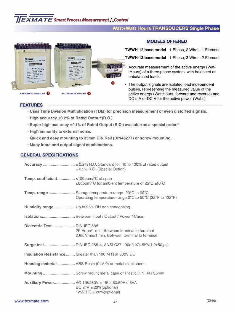
TWWH-12 base model 1 Phase, 2 Wire – 1 Element
TWWH-13 base model 1 Phase, 3 Wire – 2 Element
• Accurate measurement of the active energy (Wat-tHours) of a three phase system with balanced or unbalanced loads.
• The output signals are isolated load independent pulses, representing the measured value of the active energy (WattHours, forward and reverse) and DC mA or DC V for the active power (Watts).
• Uses Time Division Multiplication (TDM) for precision measurement of even distorted signals.• High accuracy ±0.2% of Rated Output (R.O.)• Super high accuracy ±0.1% of Rated Output (R.O.) available as a special order.*• High immunity to external noise.• Quick and easy mounting to 35mm DIN Rail (DIN46277) or screw mounting.• Many input and output signal combinations.
GENERAL SPECIFICATIONS
Accuracy ............................. ± 0.2% R.O. Standard for 10 to 100% of rated output ± 0.1% R.O. (Special Option)
Temp. coefficient ................ ≤100ppm/ºC of span ≤60ppm/ºC for ambient temperature of 25ºC ±10ºC
Temp. range ........................ Storage temperature range -20ºC to 60ºC Operating temperature range 0ºC to 50ºC (32ºF to 122ºF)
Humidity range ................... Up to 95% RH non condensing.
Isolation ............................... Between Input / Output / Power / Case
Dielectric Test ..................... DIN-IEC 688 2K Vrms/1 min, Between terminal to terminal 2.8K Vrms/1 min, Between terminal to terminal
Surge test ............................ DIN-IEC 255-4, ANSI C37 90a/1974 5KV(1.2x50 µs)
Insulation Resistance ........ Greater than 100 M Ω at 500V DC
Housing material ................ ABS Resin (94V-0) or metal steel sheet.
Mounting ............................. Screw mount metal case or Plastic DIN Rail 35mm
Auxiliary Power................... AC 115/230V ± 15%, 50/60Hz, 3VA DC 24V ± 20%(optional) 125V DC ± 20%(optional)
Watt+Watt Hours TRANSDUCERS Single Phase

(Z660)www.texmate.com 48
Watt+Watt Hours TRANSDUCERS Single Phase
INPUT SPECIFICATIONSAC Input ............................... 120V / 5A AC, 240V /5A AC for 1 phase/2 Wire
208V/120V & 5A AC for 1 Phase / 3 Wire custom input (600V max /10A AC max)
Frequency ........................... 60Hz ±3Hz, 50Hz ±3Hz, 400Hz ±3Hz
Burden ................................. ≤0.2VA per current circuit, ≤0.1VA per voltage circuit.
Response Sensitivity ......... ≤0.5% of measuring range to maximum input range
Input Voltage ....................... 600V AC rms continuous Overload Capacity 1.25 times the rated input Voltage continuously. 2 times the rated input Voltage for 10 secs. 4 times the rated input Voltage for 5 secs.
Input Current ....................... 3 times the rated input current continuously. Overload Capacity 10 times the rated input current for 10 secs. 50 times the rated input current for 1 sec. 80 times the rated input current for 0.5 secs
OUTPUT SPECIFICATIONSOutput Variables ................. Pulses (WattHours) and DC mA or DC V (Watts)
Ripple ................................... < 0.5% of rated output. Peak to Peak (maximum)
Response Time ................... < 400 milliseconds to go from 0 to 99% of output
Zero Adjustment ................. ± 5% of rated output (minimum)
Span Adjustment ................ ± 10% of rated output (minimum)
Model Voltage Current Nominal Watts Nominal Pulses/WattHours
with NO CT or PTTWWH-12 1 ø / 2 Wire 120V AC (110V) 5A AC 500 1, 10, 100
TWWH-12 1 ø / 2 Wire 240V AC (220V) 5A AC 1000 1, 10, 100
TWWH-13 1 ø / 3 Wire 240V/120V AC (220V/110V)phase volts / line volts
5A AC 1000 1, 10, 100
To calculate the actual WattHours and Watts for each output pulse, the CT and PT ratios have to be factored in Watts = (CT Ratio) X (PT Ratio) x Nominal Watts
WattHours per Output Pulse = (CT Ratio) X (PT Ratio) Nominal Pulses /WattHour
(Z660)www.texmate.com 49
CONNECTION DIAGRAM
+ +
ACPOWER230 V
115 V
L C.T.1
P2P1
1S 1L 3S 3L
P.T.1
N
+ +FORW
ARD
PULS
E O
UTPU
T
REVE
RSE
PULSEOUTPUT
+DC
OUTPUT
DCOUTPUT+
1 2 3 4 5 6 7 8 9
10 11 12 13 14 15 16 17 18
PULSEOUTPUT
+ +
ACPOWER230 V
115 V
L1 C.T.1
P2 P3P1
1S 1L 3S 3L
C.T.3
P.T.1 P.T.3
N
L2
+ +FORW
ARD
PULS
E O
UTPU
T
REVE
RSE
+DC
OUTPUT
DCOUTPUT+
1 2 3 4 5 6 7 8 9
10 11 12 13 14 15 16 17 18
TWWH-12
TWWH-13
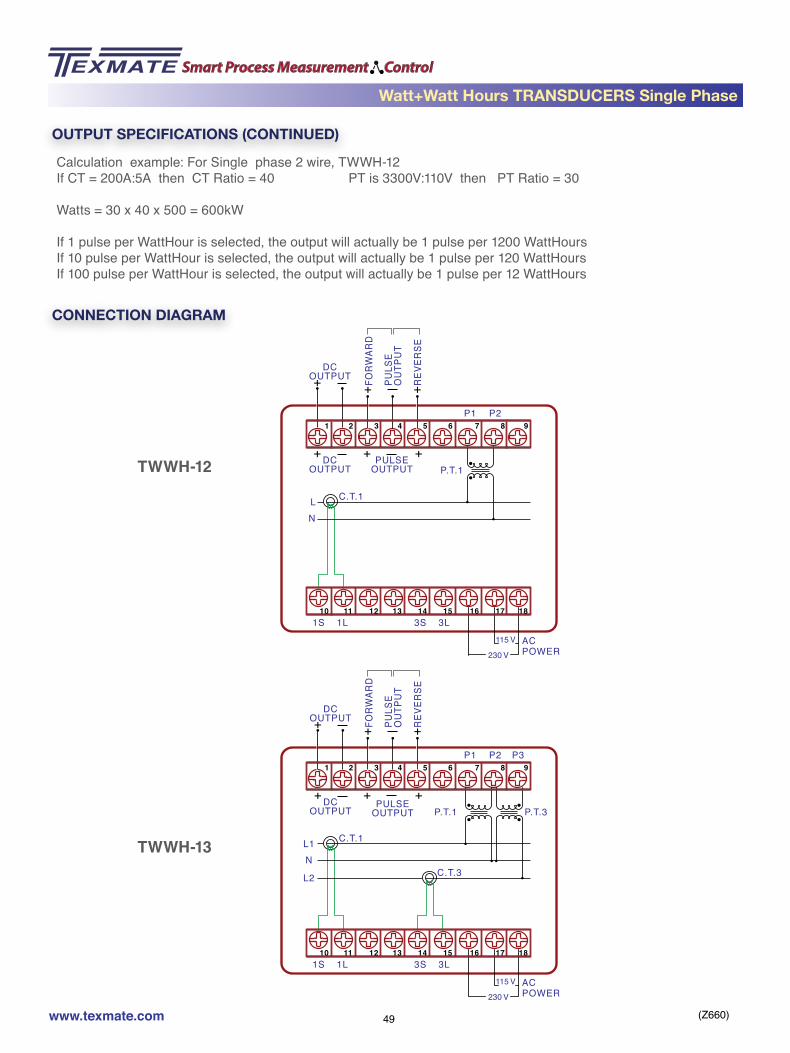
OUTPUT SPECIFICATIONS (CONTINUED)
Calculation example: For Single phase 2 wire, TWWH-12If CT = 200A:5A then CT Ratio = 40 PT is 3300V:110V then PT Ratio = 30
Watts = 30 x 40 x 500 = 600kW
If 1 pulse per WattHour is selected, the output will actually be 1 pulse per 1200 WattHoursIf 10 pulse per WattHour is selected, the output will actually be 1 pulse per 120 WattHoursIf 100 pulse per WattHour is selected, the output will actually be 1 pulse per 12 WattHours
Watt+Watt Hours TRANSDUCERS Single Phase
(Z660)www.texmate.com 50
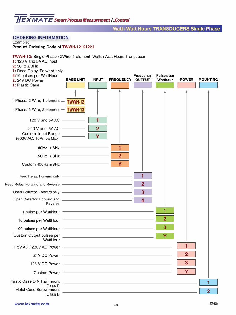
Example:Product Ordering Code of TWWH-12121221
TWWH-12: Single Phase / 2Wire, 1 element Watts+Watt Hours Transducer1: 120 V and 5A AC Input2: 50Hz ± 3Hz1: Reed Relay. Forward only2:10 pulses per WattHour2: 24V DC Power1: Plastic Case
ORDERING INFORMATION
1 Phase/ 2 Wire, 1 element
60Hz ± 3Hz
120 V and 5A AC
240 V and 5A ACCustom Input Range
(600V AC, 10Amps Max)
115V AC / 230V AC Power
1 pulse per WattHour
24V DC Power
10 pulses per WattHour
125 V DC Power
100 pulses per WattHour
Custom Power
Custom Output pulses per WattHour
Plastic Case DIN Rail mountCase D
Metal Case Screw mountCase B
1 Phase/ 3 Wire, 2 element
50Hz ± 3Hz
Custom 400Hz ± 3Hz
TWWH-13
2Y
TWWH-12
1
Y21
4321
3
3
Y
Y
2
2
1
1
BASE UNIT INPUTFrequencyOUTPUT POWER
Pulses perWatthour MOUNTING
21
FREQUENCY
Reed Relay. Forward only
Reed Relay. Forward and Reverse
Open Collector. Forward only
Open Collector. Forward and Reverse
Watt+Watt Hours TRANSDUCERS Single Phase

(Z660)www.texmate.com 51
MODELS OFFERED
FEATURES
TWWH-33 base model 3 Phase, 3 Wire – 2 Element
TWWH-34 base model 3 Phase, 4 Wire – 3 Element
• Accurate measurement of the active power and ac-tive energy (Watta and WattHours) of a three phase system with balanced or unbalanced loads.
• The output signals are isolated load independent pulses, representing the measured value of the active energy (WattHours, forward and reverse) and DC mA or DC V for active power(Watts).
• Uses Time Division Multiplication (TDM) for precision measurement of even distorted signals.• High accuracy ±0.2% of Rated Output (R.O.)• Super high accuracy ±0.1% of Rated Output (R.O.) available as a special order.*• High immunity to external noise.• Quick and easy mounting to 35mm DIN Rail (DIN46277) or screw mounting.• Many input and output signal combinations.
GENERAL SPECIFICATIONS
Accuracy ............................. ± 0.2% R.O. Standard for 10 to 100% of rated output ± 0.1% R.O. (Special Option)
Temp. coefficient ................ ≤100ppm/ºC of span ≤60ppm/ºC for ambient temperature of 25ºC ±10ºC
Temp. range ........................ Storage temperature range -20ºC to 60ºC Operating temperature range 0ºC to 50ºC (32ºF to 122ºF)
Humidity range ................... Up to 95% RH non condensing.
Isolation ............................... Between Input / Output / Power / Case
Dielectric Test ..................... DIN-IEC 688 2K Vrms/1 min, Between terminal to terminal 2.8K Vrms/1 min, Between terminal to terminal
Surge test ............................ DIN-IEC 255-4, ANSI C37 90a/1974 5KV(1.2x50 µs)
Insulation Resistance ........ Greater than 100 M Ω at 500V DC
Housing material ................ ABS Resin (94V-0) or metal steel sheet.
Mounting ............................. Screw mount metal case or Plastic DIN Rail 35mm
Auxiliary Power................... AC 115/230V ± 15%, 50/60Hz, 3VA DC 24V ± 20%(optional) 125V DC ± 20%(optional)
Watt + Watt Hours TRANSDUCERS Three Phase

(Z660)www.texmate.com 52
INPUT SPECIFICATIONSAC Input ............................... 120V / 5A AC, 240V /5A AC for 3 phase/3 Wire
208V/120V & 5A AC, 416V/240V, 5A, for 3 Phase / 4 Wire custom input (600V max /10A AC max)
Frequency ........................... 60Hz ±3Hz, 50Hz ±3Hz, 400Hz ±3Hz
Burden ................................. ≤0.2VA per current circuit, ≤0.1VA per voltage circuit.
Response Sensitivity ......... ≤0.5% of measuring range to maximum input range
Input Voltage ....................... 600V AC rms continuous Overload Capacity 1.25 times the rated input Voltage continuously. 2 times the rated input Voltage for 10 secs. 4 times the rated input Voltage for 5 secs.
Input Current ....................... 3 times the rated input current continuously. Overload Capacity 10 times the rated input current for 10 secs. 50 times the rated input current for 1 sec. 80 times the rated input current for 0.5 secs
OUTPUT SPECIFICATIONS
Output Variables ................. Pulses (WattHr) and DCmA or DCV (Watts)
Ripple ................................... < 0.5% of rated output. Peak to Peak (maximum)
Response Time ................... < 400 milliseconds to go from 0 to 99% of output
Zero Adjustment ................. ± 5% of rated output (minimum)
Span Adjustment ................ ± 10% of rated output (minimum)
Model Voltage Current Nominal Watts Nominal Pulses/WattHours
with NO CT or PTTWWH-33 3 ø / 3 Wire 120V AC (110V) 5A AC 1000 1, 10, 100
TWWH-33 3 ø / 3 Wire 240V AC (220V) 5A AC 2000 1, 10, 100
TWWH-34 3 ø / 4 Wire 208V/120V AC (190V/110V)Phase volts/Line Volts
5A AC 1500 1, 10, 100
TWWH-34 3 ø / 4 Wire 416V/240V AC (380V/220V)Phase volts/Line Volts
5A AC 3000 1, 10, 100
To calculate the actual WattHours for each output pulse, the CT and PT ratios have to be factored in
Watts = (CT Ratio) X (PT Ratio) X Nominal Watts
WattHours per Output Pulse = (CT Ratio) X (PT Ratio) Nominal Pulses /WattHour
Watt + Watt Hours TRANSDUCERS Three Phase

(Z660)www.texmate.com 53
CONNECTION DIAGRAM
ACPOWER230 V
115 V
L1 C.T.1
P2 P3P1
1S 1L 3S 3L
C.T.3
P.T.1 P.T.3
L2
L3
PULSEOUTPUT
+ +
+ +FORW
ARD
PULS
E O
UTPU
T
REVE
RSE
+DC
OUTPUT
DCOUTPUT
+
1 2 3 4 5 6 7 8 9
10 11 12 13 14 15 16 17 18
ACPOWER230 V
115 V
L1C.T.1
P2 P3P1P0
1S 1L 2S 2L 3S 3L
C.T.3C.T.2
P.T.
2
P.T.
1
P.T.
3
L2
L3
N
PULSEOUTPUT
+ +
+ +FORW
ARD
PULS
E O
UTPU
T
REVE
RSE
+DC
OUTPUT
DCOUTPUT
+
1 2 3 4 5 6 7 8 9
10 11 12 13 14 15 16 17 18
TWWH-33
TWWH-34
OUTPUT SPECIFICATIONS (CONTINUED)
Calculation example: For Three phase 3 wire, TWWH-33If CT = 200A:5A then CT Ratio = 40 PT is 3300V:110V then PT Ratio = 30
Watts = 40 x 30 x 1000 = 1200 KW
If 1 pulse per WattHour is selected, the output will actually be 1 pulse per 1200 WattHoursIf 10 pulse per WattHour is selected, the output will actually be 1 pulse per 120 WattHoursIf 100 pulse per WattHour is selected, the output will actually be 1 pulse per 12 WattHours
Watt + Watt Hours TRANSDUCERS Three Phase
(Z660)www.texmate.com 54
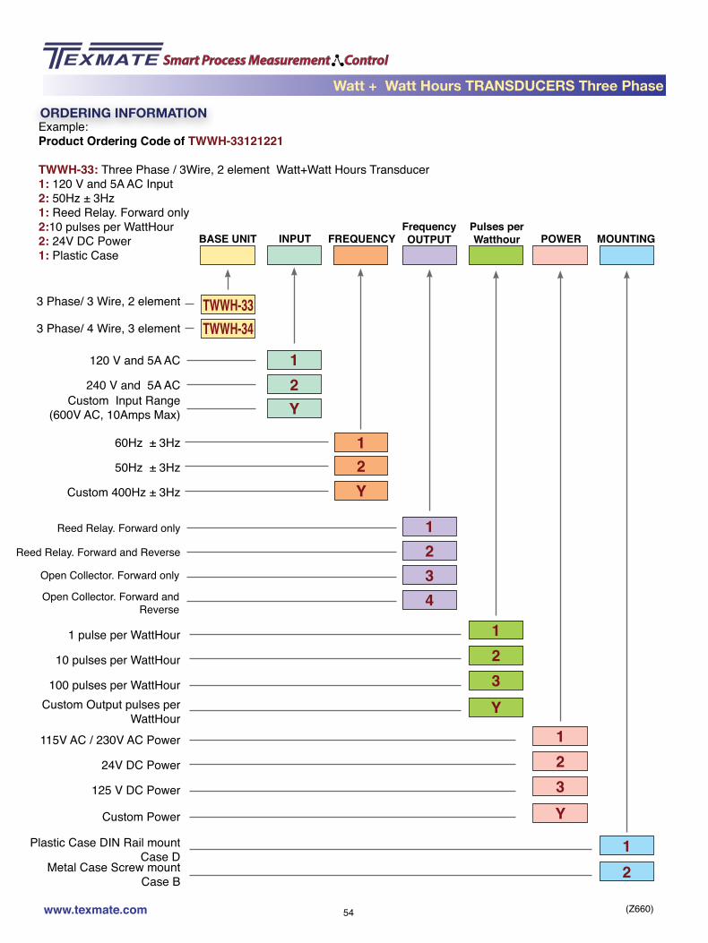
Example:Product Ordering Code of TWWH-33121221
TWWH-33: Three Phase / 3Wire, 2 element Watt+Watt Hours Transducer1: 120 V and 5A AC Input2: 50Hz ± 3Hz1: Reed Relay. Forward only2:10 pulses per WattHour2: 24V DC Power1: Plastic Case
ORDERING INFORMATION
3 Phase/ 3 Wire, 2 element
60Hz ± 3Hz
120 V and 5A AC
240 V and 5A ACCustom Input Range
(600V AC, 10Amps Max)
115V AC / 230V AC Power
1 pulse per WattHour
24V DC Power
10 pulses per WattHour
125 V DC Power
100 pulses per WattHour
Custom Power
Custom Output pulses per WattHour
Plastic Case DIN Rail mountCase D
Metal Case Screw mountCase B
3 Phase/ 4 Wire, 3 element
50Hz ± 3Hz
Custom 400Hz ± 3Hz
TWWH-34
2Y
TWWH-33
1
Y21
4321
3
3
Y
Y
2
2
1
1
BASE UNIT INPUTFrequencyOUTPUT POWER
Pulses perWatthour MOUNTING
21
FREQUENCY
Reed Relay. Forward only
Reed Relay. Forward and Reverse
Open Collector. Forward only
Open Collector. Forward and Reverse
Watt + Watt Hours TRANSDUCERS Three Phase

(Z660)www.texmate.com 55
MODELS OFFERED
FEATURES
TQH-12 base model 1 Phase, 2 Wire – 1 Element
TQH-13 base model 1 Phase, 3 Wire – 2 Element
• Accurate measurement of the reactive energy (VAR Hours) of a single phase system with balanced or unbalanced loads.
• The output signals are isolated load independent DC mA or DC Volts, representing the measured value of the active energy (WattHours, forward and reverse).
• Uses Time Division Multiplication (TDM) for precision measurement of even distorted signals.• High accuracy ±0.2% of Rated Output (R.O.)• Super high accuracy ±0.1% of Rated Output (R.O.) available as a special order.*• High immunity to external noise.• Quick and easy mounting to 35mm DIN Rail (DIN46277) or screw mounting.• Many input and output signal combinations.
GENERAL SPECIFICATIONS
Accuracy ............................. ± 0.2% R.O. Standard for 10 to 100% of rated output ± 0.1% R.O. (Special Option)
Temp. coefficient ................ ≤100ppm/ºC of span ≤60ppm/ºC for ambient temperature of 25ºC ±10ºC
Temp. range ........................ Storage temperature range -20ºC to 60ºC Operating temperature range 0ºC to 50ºC (32ºF to 122ºF)
Humidity range ................... Up to 95% RH non condensing.
Isolation ............................... Between Input / Output / Power / Case
Dielectric Test ..................... DIN-IEC 688 2K Vrms/1 min, Between terminal to terminal 2.8K Vrms/1 min, Between terminal to terminal
Surge test ............................ DIN-IEC 255-4, ANSI C37 90a/1974 5KV(1.2x50 µs)
Insulation Resistance ........ Greater than 100 M Ω at 500V DC
Housing material ................ ABS Resin (94V-0) or metal steel sheet.
Mounting ............................. Screw mount metal case or Plastic DIN Rail 35mm
Auxiliary Power................... AC 115/230V ± 15%, 50/60Hz, 3VA DC 24V ± 20%(optional) 125V DC ± 20%(optional)
VAR Hours TRANSDUCERS Single Phase
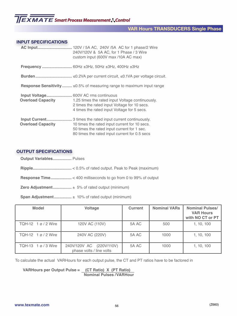
(Z660)www.texmate.com 56
VAR Hours TRANSDUCERS Single Phase
INPUT SPECIFICATIONSAC Input ............................... 120V / 5A AC, 240V /5A AC for 1 phase/2 Wire
240V/120V & 5A AC, for 1 Phase / 3 Wire custom input (600V max /10A AC max)
Frequency ........................... 60Hz ±3Hz, 50Hz ±3Hz, 400Hz ±3Hz
Burden ................................. ≤0.2VA per current circuit, ≤0.1VA per voltage circuit.
Response Sensitivity ......... ≤0.5% of measuring range to maximum input range
Input Voltage ....................... 600V AC rms continuous Overload Capacity 1.25 times the rated input Voltage continuously. 2 times the rated input Voltage for 10 secs. 4 times the rated input Voltage for 5 secs.
Input Current ....................... 3 times the rated input current continuously. Overload Capacity 10 times the rated input current for 10 secs. 50 times the rated input current for 1 sec. 80 times the rated input current for 0.5 secs
OUTPUT SPECIFICATIONSOutput Variables ................. Pulses
Ripple ................................... < 0.5% of rated output. Peak to Peak (maximum)
Response Time ................... < 400 milliseconds to go from 0 to 99% of output
Zero Adjustment ................. ± 5% of rated output (minimum)
Span Adjustment ................ ± 10% of rated output (minimum)
Model Voltage Current Nominal VARs Nominal Pulses/VAR Hours
with NO CT or PTTQH-12 1 ø / 2 Wire 120V AC (110V) 5A AC 500 1, 10, 100
TQH-12 1 ø / 2 Wire 240V AC (220V) 5A AC 1000 1, 10, 100
TQH-13 1 ø / 3 Wire 240V/120V AC (220V/110V)phase volts / line volts
5A AC 1000 1, 10, 100
To calculate the actual VARHours for each output pulse, the CT and PT ratios have to be factored in
VARHours per Output Pulse = (CT Ratio) X (PT Ratio) Nominal Pulses /VARHour

(Z660)www.texmate.com 57
CONNECTION DIAGRAM
OUTPUT+ +
ACPOWER230 V
115 V
L C.T.1
P2P1
1S 1L 3S 3L
P.T.1
N
+ +FORW
ARD
PULS
E O
UTPU
T
REVE
RSE
1 2 3 4 5 6 7 8 9
10 11 12 13 14 15 16 17 18
OUTPUT+ +
ACPOWER230 V
115 V
L1 C.T.1
P2 P3P1
1S 1L 3S 3L
C.T.3
P.T.1 P.T.3
N
L2
+ +FORW
ARD
PULS
E O
UTPU
T
REVE
RSE
1 2 3 4 5 6 7 8 9
10 11 12 13 14 15 16 17 18
TQH-12
TQH-13
OUTPUT SPECIFICATIONS (CONTINUED)
Calculation example: For Single phase 2 wire, TQH-12If CT = 200A:5A then CT Ratio = 40 PT is 3300V:110V then PT Ratio = 30
If 1 pulse per VARHour is selected, the output will actually be 1 pulse per 1200 WARHoursIf 10 pulse per VARHour is selected, the output will actually be 1 pulse per 120 VARHoursIf 100 pulse per VARHour is selected, the output will actually be 1 pulse per 12 VARHours
VAR Hours TRANSDUCERS Single Phase

(Z660)www.texmate.com 58
Example:Product Ordering Code of TQH-12121221
TQH-12: Single Phase / 2Wire, 1 element VAR Hours Transducer1: 120 V and 5A AC Input2: 50Hz ± 3Hz1: Reed Relay. Forward only2:10 pulses per WattHour2: 24V DC Power1: Plastic Case
ORDERING INFORMATION
1 Phase/ 2 Wire, 1 element
60Hz ± 3Hz
120 V and 5A AC
240 V and 5A ACCustom Input Range
(600V AC, 10Amps Max)
115V AC / 230V AC Power
1 pulse per VARHour
24V DC Power
10 pulses per VARHour
125 V DC Power
100 pulses per VARHour
Custom Power
Custom Output pulses per VARHour
Plastic Case DIN Rail mountCase D
Metal Case Screw mountCase B
1 Phase/ 3 Wire, 2 element
50Hz ± 3Hz
Custom 400Hz ± 3Hz
TQH-13
2Y
TQH-12
1
Y21
4321
3
3
Y
Y
2
2
1
1
BASE UNIT INPUTFrequencyOUTPUT POWER
Pulses perWatthour MOUNTING
21
FREQUENCY
Reed Relay. Forward only
Reed Relay. Forward and Reverse
Open Collector. Forward only
Open Collector. Forward and Reverse
VAR Hours TRANSDUCERS Single Phase

(Z660)www.texmate.com 59
MODELS OFFERED
FEATURES
TQH-33 base model 3 Phase, 3 Wire – 2 Element
TQH-34 base model 3 Phase, 4 Wire – 3 Element
• Accurate measurement of the reactive energy (VAR-Hours) of a three phase system with balanced or unbalanced loads.
• The output signals are isolated load independent pulses, representing the measured value of the reac-tive energy (VARHours, forward and reverse).
• Uses Time Division Multiplication (TDM) for precision measurement of even distorted signals.• High accuracy ±0.2% of Rated Output (R.O.)• Super high accuracy ±0.1% of Rated Output (R.O.) available as a special order.*• High immunity to external noise.• Quick and easy mounting to 35mm DIN Rail (DIN46277) or screw mounting.• Many input and output signal combinations.
GENERAL SPECIFICATIONS
Accuracy ............................. ± 0.2% R.O. Standard for 10 to 100% of rated output ± 0.1% R.O. (Special Option)
Temp. coefficient ................ ≤100ppm/ºC of span ≤60ppm/ºC for ambient temperature of 25ºC ±10ºC
Temp. range ........................ Storage temperature range -20ºC to 60ºC Operating temperature range 0ºC to 50ºC (32ºF to 122ºF)
Humidity range ................... Up to 95% RH non condensing.
Isolation ............................... Between Input / Output / Power / Case
Dielectric Test ..................... DIN-IEC 688 2K Vrms/1 min, Between terminal to terminal 2.8K Vrms/1 min, Between terminal to terminal
Surge test ............................ DIN-IEC 255-4, ANSI C37 90a/1974 5KV(1.2x50 µs)
Insulation Resistance ........ Greater than 100 M Ω at 500V DC
Housing material ................ ABS Resin (94V-0) or metal steel sheet.
Mounting ............................. Screw mount metal case or Plastic DIN Rail 35mm
Auxiliary Power................... AC 115/230V ± 15%, 50/60Hz, 3VA DC 24V ± 20%(optional) 125V DC ± 20%(optional)
VAR Hours TRANSDUCERS Three Phase

(Z660)www.texmate.com 60
VAR Hours TRANSDUCERS Three Phase
INPUT SPECIFICATIONSAC Input ............................... 120V / 5A AC, 240V /5A AC for 3 phase/3 Wire
208V/120V & 5A AC, 416V/240V, 5A, for 3 Phase / 4 Wire custom input (600V max /10A AC max)
Frequency ........................... 60Hz ±3Hz, 50Hz ±3Hz, 400Hz ±3Hz
Burden ................................. ≤0.2VA per current circuit, ≤0.1VA per voltage circuit.
Response Sensitivity ......... ≤0.5% of measuring range to maximum input range
Input Voltage ....................... 600V AC rms continuous Overload Capacity 1.25 times the rated input Voltage continuously. 2 times the rated input Voltage for 10 secs. 4 times the rated input Voltage for 5 secs.
Input Current ....................... 3 times the rated input current continuously. Overload Capacity 10 times the rated input current for 10 secs. 50 times the rated input current for 1 sec. 80 times the rated input current for 0.5 secs
OUTPUT SPECIFICATIONSOutput Variables ................. Pulses
Ripple ................................... < 0.5% of rated output. Peak to Peak (maximum)
Response Time ................... < 400 milliseconds to go from 0 to 99% of output
Zero Adjustment ................. ± 5% of rated output (minimum)
Span Adjustment ................ ± 10% of rated output (minimum)
Model Voltage Current Nominal VARs Nominal Pulses/VAR Hours
with NO CT or PTTQH-33 3 ø / 3 Wire 120V AC (110V) 5A AC 1000 1, 10, 100
TQH-33 3 ø / 3 Wire 240V AC (220V) 5A AC 2000 1, 10, 100
TQH-34 3 ø / 4 Wire 208V/120V AC (190V/110V)Phase volts/Line Volts
5A AC 1500 1, 10, 100
TQH-34 3 ø / 4 Wire 416V/240V AC (380V/220V)Phase volts/Line Volts
5A AC 3000 1, 10, 100
To calculate the actual VARHours for each output pulse, the CT and PT ratios have to be factored in
VARHours per Output Pulse = (CT Ratio) X (PT Ratio) Nominal Pulses /VARHour

(Z660)www.texmate.com 61
CONNECTION DIAGRAM
ACPOWER230 V
115 V
L1 C.T.1
P2 P3P1
1S 1L 3S 3L
C.T.3
P.T.1 P.T.3
L2
L3
OUTPUT+ +
+ +FORW
ARD
PULS
E O
UTPU
T
REVE
RSE
1 2 3 4 5 6 7 8 9
10 11 12 13 14 15 16 17 18
ACPOWER230 V
115 V
L1C.T.1
P2 P3P1P0
1S 1L 2S 2L 3S 3L
C.T.3C.T.2
P.T.
2
P.T.
1
P.T.
3
L2
L3
N
OUTPUT+ +
+ +FORW
ARD
PULS
E O
UTPU
T
REVE
RSE
1 2 3 4 5 6 7 8 9
10 11 12 13 14 15 16 17 18
TQH-33
TQH-34
OUTPUT SPECIFICATIONS (CONTINUED)
Calculation example: For Three phase 3 wire, TQH-33If CT = 200A:5A then CT Ratio = 40 PT is 3300V:110V then PT Ratio = 30
If 1 pulse per VARHour is selected, the output will actually be 1 pulse per 1200 VARHoursIf 10 pulse per VARHour is selected, the output will actually be 1 pulse per 120 VARHoursIf 100 pulse per VARHour is selected, the output will actually be 1 pulse per 12 VARHours
VAR Hours TRANSDUCERS Three Phase

(Z660)www.texmate.com 62
Example:Product Ordering Code of TQH-33121221
TQH-33: Three Phase / 3Wire, 2 element VAR Hours Transducer1: 120 V and 5A AC Input2: 50Hz ± 3Hz1: Reed Relay. Forward only2:10 pulses per WattHour2: 24V DC Power1: Plastic Case
ORDERING INFORMATION
3 Phase/ 3 Wire, 2 element
60Hz ± 3Hz
120 V and 5A AC
240 V and 5A ACCustom Input Range
(600V AC, 10Amps Max)
115V AC / 230V AC Power
1 pulse per VARHour
24V DC Power
10 pulses per VARHour
125 V DC Power
100 pulses per VARHour
Custom Power
Custom Output pulses per VARHour
Plastic Case DIN Rail mountCase D
Metal Case Screw mountCase B
3 Phase/ 4 Wire, 3 element
50Hz ± 3Hz
Custom 400Hz ± 3Hz
TQH-34
2Y
TQH-33
1
Y21
4321
3
3
Y
Y
2
2
1
1
BASE UNIT INPUTFrequencyOUTPUT POWER
Pulses perWatthour MOUNTING
21
FREQUENCY
Reed Relay. Forward only
Reed Relay. Forward and Reverse
Open Collector. Forward only
Open Collector. Forward and Reverse
VAR Hours TRANSDUCERS Three Phase

(Z660)www.texmate.com 63
MODELS OFFERED
FEATURES
TQQH-12 base model 1 Phase, 2 Wire – 1 Element
TQQH-13 base model 1 Phase, 3 Wire – 2 Element
• Accurate measurement of the reactive energy (Wat-tHours) and reactive power (VARs) of a three phase system with balanced or unbalanced loads.
• The output signals are isolated load independent pulses, representing the measured value of the re-active energy (VARHours, forward and reverse) and DC mA or DC V for the reactive power (VARs).
• Uses Time Division Multiplication (TDM) for precision measurement of even distorted signals.• High accuracy ±0.2% of Rated Output (R.O.)• Super high accuracy ±0.1% of Rated Output (R.O.) available as a special order.*• High immunity to external noise.• Quick and easy mounting to 35mm DIN Rail (DIN46277) or screw mounting.• Many input and output signal combinations.
GENERAL SPECIFICATIONS
Accuracy ............................. ± 0.2% R.O. Standard for 10 to 100% of rated output ± 0.1% R.O. (Special Option)
Temp. coefficient ................ ≤100ppm/ºC of span ≤60ppm/ºC for ambient temperature of 25ºC ±10ºC
Temp. range ........................ Storage temperature range -20ºC to 60ºC Operating temperature range 0ºC to 50ºC (32ºF to 122ºF)
Humidity range ................... Up to 95% RH non condensing.
Isolation ............................... Between Input / Output / Power / Case
Dielectric Test ..................... DIN-IEC 688 2K Vrms/1 min, Between terminal to terminal 2.8K Vrms/1 min, Between terminal to terminal
Surge test ............................ DIN-IEC 255-4, ANSI C37 90a/1974 5KV(1.2x50 µs)
Insulation Resistance ........ Greater than 100 M Ω at 500V DC
Housing material ................ ABS Resin (94V-0) or metal steel sheet.
Mounting ............................. Screw mount metal case or Plastic DIN Rail 35mm
Auxiliary Power................... AC 115/230V ± 15%, 50/60Hz, 3VA DC 24V ± 20%(optional) 125V DC ± 20%(optional)
VARs+VAR Hours TRANSDUCERS Single Phase

(Z660)www.texmate.com 64
INPUT SPECIFICATIONSAC Input ............................... 120V / 5A AC, 240V /5A AC for 1 phase/2 Wire
240V/120V & 5A AC, for 1 Phase / 3 Wire custom input (600V max /10A AC max)
Frequency ........................... 60Hz ±3Hz, 50Hz ±3Hz, 400Hz ±3Hz
Burden ................................. ≤0.2VA per current circuit, ≤0.1VA per voltage circuit.
Response Sensitivity ......... ≤0.5% of measuring range to maximum input range
Input Voltage ....................... 600V AC rms continuous Overload Capacity 1.25 times the rated input Voltage continuously. 2 times the rated input Voltage for 10 secs. 4 times the rated input Voltage for 5 secs.
Input Current ....................... 3 times the rated input current continuously. Overload Capacity 10 times the rated input current for 10 secs. 50 times the rated input current for 1 sec. 80 times the rated input current for 0.5 secs
OUTPUT SPECIFICATIONS
Output Variables ................. Pulses (VARHours) and DC mA or DC V (VARs)
Ripple ................................... < 0.5% of rated output. Peak to Peak (maximum)
Response Time ................... < 400 milliseconds to go from 0 to 99% of output
Zero Adjustment ................. ± 5% of rated output (minimum)
Span Adjustment ................ ± 10% of rated output (minimum)
Model Voltage Current Nominal VARs Nominal Pulses/VAR Hours
with NO CT or PTTQQH-12 1 ø / 2 Wire 120V AC (110V) 5A AC 500 1, 10, 100
TQQH-12 1 ø / 2 Wire 240V AC (220V) 5A AC 1000 1, 10, 100
TQQH-13 1 ø / 3 Wire 240V/120V AC (220V/110V)phase volts / line volts
5A AC 1000 1, 10, 100
To calculate the actual VARHours and VARs for each output pulse, the CT and PT ratios have to be factored in VARs = (CT Ratio) X (PT Ratio) x Nominal Watts
VARHours per Output Pulse = (CT Ratio) X (PT Ratio) Nominal Pulses /VARHour
VARs+VAR Hours TRANSDUCERS Single Phase

(Z660)www.texmate.com 65
CONNECTION DIAGRAM
+ +
ACPOWER230 V
115 V
L C.T.1
P2P1
1S 1L 3S 3L
P.T.1
N
+ +FORW
ARD
PULS
E O
UTPU
T
REVE
RSE
PULSEOUTPUT
+DC
OUTPUT
DCOUTPUT+
1 2 3 4 5 6 7 8 9
10 11 12 13 14 15 16 17 18
PULSEOUTPUT
+ +
ACPOWER230 V
115 V
L1 C.T.1
P2 P3P1
1S 1L 3S 3L
C.T.3
P.T.1 P.T.3
N
L2
+ +FORW
ARD
PULS
E O
UTPU
T
REVE
RSE
+DC
OUTPUT
DCOUTPUT+
1 2 3 4 5 6 7 8 9
10 11 12 13 14 15 16 17 18
TQQH-12
TQQH-13
OUTPUT SPECIFICATIONS (CONTINUED)Calculation example: For Single phase 2 wire, TQQH-12If CT = 200A:5A then CT Ratio = 40 PT is 3300V:110V then PT Ratio = 30
VARs = 30 x 40 x 500 = 600kVAR
If 1 pulse per VARHour is selected, the output will actually be 1 pulse per 1200 VARHoursIf 10 pulse per VARHour is selected, the output will actually be 1 pulse per 120 VARHoursIf 100 pulse per VARHour is selected, the output will actually be 1 pulse per 12 VARHours
VARs+VAR Hours TRANSDUCERS Single Phase

(Z660)www.texmate.com 66
Example:Product Ordering Code of TQQH-12121221
TQQH-12: Single Phase / 2Wire, 1 element VARS+VAR Hours Transducer1: 120 V and 5A AC Input2: 50Hz ± 3Hz1: Reed Relay. Forward only2:10 pulses per WattHour2: 24V DC Power1: Plastic Case
ORDERING INFORMATION
1 Phase/ 2 Wire, 1 element
60Hz ± 3Hz
120 V and 5A AC
240 V and 5A ACCustom Input Range
(600V AC, 10Amps Max)
115V AC / 230V AC Power
1 pulse per VARHour
24V DC Power
10 pulses per VARHour
125 V DC Power
100 pulses per VARHour
Custom Power
Custom Output pulses per VARHour
Plastic Case DIN Rail mountCase D
Metal Case Screw mountCase B
1 Phase/ 3 Wire, 2 element
50Hz ± 3Hz
Custom 400Hz ± 3Hz
TQQH-13
2Y
TQQH-12
1
Y21
4321
3
3
Y
Y
2
2
1
1
BASE UNIT INPUTFrequencyOUTPUT POWER
Pulses perWatthour MOUNTING
21
FREQUENCY
Reed Relay. Forward only
Reed Relay. Forward and Reverse
Open Collector. Forward only
Open Collector. Forward and Reverse
VARs+VAR Hours TRANSDUCERS Single Phase

(Z660)www.texmate.com 67
MODELS OFFERED
FEATURES
TQQH-33 base model 3 Phase, 3 Wire – 2 Element
TQQH-34 base model 3 Phase, 4 Wire – 3 Element
• Accurate measurement of the reactive power and reactive energy (VARs and VARHours) of a three phase system with balanced or unbalanced loads.
• The output signals are isolated load independent pulses, representing the measured value of the re-active energy (VARHours, forward and reverse) and DC mA or DC mV for the reactive power (VAR).
• Uses Time Division Multiplication (TDM) for precision measurement of even distorted signals.• High accuracy ±0.2% of Rated Output (R.O.)• Super high accuracy ±0.1% of Rated Output (R.O.) available as a special order.*• High immunity to external noise.• Quick and easy mounting to 35mm DIN Rail (DIN46277) or screw mounting.• Many input and output signal combinations.
GENERAL SPECIFICATIONS
Accuracy ............................. ± 0.2% R.O. Standard for 10 to 100% of rated output ± 0.1% R.O. (Special Option)
Temp. coefficient ................ ≤100ppm/ºC of span ≤60ppm/ºC for ambient temperature of 25ºC ±10ºC
Temp. range ........................ Storage temperature range -20ºC to 60ºC Operating temperature range 0ºC to 50ºC (32ºF to 122ºF)
Humidity range ................... Up to 95% RH non condensing.
Isolation ............................... Between Input / Output / Power / Case
Dielectric Test ..................... DIN-IEC 688 2K Vrms/1 min, Between terminal to terminal 2.8K Vrms/1 min, Between terminal to terminal
Surge test ............................ DIN-IEC 255-4, ANSI C37 90a/1974 5KV(1.2x50 µs)
Insulation Resistance ........ Greater than 100 M Ω at 500V DC
Housing material ................ ABS Resin (94V-0) or metal steel sheet.
Mounting ............................. Screw mount metal case or Plastic DIN Rail 35mm
Auxiliary Power................... AC 115/230V ± 15%, 50/60Hz, 3VA DC 24V ± 20%(optional) 125V DC ± 20%(optional)
VARs+VAR Hours TRANSDUCERS Three Phase

(Z660)www.texmate.com 68
VARs+VAR Hours TRANSDUCERS Three Phase
INPUT SPECIFICATIONSAC Input ............................... 120V / 5A AC, 240V /5A AC for 3 phase/3 Wire
208V/120V & 5A AC, 416V/240V, 5A, for 3 Phase / 4 Wire custom input (600V max /10A AC max)
Frequency ........................... 60Hz ±3Hz, 50Hz ±3Hz, 400Hz ±3Hz
Burden ................................. ≤0.2VA per current circuit, ≤0.1VA per voltage circuit.
Response Sensitivity ......... ≤0.5% of measuring range to maximum input range
Input Voltage ....................... 600V AC rms continuous Overload Capacity 1.25 times the rated input Voltage continuously. 2 times the rated input Voltage for 10 secs. 4 times the rated input Voltage for 5 secs.
Input Current ....................... 3 times the rated input current continuously. Overload Capacity 10 times the rated input current for 10 secs. 50 times the rated input current for 1 sec. 80 times the rated input current for 0.5 secs
OUTPUT SPECIFICATIONSOutput Variables ................. Pulses (VARs) and DC mA or DC mV (VARs)
Ripple ................................... < 0.5% of rated output. Peak to Peak (maximum)
Response Time ................... < 400 milliseconds to go from 0 to 99% of output
Zero Adjustment ................. ± 5% of rated output (minimum)
Span Adjustment ................ ± 10% of rated output (minimum)
Model Voltage Current Nominal VARs Nominal Pulses/VAR Hours
with NO CT or PTTQQH-33 3 ø / 3 Wire 120V AC (110V) 5A AC 1000 1, 10, 100
TQQH-33 3 ø / 3 Wire 240V AC (220V) 5A AC 2000 1, 10, 100
TQQH-34 3 ø / 4 Wire 208V/120V AC (190V/110V)Phase volts/Line Volts
5A AC 1500 1, 10, 100
TQQH-34 3 ø / 4 Wire 416V/240V AC (380V/220V)Phase volts/Line Volts
5A AC 3000 1, 10, 100
To calculate the actual VARHours for each output pulse, the CT and PT ratios have to be factored in
VARs = (CT Ratio) X (PT Ratio) x Nominal VARs
VARHours per Output Pulse = (CT Ratio) X (PT Ratio) Nominal Pulses /VARHour
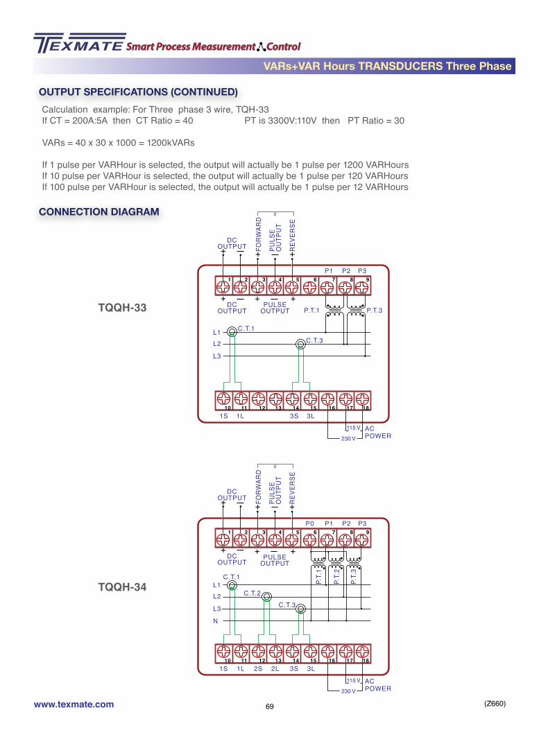
(Z660)www.texmate.com 69
CONNECTION DIAGRAM
ACPOWER230 V
115 V
L1 C.T.1
P2 P3P1
1S 1L 3S 3L
C.T.3
P.T.1 P.T.3
L2
L3
PULSEOUTPUT
+ +
+ +FORW
ARD
PULS
E O
UTPU
T
REVE
RSE
+DC
OUTPUT
DCOUTPUT
+
1 2 3 4 5 6 7 8 9
10 11 12 13 14 15 16 17 18
ACPOWER230 V
115 V
L1C.T.1
P2 P3P1P0
1S 1L 2S 2L 3S 3L
C.T.3C.T.2
P.T.
2
P.T.
1
P.T.
3
L2
L3
N
PULSEOUTPUT
+ +
+ +FORW
ARD
PULS
E O
UTPU
T
REVE
RSE
+DC
OUTPUT
DCOUTPUT
+
1 2 3 4 5 6 7 8 9
10 11 12 13 14 15 16 17 18
TQQH-33
TQQH-34
OUTPUT SPECIFICATIONS (CONTINUED)Calculation example: For Three phase 3 wire, TQH-33If CT = 200A:5A then CT Ratio = 40 PT is 3300V:110V then PT Ratio = 30
VARs = 40 x 30 x 1000 = 1200kVARs
If 1 pulse per VARHour is selected, the output will actually be 1 pulse per 1200 VARHoursIf 10 pulse per VARHour is selected, the output will actually be 1 pulse per 120 VARHoursIf 100 pulse per VARHour is selected, the output will actually be 1 pulse per 12 VARHours
VARs+VAR Hours TRANSDUCERS Three Phase

(Z660)www.texmate.com 70
Example:Product Ordering Code of TQQH-33121221
TQQH-33: Three Phase / 3Wire, 3element VARs+VAR Hours Transducer1: 120 V and 5A AC Input2: 50Hz ± 3Hz1: Reed Relay. Forward only2:10 pulses per WattHour2: 24V DC Power1: Plastic Case
ORDERING INFORMATION
3 Phase/ 3 Wire, 2 element
60Hz ± 3Hz
120 V and 5A AC
240 V and 5A ACCustom Input Range
(600V AC, 10Amps Max)
115V AC / 230V AC Power
1 pulse per VARHour
24V DC Power
10 pulses per VARHour
125 V DC Power
100 pulses per VARHour
Custom Power
Custom Output pulses per VARHour
Plastic Case DIN Rail mountCase D
Metal Case Screw mountCase B
3 Phase/ 4 Wire, 3 element
50Hz ± 3Hz
Custom 400Hz ± 3Hz
TQQH-34
2Y
TQQH-33
1
Y21
4321
3
3
Y
Y
2
2
1
1
BASE UNIT INPUTFrequencyOUTPUT POWER
Pulses perWatthour MOUNTING
21
FREQUENCY
Reed Relay. Forward only
Reed Relay. Forward and Reverse
Open Collector. Forward only
Open Collector. Forward and Reverse
VARs+VAR Hours TRANSDUCERS Three Phase

(Z660)www.texmate.com 71
MODELS OFFERED
FEATURES
AC Power Factor TRANSDUCERS Single Phase
• Uses Time Division Multiplication (TDM) for precision measurement of even distorted signals.• High accuracy ±0.5% of Rated Output (R.O.). • High immunity to external noise.• Quick and easy mounting to 35mm DIN Rail (DIN46277) or screw mounting.• Many input and output signal combinations.
GENERAL SPECIFICATIONS
Accuracy ............................. ± 0.2% R.O. Standard for 10 to 100% of rated output ± 0.1% R.O. (Special Option)
Temp. coefficient ................ ≤100ppm/ºC of span ≤60ppm/ºC for ambient temperature of 25ºC ±10ºC
Temp. range ........................ Operation temperature range -20ºC to 60ºC
Humidity range ................... Up to 95% RH non condensing.
Isolation ............................... Between Input/Output/Power/Case
Dielectric test ...................... DIN-IEC 688 2K Vrms/1 min, Between terminal to terminal 2.8K Vrms/1 min, Between terminal to terminal
Surge test ............................ DIN-IEC 255-4, ANSI C37 90a/1974 5KV(1.2x50 µs)
Insulation Resistance ........ Greater than 100 M Ω at 500V DC
Housing material ................ ABS Resin (94V-0) or metal
Mounting ............................. Screw mount metal case or Plastic DIN Rail 35mm
Auxiliary Power................... AC 115/230V ± 15%, 50/60Hz, 3VA DC 24V ± 20%(optional) 125V DC ± 20%(optional)
TPF-12 base model 1 Phase, 2 Wire – 1 Element
• Accurate measurement of the Power Factor (Cos φ) of a three phase system with balanced or unbal-anced loads.
• The output signals are isolated load independent DC mA or DC V, representing the measured value of the Power Factor (Cos φ).

(Z660)www.texmate.com 72
AC Power Factor TRANSDUCERS Single Phase
ACPOWER230 V
115 V
L1 C.T.1
P2P1
1S 1L 3S 3L
P.T.1
N
+DC
OUTPUT
DCOUTPUT
+
1 2 3 4 5 6 7 8 9
10 11 12 13 14 15 16 17 18
INPUT SPECIFICATIONS
Measuring Range ............... Power Factor Lead (capacitive) 0.5 …. 1 …. Lag (Inductive) 0.5
AC Voltage Input ................. 30 to 600V
AC Current Input................. 0 to 5A AC
Frequency ........................... 60Hz ±3Hz, 50Hz ±3Hz, 400Hz ±3Hz
Burden ................................. ≤0.2VA per current circuit, ≤0.1VA per voltage circuit.
Response Sensitivity ......... ≤0.5% of measuring range to maximum input range
Input Voltage ...................... 600V AC rms continuous Overload Capacity 1.25 times the rated input Voltage continuously. 2 times the rated input Voltage for 10 secs. 4 times the rated input Voltage for 5 secs.
Input Current ...................... 3 times the rated input current continuously. Overload Capacity 10 times the rated input current for 10 secs. 50 times the rated input current for 1 sec. 80 times the rated input current for 0.5 secs
OUTPUT SPECIFICATIONS
Output Variables ................. DCmA or DCV (Power Factor. Cos φ)
Ripple ................................... < 0.5% of rated output. Peak to Peak (maximum)
Response Time ................... < 400 milliseconds to go from 0 to 99% of output
Zero Adjustment ................. ± 5% of rated output (minimum)
Span Adjustment ................ ± 10% of rated output (minimum)
CONNECTION DIAGRAM

(Z660)www.texmate.com 73
Example:Product Ordering Code of TPF-1211212
TPF-12: Single Phase / 2Wire, 1element Power Factor Transducer1: 30V to 600V AC and 5A AC1: 60Hz ± 3Hz2: 4 to 20mA DC output1: 115VAC or 230VAC power2: Metal Case
ORDERING INFORMATION
Single Phase. 2 wire, 1element
AC Power Factor TRANSDUCERS Single Phase
60Hz ± 3Hz
30V to 600V AC and 5A ACCustom Input Range
(600V AC, 10Amps Max)
115V AC / 230V AC Power
24V DC Power
125 V DC Power
Custom Power
50Hz ± 3Hz
Custom 400Hz ± 3Hz
2Y
TPF-12
1
Y1
Y321
3
Y
2
1
BASE UNIT INPUT OUTPUT POWER MOUNTING
2
1
FREQUENCY
0 to 1mA DC output
4 to 20mA DC output
0 to 10V DC output
Custom output Range(Max 20mA DC or 10V DC)
Plastic Case C. DIN Rail mountCase D
Metal Case A. Screw mountCase B

(Z660)www.texmate.com 74
MODELS OFFERED
FEATURES
AC Power Factor TRANSDUCERS Three Phase
• Uses Time Division Multiplication (TDM) for precision measurement of even distorted signals.• High accuracy ±0.5% of Rated Output (R.O.). • High immunity to external noise.• Quick and easy mounting to 35mm DIN Rail (DIN46277) or screw mounting.• Many input and output signal combinations.
GENERAL SPECIFICATIONS
Accuracy ............................. ± 0.2% R.O. Standard for 10 to 100% of rated output ± 0.1% R.O. (Special Option)
Temp. coefficient ................ ≤100ppm/ºC of span ≤60ppm/ºC for ambient temperature of 25ºC ±10ºC
Temp. range ........................ Operation temperature range -20ºC to 60ºC
Humidity range ................... Up to 95% RH non condensing.
Isolation ............................... Between Input/Output/Power/Case
Dielectric test ...................... DIN-IEC 688 2K Vrms/1 min, Between terminal to terminal 2.8K Vrms/1 min, Between terminal to terminal
Surge test ............................ DIN-IEC 255-4, ANSI C37 90a/1974 5KV(1.2x50 µs)
Insulation Resistance ........ Greater than 100 M Ω at 500V DC
Housing material ................ ABS Resin (94V-0) or metal
Mounting ............................. Screw mount metal case or Plastic DIN Rail 35mm
Auxiliary Power................... AC 115/230V ± 15%, 50/60Hz, 3VA DC 24V ± 20%(optional) 125V DC ± 20%(optional)
TPF-33 base model 3 Phase, 3 Wire – 2 Element
TPF-34 base model 3 Phase, 4 Wire – 3 Element
• Accurate measurement of the Power Factor (Cos φ) of a three phase system with balanced or unbal-anced loads.
• The output signals are isolated load independent DC mA or DC V, representing the measured value of the Power Factor (Cos φ).

(Z660)www.texmate.com 75
AC Power Factor TRANSDUCERS Three Phase
ACPOWER230 V
115 V
L1 C.T.1
P2 P3P1
1S 1L 3S 3L
C.T.3
P.T.1 P.T.3
L2
L3
PULSEOUTPUT
+ +
+ +FOR
WAR
D
PULS
E O
UTP
UT
REV
ERSE
+DC
OUTPUT
DCOUTPUT
+
1 2 3 4 5 6 7 8 9
10 11 12 13 14 15 16 17 18
ACPOWER230 V
115 V
L1C.T.1
P2 P3P1P0
1S 1L 2S 2L 3S 3L
C.T.3C.T.2
P.T.
2
P.T.
1
P.T.
3
L2
L3
N
PULSEOUTPUT
+ +
+ +FOR
WAR
D
PULS
E O
UTP
UT
REV
ERSE
+DC
OUTPUT
DCOUTPUT
+
1 2 3 4 5 6 7 8 9
10 11 12 13 14 15 16 17 18
CONNECTION DIAGRAM
Output Variables ................. DCmA or DCV (Power Factor. Cos φ)
Ripple ................................... < 0.5% of rated output. Peak to Peak (maximum)
Response Time ................... < 400 milliseconds to go from 0 to 99% of output
Zero Adjustment ................. ± 5% of rated output (minimum)
Span Adjustment ................ ± 10% of rated output (minimum)
INPUT SPECIFICATIONS
Measuring Range ............... Power Factor Lead (capacitive) 0.5 …. 1 …. Lag (Inductive) 0.5
AC Voltage Input ................. 30 to 600V
AC Current Input................. 0 to 5A AC
Frequency ........................... 60Hz ±3Hz, 50Hz ±3Hz, 400Hz ±3Hz
Burden ................................. ≤0.2VA per current circuit, ≤0.1VA per voltage circuit.
Response Sensitivity ......... ≤0.5% of measuring range to maximum input range
Input Voltage ...................... 600V AC rms continuous Overload Capacity 1.25 times the rated input Voltage continuously. 2 times the rated input Voltage for 10 secs. 4 times the rated input Voltage for 5 secs.
Input Current ...................... 3 times the rated input current continuously. Overload Capacity 10 times the rated input current for 10 secs. 50 times the rated input current for 1 sec. 80 times the rated input current for 0.5 secs OUTPUT SPECIFICATIONS
3 Phase 3 wire 3 Phase 4 wire

(Z660)www.texmate.com 76
Example:Product Ordering Code of TPF-3311212
TPF-33: Three Phase / 3Wire, 2element Power Factor Transducer1: 30V to 600V AC and 5A AC1: 60Hz ±3Hz2: 4 to 20mA DC output1: 115VAC or 230VAC power2: Metal Case
ORDERING INFORMATION
Three Phase. 3 wire, 2element
Three Phase. 4 wire, 3element
AC Power Factor TRANSDUCERS Three Phase
60Hz ± 3Hz
30V to 600V AC and 5A ACCustom Input Range
(600V AC, 10Amps Max)
115V AC / 230V AC Power
24V DC Power
125 V DC Power
Custom Power
Plastic Case C. DIN Rail mountCase D
Metal Case A. Screw mountCase B
50Hz ± 3Hz
Custom 400Hz ± 3Hz
TPF-34
2Y
TPF-33
1
Y1
Y321
3
Y
2
1
BASE UNIT INPUT OUTPUT POWER MOUNTING
2
1
FREQUENCY
0 to 1mA DC output
4 to 20mA DC output
0 to 10V DC output
Custom output Range(Max 20mA DC or 10V DC)
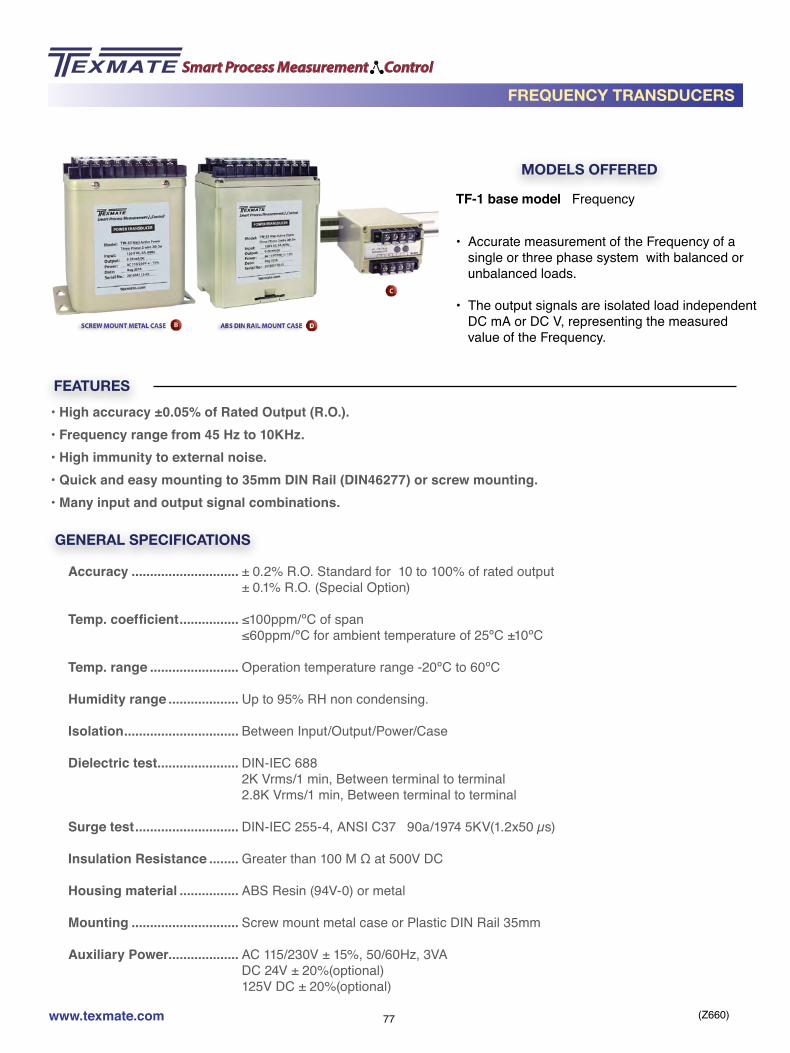
(Z660)www.texmate.com 77
MODELS OFFERED
FEATURES
FREQUENCY TRANSDUCERS
• High accuracy ±0.05% of Rated Output (R.O.). • Frequency range from 45 Hz to 10KHz. • High immunity to external noise.• Quick and easy mounting to 35mm DIN Rail (DIN46277) or screw mounting.• Many input and output signal combinations.
GENERAL SPECIFICATIONS
Accuracy ............................. ± 0.2% R.O. Standard for 10 to 100% of rated output ± 0.1% R.O. (Special Option)
Temp. coefficient ................ ≤100ppm/ºC of span ≤60ppm/ºC for ambient temperature of 25ºC ±10ºC
Temp. range ........................ Operation temperature range -20ºC to 60ºC
Humidity range ................... Up to 95% RH non condensing.
Isolation ............................... Between Input/Output/Power/Case
Dielectric test ...................... DIN-IEC 688 2K Vrms/1 min, Between terminal to terminal 2.8K Vrms/1 min, Between terminal to terminal
Surge test ............................ DIN-IEC 255-4, ANSI C37 90a/1974 5KV(1.2x50 µs)
Insulation Resistance ........ Greater than 100 M Ω at 500V DC
Housing material ................ ABS Resin (94V-0) or metal
Mounting ............................. Screw mount metal case or Plastic DIN Rail 35mm
Auxiliary Power................... AC 115/230V ± 15%, 50/60Hz, 3VA DC 24V ± 20%(optional) 125V DC ± 20%(optional)
TF-1 base model Frequency
• Accurate measurement of the Frequency of a single or three phase system with balanced or unbalanced loads.
• The output signals are isolated load independent DC mA or DC V, representing the measured value of the Frequency.

(Z660)www.texmate.com 78
+DC
OUTPUT
OUTPUT+ INPUT
+12V Auxiliary
Power for Sensor
ACPOWER230 V
115 V
1 2 3 4 5 6 7 8 9
10 11 12 13 14 15 16 17 18
CONNECTION DIAGRAM
INPUT SPECIFICATIONS
AC Voltage Input range ...... 2V to 200V AC or 30 to 600V AC
Frequency ........................... 60Hz ±3Hz, 50Hz ±3Hz, 400Hz ±3Hz
Burden ................................. ≤0.2VA per current circuit, ≤0.1VA per voltage circuit.
Response Sensitivity ......... ≤0.5% of measuring range to maximum input range
Input Voltage ....................... 600V AC rms continuous Overload Capacity 1.25 times the rated input Voltage continuously. 2 times the rated input Voltage for 10 secs. 4 times the rated input Voltage for 5 secs.
OUTPUT SPECIFICATIONS
Output Variables ................. DCmA or DCV
Ripple ................................... < 0.5% of rated output. Peak to Peak (maximum)
Response Time ................... < 400 milliseconds to go from 0 to 99% of output
Zero Adjustment ................. ± 5% of rated output (minimum)
Span Adjustment ................ ± 10% of rated output (minimum)
Load Resistance ................. 10 kΩ maximum for 0 to 1mA output 500 Ω maximum for 4 to 20mA output 500 Ω minimum for 0 to 10V output
FREQUENCY TRANSDUCERS

(Z660)www.texmate.com 79
Example:Product Ordering Code of TF-111212
TF-1: Frequency Transducer1: 30V to 600V AC and 5A AC1: 60Hz ± 3Hz2: 4 to 20mA DC output1: 115VAC or 230VAC power2: Metal Case
ORDERING INFORMATION
Frequency
55 - 65 Hz
80V AC to 600V AC
2V AC to 30V AC/DC
Custom input range
115V AC / 230V AC Power
24V DC Power
125 V DC Power
Custom Power
45 - 55 Hz
Custom (0 to 10KHz Max)
2Y
TF-1
1
2Y
1
Y321
3
Y
2
1
BASE UNIT INPUT OUTPUT POWER MOUNTING
2
1
FREQUENCY
0 to 1mA DC output
4 to 20mA DC output
0 to 10V DC output
Custom output Range(Max 20mA DC or 10V DC)
Plastic Case C. DIN Rail mountCase D
Metal Case A. Screw mountCase B
FREQUENCY TRANSDUCERS

(Z660)www.texmate.com 80
CASE DIMENSIONS
Fire Retardant, ABS Case DIN Rail Mounting
4.32
” (1
07.5
mm
)
4.95
” (1
25.7
mm
)
0.6” (15.2mm)
1.38” (35mm) Rail (DIN 46277)
3.15” (80mm)
2.36
” (6
0mm
)
Case C
Metal Case, Screw Mounting4.
09"
(104
mm
)
4.84
" (1
23m
m)
1.
50"
(38.
1mm
)
2.2
8" (5
8mm
)
4.06" (103mm)
3.50" (89mm)
3.03" (77mm)
No.8-36UNFM4 Screw
Case A
450 State Place, Escondido, CA 92029 • For ordering info call: 1-800-TEXMATE (1-800-839-6283) or 760 598-9899• Email: [email protected] • 24 Hours • Fax: (760) 598-9828 •• For tech assistance call: (760) 598-9899
Copyright © 2016 Texmate Inc. All Rights Reserved.
CASE DIMENSIONS - CASE A & C
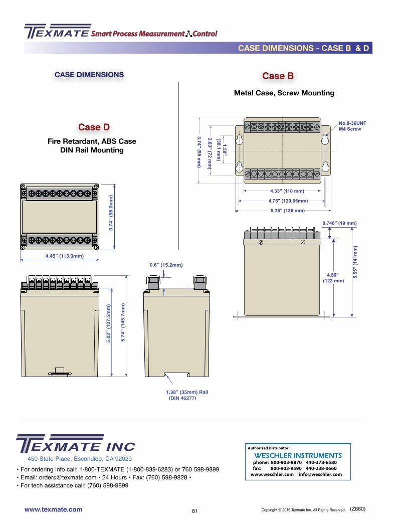
(Z660)www.texmate.com 81
CASE DIMENSIONS
Fire Retardant, ABS Case DIN Rail Mounting
Case BMetal Case, Screw Mounting
Case D
4.80" (122 mm)
0.748" (19 mm)
5.55
" (1
41m
m)
4.75" (120.65mm)
5.35" (136 mm)
4.33" (110 mm)
1.50"(38.1 m
m)
2.83" (72 mm
)
3.74" (95 mm
)
No.8-36UNFM4 Screw
3.74
” (9
5.0m
m)
4.45” (113.0mm)
5.02
” (1
27.5
mm
)
5.74
” (1
45.7
mm
)
0.6” (15.2mm)
1.38” (35mm) Rail (DIN 46277)
450 State Place, Escondido, CA 92029• For ordering info call: 1-800-TEXMATE (1-800-839-6283) or 760 598-9899• Email: [email protected] • 24 Hours • Fax: (760) 598-9828 •• For tech assistance call: (760) 598-9899
Copyright © 2016 Texmate Inc. All Rights Reserved.
CASE DIMENSIONS - CASE B & D
phone: 800-903-9870 440-378-6580 fax: 800-903-9590 440-238-0660
www.weschler.com [email protected]
WESCHLER INSTRUMENTSAuthorized Distributor: