slides of 6th lesson
TRANSCRIPT

SOEM 024: Computer Aided Design
E. Rozos

3D Design with AutoCAD 2002
– Isometric Drawings – 3D coordinates, views– Wire-frame – 3D modelling, extruding – Primitive objects– Boolean operators

Terminology• Boolean operations: Commands that allow you to add, subtract or
intersect solid objects in AutoCAD. • Complex surface: Generally a curved surface. Examples: car
fender, landscape contour. • Elevation: The difference between an object being at zero on the Z-
axis and the height that it is above zero. • Face: The simplest true 3D surface. • Facet: A three or four sided polygon that represents a piece (or
section) of a 3D surface.• Hidden line removal: A way of hiding lines that would not be visible
if you were viewing the actual object you have drawn in AutoCAD.(Command: HIDE)
• Isometric Drawing: A simple way of achieving a '3D' appearance using 2D drawing methods.
• Plan View: Also known as the top view, a plan view looks directly down the WCS Z-axis to the X-Y axis.

Terminology• Primitive: A basic solid building block (cones, cylinders)• Rendering: A complex way of adding photo-realistic qualities to a
3D model you have created. • Shading: A quick way of adding colour to a 3D object you have
drawn. (Command: SHADE) • Solid Model: A 3D model creating using solid 'building blocks'. This
is the most accurate way of representing real-world objects in CAD. • Surface Model: A 3D model defined by surfaces. The surface
consists of polygons. (See facets.) • Thickness: A property of lines and other objects that gives them a
3D like appearance. • Wire-frame Model: A 3D shape that is defined by lines and curves.
A skeletal representation. Hidden line removal is not possible with this model.
• Z-Axis: The third axis that defines the depth.

ISOMETRIC DRAWING • This is the simplest way to give a 3D representation while
using only 2D commands. This has been the usual way of doing things before CAD allowed true 3D work to be done. Many times an isometric drawing is used to compliment a 3 view orthographic drawing.
• The basic isometric drawing of the object gives a very good idea of what it looks like. If this is all that is needed then isometric works well. As soon as you change anything, like height, then you'll need to redraw all four views.
• AutoCAD has a command called ISOPLANE which allows you to easily draw at a 30 degree angle as needed for an isometric drawing. You can switch between the three 'isoplanes', by using this command or by pressing the F5 key.

Exercise 1, isometric drawing

3 Dimensions• When you entered points previously, you would
enter them in the format: X,Y. By doing this, you let AutoCAD know that in these cases, Z was equal to zero.
• Entering 4,3 would be the same as entering 4,3,0.
• Now if you drew a line from the origin (0,0,0) to a point at 4,3,2, you would get a line that goes 4 drawing units (du) to the right, 3 du up and 2 du towards you.
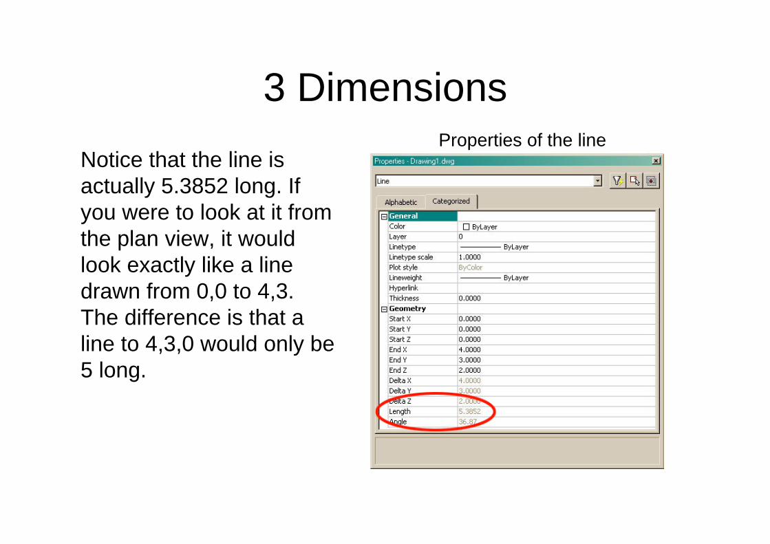
3 DimensionsProperties of the line
Notice that the line is actually 5.3852 long. If you were to look at it from the plan view, it would look exactly like a line drawn from 0,0 to 4,3. The difference is that a line to 4,3,0 would only be 5 long.

Angles in 3D• You also have to know how AutoCAD measures
angles of rotation in 3D. There is a somewhat simple rule for this called "The Right Hand Rule".
• To figure out which is the positive rotation angle, imagine that you are wrapping your right hand around the axis with your thumb pointing towards the positive end.
• The direction that your fingers are wrapped is the positive direction. This applies to all three axes.
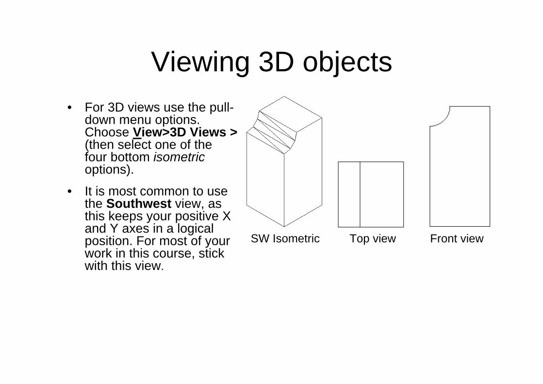
Viewing 3D objects• For 3D views use the pull-
down menu options. Choose View>3D Views >(then select one of the four bottom isometricoptions).
• It is most common to use the Southwest view, as this keeps your positive X and Y axes in a logical position. For most of your work in this course, stick with this view.
SW Isometric Top view Front view

Views and viewports• You can have viewports in
either model space or paper space. You can use one of the prefixed viewport configurations (View Viewports New Viewports)
• When you have more than one viewport, click inside the one you want active. Every view operation (zoom, pan) will be restricted to the active viewport.
• Manage and save the current viewports with the VIEW command.

Views and viewportsIn 3D design any modification to the object automatically reflects to all views.

Exercise 2, wireframe modelling

Exercise 3, line thickness

Regions and 3D surfacesWe will now begin using true 3D commands. First you will create a 2D region and then extrude it into a 3D solid.

Exercise 4, daw 3D objects

Perspective viewsPerspective view is controlled with the “DVIEW”command. The basis of generating a perspective view is to have a virtual camera and target. Think of where you would like to 'stand' (the camera) and what direction you want to look at (the target).

Exercise 5, 3D object viewing

Exercise 6, advanced extruding
Extrusion path
Extruded object
Extrusion height
Taper angle

LoftingThe loft command was introduced in AutoCad 2007. The loft command allows you to extrude several shapes and make one continuous object.
Create a lofted object from the 2 rectangles

Primitive objects

Boolean operators

Exercise 7, 3D boolean operations
UNI

Assignment 3
Design an aeroplane