slide 1 istore-1 update david patterson university of california at berkeley...
Post on 19-Dec-2015
217 views
TRANSCRIPT

Slide 1
ISTORE-1 Update
David PattersonUniversity of California at Berkeley
UC Berkeley IRAM Group UC Berkeley ISTORE Group
July 2000

Slide 2
Perspective on Post-PC Era• PostPC Era will be driven by 2 technologies:
1) “Gadgets”:Tiny Embedded or Mobile Devices–ubiquitous: in everything–e.g., successor to PDA,
cell phone, wearable computers
2) Infrastructure to Support such Devices–e.g., successor to Big Fat Web Servers, Database
Servers

Slide 3
Outline• Motivation for the ISTORE project
– AME: Availability, Maintainability, Evolutionary growth
• ISTORE’s research principles & techniques– Introspection– SON: Storage-Oriented Node In Cluster– RAIN: Redundant Array of Inexpensive Network
switches– Benchmarks for AME
• A Case for SON vs. CPUs• Applications, near term and future• Conclusions and future work

Slide 4
Lampson: Systems Challenges• Systems that work
– Meeting their specs– Always available– Adapting to changing environment– Evolving while they run– Made from unreliable components– Growing without practical limit
• Credible simulations or analysis• Writing good specs• Testing• Performance
– Understanding when it doesn’t matter
“Computer Systems Research-Past and Future”
Keynote address, 17th SOSP,
Dec. 1999Butler Lampson
Microsoft

Slide 5
Hennessy: What Should the “New World” Focus Be?• Availability
– Both appliance & service• Maintainability
– Two functions:» Enhancing availability by preventing failure» Ease of SW and HW upgrades
• Scalability– Especially of service
• Cost– per device and per service transaction
• Performance– Remains important, but its not SPECint
“Back to the Future: Time to Return to Longstanding
Problems in Computer Systems?” Keynote address,
FCRC, May 1999
John HennessyStanford

Slide 6
Is Maintenance Key?
Cause Of System Crashes
0%
10%
20%
30%
40%
50%
60%
70%
80%
90%
100%
1985 1993
Changes Over Time
Per
cen
tag
e O
f C
rash
es
Others
System Management
Software Failure
Hardware Failure
• Rule of Thumb: Cost Maintenance 10X cost of Hardware
• Causes of crashes on Digital VAX systems between 1985 and 1993. [Murp95]

Slide 7
The real scalability problems: AME
• Availability– systems should continue to meet quality of service
goals despite hardware and software failures
• Maintainability– systems should require only minimal ongoing human
administration, regardless of scale or complexity: Today, cost of maintenance = 10X cost of purchase
• Evolutionary Growth– systems should evolve gracefully in terms of
performance, maintainability, and availability as they are grown/upgraded/expanded
• These are problems at today’s scales, and will only get worse as systems grow

Slide 8
Principles for achieving AME (1)
• No single points of failure• Redundancy everywhere• Performance robustness is more
important than peak performance– “performance robustness” implies that real-world
performance is comparable to best-case performance
• Performance can be sacrificed for improvements in AME– resources should be dedicated to AME
» compare: biological systems spend > 50% of resources on maintenance
– can make up performance by scaling system

Slide 9
Principles for achieving AME (2)
• Introspection– reactive techniques to detect and adapt to
failures, workload variations, and system evolution
– proactive techniques to anticipate and avert problems before they happen

Slide 10
Hardware Techniques (1): SON• SON: Storage Oriented Nodes (in clusters)• Distribute processing with storage
– If AME really important, provide resources!– Most storage servers limited by speed of CPUs!! – Amortize sheet metal, power, cooling, network for disk
to add processor, memory, and a real network?– Embedded processors 2/3 perf, 1/10 cost, power?– Serial lines, switches also growing with Moore’s Law;
less need today to centralize vs. bus oriented systems
• Advantages of cluster organization– Truly scalable architecture– Architecture that tolerates partial failure– Automatic hardware redundancy

Slide 11
Hardware techniques (2)• Heavily instrumented hardware
– sensors for temp, vibration, humidity, power, intrusion
– helps detect environmental problems before they can affect system integrity
• Independent diagnostic processor on each node– provides remote control of power, remote console
access to the node, selection of node boot code– collects, stores, processes environmental data for
abnormalities– non-volatile “flight recorder” functionality– all diagnostic processors connected via independent
diagnostic network

Slide 12
Hardware techniques (3)• On-demand network
partitioning/isolation– Internet applications must remain available
despite failures of components, therefore can isolate a subset for preventative maintenance
– Allows testing, repair of online system– Managed by diagnostic processor and network
switches via diagnostic network

Slide 13
Hardware techniques (4)• Built-in fault injection capabilities
– Power control to individual node components– Injectable glitches into I/O and memory busses– Managed by diagnostic processor – Used for proactive hardware introspection
» automated detection of flaky components» controlled testing of error-recovery mechanisms
– Important for AME benchmarking (see next slide)

Slide 14
ISTORE-1 hardware platform• 80-node x86-based cluster, 1.4TB storage
– cluster nodes are plug-and-play, intelligent, network-attached storage “bricks”
» a single field-replaceable unit to simplify maintenance
– each node is a full x86 PC w/256MB DRAM, 18GB disk– more CPU than NAS; fewer disks/node than cluster
ISTORE Chassis80 nodes, 8 per tray2 levels of switches•20 100 Mbit/s•2 1 Gbit/sEnvironment Monitoring:UPS, redundant PS,fans, heat and vibration sensors...
Intelligent Disk “Brick”Portable PC CPU: Pentium II/266 + DRAM
Redundant NICs (4 100 Mb/s links)Diagnostic Processor
Disk
Half-height canister

Slide 15
ISTORE-1 Status• 10 Nodes manufactured; 60 board
fabbed, 25 to go• Boots OS• Diagnostic Processor Interface SW
complete• PCB backplane: not yet designed• Finish 80 node system: Summer 2000

Slide 16
A glimpse into the future?• System-on-a-chip enables computer,
memory, redundant network interfaces without significantly increasing size of disk
• ISTORE HW in 5-7 years:– building block: 2006 MicroDrive
integrated with IRAM » 9GB disk, 50 MB/sec from disk» connected via crossbar switch
– If low power, 10,000 nodes fit into one rack!
• O(10,000) scale is our ultimate design point

Slide 17
Hardware Technique (6): RAIN• Switches for ISTORE-1 substantial fraction
of space, power, cost, and just 80 nodes!• Redundant Array of Inexpensive Disks
(RAID): replace large, expensive disks by many small, inexpensive disks, saving volume, power, cost
• Redundant Array of Inexpensive Network switches: replace large, expensive switches by many small, inexpensive switches, saving volume, power, cost?– ISTORE-1: Replace 2 16-port 1-Gbit switches by fat
tree of 8 8-port switches, or 24 4-port switches?

Slide 18
“Hardware” techniques (6)• Benchmarking
– One reason for 1000X processor performance was ability to measure (vs. debate) which is better
» e.g., Which most important to improve: clock rate, clocks per instruction, or instructions executed?
– Need AME benchmarks“what gets measured gets done”“benchmarks shape a field”“quantification brings rigor”

Slide 19
Availability benchmark methodology• Goal: quantify variation in QoS metrics as
events occur that affect system availability• Leverage existing performance benchmarks
– to generate fair workloads– to measure & trace quality of service metrics
• Use fault injection to compromise system– hardware faults (disk, memory, network, power)– software faults (corrupt input, driver error returns)– maintenance events (repairs, SW/HW upgrades)
• Examine single-fault and multi-fault workloads– the availability analogues of performance micro- and
macro-benchmarks

Slide 20
Time
Per
form
ance }normal behavior
(99% conf)
injecteddisk failure
reconstruction
0
• Results are most accessible graphically– plot change in QoS metrics over time– compare to “normal” behavior?
» 99% confidence intervals calculated from no-fault runs
Benchmark Availability?Methodology for reporting
results

Slide 21
Time (minutes)0 10 20 30 40 50 60 70 80 90 100 110
80
100
120
140
160
0
1
2
Hits/sec# failures tolerated
0 10 20 30 40 50 60 70 80 90 100 110
Hit
s p
er s
eco
nd
190
195
200
205
210
215
220
#fai
lure
s t
ole
rate
d
0
1
2
Reconstruction
Reconstruction
Example single-fault result
• Compares Linux and Solaris reconstruction– Linux: minimal performance impact but longer
window of vulnerability to second fault– Solaris: large perf. impact but restores redundancy
fast
Linux
Solaris

Slide 22
Software techniques• Fully-distributed, shared-nothing code
– centralization breaks as systems scale up O(10000)
– avoids single-point-of-failure front ends
• Redundant data storage– required for high availability, simplifies self-
testing– replication at the level of application objects
» application can control consistency policy» more opportunity for data placement optimization

Slide 23
Software techniques (2)• “River” storage interfaces
– NOW Sort experience: performance heterogeneity is the norm
» e.g., disks: outer vs. inner track (1.5X), fragmentation
» e.g., processors: load (1.5-5x)
– So demand-driven delivery of data to apps» via distributed queues and graduated declustering» for apps that can handle unordered data delivery
– Automatically adapts to variations in performance of producers and consumers
– Also helps with evolutionary growth of cluster

Slide 24
Software techniques (3)• Reactive introspection
– Use statistical techniques to identify normal behavior and detect deviations from it
– Policy-driven automatic adaptation to abnormal behavior once detected
» initially, rely on human administrator to specify policy
» eventually, system learns to solve problems on its own by experimenting on isolated subsets of the nodes
•one candidate: reinforcement learning

Slide 25
Software techniques (4)• Proactive introspection
– Continuous online self-testing of HW and SW» in deployed systems!» goal is to shake out “Heisenbugs” before they’re
encountered in normal operation» needs data redundancy, node isolation, fault injection
– Techniques:» fault injection: triggering hardware and software
error handling paths to verify their integrity/existence» stress testing: push HW/SW to their limits» scrubbing: periodic restoration of potentially
“decaying” hardware or software state•self-scrubbing data structures (like MVS)•ECC scrubbing for disks and memory

Slide 26
A Case for Storage Oriented Nodes
Advantages of SON:• 1 v. 2 Networks• Physical
Repair/Maintenance • Die size vs. Clock rate,
Complexity• Silicon Die Cost ~ Area4
• Cooling ~ (Watts/chip)N • Size, Power Cost of
System v. Cost of Disks• Cluster advantages:
dependability, scalability
Advantages of CPU:• Apps don’t
parallelize, so 1 very fast CPU much better in practice than N fast CPUs
• Leverage Desktop MPU investment
• Software Maintenance: 1 Large system with several CPUs easier to install SW than several small computers

Slide 27
SON: 1 vs. 2 networks• Current computers all have LAN + Disk
interconnect (SCSI, FCAL)– LAN is improving fastest, most investment, most
features– SCSI, FCAL poor network features, improving
slowly, relatively expensive for switches, bandwidth
– Two sets of cables, wiring?
• Why not single network based on best HW/SW technology?

Slide 28
SON: Physical Repair• Heterogeneous system with server
components (CPU, backplane, memory cards, interface cards, power supplies, ...) and disk array components (disks, cables, controllers, array controllers, power supplies, ... )– Keep all components available somewhere as FRUs
• Small number of modules that is based on hot-pluggable interconnect (LAN) with Field Replacable Units: Node, Power Supplies, network cables– Replace node (disk, CPU, memory, NI) if any fail– Preventative maintenance via isolation, fault insertion
Slide 29
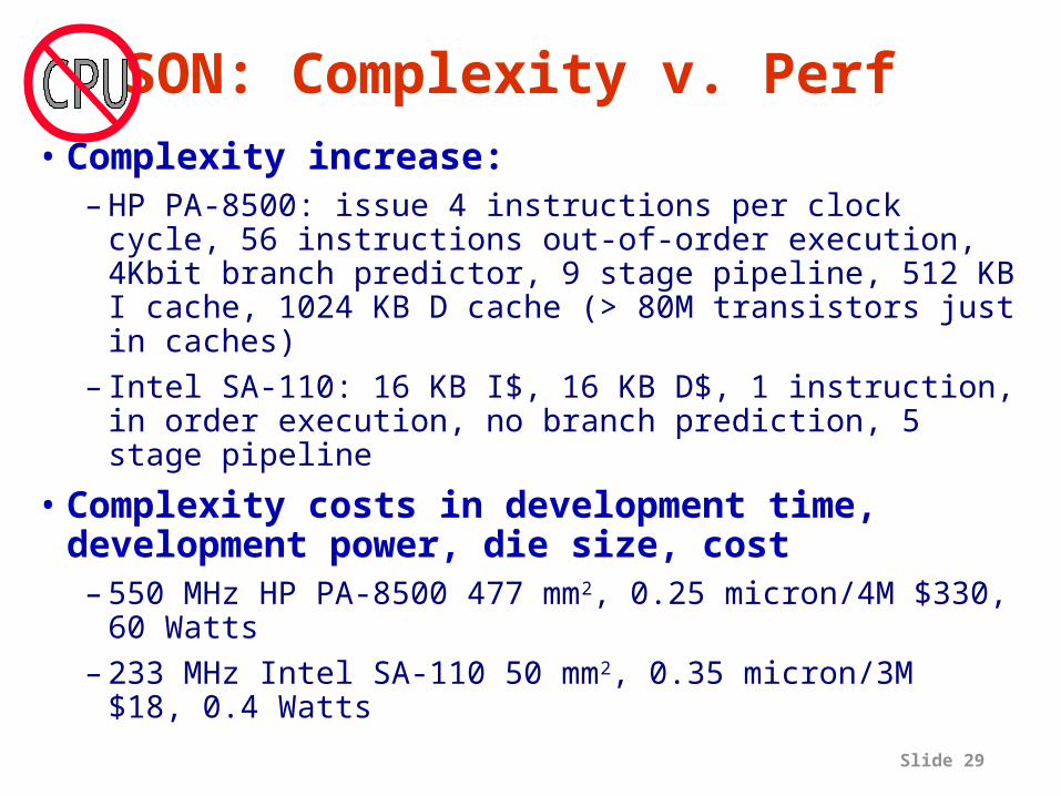
SON: Complexity v. Perf • Complexity increase:
– HP PA-8500: issue 4 instructions per clock cycle, 56 instructions out-of-order execution, 4Kbit branch predictor, 9 stage pipeline, 512 KB I cache, 1024 KB D cache (> 80M transistors just in caches)
– Intel SA-110: 16 KB I$, 16 KB D$, 1 instruction, in order execution, no branch prediction, 5 stage pipeline
• Complexity costs in development time, development power, die size, cost– 550 MHz HP PA-8500 477 mm2, 0.25 micron/4M $330,
60 Watts– 233 MHz Intel SA-110 50 mm2, 0.35 micron/3M
$18, 0.4 Watts

Slide 30
Cost of System v. Disks• Examples show cost of way we build current
systems (CPU, 2 networks, many disks/CPU …)
Date CostDisksDisks/CPU– NCR WorldMark: 10/97 $8.3M131210.2– Sun Enterprise 10k: 3/98 $5.2M66810.4– Sun Enterprise 10k: 9/99 $6.2M173227.0– IBM Netinf. Cluster: 7/00 $7.8M704055.0
• And these Data Base apps are CPU bound!!! • Also potential savings in space, power
– ISTORE-1: with big switches, its 2-3 racks for 80 CPUs/disks (3/8 rack unit per CPU/disk themselves)
– ISTORE-2: 4X density improvement?

Slide 31
SON: Cluster Advantages• Truly scalable architecture• Architecture that tolerates partial
failure• Automatic hardware redundancy

Slide 32
SON: Cooling cost v. Peak Power
• What is relationship?– Feet per second of air flow?– Packaging costs?– Fan failure?

Slide 33
The Case for CPUBut:• Assume Apps that
parallelize: WWW services, Vision, Graphics
• Leverage investment in Embedded MPU, System on a Chip
• Improved maintenance is research target: e.g., many disks lower reliability, but RAID is better
Advantages of CPU:• Apps don’t parallelize,
so N very fast CPU much better in practice than 2N fast CPUs
• Leverage Desktop MPU investment
• Software Installation: 1 Large system with several CPUs easier to keep SW up-to-date than several small computers

Slide 34
Initial Applications• ISTORE is not one super-system that
demonstrates all these techniques!– Initially provide middleware, library to support
AME goals
• Initial application targets– cluster web/email servers
» self-scrubbing data structures, online self-testing» statistical identification of normal behavior
– information retrieval for multimedia data» self-scrubbing data structures, structuring
performance-robust distributed computation

Slide 35
ISTORE Successor does Human Quality Vision?
• Malik at UCB thinks vision research at critical juncture; have about right algorithms, awaiting faster computers to test them
• 10,000 nodes with System-On-A-Chip + Microdrive + network– 1 to 10 GFLOPS/node => 10,000 to 100,000
GFLOPS– High Bandwidth Network– 1 to 10 GB of Disk Storage per Node
=> can replicate images per node– Need AME advances to keep 10,000 nodes useful

Slide 36
ISTORE Continued Funding• New NSF Information Technology
Research, larger funding (>$500K/yr)• 1400 Letters• 920 Preproposals• 134 Full Proposals Encouraged• 240 Full Proposals Submitted• 60 Funded (pending approval)• Rumor: We’re in the top 5%

Slide 37
Conclusions: ISTORE• Availability, Maintainability, and
Evolutionary growth are key challenges for server systems– more important even than performance
• ISTORE is investigating ways to bring AME to large-scale, storage-intensive servers– via clusters of network-attached, computationally-
enhanced storage nodes running distributed code– via hardware and software introspection– we are currently performing application studies to
investigate and compare techniques• Availability benchmarks a powerful tool?
– revealed undocumented design decisions affecting SW RAID availability on Linux and Windows 2000
• Exciting applications for large systems that can be maintained

Slide 38
Backup Slides

Slide 39
State of the art Cluster: NCR WorldMark
…
BYNET switched network
…
… …
bus bridge
……
1
… …scsi
……
bus bridge
64
Bus
bridge
Proc
Mem
1
ProcProcProc Mem
Bus
bridge
Proc
32
ProcProcProc
• TPC-D, TD V2, 10/97– 32 nodes x
4 200 MHz CPUs, 1 GB DRAM, 41 disks (128 cpus, 32 GB, 1312 disks, 5.4 TB)
– CPUs, DRAM, encl., boards, power
$5.3M– Disks+cntlr $2.2M– Disk shelves $0.7M
– Cables $0.1M– HW total $8.3M
scsi
scsi
scsi
scsi
scsi
Mem Mem
pci
source: www.tpc.org
pci

Slide 40
State of the Art SMP: Sun E10000
…
data crossbar switch4 address buses
…
… …
bus bridge
……
1
… …scsi
……
bus bridge
23
Mem
Xbar
bridge
Proc
s
1
ProcProcProc Mem
Xbar
bridge
Proc
s
16
ProcProcProc
• TPC-D,Oracle 8, 3/98– SMP 64 336 MHz CPUs, 64GB
dram, 668 disks (5.5TB)– Disks,shelf $2.1M– Boards,encl. $1.2M– CPUs $0.9M– DRAM $0.8M– Power $0.1M– Cables,I/O $0.1M– HW total $5.2Ms
csi
scsi
scsi
scsi
scsi
scsi
scsi
scsi
scsi source:
www.tpc.org

Slide 41
State of the Art SMP: Sun E10000
…
data crossbar switch4 address buses
…
… …
bus bridge
……
1
… …fcal
……
bus bridge
27
Mem
Xbar
bridge
Proc
s
1
ProcProcProc Mem
Xbar
bridge
Proc
s
16
ProcProcProc
• TPC-C,Oracle 8i, 9/99– SMP 64 400 MHz CPUs,
64GB dram, 1732 disks (15.5TB)
– Disks,shelf $3.6M– Boards,encl. $0.9M– CPUs $0.9M– DRAM $0.6M– Power $0.1M– Cables,I/O $0.1M
– HW total $6.2M
fcal
fcal
fcal
fcal
fcal
fcal
fcal
fcal
fcal
source: www.tpc.org

Slide 42
State of the art Cluster: IBM Netinfinity
…
Giganet 1Gbit switched Ethernet
…
… …
bus bridge
……
1
… …scsi
……
bus bridge
Bus
bridge
Proc
Mem
1
ProcProcProc Mem
Bus
bridge
Proc
32
ProcProcProc
• TPC-C, DB2, 7/00– 32 nodes x
4 700 MHz CPUs, 0.5 GB DRAM, 220 disks (128 cpus, 16 GB, 7040 disks, 116 TB)
– CPUs $0.6M– Caches $0.5M– DRAM $0.6M– Disks $3.8M– Disk shelves $1.6M– Disk cntrl. $0.4M– Racks $0.1M– Cables $0.1M– Switches $0.1M– HW total $7.8M
scsi
scsi
scsi
scsi
scsi
Mem Mem
pci
source: www.tpc.org
pci
704

Slide 43
Attacking Computer Vision• Analogy: Computer Vision Recognition in
2000 like Computer Speech Recognition in 1985– Pre 1985 community searching for good algorithms:
classic AI vs. statistics?– By 1985 reached consensus on statistics– Field focuses and makes progress, uses special
hardware– Systems become fast enough that can train
systems rather than preload information, which accelerates progress
– By 1995 speech regonition systems starting to deploy
– By 2000 widely used, available on PCs

Slide 44
Computer Vision at Berkeley• Jitendra Malik believes has an approach
that is very promising• 2 step process:
1) Segmentation: Divide image into regions of coherent color, texture and motion2) Recognition: combine regions and search image database to find a match
• Algorithms for 1) work well, just slowly (300 seconds per image using PC)
• Algorithms for 2) being tested this summer using hundreds of PCs; will determine accuracy

Slide 45
Human Quality Computer Vision
• Suppose Algorithms Work: What would it take to match Human Vision?
• At 30 images per second: segmentation– Convolution and Vector-Matrix Multiply of Sparse
Matrices (10,000 x 10,000, 10% nonzero/row)– 32-bit Floating Point– 300 seconds on PC (assuming 333 MFLOPS)
=> 100G FL Ops/image– 30 Hz => 3000 GFLOPs machine to do
segmentation

Slide 46
Human Quality Computer Vision
• At 1 / second: object recognition– Human can remember 10,000 to 100,000 objects per
category (e.g., 10k faces, 10k Chinese characters, high school vocabulary of 50k words, ..)
– To recognize a 3D object, need ~10 2D views– 100 x 100 x 8 bit (or fewer bits) per view
=> 10,000 x 10 x 100 x 100 bytes or 109 bytes– Pruning using color and texture and by organizing
shapes into an index reduce shape matches to 1000– Compare 1000 candidate merged regions with 1000
candidate object images– If 10 hours on PC (333 MFLOPS) => 12000 GFLOPS– Use storage to reduce computation?