sistemas de manipulación smc manipuladores cartesianos · dimensionamiento y selección de todos...
TRANSCRIPT
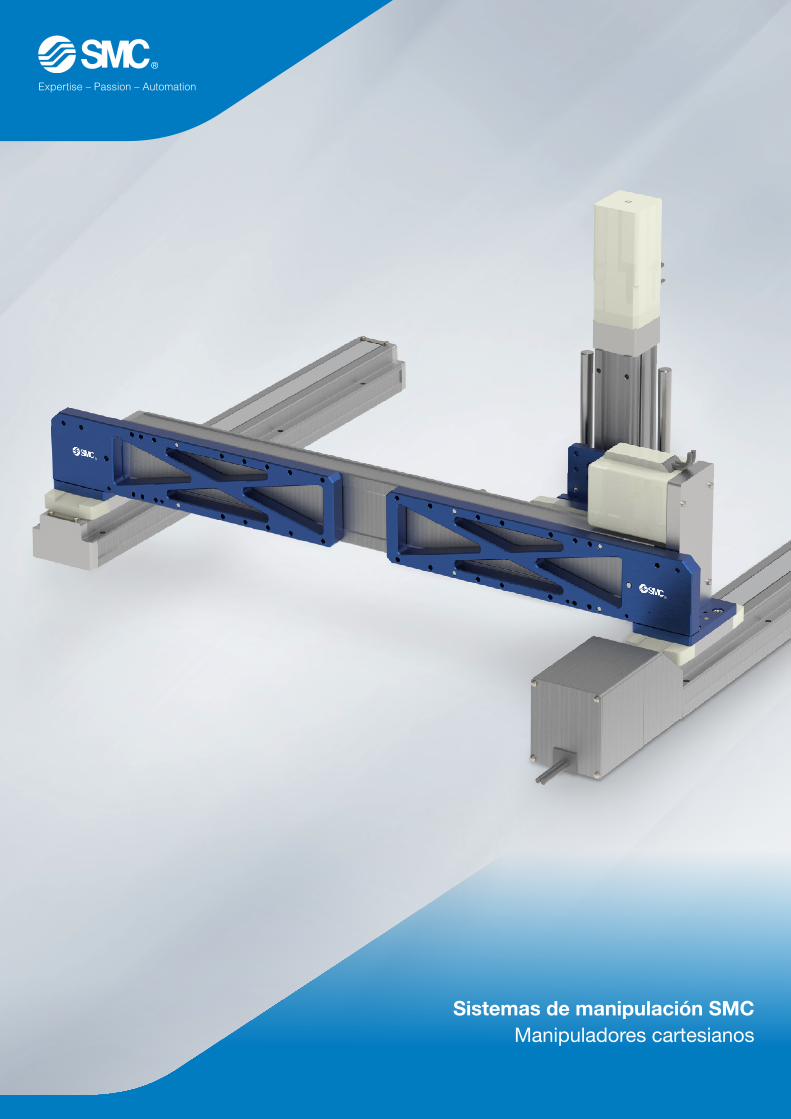
Sistemas de manipulación SMCManipuladores cartesianos

2
Sistemas de manipulación SMC
3
Flexibilidad total en el control de movimiento
Nuestro objetivo: ofrecer la solución que mejor se adapte a tus necesidades.
La solución flexible para tu aplicación
Los actuadores eléctricos, por definición, son una solución que ofrece flexibilidad en el control del movimiento. Es precisamente esta flexibilidad la esencia de nuestra gama de producto, donde puedes decidir que solución es la que mejor satisface tus necesidades.
En SMC somos conscientes de que cada cliente y cada aplicación requieren soluciones específicas. En ocasiones nuestros clientes buscan los actuadores y accesorios necesarios para diseñar y fabricar su propia solución. Otras, en cambio, requieren asesoramiento de nuestros especialistas en el diseño, dimensionamiento y selección de todos
los materiales necesarios (actuadores, pinzas, ventosas ...etc) para su aplicación.
Eficiencia y flexibilidad máximas SMC ofrece soluciones a medida para cada aplicación. En las siguientes páginas mostramos algunas de las posibles combinaciones cartesianas así como los accesorios (placas de conexión...etc) necesarios para el montaje de tu sistema de manipulación.
Ventajas de los actuadores de SMC:• Diseño compacto que permite ahorrar
espacio de instalación.
• Sistema eléctrico que proporciona el más alto nivel de precisión de repetición.
• Múltiples opciones de control de velocidad, fuerza y posición para cualquier tipo de movimiento.
• Facilidad de configuración, programa-ción y rápida puesta en marcha.
• Control en tiempo real mediante el controlador con conexión directa a bus de campo (EtherNet/IP, EtherCAT, PROFINET, DeviceNet) y ahora también con IO-Link.
4
Índice
Sistemas de manipulación SMC Ejemplos de aplicación
5-7
Selección de ejes para sistemas de manipulación:Actuadores de las series LEYG, LEFS y LEFB
8-9
Placas de unión/adaptaciónKits de montaje completos
10-11
Controladores para actuadores SMC 12
Guía para el diseño de cadenas portacables 13
Dimensiones de los sistemas de manipulación de SMC 14-19
Diseña tu aplicación:Checklist - toma de datos
20-21
Sistemas de manipulación
Precauciones:u Los clientes asumen la responsabilidad del diseño del sistema de manipulación si lo llevan a cabo ellos mismos. Te recomendamos diseñar los sistemas
de manipulación con ayuda de uno de nuestros ingenieros de aplicaciones.
u Este catálogo no sustituye a la información específica sobre el uso previsto o la información de seguridad de los componentes estándar individuales. Ten en cuenta las referencias a los catálogos de los componentes estándar relevantes.
u Reservado el derecho a realizar cambios técnicos.
5
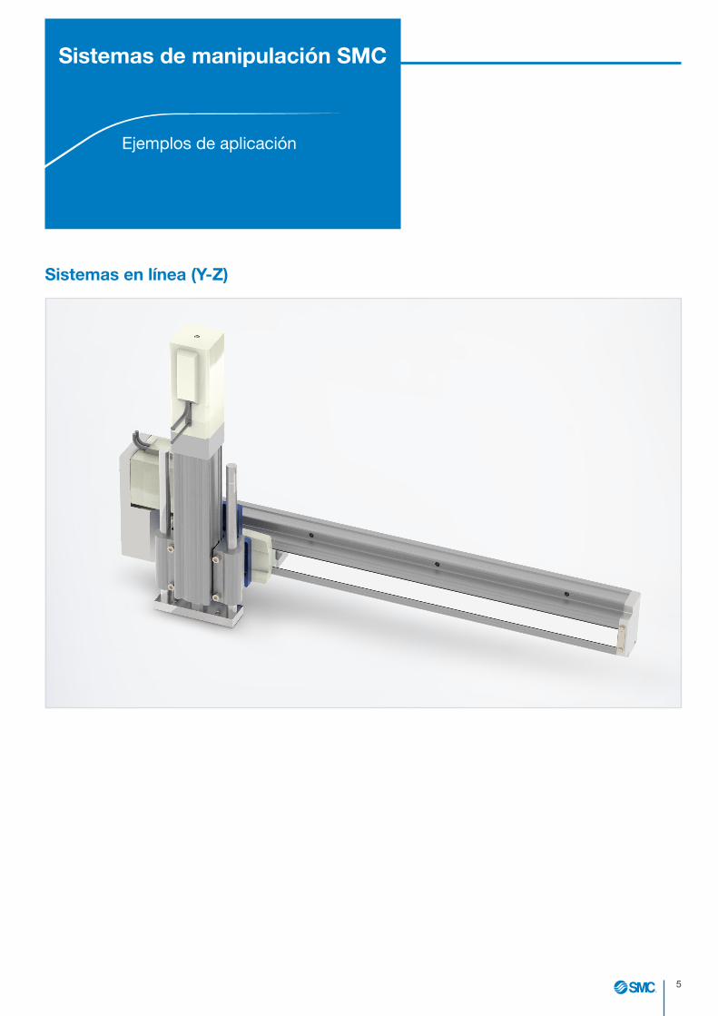
Sistemas en línea (Y-Z)
Sistemas de manipulación SMC
Ejemplos de aplicación

6
Sistemas bidimensionales (X-Y)
Guía pasiva opcional
7
Sistemas de manipulación SMCEjemplos de aplicación
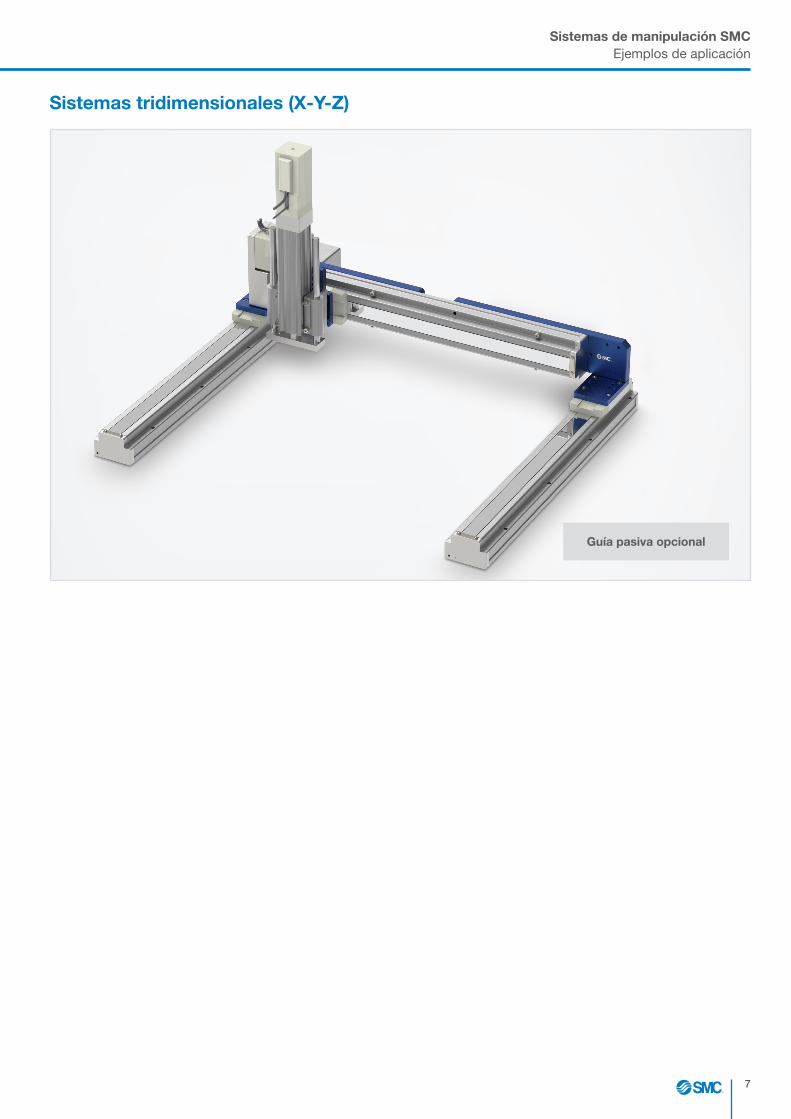
Sistemas tridimensionales (X-Y-Z)
Guía pasiva opcional
8
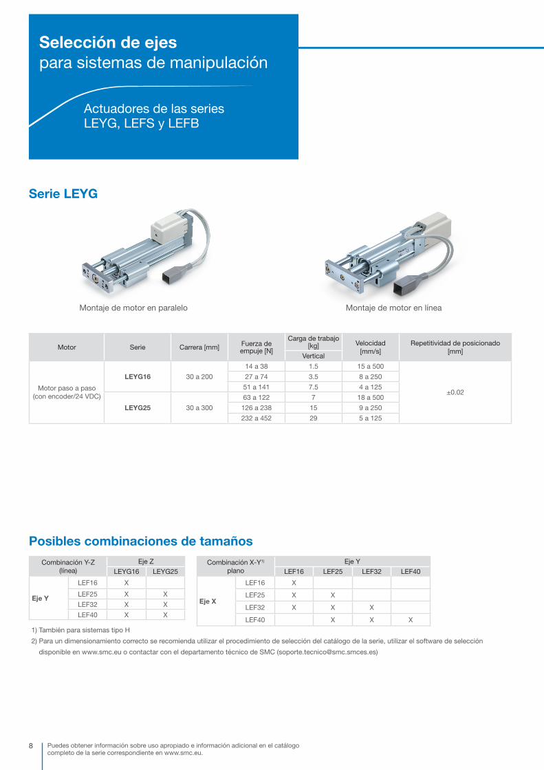
Serie LEYG
Motor Serie Carrera [mm] Fuerza de empuje [N]
Carga de trabajo [kg] Velocidad
[mm/s]Repetitividad de posicionado
[mm]Vertical
Motor paso a paso(con encoder/24 VDC)
LEYG16 30 a 200
14 a 38 1.5 15 a 500
±0.02
27 a 74 3.5 8 a 250
51 a 141 7.5 4 a 125
LEYG25 30 a 300
63 a 122 7 18 a 500
126 a 238 15 9 a 250
232 a 452 29 5 a 125
Puedes obtener información sobre uso apropiado e información adicional en el catálogo completo de la serie correspondiente en www.smc.eu.
Posibles combinaciones de tamaños
Combinación Y-Z (línea)
Eje Z
LEYG16 LEYG25
Eje Y
LEF16 X
LEF25 X X
LEF32 X X
LEF40 X X
Combinación X-Y1) plano
Eje Y
LEF16 LEF25 LEF32 LEF40
Eje X
LEF16 X
LEF25 X X
LEF32 X X X
LEF40 X X X
1) También para sistemas tipo H
2) Para un dimensionamiento correcto se recomienda utilizar el procedimiento de selección del catálogo de la serie, utilizar el software de selección
disponible en www.smc.eu o contactar con el departamento técnico de SMC ([email protected])
Selección de ejes para sistemas de manipulación
Actuadores de las series LEYG, LEFS y LEFB
Montaje de motor en paralelo Montaje de motor en línea

9
Selección de ejesActuadores de las series LEYG, LEFS y LEFB
Serie LEF
LEFS accionamiento por husillo a bolas LEFB accionamiento por correa
LEFG guía pasiva
Accionamiento Motor Serie Carrera [mm]Carga de trabajo
[kg] Velocidad [mm/s] 1) Repetitividad de posicionamiento [mm]
Horizontal
Accionamiento por husillo a bolas
Motor paso a paso (con encoder/
24 VDC)
LEFS16 50 a 50014 10 a 700
±0.0215 5 a 360
LEFS25 50 a 800
12 20 a 1100 ±0.02
25 12 a 750 ±0.02
30 6 a 400
LEFS32 50 a 1000
20 24 a 1200 ±0.02
45 16 a 800±0.02
50 8 a 520
LEFS40 150 a 1200
25 30 a 1200 ±0.02
55 20 a 1000 ±0.02
65 10 a 300
Accionamiento por correa
Motor paso a paso (con encoder/
24 VDC)
LEFB16 300 a 1000 1 48 a 1100
±0.08LEFB25300 a 2000
10 48 a 1400
LEFB32 19 48 a 1500
1) El valor máximo depende del rango de carrera
2) Para un dimensionamiento correcto se recomienda utilizar el procedimiento de selección del catálogo de la serie, utilizar el software de selección
disponible en www.smc.eu o contactar con el departamento técnico de SMC ([email protected])
Diseño Serie Carrera [mm]
Accionamiento por husillo a bolas
LEFG16-S 50 a 500
LEFG25-S 50 a 800
LEFG32-S 50 a 1000
LEFG40-S 150 a 1200
Accionamiento por correa
LEFG16-BT 300 a 1000
LEFG25-BT300 a 2000
LEFG32-BT
Serie LEFG

10
Placas de unión/adaptaciónKits de montaje completos
Realiza el pedido del kit de montaje adecuado para tu sistema de manipulación SMC. Los kits de montaje suministrados contienen los elementos necesarios incluidos los tornillos y pasadores, así como las instrucciones de instalación.
1) La guía solo es posible para los pórticos bidimensionales y tridimensionales2) Compatibilidad de elementos de montaje para cadenas portacables de la empresa IGUS GmbH (ver página 13)3) Los sistemas en línea (pieza Y+ Z) no se pueden diseñar con fijación de cadenas portacables4) Kit de montaje para LEYG25 de carrera <40 mm bajo pedido
Referencias de los kits de montaje completos para sistemas de manipulación SMCDependiendo del tipo de sistema, especifica únicamente las piezas del código requerido.
Sistema en línea (piezas Y + Z)
Sistema bidimensional (piezas X + Y)
Sistema tridimensional (piezas X + Y + Z)
Tamaño
16
25
32
40
Tamaño
16
25
32
40
Tamaño
16
25 4)
Guía1)
– Ninguno
HGuía de apoyo
Piezas de conexión
– Ninguno
1Fijación de cadena
portacables2) 3)
EA - LEF X 16 - LEF Y 16 - LEYG Z 16 - H 1
Ejemplo de referencia de kit para un sistema bidimensional con elementos de fijación para cadenas portacables:
EA - LEFX25 - LEFY16 - 1
Pieza X Pieza Y Pieza Z

11
Placas de unión/adaptaciónKits de montaje
Detalle de los componentes de los kit montajeSi deseas pedir los elementos de montaje de forma individual, aquí puedes encontrar las referencias para las combinaciones de actuadores correspondientes.
Los elementos de montaje suministrados contienen los tornillos y pasadores necesarios, así como las instrucciones de instalación.
Combinación X-Y1) Eje Y
LEF16 LEF25 LEF32 LEF40
Eje X
LEF16EA-LEF-X16EA-LEF-Y16
LEF25EA-LEF-X25EA-LEF-Y16
EA-LEF-X25EA-LEF-Y25
LEF32EA-LEF-X32EA-LEF-Y16
EA-LEF-X32EA-LEF-Y25
EA-LEF-X32EA-LEF-Y32
LEF40EA-LEF-X40EA-LEF-Y25
EA-LEF-X40EA-LEF-Y32
EA-LEF-X40EA-LEF-Y40
1) Necesitas 2 unidades de cada uno de los elementos de montaje enumerados para los sistemas en H
Combinación X-Y Eje Z
LEYG16 LEYG251)
Eje Y
LEF16 EA-LEYG-Z16
LEF25EA-LEF-X25
EA-LEYG-Z16EA-LEF-X25
EA-LEYG-Z25
LEF32EA-LEF-X32
EA-LEYG-Z16EA-LEF-X32
EA-LEYG-Z25
LEF40EA-LEF-X40
EA-LEYG-Z16EA-LEF-X40
EA-LEYG-Z25
1) Elemento de montaje para eje Z de serie LEYG25 con carrera <40 mm bajo pedido
Ejemplo:EA-LEF-Y25EA-LEF-X32
E
F
D
C
B
A
1 2 3 465
7 8
1 2 3 47
5 68
E
F
D
C
B
A
®PROJEKTIONS- METHODE 1
SMC GermanTechnical Centre
SIZE:A3ALL DIMSIN MMEGELSBACH, GERMANY REV. CHANGE NOTE MODIFICATION NAME DATE
MATERIAL/FINISH DRAWN KAISER PRODUCT PART NUMBER
CEV50039-A-060MATERIAL:
DATE 13.03.18DESIGNED DESCRIPTION
KatalogSURFACE: DATE
CHECKED TRACKING NUMBERSCALE
1:2FINISH:
DATEAPPROVED DOCUMENT NUMBER
REVISION SHEETCEV50039-A-060 0 1 of 1DATE© The reproduction, distribution and utilization of this document as well as the communication of it's contents to others without express authorization is
prohibited. Offenders will be held liable for thepayment of damages. All rights reserved in the event of the grant of a patent, utility model or design. CUSTOMER
REMOVE ALL BURRSAND SHARP EDGES
Rz 12,5
THREADS TO 6g/6HTHD LENGTHS +1.00/-0
2400020001.2200010000.810004000.54001200.3120300.23060.1630.130.5TOLUP TOOVER
GENERAL TOLERANCESISO 2768-mK (MEDIUM)LINEAR TOLERANCES
TOLERANCE PRINCIPLESTO ISO 8015
"Unless otherwise noted along with a separate contract or agreement within the Product Specifications, the safty instructions
specified in the product catalog are applied. Please contact your local SMC Sales office for further details."
Ausleger rechts montiert
Ausleger links montiert
Ejemplo:EA-LEF-X25EA-LEYG-Z16
E
F
D
C
B
A
1 2 3 465
7 8
1 2 3 47
5 68
E
F
D
C
B
A
®PROJEKTIONS- METHODE 1
1_5 1_6 1_81_10 1_122_5 2_6 2_82_10 2_123_5 3_6 3_83_10 3_124_5 4_6 4_84_10 4_12SMC German
Technical CenterSIZE:A3 5_5 5_6 5_8
5_10 5_12ALL DIMSIN MM
6_5 6_6 6_86_10 6_12
EGELSBACH, GERMANY REV. CHANGE NOTE MODIFICATION NAME DATEMATERIAL/FINISH DRAWN 8_5 PRODUCT PART NUMBER
9_7MATERIAL:
DATE 10_5
10_1 DESIGNED 11_5 DESCRIPTION
12_7SURFACE: DATE 13_5
- CHECKED 14_5 TRACKING NUMBERSCALE
1:1FINISH:
DATE 16_5
- APPROVED 17_5 DOCUMENT NUMBERREVISION SHEET18_7 18_11 1 of 1
DATE 19_5© The reproduction, distribution and utilization of this document as well as the communication of it's contents to others without express authorization is
prohibited. Offenders will be held liable for thepayment of damages. All rights reserved in the event of the grant of a patent, utility model or design. CUSTOMER 20_11
REMOVE ALL BURRSAND SHARP EDGES
Rz 12,5
THREADS TO 6g/6HTHD LENGTHS +1.00/-0
2400020001.2200010000.810004000.54001200.3120300.23060.1630.130.5TOLUP TOOVER
GENERAL TOLERANCESISO 2768-mK (MEDIUM)LINEAR TOLERANCES
TOLERANCE PRINCIPLESTO ISO 8015
"Unless otherwise noted along with a separate contract or agreement within the Product Specifications, the safty instructions
specified in the product catalog are applied. Please contact your local SMC Sales office for further details."

12
Controladores para actuadores SMC
Controlador del motor paso a paso – Serie JXC91/E1/P1/D1/L1
u Compatible con actuadores de las series LEF, LEY/LEYG, LES, LEP, LER, LEH, LEL, LEM
u Comunicación directa cen bus de campo con una elevada velocidad de transferencia (10/100 Mbps)
u La disponibilidad de doble puerto (IN y OUT) permite construir topologías lineales y DLR:- Menos cableado- Soporta la comunicación en anillo o redundante (DLR, MRP)
u Parametrización usando software o teaching box
JXCE1 JXCD1 JXCL1JXCP1
Controlador de motor paso a paso de 3 o 4 ejes – Serie JXC73/83/92/93
u Compatible con actuadores de las series LEF, LEY/LEYG, LES, LEP, LER, LEH
u Entrada de datos de paso con un máx. de 2048 posiciones:– Instrucciones de coordenadas para posición absoluta/relativa- Operación de posicionamiento/empuje
u Interpolación lineal y circular
u Control simultáneo de 3 ejes /4 ejes
u Parametrización a través de software
JXC73/83Diseño de I/O en paralelo
JXC93JXC92
Puedes obtener información sobre uso apropiado e información adicional en el catálogocompleto de la serie correspondiente en www.smc.eu.
JXC91
13
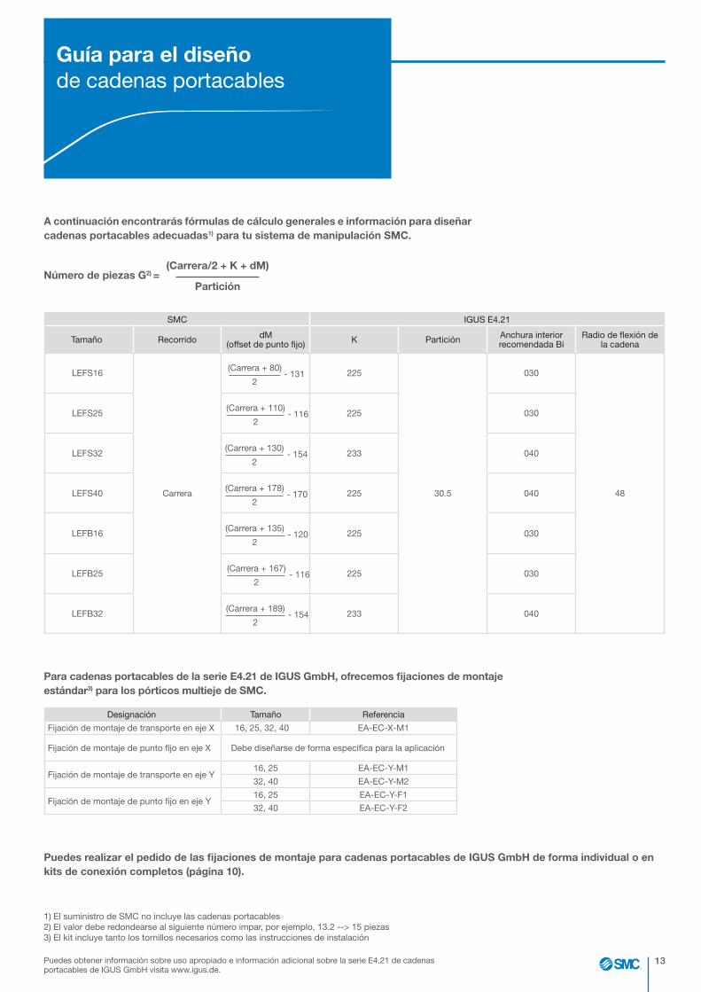
Guía para el diseñode cadenas portacables
Puedes obtener información sobre uso apropiado e información adicional sobre la serie E4.21 de cadenas portacables de IGUS GmbH visita www.igus.de.
A continuación encontrarás fórmulas de cálculo generales e información para diseñar cadenas portacables adecuadas1) para tu sistema de manipulación SMC.
Para cadenas portacables de la serie E4.21 de IGUS GmbH, ofrecemos fijaciones de montaje estándar3) para los pórticos multieje de SMC.
Puedes realizar el pedido de las fijaciones de montaje para cadenas portacables de IGUS GmbH de forma individual o en kits de conexión completos (página 10).
1) El suministro de SMC no incluye las cadenas portacables2) El valor debe redondearse al siguiente número impar, por ejemplo, 13.2 --> 15 piezas3) El kit incluye tanto los tornillos necesarios como las instrucciones de instalación
Número de piezas G2) =(Carrera/2 + K + dM)
Partición
SMC IGUS E4.21
Tamaño Recorrido dM (offset de punto fijo) K Partición Anchura interior
recomendada BiRadio de flexión de
la cadena
LEFS16
Carrera
225
30.5
030
48
LEFS25 225 030
LEFS32 233 040
LEFS40 225 040
LEFB16 225 030
LEFB25 225 030
LEFB32 233 040
- 154(Carrera + 130)
2
- 131(Carrera + 80)
2
- 116(Carrera + 110)
2
- 170(Carrera + 178)
2
- 120(Carrera + 135)
2
- 116(Carrera + 167)
2
- 154(Carrera + 189)
2
Designación Tamaño Referencia
Fijación de montaje de transporte en eje X 16, 25, 32, 40 EA-EC-X-M1
Fijación de montaje de punto fijo en eje X Debe diseñarse de forma específica para la aplicación
Fijación de montaje de transporte en eje Y16, 25 EA-EC-Y-M1
32, 40 EA-EC-Y-M2
Fijación de montaje de punto fijo en eje Y16, 25 EA-EC-Y-F1
32, 40 EA-EC-Y-F2

14
DimensionesSistemas en línea (Y-Z)
P
O
N
M
L
K
J
I
H
G
F
E
D
C
B
A
1 2 3 4 5 76 8 9 10 11 12 13 14 15 16 17 18 19 20 2221 23 24
16 17 18 19 20 2221 23 241 2 3 4 5 76 8 9 10 11 12 13 14 15
P
O
N
M
L
K
J
I
H
G
F
E
D
C
B
A
®PROJEKTIONS- METHODE 1
SMC GermanTechnical Center
SIZE:A0
ALL DIMSIN MMEGELSBACH, GERMANY REV. CHANGE NOTE MODIFICATION NAME DATE
MATERIAL/FINISH DRAWN KAISER PRODUCT PART NUMBER
CEV50039-A-070MATERIAL:
DATE 27.04.18
DESIGNED KAISER DESCRIPTION
Gesamtzeichnung_KatalogSURFACE: DATE 30.04.18
CHECKED 14_5 TRACKING NUMBER SCALE
AH
ub
(Z)
Hub(Y)
AA(A)
AA(P)
G
K
MB
(A)M
B(P
)
MH
(P)
MH
(A)
L(P)
L(A)
L(P) L(A)
MH
(P)
MH
(A)
MH(A)
MH(P)
G
XX
Z
L(P)
L(A)
MB
(P)
MB
(A)
XY
Hub(Y)LX
Hu
b(X
)
XX
Z
LX Hub(Y)
Hu
b(X
)
Z
XX
Hub(Y)
Hu
b(Z
)
J
AA(A)
L(A)
G
XX
Z
XY
KM
B(A
)MB
(P)
AA(P)
L(P)
MH
(P)
MH
(A)
PB
(Y)
L(P)
L(A)
MB(A)
MB(P)
Z B(Y)
Z B(Y)
MB(A)
MB(P)
PB
(Y)
J
33:100FINISH:
DATE 16_5
APPROVED 17_5 DOCUMENT NUMBER REVISION SHEET
CEV50039-A-070 0 1 of 1DATE 19_5
© The reproduction, distribution and utilization of this document as well as the communication of its contents to others without express authorization is prohibited. Offenders will be held liable for thepayment of damages. All rights reserved in the event of the grant of a patent, utility model or design. CUSTOMER
REMOVE ALL BURRSAND SHARP EDGES
Rz 12,5
THREADS TO 6g/6HTHD LENGTHS +1.00/-0
2400020001.2200010000.810004000.54001200.3120300.23060.1630.130.5
TOLUP TOOVER
GENERAL TOLERANCESISO 2768-mK (MEDIUM)
LINEAR TOLERANCES
TOLERANCE PRINCIPLESTO ISO 8015
"Unless otherwise noted along with a separate contract or agreement within the Product Specifications, the safty instructions specified in the product catalog are applied. Please contact your local SMC Sales office for further details."
In der Zeichnung werden die Motoren mit Abdeckung dargestelltDie Bezeichnung (A) bzw. (P) steht für axiale oder parallele MotorausführungDie Bezeichnung (X),(Y) bzw. (Z) zeigt die referenzierte Achse
Stützachse (optional)
Arbeitsraum
axiale Motorausführung
parallele Motorausführung
Ansicht von Oben
Arbeitsraum
Stützachse (optional)
Ansicht von Oben
parallele Motorausführung
axiale Motorausführung
In der Zeichnung werden die Motoren mit Abdeckung dargestelltDie Bezeichnung (A) bzw. (P) steht für axiale oder parallele MotorausführungDie Bezeichnung (X),(Y) bzw. (Z) zeigt die referenzierte Achse
Flächenportal (X-Y-Portal)
Ansicht von Oben
axiale Motorausführung
parallele Motorausführung
EA-LEF-X__(entfällt bei Montage auf
Achse Baugröße 16)
EA-LEF-Z__
Ansicht von Links
Linienportal (Y-Z-Portal)
Y-Achse
Z-Achse
Ansicht von Vorne
Arbeitsraum
axiale Motorausführung
parallele Motorausführung
In der Zeichnung werden die Motoren mit Abdeckung dargestelltDie Bezeichnung (A) bzw. (P) steht für axiale oder parallele MotorausführungDie Bezeichnung (X),(Y) bzw. (Z) zeigt die referenzierte Achse
parallele Motorausführung
axiale Motorausführung
X-Achse
Y-Achse
Raumportal (X-Y-Z-Portal)
EA-LEF-Y__
EA-LEF-X__
Ansicht von Links
Ansicht von Vorne
Y-Achse
Arbeitsraum
parallele Motorausführung
axiale Motorausführung
Z-Achse
Ansicht von Vorne
X-Achse
EA-LEF-Z__
EA-LEF-X__
EA-LEF-Z__
EA-LEF-X__(entfällt bei Montage auf
Achse Baugröße 16)
axialeMotorausführung
paralleleMotorausführung
Ansicht von Links
P
O
N
M
L
K
J
I
H
G
F
E
D
C
B
A
1 2 3 4 5 76 8 9 10 11 12 13 14 15 16 17 18 19 20 2221 23 24
16 17 18 19 20 2221 23 241 2 3 4 5 76 8 9 10 11 12 13 14 15
P
O
N
M
L
K
J
I
H
G
F
E
D
C
B
A
®PROJEKTIONS- METHODE 1
SMC GermanTechnical Center
SIZE:A0
ALL DIMSIN MMEGELSBACH, GERMANY REV. CHANGE NOTE MODIFICATION NAME DATE
MATERIAL/FINISH DRAWN KAISER PRODUCT PART NUMBER
CEV50039-A-070MATERIAL:
DATE 27.04.18
DESIGNED KAISER DESCRIPTION
Gesamtzeichnung_KatalogSURFACE: DATE 30.04.18
CHECKED 14_5 TRACKING NUMBER SCALE
AH
ub
(Z)
Hub(Y)
AA(A)
AA(P)
G
K
MB
(A)M
B(P
)
MH
(P)
MH
(A)
L(P)
L(A)
L(P) L(A)
MH
(P)
MH
(A)
MH(A)
MH(P)
G
XX
Z
L(P)
L(A)
MB
(P)
MB
(A)
XY
Hub(Y)LX
Hu
b(X
)
XX
Z
LX Hub(Y)
Hu
b(X
)
Z
XX
Hub(Y)
Hu
b(Z
)
J
AA(A)
L(A)
G
XX
Z
XY
KM
B(A
)MB
(P)
AA(P)
L(P)
MH
(P)
MH
(A)
PB
(Y)
L(P)
L(A)
MB(A)
MB(P)
Z B(Y)
Z B(Y)
MB(A)
MB(P)
PB
(Y)
J
33:100FINISH:
DATE 16_5
APPROVED 17_5 DOCUMENT NUMBER REVISION SHEET
CEV50039-A-070 0 1 of 1DATE 19_5
© The reproduction, distribution and utilization of this document as well as the communication of its contents to others without express authorization is prohibited. Offenders will be held liable for thepayment of damages. All rights reserved in the event of the grant of a patent, utility model or design. CUSTOMER
REMOVE ALL BURRSAND SHARP EDGES
Rz 12,5
THREADS TO 6g/6HTHD LENGTHS +1.00/-0
2400020001.2200010000.810004000.54001200.3120300.23060.1630.130.5
TOLUP TOOVER
GENERAL TOLERANCESISO 2768-mK (MEDIUM)
LINEAR TOLERANCES
TOLERANCE PRINCIPLESTO ISO 8015
"Unless otherwise noted along with a separate contract or agreement within the Product Specifications, the safty instructions specified in the product catalog are applied. Please contact your local SMC Sales office for further details."
In der Zeichnung werden die Motoren mit Abdeckung dargestelltDie Bezeichnung (A) bzw. (P) steht für axiale oder parallele MotorausführungDie Bezeichnung (X),(Y) bzw. (Z) zeigt die referenzierte Achse
Stützachse (optional)
Arbeitsraum
axiale Motorausführung
parallele Motorausführung
Ansicht von Oben
Arbeitsraum
Stützachse (optional)
Ansicht von Oben
parallele Motorausführung
axiale Motorausführung
In der Zeichnung werden die Motoren mit Abdeckung dargestelltDie Bezeichnung (A) bzw. (P) steht für axiale oder parallele MotorausführungDie Bezeichnung (X),(Y) bzw. (Z) zeigt die referenzierte Achse
Flächenportal (X-Y-Portal)
Ansicht von Oben
axiale Motorausführung
parallele Motorausführung
EA-LEF-X__(entfällt bei Montage auf
Achse Baugröße 16)
EA-LEF-Z__
Ansicht von Links
Linienportal (Y-Z-Portal)
Y-Achse
Z-Achse
Ansicht von Vorne
Arbeitsraum
axiale Motorausführung
parallele Motorausführung
In der Zeichnung werden die Motoren mit Abdeckung dargestelltDie Bezeichnung (A) bzw. (P) steht für axiale oder parallele MotorausführungDie Bezeichnung (X),(Y) bzw. (Z) zeigt die referenzierte Achse
parallele Motorausführung
axiale Motorausführung
X-Achse
Y-Achse
Raumportal (X-Y-Z-Portal)
EA-LEF-Y__
EA-LEF-X__
Ansicht von Links
Ansicht von Vorne
Y-Achse
Arbeitsraum
parallele Motorausführung
axiale Motorausführung
Z-Achse
Ansicht von Vorne
X-Achse
EA-LEF-Z__
EA-LEF-X__
EA-LEF-Z__
EA-LEF-X__(entfällt bei Montage auf
Achse Baugröße 16)
axialeMotorausführung
paralleleMotorausführung
Ansicht von Links
u La uniformidad de la superficie de instalación puede desviarse un máximo de 0.1 mm.
u El esquema muestra los motores con cubiertas.
u Las designaciones (A) y (P) corresponden al diseño de motor axial o paralelo, respectivamente.
u Las designaciones (X), (Y) y (Z) indican los ejes de referencia.
u Puedes obtener los tamaños de conexión de los actuadores individuales e información adicional en el catálogo completo de la serie correspondiente en www.smc.eu.
Montaje de motor en línea
Montaje de motor en paraleloEje Z
Eje Y
(no aplicable al tamaño de montaje 16)Montaje de motor en paralelo
Montaje de motor en línea
Car
rera
(Z)
Espacio de trabajo
Carrera (Y)

15
DimensionesSistema en línea (Y-Z)
Actuador B G PB
Montaje de motor en línea Montaje de motor en paralelo
L
MH MB L MH MBSinfreno
Confreno
LEFS16 Carrera + 80 39 40 Carrera + 197 Carrera + 239 46 40 Carrera + 116.5 40 77.5
LEFS25 Carrera + 110 54 58 Carrera + 235.5 Carrera + 280.5 57.5 58 Carrera + 160.5 48 106
LEFS32 Carrera + 130 64 70 Carrera + 282 Carrera + 334 79 70 Carrera + 195 63 132.5
LEFS40 Carrera + 178 88 90 Carrera + 356 Carrera + 405 68 90 Carrera + 253.4 64 153
LEFB16 Carrera + 135 39 40 Carrera + 195.5
No aplicable
94.7 [142.2] 40
No aplicableLEFB25 Carrera + 167 54 58 Carrera + 241.8 115.8 [158.8] 58
LEFB32 Carrera + 189 64 70 Carrera + 285.6 140.3 [185.4] 70
Los valores entre [ ] corresponden al freno con LEFB
Tablas de medición para ejes individuales
Eje X o Y
Actuador Carrera
Montaje de motor en línea Montaje de motor en paralelo
A
AEstándar Cubierta Freno Cubierta y freno
LEYG16Hasta 100 174.3 177 207.8 210.5 109
101 - 200 194.3 197 227.8 231.5 129
LEYG25Hasta 100 206.4 209.5 246.9 239 141.5
101 - 300 231.4 234.5 271.9 264 166.5
Eje Z
Eje Y Eje ZAA (A) AA (P)
JEstándar Cubierta Estándar Cubierta
1616 100.5 108 132.5 140 83
25 112.5 120 158 165.5 90
2516 108.5 116 140.5 148 91
25 120.5 128 166 17 3.5 98
3216 120.5 (123.5) 128 (131) 152.5 (155.5) 160 (163) 103 (106)
25 132.5 (135.5) 140 (143) 178 (181) 185.5 (188.5) 110 (113)
4016 128.5 136 160.5 168 111
25 140.5 148 186 193.5 118
Los valores entre paréntesis corresponden al diseño de motor en paralelo
P
O
N
M
L
K
J
I
H
G
F
E
D
C
B
A
1 2 3 4 5 76 8 9 10 11 12 13 14 15 16 17 18 19 20 2221 23 24
16 17 18 19 20 2221 23 241 2 3 4 5 76 8 9 10 11 12 13 14 15
P
O
N
M
L
K
J
I
H
G
F
E
D
C
B
A
®PROJEKTIONS- METHODE 1
SMC GermanTechnical Center
SIZE:A0
ALL DIMSIN MMEGELSBACH, GERMANY REV. CHANGE NOTE MODIFICATION NAME DATE
MATERIAL/FINISH DRAWN KAISER PRODUCT PART NUMBER
CEV50039-A-070MATERIAL:
DATE 27.04.18
DESIGNED KAISER DESCRIPTION
Gesamtzeichnung_KatalogSURFACE: DATE 30.04.18
CHECKED 14_5 TRACKING NUMBER SCALE
AH
ub
(Z)
Hub(Y)
AA(A)
AA(P)
G
K
MB
(A)M
B(P
)
MH
(P)
MH
(A)
L(P)
L(A)
L(P) L(A)
MH
(P)
MH
(A)
MH(A)
MH(P)
G
XX
Z
L(P)
L(A)
MB
(P)
MB
(A)
XY
Hub(Y)LX
Hu
b(X
)
XX
Z
LX Hub(Y)
Hu
b(X
)
Z
XX
Hub(Y)
Hu
b(Z
)
J
AA(A)
L(A)
G
XX
Z
XY
KM
B(A
)MB
(P)
AA(P)
L(P)
MH
(P)
MH
(A)
PB
(Y)
L(P)
L(A)
MB(A)
MB(P)
Z B(Y)
Z B(Y)
MB(A)
MB(P)
PB
(Y)
J
33:100FINISH:
DATE 16_5
APPROVED 17_5 DOCUMENT NUMBER REVISION SHEET
CEV50039-A-070 0 1 of 1DATE 19_5
© The reproduction, distribution and utilization of this document as well as the communication of its contents to others without express authorization is prohibited. Offenders will be held liable for thepayment of damages. All rights reserved in the event of the grant of a patent, utility model or design. CUSTOMER
REMOVE ALL BURRSAND SHARP EDGES
Rz 12,5
THREADS TO 6g/6HTHD LENGTHS +1.00/-0
2400020001.2200010000.810004000.54001200.3120300.23060.1630.130.5
TOLUP TOOVER
GENERAL TOLERANCESISO 2768-mK (MEDIUM)
LINEAR TOLERANCES
TOLERANCE PRINCIPLESTO ISO 8015
"Unless otherwise noted along with a separate contract or agreement within the Product Specifications, the safty instructions specified in the product catalog are applied. Please contact your local SMC Sales office for further details."
In der Zeichnung werden die Motoren mit Abdeckung dargestelltDie Bezeichnung (A) bzw. (P) steht für axiale oder parallele MotorausführungDie Bezeichnung (X),(Y) bzw. (Z) zeigt die referenzierte Achse
Stützachse (optional)
Arbeitsraum
axiale Motorausführung
parallele Motorausführung
Ansicht von Oben
Arbeitsraum
Stützachse (optional)
Ansicht von Oben
parallele Motorausführung
axiale Motorausführung
In der Zeichnung werden die Motoren mit Abdeckung dargestelltDie Bezeichnung (A) bzw. (P) steht für axiale oder parallele MotorausführungDie Bezeichnung (X),(Y) bzw. (Z) zeigt die referenzierte Achse
Flächenportal (X-Y-Portal)
Ansicht von Oben
axiale Motorausführung
parallele Motorausführung
EA-LEF-X__(entfällt bei Montage auf
Achse Baugröße 16)
EA-LEF-Z__
Ansicht von Links
Linienportal (Y-Z-Portal)
Y-Achse
Z-Achse
Ansicht von Vorne
Arbeitsraum
axiale Motorausführung
parallele Motorausführung
In der Zeichnung werden die Motoren mit Abdeckung dargestelltDie Bezeichnung (A) bzw. (P) steht für axiale oder parallele MotorausführungDie Bezeichnung (X),(Y) bzw. (Z) zeigt die referenzierte Achse
parallele Motorausführung
axiale Motorausführung
X-Achse
Y-Achse
Raumportal (X-Y-Z-Portal)
EA-LEF-Y__
EA-LEF-X__
Ansicht von Links
Ansicht von Vorne
Y-Achse
Arbeitsraum
parallele Motorausführung
axiale Motorausführung
Z-Achse
Ansicht von Vorne
X-Achse
EA-LEF-Z__
EA-LEF-X__
EA-LEF-Z__
EA-LEF-X__(entfällt bei Montage auf
Achse Baugröße 16)
axialeMotorausführung
paralleleMotorausführung
Ansicht von Links
u La uniformidad de la superficie de instalación puede desviarse un máximo de 0.1 mm.
u El esquema muestra los motores con cubiertas.
u Las designaciones (A) y (P) corresponden al diseño de motor axial o paralelo, respectivamente.
u Las designaciones (X), (Y) y (Z) indican los ejes de referencia.
u Puedes obtener los tamaños de conexión de los actuadores individuales e información adicional en el catálogo completo de la serie correspondiente en www.smc.eu.
Valores combinados de pórticos en línea (Y-Z)Montaje de motor en línea
Montaje de motor en paralelo

16
DimensionesSistemas bidimensional (X-Y)
P
O
N
M
L
K
J
I
H
G
F
E
D
C
B
A
1 2 3 4 5 76 8 9 10 11 12 13 14 15 16 17 18 19 20 2221 23 24
16 17 18 19 20 2221 23 241 2 3 4 5 76 8 9 10 11 12 13 14 15
P
O
N
M
L
K
J
I
H
G
F
E
D
C
B
A
®PROJEKTIONS- METHODE 1
SMC GermanTechnical Center
SIZE:A0
ALL DIMSIN MMEGELSBACH, GERMANY REV. CHANGE NOTE MODIFICATION NAME DATE
MATERIAL/FINISH DRAWN KAISER PRODUCT PART NUMBER
CEV50039-A-070MATERIAL:
DATE 27.04.18
DESIGNED KAISER DESCRIPTION
Gesamtzeichnung_KatalogSURFACE: DATE 30.04.18
CHECKED 14_5 TRACKING NUMBER SCALE
AH
ub
(Z)
Hub(Y)
AA(A)
AA(P)
G
K
MB
(A)M
B(P
)
MH
(P)
MH
(A)
L(P)
L(A)
L(P) L(A)
MH
(P)
MH
(A)
MH(A)
MH(P)
G
XX
Z
L(P)
L(A)
MB
(P)
MB
(A)
XY
Hub(Y)LX
Hu
b(X
)
XX
Z
LX Hub(Y)
Hu
b(X
)
Z
XX
Hub(Y)
Hu
b(Z
)
J
AA(A)
L(A)
G
XX
Z
XY
KM
B(A
)MB
(P)
AA(P)
L(P)
MH
(P)
MH
(A)
PB
(Y)
L(P)
L(A)
MB(A)
MB(P)
Z B(Y)
Z B(Y)
MB(A)
MB(P)
PB
(Y)
J
33:100FINISH:
DATE 16_5
APPROVED 17_5 DOCUMENT NUMBER REVISION SHEET
CEV50039-A-070 0 1 of 1DATE 19_5
© The reproduction, distribution and utilization of this document as well as the communication of its contents to others without express authorization is prohibited. Offenders will be held liable for thepayment of damages. All rights reserved in the event of the grant of a patent, utility model or design. CUSTOMER
REMOVE ALL BURRSAND SHARP EDGES
Rz 12,5
THREADS TO 6g/6HTHD LENGTHS +1.00/-0
2400020001.2200010000.810004000.54001200.3120300.23060.1630.130.5
TOLUP TOOVER
GENERAL TOLERANCESISO 2768-mK (MEDIUM)
LINEAR TOLERANCES
TOLERANCE PRINCIPLESTO ISO 8015
"Unless otherwise noted along with a separate contract or agreement within the Product Specifications, the safty instructions specified in the product catalog are applied. Please contact your local SMC Sales office for further details."
In der Zeichnung werden die Motoren mit Abdeckung dargestelltDie Bezeichnung (A) bzw. (P) steht für axiale oder parallele MotorausführungDie Bezeichnung (X),(Y) bzw. (Z) zeigt die referenzierte Achse
Stützachse (optional)
Arbeitsraum
axiale Motorausführung
parallele Motorausführung
Ansicht von Oben
Arbeitsraum
Stützachse (optional)
Ansicht von Oben
parallele Motorausführung
axiale Motorausführung
In der Zeichnung werden die Motoren mit Abdeckung dargestelltDie Bezeichnung (A) bzw. (P) steht für axiale oder parallele MotorausführungDie Bezeichnung (X),(Y) bzw. (Z) zeigt die referenzierte Achse
Flächenportal (X-Y-Portal)
Ansicht von Oben
axiale Motorausführung
parallele Motorausführung
EA-LEF-X__(entfällt bei Montage auf
Achse Baugröße 16)
EA-LEF-Z__
Ansicht von Links
Linienportal (Y-Z-Portal)
Y-Achse
Z-Achse
Ansicht von Vorne
Arbeitsraum
axiale Motorausführung
parallele Motorausführung
In der Zeichnung werden die Motoren mit Abdeckung dargestelltDie Bezeichnung (A) bzw. (P) steht für axiale oder parallele MotorausführungDie Bezeichnung (X),(Y) bzw. (Z) zeigt die referenzierte Achse
parallele Motorausführung
axiale Motorausführung
X-Achse
Y-Achse
Raumportal (X-Y-Z-Portal)
EA-LEF-Y__
EA-LEF-X__
Ansicht von Links
Ansicht von Vorne
Y-Achse
Arbeitsraum
parallele Motorausführung
axiale Motorausführung
Z-Achse
Ansicht von Vorne
X-Achse
EA-LEF-Z__
EA-LEF-X__
EA-LEF-Z__
EA-LEF-X__(entfällt bei Montage auf
Achse Baugröße 16)
axialeMotorausführung
paralleleMotorausführung
Ansicht von Links
u La uniformidad de la superficie de instalación puede desviarse un máximo de 0.1 mm.
u El esquema muestra los motores con cubiertas.
u Las designaciones (A) y (P) corresponden al diseño de motor axial o paralelo, respectivamente.
u Las designaciones (X), (Y) y (Z) indican los ejes de referencia.
u Puedes obtener los tamaños de conexión de los actuadores individuales e información adicional en el catálogo completo de la serie correspondiente en www.smc.eu.
P
O
N
M
L
K
J
I
H
G
F
E
D
C
B
A
1 2 3 4 5 76 8 9 10 11 12 13 14 15 16 17 18 19 20 2221 23 24
16 17 18 19 20 2221 23 241 2 3 4 5 76 8 9 10 11 12 13 14 15
P
O
N
M
L
K
J
I
H
G
F
E
D
C
B
A
®PROJEKTIONS- METHODE 1
SMC GermanTechnical Center
SIZE:A0
ALL DIMSIN MMEGELSBACH, GERMANY REV. CHANGE NOTE MODIFICATION NAME DATE
MATERIAL/FINISH DRAWN KAISER PRODUCT PART NUMBER
CEV50039-A-070MATERIAL:
DATE 27.04.18
DESIGNED KAISER DESCRIPTION
Gesamtzeichnung_KatalogSURFACE: DATE 30.04.18
CHECKED 14_5 TRACKING NUMBER SCALE
AH
ub
(Z)
Hub(Y)
AA(A)
AA(P)
G
K
MB
(A)M
B(P
)
MH
(P)
MH
(A)
L(P)
L(A)
L(P) L(A)
MH
(P)
MH
(A)
MH(A)
MH(P)
G
XX
Z
L(P)
L(A)
MB
(P)
MB
(A)
XY
Hub(Y)LX
Hu
b(X
)
XX
Z
LX Hub(Y)
Hu
b(X
)
Z
XX
Hub(Y)
Hu
b(Z
)
J
AA(A)
L(A)
G
XX
Z
XY
KM
B(A
)MB
(P)
AA(P)
L(P)
MH
(P)
MH
(A)
PB
(Y)
L(P)
L(A)
MB(A)
MB(P)
Z B(Y)
Z B(Y)
MB(A)
MB(P)
PB
(Y)
J
33:100FINISH:
DATE 16_5
APPROVED 17_5 DOCUMENT NUMBER REVISION SHEET
CEV50039-A-070 0 1 of 1DATE 19_5
© The reproduction, distribution and utilization of this document as well as the communication of its contents to others without express authorization is prohibited. Offenders will be held liable for thepayment of damages. All rights reserved in the event of the grant of a patent, utility model or design. CUSTOMER
REMOVE ALL BURRSAND SHARP EDGES
Rz 12,5
THREADS TO 6g/6HTHD LENGTHS +1.00/-0
2400020001.2200010000.810004000.54001200.3120300.23060.1630.130.5
TOLUP TOOVER
GENERAL TOLERANCESISO 2768-mK (MEDIUM)
LINEAR TOLERANCES
TOLERANCE PRINCIPLESTO ISO 8015
"Unless otherwise noted along with a separate contract or agreement within the Product Specifications, the safty instructions specified in the product catalog are applied. Please contact your local SMC Sales office for further details."
In der Zeichnung werden die Motoren mit Abdeckung dargestelltDie Bezeichnung (A) bzw. (P) steht für axiale oder parallele MotorausführungDie Bezeichnung (X),(Y) bzw. (Z) zeigt die referenzierte Achse
Stützachse (optional)
Arbeitsraum
axiale Motorausführung
parallele Motorausführung
Ansicht von Oben
Arbeitsraum
Stützachse (optional)
Ansicht von Oben
parallele Motorausführung
axiale Motorausführung
In der Zeichnung werden die Motoren mit Abdeckung dargestelltDie Bezeichnung (A) bzw. (P) steht für axiale oder parallele MotorausführungDie Bezeichnung (X),(Y) bzw. (Z) zeigt die referenzierte Achse
Flächenportal (X-Y-Portal)
Ansicht von Oben
axiale Motorausführung
parallele Motorausführung
EA-LEF-X__(entfällt bei Montage auf
Achse Baugröße 16)
EA-LEF-Z__
Ansicht von Links
Linienportal (Y-Z-Portal)
Y-Achse
Z-Achse
Ansicht von Vorne
Arbeitsraum
axiale Motorausführung
parallele Motorausführung
In der Zeichnung werden die Motoren mit Abdeckung dargestelltDie Bezeichnung (A) bzw. (P) steht für axiale oder parallele MotorausführungDie Bezeichnung (X),(Y) bzw. (Z) zeigt die referenzierte Achse
parallele Motorausführung
axiale Motorausführung
X-Achse
Y-Achse
Raumportal (X-Y-Z-Portal)
EA-LEF-Y__
EA-LEF-X__
Ansicht von Links
Ansicht von Vorne
Y-Achse
Arbeitsraum
parallele Motorausführung
axiale Motorausführung
Z-Achse
Ansicht von Vorne
X-Achse
EA-LEF-Z__
EA-LEF-X__
EA-LEF-Z__
EA-LEF-X__(entfällt bei Montage auf
Achse Baugröße 16)
axialeMotorausführung
paralleleMotorausführung
Ansicht von Links
Montaje de motor en línea
Montaje de motor en paralelo
Carrera (Y)
Eje Y
Eje X
Montaje de motor en línea
Guía de soporte (opcional)
Montaje de motor en paralelo
Espacio de trabajo
Car
rera
(X)
17
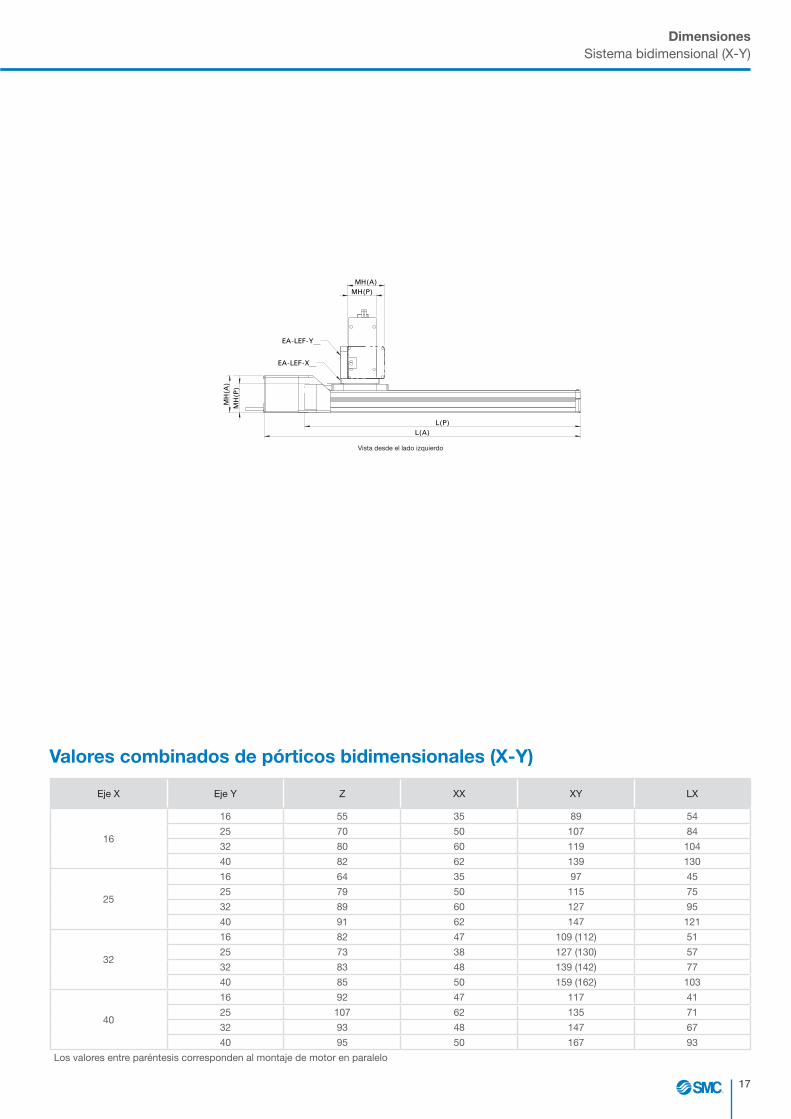
DimensionesSistema bidimensional (X-Y)
Eje X Eje Y Z XX XY LX
16
16 55 35 89 54
25 70 50 107 84
32 80 60 119 104
40 82 62 139 130
25
16 64 35 97 45
25 79 50 115 75
32 89 60 127 95
40 91 62 147 121
32
16 82 47 109 (112) 51
25 73 38 127 (130) 57
32 83 48 139 (142) 77
40 85 50 159 (162) 103
40
16 92 47 117 41
25 107 62 135 71
32 93 48 147 67
40 95 50 167 93
Los valores entre paréntesis corresponden al montaje de motor en paralelo
P
O
N
M
L
K
J
I
H
G
F
E
D
C
B
A
1 2 3 4 5 76 8 9 10 11 12 13 14 15 16 17 18 19 20 2221 23 24
16 17 18 19 20 2221 23 241 2 3 4 5 76 8 9 10 11 12 13 14 15
P
O
N
M
L
K
J
I
H
G
F
E
D
C
B
A
®PROJEKTIONS- METHODE 1
SMC GermanTechnical Center
SIZE:A0
ALL DIMSIN MMEGELSBACH, GERMANY REV. CHANGE NOTE MODIFICATION NAME DATE
MATERIAL/FINISH DRAWN KAISER PRODUCT PART NUMBER
CEV50039-A-070MATERIAL:
DATE 27.04.18
DESIGNED KAISER DESCRIPTION
Gesamtzeichnung_KatalogSURFACE: DATE 30.04.18
CHECKED 14_5 TRACKING NUMBER SCALE
AH
ub
(Z)
Hub(Y)
AA(A)
AA(P)
G
K
MB
(A)M
B(P
)
MH
(P)
MH
(A)
L(P)
L(A)
L(P) L(A)
MH
(P)
MH
(A)
MH(A)
MH(P)
G
XX
Z
L(P)
L(A)
MB
(P)
MB
(A)
XY
Hub(Y)LX
Hu
b(X
)
XX
Z
LX Hub(Y)
Hu
b(X
)
Z
XX
Hub(Y)
Hu
b(Z
)
J
AA(A)
L(A)
G
XX
Z
XY
KM
B(A
)MB
(P)
AA(P)
L(P)
MH
(P)
MH
(A)
PB
(Y)
L(P)
L(A)
MB(A)
MB(P)
Z B(Y)
Z B(Y)
MB(A)
MB(P)
PB
(Y)
J
33:100FINISH:
DATE 16_5
APPROVED 17_5 DOCUMENT NUMBER REVISION SHEET
CEV50039-A-070 0 1 of 1DATE 19_5
© The reproduction, distribution and utilization of this document as well as the communication of its contents to others without express authorization is prohibited. Offenders will be held liable for thepayment of damages. All rights reserved in the event of the grant of a patent, utility model or design. CUSTOMER
REMOVE ALL BURRSAND SHARP EDGES
Rz 12,5
THREADS TO 6g/6HTHD LENGTHS +1.00/-0
2400020001.2200010000.810004000.54001200.3120300.23060.1630.130.5
TOLUP TOOVER
GENERAL TOLERANCESISO 2768-mK (MEDIUM)
LINEAR TOLERANCES
TOLERANCE PRINCIPLESTO ISO 8015
"Unless otherwise noted along with a separate contract or agreement within the Product Specifications, the safty instructions specified in the product catalog are applied. Please contact your local SMC Sales office for further details."
In der Zeichnung werden die Motoren mit Abdeckung dargestelltDie Bezeichnung (A) bzw. (P) steht für axiale oder parallele MotorausführungDie Bezeichnung (X),(Y) bzw. (Z) zeigt die referenzierte Achse
Stützachse (optional)
Arbeitsraum
axiale Motorausführung
parallele Motorausführung
Ansicht von Oben
Arbeitsraum
Stützachse (optional)
Ansicht von Oben
parallele Motorausführung
axiale Motorausführung
In der Zeichnung werden die Motoren mit Abdeckung dargestelltDie Bezeichnung (A) bzw. (P) steht für axiale oder parallele MotorausführungDie Bezeichnung (X),(Y) bzw. (Z) zeigt die referenzierte Achse
Flächenportal (X-Y-Portal)
Ansicht von Oben
axiale Motorausführung
parallele Motorausführung
EA-LEF-X__(entfällt bei Montage auf
Achse Baugröße 16)
EA-LEF-Z__
Ansicht von Links
Linienportal (Y-Z-Portal)
Y-Achse
Z-Achse
Ansicht von Vorne
Arbeitsraum
axiale Motorausführung
parallele Motorausführung
In der Zeichnung werden die Motoren mit Abdeckung dargestelltDie Bezeichnung (A) bzw. (P) steht für axiale oder parallele MotorausführungDie Bezeichnung (X),(Y) bzw. (Z) zeigt die referenzierte Achse
parallele Motorausführung
axiale Motorausführung
X-Achse
Y-Achse
Raumportal (X-Y-Z-Portal)
EA-LEF-Y__
EA-LEF-X__
Ansicht von Links
Ansicht von Vorne
Y-Achse
Arbeitsraum
parallele Motorausführung
axiale Motorausführung
Z-Achse
Ansicht von Vorne
X-Achse
EA-LEF-Z__
EA-LEF-X__
EA-LEF-Z__
EA-LEF-X__(entfällt bei Montage auf
Achse Baugröße 16)
axialeMotorausführung
paralleleMotorausführung
Ansicht von Links
u La uniformidad de la superficie de instalación puede desviarse un máximo de 0.1 mm.
u El esquema muestra los motores con cubiertas.
u Las designaciones (A) y (P) corresponden al diseño de motor axial o paralelo, respectivamente.
u Las designaciones (X), (Y) y (Z) indican los ejes de referencia.
u Puedes obtener los tamaños de conexión de los actuadores individuales e información adicional en el catálogo completo de la serie correspondiente en www.smc.eu.
Valores combinados de pórticos bidimensionales (X-Y)
Vista desde el lado izquierdo

18
DimensionesSistemas tridimensionales (X-Y-Z)
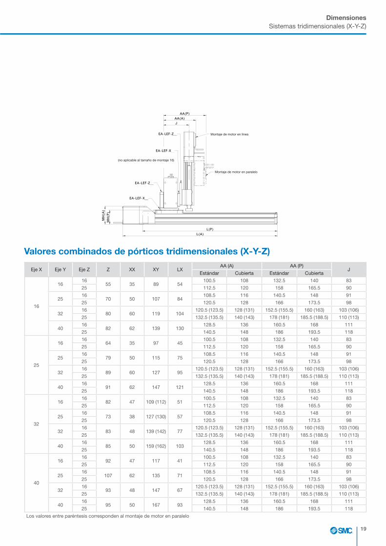
u La uniformidad de la superficie de instalación puede desviarse un máximo de 0.1 mm.
u El esquema muestra los motores con cubiertas.
u Las designaciones (A) y (P) corresponden al diseño de motor axial o paralelo, respectivamente.
u Las designaciones (X), (Y) y (Z) indican los ejes de referencia.
u Puedes obtener los tamaños de conexión de los actuadores individuales e información adicional en el catálogo completo de la serie correspondiente en www.smc.eu.
P
O
N
M
L
K
J
I
H
G
F
E
D
C
B
A
1 2 3 4 5 76 8 9 10 11 12 13 14 15 16 17 18 19 20 2221 23 24
16 17 18 19 20 2221 23 241 2 3 4 5 76 8 9 10 11 12 13 14 15
P
O
N
M
L
K
J
I
H
G
F
E
D
C
B
A
®PROJEKTIONS- METHODE 1
SMC GermanTechnical Center
SIZE:A0
ALL DIMSIN MMEGELSBACH, GERMANY REV. CHANGE NOTE MODIFICATION NAME DATE
MATERIAL/FINISH DRAWN KAISER PRODUCT PART NUMBER
CEV50039-A-070MATERIAL:
DATE 27.04.18
DESIGNED KAISER DESCRIPTION
Gesamtzeichnung_KatalogSURFACE: DATE 30.04.18
CHECKED 14_5 TRACKING NUMBER SCALE
AH
ub
(Z)
Hub(Y)
AA(A)
AA(P)
G
K
MB
(A)M
B(P
)
MH
(P)
MH
(A)
L(P)
L(A)
L(P) L(A)
MH
(P)
MH
(A)
MH(A)
MH(P)
G
XX
Z
L(P)
L(A)
MB
(P)
MB
(A)
XY
Hub(Y)LX
Hu
b(X
)
XX
Z
LX Hub(Y)
Hu
b(X
)
Z
XX
Hub(Y)
Hu
b(Z
)
J
AA(A)
L(A)
G
XX
Z
XY
KM
B(A
)MB
(P)
AA(P)
L(P)
MH
(P)
MH
(A)
PB
(Y)
L(P)
L(A)
MB(A)
MB(P)
Z B(Y)
Z B(Y)
MB(A)
MB(P)
PB
(Y)
J
33:100FINISH:
DATE 16_5
APPROVED 17_5 DOCUMENT NUMBER REVISION SHEET
CEV50039-A-070 0 1 of 1DATE 19_5
© The reproduction, distribution and utilization of this document as well as the communication of its contents to others without express authorization is prohibited. Offenders will be held liable for thepayment of damages. All rights reserved in the event of the grant of a patent, utility model or design. CUSTOMER
REMOVE ALL BURRSAND SHARP EDGES
Rz 12,5
THREADS TO 6g/6HTHD LENGTHS +1.00/-0
2400020001.2200010000.810004000.54001200.3120300.23060.1630.130.5
TOLUP TOOVER
GENERAL TOLERANCESISO 2768-mK (MEDIUM)
LINEAR TOLERANCES
TOLERANCE PRINCIPLESTO ISO 8015
"Unless otherwise noted along with a separate contract or agreement within the Product Specifications, the safty instructions specified in the product catalog are applied. Please contact your local SMC Sales office for further details."
In der Zeichnung werden die Motoren mit Abdeckung dargestelltDie Bezeichnung (A) bzw. (P) steht für axiale oder parallele MotorausführungDie Bezeichnung (X),(Y) bzw. (Z) zeigt die referenzierte Achse
Stützachse (optional)
Arbeitsraum
axiale Motorausführung
parallele Motorausführung
Ansicht von Oben
Arbeitsraum
Stützachse (optional)
Ansicht von Oben
parallele Motorausführung
axiale Motorausführung
In der Zeichnung werden die Motoren mit Abdeckung dargestelltDie Bezeichnung (A) bzw. (P) steht für axiale oder parallele MotorausführungDie Bezeichnung (X),(Y) bzw. (Z) zeigt die referenzierte Achse
Flächenportal (X-Y-Portal)
Ansicht von Oben
axiale Motorausführung
parallele Motorausführung
EA-LEF-X__(entfällt bei Montage auf
Achse Baugröße 16)
EA-LEF-Z__
Ansicht von Links
Linienportal (Y-Z-Portal)
Y-Achse
Z-Achse
Ansicht von Vorne
Arbeitsraum
axiale Motorausführung
parallele Motorausführung
In der Zeichnung werden die Motoren mit Abdeckung dargestelltDie Bezeichnung (A) bzw. (P) steht für axiale oder parallele MotorausführungDie Bezeichnung (X),(Y) bzw. (Z) zeigt die referenzierte Achse
parallele Motorausführung
axiale Motorausführung
X-Achse
Y-Achse
Raumportal (X-Y-Z-Portal)
EA-LEF-Y__
EA-LEF-X__
Ansicht von Links
Ansicht von Vorne
Y-Achse
Arbeitsraum
parallele Motorausführung
axiale Motorausführung
Z-Achse
Ansicht von Vorne
X-Achse
EA-LEF-Z__
EA-LEF-X__
EA-LEF-Z__
EA-LEF-X__(entfällt bei Montage auf
Achse Baugröße 16)
axialeMotorausführung
paralleleMotorausführung
Ansicht von Links
P
O
N
M
L
K
J
I
H
G
F
E
D
C
B
A
1 2 3 4 5 76 8 9 10 11 12 13 14 15 16 17 18 19 20 2221 23 24
16 17 18 19 20 2221 23 241 2 3 4 5 76 8 9 10 11 12 13 14 15
P
O
N
M
L
K
J
I
H
G
F
E
D
C
B
A
®PROJEKTIONS- METHODE 1
SMC GermanTechnical Center
SIZE:A0
ALL DIMSIN MMEGELSBACH, GERMANY REV. CHANGE NOTE MODIFICATION NAME DATE
MATERIAL/FINISH DRAWN KAISER PRODUCT PART NUMBER
CEV50039-A-070MATERIAL:
DATE 27.04.18
DESIGNED KAISER DESCRIPTION
Gesamtzeichnung_KatalogSURFACE: DATE 30.04.18
CHECKED 14_5 TRACKING NUMBER SCALE
AH
ub
(Z)
Hub(Y)
AA(A)
AA(P)
G
K
MB
(A)M
B(P
)
MH
(P)
MH
(A)
L(P)
L(A)
L(P) L(A)
MH
(P)
MH
(A)
MH(A)
MH(P)
G
XX
Z
L(P)
L(A)
MB
(P)
MB
(A)
XY
Hub(Y)LX
Hu
b(X
)
XX
Z
LX Hub(Y)
Hu
b(X
)
Z
XX
Hub(Y)H
ub
(Z)
J
AA(A)
L(A)
G
XX
Z
XY
KM
B(A
)MB
(P)
AA(P)
L(P)
MH
(P)
MH
(A)
PB
(Y)
L(P)
L(A)
MB(A)
MB(P)
Z B(Y)
Z B(Y)
MB(A)
MB(P)
PB
(Y)
J
33:100FINISH:
DATE 16_5
APPROVED 17_5 DOCUMENT NUMBER REVISION SHEET
CEV50039-A-070 0 1 of 1DATE 19_5
© The reproduction, distribution and utilization of this document as well as the communication of its contents to others without express authorization is prohibited. Offenders will be held liable for thepayment of damages. All rights reserved in the event of the grant of a patent, utility model or design. CUSTOMER
REMOVE ALL BURRSAND SHARP EDGES
Rz 12,5
THREADS TO 6g/6HTHD LENGTHS +1.00/-0
2400020001.2200010000.810004000.54001200.3120300.23060.1630.130.5
TOLUP TOOVER
GENERAL TOLERANCESISO 2768-mK (MEDIUM)
LINEAR TOLERANCES
TOLERANCE PRINCIPLESTO ISO 8015
"Unless otherwise noted along with a separate contract or agreement within the Product Specifications, the safty instructions specified in the product catalog are applied. Please contact your local SMC Sales office for further details."
In der Zeichnung werden die Motoren mit Abdeckung dargestelltDie Bezeichnung (A) bzw. (P) steht für axiale oder parallele MotorausführungDie Bezeichnung (X),(Y) bzw. (Z) zeigt die referenzierte Achse
Stützachse (optional)
Arbeitsraum
axiale Motorausführung
parallele Motorausführung
Ansicht von Oben
Arbeitsraum
Stützachse (optional)
Ansicht von Oben
parallele Motorausführung
axiale Motorausführung
In der Zeichnung werden die Motoren mit Abdeckung dargestelltDie Bezeichnung (A) bzw. (P) steht für axiale oder parallele MotorausführungDie Bezeichnung (X),(Y) bzw. (Z) zeigt die referenzierte Achse
Flächenportal (X-Y-Portal)
Ansicht von Oben
axiale Motorausführung
parallele Motorausführung
EA-LEF-X__(entfällt bei Montage auf
Achse Baugröße 16)
EA-LEF-Z__
Ansicht von Links
Linienportal (Y-Z-Portal)
Y-Achse
Z-Achse
Ansicht von Vorne
Arbeitsraum
axiale Motorausführung
parallele Motorausführung
In der Zeichnung werden die Motoren mit Abdeckung dargestelltDie Bezeichnung (A) bzw. (P) steht für axiale oder parallele MotorausführungDie Bezeichnung (X),(Y) bzw. (Z) zeigt die referenzierte Achse
parallele Motorausführung
axiale Motorausführung
X-Achse
Y-Achse
Raumportal (X-Y-Z-Portal)
EA-LEF-Y__
EA-LEF-X__
Ansicht von Links
Ansicht von Vorne
Y-Achse
Arbeitsraum
parallele Motorausführung
axiale Motorausführung
Z-Achse
Ansicht von Vorne
X-Achse
EA-LEF-Z__
EA-LEF-X__
EA-LEF-Z__
EA-LEF-X__(entfällt bei Montage auf
Achse Baugröße 16)
axialeMotorausführung
paralleleMotorausführung
Ansicht von Links
Montaje de motor en línea
Montaje de motor en línea
Montaje de motor en paralelo
Montaje de motor en paralelo
Carrera (Y)
Carrera (Y)
Car
rera
(Z)
Car
rera
(X)
Eje Y
Eje X
Guía de soporte (opcional)
Espacio de trabajo
Eje Z
Espacio de trabajo
19
DimensionesSistemas tridimensionales (X-Y-Z)
Eje X Eje Y Eje Z Z XX XY LXAA (A) AA (P)
JEstándar Cubierta Estándar Cubierta
16
1616
55 35 89 54100.5 108 132.5 140 83
25 112.5 120 158 165.5 90
2516
70 50 107 84108.5 116 140.5 148 91
25 120.5 128 166 173.5 98
3216
80 60 119 104120.5 (123.5) 128 (131) 152.5 (155.5) 160 (163) 103 (106)
25 132.5 (135.5) 140 (143) 178 (181) 185.5 (188.5) 110 (113)
4016
82 62 139 130128.5 136 160.5 168 111
25 140.5 148 186 193.5 118
25
1616
64 35 97 45100.5 108 132.5 140 83
25 112.5 120 158 165.5 90
2516
79 50 115 75108.5 116 140.5 148 91
25 120.5 128 166 173.5 98
3216
89 60 127 95120.5 (123.5) 128 (131) 152.5 (155.5) 160 (163) 103 (106)
25 132.5 (135.5) 140 (143) 178 (181) 185.5 (188.5) 110 (113)
4016
91 62 147 121128.5 136 160.5 168 111
25 140.5 148 186 193.5 118
32
1616
82 47 109 (112) 51100.5 108 132.5 140 83
25 112.5 120 158 165.5 90
2516
73 38 127 (130) 57108.5 116 140.5 148 91
25 120.5 128 166 173.5 98
3216
83 48 139 (142) 77120.5 (123.5) 128 (131) 152.5 (155.5) 160 (163) 103 (106)
25 132.5 (135.5) 140 (143) 178 (181) 185.5 (188.5) 110 (113)
4016
85 50 159 (162) 103128.5 136 160.5 168 111
25 140.5 148 186 193.5 118
40
1616
92 47 117 41100.5 108 132.5 140 83
25 112.5 120 158 165.5 90
2516
107 62 135 71108.5 116 140.5 148 91
25 120.5 128 166 173.5 98
3216
93 48 147 67120.5 (123.5) 128 (131) 152.5 (155.5) 160 (163) 103 (106)
25 132.5 (135.5) 140 (143) 178 (181) 185.5 (188.5) 110 (113)
4016
95 50 167 93128.5 136 160.5 168 111
25 140.5 148 186 193.5 118
Los valores entre paréntesis corresponden al montaje de motor en paralelo
P
O
N
M
L
K
J
I
H
G
F
E
D
C
B
A
1 2 3 4 5 76 8 9 10 11 12 13 14 15 16 17 18 19 20 2221 23 24
16 17 18 19 20 2221 23 241 2 3 4 5 76 8 9 10 11 12 13 14 15
P
O
N
M
L
K
J
I
H
G
F
E
D
C
B
A
®PROJEKTIONS- METHODE 1
SMC GermanTechnical Center
SIZE:A0
ALL DIMSIN MMEGELSBACH, GERMANY REV. CHANGE NOTE MODIFICATION NAME DATE
MATERIAL/FINISH DRAWN KAISER PRODUCT PART NUMBER
CEV50039-A-070MATERIAL:
DATE 27.04.18
DESIGNED KAISER DESCRIPTION
Gesamtzeichnung_KatalogSURFACE: DATE 30.04.18
CHECKED 14_5 TRACKING NUMBER SCALE
AH
ub
(Z)
Hub(Y)
AA(A)
AA(P)
G
K
MB
(A)M
B(P
)
MH
(P)
MH
(A)
L(P)
L(A)
L(P) L(A)
MH
(P)
MH
(A)
MH(A)
MH(P)
G
XX
Z
L(P)
L(A)
MB
(P)
MB
(A)
XY
Hub(Y)LX
Hu
b(X
)
XX
Z
LX Hub(Y)
Hu
b(X
)
Z
XX
Hub(Y)
Hu
b(Z
)
J
AA(A)
L(A)
G
XX
Z
XY
KM
B(A
)MB
(P)
AA(P)
L(P)
MH
(P)
MH
(A)
PB
(Y)
L(P)
L(A)
MB(A)
MB(P)
Z B(Y)
Z B(Y)
MB(A)
MB(P)
PB
(Y)
J
33:100FINISH:
DATE 16_5
APPROVED 17_5 DOCUMENT NUMBER REVISION SHEET
CEV50039-A-070 0 1 of 1DATE 19_5
© The reproduction, distribution and utilization of this document as well as the communication of its contents to others without express authorization is prohibited. Offenders will be held liable for thepayment of damages. All rights reserved in the event of the grant of a patent, utility model or design. CUSTOMER
REMOVE ALL BURRSAND SHARP EDGES
Rz 12,5
THREADS TO 6g/6HTHD LENGTHS +1.00/-0
2400020001.2200010000.810004000.54001200.3120300.23060.1630.130.5
TOLUP TOOVER
GENERAL TOLERANCESISO 2768-mK (MEDIUM)
LINEAR TOLERANCES
TOLERANCE PRINCIPLESTO ISO 8015
"Unless otherwise noted along with a separate contract or agreement within the Product Specifications, the safty instructions specified in the product catalog are applied. Please contact your local SMC Sales office for further details."
In der Zeichnung werden die Motoren mit Abdeckung dargestelltDie Bezeichnung (A) bzw. (P) steht für axiale oder parallele MotorausführungDie Bezeichnung (X),(Y) bzw. (Z) zeigt die referenzierte Achse
Stützachse (optional)
Arbeitsraum
axiale Motorausführung
parallele Motorausführung
Ansicht von Oben
Arbeitsraum
Stützachse (optional)
Ansicht von Oben
parallele Motorausführung
axiale Motorausführung
In der Zeichnung werden die Motoren mit Abdeckung dargestelltDie Bezeichnung (A) bzw. (P) steht für axiale oder parallele MotorausführungDie Bezeichnung (X),(Y) bzw. (Z) zeigt die referenzierte Achse
Flächenportal (X-Y-Portal)
Ansicht von Oben
axiale Motorausführung
parallele Motorausführung
EA-LEF-X__(entfällt bei Montage auf
Achse Baugröße 16)
EA-LEF-Z__
Ansicht von Links
Linienportal (Y-Z-Portal)
Y-Achse
Z-Achse
Ansicht von Vorne
Arbeitsraum
axiale Motorausführung
parallele Motorausführung
In der Zeichnung werden die Motoren mit Abdeckung dargestelltDie Bezeichnung (A) bzw. (P) steht für axiale oder parallele MotorausführungDie Bezeichnung (X),(Y) bzw. (Z) zeigt die referenzierte Achse
parallele Motorausführung
axiale Motorausführung
X-Achse
Y-Achse
Raumportal (X-Y-Z-Portal)
EA-LEF-Y__
EA-LEF-X__
Ansicht von Links
Ansicht von Vorne
Y-Achse
Arbeitsraum
parallele Motorausführung
axiale Motorausführung
Z-Achse
Ansicht von Vorne
X-Achse
EA-LEF-Z__
EA-LEF-X__
EA-LEF-Z__
EA-LEF-X__(entfällt bei Montage auf
Achse Baugröße 16)
axialeMotorausführung
paralleleMotorausführung
Ansicht von Links
Valores combinados de pórticos tridimensionales (X-Y-Z)
(no aplicable al tamaño de montaje 16)
Montaje de motor en paralelo
Montaje de motor en línea

20
AccesoriosLongitud del cable desde el eje X en m:
1.5 3.0 5.0 8.0 10 15 20
Freno:
Ninguno Eje vertical Eje horizontal y vertical
Elementos adicionales1)
Pinza (G):
Pinza eléctrica Pinza neumática
Actuador de giro (R):
Actuador de giro eléctrico Actuador de giro neumático
Otro:
1) Kits de montaje para elementos adicionales bajo pedido
Tipo de control
PROFINET
Tren de pulsos
EtherCAT
I/O digitales
EtherNet/IP
Controlador de 4 ejes
IO-Link
Controlador de 3 ejes
Diseña tu aplicación
Toma de datos
Sistemas de ejes Pórtico en línea Y-Z Pórtico bidimensional X-Y Pórtico tridimensional X-Y-Z X-Y-Z con guía pasiva
X-Y con guía pasiva
Contacta con el departamento técnico de SMC ([email protected]) en caso de requerir asistencia en la selección de los ejes que requiere tu aplicación.

21
Diseña tu aplicaciónToma de datos
Tiempo mínimo para distancias recorridas:
Tiempo de recorrido X: ms
Tiempo de recorrido Y: ms
Tiempo de recorrido Z: ms
Tiempo de recorrido G: ms
Giro R: ms
Información sobre la carga/dinámicaLongitudes de carrera:
Carrera en eje X: mm
Carrera en eje XY: mm
Carrera en eje Z: mm
Carrera de pinza: mm
Ángulo de giro: grados
Peso: kg
Disposición de la carga Sin eje Z:Lx: mm
Ly: mm
Lz: mm
Con eje Z:
L: mm
Comentarios/esquema
Para un dimensionamiento correcto se recomienda utilizar el procedimiento de selección del catálogo de la serie o utilizar el software de selección disponible en www.smc.eu

22

23
Notas

www.smc.eu
MA18VK-556bES