sinamics g120 cu240e-2, cu240e-2 f, cu240e-2 dp, cu240e-2 dp … · sinamics g120 cu240e-2,...
TRANSCRIPT

Service & Support
Answers for industry.
How do I configure extended PROFIsafe on the CU240E-2?
SINAMICS G120 CU240E-2, CU240E-2 F, CU240E-2 DP, CU240E-2 DP-F, CU240E-2 PN, CU240E-2 PN-F,
FAQ March 2013

Question
2 How do I configure extended PROFIsafe on the CU240E?
1.0, Item-ID: 68188133
This entry is from the Siemens Industry Online Support. The general terms of use (http://www.siemens.com/terms_of_use) apply. Clicking the link below directly displays the download page of this document. http://support.automation.siemens.com/WW/view/en/68188133 Caution The functions and solutions described in this article confine themselves to the realization of the automation task predominantly. Please take into account furthermore that corresponding protective measures have to be taken up in the context of Industrial Security when connecting your equipment to other parts of the plant, the enterprise network or the Internet. Further information can be found under the Content-ID 50203404. http://support.automation.siemens.com/WW/view/en/50203404
Question How do I configure extended PROFIsafe on the CU240E?
Answer The instructions and notes listed in this document provide a detailed answer to this question.
Table of content
How do I configure extended PROFIsafe on the CU240E? 1.0, Item-ID: 68188133 3
Table of content 1 Configuring Extended PROFIsafe..................................................................4
1.1 Prerequisites .....................................................................................4 1.2 Configuring the devices .....................................................................5 1.3 Configuring the drive for safety in STARTER software .....................10

1 Configuring Extended PROFIsafe
4 How do I configure extended PROFIsafe on the CU240E?
1.0, Item-ID: 68188133
1 Configuring Extended PROFIsafe 1.1 Prerequisites
In the following explanation of configuring extended PROFIsafe functions the devices used during the configuration are a CU240E-2 PN Control Module with an S7-315F PN/DP V3.2 Prior to starting the setup process for safety, the Name and IP address of the control unit should be set. This name and IP must match the Name and IP that is set in the hardware configuration of the S7 project. Two options exist; telegram 30 and telegram 900. Both telegrams provide support for extended safety, but telegram 900 offers one higher level option. Telegram 900 provides feedback to the master control on the status of the F-DI
digital inputs. Even if the F-DI inputs are not being used in the drive safety configuration, the status of the inputs will be returned to the master control, allowing them to be used in the higher level logic.
Telegram 900 will only work with a CU240E-2 XX-F (DP or PN) safety control unit. If you are going to evaluate the status of the Drive unit fail-safe inputs at the master control level, and if you are using a –F safety CU, Profi-safe telegram 900 will be the correct choice.
For all other applications, telegram 30 should be used.
NOTE When using telegram 900, the safety inputs in the drive must be set to “enable” to prevent a configuration fault (F1653). This will be explained in a later step. Likewise, if using telegram 30, the safety inputs must be set to “Inhibit” in the drive or a configuration fault will be generated. Again, telegram 900 can only be used in the –F safety control units..

1 Configuring Extended PROFIsafe
How do I configure extended PROFIsafe on the CU240E? 1.0, Item-ID: 68188133 5
1.2 Configuring the devices
To configure the PROFIsafe functions the following procedure should be performed: 1. Configure the Hardware configuration with the appropriate CPU and drive.
For this example, we will use telegram 20 for control of the drive and PROFI-safe telegram 900 for safety. Add the telegrams for the device.
2. Double click on the safety telegram and select the “profisafe” tab. 3. Record the HEX value for F_DEST_ADD to be used later (in this case it is C8). Figure 1-1
4. Double click on the CPU to open the properties. 5. Select the cyclic interrupts tab. 6. Set OB35 = 75. 7. Select the Protection tab and select level 3. 8. Set the password (make sure you record it for future use) and select the box
“CPU contains safety program”. 9. Click OK. 10. Record the input and output addresses for the profisafe telegram and standard
telegram for use later. 11. Record the address of the input module being used for the safety inputs. 12. Save and compile the hardware config – download it to the CPU and close the
HW Config window. 13. In the Simatic Manager add the F_CALL and F_LAD blocks.
1 Configuring Extended PROFIsafe
6 How do I configure extended PROFIsafe on the CU240E?
1.0, Item-ID: 68188133
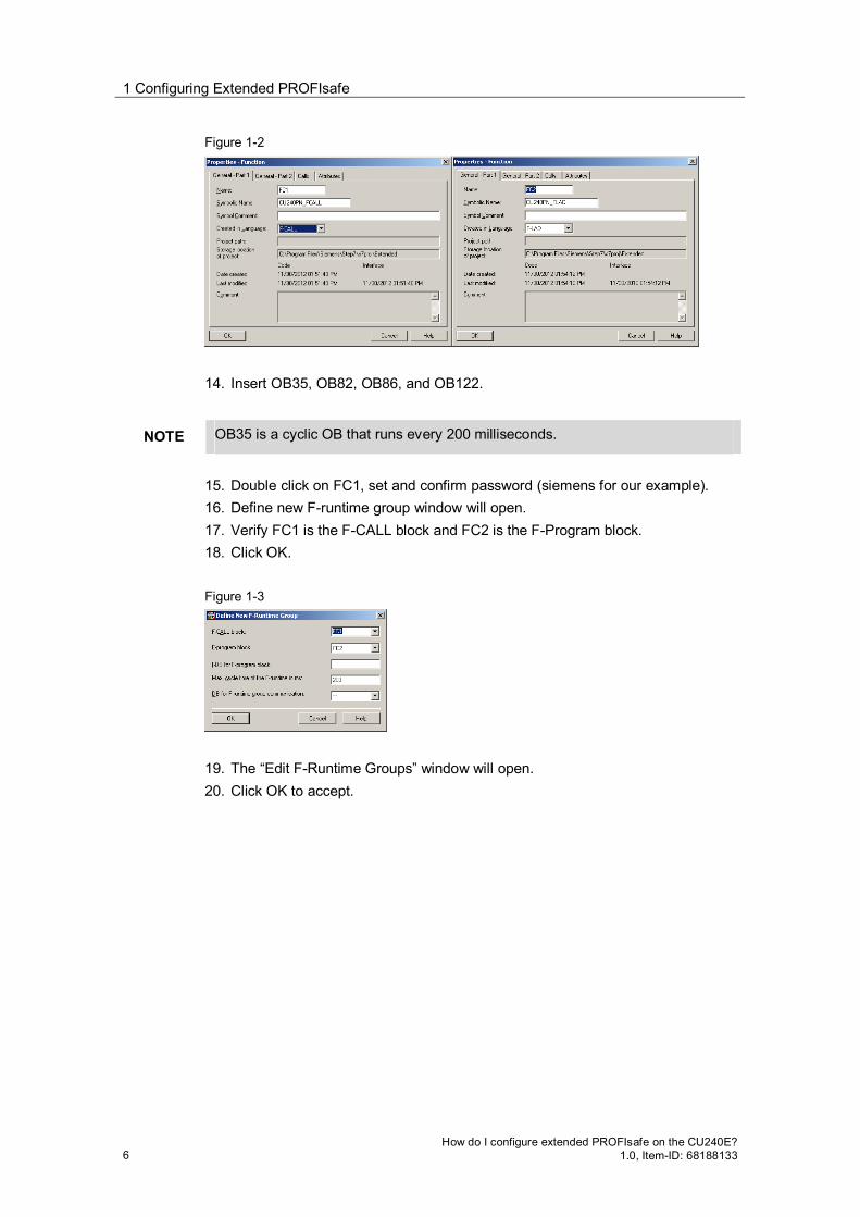
Figure 1-2
14. Insert OB35, OB82, OB86, and OB122.
NOTE OB35 is a cyclic OB that runs every 200 milliseconds.
15. Double click on FC1, set and confirm password (siemens for our example). 16. Define new F-runtime group window will open. 17. Verify FC1 is the F-CALL block and FC2 is the F-Program block. 18. Click OK. Figure 1-3
19. The “Edit F-Runtime Groups” window will open. 20. Click OK to accept.

1 Configuring Extended PROFIsafe
How do I configure extended PROFIsafe on the CU240E? 1.0, Item-ID: 68188133 7
Figure 1-4
21. The safety program window will open. 22. Compile the safety parameter and verify they compile with no errors. 23. Select download and download the safety program to the CPU. 24. After downloading, close the safety program window. Figure 1-5
25. Open FC 2 and add 4 rungs to connect inputs to bits in the safety telegram. In our example, the safety telegram 900 started at 1.0, so we will connect switches to set bits 1.0, 1.1, 1.4, and DB546.DBX0.2, which is the “acknowledge for reintegration” bit. DB546 was automatically generated when we added the safety function to the CPU. This DB address may be different depending on your CPU type.
NOTE our input addresses are in red because I am not using a safety input module (F-DI).

1 Configuring Extended PROFIsafe
8 How do I configure extended PROFIsafe on the CU240E?
1.0, Item-ID: 68188133
Figure 1-6
26. Save and close the editor window. 27. Double click on OB35 to open it in the editor. 28. Add FC1 to the first network. Save and close. Figure 1-7
29. Select “Options” - “edit safety program”

1 Configuring Extended PROFIsafe
How do I configure extended PROFIsafe on the CU240E? 1.0, Item-ID: 68188133 9
Figure 1-8
30. If prompted enter the password. 31. Compile the safety program and verify it compiles with no errors. Figure 1-9
32. Select Download to load the safety program into the CPU. 33. Close the safety program window. This now has our PLC configured for extended safety for the G120 drive. Now we need to configure the drive for safety with Starter software.

1 Configuring Extended PROFIsafe
10 How do I configure extended PROFIsafe on the CU240E?
1.0, Item-ID: 68188133
1.3 Configuring the drive for safety in STARTER software
1. In the Simatic Manager highlight the project name. 2. Select “insert” – “Sinamics”.
A window will open to allow you to select your drive. We are using a CU240E-2 PN-F Firmware 4.5.
3. Set the IP address and click OK to insert the selected drive into the project. Figure 1-10
4. Now select the drive and click on “commissioning”. Starter should launch. Figure 1-11
5. In starter, click the icon “connect to selected target devices”. If the IP was set correctly, starter should connect to the drive, and the following window will appear.

1 Configuring Extended PROFIsafe
How do I configure extended PROFIsafe on the CU240E? 1.0, Item-ID: 68188133 11
Figure 1-12
6. Select “load hardware configuration to PG” and the Power module type will be
uploaded to the project. Next, the online/offline comparison window will open. If your starter project has default values. 7. Select “load to PG” to upload the current parameters from the drive to the
project. 8. Acknowledge the upload then close the comparison window. Figure 1-13
We are now online with our drive, and can confirm this by the green “coupling” at the left of the drive name.
1 Configuring Extended PROFIsafe
12 How do I configure extended PROFIsafe on the CU240E?
1.0, Item-ID: 68188133
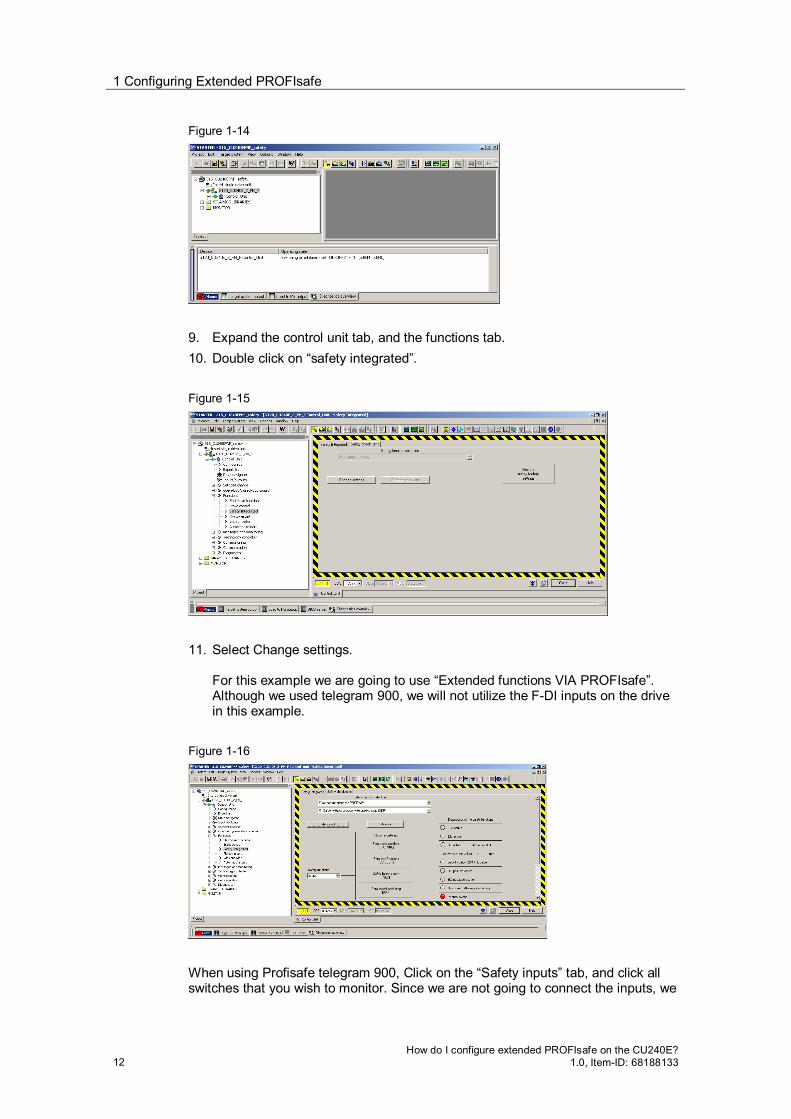
Figure 1-14
9. Expand the control unit tab, and the functions tab. 10. Double click on “safety integrated”. Figure 1-15
11. Select Change settings.
For this example we are going to use “Extended functions VIA PROFIsafe”. Although we used telegram 900, we will not utilize the F-DI inputs on the drive in this example.
Figure 1-16
When using Profisafe telegram 900, Click on the “Safety inputs” tab, and click all switches that you wish to monitor. Since we are not going to connect the inputs, we

1 Configuring Extended PROFIsafe
How do I configure extended PROFIsafe on the CU240E? 1.0, Item-ID: 68188133 13
will leave all 3 switches “OPEN”, but we will set the selection dropdown to “enable” and click close.
WARNING
Failure to match this step with the selected telegram will result in a F01653 and/or a F01711 fault (profisafe configuration error).
When using telegram 30, make sure the safety inputs are set to inhibit.
When using telegram 900, make sure they are enabled to prevent a configuration error on the drive.
Figure 1-18
12. Click on “Configuration” and enter the PROFIsafe address.
This address is the value we recorded from F_DEST_ADD in the safety telegram earlier.
Figure 1-19
13. Click STO tab and set the forced checking procedure time (default t=8 hours
max is 9000 hours)

1 Configuring Extended PROFIsafe
14 How do I configure extended PROFIsafe on the CU240E?
1.0, Item-ID: 68188133
Figure 1-20
14. Click on the Safe Limited Speed (SLS) tab and enter the desired velocity
allowed when SLS is active. Figure 1-21
15. Set the safety functions to enable. Figure 1-22
16. Click on “copy parameters” then activate settings”.
You will be prompted to change the safety password. The default is 0, and you can either leave it at 0 or change it.
NOTE If it is changed, the password must be documented for future reference. If the password is lost, it can not be recovered and safety cannot be modified or disabled.

1 Configuring Extended PROFIsafe
How do I configure extended PROFIsafe on the CU240E? 1.0, Item-ID: 68188133 15
17. You will be prompted to save to rom. Click okay, and after this completes, go
offline and cycle power on drive to enable the modified safety settings. After a power cycle, if the safety light is blinking, an acceptance may be required. Cycle each of the inputs for each safety input to perform the safety acceptance. When all inputs are active, the Yellow safety indicator should be on steady. When any of the inputs are turned off, the yellow safety indicator should be blinking, indicating a safety condition. When the safety light is blinking, the drive will be inhibited from normal operation. If SLS (safe limited speed) is active, the drive will only run at the speed programmed in the SLS tab above. Figure 1-23
Any other safety input will inhibit the drive from running. If the red BF light is blinking, then you do not have communications between your PLC and the drive. Verify the name and IP of the control unit match the name and IP programmed into the hardware configuration and that the project has been downloaded correctly. If you verify the IP and hardware configuration is correct and a bus fault is generated when you enable safety, default the drive back to factory settings and reconfigure. Occasionally the drive configuration will get corrupted preventing the safety telegram from communicating correctly with the drive. Reset both the safety setup and the drive back to factory defaults, the reconfigure.