migration of cu240e/s to cu240b/e-2 and cu250s-2 ... of content 4 migration of cu240e/s to...
TRANSCRIPT

Service & Support
Answers for industry.
Migration of CU240E/S to CU240B/E-2 and CU250S-2 (firmware V4.5)
SINAMICS G120
FAQ March 2013

Question
2 Migration of CU240E/S to CU240B/E-2 and CU250S-2 (firmware V4.5)
Version 1.0, Item-ID: 70021820
This entry is from the Siemens Industry Online Support. The general terms of use (http://www.siemens.com/terms_of_use) apply. Clicking the link below directly displays the download page of this document. http://support.automation.siemens.com/WW/view/en/70021820 Caution The functions and solutions described in this article confine themselves to the realization of the automation task predominantly. Please take into account furthermore that corresponding protective measures have to be taken up in the context of Industrial Security when connecting your equipment to other parts of the plant, the enterprise network or the Internet. Further information can be found under the Content-ID 50203404. http://support.automation.siemens.com/WW/view/en/50203404
Question What do I have to observe if I wish to replace a Control Unit CU240E or a member of the CU240S family (CU240S, CU240S DP, CU240S DP-F, CU240S PN or CU240S PN-F) of the SINAMICS G120 by a Control Unit from the 2nd generation (Firmware V4.5)?
Answer The instructions and notes listed in this document provide a detailed answer to this question.

Table of content
Migration of CU240E/S to CU240B/E-2 and CU250S-2 (firmware V4.5) Version 1.0, Item-ID: 70021820 3
Table of content 1 Migrating the CU240E/S Control Unit to the CU240B/E-2 and
CU250S-2 Control Units ................................................................................. 5 2 Hardware ......................................................................................................... 6
2.1 Comparison of the dimensions ........................................................... 6 2.2 Number of inputs and outputs ............................................................ 6 2.2.1 CU240B-2 Control Unit ...................................................................... 6 2.2.2 CU240E-2 Control Unit ...................................................................... 6 2.2.3 CU240E-2 F Control Unit ................................................................... 7 2.2.4 CU250S-2 Control Unit ...................................................................... 7 2.3 Overview of the terminals .................................................................. 8
3 Encoder connection ..................................................................................... 11
3.1 Connection at the terminal strip........................................................ 11 3.2 Connection at Sub-D connectors ..................................................... 11 3.3 Connection with Drive-CLiQ ............................................................. 12 3.4 Combination of encoders for speed and position control................... 13
4 BOP-2 and IOP operator panels ................................................................... 14
4.1 Manual operation with BOP-2 / IOP ................................................. 14 4.2 Status signals of the BOP-2 / IOP operating elements ...................... 15
5 Parameterization .......................................................................................... 16
5.1 Quick commissioning ....................................................................... 16 5.2 User-defined parameters ................................................................. 16 5.3 Macro drive unit ............................................................................... 17 5.3.1 CU240B-2 Control Unit .................................................................... 17 5.3.2 CU240E-2 Control Unit .................................................................... 18 5.3.3 CU250S-2 Control Unit .................................................................... 21 5.4 Expanded command/drive data sets ................................................ 23 5.5 Selecting the motor type .................................................................. 23 5.5.1 CU240B-2 and CU240E-2 Control Units .......................................... 23 5.5.2 CU250S-2 Control Unit .................................................................... 24 5.6 Selecting the encoder type............................................................... 24 5.7 Selecting technological units ............................................................ 25 5.8 Operating hours counter .................................................................. 26 5.9 Digital inputs .................................................................................... 26 5.9.1 CU240B/E-2 Control Unit ................................................................. 26 5.9.2 CU250S-2 Control Unit .................................................................... 27 5.9.3 Forward/backward parameterization ................................................ 29 5.9.4 Change relating to fail-safe inputs (F-DI) .......................................... 29 5.9.5 Transferring the status of F-DI via PROFIsafe .................................. 29 5.9.6 Simulation Mode .............................................................................. 30 5.9.7 Monitoring the load/speed via digital input ........................................ 30 5.10 Digital outputs .................................................................................. 32 5.10.1 Changed parameter numbers .......................................................... 32 5.10.2 Hardware change ............................................................................ 32 5.11 Analog inputs ................................................................................... 33 5.11.1 Simulation mode .............................................................................. 33 5.11.2 Dead band ....................................................................................... 34 5.12 Scaling of the setpoint channel ........................................................ 34 5.13 Motorized potentiometer .................................................................. 34 5.14 Second ramp function via the JOG ramp-function generator
changed .......................................................................................... 35 5.15 Flying restart.................................................................................... 35
Table of content
4 Migration of CU240E/S to CU240B/E-2 and CU250S-2 (firmware V4.5)
Version 1.0, Item-ID: 70021820
5.16 Automatic restart ............................................................................. 35 5.17 Expanded motor holding brake function ........................................... 36 5.18 Setting dynamic braking................................................................... 36 5.19 Control modes ................................................................................. 36 5.20 Voltage boost .................................................................................. 37 5.21 Speed-dependent controller adaptation ............................................ 37 5.22 Motor data identification ................................................................... 38 5.23 Change for reference quantities ....................................................... 38 5.24 Free function blocks......................................................................... 38 5.25 Technology controller ...................................................................... 39 5.26 Fixed setpoints that can be freely used ............................................ 39 5.27 Change, deactivating the BF-LED .................................................... 40 5.28 Wobbulation generator has been eliminated .................................... 40 5.29 Positioning down ramp has been eliminated .................................... 40 5.30 Memory card ................................................................................... 40 5.30.1 Transferring projects using a memory card ...................................... 40 5.30.2 Handling memory cards ................................................................... 40
6 Performance vector control ......................................................................... 41
6.1 Vector control without encoder SLVC (sensorless) ........................... 41 6.2 Vector control with encoder.............................................................. 42 6.3 Increased ruggedness of the vector control ...................................... 42
7 Communication ............................................................................................ 43
7.1 GSD files ......................................................................................... 43 7.2 Routing through a CPU .................................................................... 43 7.3 Teleservice ...................................................................................... 44 7.3.1 Teleservice via a CPU ..................................................................... 44 7.3.2 Teleservice directly via the fieldbus .................................................. 45 7.4 Slave-to-slave communication (direct data exchange) ...................... 45 7.5 Direct HMI connection ..................................................................... 45
8 Safety functions ........................................................................................... 46
8.1 New and extended safety functions .................................................. 47 8.1.1 Extended SS1 (Safe Stop 1) ............................................................ 47 8.1.2 Extension of SLS (Safely Limited Speed) ......................................... 49 8.1.3 New safety function SDI (Safe Direction) ......................................... 49 8.1.4 New safety function SSM (Safe Speed Monitor) ............................... 50 8.2 Standard STARTER parameterizing screen forms ........................... 50 8.3 Simplified parameterization .............................................................. 50 8.4 Offline safety parameter assignment ................................................ 51 8.5 Acceptance report ........................................................................... 51 8.6 Changing the reference quantity ...................................................... 51 8.7 Group drives .................................................................................... 51 8.8 Changes to the PROFIsafe telegram ............................................... 52 8.8.1 Previous CU240E/S PROFIsafe telegram 30 ................................... 52 8.8.2 New CU240B/E-2, CU250S-2 PROFIsafe telegram 30 ..................... 52 8.8.3 New CU240B/E-2, CU250S-2 PROFIsafe telegram 900 ................... 53 8.9 Transferring the status of F-DI via PROFIsafe .................................. 53
9 Drive fault messages .................................................................................... 54
1 Migrating the CU240E/S Control Unit to the CU240B/E-2 and CU250S-2 Control Units
Migration of CU240E/S to CU240B/E-2 and CU250S-2 (firmware V4.5) Version 1.0, Item-ID: 70021820 5
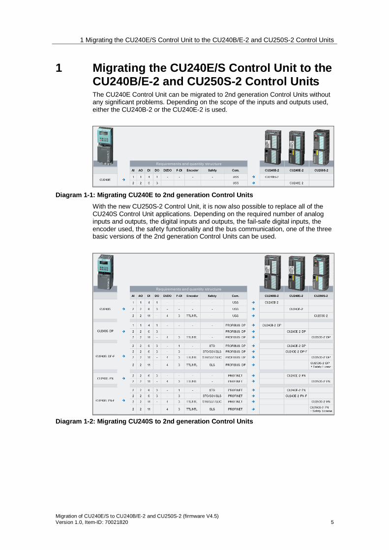
1 Migrating the CU240E/S Control Unit to the CU240B/E-2 and CU250S-2 Control Units The CU240E Control Unit can be migrated to 2nd generation Control Units without any significant problems. Depending on the scope of the inputs and outputs used, either the CU240B-2 or the CU240E-2 is used.
Diagram 1-1: Migrating CU240E to 2nd generation Control Units
With the new CU250S-2 Control Unit, it is now also possible to replace all of the CU240S Control Unit applications. Depending on the required number of analog inputs and outputs, the digital inputs and outputs, the fail-safe digital inputs, the encoder used, the safety functionality and the bus communication, one of the three basic versions of the 2nd generation Control Units can be used.
Diagram 1-2: Migrating CU240S to 2nd generation Control Units

2 Hardware
6 Migration of CU240E/S to CU240B/E-2 and CU250S-2 (firmware V4.5)
Version 1.0, Item ID: 70021820
2 Hardware 2.1 Comparison of the dimensions
CU240E CU240S CU240B-2 CU240E-2 CU250S-2
Height 195mm 177mm 199mm 199mm 199mm
Width 73mm 73mm 73mm 73mm 73mm
Depth with BOP
31mm 63mm 53mm 53mm 68mm
Depth with IOP
- - 63mm 63mm 78mm
Diagram 2-1: Dimensions of the Control Units
2.2 Number of inputs and outputs
2.2.1 CU240B-2 Control Unit
The CU240B-2 Control Unit has the following inputs and outputs: digital inputs, isolated, PNP/NPN switching 1 digital output (relay, 30V DC/0.5A) 1 analog input 0 – 10V, 0/4 – 20mA 1 analog output 0 – 10V, 0/4 – 20mA 1 motor temperature sensor input for PTC, KTY, Thermo-Click +24V connection, external, output +24V/200mA, output +10V/10mA
Die CU240B-2 Control Unit is available with two different communication types: RS485 with USS protocol, Modbus/RTU PROFIBUS DP
2.2.2 CU240E-2 Control Unit
The CU240B-2 Control Unit has the following inputs and outputs: 6 digital inputs, isolated, PNP/NPN switching Optionally 2 digital inputs as F-DI

2 Hardware
Migration of CU240E/S to CU240B/E-2 and CU250S-2 (firmware V4.5) Version 1.0, Item-ID: 70021820 7
digital outputs (two relays, 30V DC/0.5A, 1 transistor 30V DC/0.5A) 2 analog inputs 0 – 10V, 0/4 – 20mA 2 analog outputs 0 – 10V, 0/4 – 20mA 1 motor temperature sensor input for PTC, KTY, Thermo-Click +24V connection, external, output +24V/200mA, output +10V/10mA
Die CU240E-2 Control Unit is available with three different communication types: RS485 with USS protocol, Modbus/RTU PROFIBUS DP PROFINET
2.2.3 CU240E-2 F Control Unit
The CU240E-2 F Control Unit has the following inputs and outputs: 6 digital inputs, isolated, PNP/NPN switching Optionally 6 digital inputs as F-DI digital outputs (two relays, 30V DC/0.5A, 1 transistor 30V DC/0.5A) 2 analog inputs 0 – 10V, 0/4 – 20mA 2 analog outputs 0 – 10V, 0/4 – 20mA 1 motor temperature sensor input for PTC, KTY, Thermo-Click +24V connection, external, output +24V/200mA, output +10V/10mA
The CU240E-2 F Control Unit is available with three different communication types: RS485 with USS protocol, Modbus/RTU PROFIBUS DP PROFINET
2.2.4 CU250S-2 Control Unit
The CU250S-2 Control Unit has the following inputs and outputs: 11 digital inputs, isolated, PNP/NPN switching Optionally 6 digital inputs as F-DI 2 digital outputs as F-DO, relay NO/NC, 30V DC 0.5A 1 digital output as open collector 30V DC 0.5A 2 analog inputs 0 – 10V, 0/4 – 20mA 2 analog outputs 0 – 10V, 0/4 – 20mA 1 motor temperature sensor input for PTC, KTY, Thermo-Click +24V connection, external, output +24V/200mA, output +10V/10mA
Die CU250S-2 F Control Unit is available with four different communication types: RS485 with USS protocol, Modbus/RTU PROFIBUS DP PROFINET CANopen
2 Hardware
8 Migration of CU240E/S to CU240B/E-2 and CU250S-2 (firmware V4.5)
Version 1.0, Item ID: 70021820
2.3 Overview of the terminals
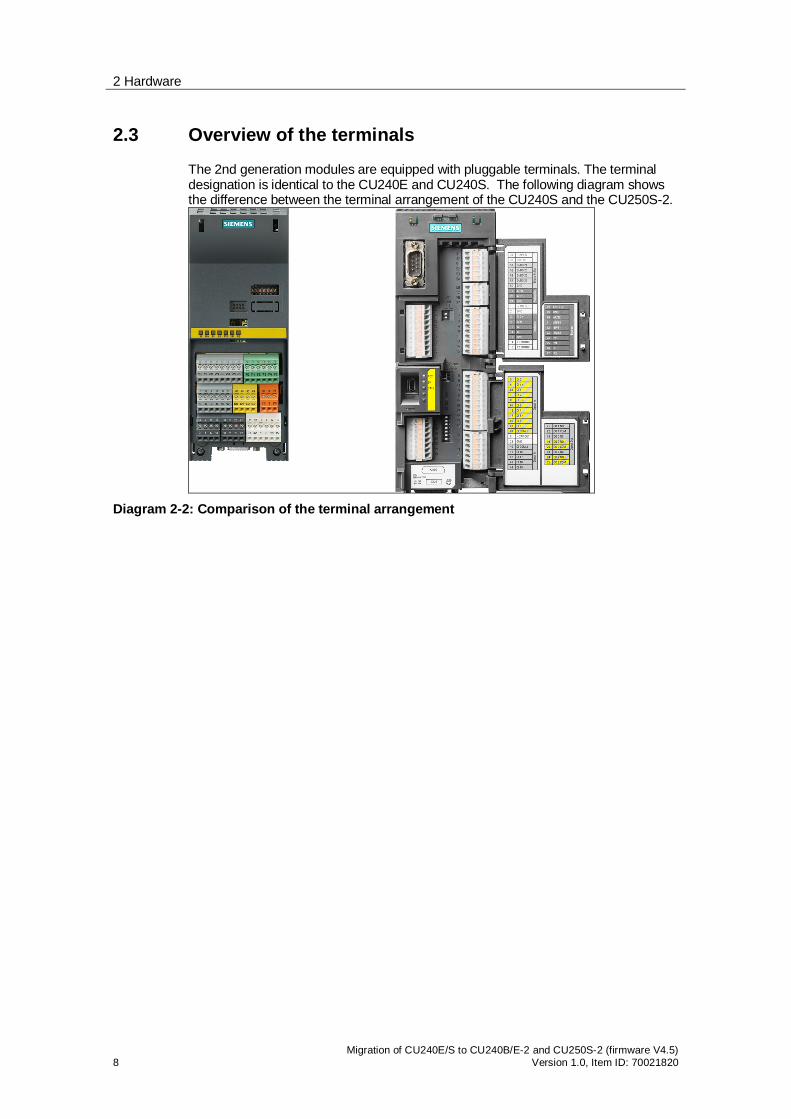
The 2nd generation modules are equipped with pluggable terminals. The terminal designation is identical to the CU240E and CU240S. The following diagram shows the difference between the terminal arrangement of the CU240S and the CU250S-2.
Diagram 2-2: Comparison of the terminal arrangement

2 Hardware
Migration of CU240E/S to CU240B/E-2 and CU250S-2 (firmware V4.5) Version 1.0, Item-ID: 70021820 9
Diagram 2-1: Comparison terminals CU240E against CU240B/E-2
2 Hardware
10 Migration of CU240E/S to CU240B/E-2 and CU250S-2 (firmware V4.5)
Version 1.0, Item ID: 70021820
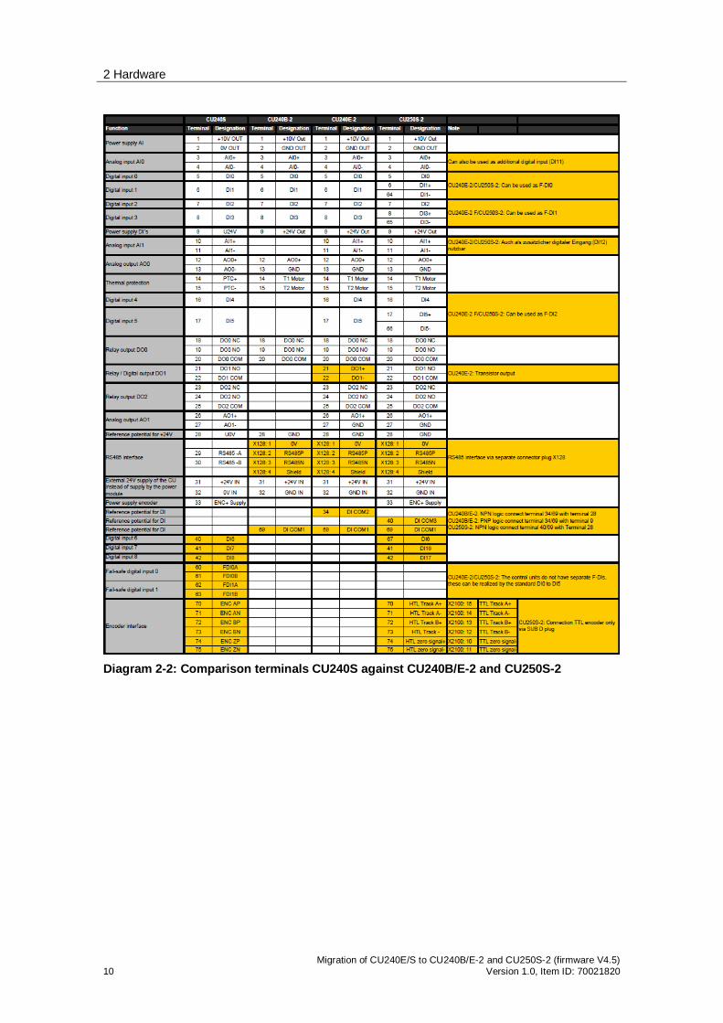
Diagram 2-2: Comparison terminals CU240S against CU240B/E-2 and CU250S-2
3 Encoder connection
Migration of CU240E/S to CU240B/E-2 and CU250S-2 (firmware V4.5) Version 1.0, Item-ID: 70021820 11
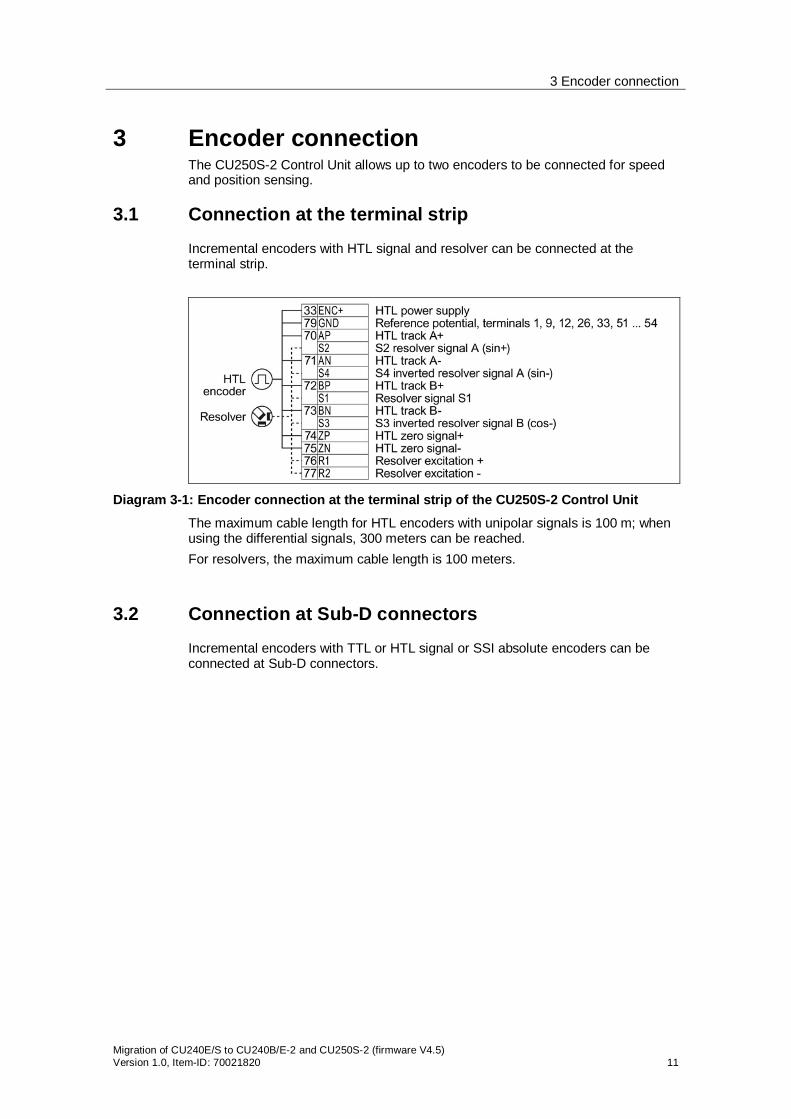
3 Encoder connection The CU250S-2 Control Unit allows up to two encoders to be connected for speed and position sensing.
3.1 Connection at the terminal strip
Incremental encoders with HTL signal and resolver can be connected at the terminal strip.
Diagram 3-1: Encoder connection at the terminal strip of the CU250S-2 Control Unit
The maximum cable length for HTL encoders with unipolar signals is 100 m; when using the differential signals, 300 meters can be reached. For resolvers, the maximum cable length is 100 meters.
3.2 Connection at Sub-D connectors
Incremental encoders with TTL or HTL signal or SSI absolute encoders can be connected at Sub-D connectors.

3 Encoder connection
12 Migration of CU240E/S to CU240B/E-2 and CU250S-2 (firmware V4.5)
Version 1.0, Item ID: 70021820
Diagram 3-2: Encoder connection at the Sub-D connector of the CU250S-2 Control Unit
The maximum cable length for HTL encoders with unipolar signals is 100 m; when using the differential signals, 300 meters can be reached. When using TTL encoders, a maximum cable length of 100 meters is possible. SSI absolute encoders can be connected with cables up to 100 meters long.
3.3 Connection with Drive-CLiQ
The CU250S-2 Control Unit has a Drive-CLiQ connection, to which all Drive-CLiQ encoders and encoder modules can be connected. Possible encoder types:
Resolver HTL/TTL incremental encoder SIN/COS incremental encoder Endat absolute encoder SSI absolute encoder Drive-CLiQ encoder
Drive-CLiQ modules that can be connected: SMC10 for 2 and multi-pole resolvers SMC20 for SIN/COS incremental encoders, Endat absolute encoders, SSI
absolute encoders with SIN/COS incremental signal SMC30 for TTL/HTL incremental encoders, SSI absolute encoders
with/without TTL/HTL signals SME20 for incremental measuring systems SME25 for absolute measuring systems SME120 for incremental measuring systems SME125 for absolute measuring systems

3 Encoder connection
Migration of CU240E/S to CU240B/E-2 and CU250S-2 (firmware V4.5) Version 1.0, Item-ID: 70021820 13
3.4 Combination of encoders for speed and position control
For the CU250S-2 Control Unit in the vector control mode, one encoder can be used for speed control, and a second encoder for position control.
Position control
Speed control Sub-D Terminals Drive-CLiQ
Without encoder
TTL/ HTL SSI Resolver HTL TTL/HTL SSI Resolver EnDat DQ
encoder
Without encoder -
Sub-D TTL/HTL
SSI
Terminals Resolver
HTL
Drive-CLiQ
TTL/HTL
SSI
Resolver
EnDat
DQ encoder
Diagram 3-3: Possibility of combining encoders for speed and position sensing
4 BOP-2 and IOP operator panels
14 Migration of CU240E/S to CU240B/E-2 and CU250S-2 (firmware V4.5)
Version 1.0, Item ID: 70021820
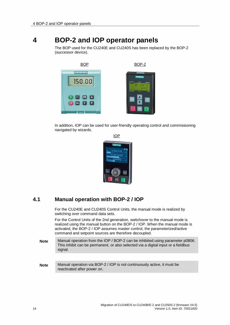
4 BOP-2 and IOP operator panels The BOP used for the CU240E and CU240S has been replaced by the BOP-2 (successor device). BOP BOP-2
In addition, IOP can be used for user-friendly operating control and commissioning navigated by wizards. IOP
4.1 Manual operation with BOP-2 / IOP
For the CU240E and CU240S Control Units, the manual mode is realized by switching over command data sets. For the Control Units of the 2nd generation, switchover to the manual mode is realized using the manual button on the BOP-2 / IOP. When the manual mode is activated, the BOP-2 / IOP assumes master control, the parameterized/active command and setpoint sources are therefore decoupled.
Note Manual operation from the IOP / BOP-2 can be inhibited using parameter p0806. This inhibit can be permanent, or also selected via a digital input or a fieldbus signal.
Note Manual operation via BOP-2 / IOP is not continuously active, it must be reactivated after power on.
4 BOP-2 and IOP operator panels
Migration of CU240E/S to CU240B/E-2 and CU250S-2 (firmware V4.5) Version 1.0, Item-ID: 70021820 15
4.2 Status signals of the BOP-2 / IOP operating elements
The BOP-2 and IOP operator panels behave, from the control side, just the same as a computer with the STARTER operating control software. BiCo linking to control words is no longer available.
Note The BOP-2 / IOP operating elements can no longer be used via the BOP control word r0019 as BICO sources as for the CU240E and CU240S.

5 Parameterization
16 Migration of CU240E/S to CU240B/E-2 and CU250S-2 (firmware V4.5)
Version 1.0, Item ID: 70021820
5 Parameterization A direct migration from projects with CU240E and CU240S to 2nd generation Control Units is not possible as a result of the modified parameter structure.
Note The drive must be recommissioned using BOP-2, IOP or STARTER.
5.1 Quick commissioning
The functional scope of parameter p0010 "Drive commissioning filter" has been expanded.
Parameter Action P0010 0: Ready
1: Quick commissioning 2. Power unit commissioning 3. Motor commissioning 4: Encoder commissioning 5: Technological applications/units 11: Function modules 15: Data sets 17. Basic positioning commissioning 25: Closed-loop position control commissioning 29: Only internal Siemens 30: Parameter reset 95: Safety Integrated commissioning
Diagram 5-1: Versions of the quick commissioning
5.2 User-defined parameters
The "user-defined parameters" function with 20 freely-definable customer parameters has been replaced by the know-how protection function. The know-how protection is used, for example, so that a machine manufacturer can encrypt his configuration know-how and protect it against changes or copying. The know-how protection is available in the following versions:
Know-how protection without copy protection (possible with or without memory card)
Know-how protection with copy protection (possible only with Siemens memory card)
A password is required for the know-how protection. In case of active know-how protection, the STARTER dialog screens are locked. You can, however, read the values of the display parameters from the expert list. The values of the adjustment parameters are not displayed and cannot be changed. Actions listed below can be executed even when know-how protection is active:
Restoring factory settings Confirming messages Displaying messages

5 Parameterization
Migration of CU240E/S to CU240B/E-2 and CU250S-2 (firmware V4.5) Version 1.0, Item-ID: 70021820 17
Displaying the alarm history Reading out diagnostic buffer Switching to the control panel (complete control panel functionality: Fetch
master control, all buttons and setting parameters) Upload (only parameters that are accessible even though know-how
protection is active) Actions listed below cannot be executed when know-how protection is active:
Download Export/Import Trace Function generator Measuring functions Automatic controller setting Stationary/rotating measurement Deleting the alarm history
5.3 Macro drive unit
The pre-assignment of Control Unit terminals using macro parameter p0700 "Select command source", p1000 "Select frequency setpoint and combination parameter p0719" and "Select command and setpoint source" is replaced by the macro saved in parameter p0015.
5.3.1 CU240B-2 Control Unit
The CU240B-2 and CU240B-2 DP Control Units offer the following default settings for its interfaces:

5 Parameterization
18 Migration of CU240E/S to CU240B/E-2 and CU250S-2 (firmware V4.5)
Version 1.0, Item ID: 70021820
Diagram 5-2: Overview of the connection macros of the CU240B-2 Control Unit
For the CU240B-2, the factory setting includes macro 12 "Two-wire control according to method 1", and for the CU240B-2 DP, macro 7 "Fieldbus/jog mode.
5.3.2 CU240E-2 Control Unit
The family of CU240E-2 Control Units offers the following default settings for the interfaces:

5 Parameterization
Migration of CU240E/S to CU240B/E-2 and CU250S-2 (firmware V4.5) Version 1.0, Item-ID: 70021820 19

5 Parameterization
20 Migration of CU240E/S to CU240B/E-2 and CU250S-2 (firmware V4.5)
Version 1.0, Item ID: 70021820
Diagram 5-3: Overview of the connection macros of the CU240E-2 Control Unit
The following factory settings are preassigned: CU240E-2 Macro 12 "Two wire control according to method 1" CU240E-2 F Macro 12 "Two wire control according to method 1" CU240E-2 DP Macro 7 "Fieldbus/jog mode" CU240E-2 PN Macro 7 "Fieldbus/jog mode" CU240E-2 DP-F Macro 7 "Fieldbus/jog mode"
5 Parameterization
Migration of CU240E/S to CU240B/E-2 and CU250S-2 (firmware V4.5) Version 1.0, Item-ID: 70021820 21
CU240E-2 PN-F Macro 7 "Fieldbus/jog mode"
5.3.3 CU250S-2 Control Unit

5 Parameterization
22 Migration of CU240E/S to CU240B/E-2 and CU250S-2 (firmware V4.5)
Version 1.0, Item ID: 70021820
5 Parameterization
Migration of CU240E/S to CU240B/E-2 and CU250S-2 (firmware V4.5) Version 1.0, Item-ID: 70021820 23
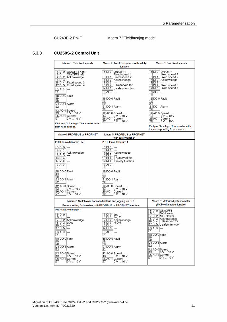
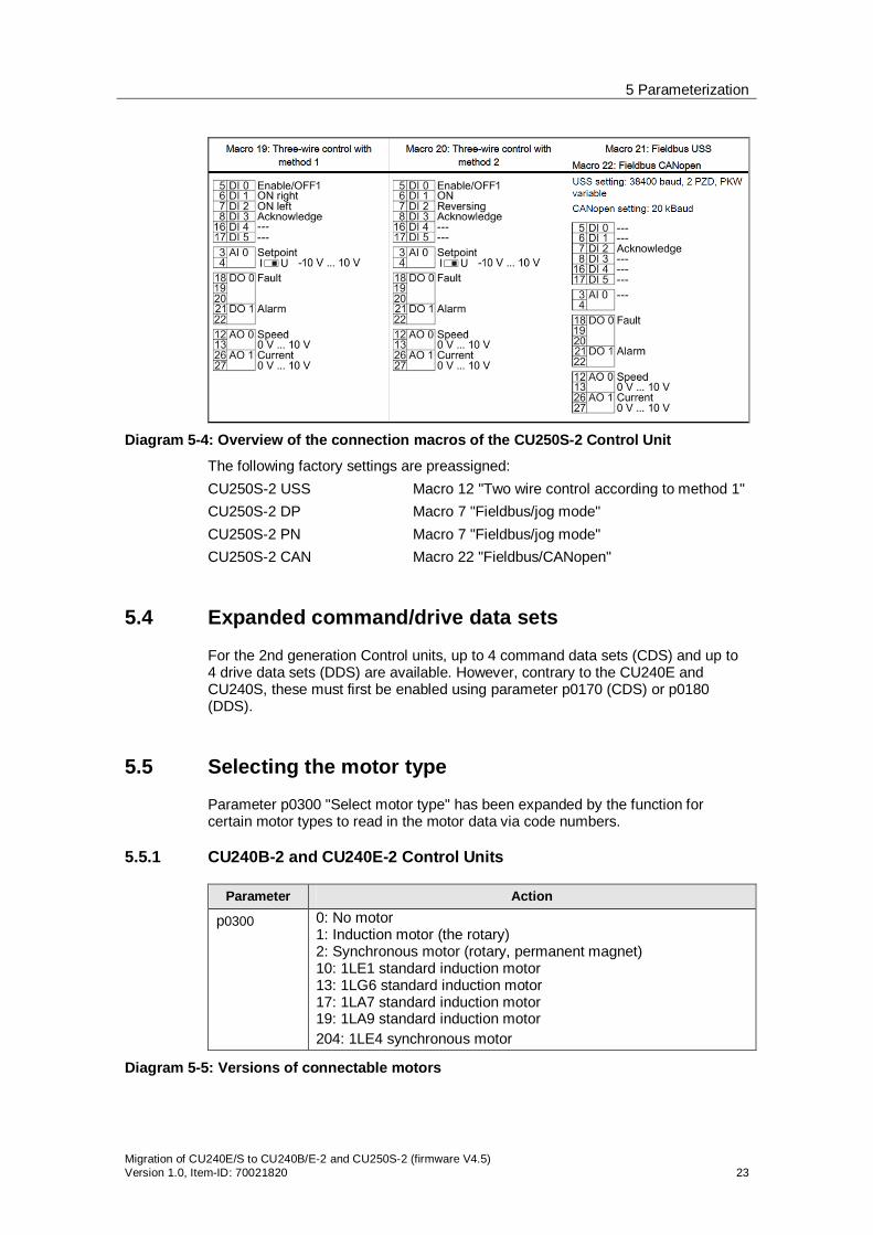
Diagram 5-4: Overview of the connection macros of the CU250S-2 Control Unit
The following factory settings are preassigned: CU250S-2 USS Macro 12 "Two wire control according to method 1" CU250S-2 DP Macro 7 "Fieldbus/jog mode" CU250S-2 PN Macro 7 "Fieldbus/jog mode" CU250S-2 CAN Macro 22 "Fieldbus/CANopen"
5.4 Expanded command/drive data sets
For the 2nd generation Control units, up to 4 command data sets (CDS) and up to 4 drive data sets (DDS) are available. However, contrary to the CU240E and CU240S, these must first be enabled using parameter p0170 (CDS) or p0180 (DDS).
5.5 Selecting the motor type
Parameter p0300 "Select motor type" has been expanded by the function for certain motor types to read in the motor data via code numbers.
5.5.1 CU240B-2 and CU240E-2 Control Units
Parameter Action
p0300 0: No motor 1: Induction motor (the rotary) 2: Synchronous motor (rotary, permanent magnet) 10: 1LE1 standard induction motor 13: 1LG6 standard induction motor 17: 1LA7 standard induction motor 19: 1LA9 standard induction motor 204: 1LE4 synchronous motor
Diagram 5-5: Versions of connectable motors

5 Parameterization
24 Migration of CU240E/S to CU240B/E-2 and CU250S-2 (firmware V4.5)
Version 1.0, Item ID: 70021820
A motor can be selected from the motor parameter list using parameter p0300. When changing the code number (exception, to a value of zero), all motor parameters are preassigned from the parameter lists internally available.
Note Only code numbers of motors can be set, which correspond to the motor type selected in p0300.
5.5.2 CU250S-2 Control Unit
Parameter Action
p0300 0: No motor 1: Induction motor (the rotary) 2: Synchronous motor (rotary, permanent magnet) 10: 1LE1 standard induction motor series 13: 1LG6 standard induction motor series 17: 1LA7 standard induction motor series 19: 1LA9 standard induction motor series 100: 1LE1 standard induction motor 104: 1PH4 induction motor 107: 1PH7 induction motor 108: 1PH8 induction motor
Diagram 5-6: Versions of connectable motors
A motor can be selected from the motor parameter list using parameter p0300. When changing the code number (exception, to a value of zero), all motor parameters are preassigned from the parameter lists internally available.
Note Only code numbers of motors can be set, which correspond to the motor type selected in p0300.
5.6 Selecting the encoder type
For the CU250S-2 Control Unit, various encoder types can be connected. When connecting TTL and HTL incremental encoders usual for the CU240S Control Unit, new settings must be observed.
Parameter Action
p0400 3001: 1024 HTL A/B R 3002: 1024 TTL A/B R 3003: 2048 HTL A/B R 3005: 1024 HTL A/B 3006: 1024 TTL A/B 3007: 2048 HTL A/B 3008: 2048 TTL A/B 3009: 1024 HTL A/B unipolar 3011: 2048 HTL A/B unipolar 9999: user-defined
Diagram 5-7: Selecting incremental encoders that can be connected
Different incremental encoders can be entered, user-defined using parameters p0401 to p0487.
5 Parameterization
Migration of CU240E/S to CU240B/E-2 and CU250S-2 (firmware V4.5) Version 1.0, Item-ID: 70021820 25
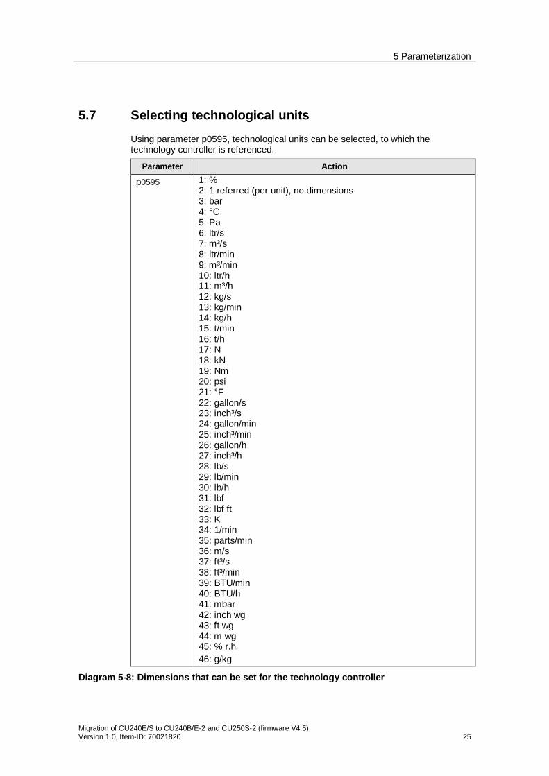
5.7 Selecting technological units
Using parameter p0595, technological units can be selected, to which the technology controller is referenced.
Parameter Action
p0595 1: % 2: 1 referred (per unit), no dimensions 3: bar 4: °C 5: Pa 6: ltr/s 7: m³/s 8: ltr/min 9: m³/min 10: ltr/h 11: m³/h 12: kg/s 13: kg/min 14: kg/h 15: t/min 16: t/h 17: N 18: kN 19: Nm 20: psi 21: °F 22: gallon/s 23: inch³/s 24: gallon/min 25: inch³/min 26: gallon/h 27: inch³/h 28: lb/s 29: lb/min 30: lb/h 31: lbf 32: lbf ft 33: K 34: 1/min 35: parts/min 36: m/s 37: ft³/s 38: ft³/min 39: BTU/min 40: BTU/h 41: mbar 42: inch wg 43: ft wg 44: m wg 45: % r.h. 46: g/kg
Diagram 5-8: Dimensions that can be set for the technology controller

5 Parameterization
26 Migration of CU240E/S to CU240B/E-2 and CU250S-2 (firmware V4.5)
Version 1.0, Item ID: 70021820
Technological values can be internally scaled to 100% using parameter p0596.
5.8 Operating hours counter
Using p0650, the actual operating hours can be read out and a maintenance interval activated in p0651. Alarm A1590 is activated after the time in p0651 elapses.
5.9 Digital inputs
5.9.1 CU240B/E-2 Control Unit
The potential of the digital inputs of the control unit CU240B-2 and CU240E-2 can be defined by the wiring of the inputs. For internal power supply
P-switching (PNP logic): Connect terminals 34 and 69 with terminal 28 M-switching (NPN logic): Connect terminals 34 and 69 with terminal 9
For an external power supply P-switching (PNP logic: Connect terminals 34 and 69 with the system
ground (GND) M-switching (NPN logic): Connect terminals 34 and 69 with the 24 V
supply.
Diagram 5-9: Function diagram, digital inputs of the CU240B-2 Control Unit
For the CU240E-2 Control Unit, in addition, the reference potential is divided into two terminals (DI COM and DI COM2).
Terminal 69 (DI COM): Reference potential for DI0, DI2 and DI4

5 Parameterization
Migration of CU240E/S to CU240B/E-2 and CU250S-2 (firmware V4.5) Version 1.0, Item-ID: 70021820 27
Terminal 34 (DI COM2): Reference potential for DI1, DI3 and DI5 With this configuration fail-safe digital inputs (F-DI) of the control unit CU240E-2 and CU240E-2 F can be realized both p-switching or p- and m-switching.
Diagram 5-10: Function diagram, digital inputs of the CU240E-2 Control Unit
5.9.2 CU250S-2 Control Unit
The digital inputs of the control unit CU250S-2 are divided into two potential sections: - DI0 to DI6 with reference potential DI COM 1 - DI16 to DI19 with reference potential DI COM 3.

5 Parameterization
28 Migration of CU240E/S to CU240B/E-2 and CU250S-2 (firmware V4.5)
Version 1.0, Item ID: 70021820
Diagram 5-11: Function diagram, digital inputs DI0 to DI6 of the CU250S-2 Control Unit
The digital inputs DI1, DI3, and DI5 have separate lead through (-) inputs. Using the digital inputs as fail-safe inputs switching to P24V (p-switching) the wiring according diagram 5-11 must be taken. If the fail-safe input shall be designed with one input switching to P24V (p-switching) and the other digital input switching to ground (m-switching), the positive inputs (+) inputs of DI1, DI3, and DI5 have to be connected to P24V, the negative (-) input of DI1, DI3, and DI5 is switched against DI COM 1. Besides the 7 digital inputs DI0 to DI6 with the potential DI COM1 there are another 4 digital inputs DI16 to DI19 with an own potential DI COM3. These digital inputs can be used as the digital inputs of the control units CU240B-2 and CU240E-2 as well as p-switching and also m-switching.

5 Parameterization
Migration of CU240E/S to CU240B/E-2 and CU250S-2 (firmware V4.5) Version 1.0, Item-ID: 70021820 29
Diagram 5-12: Function diagram, digital inputs DI16 to DI19 of the CU250S-2 Control Unit
5.9.3 Forward/backward parameterization
For CU240E and CU240S Control Units, it was possible to wire the digital inputs directly via parameter p0701 to p0706 to specified functions forwards, and on the other side, using the BiCo wiring (selection p0701… p0706 = 99) to wire them backwards as required. For 2nd generation modules, forwards wiring is no longer possible; the digital inputs are wired in the required functions using display parameters r0722.0 … 27. In addition, the inverted inputs are available in parameters r0723.0 … 27.
5.9.4 Change relating to fail-safe inputs (F-DI)
Contrary to the CU240S family, 2nd generation Control units have no separate fail-safe inputs. For 2nd generation Control Units, the F-DI are formed from two standard DI
CU240E-2: 2 standard inputs as 1 F-DI CU240E-2 F: 6 standard inputs as 3 F-DI CU250S-2: 6 standard inputs as 3 F-DI
5.9.5 Transferring the status of F-DI via PROFIsafe
When using PROFIsafe, for 2nd generation Control Units, the status of the F-DI can be transferred fail-safe to the F-CPU, which means that they are available as distributed F I/O. This applies both for Control Units with PROFBUS, PROFINET and Safety Integrated as well as also the CU240E-2 DP Control Unit.
5 Parameterization
30 Migration of CU240E/S to CU240B/E-2 and CU250S-2 (firmware V4.5)
Version 1.0, Item ID: 70021820
5.9.6 Simulation Mode
The digital inputs and outputs can be simulated using parameter p0795.x.
STARTER The digital inputs and outputs can be set to the simulation state in the STARTER operating software.
Diagram 5-13: Simulation of the digital inputs/outputs using STARTER
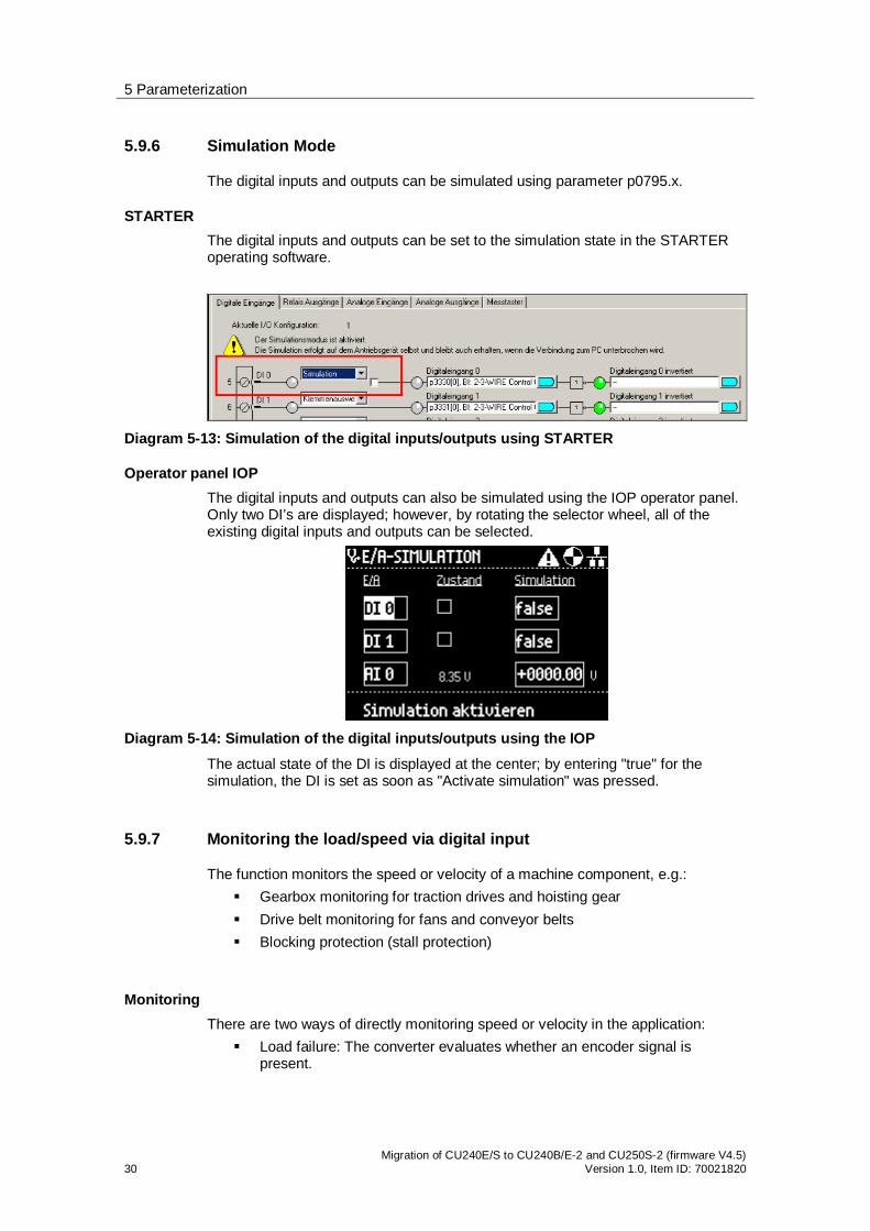
Operator panel IOP The digital inputs and outputs can also be simulated using the IOP operator panel. Only two DI’s are displayed; however, by rotating the selector wheel, all of the existing digital inputs and outputs can be selected.
Diagram 5-14: Simulation of the digital inputs/outputs using the IOP
The actual state of the DI is displayed at the center; by entering "true" for the simulation, the DI is set as soon as "Activate simulation" was pressed.
5.9.7 Monitoring the load/speed via digital input
The function monitors the speed or velocity of a machine component, e.g.: Gearbox monitoring for traction drives and hoisting gear Drive belt monitoring for fans and conveyor belts Blocking protection (stall protection)
Monitoring There are two ways of directly monitoring speed or velocity in the application:
Load failure: The converter evaluates whether an encoder signal is present.

5 Parameterization
Migration of CU240E/S to CU240B/E-2 and CU250S-2 (firmware V4.5) Version 1.0, Item-ID: 70021820 31
Speed deviation: The converter calculates a speed from the signal of the connected encoder and compares it with the motor speed.
A sensor (e.g. a proximity switch) is required for speed monitoring. The converter evaluates the sensor signal via a digital input.
Load failure
Diagram 5-15: Load failure monitoring using a digital input
Diagram 5-16: Parameterization of the load monitoring via digital input
Speed deviation This function is only available for CU240E-2… Control Units. The monitoring sensor must be connected to digital input 3. The converter can process a pulse sequence of up to 32 kHz.
Diagram 5-17: Speed deviation monitoring
The speed is calculated from the pulse signal of the digital input in the "probe". The converter compares the calculated speed with the speed actual value r2169. The converter response if the deviation is too high, can be adjusted using p2181.
5 Parameterization
32 Migration of CU240E/S to CU240B/E-2 and CU250S-2 (firmware V4.5)
Version 1.0, Item ID: 70021820
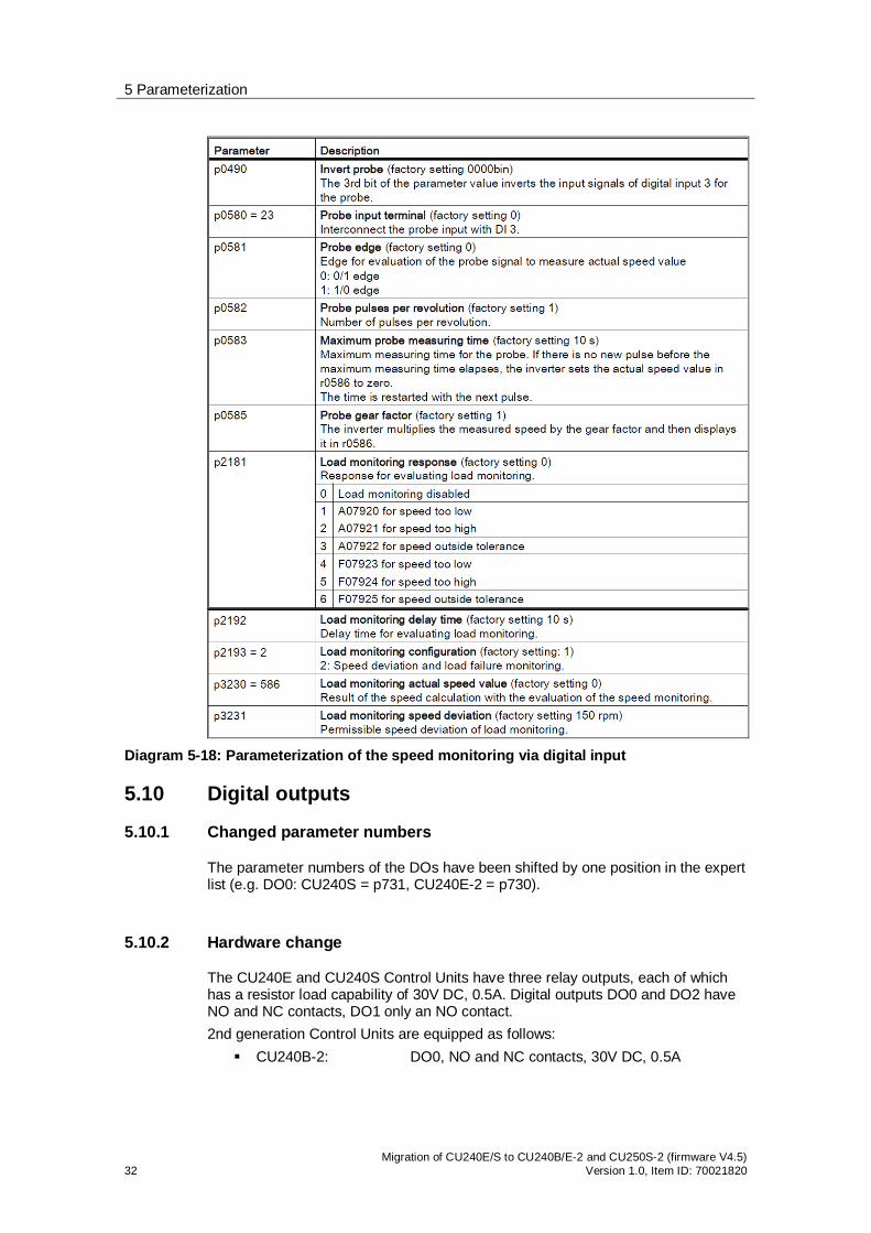
Diagram 5-18: Parameterization of the speed monitoring via digital input
5.10 Digital outputs
5.10.1 Changed parameter numbers
The parameter numbers of the DOs have been shifted by one position in the expert list (e.g. DO0: CU240S = p731, CU240E-2 = p730).
5.10.2 Hardware change
The CU240E and CU240S Control Units have three relay outputs, each of which has a resistor load capability of 30V DC, 0.5A. Digital outputs DO0 and DO2 have NO and NC contacts, DO1 only an NO contact. 2nd generation Control Units are equipped as follows:
CU240B-2: DO0, NO and NC contacts, 30V DC, 0.5A
5 Parameterization
Migration of CU240E/S to CU240B/E-2 and CU250S-2 (firmware V4.5) Version 1.0, Item-ID: 70021820 33
CU240E-2: DO0, NO and NC contacts, 30 V DC, 0.5A DO1, transistor output positive, 30 V DC, 0.5A DO2, NO and NC contacts, 30 V DC, 0.5A
CU250S-2: DO0, NO and NC contacts, 30 V DC, 0.5A DO1, NO contact, 30 V DC, 0.5A DO2, NO and NC contacts, 30 V DC, 0.5A
5.11 Analog inputs
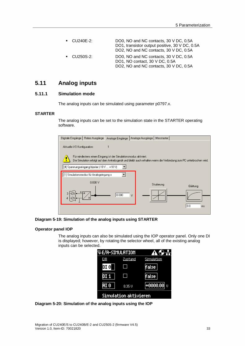
5.11.1 Simulation mode
The analog inputs can be simulated using parameter p0797.x.
STARTER The analog inputs can be set to the simulation state in the STARTER operating software.
Diagram 5-19: Simulation of the analog inputs using STARTER
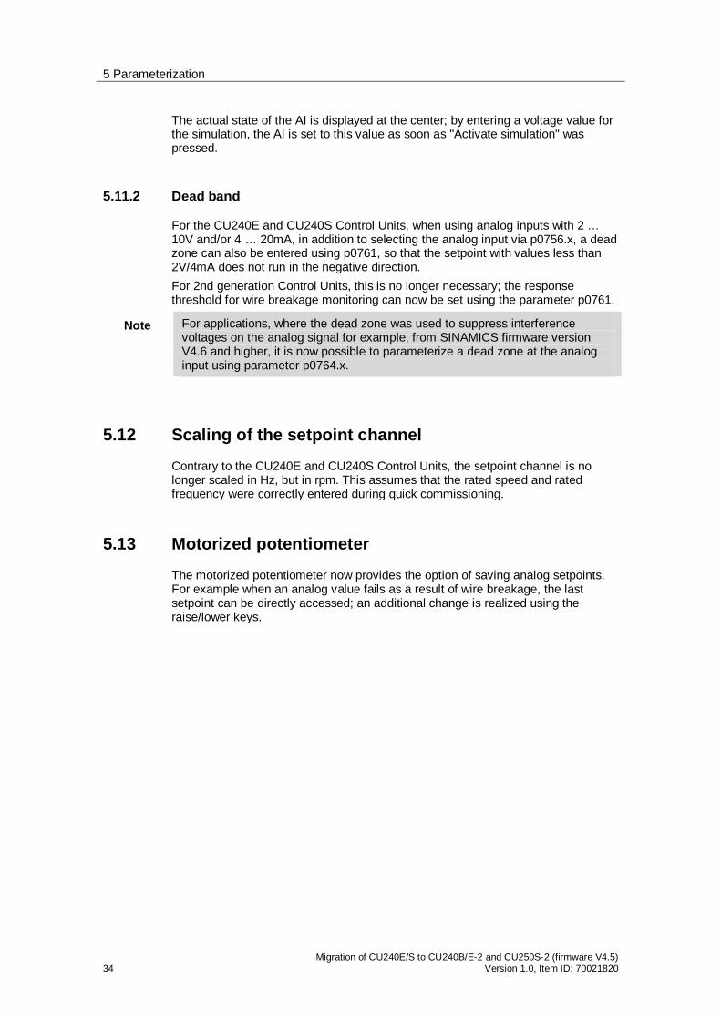
Operator panel IOP The analog inputs can also be simulated using the IOP operator panel. Only one DI is displayed; however, by rotating the selector wheel, all of the existing analog inputs can be selected.
Diagram 5-20: Simulation of the analog inputs using the IOP
5 Parameterization
34 Migration of CU240E/S to CU240B/E-2 and CU250S-2 (firmware V4.5)
Version 1.0, Item ID: 70021820
The actual state of the AI is displayed at the center; by entering a voltage value for the simulation, the AI is set to this value as soon as "Activate simulation" was pressed.
5.11.2 Dead band
For the CU240E and CU240S Control Units, when using analog inputs with 2 … 10V and/or 4 … 20mA, in addition to selecting the analog input via p0756.x, a dead zone can also be entered using p0761, so that the setpoint with values less than 2V/4mA does not run in the negative direction. For 2nd generation Control Units, this is no longer necessary; the response threshold for wire breakage monitoring can now be set using the parameter p0761.
Note For applications, where the dead zone was used to suppress interference voltages on the analog signal for example, from SINAMICS firmware version V4.6 and higher, it is now possible to parameterize a dead zone at the analog input using parameter p0764.x.
5.12 Scaling of the setpoint channel
Contrary to the CU240E and CU240S Control Units, the setpoint channel is no longer scaled in Hz, but in rpm. This assumes that the rated speed and rated frequency were correctly entered during quick commissioning.
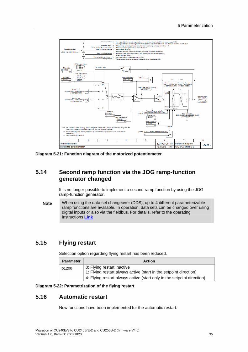
5.13 Motorized potentiometer
The motorized potentiometer now provides the option of saving analog setpoints. For example when an analog value fails as a result of wire breakage, the last setpoint can be directly accessed; an additional change is realized using the raise/lower keys.
5 Parameterization
Migration of CU240E/S to CU240B/E-2 and CU250S-2 (firmware V4.5) Version 1.0, Item-ID: 70021820 35
Diagram 5-21: Function diagram of the motorized potentiometer
5.14 Second ramp function via the JOG ramp-function generator changed
It is no longer possible to implement a second ramp function by using the JOG ramp-function generator.
Note When using the data set changeover (DDS), up to 4 different parameterizable ramp functions are available. In operation, data sets can be changed over using digital inputs or also via the fieldbus. For details, refer to the operating instructions Link
5.15 Flying restart
Selection option regarding flying restart has been reduced.
Parameter Action
p1200 0: Flying restart inactive 1: Flying restart always active (start in the setpoint direction) 4: Flying restart always active (start only in the setpoint direction)
Diagram 5-22: Parametrization of the flying restart
5.16 Automatic restart
New functions have been implemented for the automatic restart.

5 Parameterization
36 Migration of CU240E/S to CU240B/E-2 and CU250S-2 (firmware V4.5)
Version 1.0, Item ID: 70021820
Parameter Action
p1210 0: Inhibited automatic restart 1: Acknowledge all faults without restarting 4: Restart after line supply failure, without additional start attempts 6: Restart after fault with additional start attempts 14: Restart after line failure after manual acknowledgment 16: Restart after fault after manual acknowledgment 26: Acknowledging all faults and restarting for an ON command
Diagram 5-23: Setting options for automatic restart
Up to 10 fault messages can be set using parameter p1206, where the automatic restart is not started.
5.17 Expanded motor holding brake function
The parameterization of the motor holding brake has been expanded. Now, there are various modes available where the brake can be opened and closed as before from the process, however also permanently or depending on an external signal.
Note Only the CU250S-2 Control Unit supports the SBC safety function (Safe Brake Control).
5.18 Setting dynamic braking
For 2nd generation Control units, the braking module is automatically activated when using a PM240. The braking resistor must be externally protected against overload.
Thermo sensors of the braking resistor are wired to a DI of the converter, and this input is interconnected with parameter p2106 "External fault 1". As a consequence, for an overtemperature, fault F07860 "External fault 1" is activated.
Note When using a braking resistor, the VDCmax controller should be deactivated (for vector control: p1240 = 0, for U/f: p1280 = 0).
From firmware version V4.6 and higher, parameter p0219 is available, which can be used to define the maximum permissible braking power. This parameter automatically sets the regenerative power and the down ramp, further, it inhibits the Vdcmax controller.
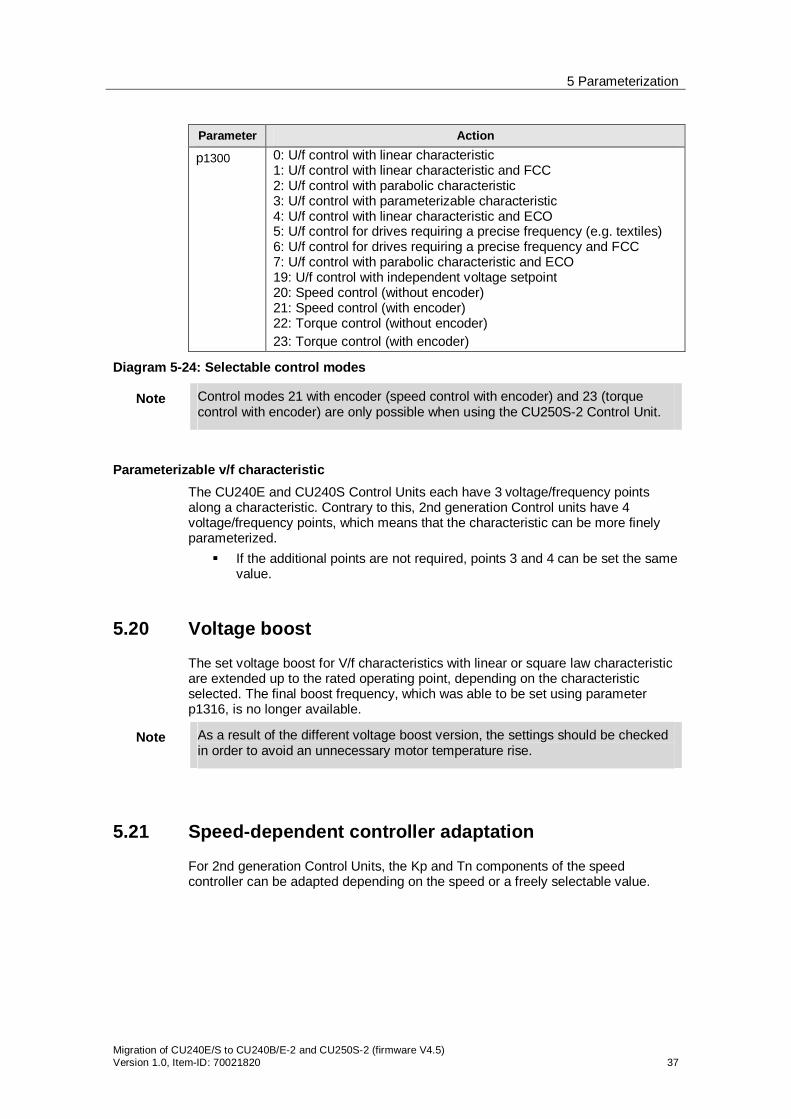
5.19 Control modes
Control modes Selecting the control modes using parameter p1300 has been supplemented by ECO versions with flux reduction.
5 Parameterization
Migration of CU240E/S to CU240B/E-2 and CU250S-2 (firmware V4.5) Version 1.0, Item-ID: 70021820 37
Parameter Action
p1300 0: U/f control with linear characteristic 1: U/f control with linear characteristic and FCC 2: U/f control with parabolic characteristic 3: U/f control with parameterizable characteristic 4: U/f control with linear characteristic and ECO 5: U/f control for drives requiring a precise frequency (e.g. textiles) 6: U/f control for drives requiring a precise frequency and FCC 7: U/f control with parabolic characteristic and ECO 19: U/f control with independent voltage setpoint 20: Speed control (without encoder) 21: Speed control (with encoder) 22: Torque control (without encoder) 23: Torque control (with encoder)
Diagram 5-24: Selectable control modes
Note Control modes 21 with encoder (speed control with encoder) and 23 (torque control with encoder) are only possible when using the CU250S-2 Control Unit.
Parameterizable v/f characteristic The CU240E and CU240S Control Units each have 3 voltage/frequency points along a characteristic. Contrary to this, 2nd generation Control units have 4 voltage/frequency points, which means that the characteristic can be more finely parameterized.
If the additional points are not required, points 3 and 4 can be set the same value.
5.20 Voltage boost
The set voltage boost for V/f characteristics with linear or square law characteristic are extended up to the rated operating point, depending on the characteristic selected. The final boost frequency, which was able to be set using parameter p1316, is no longer available.
Note As a result of the different voltage boost version, the settings should be checked in order to avoid an unnecessary motor temperature rise.
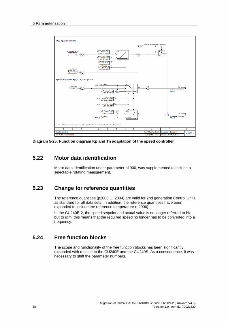
5.21 Speed-dependent controller adaptation
For 2nd generation Control Units, the Kp and Tn components of the speed controller can be adapted depending on the speed or a freely selectable value.
5 Parameterization
38 Migration of CU240E/S to CU240B/E-2 and CU250S-2 (firmware V4.5)
Version 1.0, Item ID: 70021820
Diagram 5-25: Function diagram Kp and Tn adaptation of the speed controller
5.22 Motor data identification
Motor data identification under parameter p1900, was supplemented to include a selectable rotating measurement.
5.23 Change for reference quantities
The reference quantities (p2000 … 2004) are valid for 2nd generation Control Units as standard for all data sets. In addition, the reference quantities have been expanded to include the reference temperature (p2006). In the CU240E-2, the speed setpoint and actual value is no longer referred to Hz but to rpm; this means that the required speed no longer has to be converted into a frequency.
5.24 Free function blocks
The scope and functionality of the free function blocks has been significantly expanded with respect to the CU240E and the CU240S. As a consequence, it was necessary to shift the parameter numbers.

5 Parameterization
Migration of CU240E/S to CU240B/E-2 and CU250S-2 (firmware V4.5) Version 1.0, Item-ID: 70021820 39
Diagram 5-26: Scope of the free function blocks
In the specified time slices (runtime groups), the free function blocks can be parameterized with a defined execution sequence.
5.25 Technology controller
The technology controller was expanded to implement normal as well as inverse control operations.
Normal control sense: As long as the actual value is less than the setpoint, a positive system deviation results in a positive drive speed.
Inverse control sense: As long as the actual value is greater than the setpoint, a positive system deviation results in a positive drive speed.
Parameter p2306 is used to change over the control sense.
5.26 Fixed setpoints that can be freely used
Using parameters p2900 and p2901, fixed setpoints that can be freely used, can be defined in the range +/- 100.00%. Further, permanently defined fixed setpoints are already available in r2902 [0 … 14].
5 Parameterization
40 Migration of CU240E/S to CU240B/E-2 and CU250S-2 (firmware V4.5)
Version 1.0, Item ID: 70021820
5.27 Change, deactivating the BF-LED
If a fieldbus is not being used, then the BF-LED can be deactivated using parameter p2030 0. For more detailed information, see Link
5.28 Wobbulation generator has been eliminated
The wobbulation generator available in the CU240E and CU240S is no longer available.
5.29 Positioning down ramp has been eliminated
The positioning down ramp available in the CU240E and CU240S (parameters p2480 ... p2488) is no longer available.
Implemented using rapid traverse/crawl changeover based on free function blocks.
5.30 Memory card
Contrary to the CU240S, where only MMC cards were able to be used, MMC and SD cards can now be used.
5.30.1 Transferring projects using a memory card
CU240S projects on an MMC card can no longer be transferred to a CU240B/E-2 or CU250S-2 as a result of the modified parameter structure.
5.30.2 Handling memory cards
Writing to MMC / SD cards has been significantly simplified. Parameter changes are automatically saved on the memory card. For details, see operating instructions in Chapter 4.6 Link and FAQ Link

6 Performance vector control
Migration of CU240E/S to CU240B/E-2 and CU250S-2 (firmware V4.5) Version 1.0, Item-ID: 70021820 41
6 Performance vector control 6.1 Vector control without encoder SLVC (sensorless)
Diagram 6-1: Comparison of the control performance for CU240S and CU240B/E-2, CU250S-2 for vector control without encoder
We do not recommend using torque control without encoder, instead, speed control can be used with torque limiting.

6 Performance vector control
42 Migration of CU240E/S to CU240B/E-2 and CU250S-2 (firmware V4.5)
Version 1.0, Item ID: 70021820
6.2 Vector control with encoder
Diagram 6-2: Comparison of the control performance for CU240S and CU250S-2 for vector control with encoder
6.3 Increased ruggedness of the vector control
For encoderless vector control of the CU240S, for critical applications, such as raising and lowering, the motor data had to be optimized a multiple number of times, taking into account equivalent circuit diagram data. Tests carried out on gantry cranes indicated that the equivalent circuit diagram data for the CU240E-2 Control Units were precisely determined with the first MotID, so that post optimization was no longer required. This indicated that the vector control of the SINAMICS pool is significantly more stable than the vector control of the old software pool.

7 Communication
Migration of CU240E/S to CU240B/E-2 and CU250S-2 (firmware V4.5) Version 1.0, Item-ID: 70021820 43
7 Communication Existing programs to control a SINAMICS G120 with CU240S via fieldbus from a PLC, can, in most cases, be reused for 2nd generation Control Units. Adaptation using changed parameter numbers may be required, only if parameters are accessed via cyclic or acyclic communication. Safety programs in an F-CPU must be appropriately adapted to use the new extended safety functions (see Chapter 8)
7.1 GSD files
New GSG files are required for the 2nd generation Control Units. These can be downloaded at the following link Link
7.2 Routing through a CPU
For routing across network boundaries (IE to Profibus DP), the CPU must support the data set routing protocol. In addition, as before DriveES Basic is required, also STARTER from version V4.3 with Service Pack SP2. The following CPUs support data set routing:
- ET200S IM151-8 PN/DP CPU in conjunction with DP master module
- SIMATIC S7-300 CPU313C-2 DP from version V3.3 CPU314C-2 DP from version V3.3 CPU314C-2 PN/DP from version V3.3 CPU315-2 DP from version V3.0 CPU315-2 PN/DP from version V3.1 CPU317-2 DP from version V3.3 CPU317-2 PN/DP from version V3.1 CPU319-3 PN/DP from version V2.7
- SIMATIC S7-400 CPUs from version V5.1 - WinAC RTX from version 2010, update 1 with CP5603,
CP5613 or CP5623 Presently, the following systems do not support data set routing:
- SIMATIC S7-1200 - WinAC MP - SIMOTION

7 Communication
44 Migration of CU240E/S to CU240B/E-2 and CU250S-2 (firmware V4.5)
Version 1.0, Item ID: 70021820
7.3 Teleservice
7.3.1 Teleservice via a CPU
Diagram 7-1: Teleservice via a SIMATIC CPU
For this, a Teleservice Adapter II and a CPU listed under routing (see Chapter 7.2), which supports data set routing, are required.

7 Communication
Migration of CU240E/S to CU240B/E-2 and CU250S-2 (firmware V4.5) Version 1.0, Item-ID: 70021820 45
7.3.2 Teleservice directly via the fieldbus
Diagram 7-1: Teleservice via fieldbus
For this configuration, the Teleservice Adapter is directly connected at the fieldbus. In this case, it is of no significance whether the CPU supports data set routing.
For Control Units with PROFINET connection CU240E-2 PN and CU250S-2 PN, Teleservice is possible via Teleservice Adapter IE Basic.
Note For PROFIBUS, teleservice is presently not possible, as Teleservice Adapter II does not support the functionality.
7.4 Slave-to-slave communication (direct data exchange) New function With "Slave-slave communication" (also called "Data Exchange Broadcast") it is possible to quickly exchange data between converters (slaves) without the master being directly involved, for instance, to use the actual value of one converter as setpoint for other converters (for more detailed information, see the operating instructions (Chapter 6.1.4.4) Link.
7.5 Direct HMI connection
Directly connecting an HMI to read out and change drive parameters, without intermediate CPU, is not supported.
Note The parameters must be read out of the converter by the CPU, and from there, transferred to the HMI.
8 Safety functions
46 Migration of CU240E/S to CU240B/E-2 and CU250S-2 (firmware V4.5)
Version 1.0, Item ID: 70021820
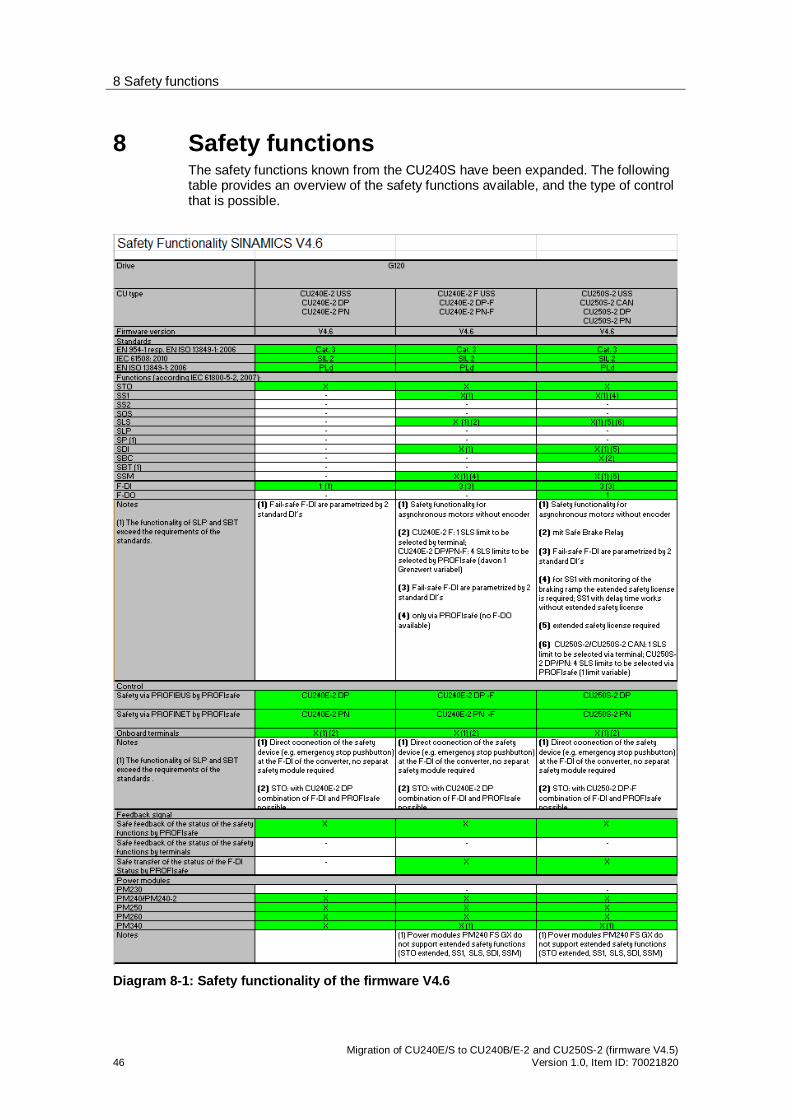
8 Safety functions The safety functions known from the CU240S have been expanded. The following table provides an overview of the safety functions available, and the type of control that is possible.
Diagram 8-1: Safety functionality of the firmware V4.6
8 Safety functions
Migration of CU240E/S to CU240B/E-2 and CU250S-2 (firmware V4.5) Version 1.0, Item-ID: 70021820 47
You can find more detailed information on the safety functions in the Safety Integrated Function Manual, Link or on the following Internet page Link
Note As before, for the safety functions speed sensing using a speed encoder is not required. STO is permissible for all applications, where Emergency Stop functionality is stipulated. SS1, SLS, SSM and SDI are not permissible for pulling and continuously regenerative loads (also refer to the Safety Integrated Function Manual, Chapter 2.2 Link ). The F-DIs are formed by combining 2 standard DIs per parameterization.
8.1 New and extended safety functions
8.1.1 Extended SS1 (Safe Stop 1)
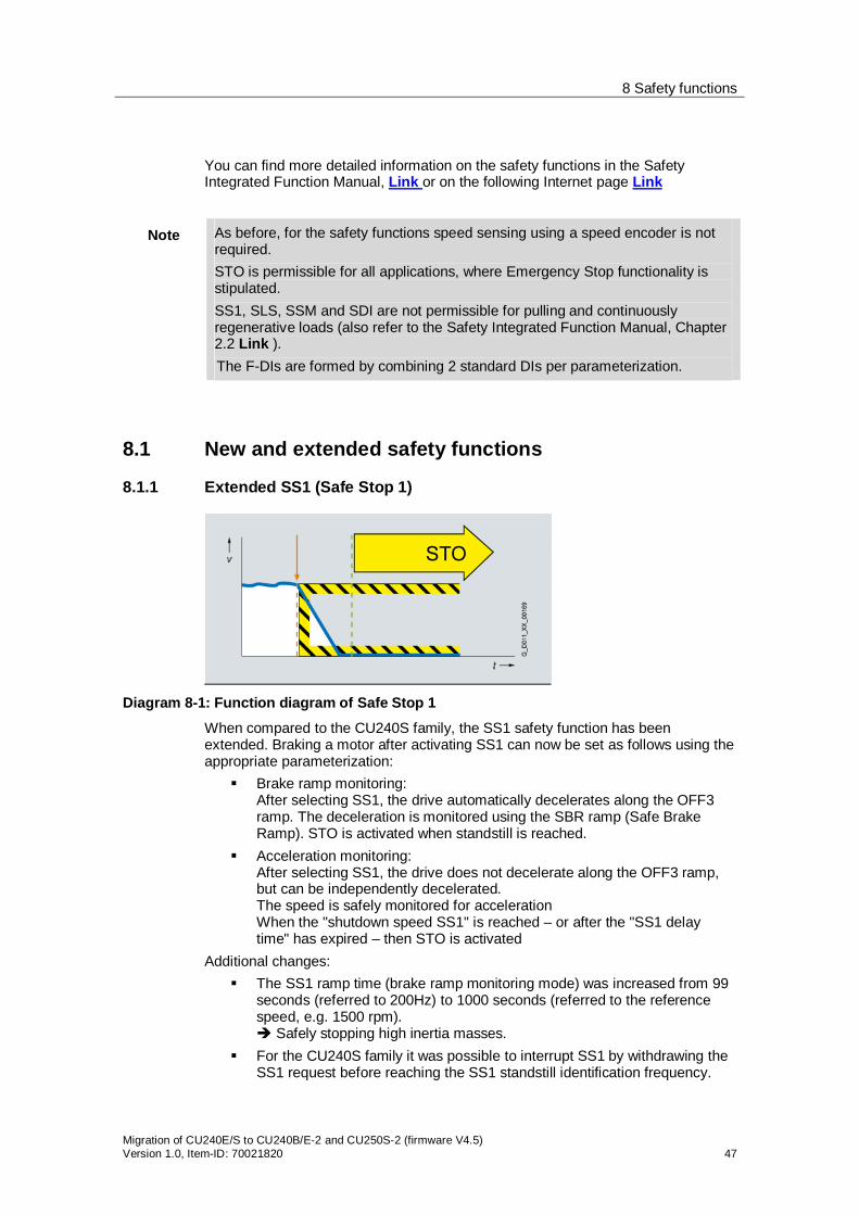
Diagram 8-1: Function diagram of Safe Stop 1 When compared to the CU240S family, the SS1 safety function has been extended. Braking a motor after activating SS1 can now be set as follows using the appropriate parameterization:
Brake ramp monitoring: After selecting SS1, the drive automatically decelerates along the OFF3 ramp. The deceleration is monitored using the SBR ramp (Safe Brake Ramp). STO is activated when standstill is reached.
Acceleration monitoring: After selecting SS1, the drive does not decelerate along the OFF3 ramp, but can be independently decelerated. The speed is safely monitored for acceleration When the "shutdown speed SS1" is reached – or after the "SS1 delay time" has expired – then STO is activated
Additional changes: The SS1 ramp time (brake ramp monitoring mode) was increased from 99
seconds (referred to 200Hz) to 1000 seconds (referred to the reference speed, e.g. 1500 rpm).
Safely stopping high inertia masses. For the CU240S family it was possible to interrupt SS1 by withdrawing the
SS1 request before reaching the SS1 standstill identification frequency.

8 Safety functions
48 Migration of CU240E/S to CU240B/E-2 and CU250S-2 (firmware V4.5)
Version 1.0, Item ID: 70021820
This is no longer possible for CU240E-2 and CU250S-2. The SS1 request remains until STO is internally activated.

8 Safety functions
Migration of CU240E/S to CU240B/E-2 and CU250S-2 (firmware V4.5) Version 1.0, Item-ID: 70021820 49
8.1.2 Extension of SLS (Safely Limited Speed)
Diagram 8-2: Function diagram, safely limited speed
When compared to the CU240S family, the SLS safety function has been extended as follows:
The various SLS modes of the CU240S family have, for the CU240E-2 and the CU250S-2, been integrated to form one "mode". This simplifies commissioning and allows new safety concepts to be implemented.
With the CU240E-2 DP F, CU240E-2 PN-F, CU250S-2 DP and the CU250S-2 PN, when controlled via PROFIsafe, 4 parameterizable SLS limit values are available. New safety concepts can be implemented.
When activating SLS at standstill, the motor must be fed with current within 5 seconds. Reaching a minimum speed during this 5s, as was the case for the CU240S family, is no longer required. This simplifies the control.
The drive response when activating SLS (automatic or manual deceleration) can be set using the SS1 brake ramp or acceleration monitoring.
When SLS is active, the response to a limit value violation can be selected to either be STOP A (STO) and STOP B (SS1) (for CU240S, only STO is possible) In the case of a fault, the motor can now be safely braked and no longer coasts down unbraked.
8.1.3 New safety function SDI (Safe Direction)
Diagram 8-3: Function diagram, safe direction
The safety function prevents the motor operating in an unsafe direction of rotation. An encoder is not required for this safety function.
New safety concepts can be implemented, e.g. remaining in a hazardous area while a system part is moved out of this dangerous area – or setting-up operation with a safely inhibited direction of rotation.
8 Safety functions
50 Migration of CU240E/S to CU240B/E-2 and CU250S-2 (firmware V4.5)
Version 1.0, Item ID: 70021820
8.1.4 New safety function SSM (Safe Speed Monitor)
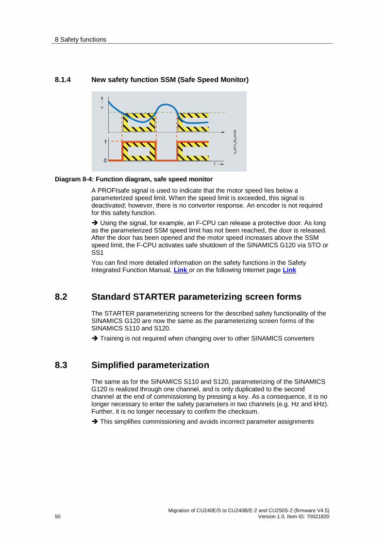
Diagram 8-4: Function diagram, safe speed monitor
A PROFIsafe signal is used to indicate that the motor speed lies below a parameterized speed limit. When the speed limit is exceeded, this signal is deactivated; however, there is no converter response. An encoder is not required for this safety function.
Using the signal, for example, an F-CPU can release a protective door. As long as the parameterized SSM speed limit has not been reached, the door is released. After the door has been opened and the motor speed increases above the SSM speed limit, the F-CPU activates safe shutdown of the SINAMICS G120 via STO or SS1 You can find more detailed information on the safety functions in the Safety Integrated Function Manual, Link or on the following Internet page Link
8.2 Standard STARTER parameterizing screen forms
The STARTER parameterizing screens for the described safety functionality of the SINAMICS G120 are now the same as the parameterizing screen forms of the SINAMICS S110 and S120.
Training is not required when changing over to other SINAMICS converters
8.3 Simplified parameterization
The same as for the SINAMICS S110 and S120, parameterizing of the SINAMICS G120 is realized through one channel, and is only duplicated to the second channel at the end of commissioning by pressing a key. As a consequence, it is no longer necessary to enter the safety parameters in two channels (e.g. Hz and kHz). Further, it is no longer necessary to confirm the checksum.
This simplifies commissioning and avoids incorrect parameter assignments
8 Safety functions
Migration of CU240E/S to CU240B/E-2 and CU250S-2 (firmware V4.5) Version 1.0, Item-ID: 70021820 51
8.4 Offline safety parameter assignment
Just the same as for SINAMICS S110 and S120, safety functions can now also be parameterized offline.
The safety parameterization can now already be prepared in an office environment.
8.5 Acceptance report
Using the STARTER parameterizing software, an acceptance report of the safety functions can be generated, in which all of the relevant parameter values are automatically entered
Can be found in STARTER under the drive unit in the documentation folder The text for the acceptance report is based on an application by scripting, see Link.
8.6 Changing the reference quantity
Speed-related safety values no longer refer to Hz but to rpm. In addition, a gearbox factor can be parameterized
Therefore, it is no longer necessary to convert the parameterization to the resulting motor speed.
8.7 Group drives
The STO, SS1, SLS, SDI and SSM safety functions can be used in conjunction with group drives (where more than one motor is fed from one converter).

8 Safety functions
52 Migration of CU240E/S to CU240B/E-2 and CU250S-2 (firmware V4.5)
Version 1.0, Item ID: 70021820
8.8 Changes to the PROFIsafe telegram
The PROFIsafe telegram has been extended as a result of the more extensive safety functions of the CU240E-2 family. The safety program of the F-CPU must be appropriately extended in order to be able to use these functions.
8.8.1 Previous CU240E/S PROFIsafe telegram 30
* Selects whether byte 0 / bit 4 or byte 1 / bit 0 should be used for the SLS control, is realized via the parameterization
8.8.2 New CU240B/E-2, CU250S-2 PROFIsafe telegram 30
* Extended Safety functions (CU240E-2 –F, CU240E-2 DP-F and CU240E-2 PN-F)
Changes to the CU240S PROFIsafe telegram (control word)
Byte 0 / bit 4 SLS control exclusively via this bit New: Byte 0 / bit 7 Acknowledgment signal for safety error
messages New: Byte 1 / bit 1 and 2 Selects SLS limit value 1..4 New: Byte 1 / bit 4 and 4 Selects the appropriate safe direction of
rotation Changes to the CU240S PROFIsafe telegram (status word)
Byte 0 / bit 4 Speed below SLS limit value, exclusively via this bit New: Byte 0 / bit 7 Safety function error New: Byte 1 / bit 1 and 2 Feedback signal, active SLS limit value 1..4 New: Byte 1 / bit 4 and 4 Feedback signal activation of safe direction
of rotation New: Byte 1 / bit 7 Feedback signal status SSM

8 Safety functions
Migration of CU240E/S to CU240B/E-2 and CU250S-2 (firmware V4.5) Version 1.0, Item-ID: 70021820 53
8.8.3 New CU240B/E-2, CU250S-2 PROFIsafe telegram 900
* Extended Safety functions (CU240E-2 –F, CU240E-2 DP-F and CU240E-2 PN-F)
PROFIsafe telegram 900 differs from the PROFIsafe telegram 30 in so much that for this telegram, the status of the fail-safe digital inputs is also transferred (byte 3, bit 0…2)
8.9 Transferring the status of F-DI via PROFIsafe
New function When using PROFIsafe, for the CU240E-2 DP-F, CU240E-2 PN-F, CU250S-2 DP and the CU250S-2 PN, the status of the F-DIs can be transferred to the F-CPU in a fail-safe fashion; they are therefore available to this as distributed F I/O.

9 Drive fault messages
54 Migration of CU240E/S to CU240B/E-2 and CU250S-2 (firmware V4.5)
Version 1.0, Item ID: 70021820
9 Drive fault messages The fault messages of the 2nd generation Control Units have changed with respect to the CU240E and CU240S. If these are to be displayed at an HMI for diagnostic purposes, then the corresponding fault texts can be downloaded from the following link Link. In addition, it is now possible to hide certain fault messages or convert them into alarms. The acknowledgment mode can also be adapted.
Diagram 9-1: Function diagram, fault/alarm configuration