sin 482 - bt plc · sin 482 issue 1.14 british telecommunications plc page 4 of 39 1. introduction...
TRANSCRIPT

British Telecommunications plc
Registered Office 81 Newgate Street LONDON EC1A 7AJ
Registered in England no.1800000
SIN 482 Issue 1.14
December 2015
Suppliers' Information Note
For The BT Network
BT IPstream Connect
Service Description Each SIN is the copyright of British Telecommunications plc. Reproduction of the SIN is permitted only in its
entirety, to disseminate information on the BT Network within your organisation. You must not edit or amend
any SIN or reproduce extracts. You must not remove BT trade marks, notices, headings or copyright markings.
This document does not form a part of any contract with BT customers or suppliers.
Users of this document should not rely solely on the information in this document, but should carry out their
own tests to satisfy themselves that terminal equipment will work with the BT network.
BT reserves the right to amend or replace any or all of the information in this document.
BT shall have no liability in contract, tort or otherwise for any loss or damage, howsoever arising from use of, or
reliance upon, the information in this document by any person.
Due to technological limitations, a very small percentage of customer interfaces may not comply with some of
the individual characteristics, which may be defined in this document.
Publication of this Suppliers' Information Note does not give or imply any licence to any intellectual property
rights belonging to British Telecommunications plc or others. It is your sole responsibility to obtain any
licences, permissions or consents which may be necessary if you choose to act on the information supplied in
the SIN.
Those BT services marked indicates it is a registered trade mark of British Telecommunications plc.
Those BT services marked indicates it is a trade mark of British Telecommunications plc.
This SIN is available in Portable Document Format (pdf) from: http://www.btplc.com/sinet/
Enquiries relating to this document should be directed to: [email protected]

SIN 482 Issue 1.14 British Telecommunications plc Page 2 of 39
CONTENTS
1. INTRODUCTION .......................................................................................................................................... 4
2. AVAILABILITY ............................................................................................................................................. 5
3. SERVICE OUTLINE ...................................................................................................................................... 6
3.1 OVERVIEW .................................................................................................................................................. 6 3.2 END USER ACCESS COMPONENTS ................................................................................................................. 7 3.3 IPSTREAM CONNECT HANDOVER COMPONENT .............................................................................................. 9
3.3.1 Overview ......................................................................................................................................... 9 3.3.2 Commercial arrangements .............................................................................................................. 9 3.3.3 IPstream Connect Handover interconnect options: ....................................................................... 10 3.3.4 Features of the Handover Component ........................................................................................... 11 3.3.5 Physical presentation .................................................................................................................... 13 3.3.6 Routing Protocols .......................................................................................................................... 13 3.3.7 Handover Link Tagging ................................................................................................................. 14
4. END USER AUTHENTICATION AND ESTABLISHING A PPP SESSION ............................................... 15
4.1 GENERAL .................................................................................................................................................. 15 4.2 AUTHENTICATION OPTIONS........................................................................................................................ 16
4.2.1 Default Accept, PTA mode ............................................................................................................ 16 4.2.2 PTA Mode with authentication / SID authentication ..................................................................... 17 4.2.3 Always PPP passthrough (L2TP) with BT selected tunnel end point ............................................. 19 4.2.4 Mixed SSN, PTA or L2TP determined by CP .................................................................................. 19
4.3 RADIUS ACCOUNTING OPTIONS ................................................................................................................. 21 4.4 RADIUS SETUP AND ROUTING .................................................................................................................... 23 4.5 RADIUS STANDARDS ................................................................................................................................ 23 4.6 PRESENTATION DOMAIN (HOW THE DOMAIN IS PRESENTED TO THE SERVICE PROVIDER) .................................. 24
4.6.1 Format Options ............................................................................................................................. 24 4.6.2 Username and Domain Name length ............................................................................................ 25
4.7 TEST USER ACCOUNT ................................................................................................................................ 25 4.8 SESSION HANDLING UNDER FAILURE ........................................................................................................... 25 4.9 PPPOE SUPPORT AND MTU SIZE ................................................................................................................ 26
5. IPSTREAM CONNECT DIAGNOSTIC OPTIONS ...................................................................................... 27
5.1 GENERAL .................................................................................................................................................. 27 5.2 XDSL IP TEST ........................................................................................................................................... 27 5.3 PERFORMANCE TESTER .............................................................................................................................. 28
6. REFERENCES ............................................................................................................................................. 33
7. ABBREVIATIONS ...................................................................................................................................... 33
8. HISTORY .................................................................................................................................................... 36
TABLES
Table 1 End User Components – ADSL Technology ............................................................................................ 8
Table 2 End User Components – SDSL Technology ............................................................................................ 9
Table 3 Connectivity Locations ........................................................................................................................... 10
Table 4 Authentication Request Format .............................................................................................................. 17
Table 5 Access Accept Message Attributes (PTA Mode with authentication / SID authentication) ................... 18
Table 6 Access Request Attributes (Mixed SSN, PTA or L2TP determined by CP) .......................................... 20
Table 7 Access Accept Message Attributes (Mixed SSN, PTA or L2TP determined by CP) ............................. 20
Table 8 RADIUS Accounting Data Format ......................................................................................................... 22

SIN 482 Issue 1.14 British Telecommunications plc Page 3 of 39
FIGURES
Figure 1. End to End Service Overview ................................................................................................................ 5
Figure 2. Access Products and Handover Links .................................................................................................... 7
Figure 3. xDSL IP test for end user where PPP session is terminated on the BRAS ........................................... 27
Figure 4. xDSL IP test for L2TP end users, where CP has opted into end to end diagnostics ............................ 28
Figure 5. Performance test “TAP1” for PTA end users ....................................................................................... 29
Figure 6. Performance test “TAP1” for L2TP end users ..................................................................................... 30
Figure 7. Performance test “TAP2”, connecting to optional test LNS within the CP’s network ......................... 31
Figure 8. Performance test “TAP3” ..................................................................................................................... 32

SIN 482 Issue 1.14 British Telecommunications plc Page 4 of 39
1. Introduction
This Suppliers’ Information Note (SIN) provides service description information about BT IPstream Connect. The IPstream Connect product is a new interconnect option for Communications Providers. It forms part of BT’s Internet Protocol (IP) Transport Services portfolio (SIN 302).
This SIN should be read in conjunction with SIN 302 detailing BT's Internet Protocol (IP) Transport Services, SIN 485 detailing BT IPstream Connect Office, Home, Max and Max Premium products, and SIN 487 detailing BT IPstream Connect Symmetric. If required, this SIN should also be read in conjunction with SIN 496 detailing SID into RADIUS Authentication, SIN 497 detailing SID into RADIUS Accounting and SIN 502 detailing Session Steering.
The following definitions apply throughout this document:
Customer: The Communications Provider (CP) who purchases the BT IPstream Connect service from BT and sells or provides it to End Users. Also referred to as ISP (Internet Service Provider) to differentiate from Content Service Provider.
End User: The person using a device (e.g. PC) to connect to a CP’s IP network via the BT IPstream Connect service.
BT Wholesale has launched a product that provides the option to pick up broadband traffic at the IPstream Broadband Remote Access Server (BRAS) node. The interconnect at the BRAS node forms a new Equivalence of Input (EoI) point within the service, in addition to the existing EoI point for IPstream consuming SMPF from Openreach. The original end to end IPstream service is still available, although it has been re-engineered to consume the IPstream Connect interconnect products at the BRAS node.
The IPstream Connect product is made up of two components, the End User Access and the Handover.
The IPstream Connect product gives CP customers the option to take broadband end user traffic off at the BRAS node (via the IPstream Connect Handover component) and transport it to their own or a third party backhaul network.
In creating the IPstream Connect product, it is BTW’s intention to keep the IPstream Connect end user access the same as the existing IPstream end user access where regulatory and commercial drivers permit. All of the features listed below are features of the current IPstream End User access product.
The following diagram supplies an End to End service overview of the IPstream Connect product

SIN 482 Issue 1.14 British Telecommunications plc Page 5 of 39
Figure 1. End to End Service Overview
All BT IPstream Connect products are provided on shared infrastructure. The BT IPstream Connect Office /BT IPstream Connect Max Premium products have priority, through the shared part of the BT IPstream Connect network, over the BT IPstream Connect Home /BT IPstream Connect Max products. During a busy period a BT IPstream Connect office or BT IPstream Connect Max Premium product will receive a higher downstream throughput than the equivalent BT IPstream Connect Home or BT IPstream Connect Max product.
BT IPstream Connect Home, Office, Max and Max Premium products present an auto-sensing PPP layer – this will automatically configure itself to the PPP protocol and encapsulation presented by the End User’s equipment. The supported combinations are: PPPoA VC-mux, PPPoA LLC/SNAP, PPPoE LLC/SNAP. See SIN 485 for more detail.
The BT IPstream Connect Symmetric service offers a symmetric IP connectivity between Customers and their End Users providing a wires only SHDSL interface. See SIN 487 for more detail.
BT IPstream Connect enables a Customer to access multiple End Users via interconnects with the BT network at 10 locations. The Customer owns the sales, marketing and recruitment of End Users and the contractual/service relationship. BT supplies the delivery transport and basic service.
For further information on the commercial aspects of this service, please refer to:
Your BT Account Manager
BT Broadband Helpdesk via e-mail to: [email protected]
BT Broadband Helpdesk on 0800 0283663
ADSL website http://www.btwholesale.com > Broadband community
BT Wholesale website http://www.btwholesale.com
BT Terms website http://www.bt.com/terms
If you have inquiries relating to this document, then please contact: [email protected]
2. Availability

SIN 482 Issue 1.14 British Telecommunications plc Page 6 of 39
The BT IPstream Connect End User products are only available over BT provided PSTN Lines (including Wholesale Access). There are also technical reach limitations, which prevents ADSL-carried services being available to End Users beyond approximately 3.5 km from the local exchange for the BT IPstream Connect Home 2000 and BT IPstream Connect Office 2000 products, and beyond approximately 6 km for the BT IPstream Connect Home 1000 and BT IPstream Connect Office 1000 products. However, users on BT IPstream Connect Home 250, BT IPstream Connect Home 500 and BT IPstream Connect Office 500, BT IPstream Connect Max and BT IPstream Connect Max Premium products may be able to obtain service at greater distances from their local exchange.
During the initial order handling process, BT will check the suitability of the line for ADSL services and advise accordingly.
The products are only available in areas where BT has rolled out ADSL exchange equipment. See BT’s ADSL website http://www.btwholesale.com/broadband for availability.
Some existing telephony based services may be affected by the techniques used to deliver the BT IPstream Connect services over the same metallic line. These include:
30k loop
Private Circuits
ISDN - all types
Home Highway or Business Highway
ISDN - Digital Calls & Access
ISDN Connect
RedCarei
FeatureNet 5000 services
FeatureLine Hunt Groups
Meter Pulse Facility
PBX and AUX lines
We can only provide a single BT IPstream Connect service over a single PSTN exchange line.
End Users can only receive a single Broadband Service over a PSTN line.
Please note that this list is not exhaustive. We will endeavour to update this list as new information becomes available.
3. Service Outline
3.1 Overview
i Redcare is being made compatible with ADSL. Call the Redcare General Information Helpdesk on
0800 800 828 for the latest information.

SIN 482 Issue 1.14 British Telecommunications plc Page 7 of 39
BT IPstream Connect consists of a number of access products and the Handover Links.
Figure 2. Access Products and Handover Links
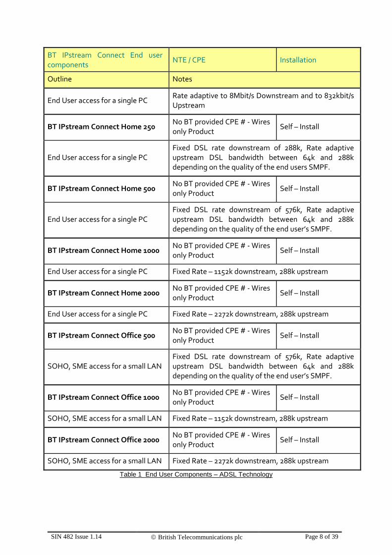
3.2 End User Access Components
BT IPstream Connect End user components provide the link that goes from an End User premises via a dedicated DSL line to the local exchange, to a BT Broadband Access Server in the BT network. The BT IPstream Connect product’s Network Termination Point is defined as the End Users-side of the Network Termination Equipment (NTE) installed by BT on the End User premises.
The End user components are provided using either:
ADSL technology which allows a Broadband service to co-exist with the End User’s BT provided PSTN (or Calls & Access) service.
Or
SDSL technology which requires a dedicated Metal Path Facility and cannot support PSTN service
BT IPstream Connect End user components
NTE / CPE Installation
Outline Notes
BT IPstream Connect Max No BT provided CPE # - Wires only Product
Self – Install
End User access for a single PC Rate adaptive to 8Mbit/s Downstream and to 448kbit/s Upstream
BT IPstream Connect Max Premium
No BT provided CPE # - Wires only Product
Self – Install
SIN 482 Issue 1.14 British Telecommunications plc Page 8 of 39
BT IPstream Connect End user components
NTE / CPE Installation
Outline Notes
End User access for a single PC Rate adaptive to 8Mbit/s Downstream and to 832kbit/s Upstream
BT IPstream Connect Home 250 No BT provided CPE # - Wires only Product
Self – Install
End User access for a single PC Fixed DSL rate downstream of 288k, Rate adaptive upstream DSL bandwidth between 64k and 288k depending on the quality of the end users SMPF.
BT IPstream Connect Home 500 No BT provided CPE # - Wires only Product
Self – Install
End User access for a single PC Fixed DSL rate downstream of 576k, Rate adaptive upstream DSL bandwidth between 64k and 288k depending on the quality of the end user’s SMPF.
BT IPstream Connect Home 1000 No BT provided CPE # - Wires only Product
Self – Install
End User access for a single PC Fixed Rate – 1152k downstream, 288k upstream
BT IPstream Connect Home 2000 No BT provided CPE # - Wires only Product
Self – Install
End User access for a single PC Fixed Rate – 2272k downstream, 288k upstream
BT IPstream Connect Office 500 No BT provided CPE # - Wires only Product
Self – Install
SOHO, SME access for a small LAN Fixed DSL rate downstream of 576k, Rate adaptive upstream DSL bandwidth between 64k and 288k depending on the quality of the end user’s SMPF.
BT IPstream Connect Office 1000 No BT provided CPE # - Wires only Product
Self – Install
SOHO, SME access for a small LAN Fixed Rate – 1152k downstream, 288k upstream
BT IPstream Connect Office 2000 No BT provided CPE # - Wires only Product
Self – Install
SOHO, SME access for a small LAN Fixed Rate – 2272k downstream, 288k upstream
Table 1 End User Components – ADSL Technology
SIN 482 Issue 1.14 British Telecommunications plc Page 9 of 39
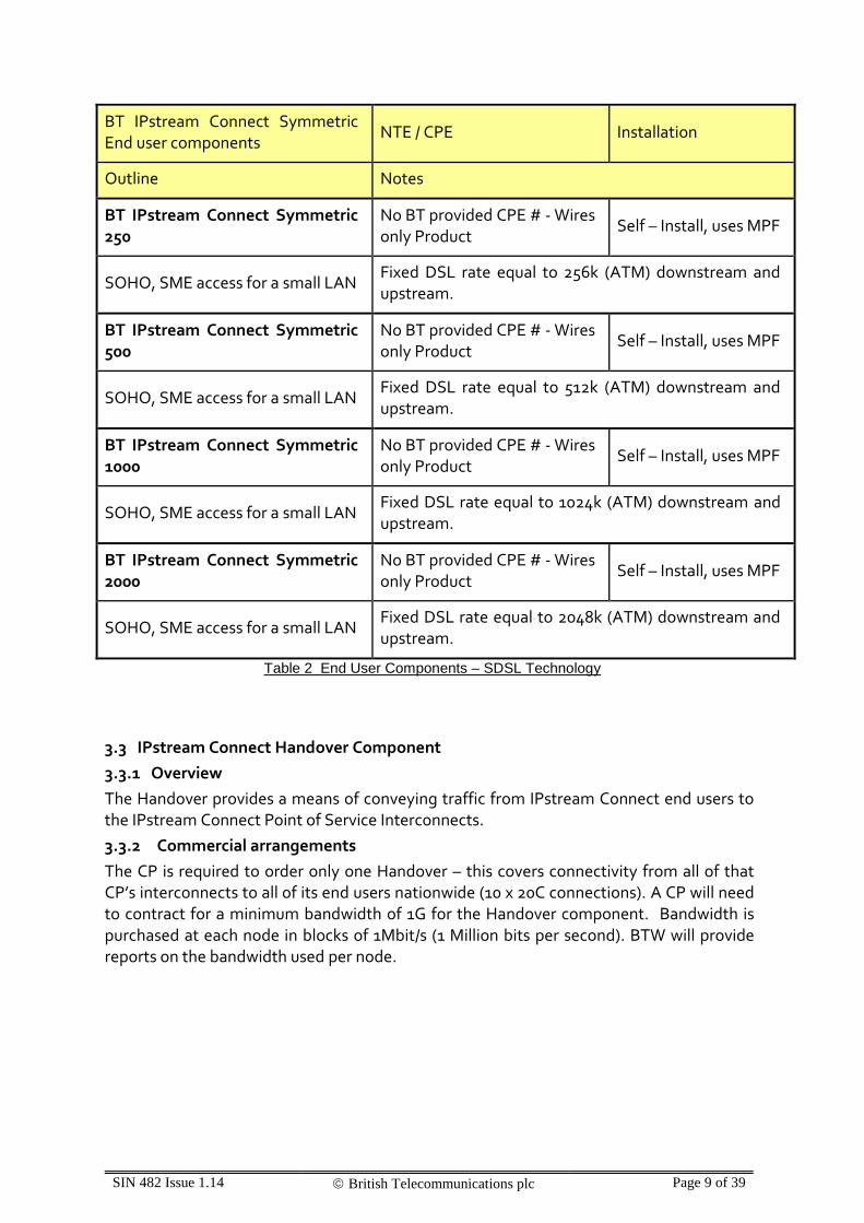
BT IPstream Connect Symmetric End user components
NTE / CPE Installation
Outline Notes
BT IPstream Connect Symmetric 250
No BT provided CPE # - Wires only Product
Self – Install, uses MPF
SOHO, SME access for a small LAN Fixed DSL rate equal to 256k (ATM) downstream and upstream.
BT IPstream Connect Symmetric 500
No BT provided CPE # - Wires only Product
Self – Install, uses MPF
SOHO, SME access for a small LAN Fixed DSL rate equal to 512k (ATM) downstream and upstream.
BT IPstream Connect Symmetric 1000
No BT provided CPE # - Wires only Product
Self – Install, uses MPF
SOHO, SME access for a small LAN Fixed DSL rate equal to 1024k (ATM) downstream and upstream.
BT IPstream Connect Symmetric 2000
No BT provided CPE # - Wires only Product
Self – Install, uses MPF
SOHO, SME access for a small LAN Fixed DSL rate equal to 2048k (ATM) downstream and upstream.
Table 2 End User Components – SDSL Technology
3.3 IPstream Connect Handover Component
3.3.1 Overview
The Handover provides a means of conveying traffic from IPstream Connect end users to the IPstream Connect Point of Service Interconnects.
3.3.2 Commercial arrangements
The CP is required to order only one Handover – this covers connectivity from all of that CP’s interconnects to all of its end users nationwide (10 x 20C connections). A CP will need to contract for a minimum bandwidth of 1G for the Handover component. Bandwidth is purchased at each node in blocks of 1Mbit/s (1 Million bits per second). BTW will provide reports on the bandwidth used per node.

SIN 482 Issue 1.14 British Telecommunications plc Page 10 of 39
The CP is required to purchase sufficient blocks of bandwidth to cover the bandwidth used by their end users. BTW will measure the bandwidth used by a CP per node. If the bandwidth used exceeds the bandwidth for which the CP has entered into contract, then they will incur a bursting bandwidth charge. BTW will have one charge for bandwidth, irrespective of the type of traffic passed (there are no IP DSCP priority marking specific charging schemes). BTW will not actively police the bandwidth to the contracted bandwidth purchased by the CP; it is the responsibility of the CP to ensure that if it wishes the bandwidth to be constrained or restricted then it will need to employ traffic management / control on its broadband traffic before the traffic enters BTW’s network.
3.3.3 IPstream Connect Handover interconnect options:
The EoI boundary for the IPstream Connect product is at the IPstream Connect BRAS nodes. Some of these nodes are not part of the 21C network whilst others are in buildings that serve both the legacy 20C IPstream network and the new 21C Network. To avoid forcing CPs to build out to legacy network locations and to help align the IPstream Connect product with WBC, BTW will provide the option of interconnect links between the legacy BRAS nodes and the nearest 21CN node. CPs wishing to purchase the IPstream Connect product therefore have the option of connecting at the BRAS nodes or connecting at the nearest 21C node. The following table summarises the connectivity locations:
20CN BRAS Node 21CN BB POSI Site
Kingston (SEC) Kingston (TEC)
Faraday Faraday
Ealing Colindale
Ilford Stepney
Reading Slough
Milton Keynes Milton Keynes
Birmingham Birmingham
Sheffield Sheffield
Manchester Manchester
Edinburgh (20C) Edinburgh (21C)
Table 3 Connectivity Locations

SIN 482 Issue 1.14 British Telecommunications plc Page 11 of 39
For each BRAS node the CP can choose to take a 20C connection option in the same building as the BRAS, in which case BTW will provide a connection to a suitable patch panel to facilitate the interconnection into the CP’s network, or the CP can choose to take a 21C connection option, in which case BTW will provide an interconnection between the 20C and 21C locations and interconnect to the CP’s MSIL product at the corresponding 21CN node. Any of the available MSIL variants can be used for the 21C connectivity option (e.g. in-span, in building handover). Please refer to the MSIL Product Handbook [7] for more details.
The CP is required to have some form of interconnect to all of the BRAS nodes to offer service to IPstream Connect end user accesses; this is via 10 x 20C connectivity.
In order to provide a resilient service, BTW will deploy two routers at each BRAS node in order to aggregate the traffic before presenting it for handover to a customer’s network. Where the CP takes a 20C connectivity option, the traffic will be presented over fibres from each of the routers. As such the service mandates that one or more pairs of fibres will be used for interconnection to the CP. The traffic over these fibres is carried in Ethernet running at 1Gbit/s or 10Gbit/s speeds. Where multiple pairs of fibres are used, Line Aggregation Group (LAG) can be selected to operate over the fibres from each router within the BTW network.
For the 21C connectivity option, the same rules apply for the speed and dimensioning of fibre interconnect and BTW will deploy 20CN to 21CN interconnect links in pairs. However, because the use of MSIL means that the L2 device connecting to each BTW BRAS aggregation router cannot be guaranteed to be the same device, it is not possible to offer a LAG option for the 21CN connectivity.
Although the product presents a pair of fibres at the 21CN interconnect node, the CP can elect to have the fibres connected into the same MSIL, or connected into separate MSIL’s. Traffic from a pair of interconnect links will be presented within a pair of IPstream Connect specific VLANs over the MSIL(s).
Notes:
1) There is a limit of 8x1G or 8x10G pairs of handover links at each handover node.
2) Due to the implications of a link failure if the links were not equal size, the CP must purchase handover links of equal size (1G or 10G) at a given handover node. It is not possible to mix sizes.
3.3.4 Features of the Handover Component
The Handover component is available in ‘PPP pass through’ and IP presentation options. For both variants, the CP is required to specify one or more Service Selection Names (SSNs) to associate with their infrastructure. This SSN enables BTW to map end users to the interconnect owned by the correct CP. The SSN is a character string that will be matched against the characters presented in the user-Id of the end user’s CHAP authentication request beyond the “@” symbol.

SIN 482 Issue 1.14 British Telecommunications plc Page 12 of 39
Example:
A user has its CPE router configured to login with a username and password.
If the username specified is [email protected], the bold characters equate to the service selection name (SSN).
The CP has the option of receiving RADIUS authentication and accounting packets for the IPstream Connect product. The service supports up to 3 CP Authentication RADIUS servers, and up to 2 Accounting RADIUS servers. The necessary details are captured on the RADIUS section of the Handover CRF.
If the CP does not wish to receive RADIUS authentication packets then BTW will take the following actions, depending on the SSN type:
- For SSNs configured as PTA mode only, the end user’s PPP setup requests will be default accepted and an IP address dynamically assigned to the end user from the CP’s pool on the end users BRAS.
- For SSNs configured as L2TP only, the end user’s PPP session will be tunnelled to one of the tunnel end points associated with that SSN. BTW will attempt to send an equal number of PPP sessions to each tunnel end point associated with an SSN.
- By their nature, mixed PTA and L2TP SSNs are not possible without a CP authentication RADIUS, as a RADIUS response is required to inform the BTW platform of the appropriate action to take for the end user. Similarly the PTA Mode Multiple Address Pool functionality (see Section 4) requires a CP authentication RADIUS.
If the CP wishes to receive RADIUS authentication packets, then each session setup request can be forwarded to the CP RADIUS. The CP RADIUS response can then be used to reject or accept the session, with the end user’s PPP session either tunnelled into the CP network or terminated on the BRAS depending on the exact nature of the RADIUS response. The CP is responsible for ensuring that there is a route from the IPstream Connect network to the CP’s RADIUS. The CP has the option of advertising a route to the RADIUS through one or more of the interconnects to the IPstream Connect network or using the internet to facilitate the connection.
The Premium Forwarding traffic class was introduced for Content Connect and uses the DSCP marking AF31. Any IPstream Connect traffic marked with AF31 will be re-marked by IPstream Connect as Best Efforts. In the case of L2TP traffic, the re-marking will be performed on the outer (L2TP carrying) DSCP marking.

SIN 482 Issue 1.14 British Telecommunications plc Page 13 of 39
3.3.5 Physical presentation
20C interconnect option:
The Customer traffic will be via pairs of fibres running 1Gbit/s or 10Gbit/s Ethernet interfaces presented on a patch panel for which rack space will need to be allocated within the Customer’s enclosure.
The standard patch panel presents SC type fibre connectors. The Patch Panel itself does not restrict usage to a particular fibre type (i.e. Multi Mode or Single Mode) but BTW will be placing the following restrictions on the fibre type:
- for 1Gbit/s the customer can request either single mode or multi mode fibre
- for 10Gbit/s the only option is for single mode fibre
For the 20C interconnect option, the customer can select for autonegotiation for speed and duplex to be either on or off
21C interconnect option:
At present, the IPstream Connect product supports MSIL handoff only at the 21C interconnect nodes. Any available variant of MSIL can be used (e.g. in-building handover, in-span handover). The physical presentation of the MSIL product is defined in the relevant MSIL Product Handbook[7].
3.3.6 Routing Protocols
For each fibre (or fibre group where LAG is used at a 20C interconnect node) the CP is required to provide 2 RIPE registered public IP addresses; one for each end of the link. BTW will establish a BGP session with the IP device on the customer end of each fibre. The customer can advertise previously agreed tunnel end point addresses into BTW's network using this BGP session. The customer cannot advertise a default route. The customer is required to ensure that all tunnel end point addresses are advertised into each interconnect node. There is a limit of 2000 to the number of prefixes that the customer can advertise into BTW through the BGP session. If the customer exceeds this amount, the BGP session will be brought down. For L2TP traffic, where the same tunnel end point address is advertised down two separate fibres into the same interconnect node, BTW will honour any routing cost (MED) advertised with the route such that load shared or main-standby configurations can be used; this is provided that the routes are equally specific, else the more specific route will take priority for routing traffic into the CP’s network. For PTA traffic, upstream traffic cannot be influenced by MEDs & upstream PTA traffic will be load-balanced across the BGP peerings at the POSI site. BTW will set hello, dead and routing advertisement BGP timers as 10 seconds, 30 seconds and 5 seconds respectively.
Notes:
1) Where public registered RIPE IP addresses are required from the CP for the IPstream Connect product, the addresses provided must be IPv4 addresses.
SIN 482 Issue 1.14 British Telecommunications plc Page 14 of 39
2) The L2TP protocol uses the presence of L2TP control traffic including L2TP keepalive (hello) acknowledgements to detect network problems and control tunnel and session state. In order to ensure that working L2TP tunnels are not dropped by IPstream Connect BRASes, CPs must respond to L2TP control packets. CPs should ensure that all L2TP control packets (including hello acknowledgements) are prioritised, to avoid dropping. If these control packets are dropped by the CPs network, this may cause tunnel failures and adversely affect their service.
16 bit vs 32 bit AS Numbers
The IPstream Connect product currently supports 16 bit AS numbers only. RIPE has stated that from January 2010 it will no longer issue 16 bit AS numbers, but will operate AS Number assignments from an undifferentiated 32-bit AS Number allocation pool. Any CP planning to use a new AS number is therefore advised to apply for a 16 bit number before January 2010. BT will monitor the requirement after January 2010. If IPstream Connect supports 32 bit ASNs in the future, this will be reflected in an updated SIN.
3.3.7 Handover Link Tagging
IPstream Connect offers a Handover Link Tagging option which can be used by customers to control the routing of their downstream traffic under failure. If this option is chosen, a specific private IP address is advertised via eBGP over each of the CP’s IPstream Connect handover links. The CP can use the presence/absence of these addresses to make routing decisions.
Note: These addresses will be for link failure detection only, all traffic destined for these addresses will be routed to null / discarded.
The private IP addresses will be allocated by BT and advised to the CP. If there is a clash with the CP’s current addressing, BT will need to be advised so that an alternative range can be chosen.

SIN 482 Issue 1.14 British Telecommunications plc Page 15 of 39
4. End user authentication and establishing a PPP session
4.1 General
PPP is used to obtain IP addresses from the Customer’s address pool on a per-session basis. Please note that only one PPP session per End User DSL service is allowed; multiple sessions are not supported. As mentioned in section 3, the IPstream Connect product supports IP and L2TP presentation options.
For IP presentation (PTA Mode), the PPP session is terminated within the BTW network and an IP address assigned from a pool of IP addresses provided by the CP.
IPstream Connect is introducing the ability for a CP to use Multiple Address Pools for their PTA Mode service. This is optional & requested via the CRF. The CP will provide a set of Pool Names and the associated IP Address ranges for each pool. During the RADIUS authentication stage for end user sessions, the CP will return the required Pool Name and a Dynamic IP address from the chosen pool will be allocated to the End User.
Notes:
- The IP addresses must be public, RIPE registered addresses;
- The minimum pool size is 65K addresses;
- IP address pools can be made up of a number of address blocks. The minimum accepted IP address block size for IP presentation is a /18 (/16’s are preferred);
- The addresses will be allocated to IPstream Connect BRAS nodes by BT in /21 or /22 blocks, depending on the expected pool size;
- At present it is not possible to use the same Pool Name on WBC and IPstream Connect. In addition Multiple Address Pools are not currently supported on mixed (PTA/L2TP) SSNs. These limitations will be addressed at a later date.
For the L2TP presentation option, the BTW network will tunnel the end user’s PPP session into the CP’s network using L2TP. The CP then has the responsibility to terminate the PPP session and assign an IP address.
Notes:
- tunnel end point addresses provided by the CP must be public, RIPE registered addresses;
- The CP specifies a Tunnel Name for the tunnels associated with a Service Selection Name. Tunnel Names may be different for each Service Selection Name, however the Tunnel Name must be the same for all tunnels that are destined for a given Tunnel End Point IP Address.
BT IPstream Connect supports the features of Service Selection Barring and Limited Service Selection. At the time of ordering the CP can specify one or more service selection names to associate with an end user.

SIN 482 Issue 1.14 British Telecommunications plc Page 16 of 39
Service Selection Barring is used to prevent end users attempting to log on to a service selection name that the end user does not have permission to access, whilst Limited Service Selection is where the CP has associated more than one Service Selection name to the end user and so the end user can log in to alternative service selection names, within a maximum of 5 names.
In the case of Limited Service Selection, the service selection names can even be owned and attached to a network operated by a third party company provided the appropriate LSS authorisation forms are completed detailing permission by the third party to allow the CP to direct end users to the third party network.
The sequence of events to establish a PPP session depends on the authentication option that the CP has selected at the time of ordering the handover component product and the service selection name that the end user presents in their login attempt. It is possible for a CP to specify a different authentication mechanism for each service selection name that it operates.
4.2 Authentication Options
IPstream Connect offers a number of Authentication options:
Default Accept, PTA mode;
PTA Mode with Authentication/ SID Authentication;
PPP passthrough (L2TP) with BT selected Tunnel End Point;
PPP passthrough (L2TP) with CP Session Steering to the CPs selected Tunnel End Point;
Mixed SSN, PTA or L2TP determined by the CP.
For the L2TP Session Steering option, please refer to SIN 502 [12].
SID for Authentication is an option for PTA and L2TP passthrough. For more information on SID for Authentication, please refer to SIN 496.
4.2.1 Default Accept, PTA mode
This is used where the CP does not wish to authenticate an end user’s setup request and is happy for the end users PPP session to be terminated within BTW’s network and assigned an IP address at random from the pool of IP addresses provided by the CP to BTW for this purpose. No interaction with the CP’s RADIUS is required, the end user traffic will be source address routed to force the traffic down the CP’s handover component interconnects and end user traffic will be presented as routed IP to the CP. To enable this option, the CP should:
- specify PTA mode on the Handover component CRF against one or more SSNs,
- specify a pool of IP addresses to be used for their end users, and
- indicate that RADIUS authentication is not required.
Note that LSS and SSB will still be applied to this end user.

SIN 482 Issue 1.14 British Telecommunications plc Page 17 of 39
4.2.2 PTA Mode with authentication / SID authentication
This is used where the CP wishes the end user to be assigned an IP address at random from a pool provided to BTW to host on the BTW network but wishes to authenticate the user first. The CP is required to provide a RADIUS for the BTW network to interact with. The CP’s RADIUS will receive authentication requests in the following format:
Attribute Number
Attribute Name Attribute Content
1 User-Name User@domain or domain/user
2 User-Password Password
3 CHAP-Password Password
4 NAS-IP-Address <NTE_Router_IP_Address>
5 NAS-Port NTE Router Port
6 Service-Type Framed
7 Framed-Protocol PPP
26 Vendor Specific
32 NAS identifier
33 Proxy-State <determined by RADIUS>
61 NAS port type
87 NAS port id
31 Calling Station ID
60 CHAP challenge
Table 4 Authentication Request Format
Notes:
1. NAS-IP-Address and NAS-Port are maintained but amended for security reasons.
2. The Customer RADIUS servers should recognise the specified format and values of Attribute 26 variant, Enterprise Code 594, Enterprise Tag 1 (containing ‘594:1:“Platform Authentication”’).
3. According to IETF RFC2865 an access request MUST contain a NAS-IP-Address (4) or a NAS-Identifier (32) or both.
4. According to IETF RFC2869 an access request should contain either a NAS-Port (5) or a NAS-Port-Id (87).
5. Attribute 31, Calling-Station-Id, will be used for populating the Service ID (SID). This field will take the form “FTIP<numeric>” or “BBIP<numeric>”. In some instances the SID may be post fixed by a sequence containing a port ID in which case the attribute will take the form of “FTIP<numeric>:IPIA<numeric>” or BBIP<numeric>:IPIA<numeric>”. The SID is the end user identifier used in the IPstream Connect EUA provision and reporting interfaces.
6. Attribute 60, CHAP-Challenge may be populated for requests depending on the source equipment within BT Wholesales platform.
7. Either User-Password or CHAP-Password will be supplied in the request, not both

SIN 482 Issue 1.14 British Telecommunications plc Page 18 of 39
To enable this option, a CP should:
- specify PTA mode on the Handover component CRF against one or more SSNs,
- specify one or more pools of IP addresses to be used for their end users,
- indicate that RADIUS authentication is required and provide the necessary RADIUS details (RADIUS IP address(es), UDP port to use, accept or reject if RADIUS unavailable) and
- indicate if SID authentication is also required, in which case attribute 31 will contain the Service ID as stated in note 5 above. See SIN 496 for more details.
The CP RADIUS is required to respond with an access accept / reject message:
An access accept message contains the following attributes:
ATTRIBUTE_NUMBER ATTRIBUTE_NAME ATTRIBUTE_CONTENT MANDATORY
6 Service-Type Framed Yes
7 Framed-Protocol PPP Yes
8 Framed-IP_Address Customer Administered IP Address
No
11 Filter-Id Static or Dynamic Filters No
22 Framed-Route Used for No-NAT routing updates
No
25 Class <string> to appear in all Accounting-Requests associated with the session
No
27 Session Timeout Minimum Supported 7200 seconds
No
28 Idle Timeout Minimum Supported 7200 seconds
No
33 Proxy-State <determined by RADIUS> No
881 Framed-Pool Pool Name No
Table 5 Access Accept Message Attributes (PTA Mode with authentication / SID authentication)
Note:
1. If the CP has chosen the Multiple Address Pool option for their PTA traffic, a Framed-Pool containing the correct Pool Name to allocate to the end user must be returned. If the CP does not require the Multiple Address Pool option, this attribute is not required.
In the event that the end user is denied service, an Access Reject message is returned by the customer RADIUS. The proxy-state attribute may be returned in the Access Reject message. No other attributes are required.
SIN 482 Issue 1.14 British Telecommunications plc Page 19 of 39
4.2.3 Always PPP passthrough (L2TP) with BT selected tunnel end point
This option is for when the CP wishes end users logging in to a particular SSN or set of SSNs to always have the PPP session tunnelled to a pre-defined set of tunnel end points within the CP’s network. For this option there is no interaction with the BTW RADIUS servers, however the CP still has the option of authenticating the user when the PPP session request arrives at the LNS within the CP’s network. The CP is required to supply a list of one or more tunnel end points (up to maximum of 400) to associate with each SSN.
To enable this option the CP should:
- set L2TP as the service type against the SSN(s),
- specify no BT RADIUS authentication required,
- specify a list of tunnel end points to associate with each SSN and
- implement an authentication process within their own network as required
4.2.4 Mixed SSN, PTA or L2TP determined by CP
This option is typically used where customers have a mix of dynamic IP addressed users and fixed / static IP addressed users within the same SSN. An interaction between the CP and BTW RADIUS is used on each end user authentication request, with the response from the CP RADIUS determining whether the end user has an IP address assigned from a pool hosted on the BRAS or whether the end user is tunnelled to a pre-defined list of tunnel end points within the CP’s network.
The CP will be presented with an access request for each login attempt containing the following attributes:

SIN 482 Issue 1.14 British Telecommunications plc Page 20 of 39
Attribute Number
Attribute Name Attribute Content
1 User-Name User@domain or domain/user
2 User-Password Password
3 CHAP-Password Password
4 NAS-IP-Address <NTE_Router_IP_Address>
5 NAS-Port NTE Router Port
6 Service-Type Framed
7 Framed-Protocol PPP
26 Vendor Specific
32 NAS identifier
33 Proxy-State <determined by RADIUS>
61 NAS port type
87 NAS port id
31 Calling Station ID
60 CHAP challenge
Table 6 Access Request Attributes (Mixed SSN, PTA or L2TP determined by CP)
The CP RADIUS is required to respond with an access accept message as follows:
ATTRIBUTE_NUMBER ATTRIBUTE_NAME ATTRIBUTE_CONTENT MANDATORY
6 Service-Type Framed Yes
7 Framed-Protocol PPP Yes
8 Framed-IP_Address Customer Administered IP Address
No
11 Filter-Id Static or Dynamic Filters No
22 Framed-Route Used for No-NAT routing updates
No
25 Class <string> to appear in all Accounting-Requests associated with the session
No
27 Session Timeout1 Minimum Supported 7200
seconds No
28 Idle Timeout1 Minimum Supported 7200
seconds No
33 Proxy-State <determined by RADIUS> No
882 Framed-Pool Pool name No
Table 7 Access Accept Message Attributes (Mixed SSN, PTA or L2TP determined by CP)
SIN 482 Issue 1.14 British Telecommunications plc Page 21 of 39
Note:
1. The session & idle timeouts are only relevant for PTA mode end users.
2. If the CP has chosen the Multiple Address Pool option, a Framed-Pool containing the correct Pool Name to allocate to the end user must be returned. If the CP does not require the Multiple Address Pool option, this attribute is not required.
If the CP populates attribute 8 – Framed-IP Address or attribute 22 – Framed-Route, then the BT Wholesale RADIUS will tunnel the end user’s PPP session. The address value passed back in the attribute is not used as the tunnel end point, it is simply used as a trigger to tunnel the session. The tunnel will be set-up to a pre-defined tunnel end point associated with the service selection name presented by the end user during the PPP session setup attempt.
If the CP responds but leaves attributes 8 and 22 blank, then the end user’s PPP session will be terminated within BTW’s network and assigned an IP address at random from the pool of IP addresses provided by the CP to BTW for this purpose.
In the event that the end user is denied service, an Access Reject message is returned by the customer RADIUS. The proxy-state attribute may be returned in the Access Reject message. No other attributes are required.
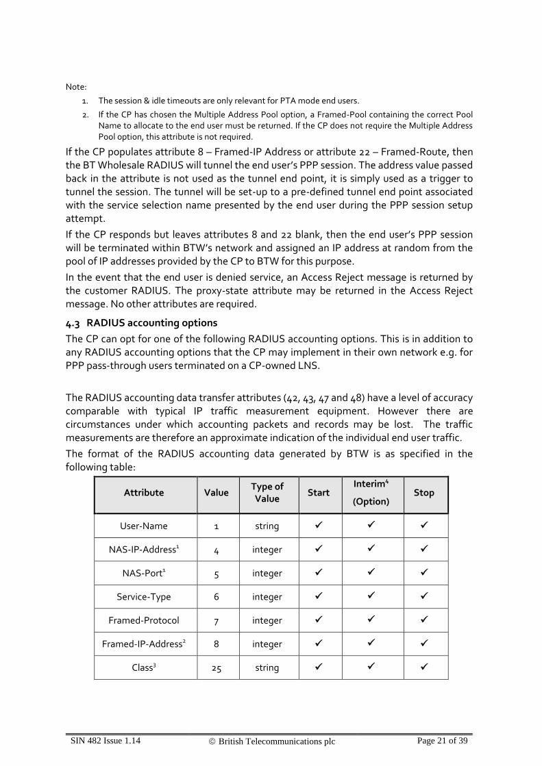
4.3 RADIUS accounting options
The CP can opt for one of the following RADIUS accounting options. This is in addition to any RADIUS accounting options that the CP may implement in their own network e.g. for PPP pass-through users terminated on a CP-owned LNS.
The RADIUS accounting data transfer attributes (42, 43, 47 and 48) have a level of accuracy comparable with typical IP traffic measurement equipment. However there are circumstances under which accounting packets and records may be lost. The traffic measurements are therefore an approximate indication of the individual end user traffic.
The format of the RADIUS accounting data generated by BTW is as specified in the following table:
Attribute Value Type of Value
Start Interim4
(Option) Stop
User-Name 1 string
NAS-IP-Address1 4 integer
NAS-Port1 5 integer
Service-Type 6 integer
Framed-Protocol 7 integer
Framed-IP-Address2 8 integer
Class3 25 string

SIN 482 Issue 1.14 British Telecommunications plc Page 22 of 39
Proxy-State 33 string
Acct-Status-Type 40 integer
Acct-Delay-Time 41 integer
Acct-Input-Octets 42 integer
Acct-Output-Octets 43 integer
Acct-Session-Id 44 string
Acct-Authentic 45 integer
Acct-Session-Time 46 integer
Acct-Input-Packets 47 integer
Acct-Output-Packets 48 integer
Acct-Terminate-Cause
49 integer
Acct-Input-Gigawords
52 integer
Acct-Output-Gigawords
53 integer
NAS-Port-Type 61 integer
Table 8 RADIUS Accounting Data Format
Notes:
1. NAS-IP-Address and NAS-Port are maintained but amended for security reasons.
2. Framed-IP-Address (Attribute 8) is only present in Accounting for PTA Mode End Users.
3. a) It is possible to have multiple Class attributes in accounting requests. b) Currently the IPstream Connect service does not support the presence of a null (hex 00) in the Class Attribute (attribute 25) string. If a null is used in attribute 25 in the access-accept, the string that appears in the accounting requests for the session may be truncated at the null.
4. The interim accounting period is two hours.
Accounting options:
- No BTW RADIUS accounting presented to the CP

SIN 482 Issue 1.14 British Telecommunications plc Page 23 of 39
The above accounting data is not presented to the CP
- Accounting with dual delivery or round robin
Where the dual delivery option is selected, data is sent to both separate CP server IP addresses. Where the Round robin option is selected and two CP server IP addresses are specified, BTW will send 2/3 of the accounting data to the first server IP address and 1/3 to the second. Where the Round robin option is selected and one CP server IP address is specified, BTW will send all accounting data to the server IP address. With either dual delivery or round robin options, the RADIUS accounting data is sent on a fire and forget basis.
- Accounting with geographic based delivery
For each BRAS location the CP can specify a server IP address, accounting data from that BRAS node is then presented to that server IP address. This option can be used in conjunction with the dual delivery or round robin option to deliver one accounting packet to an IP address based on BRAS location and a duplicate to an alternate IP address irrespective of BRAS location. With this option, the delivery of accounting data is on a fire and forget basis.
- SID into accounting
If this option is selected, the CP will be presented with the Service ID of the end user in attribute 31 (Calling-Station-Id) for each accounting packet. See SIN 497 for more details.
4.4 RADIUS setup and routing
The CP is responsible for ensuring that there is a route from the IPstream Connect network to the CP’s RADIUS. The CP has the option of advertising a route to the RADIUS through one or more of the interconnects to the IPstream Connect network using the BGP sessions established across the interconnect links between the CP’s and BTW’s routers. This is BTW’s preferred method of communication with the CP’s RADIUS servers. If the CP does not advertise the RADIUS address through any of the interconnects, then BTW will route the RADIUS traffic on to the internet in order to facilitate the connection - this should only be considered where the customer’s internet peering connectivity is trusted.
Note: For all routing methods to the CP’s RADIUS, the RADIUS addresses provided by the CP must be public registered RIPE addresses.
4.5 RADIUS standards
The Customer’s RADIUS Server must conditionally or unconditionally, comply with RFC 2865 “Remote Authentication Dial In User Service (RADIUS)”, 2866 “RADIUS Accounting”, 2867 “RADIUS Accounting Modifications for Tunnel Protocol Support”, 2868 “RADIUS Attributes for Tunnel Protocol Support” and 2869 “RADIUS Extensions” where applicable to the type of service required.

SIN 482 Issue 1.14 British Telecommunications plc Page 24 of 39
It should be noted that the value of the Response Authenticator field in Access-Accept, Access-Reject and Access-Challenge packets will be constructed in the form stated in RFC2865:
“ResponseAuth = MD5 (Code+ID+Length+RequestAuth+Attributes+Secret_ where + denotes concatenation”
RADIUS operation will consist of an Access-Request generated by the LAC or Home Gateway Router and forwarded the Customer’s RADIUS server. The Customer’s RADIUS Server must conditionally or unconditionally comply with the relevant RFC.
4.6 Presentation Domain (How the domain is presented to the Service Provider)
4.6.1 Format Options
This is how the username and domain name is presented to the Customer in the RADIUS Access requests. There are two formats available, listed below.
Default Domain Name
Two formats of presenting the domain name and user name are supported. These are:
Link.business-name.com/end.user
Please note:
The characters ‘!’, ‘/’, ‘\’, ‘%’‘@’ and ‘#’ are reserved characters and can not be used within a username or domain name.
It is possible for Customers to receive “domain/user” even if they are expecting “user@domain”. How this is processed is up to the Customer.
Please note that the Virtual Domain Name option (presented below) is not compatible with the ’/’ delimiter Domain Name format.
Virtual Domain Names
This option will allow a portion of the username to be included in the domain name of the IPstream Connect service.
For example, a Customer with a domain name of ‘sp.com’ (configured as a virtual domain), and a user with a username of Fred Smith who works for Acme will have [email protected] presented to their RADIUS. This could be used for example by groups of end users using multiple mailboxes from a single connection e.g. different first names for a family connection, employees of a company, or groups of end users who wish to retain their company identity when having service delivered by a 3rd party network provider.
With Virtual Domain Names everything to the left of the first ‘.’ in the Domain Name is treated as a wildcard, everything to the right of the first ‘.’ is treated as the selecting Domain Name (the Domain Name entered on the End User CRF). E.g. in:-
“fred” is the username

SIN 482 Issue 1.14 British Telecommunications plc Page 25 of 39
“bloggs” is the wildcard
“isp.com” is the selecting domain name.
Where a customer’s domain name is configured as a virtual domain name, BT’s network has been configured to accept an End User login with or without the ‘wildcard’ element of the virtual domain name. From the first example, both [email protected] and [email protected] would be valid. However, this functionality is dependent on an acceptable format for the selecting domain name.
Acceptable formats of the selecting domain name on the virtual domain order request are shown in the following examples.
Example 1. “isp.com”, “isp.net” etc, which allows end users to login with or without a wildcard preceding the selecting domain name (isp.com)
e.g. allowing logins of [email protected] OR [email protected] (where bloggs is a wildcard)
Example 2. “isp” where the end user of that customer will be using a wildcard [separated from the selecting domain name by a “.” (dot) ] to precede the selecting domain name as part of the end user login
e.g. allowing a login of [email protected] (where bloggs is the wildcard)
Please note that the login fred@isp will not work, where the selecting domain name is in the format “isp” i.e. with no ‘.’ (dot) in the selecting domain name.
4.6.2 Username and Domain Name length
The maximum length of the combined username and Domain Name string is 253 characters (including the separator).
The maximum length of a Domain Name is 32 characters (applies to everything to the right of the first ‘.’ if the Virtual Domain Name option is selected).
4.7 Test User Account
For testing purposes, BTW requires that CPs purchasing the IPstream Connect handover product provide a test end user account per service selection name configured. This should be of the format bt_test_user@service_selection_name, where service_selection_name is the CP’s normal service selection name. Please see section 5 for more details on test and diagnostic considerations for CPs purchasing IPStream Connect.
4.8 Session Handling under failure
If the BT IPstream Connect Service loses all connectivity with the Customer’s RADIUS server, then the BTW platform will mark the CP’s RADIUS server as “dead” and will not send any authentication requests to that server for 10 minutes. If all CP RADIUS servers are unavailable, then end users logging into service selection names that require CP RADIUS authentication will not be able to gain service.

SIN 482 Issue 1.14 British Telecommunications plc Page 26 of 39
4.9 PPPoE support and MTU size
The maximum MTU size on the BT Broadband network is 1500 bytes – the IPstream Connect infrastructure ensures that End User data packets up to and including this size are carried without fragmentation.
This applies at the layer being carried by IPstream PPP. If tunnelling protocols (such as PPTP or IPSEC) are being used over this connection then customers should advise end users to configure the MTU on these higher layers correspondingly smaller in order to ensure that the packets being carried by the IPstream PPP layer do not exceed 1500 bytes.
For PTA end users using PPPoE, the following steps occur within the end user authentication process:
PPPoE clients should behave as per RFC2516 and RFC1661 – if so:
PPPoE End User client should send an MRU of 1492 Bytes or less to the BTW BRAS.
The BTW BRAS will send an MRU of 1492 Bytes to the PPPoE client.
The PPPoE client and BTW BRAS will agree on the lower value MRU.
The BTW BRAS will advertise this as an IP MTU towards the Internet of 1492 Bytes (or lower if the client asked) for PPPoE End Users.
The BTW BRAS will continue to advertise 1500 Byte IP MTU for PPPoA End Users.
The DF bit on IP packets will be obeyed, not ignored or overwritten, so IP packets over 1492 Bytes to PPPoE End Users with the DF bit set will be dropped.
A message will be sent back to the server using ICMP stating the maximum packet size of 1492 Bytes.
If the PPPoE client does not obey RFC2516 and RFC1661 (which occurs regularly), one of two circumstances will occur:
If the PPPoE client does not send an MRU, but agrees the BTW BRAS MRU of 1492 Bytes, then the BTW BRAS will advertise this as the IP MTU for that End User to the Customer.
If the PPPoE client and BTW BRAS do not agree a valid MRU, then the BTW BRAS will default to advertising a value of 1500 Bytes as the IP MTU for that End User to the Customer.
If the End Users PC is behind the device raising the PPPoE session (for example on a routed LAN), then the IP MTU of the PC must be set to 1492 Bytes or lower.
For L2TP end users, the behaviour is the same with the addition that the BRAS will proxy on the MRU value to the LNS device in the CP’s network.

SIN 482 Issue 1.14 British Telecommunications plc Page 27 of 39
5. IPStream Connect diagnostic options
5.1 General
There are two areas that need additional consideration with regards to diagnosing end user problems when purchasing IPstream Connect.
5.2 xDSL IP test
The first area is the xDSL IP test. This test attempts to run a ping test between the end user’s router / modem and the PPP termination point within the network. Depending on the type of service that the CP has opted for the end user’s PPP session may terminate within the BT network at the BRAS (e.g. for PTA mode end users) or the session may be tunnelled into the CP’s network where it is terminated (LAC mode of operation for the BRAS).
The xDSL IP test forms part of the WOOSH one shot check. When instigated, the xDSL IP test will first query the BRAS to which the end user is connected to obtain details of the end user’s session. If the end user’s session is not up and running, the test ends here. Otherwise the test examines whether the PPP session terminates on the BRAS or not. If the session terminates on the BRAS, the xDSL IP test commands the BRAS to ping the IP address associated with the end user’s router / modem and the results are displayed for the CP via WOOSH.
LPA
BRAS
EUA
CPs network
DSLAM
ATM VP
Key:
End user traffic
carried as IP over PPP
sessionBTW OSS
Ping test
Figure 3. xDSL IP test for end user where PPP session is terminated on the BRAS

SIN 482 Issue 1.14 British Telecommunications plc Page 28 of 39
If the PPP session is tunnelled further into the network then the test logic ascertains the tunnel end point using information from the BRAS. At this point there is a check to see whether the CP has opted into end to end diagnostics for the xDSL IP test. If the CP has not, then the xDSL IP test goes no further. If the CP has opted into end to end diagnostics then BT’s OSS will attempt to communicate with the CP’s OSS via XML and in essence ask the CP’s OSS for results for a ping test from the tunnel end point to the end user in question. This information is then presented back in the results of the xDSL IP test (e.g. as part of the WOOSH one shot check).
LPA
BRAS
EUA
CPs network
LNSDSLAM
ATM VP
Key:
End user traffic
carried as IP over PPP
session
BTW OSS CPs OSS
Ping test
Figure 4. xDSL IP test for L2TP end users, where CP has opted into end to end diagnostics
5.3 Performance tester
The performance tester is used to help identify situations where there is a slow speed fault within the network by downloading a file across the end user’s connection from the performance tester web server (accessed by typing http://test.speedtester.bt.com into a web browser running on the end user’s PC). The performance tester web pages guide the end user through the tests as detailed in the performance tester handbook.
When the end user initially visits the performance tester webpage some validation of the end user is carried out using their telephone number and username.
SIN 482 Issue 1.14 British Telecommunications plc Page 29 of 39
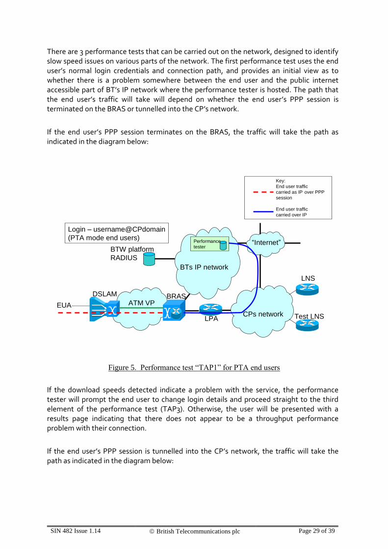
There are 3 performance tests that can be carried out on the network, designed to identify slow speed issues on various parts of the network. The first performance test uses the end user’s normal login credentials and connection path, and provides an initial view as to whether there is a problem somewhere between the end user and the public internet accessible part of BT’s IP network where the performance tester is hosted. The path that the end user’s traffic will take will depend on whether the end user’s PPP session is terminated on the BRAS or tunnelled into the CP’s network.
If the end user’s PPP session terminates on the BRAS, the traffic will take the path as indicated in the diagram below:
LPA
BRAS
EUA
Performance
tester
CPs network
LNS
Test LNS
BTW platform
RADIUS
“Internet”
BTs IP network
DSLAM
ATM VP
Login – username@CPdomain
(PTA mode end users)
Key:
End user traffic
carried as IP over PPP
session
End user traffic
carried over IP
Figure 5. Performance test “TAP1” for PTA end users
If the download speeds detected indicate a problem with the service, the performance tester will prompt the end user to change login details and proceed straight to the third element of the performance test (TAP3). Otherwise, the user will be presented with a results page indicating that there does not appear to be a throughput performance problem with their connection.
If the end user’s PPP session is tunnelled into the CP’s network, the traffic will take the path as indicated in the diagram below:

SIN 482 Issue 1.14 British Telecommunications plc Page 30 of 39
LPA
BRAS
EUA
Performance
tester
CPs network
LNS
Test LNS
BTW platform
RADIUS
“Internet”
BTs IP network
DSLAM
ATM VP
Login – username@CPdomain
(L2TP end users)
Key:
End user traffic
carried as IP over PPP
session
End user traffic
carried over IP
Figure 6. Performance test “TAP1” for L2TP end users
If the download speeds detected indicate a problem with the service, the performance tester will prompt the end user to change login details and proceed to the second element of the performance test (TAP2). Otherwise, the user will be presented with a results page indicating that there does not appear to be a throughput performance problem with their connection.
For the second performance test (which does not apply to end users whose PPP session normally terminates on the BRAS) the end user is asked to login as bt_test_user@<cpdomain>, where <cpdomain> is their normal login domain / realm / SSN. As far as the BT platform is concerned, the BT platform RADIUS only inspects the SSN when determining tunnel end points, so when the end user attempts to login as bt_test_user@cpdomain, the RADIUS will instruct the BRAS to tunnel the end user’s PPP session as if the end user had logged in using their normal username. It is up to the CP to determine whether to terminate the end user on a different part of their network if it detects the end user has logged in with the bt_test_user username.

SIN 482 Issue 1.14 British Telecommunications plc Page 31 of 39
It should be understood that the webpage will direct the end user to type these details into their router / modem, so it is strongly advised that the CP should at least terminate a PPP session logging in with these details, even if the session is terminated in the same way as the user’s normal login credentials. This will allow TAP2 to run and proceed to TAP3 to test the access network. However, CPs can gain most benefit from this second test if they can terminate the end user session in a way that allows a more reliable, less congested path to the performance tester. Comparing the test results from TAP1 and TAP2 in this manner allows a CP to understand where a potential problem may lie within its own network.
LPA
BRAS
EUA
Performance
tester
CPs network
LNS
Test LNS
BTW platform
RADIUS
“Internet”
BTs IP network
DSLAM
ATM VP
Login – bt_test_user@CPdomain
Key:
End user traffic
carried as IP over PPP
session
End user traffic
carried over IP
Figure 7. Performance test “TAP2”, connecting to optional test LNS within the CP’s network
Once the end user has connected using the new login credentials a file download is carried out and throughput to the end user ascertained. If the outcome of TAP2 indicates a performance problem then the test sequence proceeds to TAP3.
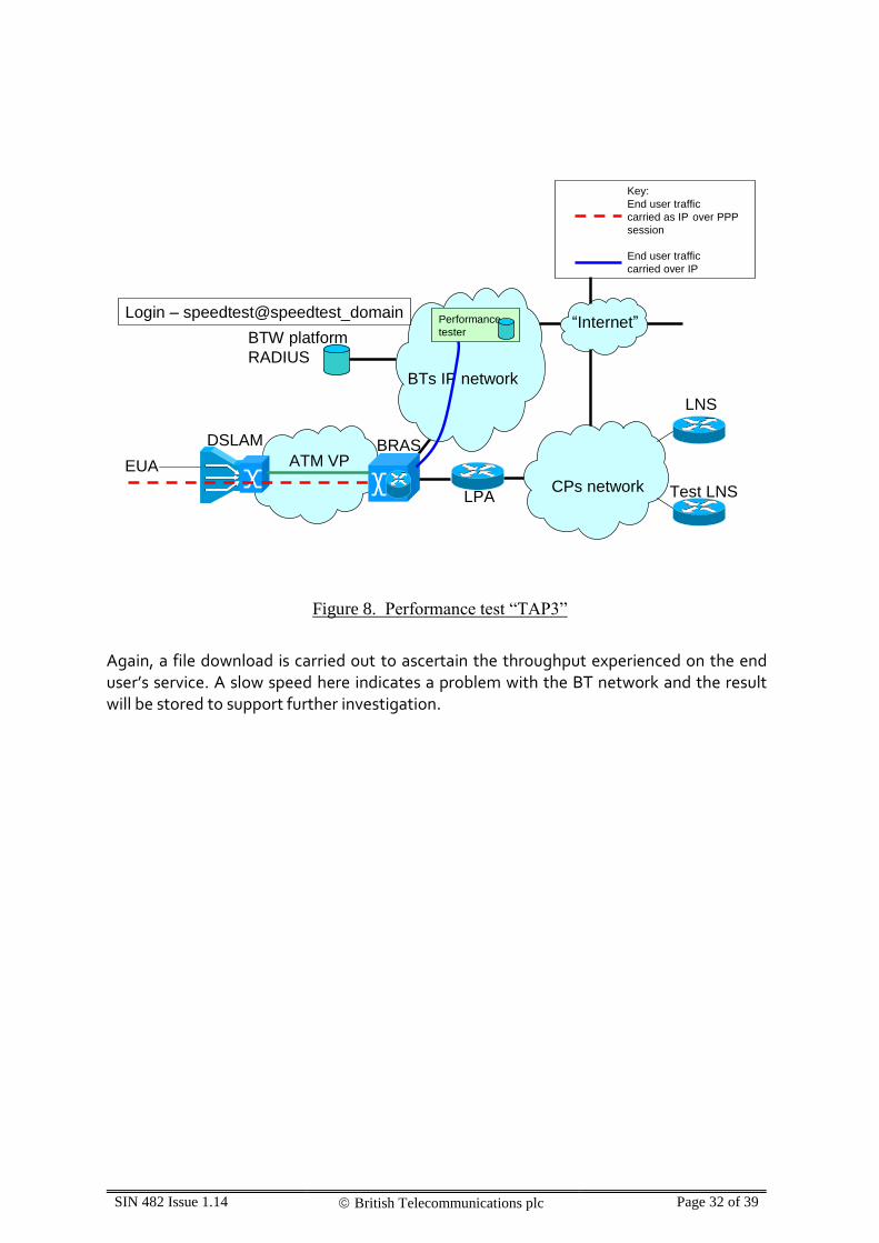
For performance test TAP3, the end user is asked to re-configure their router modem to login as speedtest@speedtest_domain. This prompts the BT network to terminate the session on one of a specific pool of IP addresses at the BRAS. The user has limited access from these IP addresses but from one of these IP addresses the user can access the performance tester from within BT’s network without traffic being routed over the connectivity to the CP’s network. This is illustrated in the diagram below:
SIN 482 Issue 1.14 British Telecommunications plc Page 32 of 39
LPA
BRAS
EUA
CPs network
LNS
Test LNS
BTW platform
RADIUS
“Internet”
BTs IP network
DSLAM
ATM VP
Performance
tester
Login – speedtest@speedtest_domain
Key:
End user traffic
carried as IP over PPP
session
End user traffic
carried over IP
Figure 8. Performance test “TAP3”
Again, a file download is carried out to ascertain the throughput experienced on the end user’s service. A slow speed here indicates a problem with the BT network and the result will be stored to support further investigation.

SIN 482 Issue 1.14 British Telecommunications plc Page 33 of 39
6. References
[1] SIN 302 BT Internet Protocol Transport Services, Service Description
[2] SIN 485 BT IPstream Connect Office & BT IPstream Connect Home Products, Service Description and Interface Specification
[3] SIN 487 BT IPstream Connect Symmetric, Service Description and Interface Specification
[4] RFC2364 PPP Over AAL5
[5] RFC2516 A Method for Transmitting PPP Over Ethernet (PPPoE)
[6] RFC1661 The Point-to-Point Protocol (PPP)
[7] Ethernet MSIL Product Handbooks
[9] SIN 496 BT IPstream Connect SID for Authentication
[10] SIN 497 BT IPstream Connect SID for Accounting
[11] [Removed]
[12] SIN 502 BT IPstream Connect Session Steering
SINs are available at http://www.btplc.com/sinet/
BT Wholesale Ethernet MSIL Documentation is available at http://www.btwholesale.com/pages/static/Products/Interconnect/MSIL_Ethernet.html
For copies of other referenced documents, please see the contacts on the Document Sources page at http://www.btplc.com/sinet/
7. Abbreviations
AAL ATM Adaptation Layer
ABC Alarms By Carrier
AC Alternating Current
ADSL Asymmetric Digital Subscriber Line
AS Autonomous System
ASN Autonomous System Number
ATM Asynchronous Transfer Mode
BAS Broadband Access Server
BC Business Customer
BGP Border Gateway Protocol

SIN 482 Issue 1.14 British Telecommunications plc Page 34 of 39
BRAS Broadband Remote Access Server
BTW BT Wholesale
C+ BT Central Plus
CD Compact Disc
CDC Communication Device Class
CHAP Challenge Handshake Authentication Protocol
CRF Customer Requirements Form
DHCP Dynamic Host Configuration Protocol
DNS Domain Name System/Server
EGP Exterior Gateway Protocol
EU End User
HEC Header Error Check
HG Home Gateway
HGR Home Gateway Router
IEEE Institute of Electronic and Electrical Engineers
IETF Internet Engineering Task Force
IGP Interior Gateway Protocol
IP Internet Protocol
IPR Intellectual Property Rights
ISDN Integrated Services Digital Network
ISP Internet Service Provider
L2TP Layer 2 Tunnelling Protocol
LAC L2TP Access Concentrator (function in BAS)
LAG Line Aggregation Group
LAN Local Area Network
LNS L2TP Network Server (e.g. Home Gateway)
(L2TP) Layer 2 Tunnelling Protocol
LTS Layer 2 Tunnelling Protocol Tunnel Switch
kbit/s Kilobits per second
Mbit/s Megabits per second
MHz Mega-Hertz
MSIL Multi Service Interconnect Link
NAT Network Address Translation
no NAT Optional removal of NAT for Static IP Addressing
NTE Network Termination Equipment
OSPF Open Shortest Path First protocol
SIN 482 Issue 1.14 British Telecommunications plc Page 35 of 39
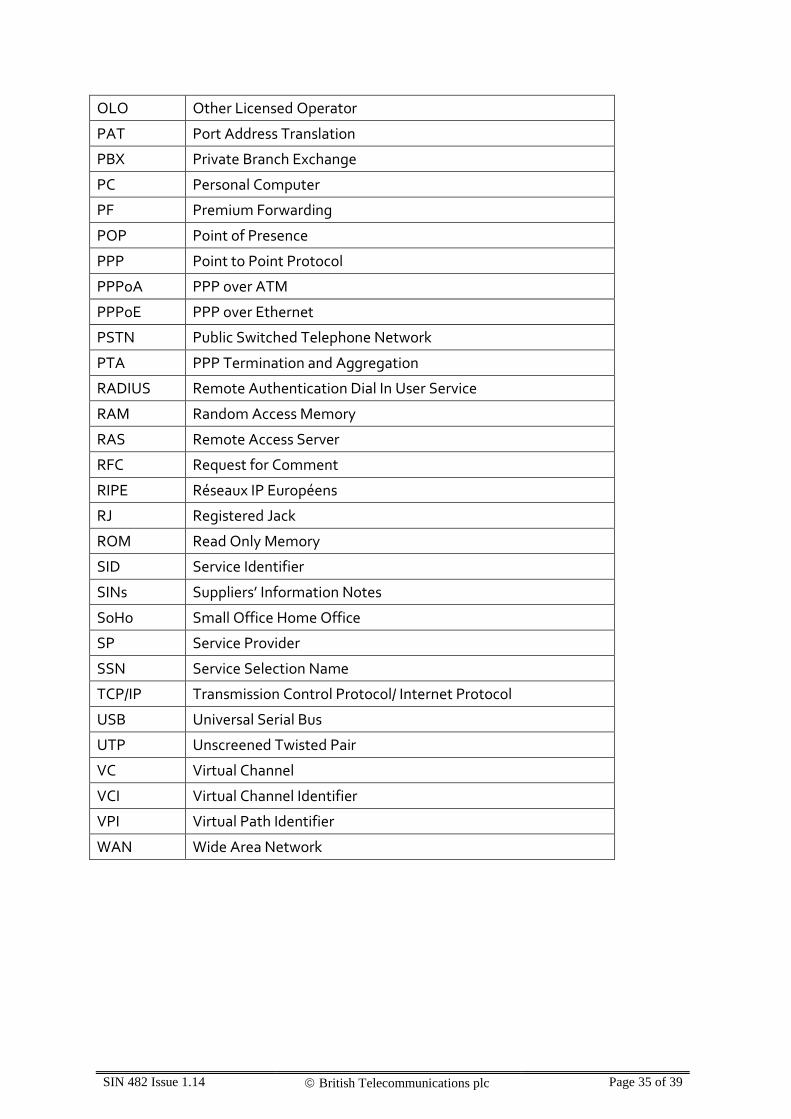
OLO Other Licensed Operator
PAT Port Address Translation
PBX Private Branch Exchange
PC Personal Computer
PF Premium Forwarding
POP Point of Presence
PPP Point to Point Protocol
PPPoA PPP over ATM
PPPoE PPP over Ethernet
PSTN Public Switched Telephone Network
PTA PPP Termination and Aggregation
RADIUS Remote Authentication Dial In User Service
RAM Random Access Memory
RAS Remote Access Server
RFC Request for Comment
RIPE Réseaux IP Européens
RJ Registered Jack
ROM Read Only Memory
SID Service Identifier
SINs Suppliers’ Information Notes
SoHo Small Office Home Office
SP Service Provider
SSN Service Selection Name
TCP/IP Transmission Control Protocol/ Internet Protocol
USB Universal Serial Bus
UTP Unscreened Twisted Pair
VC Virtual Channel
VCI Virtual Channel Identifier
VPI Virtual Path Identifier
WAN Wide Area Network

SIN 482 Issue 1.14 British Telecommunications plc Page 36 of 39
8. History
Date Issue Comment
12 March 2008 1.0 First Issue
1 May 2008 1.1 Amended and clarified references to MSIL documentation
19 June 2008 1.2 Amended to incorporate references to new IPStream Connect SINs 485 & 487. Also minor corrections have been made under Routing Protocols (Section 3.3.4) and Geographic-based delivery (Section 4.3).
19 November 2008 1.3 Added new section "IPstream Connect Diagnostic Options". This provides clarity on existing test & diagnostic considerations, and does not introduce any new features..
19 December 2008 1.4 Correction to wording section 3.3.2. Removed aggregated billing, and replaced with node billing.
September 2009 1.5 Modifications to the following sections:
1. Changes to SIN references and wording
3.3.2 Clarification to commercial arrangements
3.3.3 Clarification on use of MSIL
3.3.4 Clarification to routing protocols,
4.1 Clarification of L2TP & PTA service
4.2.4 Clarification of L2TP authentication
4.3 Clarification of Accounting attributes
4.4 Clarification of RADIUS IP address type
General – minor wording changes
November 2009 1.6 3.3.3 - Modified to highlight handover link limit – 8 pairs of links per node maximum and all links at a node must be the same size. Also clarified 21C handover option.
3.3.4 – Clarification on load-balancing for PTA mode
4.2.2 & 4.2.4 – Modified to reflect that the proxy-state attribute may be included in the access reject.
General – minor wording changes
March 2010 1.7 3.3 – Minor changes to section numbers

SIN 482 Issue 1.14 British Telecommunications plc Page 37 of 39
3.3.6 - Clarified the use of L2TP control packets
3.3.7 - Added Link Tagging option
September 2010 1.8 1. – Wording change for the Symmetric service
3.3.4 – Clarified the number of CP RADIUS servers supported for Authentication & Accounting
4.2.4 – Clarified that the timeouts are relevant for PTA customers only
4.6.1 – Removed Domain Name-less option as no longer supported. Made a wording change.
3.3.4, 4.1, 4.2.2 & 4.2.4 – Introduced description of PTA Multiple Address Pools functionality.
October 2010 1.9 1., 3.3.4, 5.2, 5.3 & Appendix A - Included the introduction of Content Connect
November 2010 1.10 1. & Appendix A - Minor wording changes
4.1 – Clarified two current PTA Multiple Address Pool restrictions
May 2011 1.11 1., 4.2 & 6. – Introduced L2TP Session Steering option and referenced SIN 502
4.2 – Clarified the Authentication options
1., 6. & Appendix A - Updated reference from STIN 504 to SIN 504
January 2012 1.12 Section 1, Appendix A – Removed references to Content Connect Basic; removed references to SIN 504 and introduced reference to CDN Integration and User Guide;
Appendix A – Minor change to wording for handling of IP Address Ranges & Content Connect charging
April 2013 1.13 Section 1., 4.2.2 & Appendix A – Removed references to Advanced Services
December 2015 1.14 Section 1, 3.3.4, 5.2, 5.3, 6 and 7. – Changes to reflect the withdrawal of Content Connect
Appendix A – Content Connect Appendix removed
Change SINet site references from http://www.sinet.bt.com to

SIN 482 Issue 1.14 British Telecommunications plc Page 38 of 39
http://www.btplc.com/sinet/

SIN 482 Issue 1.14 British Telecommunications plc Page 39 of 39