simulation, optimization and design of 3d printed sand ... of the future/3d printing... ·...
TRANSCRIPT
VTT TECHNICAL RESEARCH CENTRE OF FINLAND LTD
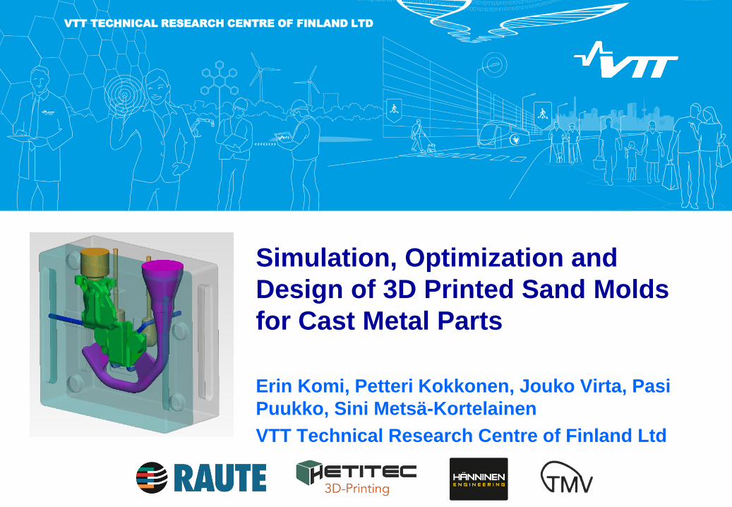
Simulation, Optimization and
Design of 3D Printed Sand Molds
for Cast Metal Parts
Erin Komi, Petteri Kokkonen, Jouko Virta, Pasi
Puukko, Sini Metsä-Kortelainen
VTT Technical Research Centre of Finland Ltd
26/11/2016 2
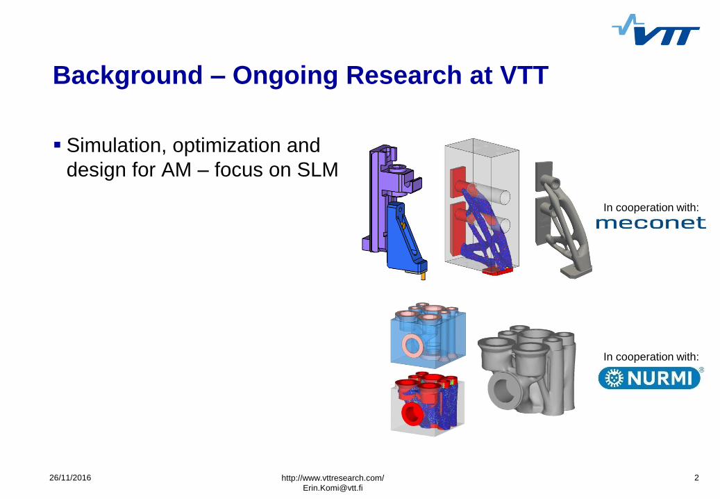
Background – Ongoing Research at VTT
Simulation, optimization and
design for AM – focus on SLM
http://www.vttresearch.com/
In cooperation with:
In cooperation with:
26/11/2016 3
In cooperation with:
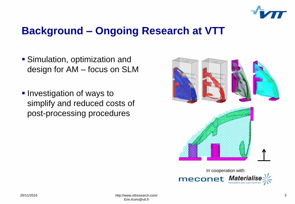
Background – Ongoing Research at VTT
Simulation, optimization and
design for AM – focus on SLM
Investigation of ways to
simplify and reduced costs of
post-processing procedures
http://www.vttresearch.com/
26/11/2016 4
In cooperation with:
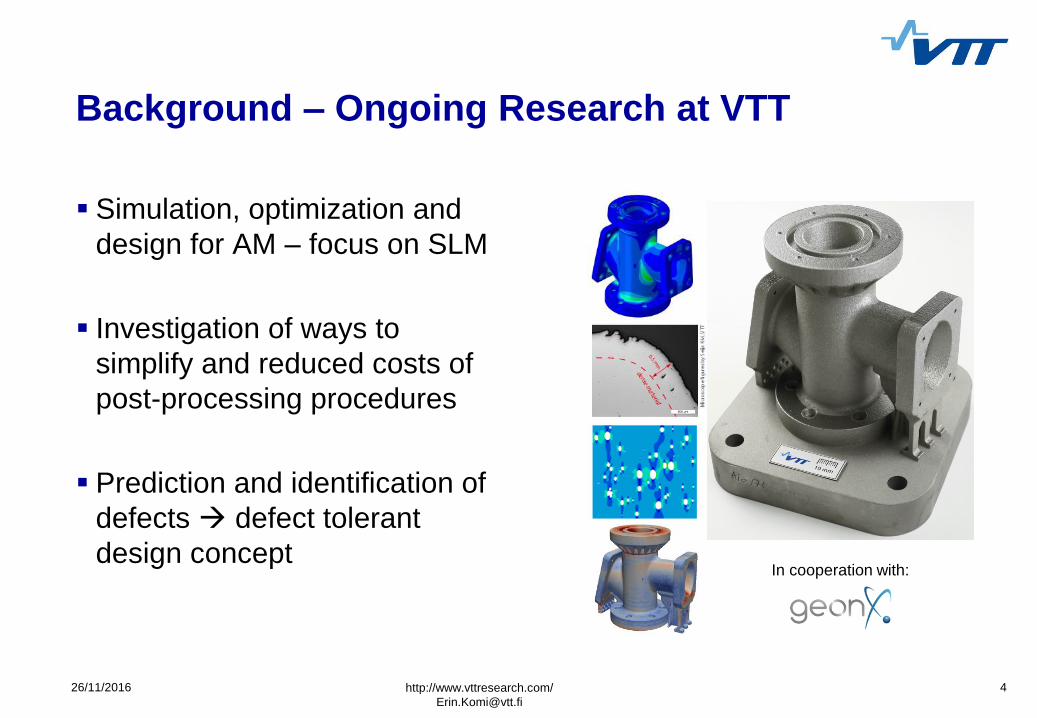
Background – Ongoing Research at VTT
Simulation, optimization and
design for AM – focus on SLM
Investigation of ways to
simplify and reduced costs of
post-processing procedures
Prediction and identification of
defects defect tolerant
design concept
http://www.vttresearch.com/
26/11/2016 5
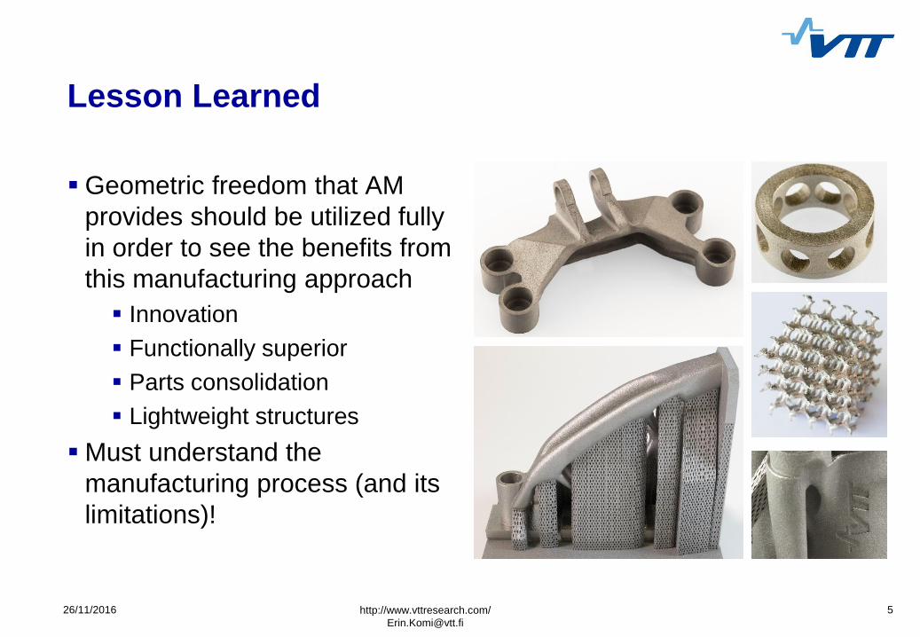
Lesson Learned
Geometric freedom that AM
provides should be utilized fully
in order to see the benefits from
this manufacturing approach
Innovation
Functionally superior
Parts consolidation
Lightweight structures
Must understand the
manufacturing process (and its
limitations)!
http://www.vttresearch.com/
6 26/11/2016
Current Project
MOTIVATION
Some key limitations in metal
AM:
Size
Material selection
Quality assurance
Cost
Typical ‘large’ powder bed
fusion build sizes:
400 x 400 x 400 mm³ (EOS)
500 x 280 x 365 mm³ (SLM)
PROPOSED SOLUTION
3D printed sand molds for cast
metal components keep
much of geometric freedom
Largest cohesive build space for
sand molds 4m x 2m x 1m
(Voxeljet)
Process is suitable for most
metals that can be cast with
sand casting method (e.g.
magnesium, aluminum, steel,
brass, etc.)
http://www.vttresearch.com/
26/11/2016 7
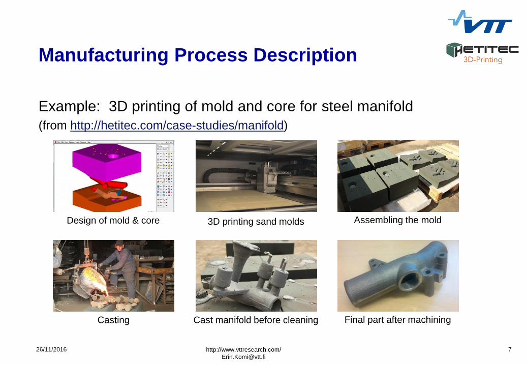
Manufacturing Process Description
Example: 3D printing of mold and core for steel manifold
(from http://hetitec.com/case-studies/manifold)
http://www.vttresearch.com/
Design of mold & core 3D printing sand molds Assembling the mold
Casting Cast manifold before cleaning Final part after machining
8 26/11/2016
Primary Manufacturing Constraints
3D printing of the sand mold
A wall thickness of 3mm must
be maintained in the sand
mold
It must be possible to remove
excess sand Mold must
have parting line
Casting
A minimum wall thickness of
e.g. 5mm is recommended
(varies with material)
Long, thin channels are
challenging (need long, thin,
and fragile cores)
http://www.vttresearch.com/
26/11/2016 9
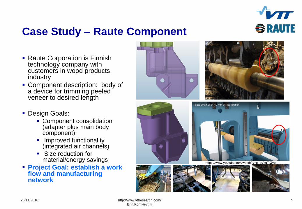
Case Study – Raute Component
Raute Corporation is Finnish technology company with customers in wood products industry
Component description: body of a device for trimming peeled veneer to desired length
Design Goals: Component consolidation
(adapter plus main body component)
Improved functionality (integrated air channels)
Size reduction for material/energy savings
Project Goal: establish a work flow and manufacturing network
http://www.vttresearch.com/
26/11/2016 10
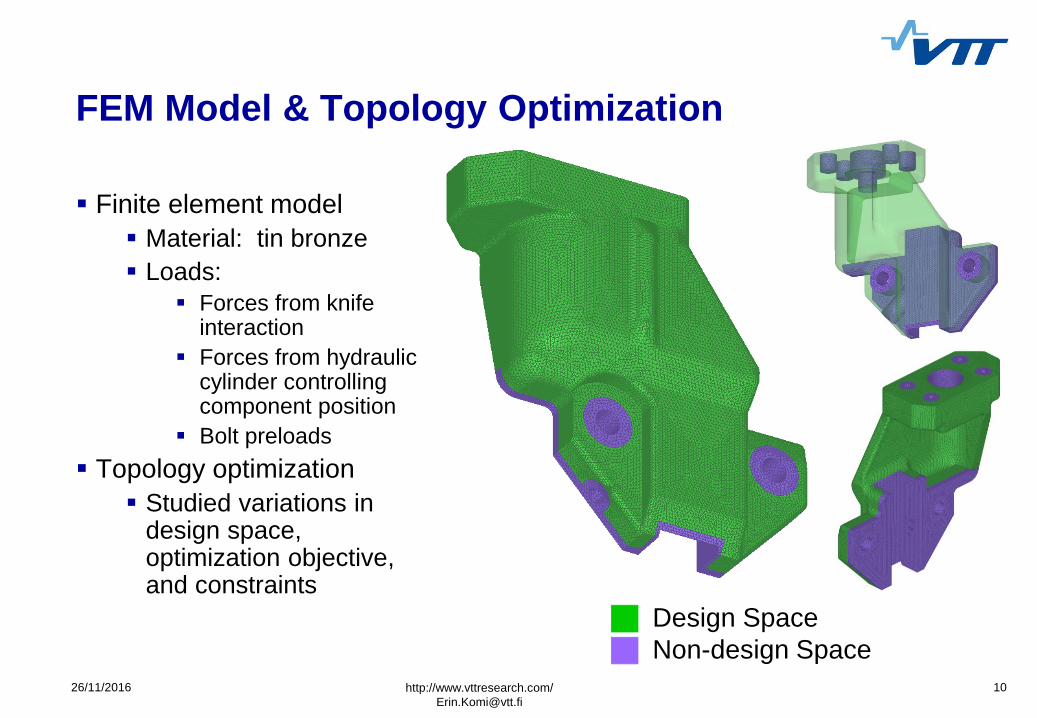
FEM Model & Topology Optimization
Finite element model
Material: tin bronze
Loads:
Forces from knife interaction
Forces from hydraulic cylinder controlling component position
Bolt preloads
Topology optimization
Studied variations in design space, optimization objective, and constraints
http://www.vttresearch.com/
Design Space
Non-design Space
26/11/2016 12
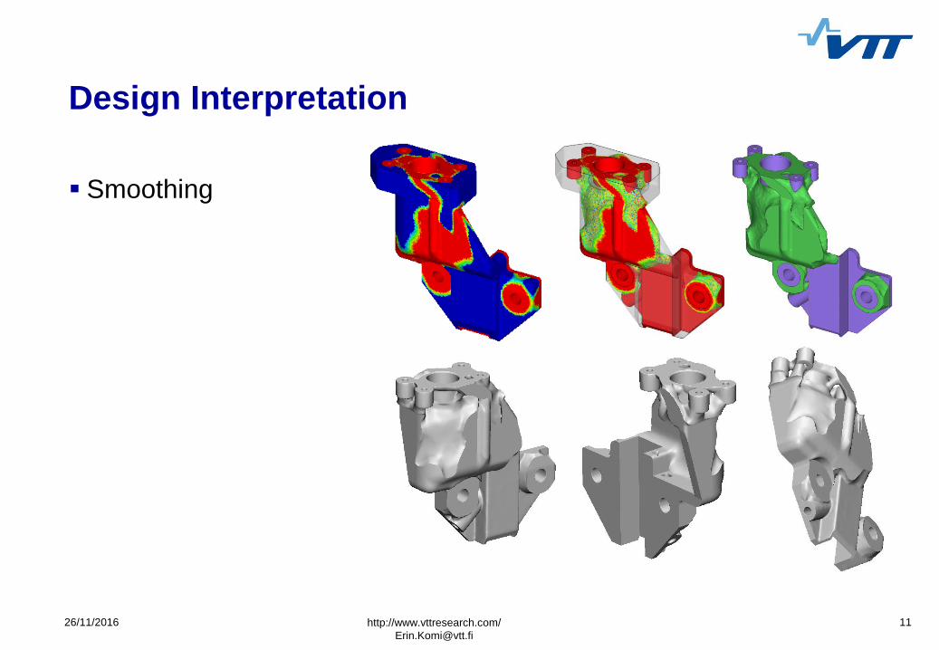
Design Interpretation
Smoothing
Manufacturability check
http://www.vttresearch.com/
26/11/2016 13
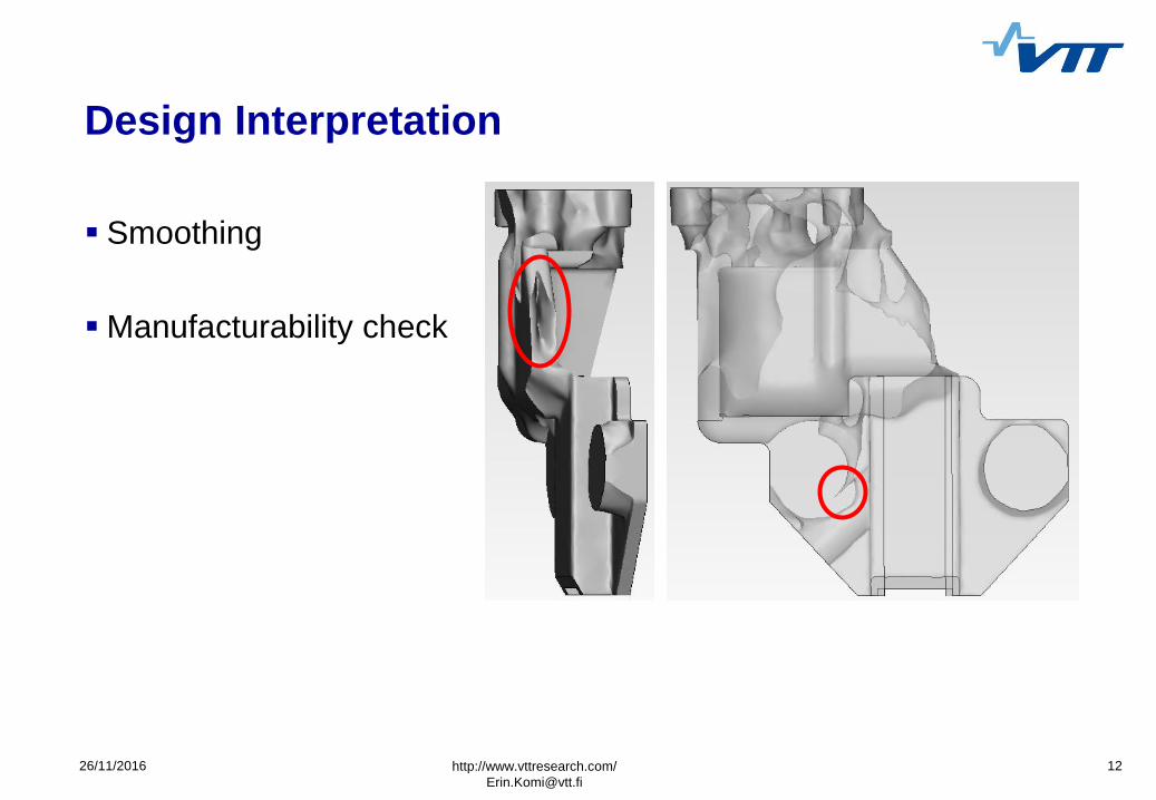
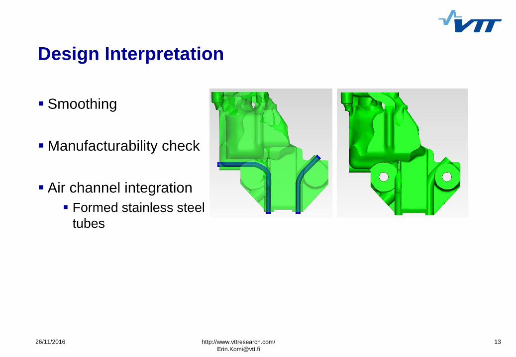
Design Interpretation
Smoothing
Manufacturability check
Air channel integration
Formed stainless steel
tubes
http://www.vttresearch.com/
26/11/2016 14
Casting Simulation & Mold Design (1/3)
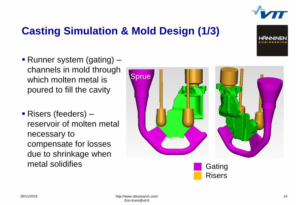
Runner system (gating) –
channels in mold through
which molten metal is
poured to fill the cavity
Risers (feeders) –
reservoir of molten metal
necessary to
compensate for losses
due to shrinkage when
metal solidifies
http://www.vttresearch.com/
Gating
Risers
Sprue
26/11/2016 15
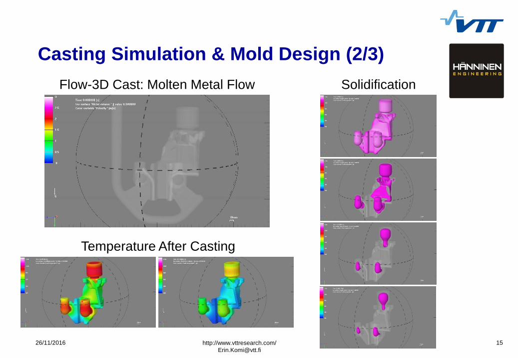
Casting Simulation & Mold Design (2/3)
http://www.vttresearch.com/
Solidification Flow-3D Cast: Molten Metal Flow
Temperature After Casting
26/11/2016 16
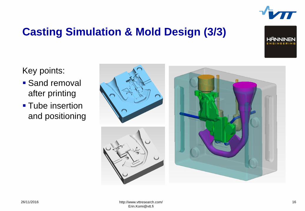
Casting Simulation & Mold Design (3/3)
Key points:
Sand removal
after printing
Tube insertion
and positioning
http://www.vttresearch.com/
26/11/2016 17
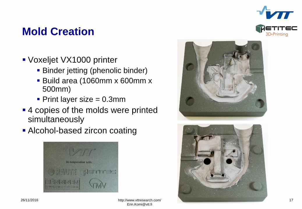
Mold Creation
Voxeljet VX1000 printer
Binder jetting (phenolic binder)
Build area (1060mm x 600mm x 500mm)
Print layer size = 0.3mm
4 copies of the molds were printed simultaneously
Alcohol-based zircon coating
http://www.vttresearch.com/
26/11/2016 18
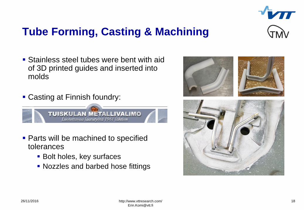
Tube Forming, Casting & Machining
Stainless steel tubes were bent with aid of 3D printed guides and inserted into molds
Casting at Finnish foundry:
Parts will be machined to specified tolerances
Bolt holes, key surfaces
Nozzles and barbed hose fittings
http://www.vttresearch.com/
26/11/2016 19
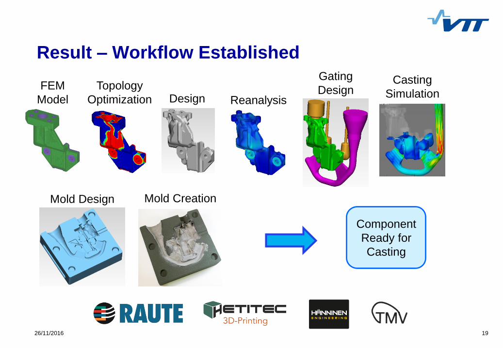
Result – Workflow Established
FEM
Model
Topology
Optimization Design Reanalysis
Gating
Design Casting
Simulation
Mold Design
Component
Ready for
Casting
Mold Creation
26/11/2016 20
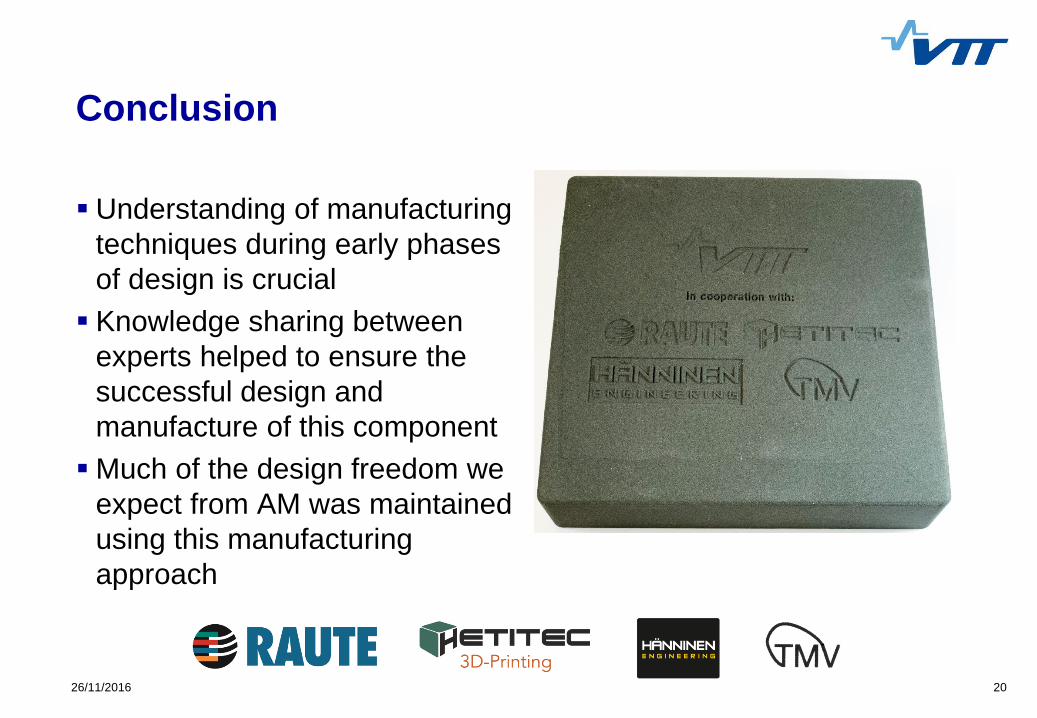
Conclusion
Understanding of manufacturing
techniques during early phases
of design is crucial
Knowledge sharing between
experts helped to ensure the
successful design and
manufacture of this component
Much of the design freedom we
expect from AM was maintained
using this manufacturing
approach

TECHNOLOGY FOR BUSINESS