simulation of time-of-flight sensors using global illumination
TRANSCRIPT

Vision, Modeling, and Visualization (2013)Michael Bronstein, Jean Favre, and Kai Hormann (Eds.)
Simulation of Time-of-Flight Sensors using Global
Illumination
S. Meister1 and R. Nair1 and D. Kondermann1
1Heidelberg Collaboratory for Image Processing, University of Heidelberg, Germany
Abstract
Time-of-Flight (ToF) cameras use specialized sensors and modulated infrared light to simultaneously obtain depth,
amplitude and intensity images. Depth images from such cameras suffer from various errors which exhibit a more
complex behavior than traditional intensity images. Of these errors, the phenomenon of multi-reflection or multi-
path interference poses the biggest challenge to researchers. It is caused by indirect light paths between camera
and light source and is therefore dependent on scene geometry. While simulated data can be used for ground truth
evaluation and whitebox testing, current simulators do not model multipath effects. The method we present is capa-
ble of simulating all scene-dependant effects by taking global illumination into consideration. This is accomplished
by modifying a bidirectional path tracing algorithm such that it takes the time-dependent propagation of modulated
light in a scene into consideration. Furthermore, by combination of the proposed method with a previous hardware
simulator we are capable of reproducing all effects in ToF cameras. The system was validated both on test targets
with known real Time of Flight camera responses as well as qualitatively on a more complex room scene. The simu-
lator as well as the source code is available at http://hci.iwr.uni-heidelberg.de/Benchmarks/.
Categories and Subject Descriptors (according to ACM CCS): I.3.3 [Computer Graphics]: Picture/ImageGeneration—
1. Introduction
Time of Flight (ToF) imaging is a depth acquisition modal-ity with many interesting properties such as independent, perpixel depth measurements, well localized object contoursand robustness towards ambient light. It is interesting forvarious applications ranging from 3D-reconstruction overHCI to driver assistance systems. However, depth maps ob-tained with these cameras show a variety of systematic andstatistical errors such as depth noise, flying pixels or multi-path interference. Therefore, the development of methods tocompensate for these effects is an active field of research.
Validation and benchmarking of such algorithms is a chal-lenging task. Ground truth comparisons are usually limitedto images taken in controlled lab conditions, as only heresufficiently correct ground truth can be acquired. Recent re-search by Wulff et al. [WBSB12] or Meister et al. [MK11]suggest that computer generated images are in many casessuitable alternatives for algorithm validation. Unlike mea-sured ground truth where the challenges lie in the measure-ment accuracy and reference data alignment, simulation re-quires all observable effects to be modeled properly by the
Figure 1: Processing Pipeline of our algorithm: Starting
from a scene description path tracing based global illumi-
nation is used to generate four raw phase frames. The scene
depth can then be recomputed from these phase images.
system. For ToF imaging, none of the current methods arecapable of simulating all ToF related errors simultaneously.
c© The Eurographics Association 2013.
DOI: 10.2312/PE.VMV.VMV13.033-040

S. Meister & R. Nair & D. Kondermann / Simulation of Time-of-Flight Sensors using Global Illumination
The method we present here is capable of simulating allscene dependent effects in ToF data including multipath ef-fects caused by global lighting. To accomplish this, we bor-row from methods known in the computer graphics commu-nity to correctly simulate light propagation.
There, global illumination algorithms are used to simulateboth direct and indirect light as well as material propertieslike reflection, transmission and scattering. However, thesemethods assume that light propagation is instantaneous andeach frame is in a steady state. Our method extends a pathtracing global illumination method to also consider the finitespeed of light. A rundown of the pipeline is given in Fig.1.
We will focus on the simulation of multipath interferenceas well as artifacts caused by indirect illumination, as theyhave not been addressed in literature yet. The rest of thispaper is organized as follows. After giving a brief overviewof related work in Section 2, we will give an introductionto ToF imaging and error sources in Section 3. We will thenintroduce our simulator in Section 4 and discuss evaluationexperiments in Section 5.
2. Related Work
Multiple methods for the classification, measurement and re-moval of errors inherent in time-of-flight images have beendescribed, for example by Plaue [Pla06], Schmidt [Sch08],Lindner and Kolb [LK07] or Falie and Buzuloiu [FB08].
The estimation and compensation of multipath interfer-ence in time-of-flight cameras has been the focus of recentinvestigation e.g. by Fuchs [Fuc10], Jiménez et al [JPMP12]or Dorrington et al. [DGC∗11]. Most of the described meth-ods assume that the involved materials have lambertian re-flectance properties or take only simple one-time reflectionsinto consideration. Scattering inside the camera casing andlens is related to this problem and has been investigated byKarel et al. [KGP12].
A method for simulating the sensor of time-of-flight cam-eras has been described by Schmidt [Sch11].
In contrast we simulate the light propagation in a scene.In computer graphics Smith et al. [SSD07] were the firstto postulate a generic time-dependent form of the render-ing equation. Regarding time-of-flight cameras, this has onlybeen performed by Keller, Kolb et al. [KOKP07] [KK09]. Intheir work they presented an extensive framework for time-of-flight simulation based on scanline-rendering.
Our proposed method enhances previous methods by sim-ulating multipath interference via path tracing. The usageof Monte Carlo methods to simulate multiple light scatter-ings is not new as it has already been employed for theevaluation of LiDAR systems. Examples are the works ofGordon [Gor82] describing the effect of laser reflections onoceanic surfaces or the works by Kunkel et al. [KW76] whoinvestigated multiple atmospheric scatterings.
Figure 2: Raw phase images of synthetic Kitchen scene (col-
orcoded logarithm). Well visible are the intensity changes at
different depths. Reflecting surfaces such as the chrome on
the oven door appear very dark as they reflect only indirectly
illuminated surfaces.
In the following two sections, we will summarize theworking principles of time-of-flight cameras as well as thebidirectional path tracing algorithm and our modifications toit.
3. Time-of-Flight Cameras
Continuous-wave time-of-flight depth cameras use a varia-tion of the following principle: the intensity of an active lightsource (LEDs mounted coaxial to the camera optic) is mod-ulated with a Megahertz-range frequency. The image sensorcorrelates the input signal created by the reflected light withthe modulation reference signal to calculate the phase shiftφ. This phase-shift is proportional to the traveled light dis-tance modulo the ambiguity range (7.5m for a modulationfrequency of 20 MHz) due to the periodicity of the modula-tion signal. Some laser range finders use a similar principlealthough a time-of-flight camera can perform the depth cal-culation for a whole image simultaneously.
At least 4 raw frames (I0−3) measured at four differentphases are necessary to compute the depth. An example for asynthetic Kitchen scene can be seen in Figure 2 (see section5 for details).
For phase shifts λ of 12 π, π and 3
2 π, a modulation fre-quency f and light speed c the distance d of an object tothe camera can be computed as:
d ∝ atan
(
I3 − I1
I0 − I2
)
·
c
f
Different sensor models may capture more raw frames tocompensate for noise or background illumination. More de-tails on the CamCube sensor and a detailed error analysiscan be found in [Pla06] or [Sch08].
c© The Eurographics Association 2013.
34

S. Meister & R. Nair & D. Kondermann / Simulation of Time-of-Flight Sensors using Global Illumination
Figure 3: Principle of Bidirectional Path Tracing: eye paths
are blue, light path are red. At each intersection point the
paths are connected (green lines). Also the algorithm tries to
connect eye path intersections directly with the light sources
(gray path, here invalid due to shadowing).
There are multiple sources of errors which cause the re-sult of this equation to differ from the true object-to-cameradistance. Apart from different random noise sources (elec-tronics, photon noise, etc.) the most prevalent error is mul-tipath or interreflection. It results in flying pixels at objectcorners or overestimated depths. Multipath error is causedby light which did not travel a direct path from the light intothe scene and back to the camera but was reflected multipletimes. In a computer graphics context such effects could besummarized as global illumination. Due to these errors thesensor reports a depth value which is typically higher thanthe true depth as well as dependent on intensity. Additionalerrors e.g. the wiggling error, which arise from the fact thatthe modulation signal is not perfectly sinusoidal can be re-moved by calibration. See the works by Rapp [RFHJ08] orErz and Jähne [EJ09].
4. Phase Modulated Bidirectional Path Tracing
Bidirectional Path Tracing as introduced by Lafortune andWillems [LW93] and Veach and Guibas [VG95] solvesthe global illumination problem of the rendering equation,which was first described in detail by Immel et al. [ICG86]and Kajiya [Kaj86]. It synthesizes an image in the follow-ing way: A view ray from the camera is sampled and tracedinto the scene. Once it intersects a polygon a secondary rayis sampled recursively according to the local bidirectionalreflectance distribution function (BRDF) until a maximumrecursion depth is reached. In a similar manner light rays aresampled from all light sources in the scene. All view ray in-tersection points and all light ray intersections are then con-nected to evaluate the light contributions along the view ray.These contributions are then added up to acquire the finallight intensity at the pixel the view ray was sampled from.See Figure 3 for a visualization.
Our modification of the bidirectional path tracer is based
on the BiDir Integrator of the open source LuxRenderproject [L], which itself is based on the pbrt render engineby Pharr and Humphrey [PH10].
It computes the path lengths for all view and light rays andthen weights the contributions based on the complete pathlength, and the light modulation. A single light contributionLi is then modulated with a factor mi as follows:
mi =
(
0.5cos
(
d f 2π
c+λ
)
+0.5
)
∗ Im
• d distance• f modulation frequency• c speed of light• λ phase shift between modulation and sensor signal• Im = [0..1] modulation intensity• Om = [0..1] modulation offset with Om + Im = 1
The final intensity Lr observed in a pixel is then:
Lr = ∑i
Li · (mi +Om)
Usually, for each pixel multiple paths and light contribu-tions are accumulated and the final response for a pixel iscomputed by averaging the contributions. This also involvesthe use of a spatial filter which can mimic the point-spread-function of a real camera system. This is similar to a super-sampling approach and allows us to correctly simulate flyingpixels due to mixed depth cues at a single sensor pixel.
Like in most rendering algorithms, it is possible to shiftpriority between speed of execution, memory consumptionand physical realism. The most influential parameters of thepath tracer are the maximum recursion depth for light andeye paths as well as the number of samples per pixel. Asexspected, at a eye recursion depth of one no multipath ef-fects can be observed. When the light path depth is set tozero, the algorithm is reduced to a unidirectional path tracer.The optimal value is scene dependent but as sensor and light-source on real ToF cameras are usually very close togetherdirect illumination dominates and path depths of approxi-mately 8 are sufficient for simple test scenes. We draw thisconclusion as the simulation in Figures 8 and 9 with pathlength 8 was indistinguishable from a simulation with pathlength 16. However, more complex setups, especially withtransparent or mirror like materials may necessitate higherpath lengths. Considering this a bidirectional tracer mayseem needlessly complex for the given problem when a uni-directional tracer may be sufficient. But as the implemen-tation is very generic, one can always reduce the light pathlength for faster convergence when the scene geometry al-lows it while keeping the advantages of a bidirectional tracerwhen needed.
As most global illumination methods, path tracing is a sta-tistical process and will converge to a correct solution as thenumber of samples per pixels increases. As each of the phaseimages is rendered independently, the statistical image noise
c© The Eurographics Association 2013.
35

S. Meister & R. Nair & D. Kondermann / Simulation of Time-of-Flight Sensors using Global Illumination
can influence the produced depth maps significantly. Usu-ally, a few hundred raytracing samples per pixel are enoughfor visually convincing results, but in our case a the numberof samples should be one order of magnitude higher to createaccurate depth maps.
Caching of intermediate results and direct computation ofall required phase shifts could reduce this problem in fu-ture versions of the algorithm, although in that case it wouldnot be possible anymore to simulate motion artifacts as eachframe would be limited to exactly the same geometry.
5. Experiments
In this work we focus on the simulation of the PMDTecCamCube 3 sensor, although the simulation principles caneasily be applied to other cameras as well. To evaluate ouralgorithm we compared the generated depth maps with re-sults from a real PMDtec CamCube 3, the simulation methoddescribed by Schmidt [Sch11], the simulator by Keller etal. [KK09], as well as ground truth data. The comparisonwith ground truth is important as it allows us a separatequantitative statistical and systematic error analysis of all in-volved imaging systems (synthetic and real).
We used two real scene setups as well as two purely syn-thetic ones to test the algorithms. The first synthetic scene,labeled Corner is intended as a proof of concept. The dis-played object is a 90-degree corner with three different spec-ular reflecting materials which only differ in the brightnessof their diffuse channel (see Figure 5 left). We used Luxren-ders ’glossy’ shader which simulates a lambertian base ma-terial with a coating based microfacet model with a schlickdistribution (See Luxrender documentation for details).
The second synthetic scene, labeled Kitchen [Cen] showsa typical household kitchen with various reflecting and trans-parent objects. It is mainly used to demonstrate that the al-gorithm can deal with complex setups. A photorealistic ren-dering is display in Figure 13 and raw phase images of thescene are displayed in Figure 2. The scene RealCorner issimilar to the Corner scene, but a real target of the same ge-ometry was used to obtain and compare data from a real ToFcamera (Figure 5 right). The scene Box which was also cap-tured with a real camera contains a wooden box with a morecomplex geometry and different materials (wood as well adifferently colored paper) (Figure 4).
Ground truth was either directly available from the syn-thetic scene description or created by using objects withknown geometry and 3d meshes whose position relative tothe camera was estimated using manually annotated 2d-to-3d correspondences. The 2d-to-3d pose estimation and cam-era calibration was performed with an Levenberg-Marquardtoptimization from the OpenCV image processing library[Bra00]. The meshes have an accuracy of ≈ 1mm and re-projection errors of the internal and external camera cali-bration were below ≈ 0.5pixel. Hence we assume that the
Figure 4: Left: intensity image of target Box taken with real
ToF camera. Right: polygon mesh of target box.
Figure 5: Left: ToF Intensity Image of synthetic Corner
scene (depth profiles along the red lines are shown in Fig-
ures 8 and 9, Right: Intensity image of RealCorner
error in the ground truth depth maps is lower than ≈ 1mm
which is well below the standard error ranges of most time-of-flight cameras. Unless stated otherwise we converted theradial depth values (distance from the camera center) fromthe real and synthetic cameras to z-depth values, which isdefined as the distance of a point to the sensor plane.
We did not consider additional light sources in the scenesas their non-modulated light contributions can be renderedseparately and added as constant offset to all phase images.
5.1. Basic Evaluation
To test the basic properties of the algorithm mostly the syn-thetic Corner scene was used. Multiple reflections of thelight between both walls causes the planes to appear curvedin the top down view (Figure 8). When the path tracing is in-terrupted after the first intersection (green dotted line in Fig-ure 8) no interreflection takes place and the resulting depthcorresponds exactly to the ground truth depth. For maximumlight and eye path lengths of two (blue solid line) multireflec-tion takes place, but also image artifacts occur in the corner.In this case the depth variance in the center over multiplerealizations of the experiment reach a maximum (see Figure7). For higher recursion depths (solid red line) these arti-facts disappear again. Recursion depths higher than 8 wouldonly be necessary in complex scenes where the illuminationis purely indirect and increasing this value has little to noeffect in typical ToF setups.
As error metric we computed the pixelwise difference be-tween the computed and ground truth depth images and cal-culated the standard deviation over the image, save for bor-
c© The Eurographics Association 2013.
36

S. Meister & R. Nair & D. Kondermann / Simulation of Time-of-Flight Sensors using Global Illumination
Figure 6: Depth noise wrt number of pixel samples. The
error follows a 1√N
curve as expected for a monte-carlo
method.
Figure 7: Depth variance for simulation of Corner scene
with recursion depth 2. Rendering artifacts in the center sug-
gest that this depth is insufficient.
der pixels if known. As expected from a Monte-Carlo algo-rithm, the error decreases with 1√
Nas the number of samples
N increases (see Figure 6). The error however does not ap-proach zero but the fixed offset imposed by the multipatheffect.
We also investigated the effect the scene geometry has onthe multipath artifacts. For that matter we changed the cor-ners opening angle in steps in between 110 and 50 degreeand rerun the simulation each time. In Figure 10 we plottedthe true corner form and the simulated form while the de-viation between both values is displayed in Figure11. Thiswas done by fitting a line to each side of the simulated formand calculating the angle between them. For a true openingangle of 80 the simulated form deviates most strongly fromthe ground truth one as in this case the angles between thelight, camera and centers of the walls fulfill the reflectionlaw almost perfectly. As these effects can only be explainedby light/scene interactions we conclude that our algorithmdoes indeed simulate multipath effects correctly.
Figure 8: Horizontal depth profiles along the lines in Figure
5 for different recursion depths. For recursion depth one, no
multipath effects occur, recursion depths of two show strong
render artifacts in the center.
Figure 9: Vertical depth profiles along the lines in Figure 5
for different recursion depths, The measured depth changes
with the observed intensity. Multipath effects are strongest
in the center as the relative contribution of direct light is
weaker.
Figure 10: Horizontal depth profile for different corner an-
gles (solid lines: simulated, dotted lines: ground truth). Mul-
tipath effects are most distinct for an 80◦ opening angle.
c© The Eurographics Association 2013.
37
S. Meister & R. Nair & D. Kondermann / Simulation of Time-of-Flight Sensors using Global Illumination
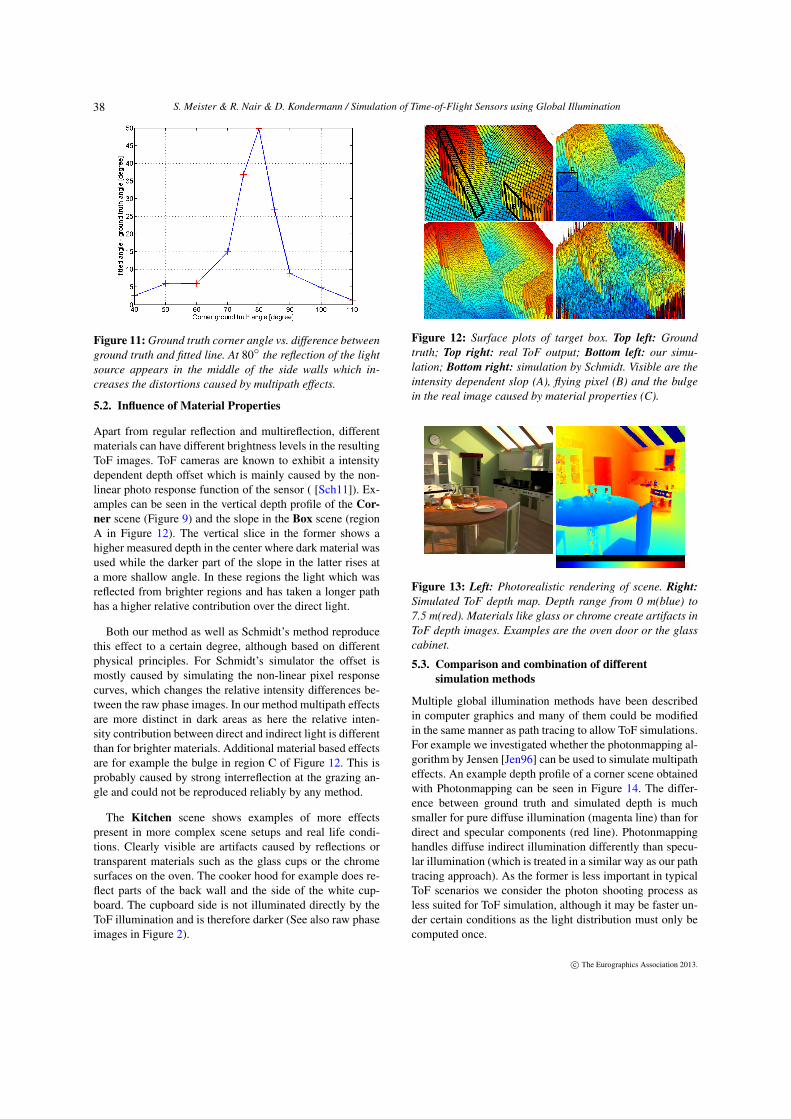
Figure 11: Ground truth corner angle vs. difference between
ground truth and fitted line. At 80◦ the reflection of the light
source appears in the middle of the side walls which in-
creases the distortions caused by multipath effects.
5.2. Influence of Material Properties
Apart from regular reflection and multireflection, differentmaterials can have different brightness levels in the resultingToF images. ToF cameras are known to exhibit a intensitydependent depth offset which is mainly caused by the non-linear photo response function of the sensor ( [Sch11]). Ex-amples can be seen in the vertical depth profile of the Cor-
ner scene (Figure 9) and the slope in the Box scene (regionA in Figure 12). The vertical slice in the former shows ahigher measured depth in the center where dark material wasused while the darker part of the slope in the latter rises ata more shallow angle. In these regions the light which wasreflected from brighter regions and has taken a longer pathhas a higher relative contribution over the direct light.
Both our method as well as Schmidt’s method reproducethis effect to a certain degree, although based on differentphysical principles. For Schmidt’s simulator the offset ismostly caused by simulating the non-linear pixel responsecurves, which changes the relative intensity differences be-tween the raw phase images. In our method multipath effectsare more distinct in dark areas as here the relative inten-sity contribution between direct and indirect light is differentthan for brighter materials. Additional material based effectsare for example the bulge in region C of Figure 12. This isprobably caused by strong interreflection at the grazing an-gle and could not be reproduced reliably by any method.
The Kitchen scene shows examples of more effectspresent in more complex scene setups and real life condi-tions. Clearly visible are artifacts caused by reflections ortransparent materials such as the glass cups or the chromesurfaces on the oven. The cooker hood for example does re-flect parts of the back wall and the side of the white cup-board. The cupboard side is not illuminated directly by theToF illumination and is therefore darker (See also raw phaseimages in Figure 2).
Figure 12: Surface plots of target box. Top left: Ground
truth; Top right: real ToF output; Bottom left: our simu-
lation; Bottom right: simulation by Schmidt. Visible are the
intensity dependent slop (A), flying pixel (B) and the bulge
in the real image caused by material properties (C).
Figure 13: Left: Photorealistic rendering of scene. Right:
Simulated ToF depth map. Depth range from 0 m(blue) to
7.5 m(red). Materials like glass or chrome create artifacts in
ToF depth images. Examples are the oven door or the glass
cabinet.
5.3. Comparison and combination of different
simulation methods
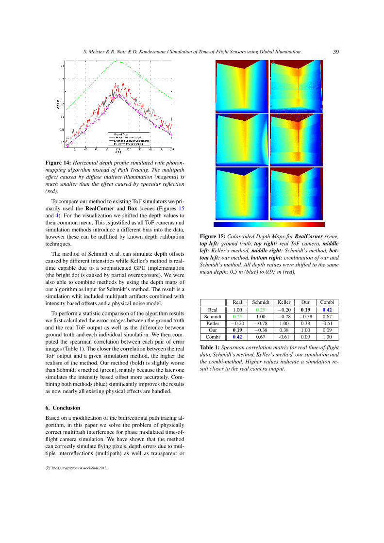
Multiple global illumination methods have been describedin computer graphics and many of them could be modifiedin the same manner as path tracing to allow ToF simulations.For example we investigated whether the photonmapping al-gorithm by Jensen [Jen96] can be used to simulate multipatheffects. An example depth profile of a corner scene obtainedwith Photonmapping can be seen in Figure 14. The differ-ence between ground truth and simulated depth is muchsmaller for pure diffuse illumination (magenta line) than fordirect and specular components (red line). Photonmappinghandles diffuse indirect illumination differently than specu-lar illumination (which is treated in a similar way as our pathtracing approach). As the former is less important in typicalToF scenarios we consider the photon shooting process asless suited for ToF simulation, although it may be faster un-der certain conditions as the light distribution must only becomputed once.
c© The Eurographics Association 2013.
38
S. Meister & R. Nair & D. Kondermann / Simulation of Time-of-Flight Sensors using Global Illumination
Figure 14: Horizontal depth profile simulated with photon-
mapping algorithm instead of Path Tracing. The multipath
effect caused by diffuse indirect illumination (magenta) is
much smaller than the effect caused by specular reflection
(red).
To compare our method to existing ToF simulators we pri-marily used the RealCorner and Box scenes (Figures 15and 4). For the visualization we shifted the depth values totheir common mean. This is justified as all ToF cameras andsimulation methods introduce a different bias into the data,however these can be nullified by known depth calibrationtechniques.
The method of Schmidt et al. can simulate depth offsetscaused by different intensities while Keller’s method is real-time capable due to a sophisticated GPU implementation(the bright dot is caused by partial overexposure). We werealso able to combine methods by using the depth maps ofour algorithm as input for Schmidt’s method. The result is asimulation whit included multipath artifacts combined withintensity based offsets and a physical noise model.
To perform a statistic comparison of the algorithm resultswe first calculated the error images between the ground truthand the real ToF output as well as the difference betweenground truth and each individual simulation. We then com-puted the spearman correlation between each pair of errorimages (Table 1). The closer the correlation between the realToF output and a given simulation method, the higher therealism of the method. Our method (bold) is slightly worsethan Schmidt’s method (green), mainly because the later onesimulates the intensity based offset more accurately. Com-bining both methods (blue) significantly improves the resultsas now nearly all existing physical effects are handled.
6. Conclusion
Based on a modification of the bidirectional path tracing al-gorithm, in this paper we solve the problem of physicallycorrect multipath interference for phase modulated time-of-flight camera simulation. We have shown that the methodcan correctly simulate flying pixels, depth errors due to mul-tiple interreflections (multipath) as well as transparent or
Figure 15: Colorcoded Depth Maps for RealCorner scene,
top left: ground truth, top right: real ToF camera, middle
left: Keller’s method, middle right: Schmidt’s method, bot-
tom left: our method, bottom right: combination of our and
Schmidt’s method. All depth values were shifted to the same
mean depth: 0.5 m (blue) to 0.95 m (red).
Real Schmidt Keller Our Combi
Real 1.00 0.25 −0.20 0.19 0.42
Schmidt 0.25 1.00 −0.78 −0.38 0.67Keller −0.20 −0.78 1.00 0.38 -0.61Our 0.19 −0.38 0.38 1.00 0.09
Combi 0.42 0.67 -0.61 0.09 1.00
Table 1: Spearman correlation matrix for real time-of-flight
data, Schmidt’s method, Keller’s method, our simulation and
the combi-method. Higher values indicate a simulation re-
sult closer to the real camera output.
c© The Eurographics Association 2013.
39

S. Meister & R. Nair & D. Kondermann / Simulation of Time-of-Flight Sensors using Global Illumination
strongly reflecting materials based on the scene geometry.Furthermore, it is able to simulate time-of-flight depth dis-tortions caused by different materials in the scene. Our sim-ulation is so far the only one which accounts for all theseeffects, although it does not yet address all problems likeintensity dependent offsets or wiggling errors. However wehave shown that our simulation method can be combinedwith other sophisticated sensor simulation methods to covera wider field of ToF related problems. By taking into con-sideration the physical and geometric setup of a scene wecan create more realistic images and depth maps for statisti-cal analysis, evaluation, denoising and test of time-of-flightcameras. This enables researchers and practitioners to createsynthetic test datasets for various environmental conditions,scenes or resolutions without the need of a real camera setup.
Future work will concentrate on optimizing the computa-tional efficiency of the rendering process. An option wouldbe to create all phase images simultaneously instead of us-ing four distinct renderings at the cost of simulating motionartifacts. Additionally, more complex material shaders couldsimulate the physically correct behavior under infrared illu-mination or effects such as the bulge in Fig. 12 region C.
The modified LuxRender code will be made available onour website (http://hci.iwr.uni-heidelberg.de/Benchmarks/) according to the GNU General Pub-lic License.
References
[Bra00] BRADSKI G.: The OpenCV Library. Dr. Dobb’s Journal
of Software Tools (2000). 4
[Cen] CENOBI, BLENDSWAP COMMUNITY: Kitchen scene. Dis-tributed under the Creative Commons Attribution-ShareAlike 3.0license http://www.blendswap.com/blends/view/
62683. 4
[DGC∗11] DORRINGTON A., GODBAZ J., CREE M., PAYNE A.,STREETER L.: Separating true range measurements from multi-path and scattering interference in commercial range cameras. InIS&T/SPIE Electronic Imaging (2011), International Society forOptics and Photonics. 2
[EJ09] ERZ M., JÄHNE B.: Radiometric and spectrometric cali-brations, and distance noise measurement of ToF cameras. Dy-
namic 3D Imaging (2009), 28–41. 3
[FB08] FALIE D., BUZULOIU V.: Distance errors correction forthe time of flight (ToF) cameras. In Imaging Systems and Tech-
niques, 2008. IST 2008. IEEE International Workshop on (2008),IEEE, pp. 123–126. 2
[Fuc10] FUCHS S.: Multipath interference compensation in time-of-flight camera images. In Pattern Recognition (ICPR), 2010
20th International Conference on (2010), IEEE. 2
[Gor82] GORDON H. R.: Interpretation of airborne oceanic li-dar: effects of multiple scattering. Applied Optics 21, 16 (1982),2996–3001. 2
[ICG86] IMMEL D., COHEN M., GREENBERG D.: A radiositymethod for non-diffuse environments. In ACM SIGGRAPH Com-
puter Graphics (1986), vol. 20, ACM, pp. 133–142. 3
[Jen96] JENSEN H.: Global illumination using photon maps. Ren-
dering Techniques 96 (1996), 21–30. 6
[JPMP12] JIMÉNEZ D., PIZARRO D., MAZO M., PALAZUELOS
S.: Modelling and correction of multipath interference in timeof flight cameras. In Computer Vision and Pattern Recognition
(CVPR), 2012 IEEE Conference on (2012), IEEE. 2
[Kaj86] KAJIYA J.: The rendering equation. ACM SIGGRAPH
Computer Graphics 20, 4 (1986), 143–150. 3
[KGP12] KAREL W., GHUFFAR S., PFEIFER N.: Modelling andCompensating Internal Light Scattering in Time of Flight RangeCameras. The Photogrammetric Record 27, 138 (2012). 2
[KK09] KELLER M., KOLB A.: Real-time simulation of time-of-flight sensors. Simulation Modelling Practice and Theory 17, 5(2009), 967–978. 2, 4
[KOKP07] KELLER M., ORTHMANN J., KOLB A., PETERS V.:A simulation framework for time-of-flight sensors. In Signals,
Circuits and Systems, 2007. ISSCS 2007. International Sympo-
sium on (2007), vol. 1, IEEE, pp. 1–4. 2
[KW76] KUNKEL K. E., WEINMAN J.: Monte carlo analysis ofmultiply scattered lidar returns. Journal of Atmospheric Sciences
33 (1976), 1772–1781. 2
[L] LuxRender: GPL Physically Based Renderer.http://www.luxrender.net. URL: http://www.luxrender.net. 3
[LK07] LINDNER M., KOLB A.: Calibration of the intensity-related distance error of the PMD ToF-camera. In Proc.
SPIE, Intelligent Robots and Computer Vision (2007), vol. 6764,p. 67640W. 2
[LW93] LAFORTUNE E. P., WILLEMS Y. D.: Bi-directionalpath tracing. In Proceedings of CompuGraphics (1993), vol. 93,pp. 145–153. 3
[MK11] MEISTER S., KONDERMANN D.: Real versus realis-tically rendered scenes for optical flow evaluation. In Elec-
tronic Media Technology (CEMT), 2011 14th ITG Conference on
(2011), IEEE, pp. 1–6. 1
[PH10] PHARR M., HUMPHREYS G.: Physically based render-
ing: From theory to implementation. Morgan Kaufmann, 2010.3
[Pla06] PLAUE M.: Analysis of the PMD Imaging System.Tech. rep., Interdisciplinary Center for Scientific Comput-ing,University of Heidelberg, 2006. 2
[RFHJ08] RAPP H., FRANK M., HAMPRECHT F., JAHNE B.: Atheoretical and experimental investigation of the systematic er-rors and statistical uncertainties of Time-Of-Flight-cameras. In-
ternational Journal of Intelligent Systems Technologies and Ap-
plications 5, 3 (2008), 402–413. 3
[Sch11] SCHMIDT M.: Analysis, Modeling and Dynamic Opti-
mization of 3D Time-of-Flight Imaging Systems. PhD thesis, Uni-versity of Heidelberg, 20011. 2, 4, 6
[Sch08] SCHMIDT M.: Spatiotemporal Analysis of Range Im-
agery. PhD thesis, University of Heidelberg, 2008. 2
[SSD07] SMITH A., SKORUPSKI J., DAVIS J.: Transient render-
ing. Tech. rep., School of Engineering, University of California,2007. 2
[VG95] VEACH E., GUIBAS L.: Bidirectional estimators forlight transport. In Photorealistic Rendering Techniques. Springer,1995, pp. 145–167. 3
[WBSB12] WULFF J., BUTLER D. J., STANLEY G. B., BLACK
M. J.: Lessons and insights from creating a synthetic opticalflow benchmark. In ECCV Workshop on Unsolved Problems in
Optical Flow and Stereo Estimation (oct 2012), A. Fusiello et al.(Eds.), (Ed.), Part II, LNCS 7584, Springer-Verlag, pp. 168–177.1
c© The Eurographics Association 2013.
40