3d time of flight sensors for robot navigation
DESCRIPTION
3D Time of Flight Sensors for Robot Navigation. Mohammed Rizwan Adil, Chidambaram Alagappan., and Swathi Dumpala Basaveswara. Robots. Gaining immense importance Presence of robots being felt in all walks of life. Image detection has become a prerequisite for effective navigation. - PowerPoint PPT PresentationTRANSCRIPT

Mohammed Rizwan Adil, Chidambaram Alagappan., and Swathi Dumpala
Basaveswara

RobotsGaining immense importance Presence of robots being felt in all walks of
life. Image detection has become a prerequisite
for effective navigation. The robot should be able to ‘extract’ all the
necessary information from its sensors.

Image detection Conventional 2D images detect brightness but
don’t detect depth. Therefore 3D Time of Flight Cameras are being
used. The depth information is depicted using color
codes. 3D ToF cameras combine the accurate distance
measurements and camera based system. A final discussion about PMD and the psuedo
four phase shift algorithm
Introduction Four building blocks of navigation 1. perception-robot must be able to interpret
meaningful data using the sensors2. localization- the robot must be able to
determine its position with regard to the environment
3. cognition- the robot must be able to determine its path
4. motion control- the mechanical traversal along the planned path
Simultaneous Localization and Mapping (SLAM) [3].
In most cases, the processes of exploring an unknown environment through maps and determining the relative position are performed simultaneously through a process known as Simultaneous Localization and Mapping
Several methods to obtainb 3D images An image from stereo vision camera which
provides 3D details of an object can be fused with the measurements of a 2D laser range finder.
Stereo vision requires complicated algorithms and powerful sensors to construct its occupancy grid and despite all these, it is prone to error

SfM= Structure from Motion Works assuming that the object is going to
move. Trajectories of points are used to estimate
dimensions. Technique will not work if object is
dynamic(like flowing water)
Stereo Vision v/s Kinetic depth techniqueIn Stereo Vision, the image and the data from
the laser range finders corresponding to the same time has to be overlapped to obtain a 3D vision.
In Kinetic depth technique, the image of the same object has to be taken at two different time intervals- either ways, both techniques require data fusion which requires computing power.
Laser Range Scanners Laser Range Scanner which works on the
principle of calculating the distance from the observer to a particular point.
Laser Range Scanners provide sparse data sets, use mechanical components and do not provide a 3D image with one image capture

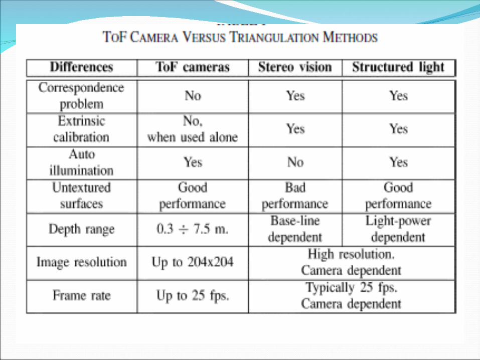
ToF cameras The time of flight cameras combine the
features of active range sensors and camera based approaches and provide a complex image which contains both the intensities and also the distances of each and every point.
There is no fusion of data from two separate sources and the data is being gathered continuously
Principle behind the time of flight cameras
Points that are distant from the camera will take greater time to reach it.
The distance to the object us calculated using properties of light and phase shift of modulation envelope of the light source.
The phase and amplitude of the reflected light can be detected using various signal processing techniques. Usually, to get a high resolution CCD based sensors are employed

CMOS ToF camera CMOS chip based cameras appear most
widely in the literature.

CMOS sensors usually have 64x64 pixel array and are implemented on a single chip using ordinary, low cost CMOS process.
It also needs to have ADC and also a mechanism to generate high speed modulation signals
The main part of the sensor design is the unique pixel structure

Unique pixel structure
The differential structure accumulates photogenerated charges in two collection nodes using two modulated gates.
The gate modulation signals are synchronized with the light source, and hence depending on the phase of incoming light, one node collects more charges than the other.
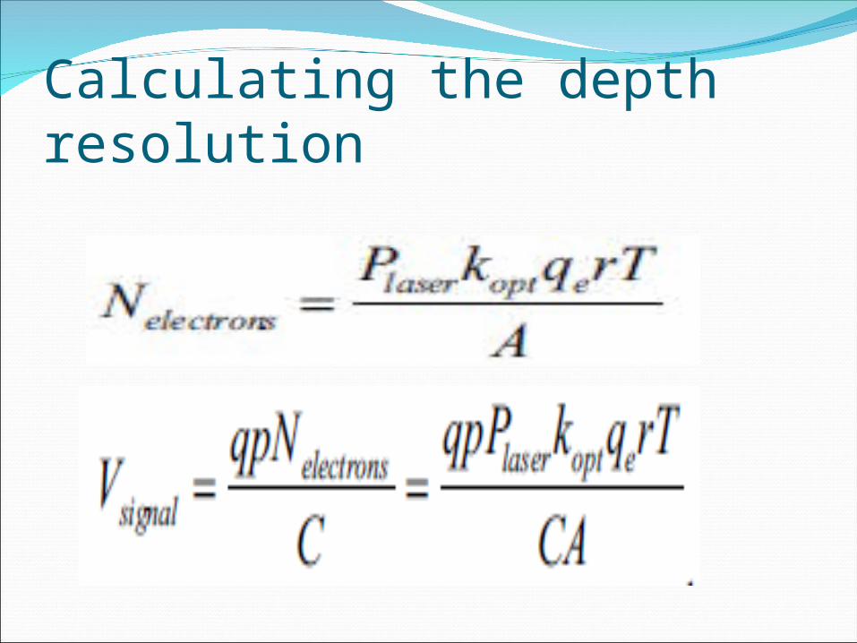
Calculating the depth resolution
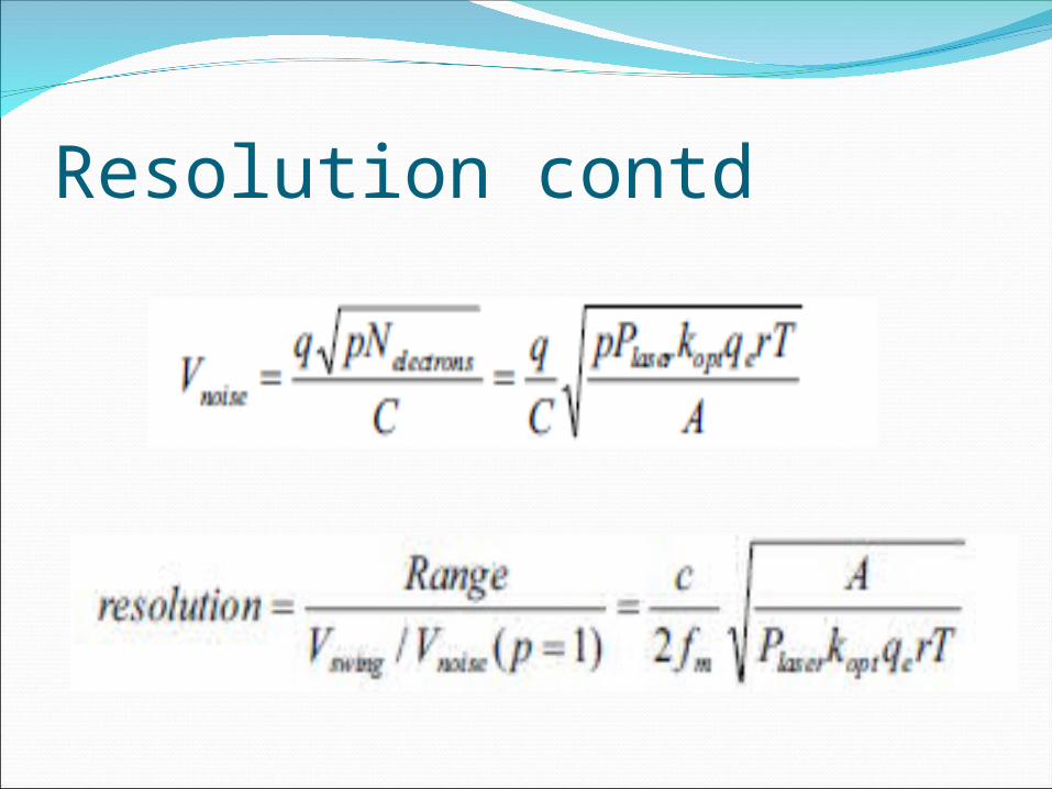
Resolution contd

Enhancement of Depth ImagesOptical noise existence, unmatched boundaries,
and temporal inconsistency are the three critical problems which a ToF image suffers from.
Techniques like Gaussian smoothing and quadratic Bezier curve are used for static 3D images
However, for enhancement of dynamic images, we use newly designed joint bilateral filtering, color segmentation based boundary refinement, and motion estimation based temporal consistency.
Bilateral Filter Constructed using both color and depth
information at the same time. After color segmenting a color image, we
extract the color segment set to detect object boundaries.
To minimize temporal depth flickering artifacts on stationary objects, we match previous and current frame color images.
Review of latest developments These cameras are able to provide registered
dense depth and intense images, complete image acquisition and high frame rate, small and compact design.
They don’t need any mobile parts and have auto-illumination


Errors and Compensations for ToF cameras Systematic Errors: 1. Depth Distortion 2. Integrated time related error 3. Built in pixel related errors4. Amplitude related errors5. Temperature related errors
Non Systematic Errors 1. SNR 2. Multiple light reception 3. Light scattering 4. Motion blurring
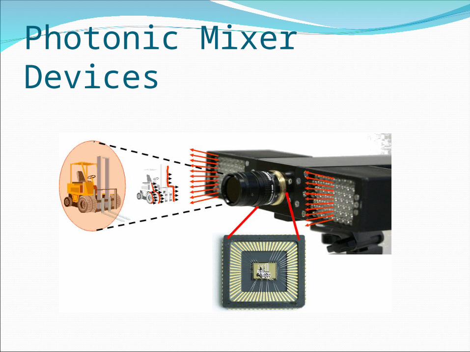
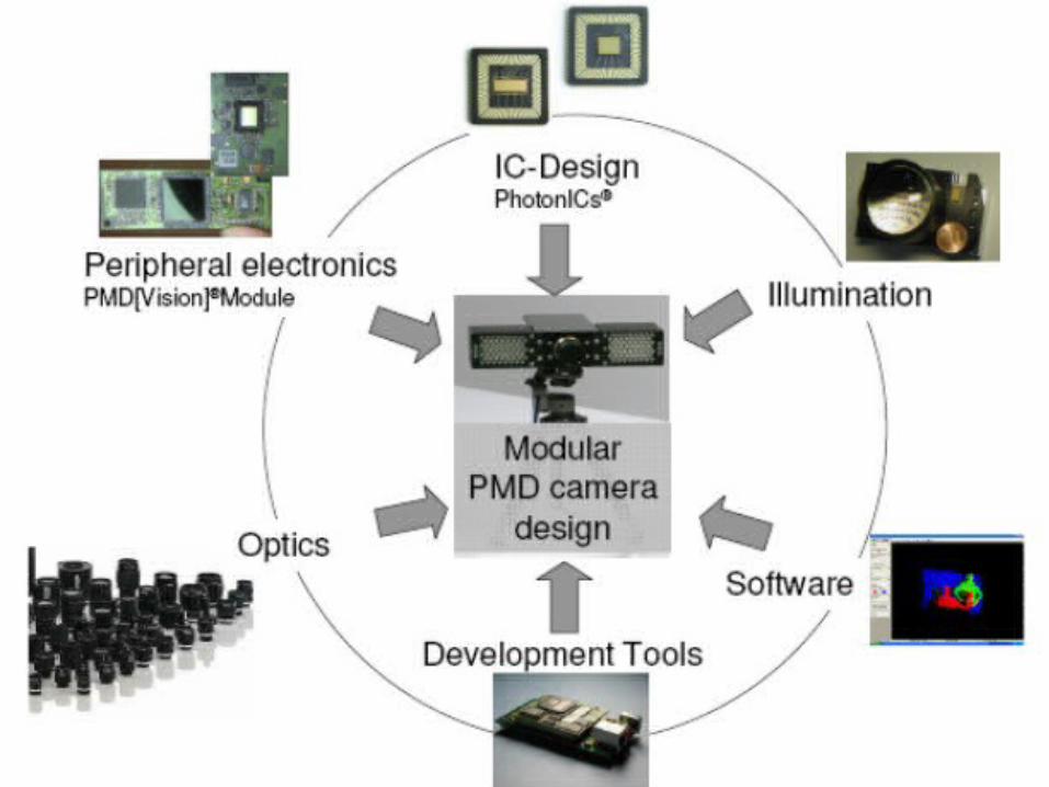
Photonic Mixer Devices

PMD cont’d Photonic Mixer Devices are also based on
ToF principle and can realize a 3D image without complex electronics similar to a CMOS device
In a PMD, instead of a single laser beam (which would have to be scanned over the scene to obtain 3D) the entire scene is illuminated with modulated light.

Pseudo-Four-Phase-Shift Algorithm for PerformanceEnhancement of 3D-TOF Vision Systems
Only two image captures instead of four are required to calculate the phase difference φ.
The frame rate of PMD TOF sensors is doubled without changing the integration time Tint .

Thanks