simulation and verification of pulse doppler radar...
TRANSCRIPT

Copyright © 2010 Agilent Technologies
Simulation and Verification of Pulse Doppler Radar Systems
Author: Dingqing Lu, Agilent Technologies

Copyright © 2010 Agilent Technologies
2
Agenda
– Radar System Design Challenges– Signal Processing Algorithm Creation– Examples
• Pulsed Doppler (PD) Radar– Wrap up

Copyright © 2010 Agilent Technologies
3
System Design Challenges
– Advanced radar systems are very complex– It is based on radar signal processing algorithms– Algorithm creation requires a platform for simulation
and verification – Enough models for signal generation, transmission,
antenna, T/R switching, clutter, noise, jamming, receiving, signal processing and measurements are needed to create the advanced algorithm

Copyright © 2010 Agilent Technologies
4
Signal Processing Algorithm Creation
– System Platform is needed for both design and verification
– The Platform can provide• Algorithm design/verification environment for signal generation
and performance measurements• User-friendly algorithm modeling & debug environment
supporting variety of languages such as C++, Math Lang • Interface to test equipment to verify the implemented
hardware (compared to the original pure algorithm)– Test sources include radar signal generation with RCS,
Clutter, Jamming, Doppler frequency offset– Measurements include waveforms, spectra, detection rate,
false alarm rate (FAR).

Copyright © 2010 Agilent Technologies
5
Platform for Simulation
Tx Waveform Library
T/R ComponentLibrary Antenna Library
• Radar Pulse Generator• Coherent Signal Generator for Single or Multiple Channel
• DAC• PA• Up Converter• Filter• DDS• LNA• Down Converter• ADC
Radar Environment Radar Signal Processing Library
• Antenna Models• T/R Antenna Array• Antenna Propagation
• Target• Clutter• Jammer• Interference
• Digital Pulse Compression• Moving Target Indication (MTI)• Moving Target Detection (MTD)• Constant False Alarm Rate (CFAR) • Digital Beamformer• Space-Time Adaptive
Processing (STAP)

Copyright © 2010 Agilent Technologies
6
Platform for Verification
Signal ProcessorHardware
ESG/PSG/MXG PSA/MXA/VSALA, Scope
Copyright © 2010 Agilent Technologies
7
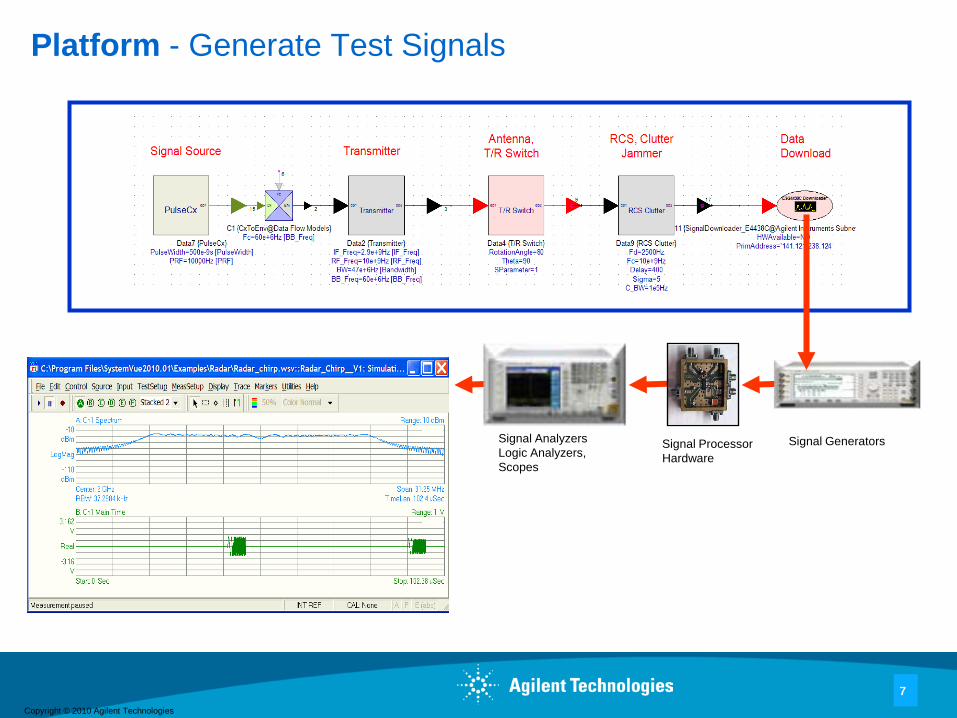
Platform - Generate Test Signals
Signal ProcessorHardware
Signal GeneratorsSignal AnalyzersLogic Analyzers, Scopes
Copyright © 2010 Agilent Technologies
8
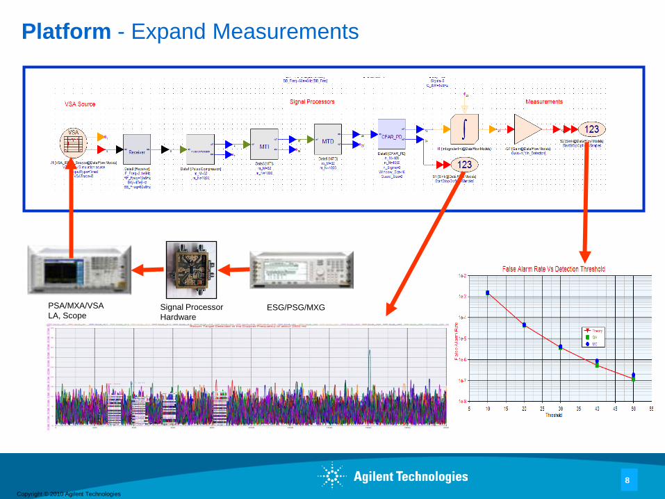
Platform - Expand Measurements
Signal ProcessorHardware
ESG/PSG/MXGPSA/MXA/VSALA, Scope
Copyright © 2010 Agilent Technologies
9
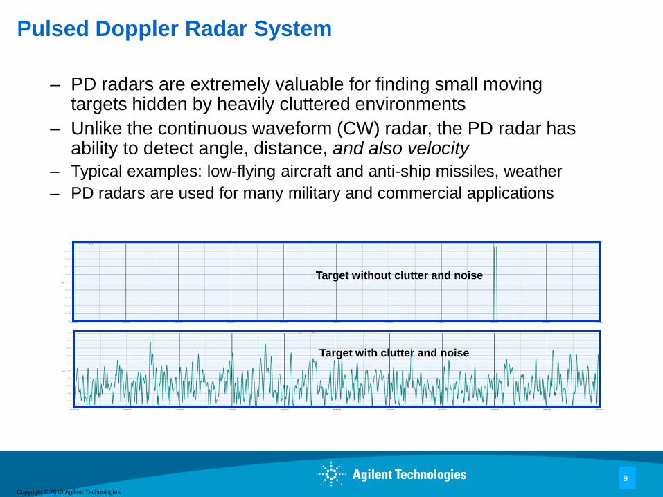
Pulsed Doppler Radar System
– PD radars are extremely valuable for finding small moving targets hidden by heavily cluttered environments
– Unlike the continuous waveform (CW) radar, the PD radar has ability to detect angle, distance, and also velocity
– Typical examples: low-flying aircraft and anti-ship missiles, weather– PD radars are used for many military and commercial applications
Target without clutter and noise
Target with clutter and noise

Copyright © 2010 Agilent Technologies
10
PD Radar System – In Principle
– The Radar Transmission signal and Returned signal [1,2] are given by
– Cannot detect the target in time domain because small moving targets are hidden by heavily cluttered environments
– Must detect the signal in frequency domain using the Doppler frequency analysis
– We must collect return data and process in both range and frequency domain for estimating and .
– 2-dimensional signal processing is required for moving target indicator (MTI) and moving target detection (MTD).
– Constant false alarm rate (CFAR) processing is needed for auto-detection in PD process. Without CFAR, auto-detection will fail.
)2()()( tfCostAtS cπ=
)()()())(2()()( tNtNtNtffCostAtS jnCdc +++−+=− τπτ
τ^
df^

Copyright © 2010 Agilent Technologies
11
PD Radar System – In Principle
2-D data matrix of coherent, baseband returns for M pulses• Fast time sample rate is 10^5 to 10^8 samples/sec• Slow time sample rate is the PRF, 10^3 to 10^5
samples/sec • Collected using the pulse burst waveform
Fast Time (R
ange bins)
Slow Time (for Doppler Frequency)
Sampling Interval= 1/BW
Sampling Interval= PRI

Copyright © 2010 Agilent Technologies
12
PD Radar System – In Principle
– To extract the Doppler frequency and the target delay 2D signal processing is needed
• Doppler processing operates on each row of this MatrixTwo major processing
– MTI applies a linear filter to each row– PD applies a spectrum estimation to each row
Range bins
For Doppler Frequency
MTI filteringOr spectraEstimation forDoppler Freq

Copyright © 2010 Agilent Technologies
13
PD Radar System Structure
– For PD, based on the generic radar system structure (shown in slide 5), the signal processors include Pulse Compression, MTI, MTD and CFAR

Copyright © 2010 Agilent Technologies
14
PD Radar System – Signal Source Models
Signal sources include:• Pulse signal generator • Linear FM pulse signal generator• Nonlinear FM signal generator• Polyphase code generator
Example LFM Pulse Signal Generator
Copyright © 2010 Agilent Technologies
15
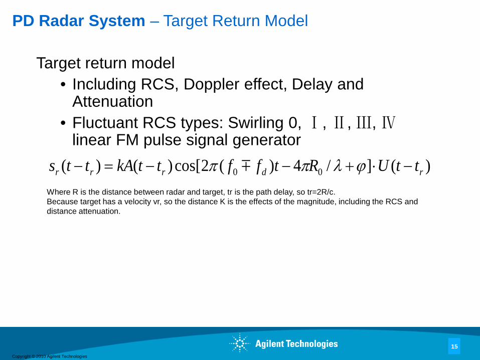
PD Radar System – Target Return Model
Target return model• Including RCS, Doppler effect, Delay and
Attenuation• Fluctuant RCS types: Swirling 0, Ⅰ, Ⅱ, Ⅲ, Ⅳ
linear FM pulse signal generator)(]/4)(2cos[)()( 00 rdrrr ttURtffttkAtts −⋅+−−=− ϕλππ
Where R is the distance between radar and target, tr is the path delay, so tr=2R/c. Because target has a velocity vr, so the distance K is the effects of the magnitude, including the RCS and distance attenuation.
Copyright © 2010 Agilent Technologies
16
PD Radar System – Clutter
Choice of 4 amplitude probability distribution functions (PDF) and 3 power spectrum density (PSD) functions
• PDF– Rayleigh– Log-Normal– Weibull– K – Distribution
• PSD– Gaussian– Cauchy– All Pole
Copyright © 2010 Agilent Technologies
17
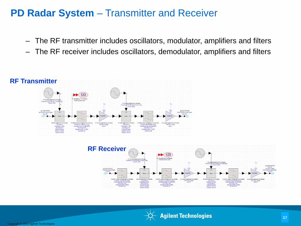
PD Radar System – Transmitter and Receiver
– The RF transmitter includes oscillators, modulator, amplifiers and filters– The RF receiver includes oscillators, demodulator, amplifiers and filters
RF Transmitter
RF Receiver
Copyright © 2010 Agilent Technologies
18
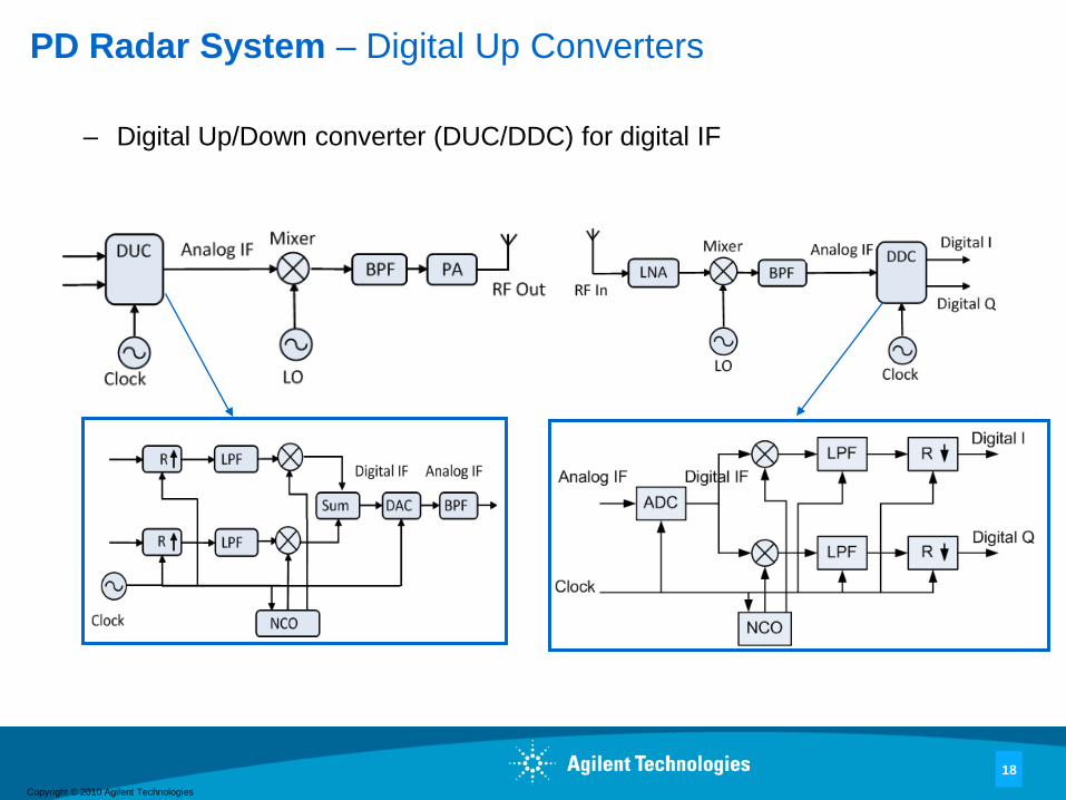
PD Radar System – Digital Up Converters
– Digital Up/Down converter (DUC/DDC) for digital IF
Copyright © 2010 Agilent Technologies
19
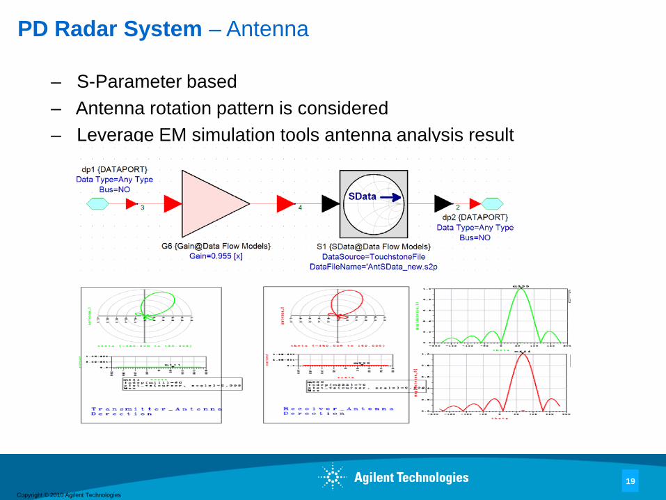
PD Radar System – Antenna
– S-Parameter based– Antenna rotation pattern is considered – Leverage EM simulation tools antenna analysis result
Antenna Model

Copyright © 2010 Agilent Technologies
20
PD Radar System – Pulse Compression

Copyright © 2010 Agilent Technologies
21
PD Radar System – Moving Target Indicator
– The basic idea for the moving target indicator (MTI) is to filter the clutter at DC or very near DC but keep the other spectrum region remaining flat
– A three-pulse (double, second-order) canceller can be formed by cascading two first-order sections
– Transfer function
2121)( −− +−= zzzH
Copyright © 2010 Agilent Technologies
22
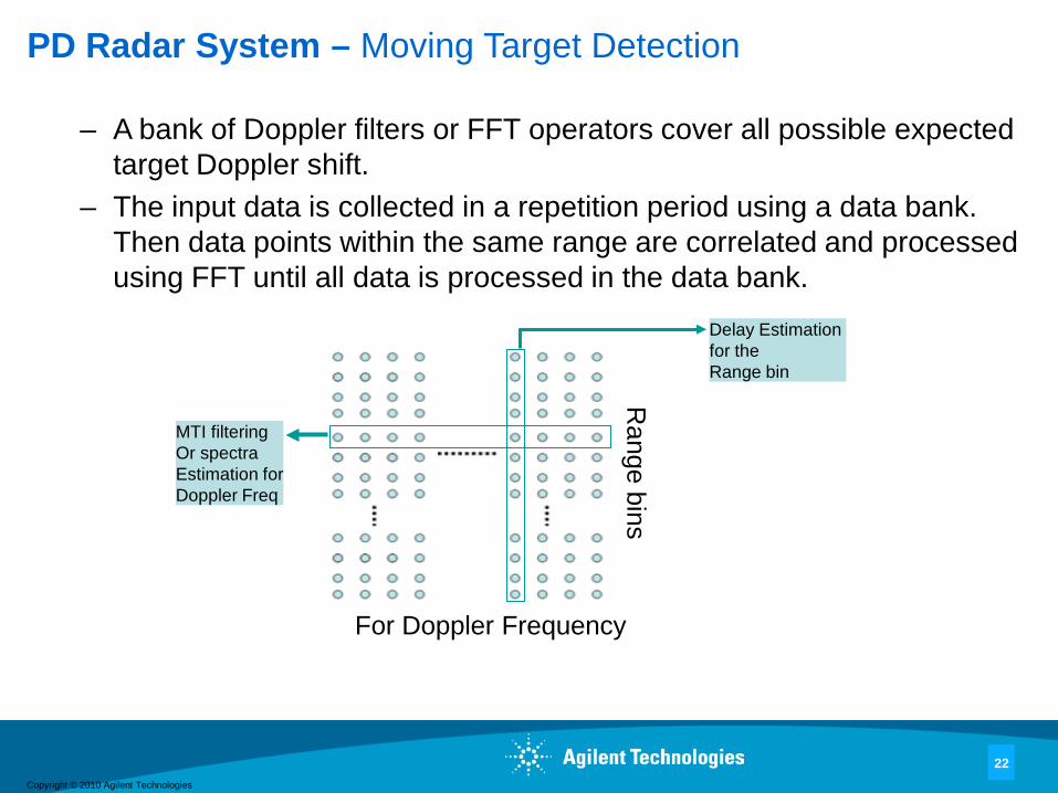
PD Radar System – Moving Target Detection
– A bank of Doppler filters or FFT operators cover all possible expected target Doppler shift.
– The input data is collected in a repetition period using a data bank. Then data points within the same range are correlated and processed using FFT until all data is processed in the data bank.
Range bins
For Doppler Frequency
MTI filteringOr spectraEstimation forDoppler Freq
Delay Estimation for the Range bin
Copyright © 2010 Agilent Technologies
23
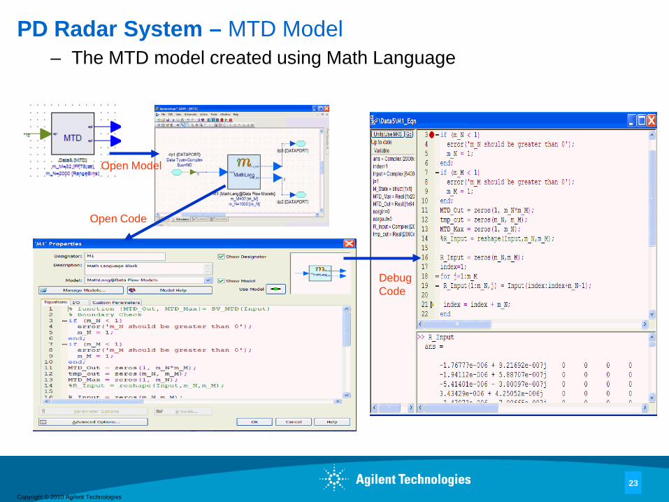
PD Radar System – MTD Model– The MTD model created using Math Language
Open Model
Open Code
Debug Code
Copyright © 2010 Agilent Technologies
24
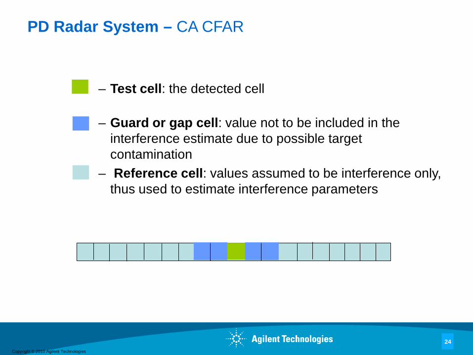
PD Radar System – CA CFAR
– Test cell: the detected cell
– Guard or gap cell: value not to be included in the interference estimate due to possible target contamination
– Reference cell: values assumed to be interference only, thus used to estimate interference parameters
Copyright © 2010 Agilent Technologies
25
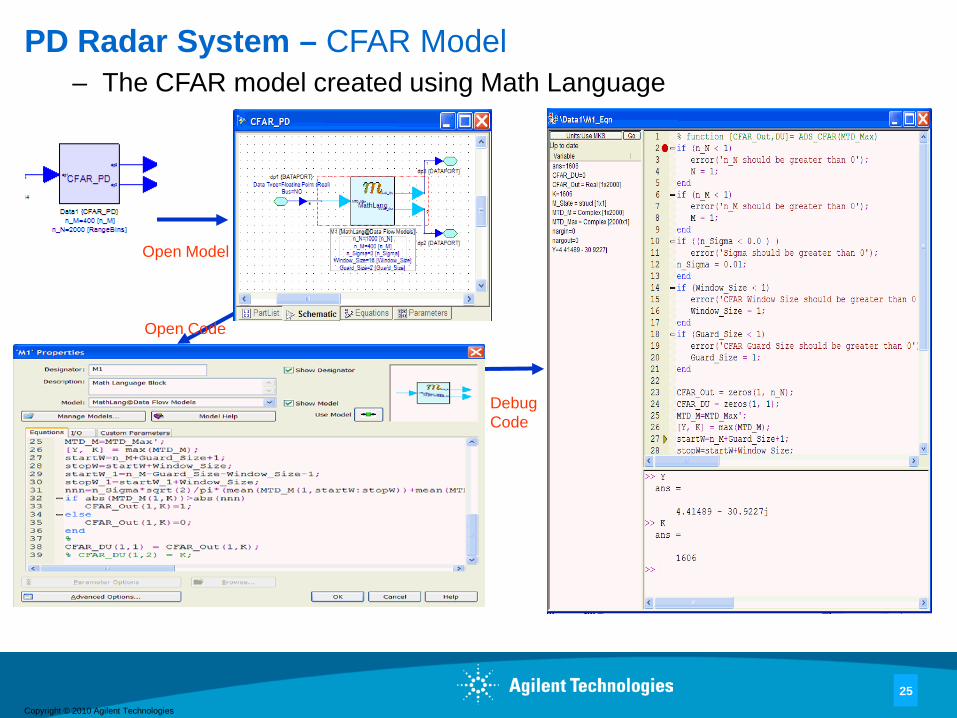
PD Radar System – CFAR Model– The CFAR model created using Math Language
Open Model
Debug Code
Open Code
Copyright © 2010 Agilent Technologies
26
PD Radar System – Measurements
– Basic measurements• Waveform• Spectrum • Signal Noise Ratio
– Advanced measurements• Estimation of Distances and Speed• Detection probabilityPd = Number of Successful detection / Total number of Tests • False Alarm probabilityPf = Number of False Error / Total Number of TestsImportance sampling will be used to speed up the Pf simulation [3].

Copyright © 2010 Agilent Technologies
27
PD Radar System – Simulation Setup– All key parameters can be set in the parameter table defined for
the PD simulation system as seen as below. User can very easily edit, add or delete any parameter.
Copyright © 2010 Agilent Technologies
28
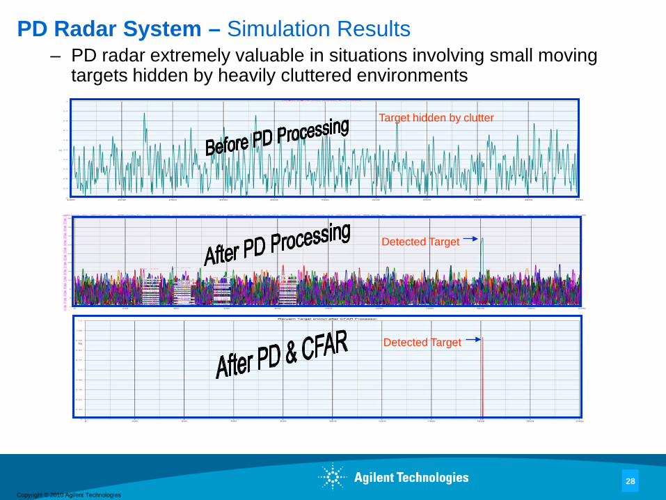
PD Radar System – Simulation Results– PD radar extremely valuable in situations involving small moving
targets hidden by heavily cluttered environments
Detected Target
Detected Target
Target hidden by clutter
Copyright © 2010 Agilent Technologies
29
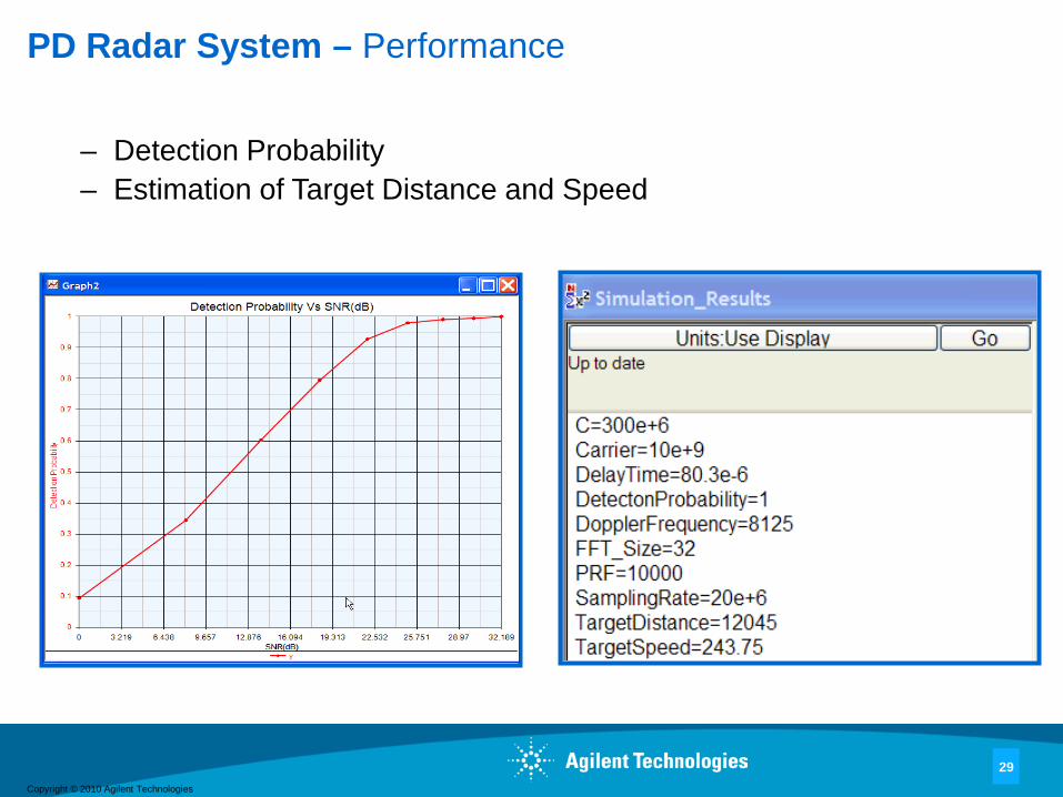
PD Radar System – Performance
– Detection Probability – Estimation of Target Distance and Speed

Copyright © 2010 Agilent Technologies
30
Summary
– Algorithms are critical for high-performing advanced radars– A unified approach using Agilent SystemVue was demonstrated
– Provides a user friendly environment for algorithm development
– Integrates software and hardware to verify algorithms– A development example for PD radar key algorithms was shown– SystemVue can also be used to develop algorithms for Digital
Array Radar plus Space-time adaptive processing (STAP) and MIMO Radar
Copyright © 2010 Agilent Technologies
31
References
1. I. Skolnik, Radar Handbook, 2nd ed. McGraw-Hill,Inc. 19902. D. Curtis Schleher, MTI and Pulse Doppler Radar, Artech
House, Inc. 19913. Dingqing Lu and Kong Yao "Importance Sampling Simulation
Techniques Applied to Estimating False Alarm Probabilities," Proc. IEEE ISCAS, 1989, pp.598-601
Copyright © 2010 Agilent Technologies
For more information aboutAgilent EEsof EDA, visit:
www.agilent.com/find/eesof
For more information on Agilent Technologies’products, applications or services, pleasecontact your local Agilent office. Thecomplete list is available at:
www.agilent.com/find/contactus
Contact Agilent at:
AmericasCanada (877) 894-4414Brazil (11) 4197 3500Mexico 01800 5064 800United States (800) 829-4444
Asia PacificAustralia 1 800 629 485China 800 810 0189Hong Kong 800 938 693India 1 800 112 929Japan 0120 (421) 345Korea 080 769 0800Malaysia 1 800 888 848Singapore 1 800 375 8100Taiwan 0800 047 866Thailand 1 800 226 008
Europe & Middle East
Austria 01 36027 71571Belgium 32 (0) 2 404 93 40Denmark 45 70 13 1515Finland 358 (0) 10 855 2100France 0825 010 700*
*0.125 €/minuteGermany 07031 464 6333Ireland 1890 924 204Israel 972-3-9288-504/544Italy 39 02 92 60 8484Netherlands 31 (0) 20 547 2111Spain 34 (91) 631 3300Sweden 0200-88 22 55Switzerland 0800 80 53 53United Kingdom 44 (0) 118 9276201Other European Countries:www.agilent.com/find/contactus
Product specifications and descriptions in this document subject to change without notice.
© Agilent Technologies, Inc. 2010Printed in USA, October 14, 20105990-6697EN
www.agilent.comwww.agilent.com/find/eesof-systemvue