keysight technologies secondary radar...
TRANSCRIPT
Keysight TechnologiesSecondary Radar TransponderTesting Using the 8990B Peak Power Analyzer
Application Note

Introduction
After a brief review of radar systems and the role of transponders, this application note provides examples of how to effectively test transponders in order to validate their performance and function. Testing is performed using a transponder test set and a Keysight Technologies, Inc. peak performance analyzer (PPA). The measurement examples provided cover interrogation and reply transmit power and pulse profiling, double pulse spacing, and reply delay timing measurement.

03 | Keysight | Secondary Radar Transponder Testing Using the 8990B Peak Power Analyzer - Application Note
Secondary Radar Background
Secondary radar originated from the identification friend or foe (IFF) radar signal system used during World War II and complements the limitations of primary radar systems.
Primary radar works by passively reflecting a radar signal off of the target’s reflection or surfaces (called echoes). A limitation of primary radar is that it has difficulty detecting non-metal or composite-based aircraft parts. Another weakness is weather-related. In heavy rain, reflected signals are prone to attenuation, decreasing detection accuracy.
Secondary radar works by transmitting and receiving high-frequency modulated pulses, also called interrogation and reply signals. Figure 1 illustrates the operating principle of secondary radar systems. It begins when the ground station sends interrogation signals to the airborne aircraft. The plane’s on board transponder responds to the interrogation signals by transmitting back reply signals.
Modern secondary radar systems are used in both civilian and military aviationoperations. The civilian’s secondary radar system is called secondary surveillanceradar (SSR) and it is primarily used for air traffic control such as in the Air Traffic Control Radar Beacon System (ATCRBS) and the Traffic Collision Avoidance System (TCAS). SSR operates in different modes known by letter designators such as Modes A, B, C, D, and S. Rather than alphabetic modes, the military IFF uses numerical modes 1 through 5. The military and civilian modes operate differently but modes 3 and A are similar and mode 5 is an encrypted version of mode S.
Figure 1. Illustration of the secondary radar operating principle
On-board transponder
Reply from transponder
Interrogation fromground station
Groundstation

04 | Keysight | Secondary Radar Transponder Testing Using the 8990B Peak Power Analyzer - Application Note
What is a Transponder and Its Function?
As mentioned previously, transponders are an important part of the secondary radar system. Usually mounted on the under surface of the aircraft’s fuselage, the transponder is basically a transmitter and receiver. As shown in the timing diagram in Figure 2, during operation the transponder receives interrogation pulse pairs from the ground station and decodes the requested enquiries. After a certain delay duration, the transponder then responds with a different series of pulses that contain the information requested by the interrogation transmission. The communication exchanges can include information such as the aircraft identifier, altitude, and bearings. The interrogation and reply pulses use different frequencies, depending on the mode of operation.
Figure 2. Transponder interrogation and reply pulse pairs timing diagram. (Note: When radar is in use, a P2 interrogation pulse is transmitted and ignored. F1 and F2 refer to framing reply pulses.)
Interrogationpulse totransponder
Reply pulsefromtransponder
Double pulse spacing
Reply pulse spacing
Reply delay
P1
F1 F2
P3
05 | Keysight | Secondary Radar Transponder Testing Using the 8990B Peak Power Analyzer - Application Note
Testing and Validating the Transponder’s Performance and Functions Federal aviation safety standards, such as those defined by the US Federal Aviation Administration, require transponders to undergo periodic maintenance and calibration. This precaution ensures that the transponder is decoding interrogation pluses correctly and subsequently replying with correct pulses. The maintenance also includes perfor-mance checks that ensure the transponder transmit/receive functions conform to specifications. Transponder calibrations are typically done using a transponder test sets and the Keysight 8990B peak power analyzer (PPA). Ultimately these maintenance tasks optimize efficiency and minimize the potential for transponder failure during operation. They also ensure compliance with aviation safety standards. A malfunctioning transponder can result in a catastrophic event. From the military operation perspective, a transponder failure such as an incorrect reply can ultimately mean the difference between life or death. The following sections demonstrate how the Keysight 8990 PPA is used to perform transponder and transponder test set maintenance and validation. The measurement examples featured are interrogation and reply transmit power and pulse profiling, double pulse spacing, and reply delay timing measurement.
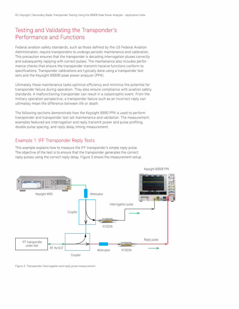
Example 1: IFF Transponder Reply TestsThis example explains how to measure the IFF transponder’s simple reply pulse.The objective of the test is to ensure that the transponder generates the correctreply pulses using the correct reply delay. Figure 3 shows the measurement setup.
Figure 3. Transponder interrogation and reply pulse measurement
Keysight 8990B PPA
Interrogation pulse
Keysight MXG
Reply pulse
Coupler
Coupler
IFF transponderunder test
RF IN/OUT
Attenuator
Attenuator
N1923A
N1923A
06 | Keysight | Secondary Radar Transponder Testing Using the 8990B Peak Power Analyzer - Application Note
Example 1: IFF Transponder Reply Tests (continued)
1. Connect the transponder under test to a signal generator using directional couplers.
2. Using pulse building software such as Keysight N7620A Signal Studio, construct interro-gation pulses according to the operating modes as shown in Table 1. In this application example, the transponder is set to operate using Mode 1 for the interrogation and reply test.
3. Downloaded the pulses created to the signal generator to produce the respective interrogation pulses, which are sent to the transponder under test.
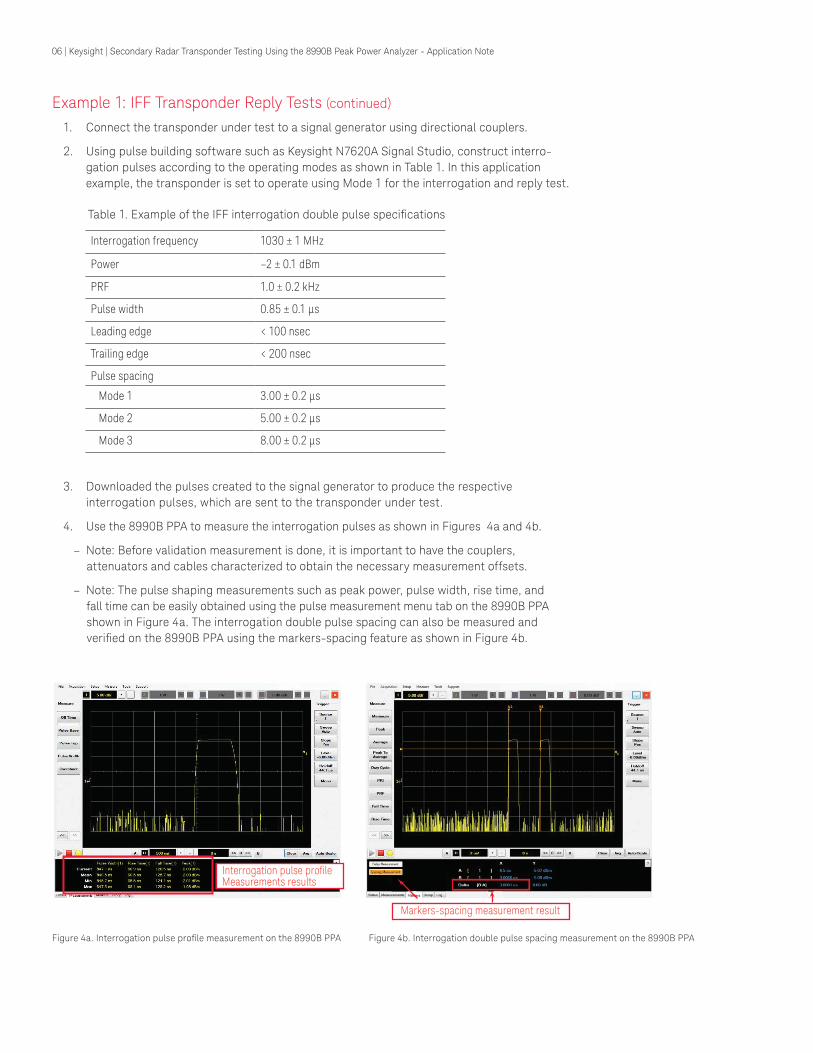
4. Use the 8990B PPA to measure the interrogation pulses as shown in Figures 4a and 4b.
– Note: Before validation measurement is done, it is important to have the couplers, attenuators and cables characterized to obtain the necessary measurement offsets.
– Note: The pulse shaping measurements such as peak power, pulse width, rise time, and fall time can be easily obtained using the pulse measurement menu tab on the 8990B PPA shown in Figure 4a. The interrogation double pulse spacing can also be measured and verified on the 8990B PPA using the markers-spacing feature as shown in Figure 4b.
Figure 4a. Interrogation pulse profile measurement on the 8990B PPA Figure 4b. Interrogation double pulse spacing measurement on the 8990B PPA
Interrogation frequency 1030 ± 1 MHz
Power –2 ± 0.1 dBm
PRF 1.0 ± 0.2 kHz
Pulse width 0.85 ± 0.1 μs
Leading edge < 100 nsec
Trailing edge < 200 nsec
Pulse spacing
Mode 1 3.00 ± 0.2 μs
Mode 2 5.00 ± 0.2 μs
Mode 3 8.00 ± 0.2 μs
Table 1. Example of the IFF interrogation double pulse specifications
Interrogation pulse profile Measurements results
Markers-spacing measurement result
07 | Keysight | Secondary Radar Transponder Testing Using the 8990B Peak Power Analyzer - Application Note
Example 2: IFF Transponder’s Reply Pulses Tests1. Once the interrogation pulse is transmitted to the transponder under test, the
transponder will generate a reply double pulse within a certain time delay. For this example, the IFF transponder reply pulse specifications are shown in Table 2.
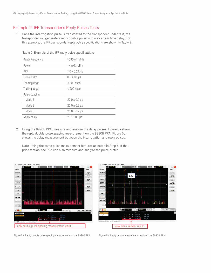
2. Using the 8990B PPA, measure and analyze the delay pulses. Figure 5a shows the reply double pulse spacing measurement on the 8990B PPA. Figure 5b shows the delay measurement between the interrogation and reply pulses.
– Note: Using the same pulse measurement features as noted in Step 4 of the prior section, the PPA can also measure and analyze the pulse profile.
Reply Frequency 1090 ± 1 MHz
Power –4 ± 0.1 dBm
PRF 1.0 ± 0.2 kHz
Pulse width 0.5 ± 0.1 μs
Leading edge < 200 nsec
Trailing edge < 200 nsec
Pulse spacing
Mode 1 20.0 ± 0.2 μs
Mode 2 20.0 ± 0.2 μs
Mode 3 20.0 ± 0.2 μs
Reply delay 2.10 ± 0.1 μs
Table 2. Example of the IFF reply pulse specifications
Figure 5a. Reply double pulse spacing measurement on the 8990B PPA Figure 5b. Reply delay measurement result on the 8990B PPA
Reply double pulse spacing measurement result Delay measurement result

08 | Keysight | Secondary Radar Transponder Testing Using the 8990B Peak Power Analyzer - Application Note
What is a Transponder Test Set and its Function?
Transponder test sets are used to check, maintain, align, and calibrate on board tran-sponders or interrogators to ensure they meet the necessary operating requirements and performance. Using adjustable power settings and other variable settings, the test set generates and transmits interrogation signals to the transponder under test. The test set also receives and analyzes the RF reply signal from the transponder under test. The resulting system check provides a Go/No-Go indication on the test set.
Transponder test sets are typically bench-type instruments and they come in variety of sizes. They can also operate in multiple modes, which can be chosen by the test technicians. Transponder test sets are found on board aircraft, ground stations, shipboard platforms, or repair depots. Similar to transponders, these test sets are required to undergo thorough periodic maintenance checks and calibration. One of the maintenance tests is the reply delay Go/No-Go. The test setup is shown in Figure 6.
Figure 6. Reply delay timing Go/No-Go test setup using a transponder test set
Keysight 8990B PPA
Interrogation pulse
Double pulseCoupler
Coupler
IFF transpondertest set
GO/NO-GO
RF IN/OUT
PULSE (Rear BNC)
Triggerout
Keysight MXG
Attenuator
N1923A
N1923A

09 | Keysight | Secondary Radar Transponder Testing Using the 8990B Peak Power Analyzer - Application Note
Example 1: GO/NO GO reply validation on transponder test set The objective of this test is to ensure the reply delay timing validation done by the transponder test set is accurate and correct. The test is preformed as follows:
1. Preset the transponder test set for reply delay timing validation mode. In this case, the specification of the transponder test set’s reply delay is 2.10 ± 0.1 μsec.
2. Preset the MXG, select the desired amplitude and carrier frequency. Set the pulse source: Press Pulse>Pulse Source>Adjustable Doublet.
– Set the Pulse Width to 500 nsec, Pulse 2 Width to 500 nsec, Pulse Delay to 2.1 μsec and Pulse 2 Delay to 20.5 μsec.
3. The testing starts when the transponder test set begins transmitting the inter- rogation pulses. In this example, these pulses are coupled to the Channel 4 of the 8990B PPA. The PPA triggering source is set to Channel 4. At the same time, outbound trigger signals from the 8990B PPA are connected to the PULSE input at the rear panel of the MXG.
– Note: The Pulse Delay set in the MXG is the intended reply delay timing which is to be validated by the transponder test set. The reply pulse is also coupled and connected to Channel 1 on the 8990B PPA. The replay delay timing measure-ment is done on the 8990B PPA using the marker delay measurement feature and referenced in Figure 5b.
4. When the reply delay timing of the transponder test set is within the specifica-tions; the test set will display a Go indication as shown in Figure 7. If the relay delay timing is either above 2.20 μsec or below 2.00 μsec, the test set will indicate a No-Go.
– Note: If test set displays No-Go, the test set needs to be sent for calibration or repair.
5. After the Go indication, check and ensure the 8990B PPA reply delay timing measurement is within the specification.
6. Reduce the Pulse Delay value at the MXG signal generator to 1.90 μsec and check the 8990B PPA measurement result.
7. The transponder test set should indicate No-Go.
– Note: If not, the test set needs to be sent for calibration or repair.
8. Increase the Pulse Delay value at the MXG signal generator to 2.15 μsec, which is the higher end of the specification.
9. Make sure the transponder test set switches from No-Go to Go.
– Note: If not, the test set needs to be sent for calibration or repair.
Figure 7. Example of the reply delay timing Go/No-Go specification
1.90 μsec 2.00 μsec 2.10 μsec 2.20 μsec 2.30 μsec
NO-GO NO-GOGO

10 | Keysight | Secondary Radar Transponder Testing Using the 8990B Peak Power Analyzer - Application Note
Conclusion
Periodic maintenance and calibration of aircraft transponders and transponder test sets are important for ensuring civilian and military aviation safety. Interrogation and reply pulses to and from the transponders can be measured and analyzed accurately using the Keysight 8990B peak power analyzer. The PPA can be used to measure the pulse profile parameters such as rise time, fall time, pulse width, and PRF, pulse droop. The 8990B PPA is also a useful tool for analyzing the timing relationship between the interrogation and the reply pulses.
Related Keysight Literature
Publication title Pub number
User’s Guide: Keysight 8990B Peak Power Analyzer 08990-90005
Technical Overview: Keysight N7620A Signal Studio for Pulse Building 5990-8920EN
Secondary Surveillance Radar, Michael C. Stevens,Artech House Inc, ISN 0-89006-292-7, 1988

11 | Keysight | Secondary Radar Transponder Testing Using the 8990B Peak Power Analyzer - Application Note
This information is subject to change without notice.© Keysight Technologies, 2017Published in USA, December 1, 20175991-1192ENwww.keysight.com
For more information on Keysight Technologies’ products, applications or services, please contact your local Keysight office. The complete list is available at:www.keysight.com/find/contactus
Americas Canada (877) 894 4414Brazil 55 11 3351 7010Mexico 001 800 254 2440United States (800) 829 4444
Asia PacificAustralia 1 800 629 485China 800 810 0189Hong Kong 800 938 693India 1 800 11 2626Japan 0120 (421) 345Korea 080 769 0800Malaysia 1 800 888 848Singapore 1 800 375 8100Taiwan 0800 047 866Other AP Countries (65) 6375 8100
Europe & Middle EastAustria 0800 001122Belgium 0800 58580Finland 0800 523252France 0805 980333Germany 0800 6270999Ireland 1800 832700Israel 1 809 343051Italy 800 599100Luxembourg +32 800 58580Netherlands 0800 0233200Russia 8800 5009286Spain 800 000154Sweden 0200 882255Switzerland 0800 805353
Opt. 1 (DE)Opt. 2 (FR)Opt. 3 (IT)
United Kingdom 0800 0260637
For other unlisted countries:www.keysight.com/find/contactus(BP-9-7-17)
DEKRA CertifiedISO9001 Quality Management System
www.keysight.com/go/qualityKeysight Technologies, Inc.DEKRA Certified ISO 9001:2015Quality Management System
Evolving Since 1939Our unique combination of hardware, software, services, and people can help you reach your next breakthrough. We are unlocking the future of technology. From Hewlett-Packard to Agilent to Keysight.
myKeysightwww.keysight.com/find/mykeysightA personalized view into the information most relevant to you.
www.keysight.com/find/emt_product_registrationRegister your products to get up-to-date product information and find warranty information.
Keysight Serviceswww.keysight.com/find/serviceKeysight Services can help from acquisition to renewal across your instrument’s lifecycle. Our comprehensive service offerings—one-stop calibration, repair, asset management, technology refresh, consulting, training and more—helps you improve product quality and lower costs.
Keysight Assurance Planswww.keysight.com/find/AssurancePlansUp to ten years of protection and no budgetary surprises to ensure your instruments are operating to specification, so you can rely on accurate measurements.
Keysight Channel Partnerswww.keysight.com/find/channelpartnersGet the best of both worlds: Keysight’s measurement expertise and product breadth, combined with channel partner convenience.