simple feature specification
TRANSCRIPT
Open GIS Consortium, Inc.
OpenGIS Simple Features Specification
For SQL
Revision 1.1
OpenGIS Project Document 99-049
Release Date: May 5, 1999
WARNING: The Open GIS Consortium (OGC) releases this specification to the public withoutwarranty. It is subject to change without notice. This specification is currently under active revisionby the OGC Technical Committee
Requests for clarification and/or revision can be made by contacting the OGC [email protected].


Copyright 1997, 1998, 1999 Environmental Systems Research InstituteCopyright 1997, 1998, 1999 IBM CorporationCopyright 1997, 1998, 1999 Informix Software, Inc.Copyright 1997, 1998, 1999 MapInfo CorporationCopyright 1997, 1998, 1999 Oracle Corporation
The companies listed above have granted the Open GIS Consortium, Inc. (OGC) a nonexclusive, royalty-free, paid up, worldwidelicense to copy and distribute this document and to modify this document and distribute copies of the modified version.
Each of the copyright holders list above has agreed that no person shall be deemed to have infringed the copyright, in the includedmaterial of any such copyright holder by reason of having used the specification set forth herein or having conformed any computersoftware to the specification.
NOTICE
The information contained in this document is subject to change without notice.
The material in this document details an Open GIS Consortium specification in accordance with the license and notices set forth onthis page. This document does not represent a commitment to implement any portion of this specification in any company’s products.
WHILE THE INFORMATION IN THIS PUBLICATION IS BELIEVED TO BE ACCURATE, THE OPEN GIS CONSORTIUMAND THE COMPANIES LISTED ABOVE MAKE NO WARRANTY OF ANY KIND WITH REGARD TO THIS MATERIALINCLUDING, BUT NOT LIMITED TO, THE IMPLIED WARRANTIES OF MERCHANTABILITY AND FITNESS FOR APARTICULAR PURPOSE. The Open GIS Consortium and the companies list above shall not be liable for errors contained herein orfor incidental or consequential damages in connection with the furnishing, performance or use of this material.
The copyright holders list above acknowledge that the Open GIS Consortium (acting itself or through its designees) is and shall at alltimes be the sole entity that may authorize developers, suppliers and sellers of computer software to use certification marks,trademarks, or other special designations to indicate compliance with these materials.
This document contains information, which is protected by copyright. All Rights Reserved. No part of this work covered by copyrightherein may be reproduced or used in any form or by any meansgraphic, electronic, or mechanical, including photocopying,recording, taping, or information storage and retrieval systemswithout permission of the copyright owner.
RESTRICTED RIGHTS LEGEND. Use, duplication, or disclosure by government is subject to restrictions as set forth in subdivision(c)(1)(ii) of the Right in Technical Data and Computer Software Clause at DFARS 252.227.7013
OpenGIS® is a trademark or registered trademark of Open GIS Consortium, Inc. in the United States and in other countries.

Page i
Table of Contents
0 PREFACE .......................................................................................................................................... 0-1
0.1 SUBMITTING COMPANIES ............................................................................................................. 0-10.2 SUBMISSION CONTACT POINTS..................................................................................................... 0-10.3 DOCUMENT CONVENTIONS........................................................................................................... 0-20.4 REVISION HISTORY....................................................................................................................... 0-20.5 EDITORIAL NOTES ........................................................................................................................ 0-3
1 OVERVIEW....................................................................................................................................... 1-1
1.1 APPROACH.................................................................................................................................... 1-1
2 ARCHITECTURE............................................................................................................................. 2-1
2.1 GEOMETRY OBJECT MODEL ......................................................................................................... 2-12.1.1 Geometry.............................................................................................................................. 2-22.1.2 Geometry Collection ............................................................................................................ 2-42.1.3 Point..................................................................................................................................... 2-42.1.4 MultiPoint ............................................................................................................................ 2-42.1.5 Curve ................................................................................................................................... 2-52.1.6 LineString, Line, LinearRing ............................................................................................... 2-52.1.7 MultiCurve........................................................................................................................... 2-62.1.8 MultiLineString.................................................................................................................... 2-72.1.9 Surface ................................................................................................................................. 2-72.1.10 Polygon................................................................................................................................ 2-82.1.11 MultiSurface ...................................................................................................................... 2-102.1.12 MultiPolygon ..................................................................................................................... 2-102.1.13 Relational Operators ......................................................................................................... 2-12
2.2 ARCHITECTURE—SQL92 IMPLEMENTATION OF FEATURE TABLES............................................ 2-202.2.1 Feature Table Metadata Views.......................................................................................... 2-212.2.2 Geometry Columns Metadata Views.................................................................................. 2-212.2.3 Spatial Reference System Information Views..................................................................... 2-212.2.4 Feature Tables and Views.................................................................................................. 2-222.2.5 Geometry and Geometric Element Views .......................................................................... 2-222.2.6 Notes on SQL92 data types................................................................................................ 2-232.2.7 Notes on ODBC Access to Geometry Values stored in Binary form.................................. 2-24
2.3 ARCHITECTURE—SQL92 WITH GEOMETRY TYPES IMPLEMENTATION OF FEATURE TABLES..... 2-242.3.1 Feature Table Metadata Views.......................................................................................... 2-242.3.2 Geometry Columns Metadata Views.................................................................................. 2-242.3.3 Spatial Reference System Information Views..................................................................... 2-242.3.4 Feature Tables and Views.................................................................................................. 2-25

Page ii
2.3.5 Background Information on SQL Abstract Data Types ..................................................... 2-252.3.6 Scope of this OpenGIS Geometry Types specification....................................................... 2-252.3.7 SQL Geometry Type Hierarchy ......................................................................................... 2-262.3.8 Geometry Values and Spatial Reference Systems .............................................................. 2-272.3.9 ODBC Access to Geometry Values in the SQL with Geometry Types case ....................... 2-28
3 COMPONENT SPECIFICATIONS ................................................................................................ 3-1
3.1 COMPONENTS—SQL92 IMPLEMENTATION OF FEATURE TABLES ................................................ 3-13.1.1 Spatial Reference System Information ................................................................................. 3-13.1.2 Geometry Columns Metadata View ..................................................................................... 3-23.1.3 Feature Tables and Views.................................................................................................... 3-43.1.4 Geometry Tables or Views ................................................................................................... 3-43.1.5 Operators............................................................................................................................. 3-7
3.2 COMPONENTS—SQL92 WITH GEOMETRY TYPES IMPLEMENTATION OF FEATURE TABLES ......... 3-73.2.1 Spatial Reference System Information View ........................................................................ 3-73.2.2 Geometry Columns Metadata View ..................................................................................... 3-83.2.3 SQL Geometry Types ........................................................................................................... 3-83.2.4 Feature Tables and Views.................................................................................................. 3-103.2.5 SQL Textual Representation of Geometry ......................................................................... 3-113.2.6 SQL Functions for Constructing a Geometry Value given its Well-known TextRepresentation ................................................................................................................................... 3-123.2.7 SQL Functions for Constructing a Geometry Value given its Well-known BinaryRepresentation ................................................................................................................................... 3-143.2.8 SQL functions for obtaining the Well-known Text Representation of a Geometry ............ 3-153.2.9 SQL functions for obtaining the Well-known Binary Representation of a Geometry ........ 3-153.2.10 SQL Functions on Type Geometry..................................................................................... 3-163.2.11 SQL Functions on Type Point ............................................................................................ 3-173.2.12 SQL Functions on Type Curve........................................................................................... 3-173.2.13 SQL Functions on Type LineString.................................................................................... 3-183.2.14 SQL Functions on Type Surface ........................................................................................ 3-183.2.15 SQL Functions on Type Polygon ....................................................................................... 3-193.2.16 SQL Functions on Type GeomCollection........................................................................... 3-193.2.17 SQL Functions on Type MultiCurve .................................................................................. 3-193.2.18 SQL Functions on Type MultiSurface................................................................................ 3-203.2.19 SQL functions that test Spatial Relationships .................................................................... 3-203.2.20 SQL Functions for Distance Relationships........................................................................ 3-223.2.21 SQL Functions that implement Spatial Operators ............................................................. 3-233.2.22 SQL Function usage and References to Geometry ............................................................ 3-24
3.3 THE WELL-KNOWN BINARY REPRESENTATION FOR GEOMETRY (WKBGEOMETRY) ................. 3-243.3.1 Component Overview......................................................................................................... 3-243.3.2 Component Description ..................................................................................................... 3-24
3.4 WELL-KNOWN TEXT REPRESENTATION OF SPATIAL REFERENCE SYSTEMS ............................... 3-283.4.1 Component Overview......................................................................................................... 3-283.4.2 Component Description ..................................................................................................... 3-28
4 SUPPORTED SPATIAL REFERENCE DATA ............................................................................. 4-1
4.1 SUPPORTED LINEAR UNITS ........................................................................................................... 4-14.2 SUPPORTED ANGULAR UNITS ....................................................................................................... 4-14.3 SUPPORTED SPHEROIDS ................................................................................................................ 4-14.4 SUPPORTED GEODETIC DATUMS .................................................................................................. 4-24.5 SUPPORTED PRIME MERIDIANS .................................................................................................... 4-34.6 SUPPORTED MAP PROJECTIONS .................................................................................................... 4-34.7 MAP PROJECTION PARAMETERS ................................................................................................... 4-3
5 REFERENCES .................................................................................................................................. 5-1

Page 0-1
0 Preface
0.1 Submitting Companies
The following companies submitted this implementation specification in response to the OGCRequest 1, Open Geodata Model Working Group, A Request for Proposals: OpenGIS Features(OpenGIS Project Document Number 96-021):
• Environmental Systems Research Institute, Inc.
• IBM Corporation.
• Informix Software, Inc.
• MapInfo Corporation.
• Oracle Corporation.
0.2 Submission Contact Points
All questions about the joint submission should be directed to:
David BeddoeESRI–Washington DC.2070 Chain Bridge Road, Suite 180Vienna, VA 22182Phone: (703) 506-9515Email: [email protected]
Paul CottonIBM Corporation1150 Eglinton Ave.Toronto, Ontario M3C [email protected]
Robert UlemanInformix Software, Inc.300 Lakeside Drive, Suite 2700Oakland, CA [email protected]

OpenGIS Simple Features Specification for SQL, Revision1.1
Page 0-2
Sandra JohnsonMapInfo Corp.One Global ViewTroy N.Y. [email protected]
Dr. John R. HerringOracle Corporation196 VanBuren StreetHerndon, Virginia 22070, USAphone: 1 703 736 8124fax: 1 703 708 [email protected]
0.3 Document Conventions
The Courier New font has been used to indicate SQL or other code segments.
0.4 Revision History
Revision 1.0 includes the following changes from Revision 0:
• Replaced the term ‘byte stream’ with ‘representation’. The source for this change was proposal #1from Revision Request 97-402.
• Made several minor corrections concerning typographical errors, fixed the definition of theGEOMETRY_COLUMNS table to remove foreign key constraints that accessedINFORMATION_SCHEMA, fixed several functions to replace the Boolean return values with integerreturns, and made a clarification on the example in section 3.1.3. The source for these changes wasRevision Request 97-403.
Revision 1.1 includes the following changes from Revision 1.0:
• Function name consistency
• Consistent use of UML notation for section 2 (Architecture)
• 18 character function name limits
• Explicit specification of ETYPE codes for SQL numeric representation
• Clarify handling of mixed spatial references in SQL functions
• Fix errors in diagrams
• Misc. typographical errors
• Remove Spatial Reference Data not present in EPSG 1.3 specification
When problems were identified, such as inconsistent function names or function names that exceed 18characters, the correction was made to conform to the SQL/MM specification.

0.5 Editorial Notes


Page 1-1
1 Overview
The purpose of this specification is to define a standard SQL schema that supports storage, retrieval, queryand update of simple geospatial feature collections via the ODBC API. A simple feature is defined by theOpenGIS Abstract specification to have both spatial and non-spatial attributes. Spatial attributes aregeometry valued, and simple features are based on 2D geometry with linear interpolation between vertices.
1.1 Approach
Simple geospatial feature collections will conceptually be stored as tables with geometry valued columns ina Relational DBMS (RDBMS), each feature will be stored as a row in a table. The non-spatial attributes offeatures will be mapped onto columns whose types are drawn from the set of standard ODBC/SQL92 datatypes. The spatial attributes of features will be mapped onto columns whose SQL data types are based onthe underlying concept of additional geometric data types for SQL. A table whose rows represent Open GISfeatures shall be referred to as a feature table. Such a table shall contain one or more geometry valuedcolumns. Feature table implementations are described for two target SQL environments: SQL92 andSQL92 with Geometry Types.
In the SQL92 environment, a geometry-valued column is implemented as a Foreign Key reference into ageometry table. A geometry value is stored using one or more rows in the geometry table. The geometrytable may be implemented using either standard SQL numeric types or SQL binary types, schemas for bothalternatives are described.
The term SQL92 with Geometry Types is used to refer to a SQL92 environment that has been extendedwith a set of Geometry Types. In this environment a geometry-valued column is implemented as a columnwhose SQL type is drawn from the set of Geometry Types. This specification describes a standard set ofSQL Geometry Types based on the OpenGIS Geometry Model, together with the SQL functions on thosetypes. This specification does not attempt to standardize any part of the mechanism by which the GeometryTypes are added to and maintained in the SQL environment: The standard SQL3 mechanism for extendingthe type system of a SQL database is through the definition of user defined Abstract Data Types.Commercial implementations of SQL92 environments with user defined type support are available as ofmid 1997. The SQL3 standard should be ratified in 1998.
Both the SQL92 and the SQL92 with Geometry Types implementations extend the SQL92 InformationSchema in a uniform manner so as to support standard Metadata Queries that return:
1. The list of feature tables in a database.
2. The list of geometry columns for any feature table in the database.
OpenGIS Simple Features Specification for SQL, Revision1.1
Page 1-2
3. The Spatial Reference System for any geometry column in the database.
Both the SQL92 and the SQL92 with Geometry Types implementations are accessed from ODBC usingthe support already built into ODBC for fetching and storing standard integer, character and binary ODBCSQL types.
In order to be compliant with this OpenGIS ODBC/SQL specification for geospatial feature collections,implementers shall choose to implement any one of three alternatives ( 1a, 1b or 2) described in thisspecification:
1. SQL92 implementation of feature tables
a) using numeric SQL types for geometry storage and ODBC access.
b) using binary SQL types for geometry storage and ODBC access.
2. SQL92 with Geometry Types implementation of feature tables supporting both textual and binaryODBC access to geometry.
The remainder of this specification is structured as follows:
• Chapter 2 describes the architecture of the system for both the SQL92 environment and for the SQL92with Geometry Types environment. It begins with a Distributed Computing Platform neutralconceptual object model for Geometry. Upon this object model, the detailed specification for geometryvalues, geometry types and the SQL functions that operate upon geometry types is based.
• Chapter 3 specifies the architectural components of the system for the SQL92 environment and for theSQL92 with Geometry Types environment.
• Chapter 4 details supported spatial reference system data for use with this specification.
• Chapter 5 contains the references utilized by the specification.
Page 2-1
2 Architecture
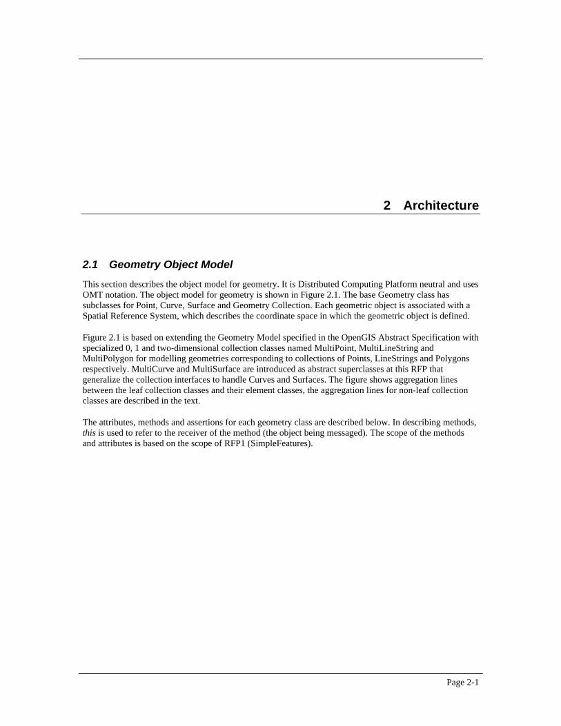
2.1 Geometry Object Model
This section describes the object model for geometry. It is Distributed Computing Platform neutral and usesOMT notation. The object model for geometry is shown in Figure 2.1. The base Geometry class hassubclasses for Point, Curve, Surface and Geometry Collection. Each geometric object is associated with aSpatial Reference System, which describes the coordinate space in which the geometric object is defined.
Figure 2.1 is based on extending the Geometry Model specified in the OpenGIS Abstract Specification withspecialized 0, 1 and two-dimensional collection classes named MultiPoint, MultiLineString andMultiPolygon for modelling geometries corresponding to collections of Points, LineStrings and Polygonsrespectively. MultiCurve and MultiSurface are introduced as abstract superclasses at this RFP thatgeneralize the collection interfaces to handle Curves and Surfaces. The figure shows aggregation linesbetween the leaf collection classes and their element classes, the aggregation lines for non-leaf collectionclasses are described in the text.
The attributes, methods and assertions for each geometry class are described below. In describing methods,this is used to refer to the receiver of the method (the object being messaged). The scope of the methodsand attributes is based on the scope of RFP1 (SimpleFeatures).

OpenGIS Simple Features Specification for SQL, Revision1.1
Page 2-2
MultiPoint
SurfaceCurvePoint
LinearRing
LineString
Line
GeometryCollection
SpatialReferenceSystemGeometry
MultiCurve
MultiLineString
MultiSurface
MultiPolygon
Polygon
1+
1+
1+
1+ 2+
Figure 2.1Geometry Class Hierarchy
2.1.1 Geometry
Geometry is the root class of the hierarchy. Geometry is an abstract (non-instantiable) class.
The instantiable subclasses of Geometry defined in this specification are restricted to 0, 1 and two-dimensional geometric objects that exist in two-dimensional coordinate space (ℜ2).
All instantiable geometry classes described in this specification are defined so that valid instances of ageometry class are topologically closed (i.e. all defined geometries include their boundary).
2.1.1.1 Basic Methods on Geometry
Dimension ( ):Integer—The inherent dimension of this Geometry object, which must be less than or equalto the coordinate dimension. This specification is restricted to geometries in two-dimensional coordinatespace.
GeometryType ( ):String —Returns the name of the instantiable subtype of Geometry of which thisGeometry instance is a member. The name of the instantiable subtype of Geometry is returned as a string.
SRID ( ):Integer—Returns the Spatial Reference System ID for this Geometry.
Envelope( ):Geometry—The minimum bounding box for this Geometry, returned as a Geometry. Thepolygon is defined by the corner points of the bounding box ((MINX, MINY), (MAXX, MINY), (MAXX,MAXY), (MINX, MAXY), (MINX, MINY)).
AsText( ):String —Exports this Geometry to a specific well-known text representation of Geometry.

Chapter 2 Architecture
Page 2-3
AsBinary( ):Binary—Exports this Geometry to a specific well-known binary representation of Geometry.
IsEmpty( ):Integer —Returns 1 (TRUE) if this Geometry is the empty geometry . If true, then thisGeometry represents the empty point set, ∅, for the coordinate space.
IsSimple( ):Integer —Returns 1 (TRUE) if this Geometry has no anomalous geometric points, such as selfintersection or self tangency. The description of each instantiable geometric class will include the specificconditions that cause an instance of that class to be classified as not simple.
Boundary( ):Geometry —Returns the closure of the combinatorial boundary of this Geometry. Thecombinatorial boundary is defined as described in section 3.12.3.2 of [1]. Because the result of this functionis a closure, and hence topologically closed, the resulting boundary can be represented usingrepresentational geometry primitives as discussed in [1], section 3.12.2.
2.1.1.2 Methods for testing Spatial Relations between geometric objects :
The methods in this section are defined and described in more detail following the description of the subtypes of Geometry.
Equals(anotherGeometry:Geometry):Integer — Returns 1 (TRUE) if this Geometry is ‘spatially equal’ toanotherGeometry.
Disjoint(anotherGeometry:Geometry):Integer— Returns 1 (TRUE) if this Geometry is ‘spatially disjoint’from anotherGeometry.
Intersects(anotherGeometry:Geometry):Integer— Returns 1 (TRUE) if this Geometry ‘spatially intersects’anotherGeometry.
Touches(anotherGeometry:Geometry):Integer— Returns 1 (TRUE) if this Geometry ‘spatially touches’anotherGeometry.
Crosses(anotherGeometry:Geometry):Integer— Returns 1 (TRUE) if this Geometry ‘spatially crosses’anotherGeometry.
Within(anotherGeometry:Geometry):Integer — Returns 1 (TRUE) if this Geometry is ‘spatially within’anotherGeometry.
Contains(anotherGeometry:Geometry):Integer — Returns 1 (TRUE) if this Geometry ‘spatially contains’anotherGeometry.
Overlaps(anotherGeometry:Geometry):Integer — Returns 1 (TRUE) if this Geometry ‘spatially overlaps’anotherGeometry.
Relate(anotherGeometry:Geometry, intersectionPatternMatrix:String):Integer— Returns 1 (TRUE) if thisGeometry is spatially related to anotherGeometry, by testing for intersections between the Interior,Boundary and Exterior of the two geometries as specified by the values in the intersectionPatternMatrix.
2.1.1.3 Methods that support Spatial Analysis
Distance(anotherGeometry:Geometry):Double—Returns the shortest distance between any two points inthe two geometries as calculated in the spatial reference system of this Geometry.

OpenGIS Simple Features Specification for SQL, Revision1.1
Page 2-4
Buffer(distance:Double):Geometry—Returns a geometry that represents all points whose distance fromthis Geometry is less than or equal to distance. Calculations are in the Spatial Reference System of thisGeometry.
ConvexHull( ):Geometry—Returns a geometry that represents the convex hull of this Geometry.
Intersection(anotherGeometry:Geometry):Geometry—Returns a geometry that represents the point setintersection of this Geometry with anotherGeometry.
Union(anotherGeometry:Geometry):Geometry—Returns a geometry that represents the point set union ofthis Geometry with anotherGeometry.
Difference(anotherGeometry:Geometry):Geometry—Returns a geometry that represents the point setdifference of this Geometry with anotherGeometry.
SymDifference(anotherGeometry:Geometry):Geometry—Returns a geometry that represents the point setsymmetric difference of this Geometry with anotherGeometry.
2.1.2 Geometry Collection
A GeometryCollection is a geometry that is a collection of 1 or more geometries.
All the elements in a GeometryCollection must be in the same Spatial Reference. This is also the SpatialReference for the GeometryCollection.
GeometryCollection places no other constraints on its elements. Subclasses of GeometryCollection mayrestrict membership based on dimension and may also place other constraints on the degree of spatialoverlap between elements.
2.1.2.1 Methods
NumGeometries( ):Integer—Returns the number of geometries in this GeometryCollection.
GeometryN(N:integer):Geometry—Returns the Nth geometry in this GeometryCollection.
2.1.3 Point
A Point is a 0-dimensional geometry and represents a single location in coordinate space. A Point has a x-coordinate value and a y-coordinate value.
The boundary of a Point is the empty set.
2.1.3.1 Methods
X( ):Double —The x-coordinate value for this Point.
Y( ):Double —The y-coordinate value for this Point.
2.1.4 MultiPoint
A MultiPoint is a 0 dimensional geometric collection. The elements of a MultiPoint are restricted to Points.The points are not connected or ordered.

Chapter 2 Architecture
Page 2-5
A MultiPoint is simple if no two Points in the MultiPoint are equal (have identical coordinate values).
The boundary of a MultiPoint is the empty set.
2.1.5 Curve
A Curve is a one-dimensional geometric object usually stored as a sequence of points, with the subtype ofCurve specifying the form of the interpolation between points. This specification defines only one subclassof Curve, LineString, which uses linear interpolation between points.
Topologically a Curve is a one-dimensional geometric object that is the homeomorphic image of a real,closed, interval D = [a, b] = {x ∈ R a <= x <= b} under a mapping f:[a,b] → ℜ2 as defined in [1],section 3.12.7.2.
A Curve is simple if it does not pass through the same point twice ([1], section 3.12.7.3)
∀ c ∈ Curve, [a, b] = c.Domain,
c.IsSimple ⇔ ( ∀ x1, x2 ∈ (a, b] x1 ≠ x2 ⇒ f(x1) ≠ f (x2)) ∧ (∀ x1, x2 ∈ [a, b) x1 ≠ x2 ⇒ f(x1) ≠ f(x2))
A Curve is closed if its start point is equal to its end point. ([1], section 3.12.7.3)
The boundary of a closed Curve is empty.
A Curve that is simple and closed is a Ring.
The boundary of a non-closed Curve consists of its two end points. ([1], section 3.12.3.2).
A Curve is defined as topologically closed.
2.1.5.1 Methods
Length( ):Double—The length of this Curve in its associated spatial reference.
StartPoint( ):Point—The start point of this Curve.
EndPoint( ):Point—The end point of this Curve.
IsClosed( ):Integer—Returns 1 (TRUE) if this Curve is closed (StartPoint ( ) = EndPoint ( )).
IsRing( ):Integer—Returns 1 (TRUE) if this Curve is closed (StartPoint ( ) = EndPoint ( )) and this Curveis simple (does not pass through the same point more than once).
2.1.6 LineString, Line, LinearRing
A LineString is a Curve with linear interpolation between points. Each consecutive pair of points defines aline segment.
A Line is a LineString with exactly 2 points.
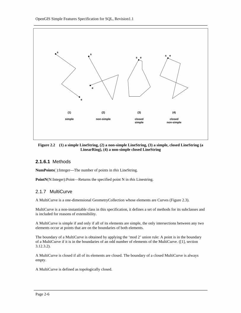
A LinearRing is a LineString that is both closed and simple. The curve in Figure 2.2—(3) is a closedLineString that is a LinearRing. The curve in Figure 2.2—(4) is a closed LineString that is not aLinearRing.
OpenGIS Simple Features Specification for SQL, Revision1.1
Page 2-6
s es e
s
e
s
e
(1)
simple
(2)
non-simple
(3)
closedsimple
(4)
closednon-simple
Figure 2.2(1) a simple LineString, (2) a non-simple LineString, (3) a simple, closed LineString (aLinearRing), (4) a non-simple closed LineString
2.1.6.1 Methods
NumPoints( ):Integer—The number of points in this LineString.
PointN(N:Integer):Point—Returns the specified point N in this Linestring.
2.1.7 MultiCurve
A MultiCurve is a one-dimensional GeometryCollection whose elements are Curves (Figure 2.3).
MultiCurve is a non-instantiable class in this specification, it defines a set of methods for its subclasses andis included for reasons of extensibility.
A MultiCurve is simple if and only if all of its elements are simple, the only intersections between any twoelements occur at points that are on the boundaries of both elements.
The boundary of a MultiCurve is obtained by applying the ‘mod 2’ union rule: A point is in the boundaryof a MultiCurve if it is in the boundaries of an odd number of elements of the MultiCurve. ([1], section3.12.3.2).
A MultiCurve is closed if all of its elements are closed. The boundary of a closed MultiCurve is alwaysempty.
A MultiCurve is defined as topologically closed.

Chapter 2 Architecture
Page 2-7
2.1.7.1 Methods
IsClosed( ):Integer—Returns 1 (TRUE) if this MultiCurve is closed (StartPoint ( ) = EndPoint ( ) for eachcurve in this MultiCurve)
Length( ):Double—The Length of this MultiCurve which is equal to the sum of the lengths of the elementCurves.
2.1.8 MultiLineString
A MultiLineString is a MultiCurve whose elements are LineStrings.
s2 e2
s1
e1
(2)
non-simple
(1)
simple
s
s2e1
e2
(3)
closednon-simple
s2 e2
s1
e1
Figure 2.3(1) a simple MultiLineString, (2) a non-simple MultiLineString with 2 elements, (3) anon-simple, closed MultiLineString with 2 elements
The boundaries for the MultiLineStrings in Figure 2.3 are (1){s1, e2}, (2){s1, e1}, (3)∅
2.1.9 Surface
A Surface is a two-dimensional geometric object.
The OpenGIS Abstract Specification defines a simple Surface as consisting of a single ‘patch’ that isassociated with one ‘exterior boundary’ and 0 or more ‘interior’ boundaries. Simple surfaces in three-dimensional space are isomorphic to planar surfaces. Polyhedral surfaces are formed by ‘stitching’ togethersimple surfaces along their boundaries, polyhedral surfaces in three-dimensional space may not be planar asa whole ([1], sections 3.12.9.1, 3.12.9.3).
The boundary of a simple Surface is the set of closed curves corresponding to its ‘exterior’ and ‘interiorboundaries. ([1], section 3.12.9.4).
OpenGIS Simple Features Specification for SQL, Revision1.1
Page 2-8
The only instantiable subclass of Surface defined in this specification, Polygon, is a simple Surface that isplanar.
2.1.9.1 Methods
Area( ):Double—The area of this Surface, as measured in the spatial reference system of this Surface.
Centroid( ):Point—The mathematical centroid for this Surface as a Point. The result is not guaranteed tobe on this Surface.
PointOnSurface( ):Point—A point guaranteed to be on this Surface.
2.1.10 Polygon
A Polygon is a planar Surface, defined by 1 exterior boundary and 0 or more interior boundaries. Eachinterior boundary defines a hole in the Polygon.
The assertions for polygons (the rules that define valid polygons) are:
1. Polygons are topologically closed.
2. The boundary of a Polygon consists of a set of LinearRings that make up its exterior and interiorboundaries.
3. No two rings in the boundary cross, the rings in the boundary of a Polygon may intersect at a Point butonly as a tangent :
∀ P ∈ Polygon, ∀ c1, c2 ∈ P.Boundary(), c1 ≠ c2, ∀ p, q ∈ Point, p, q ∈ c1, p ≠ q, [ p ∈ c2 ⇒ q ∉ c2]
4. A Polygon may not have cut lines, spikes or punctures:
∀ P ∈ Polygon, P = Closure(Interior(P))
5. The Interior of every Polygon is a connected point set.
6. The Exterior of a Polygon with 1 or more holes is not connected. Each hole defines a connectedcomponent of the Exterior.
In the above assertions, Interior, Closure and Exterior have the standard topological definitions. Thecombination of 1 and 3 make a Polygon a Regular Closed point set.
Polygons are simple geometries.
Figure 2.4 shows some examples of Polygons. Figure 2.5 shows some examples of geometric objects thatviolate the above assertions and are not representable as single instances of Polygon. The objects shown inFigure 2.5—(1) and 2.5—(4) can be represented as 2 separate Polygons.

Chapter 2 Architecture
Page 2-9
(1) (2) (3)
Figure 2.4Examples of Polygons with 1, 2 and 3 rings respectively.
(1) (2) (3) (4)
Figure 2.5Examples of objects not representable as a single instance of Polygon. (1) and (4) can berepresented as 2 separate Polygons.
OpenGIS Simple Features Specification for SQL, Revision1.1
Page 2-10
2.1.10.1 Methods
ExteriorRing( ):LineString—Returns the exterior ring of this Polygon.
NumInteriorRing( ):Integer—Returns the number of interior rings in this Polygon.
InteriorRingN(N:Integer):LineString—Returns the Nth interior ring for this Polygon as a LineString.
2.1.11 MultiSurface
A MultiSurface is a two-dimensional geometric collection whose elements are surfaces. The interiors ofany two surfaces in a MultiSurface may not intersect. The boundaries of any two elements in aMultiSurface may intersect at most at a finite number of points.
MultiSurface is a non-instantiable class in this specification, it defines a set of methods for its subclassesand is included for reasons of extensibility. The instantiable subclass of MultiSurface is MultiPolygon,corresponding to a collection of Polygons.
2.1.11.1 Methods
Area( ):Double—The area of this MultiSurface, as measured in the spatial reference system of thisMultiSurface.
Centroid( ):Point—The mathematical centroid for this MultiSurface. The result is not guaranteed to be onthis MultiSurface.
PointOnSurface( ):Point—A Point guaranteed to be on this MultiSurface.
2.1.12 MultiPolygon
A MultiPolygon is a MultiSurface whose elements are Polygons..
The assertions for MultiPolygons are :
1. The interiors of 2 Polygons that are elements of a MultiPolygon may not intersect.
∀ M ∈ MultiPolygon, ∀ Pi, Pj ∈ M.Geometries(), i≠j, Interior(Pi) ∩ Interior(Pj) = ∅
2. The Boundaries of any 2 Polygons that are elements of a MultiPolygon may not ‘cross’ and may touchat only a finite number of points. (Note that crossing is prevented by assertion 1 above).
∀ M ∈ MultiPolygon, ∀ Pi, Pj ∈ M.Geometries(), ∀ ci ∈ Pi.Boundaries(), cj ∈ Pj.Boundaries()ci ∩ cj = {p1, ….., pk | pi ∈ Point, 1 <= i <= k}
3. A MultiPolygon is defined as topologically closed.
4. A MultiPolygon may not have cut lines, spikes or punctures, a MultiPolygon is a Regular, Closed pointset:
∀ M ∈ MultiPolygon, M = Closure(Interior(M))
5. The interior of a MultiPolygon with more than 1 Polygon is not connected, the number of connectedcomponents of the interior of a MultiPolygon is equal to the number of Polygons in the MultiPolygon.
Chapter 2 Architecture
Page 2-11
The boundary of a MultiPolygon is a set of closed curves (LineStrings) corresponding to the boundaries ofits element Polygons. Each Curve in the boundary of the MultiPolygon is in the boundary of exactly 1element Polygon, and every Curve in the boundary of an element Polygon is in the boundary of theMultiPolygon.
The reader is referred to work by Worboys, et. al (7, 8) and Clementini, et. al (5, 6) for work on thedefinition and specification of MultiPolygons.
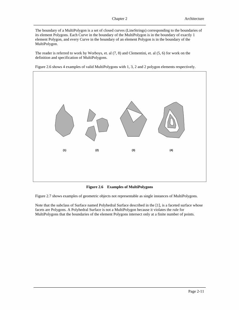
Figure 2.6 shows 4 examples of valid MultiPolygons with 1, 3, 2 and 2 polygon elements respectively.
(3)(2)(1) (4)
Figure 2.6Examples of MultiPolygons
Figure 2.7 shows examples of geometric objects not representable as single instances of MultiPolygons.
Note that the subclass of Surface named Polyhedral Surface described in the [1], is a faceted surface whosefacets are Polygons. A Polyhedral Surface is not a MultiPolygon because it violates the rule forMultiPolygons that the boundaries of the element Polygons intersect only at a finite number of points.

OpenGIS Simple Features Specification for SQL, Revision1.1
Page 2-12
(1) (2) (3)
Figure 2.7Geometric objects not representable as a single instance of a MultiPolygon.
2.1.13 Relational Operators
This section provides a more detailed specification of the relational operators on geometries.
2.1.13.1 Background
The Relational Operators are Boolean methods that are used to test for the existence of a specifiedtopological spatial relationship between two geometries. Topological spatial relationships between twogeometric objects have been a topic of extensive study in the literature [4,5,6,7,8,9,10]. The basic approachto comparing two geometries is to make pair-wise tests of the intersections between the Interiors,Boundaries and Exteriors of the two geometries and to classify the relationship between the two geometriesbased on the entries in the resulting ‘intersection’ matrix.
The concepts of Interior, Boundary and Exterior are well defined in general topology. For a review of theseconcepts the user is referred to Egenhofer, et al [4]. These concepts can be applied in defining spatialrelationships between two-dimensional objects in two-dimensional space (ℜ2). In order to apply theconcepts of Interior, Boundary and Exterior to 1 and 0 dimensional objects in ℜ2, a combinatorial topologyapproach must be applied. ([1], section. 3.12.3.2). This approach is based on the accepted definitions of theboundaries, interiors and exteriors for simplicial complexes [12] and yields the following results:
The boundary of a geometry is a set of geometries of the next lower dimension. The boundary of a Point ora MultiPoint is the empty set. The boundary of a non-closed Curve consists of its two end Points, theboundary of a closed Curve is empty. The boundary of a MultiCurve consists of those Points that are in theboundaries of an odd number of its element Curves. The boundary of a Polygon consists of its set of Rings.The boundary of a MultiPolygon consists of the set of Rings of its Polygons. The boundary of an arbitrarycollection of geometries whose interiors are disjoint consists of geometries drawn from the boundaries ofthe element geometries by application of the ‘mod 2’ union rule ([1], section 3.12.3.2).

Chapter 2 Architecture
Page 2-13
The domain of geometric objects considered is those that are topologically closed. The interior of ageometry consists of those points that are left when the boundary points are removed. The exterior of ageometry consists of points not in the interior or boundary.
Studies on the relationships between two geometries both of maximal dimension in ℜ1 and ℜ2 consideredpair-wise intersections between the Interior and Boundary sets and led to the definition of a 4 IntersectionModel [8]. The model was extended to consider the exterior of the input geometries, resulting in a nineintersection model [11] and further extended to include information on the dimension of the results of thepair-wise intersections resulting in a dimensionally extended nine intersection model [5]. These extensionsallow the model to express spatial relationships between points, lines and areas, including areas with holesand multi component lines and areas [6].
2.1.13.2 The Dimensionally Extended Nine-Intersection Model
Given a geometry a, let I(a), B(a) and E(a) represent the Interior, Boundary and Exterior of a respectively.The intersection of any two of I(a), B(a) and E(a) can result in a set of geometries, x, of mixed dimension.For example, the intersection of the boundaries of two polygons may consist of a point and a line. Letdim(x) return the maximum dimension (-1, 0, 1, or 2) of the geometries in x, with a numeric value of -1corresponding to dim(∅). A dimensionally extended nine-intersection matrix (DE-9IM) then has the form:
Interior Boundary Exterior
Interior dim(I(a)∩I(b)) dim(I(a)∩B(b)) dim(I(a)∩E(b))
Boundary dim(B(a)∩I(b)) dim(B(a)∩B(b)) dim(B(a)∩E(b))
Exterior dim(E(a)∩I(b)) dim(E(a)∩B(b)) dim(E(a)∩E(b))
Table 2.1The DE-9IM
For regular, topologically closed input geometries, computing the dimension of the intersection of theInterior, Boundary and Exterior sets does not have as a prerequisite the explicit computation andrepresentation of these sets. For example to compute if the interiors of two regular closed polygonsintersect, and to ascertain the dimension of this intersection, it is not necessary to explicitly represent theinterior of the two polygons (which are topologically open sets) as separate geometries. In most cases thedimension of the intersection value at a cell is highly constrained given the type of the two geometries. Forexample, in the Line-Area case the only possible values for the Interior-Interior cell are drawn from {-1, 1}and in the Area-Area case the only possible values for the Interior-Interior cell are drawn from {-1, 2}. Insuch cases no work beyond detecting the intersection is required.
Figure 2.8 shows an example DE-9IM for the case where a and b are two polygons that overlap.

OpenGIS Simple Features Specification for SQL, Revision1.1
Page 2-14
Interior Boundary Exterior
Interior 2 1 2
Boundary 1 0 1
Exterior 2 1 2
(a) (b)
Figure 2.8An example instance and its DE-9IM
A spatial relationship predicate can be formulated on two geometries that takes as input a pattern matrixrepresenting the set of acceptable values for the DE-9IM for the two geometries. If the spatial relationshipbetween the two geometries corresponds to one of the acceptable values as represented by the patternmatrix, then the predicate returns TRUE.
The pattern matrix consists of a set of 9 pattern-values, one for each cell in the matrix. The possible pattern-values p are {T, F, *, 0, 1, 2} and their meanings for any cell where x is the intersection set for the cell areas follows:
p = T => dim(x) ∈{0, 1, 2}, i.e. x ≠∅
p = F => dim(x) = -1, i.e. x = ∅
p = * => dim(x) ∈ {-1, 0, 1, 2}, i.e. Don’t Care
p = 0 => dim(x) = 0
p = 1 => dim(x) = 1
p = 2 => dim(x) = 2
The pattern matrix can be represented as an array or list of nine characters in row major order. As anexample the following code fragment could be used to test for ‘Overlap’ between two areas:
char * overlapMatrix = ‘T*T***T**’;
Geometry* a, b;
Boolean b = a->Relate(b, overlapMatrix);
Chapter 2 Architecture
Page 2-15
2.1.13.3 Named Spatial Relationship predicates based on the DE-9IM
The Relate predicate based on the pattern matrix has the advantage that clients can test for a large numberof spatial relationships and fine tune the particular relationship being tested. It has the disadvantage that itis a lower level building block and does not have a corresponding natural language equivalent. Users of theproposed system include IT developers using the COM API from a language such as Visual Basic, andinteractive SQL users who may wish, for example, to select all features ‘spatially within’ a query polygon,in addition to more spatially ‘sophisticated’ GIS developers.
To address the needs of such users a set of named spatial relationship predicates have been defined in [5,6]for the DE-9IM. The five predicates are named Disjoint, Touches, Crosses, Within and Overlaps. Thedefinition of these predicates [5,6] is given below. In these definitions the term P is used to refer to 0dimensional geometries (Points and MultiPoints), L is used to refer to one-dimensional geometries(LineStrings and MultiLineStrings) and A is used to refer to two-dimensional geometries (Polygons andMultiPolygons).
Disjoint
Given two (topologically closed) geometries a and b,
a.Disjoint(b) ⇔ a ∩ b = ∅
Expressed in terms of the DE-9IM:
a.Disjoint(b) ⇔ (I(a)∩I(b) = ∅) ∧ (I(a) ∩ B(b) = ∅) ∧ (B(a) ∩I(b) = ∅) ∧ (B(a) ∩ B(b) = ∅)⇔ a.Relate(b, ‘FF*FF****’)
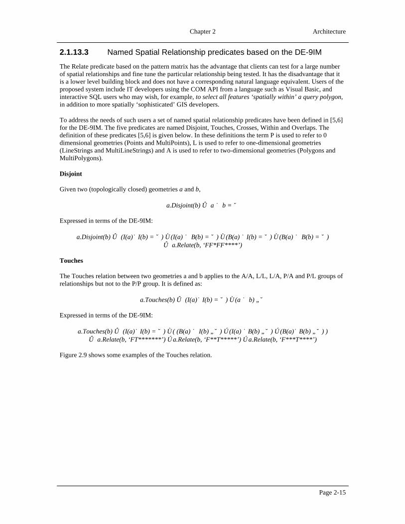
Touches
The Touches relation between two geometries a and b applies to the A/A, L/L, L/A, P/A and P/L groups ofrelationships but not to the P/P group. It is defined as:
a.Touches(b) ⇔ (I(a)∩I(b) = ∅) ∧ (a ∩ b) ≠∅
Expressed in terms of the DE-9IM:
a.Touches(b) ⇔ (I(a)∩I(b) = ∅) ∧ ( (B(a) ∩ I(b) ≠∅) ∨ (I(a) ∩B(b) ≠∅) ∨ (B(a)∩B(b) ≠∅) )⇔ a.Relate(b, ‘FT*******’) ∨ a.Relate(b, ‘F**T*****’) ∨ a.Relate(b, ‘F***T****’)
Figure 2.9 shows some examples of the Touches relation.

OpenGIS Simple Features Specification for SQL, Revision1.1
Page 2-16
Polygon/Polygon
Polygon/LineString
Polygon/Point
LineString/Point
LineString/LineString
(a) (b)
12
1 2(a) (b)
Figure 2.9Examples of the Touches relationship
Crosses
The Crosses relation applies to P/L, P/A, L/L and L/A situations. It is defined as:
a.Crosses(b) ⇔ (dim(I(a) ∩ I(b)) < max(dim(I(a)), dim(I(b)))) ∧ (a ∩ b ≠a ) ∧ (a ∩ b ≠b)
Expressed in terms of the DE-9IM:
Case a ∈ P, b ∈ L or Case a ∈ P, b ∈ A or Case a ∈ L, b ∈ A:
a.Crosses(b) ⇔ (I(a) ∩ I(b) ≠∅) ∧ (I(a) ∩ E(b) ≠∅) ⇔ a.Relate(b, ‘T*T******’)
Case a ∈ L, b ∈ L:
a.Crosses(b) ⇔ dim(I(a)∩I(b)) = 0 ⇔ a.Relate(b, ‘0********’);
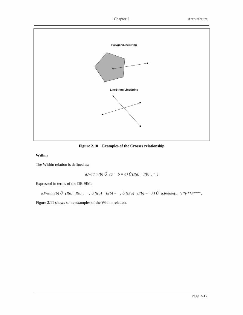
Figure 2.10 shows some examples of the Crosses relation.
Chapter 2 Architecture
Page 2-17
Polygon/LineString
LineString/LineString
Figure 2.10Examples of the Crosses relationship
Within
The Within relation is defined as:
a.Within(b) ⇔ (a ∩ b = a) ∧ (I(a) ∩I(b) ≠ ∅)
Expressed in terms of the DE-9IM:
a.Within(b) ⇔ (I(a)∩I(b) ≠ ∅) ∧ (I(a) ∩E(b) =∅) ∧ (B(a)∩E(b) =∅) ) ⇔ a.Relate(b, ‘T*F**F***’)
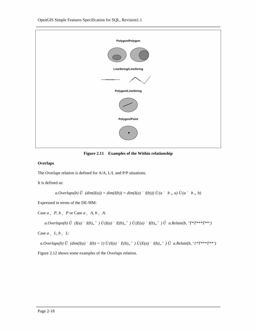
Figure 2.11 shows some examples of the Within relation.
OpenGIS Simple Features Specification for SQL, Revision1.1
Page 2-18
Polygon/Polygon
Polygon/LineString
Polygon/Point
LineString/LineString
Figure 2.11Examples of the Within relationship
Overlaps
The Overlaps relation is defined for A/A, L/L and P/P situations.
It is defined as:
a.Overlaps(b) ⇔ (dim(I(a)) = dim(I(b)) = dim(I(a) ∩I(b))) ∧ (a ∩ b ≠ a) ∧ (a ∩ b ≠ b)
Expressed in terms of the DE-9IM:
Case a ∈ P, b ∈ P or Case a ∈ A, b ∈ A:
a.Overlaps(b) ⇔ (I(a) ∩I(b)≠∅) ∧ (I(a) ∩E(b)≠∅) ∧ (E(a) ∩I(b)≠∅) ⇔ a.Relate(b, ‘T*T***T**’)
Case a ∈ L, b ∈ L:
a.Overlaps(b) ⇔ (dim(I(a) ∩I(b) = 1) ∧ (I(a) ∩E(b)≠∅) ∧ (E(a) ∩I(b)≠∅) ⇔ a.Relate(b, ‘1*T***T**’)
Figure 2.12 shows some examples of the Overlaps relation.

Chapter 2 Architecture
Page 2-19
Polygon/Polygon
LineString/LineString
s1
s2e1
e2
Figure 2.12Examples of the Overlaps relationship
The following additional named predicates are also defined for user convenience:
Contains
a.Contains(b) ⇔ b.Within(a)
Intersects
a.Intersects(b) ⇔ ! a.Disjoint(b)
Based on the above operators the following methods are defined on Geometry:
Equals(anotherGeometry:Geometry):Integer—Returns 1 (TRUE) if this Geometry is ‘spatially equal’ toanotherGeometry.
Disjoint(anotherGeometry:Geometry):Integer— Returns 1 (TRUE) if this Geometry is ‘spatially disjoint’from anotherGeometry.
Intersects(anotherGeometry:Geometry):Integer— Returns 1 (TRUE) if this Geometry ‘spatially intersects’anotherGeometry.
Touches(anotherGeometry:Geometry):Integer— Returns 1 (TRUE) if this Geometry ‘spatially touches’anotherGeometry.
Crosses(anotherGeometry:Geometry):Integer— Returns 1 (TRUE) if this Geometry ‘spatially crosses’anotherGeometry.

OpenGIS Simple Features Specification for SQL, Revision1.1
Page 2-20
Within(anotherGeometry:Geometry):Integer— Returns 1 (TRUE) if this Geometry is ‘spatially within’anotherGeometry.
Contains(anotherGeometry:Geometry):Integer— Returns 1 (TRUE) if this Geometry ‘spatially contains’anotherGeometry.
Overlaps(anotherGeometry:Geometry):Integer— Returns 1 (TRUE) if this Geometry ‘spatially overlaps’anotherGeometry.
Relate(anotherGeometry:Geometry, intersectionPatternMatrix:String):Integer— Returns 1 (TRUE) if thisGeometry is spatially related to anotherGeometry, by testing for intersections between the Interior,Boundary and Exterior of the two geometries.
2.2 Architecture—SQL92 Implementation of Feature Tables
A SQL92 implementation of OpenGIS simple geospatial feature collections defines a schema for storage offeature table, geometry and spatial reference system information. The SQL92 implementation does notdefine SQL functions for access, maintenance, or indexing of geometry, as these functions cannot beuniformly implemented across database systems using the SQL92 standard.
The figure below describes the database schema necessary to support the OpenGIS simple feature datamodel. A feature table or view corresponds to an OpenGIS feature class. Each feature view contains somenumber of features represented as rows in the view. Each feature contains some number of geometricattribute values represented as columns in the feature view. Each geometric column in a feature view isassociated with a particular geometric view or table that contains geometry instances in a single spatialreference system. The correspondence between the feature instances and the geometry instances shall beaccomplished through a foreign key that is stored in the geometry column of the feature table. This foreignkey references the GID primary key of the geometry table.
GEOMETRY_COLUMNS
F_TABLE_CATALOGF_TABLE_SCHEMA
F_TABLE_NAME
F_GEOMETRY_COLUMN
G_TABLE_CATALOG
G_TABLE_SCHEMA
G_TABLE_NAMESTORAGE_TYPE
GEOMETRY_TYPE
COORD_DIMENSION
MAX_PPR
SRID
SPATIAL_REFERENCE_SYSTEMS
SRID
AUTH_NAME
AUTH_SRID
SRTEXT
GEOMETRY_COLUMNS
GID
ESEQ
ETYPE
SEQ
X1Y1
……
X<MAX_PPR>
Y<MAX_PPR>
GEOMETRY_COLUMNS
GID
XMIN
YMIN
XMAX
YMAXWKB_GEOMETRY
Feature Table/View
<Attributes>GID (Geometry Column)
<Attributes>
or
Figure 2.13Schema for feature tables under SQL92
Chapter 2 Architecture
Page 2-21
Depending upon the type of storage specified by the geometry metadata, Geometry instances shall bestored as either arrays of coordinate values or as binary values using an OpenGIS defined Well-KnownBinary Representation for Geometry. In the former case, SQL numeric types are used for the coordinatesand client side functions are needed to build OpenGIS geometry objects from the retrieved coordinatenumeric values. In the latter case clients may feed the retrieved well-known binary representation directlyinto the Geometry factory of the client side computing environment (e.g., an OLE/COM or CORBAgeometry factory) or choose to access the individual coordinate values by unpacking the well-knownrepresentation.
2.2.1 Feature Table Metadata Views
A feature table is any table having 1 or more foreign key reference to a geometry table or view. The set offeature tables in a database can be determined using the above rule from the TABLES,REFERENTIAL_CONSTRAINTS and COLUMNS metadata views in the SQL92INFORMATION_SCHEMA. The set of feature tables can also be determined by issuing a query over theGEOMETRY_COLUMNS metadata view described below.
2.2.2 Geometry Columns Metadata Views
Each geometry column will be represented as a row in the standard COLUMNS metadata view in theSQL92 INFORMATION_SCHEMA. Spatial Reference System Identity is however not a standard part ofthe SQL92 INFORMATION_SCHEMA. To represent this information we introduce an additionalmetadata view named GEOMETRY_COLUMNS.
The GEOMETRY_COLUMNS table or view consists of a row for each geometry column in the database.The data stored for each geometry column includes:
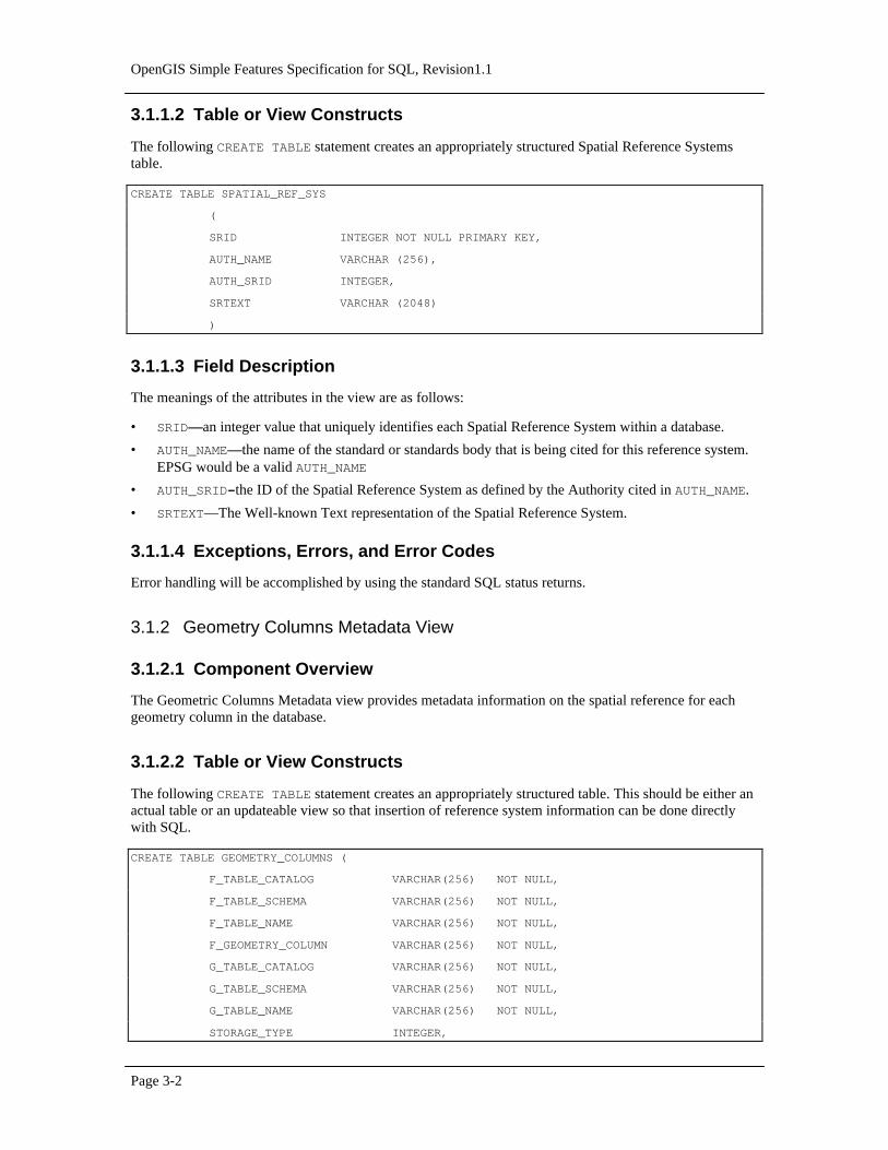
• the identity of the feature table of which it is a member,
• the spatial reference system ID,
• the type of geometry for the column,
• the coordinate dimension for the column,
• the identity of the geometry table that stores its instances, and
• the information necessary to navigate the geometry tables in the case of normalized geometry storage.
2.2.3 Spatial Reference System Information Views
Every geometry column is associated with a Spatial Reference System. The Spatial Reference Systemidentifies the coordinate system for all geometries stored in the column, and gives meaning to the numericcoordinate values for any geometry instance stored in the column. Examples of commonly used SpatialReference Systems include ‘Latitude Longitude’, and ‘UTM Zone 10’.
The SPATIAL_REFERENCE_SYSTEMS table stores information on each Spatial Reference System inthe database. The columns of this table are the Spatial Reference System Identifier (SRID), the SpatialReference System Authority Name (AUTH_NAME) , the Authority Specific Spatial Reference SystemIdentifier (AUTH_SRID) and the Well-known Text description of the Spatial Reference System(SRTEXT). The Spatial Reference System Identifier (SRID) constitutes a unique integer key for a SpatialReference System within a database.
OpenGIS Simple Features Specification for SQL, Revision1.1
Page 2-22
Interoperability between clients is achieved via the SRTEXT column which stores the Well-known Textrepresentation for a Spatial Reference System as described in Section 3.4.
2.2.4 Feature Tables and Views
A Feature is an object with geometric attributes [1]. Features are stored as rows in tables, each geometricattribute is a foreign key reference to a geometry table or view. Relationships between Features are definedas FOREIGN KEY references between feature tables.
2.2.5 Geometry and Geometric Element Views
There are two implementations for storing geometries in SQL92: using a normalized geometry SQL92schema, and using a binary geometry SQL92 schema. The binary geometry schema uses the Well-knownBinary Representation for Geometry (WKBGeometry) described in section 3.3. The normalized geometryimplementation defines fixed width SQL92 tables such as the example in Figure 2.14. Each primitiveelement in the geometry is distributed over some number of adjacent rows in the table ordered by asequence number (SEQ), and identified by a primitive type (ETYPE). Each geometry identified by a key(GID), consists of a collection of elements numbered by an element sequence (ESEQ).
The rules for geometric entity representation in the normalized SQL92 schema are defined as follows:
• ETYPE designates the geometry type.
• Geometries may have multiple elements. The ESEQ value identifies the individual elements.
• An element may be built up from multiple parts (rows). The rows and their proper sequence areidentified by the SEQ value.
• Polygons may contain holes, as described in the geometry object model.
• Polygon rings must close when assembled from an ordered list of parts. The SEQ value designates thepart order.
• Coordinate pairs that are not used must be set to Nil in complete sets (both X and Y). This is the onlyway to identify the end of list of coordinates.
• For geometries that continue onto an additional row (as defined by an constant element sequencenumber or ESEQ) the last point of one row is equal to the first point of the next.
• There is no limit on the number of elements in the geometry, or the number of rows in a element.

Chapter 2 Architecture
Page 2-23
GID ESEQ ETYPE SEQ X0 Y0 X1 Y1 X2 Y2 X3 Y3 X4 Y4
1 1 3 1 0 0 0 30 30 30 30 0 0 0
1 2 3 1 10 10 10 20 20 20 20 10 10 10
2 1 3 1 30 0 30 30 60 30 60 0 30 0
2 2 3 1 40 5 40 20 45 20 45 15 50 15
2 2 3 2 50 15 50 5 40 5 Nil Nil Nil Nil
3 1 3 1 0 30 0 60 30 60 30 30 0 30
4 1 3 1 30 30 30 60 60 60 60 30 30 30
(40,5)
(40,20) (45,20)
(45,15)
(50,15)
(50,5)
SEQ 2
SEQ 1
ESEQ 2ESEQ 1
GID 1 GID 2
GID 3 GID 4
(0,0)
(0,30)
(0,60)
(60,0)
(60,30)
(60,60)
(30,0)
(30,60)
Figure 2.14Example of geometry table for Polygon Geometry using SQL
The binary geometry implementation is illustrated in Table 2.2, and uses the same GID as a key, but storesthe geometry using the Well-known Binary Representation for Geometry (WKBGeometry) described insection 3.3. The geometry table includes the minimum bounding rectangle for the geometry as well as theWKBGeometry for the geometry. This permits construction of spatial indexes without accessing the actualgeometry structure, if desired.
GID XMIN YMIN XMAX YMAX GEOMETRY
1 0 0 30 30 < WKBGeometry>
2 30 0 60 30 < WKBGeometry >
3 0 30 30 60 < WKBGeometry >
4 30 30 60 60 < WKBGeometry >
Table 2.2Example of geometry table for above Polygon Geometry using the Well-known BinaryRepresentation for Geometry.
2.2.6 Notes on SQL92 data types
There are various ways to store the same values in a relational database. For example, there are usuallyseveral ways to store numbers. In this specification, the use of a storage alternative is not meant to bebinding. Since the storage type of any column is available in the data dictionary, and such casting operatorsbetween similar types are available, any particular implementation may use alternative storage formats aslong as casting operations would not lead to difficulties.

OpenGIS Simple Features Specification for SQL, Revision1.1
Page 2-24
2.2.7 Notes on ODBC Access to Geometry Values stored in Binary form.
ODBC provides standard mechanisms to bind character, numeric and binary data values.
This section describes the process of retrieving geometry values for the case where the binary storagealternative is chosen.
The WKB_GEOMETRY column in the geometry table for a geometry column surfaces in ODBC as one ofthe ODBC binary SQL data types (SQL_BINARY, SQL_VARBINARY, or SQL_LONGVARBINARY).An application binds to this column using the ODBC 2.0 C datatype SQL_C_BINARY.
For example, the application would use the SQL_C_BINARY value for the fCType parameter ofSQLBindCol (or SQLGetData) in order to describe the application data buffer that will receive the fetchedGeometry data value. Similarly, a dynamic parameter whose value is a Geometry would be described usingthe SQL_C_BINARY value for the fCType parameter of SQLBindParameter.
This allows binary values to be both retrieved from and inserted into the geometry tables.
2.3 Architecture—SQL92 with Geometry Types Implementation of FeatureTables
2.3.1 Feature Table Metadata Views
A feature table is any table having one or more columns whose SQL Type is drawn from the set ofGeometry SQL Types defined in section 3.2.3. The set of feature tables in a database can be determinedfrom the TABLES and COLUMNS metadata views in the SQL92 INFORMATION_SCHEMA. The set offeature tables can also be determined by querying the GEOMETRY_COLUMNS metadata view asdescribed below.
2.3.2 Geometry Columns Metadata Views
Each geometry column will be represented as a row in the standard COLUMNS metadata view in theSQL92 INFORMATION_SCHEMA. Spatial Reference System Identity is however not a standard part ofthe SQL92 INFORMATION_SCHEMA. To represent this information we introduce an additionalmetadata view named GEOMETRY_COLUMNS.
The GEOMETRY_COLUMNS table or view consists of a row for each geometry column in the database.The data stored for each geometry column includes the identity of the feature table of which it is a member,the spatial reference system ID, the type of geometry for the column, and the coordinate dimension.
The columns in the GEOMETRY_COLUMNS metadata view for the SQL92 with Geometry Typesenvironment are a subset of the columns in the GEOMETRY_COLUMNS view defined for the SQL92environment.
2.3.3 Spatial Reference System Information Views
Every geometry column is associated with a Spatial Reference System. The Spatial Reference Systemidentifies the coordinate system for all geometries stored in the column, and gives meaning to the numericcoordinate values for any geometry instance stored in the column. Examples of commonly used SpatialReference Systems include ‘Latitude Longitude’, and ‘UTM Zone 10’.
The SPATIAL_REFERENCE_SYSTEMS table stores information on each Spatial Reference System inthe database. The columns of this table are the Spatial Reference System Identifier (SRID), the Spatial
Chapter 2 Architecture
Page 2-25
Reference System Authority Name (AUTH_NAME) , the Authority Specific Spatial Reference SystemIdentifier (AUTH_SRID) and the Well-known Text description of the Spatial Reference System(SRTEXT). The Spatial Reference System Identifier (SRID) constitutes a unique integer key for a SpatialReference System within a database.
Interoperability between clients is achieved via the SRTEXT column which stores the Well-known Textrepresentation for a Spatial Reference System as described in section 3.4.
The Spatial Reference System Information View for the SQL92 with Geometry Types implementation isidentical to the Spatial Reference System Information View for the SQL92 implementation.
2.3.4 Feature Tables and Views
A Feature is an object with geometric attributes [1]. Feature are stored in tables, each geometric attribute isstored in a geometric column whose type is drawn from the set of SQL Geometry Types described insection 3.2.3. Relationships between Features are defined as FOREIGN KEY references between featuretables.
2.3.5 Background Information on SQL Abstract Data Types
The term Abstract Data Type (ADT) refers to a data type that extends the SQL type system.
ADT types can be used to define the column types for tables, this allows values stored in the columns of atable to be instances of ADTs.
SQL functions may be declared to take ADT values as arguments, and return ADT values as results.
An ADT may be defined as a subtype of another ADT, referred to as its supertype. This allows an instanceof the subtype to be stored in any column where an instance of the supertype is expected and allows aninstance of the subtype to be used as an argument or return value in any SQL function that is declared touse the super type as an argument or return value.
The above definition of ADTs is value based, and value based ADTs with the above properties are definedas part of the current draft SQL3 standard.
SQL implementations that support Abstract Data Types may also support the concept of References toAbstract Data Type instances that are stored as rows in a table whose type corresponds to the type of theAbstract Data Type. The terms RowType and Reference to RowType are also used to describe such types.The above concepts of Types that support tables whose rows are instances of the Type and that supportReferences to Type instances are also part of the current draft SQL3 standard.
This specification allows Geometry Types to be implemented as either pure value based Types or as Typesthat support persistent References.
2.3.6 Scope of this OpenGIS Geometry Types specification
This specification does not attempt to standardize and does not depend upon any part of the mechanism bywhich Types are added and maintained in the SQL environment including
• The syntax and functionality provided for defining types
• The syntax and functionality provided for defining SQL functions
• The physical storage of type instances in the database

OpenGIS Simple Features Specification for SQL, Revision1.1
Page 2-26
• The specific terminology used to refer to types, for example, ADT.
This specification does standardize:
• The names and geometric definitions of the OpenGIS SQL Types for Geometry.
• The names, signatures and geometric definitions of the OpenGIS SQL Functions for Geometry.
The types for geometry are defined in black box terms, i.e. all access to information about a geometry typeinstance is through SQL functions. No attempt is made to distinguish functions that may access typeinstance attributes (such as the dimension of a geometry instance) from functions that may compute valuesgiven a type instance (such as the centroid of a polygon). In particular, a SQL3 implementation of thisspecification would be free to nominate any set of functions as observer methods on attributes of anAbstract Data Type in SQL3 as long as the signatures of the SQL functions described in this specificationare preserved.
This specification does not place any requirements on when or how or who defines the Geometry Types. Inparticular, a compliant system may be shipped to the database user with the set of Geometry Types andFunctions already built into the RDBMS server, or with the set of Geometry Types and Functions suppliedto the database user as a dynamically loaded extension to the RDBMS server or in any other manner notmentioned in this specification.
2.3.7 SQL Geometry Type Hierarchy
The SQL Geometry Types are organized into a type hierarchy based on the Open GIS Geometry Model andare shown in the figure below.
MultiPoint
SurfaceCurvePoint
LineString
GeometryCollection
Geometry
MultiCurve
MultiLineString
MultiSurface
MultiPolygon
Polygon
Figure 2.15SQL Geometry Type Hierarchy

Chapter 2 Architecture
Page 2-27
The root type, named Geometry, has subtypes for Point, Curve, Area and GeometryCollection. AGeometryCollection is a Geometry that is a collection of possibly heterogeneous Geometries. MultiPoint,MultiCurve and MultiSurface are specific subtypes of GeometryCollection used to manage homogenouscollections of Points, Curves and Surfaces. The 0 dimensional geometric Types are Point and MultiPoint.The one-dimensional geometric Types are Curve and MultiCurve together with their subclasses. The two-dimensional geometric Types are Surface and MultiSurface together with their subclasses.
SQL functions are defined to construct instances of the above types given well-known textual or binaryrepresentations of the types. SQL functions defined on the types implement the methods described in theGeometry Model of section 2.1.
2.3.8 Geometry Values and Spatial Reference Systems
In order to model Spatial Reference System information each geometry value in the SQL92 withGeometry Types implementation is associated with a Spatial Reference System. Capturing this associationat the level of the individual geometry value allows literal geometry values that are not yet part of a columnin the database, to be associated with a Spatial Reference System. Examples of such geometry values aregeometry values that are used as a parameter to a spatial query or a geometry value that is part of an insertstatement. Capturing this association at the level of the individual geometry value also allows functions thattake two geometry values to check for compatible spatial reference systems.
A geometry value is associated with a Spatial Reference System by storing the Spatial Reference SystemIdentity (SRID) for the Spatial Reference System as a part of the geometry value. As explained in theSpatial Reference System Metadata views, each Spatial Reference System in the database is identified by aunique value of SRID.
The SRID for a geometry is assigned to it at construction time. This allows the SQL92 with GeometryTypes implementation to ensure that
1. the geometry values being inserted into a geometry column match the Spatial Reference Systemdeclared for the geometry column
2. queries that spatially join columns from different tables operate on geometry columns with compatibleSpatial Reference Systems.
If either of these conditions are violated, a run time SQL error is generated. These compatible spatialreference system checks are not possible in the SQL92 implementation.
The SRID function, defined on the Geometry type, returns the integer SRID of a geometry value.
In all operations on the Geometry type, geometric calculations shall be done in the spatial reference systemof the first geometric object. Returned objects shall be in the spatial reference system of the first geometricobject unless explicitly stated otherwise.
Before a geometry can be constructed and inserted into a table, the corresponding row for its SRID mustexist in the SPATIAL_REFERENCE_SYSTEMS table, else construction of the geometry will fail. Whendefining a table, a SQL check constraint can be used to enforce the rule that all geometries in a geometrycolumn have the same SRID as that defined for the column in the GEOMETRY_COLUMNS table. Thefollowing example shows the definition of a table, named Countries, with two columns named Name andGeometry of type VARCHAR and POLYGON respectively.
CREATE TABLE Countries (
Name VARCHAR(200) NOT NULL PRIMARY KEY,
Location Polygon NOT NULL,
OpenGIS Simple Features Specification for SQL, Revision1.1
Page 2-28
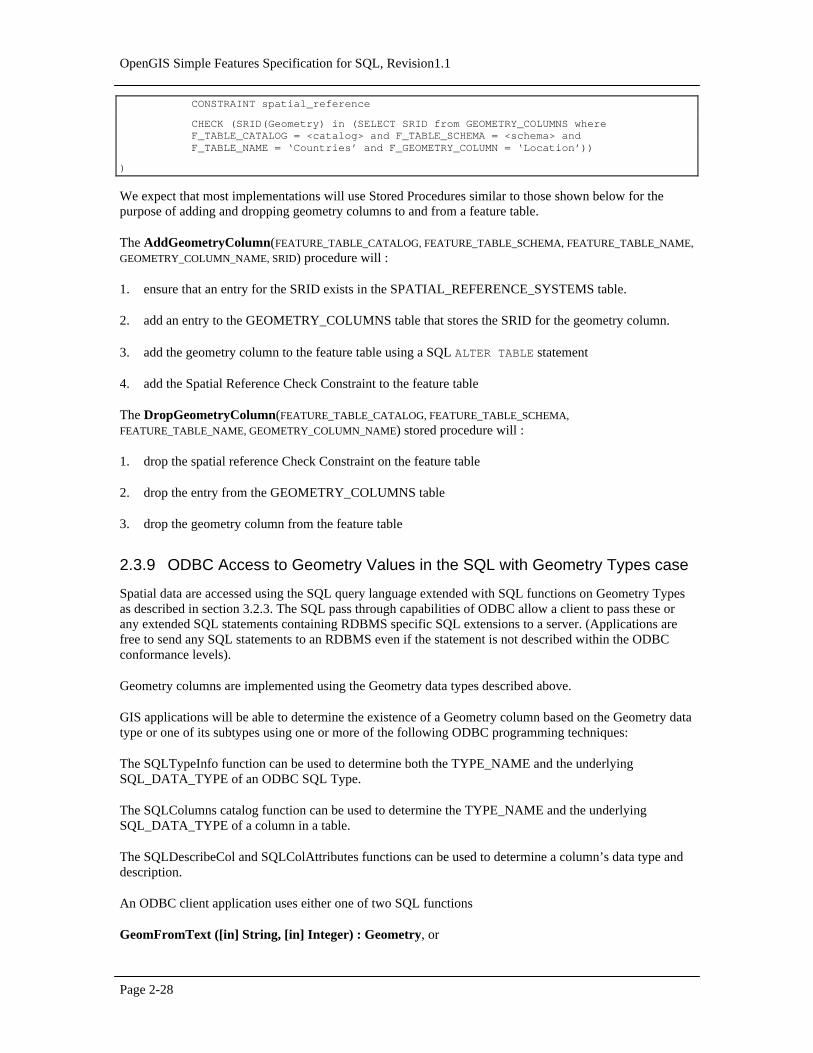
CONSTRAINT spatial_reference
CHECK (SRID(Geometry) in (SELECT SRID from GEOMETRY_COLUMNS where F_TABLE_CATALOG = <catalog> and F_TABLE_SCHEMA = <schema> and F_TABLE_NAME = ‘Countries’ and F_GEOMETRY_COLUMN = ‘Location’))
)
We expect that most implementations will use Stored Procedures similar to those shown below for thepurpose of adding and dropping geometry columns to and from a feature table.
The AddGeometryColumn(FEATURE_TABLE_CATALOG, FEATURE_TABLE_SCHEMA, FEATURE_TABLE_NAME,
GEOMETRY_COLUMN_NAME, SRID) procedure will :
1. ensure that an entry for the SRID exists in the SPATIAL_REFERENCE_SYSTEMS table.
2. add an entry to the GEOMETRY_COLUMNS table that stores the SRID for the geometry column.
3. add the geometry column to the feature table using a SQL ALTER TABLE statement
4. add the Spatial Reference Check Constraint to the feature table
The DropGeometryColumn(FEATURE_TABLE_CATALOG, FEATURE_TABLE_SCHEMA,
FEATURE_TABLE_NAME, GEOMETRY_COLUMN_NAME) stored procedure will :
1. drop the spatial reference Check Constraint on the feature table
2. drop the entry from the GEOMETRY_COLUMNS table
3. drop the geometry column from the feature table
2.3.9 ODBC Access to Geometry Values in the SQL with Geometry Types case
Spatial data are accessed using the SQL query language extended with SQL functions on Geometry Typesas described in section 3.2.3. The SQL pass through capabilities of ODBC allow a client to pass these orany extended SQL statements containing RDBMS specific SQL extensions to a server. (Applications arefree to send any SQL statements to an RDBMS even if the statement is not described within the ODBCconformance levels).
Geometry columns are implemented using the Geometry data types described above.
GIS applications will be able to determine the existence of a Geometry column based on the Geometry datatype or one of its subtypes using one or more of the following ODBC programming techniques:
The SQLTypeInfo function can be used to determine both the TYPE_NAME and the underlyingSQL_DATA_TYPE of an ODBC SQL Type.
The SQLColumns catalog function can be used to determine the TYPE_NAME and the underlyingSQL_DATA_TYPE of a column in a table.
The SQLDescribeCol and SQLColAttributes functions can be used to determine a column’s data type anddescription.
An ODBC client application uses either one of two SQL functions
GeomFromText ([in] String, [in] Integer) : Geometry, or
Chapter 2 Architecture
Page 2-29
GeomFromWKB([in] Binary,[ in] Integer) : Geometry
or their type specific versions (for example, PolygonFromText and PolygonFromWKB) to pass geometryvalues into the database from a client application that represents them using either the well-known text orthe well-known binary representations.
The input arguments to the above functions are ODBC standard character, binary and integer data types(SQL_C_CHAR, SQL_C_BINARY, SQL_C_INTEGER) and clients bind to these parameters usingstandard ODBC binding methods.
An ODBC client application uses either one of two SQL functions
AsText([in]Geometry) : String, or
AsBinary([in]Geometry) : Binary
to extract geometry values from the database as either text or well-known binary values.
The output arguments to the above functions are ODBC standard character and binary data types(SQL_C_CHAR, SQL_C_BINARY) and clients bind to these parameters using standard ODBC bindingmethods.
The above SQL functions are described in sections 3.2.8 and 3.2.9.


Page 3-1
3 Component Specifications
In order to be compliant with this OpenGIS ODBC/SQL specification for geospatial feature collections animplementer shall choose to implement the components described in this section for any one of threealternatives (1a, 1b or 2) listed below and described in this specification:
1. SQL92 implementation of feature tables
a) using numeric SQL types for geometry storage and ODBC access.
b) using binary SQL types for geometry storage and ODBC access.
2. SQL92 with Geometry Types implementation of feature tables supporting both textual and binaryODBC access to geometry.
The components for the SQL92 implementation of feature tables are described in section 3.1. Alternatives1a) and 1b) listed above differ only in the implementation of the geometry table component as described insection 3.1.4.
The components for the SQL92 with Geometry Types implementation of feature tables are described insection 3.2.
3.1 Components—SQL92 Implementation of Feature Tables
The components of the ODBC OpenGIS specification for feature table implementation in a SQL92environment consists of the tables or views discussed in this section. Since the existence of some unknowntable is prerequisite for a view, most of the definitions below are stated as CREATE TABLE statements.Views that create the same logical structure are equally compliant. Table names and column names havebeen restricted to 18 characters in length to allow for the widest possible implementation.
3.1.1 Spatial Reference System Information
3.1.1.1 Component Overview
The Spatial Reference Systems table, which is named SPATIAL_REF_SYS, stores information on eachspatial reference system used in the database.
OpenGIS Simple Features Specification for SQL, Revision1.1
Page 3-2
3.1.1.2 Table or View Constructs
The following CREATE TABLE statement creates an appropriately structured Spatial Reference Systemstable.
CREATE TABLE SPATIAL_REF_SYS
(
SRID INTEGER NOT NULL PRIMARY KEY,
AUTH_NAME VARCHAR (256),
AUTH_SRID INTEGER,
SRTEXT VARCHAR (2048)
)
3.1.1.3 Field Description
The meanings of the attributes in the view are as follows:
• SRID—an integer value that uniquely identifies each Spatial Reference System within a database.
• AUTH_NAME—the name of the standard or standards body that is being cited for this reference system.EPSG would be a valid AUTH_NAME
• AUTH_SRID—the ID of the Spatial Reference System as defined by the Authority cited in AUTH_NAME.
• SRTEXT—The Well-known Text representation of the Spatial Reference System.
3.1.1.4 Exceptions, Errors, and Error Codes
Error handling will be accomplished by using the standard SQL status returns.
3.1.2 Geometry Columns Metadata View
3.1.2.1 Component Overview
The Geometric Columns Metadata view provides metadata information on the spatial reference for eachgeometry column in the database.
3.1.2.2 Table or View Constructs
The following CREATE TABLE statement creates an appropriately structured table. This should be either anactual table or an updateable view so that insertion of reference system information can be done directlywith SQL.
CREATE TABLE GEOMETRY_COLUMNS (
F_TABLE_CATALOG VARCHAR(256) NOT NULL,
F_TABLE_SCHEMA VARCHAR(256) NOT NULL,
F_TABLE_NAME VARCHAR(256) NOT NULL,
F_GEOMETRY_COLUMN VARCHAR(256) NOT NULL,
G_TABLE_CATALOG VARCHAR(256) NOT NULL,
G_TABLE_SCHEMA VARCHAR(256) NOT NULL,
G_TABLE_NAME VARCHAR(256) NOT NULL,
STORAGE_TYPE INTEGER,

Chapter 3 Component Specifications
Page 3-3
GEOMETRY_TYPE INTEGER,
COORD_DIMENSION INTEGER,
MAX_PPR INTEGER,
SRID INTEGER REFERENCES SPATIAL_REF_SYS,
CONSTRAINT GC_PK PRIMARY KEY (F_TABLE_CATALOG, F_TABLE_SCHEMA, F_TABLE_NAME, F_GEOMETRY_COLUMN)
)
3.1.2.3 Field Description
The fields in the Geometric Complex Information view are:
• F_TABLE_CATALOG, F_TABLE_SCHEMA, F_TABLE_NAME—the fully qualified name of the feature tablecontaining the geometry column.
• F_GEOMETRY_COLUMN—the name of the column in the feature table that is the geometry column. Thiscolumn will contain a foreign key reference into the geometry table for a SQL92 implementation.
• G_TABLE_CATALOG, G_TABLE_SCHEMA, G_TABLE_NAME—the name of the geometry table and itsschema and catalog. The geometry table implements the geometry column.
• STORAGE_TYPE—the type of storage being used for this geometry column.
0 = normalized geometry SQL92 implementation.1 = binary geometry SQL92 implementation (Well-known Binary Representation for Geometry).
• GEOMETRY_TYPE—the type of geometry values stored in this column. The use of a non-leaf geometryclass name from the Geometry Object Model described in section 3.1 for a geometry column impliesthat domain of the column corresponds to instances of the class and all of its subclasses.
0 = GEOMETRY1 = POINT2 = CURVE3 = LINESTRING4 = SURFACE5 = POLYGON6 = COLLECTION7 = MULTIPOINT8 = MULTICURVE9 = MULTILINESTRING10 = MULTISURFACE11 = MULTIPOLYGON
• COORD_DIMENSION—the number of ordinates used in the complex, usually corresponds to the numberof dimensions in the spatial reference system.
• MAX_PPR—(This value contains data for the normalized SQL92 geometry implementation only) pointsper row, the number of points stored as ordinate columns in the geometry table.
• SRID—the ID of the spatial reference system used for the coordinate geometry in this table. It is aforeign key reference to the SPATIAL_REF_SYS table.

OpenGIS Simple Features Specification for SQL, Revision1.1
Page 3-4
3.1.2.4 Exceptions, Errors, and Error Codes
Error handling will be accomplished by using the standard SQL status returns for ODBC.
3.1.3 Feature Tables and Views
The basic restriction in this specification for feature tables is that for each geometric attribute they includegeometry via a FOREIGN KEY reference to a geometry table. Feature-to-feature relations would similarlybe defined as FOREIGN KEY references. By [1], features are simply objects that have geometric attributes.In SQL92, these geometric attributes are stored in the geometry tables.
The general format of a feature table would be as follows:
CREATE TABLE <feature-name> (
<FID name> <FID type>,
<feature attributes> <other FID type> REFERENCES <other feature view>,
… (other FID based attributes for feature relations)
… (other attributes for feature)
<geometry attribute 1> <GID type>,
… (other geometric attributes for feature)
PRIMARY KEY <FID name>,
… (other geometric attributes foreign key statements)
FOREIGN KEY <geometric attribute 1> REFERENCES <geometry-table-name-1>,
FOREIGN KEY <FID relation name> REFERENCES <FEATURE table> <other FID name>,
… (other geometric attributes foreign key statements)
)
The geometric attribute Foreign Key reference applies only for the case where the geometry table storesgeometry in binary form. In the case where geometry is stored in normalized form there may be multiplerows in the geometry table corresponding to a single geometry value. In this case the geometry attributereference may be captured by a constraint that checks that the geometry column value stored in the FeatureTable corresponds to the GID value for some row in the Geometry Table.
The foreign key reference to the geometry table name creates an entry in the data dictionary that ties thistable to that geometry table. This is sufficient to identify this table as a feature table. Foreign keys alsodefine feature-to-feature relations. Alternatively, applications may check the GEOMETRY_COLUMNS view,where all geometry columns and their associated feature tables and geometry tables are listed.
3.1.4 Geometry Tables or Views
3.1.4.1 Component Overview
Each Geometry View stores geometry instances corresponding to a geometry column in a feature table.Geometries may be stored as individual ordinate values, using SQL types, or as binary objects, using theOpenGIS Well-known Binary Representation for Geometry. Table schemas for both implementations areprovided.

Chapter 3 Component Specifications
Page 3-5
3.1.4.2 Geometry stored using ODBC/SQL numeric types
3.1.4.3 Table or View Constructs
The following CREATE TABLE statement creates an appropriately structured table for geometry stored asindividual ordinate values using SQL types. Implementations should either use this table format or providestored procedures to create, populate and maintain this table.
CREATE TABLE <table name> (
GID NUMBER NOT NULL,
ESEQ INTEGER NOT NULL,
ETYPE INTEGER NOT NULL,
SEQ INTEGER NOT NULL,
X1 <ordinate type>,
Y1 <ordinate type>,
... <repeated for each ordinate, repeated for each point>
X<max_ppr> <ordinate type>,
Y<max_ppr> <ordinate type>,
...,
<attribute name> <attribute type>
CONSTRAINT GID_PK PRIMARY KEY (GID, ESEQ, SEQ)
)
3.1.4.4 Field Descriptions :
The fields of a geometric view are:
• GIDidentity of this geometry
• ESEQ—identifies multiple components within a geometry
• ETYPE—element type of this primitive element for the geometry. The following values are defined forETYPE:
1 = Point2 = LineString3 = Polygon
• SEQ—identifies the sequence of rows to define a geometry component
• X1—first ordinate of first point
• Y1—second ordinate of first point
• ...(repeated for each ordinate, for this point)
• ...(repeated for each coordinate, for this row)

OpenGIS Simple Features Specification for SQL, Revision1.1
Page 3-6
• X<MAX_PPR>—first ordinate of last point,. The maximum number of points per row ‘MAX_PPR’ isconsistent with the information in the GEOMETRY_COLUMNS table.
• Y<MAX_PPR>—second ordinate of last point
• ...(repeated for each ordinate, for this last point)
• <ATTRIBUTE>other attributes can be carried in the geometry view for specific feature schema
3.1.4.5 Geometry stored using ODBC/SQL binary types
3.1.4.6 Table or View Constructs
The following CREATE TABLE statement creates an appropriately defined table for geometry stored usingthe OpenGIS Well-known Binary Representation for Geometry defined in section 4.3. Implementationsshould either use this table format or provide stored procedures to create, populate and maintain this table.
CREATE TABLE <table name> (
GID NUMBER NOT NULL PRIMARY KEY,
XMIN <ordinate type>,
YMIN <ordinate type>,
XMAX <ordinate type>,
YMAX <ordinate type>,
WKB_GEOMETRY VARBINARY,
<attribute name> <attribute type>
)
3.1.4.7 Field Descriptions
The fields of a geometric view are:
• GID—identity of this geometry
• XMIN—the minimum x-coordinate of the geometry bounding box
• YMIN—the minimum y-coordinate of the geometry bounding box
• XMAX—the maximum x-coordinate of the geometry bounding box
• YMAX—the maximum y-coordinate of the geometry bounding box
• WKB_GEOMETRY—the well-known binary representation of the geometry
• <ATTRIBUTE>—other attributes can be carried in the geometry view for specific feature schema
3.1.4.8 Exceptions, Errors, and Error Codes
Error handling will use the standard SQL status returns for ODBC.

Chapter 3 Component Specifications
Page 3-7
3.1.5 Operators
No SQL92 spatial operators are defined as part of this specification.
3.2 Components—SQL92 with Geometry Types Implementation of FeatureTables
The components of the ODBC OpenGIS specification for feature table implementation in a SQL92 withGeometry Types environment consists of the tables or views, SQL types and SQL functions discussed inthis section.
Since the existence of some unknown table is prerequisite for a view, most of the definitions below arestated as CREATE TABLE statements. Views that create the same logical structure are equally compliant.
3.2.1 Spatial Reference System Information View
3.2.1.1 Component Overview
This component is identical to the corresponding Component described for the SQL92 implementation:
3.2.1.2 Table or View Constructs
The following CREATE TABLE statement creates an appropriately structured Spatial Reference Systemstable.
CREATE TABLE SPATIAL_REF_SYS
(
SRID INTEGER NOT NULL PRIMARY KEY,
AUTH_NAME VARCHAR (256),
AUTH_SRID INTEGER,
SRTEXT VARCHAR (2048)
)
3.2.1.3 Field Description
The meanings of the attributes in the view are as follows:
• SRID—an integer value that uniquely identifies each Spatial Reference System within a database.
• AUTH_NAME—the name of the standard or standards body that is being cited for this reference system.EPSG would be a valid AUTH_NAME
• AUTH_SRID—the ID of the Spatial Reference System as defined by the Authority cited in AUTH_NAME.
• SRTEXT—The Well-known Text representation of the Spatial Reference System.
3.2.1.4 Exceptions, Errors, and Error Codes
Error handling will be accomplished by using the standard SQL status returns.

OpenGIS Simple Features Specification for SQL, Revision1.1
Page 3-8
3.2.2 Geometry Columns Metadata View
3.2.2.1 Component Overview
The Geometric Columns Information view provides metadata information on the spatial reference for eachgeometry column in the database. The columns for this view in the SQL92 with Geometry Typesimplementation are a subset of the columns in the SQL92 implementation.
3.2.2.2 Table or View Constructs
The following CREATE TABLE statement creates an appropriately structured table. This should be either anactual table or an updateable view so that insertion of reference system information can be done directlywith SQL.
CREATE TABLE GEOMETRY_COLUMNS (
F_TABLE_CATALOG VARCHAR(256) NOT NULL,
F_TABLE_SCHEMA VARCHAR(256) NOT NULL,
F_TABLE_NAME VARCHAR(256) NOT NULL,
F_GEOMETRY_COLUMN VARCHAR(256) NOT NULL,
COORD_DIMENSION INTEGER,
SRID INTEGER REFERENCES SPATIAL_REF_SYS,
CONSTRAINT GC_PK PRIMARY KEY (F_TABLE_CATALOG, F_TABLE_SCHEMA, F_TABLE_NAME, F_GEOMETRY_COLUMN)
)
3.2.2.3 Field Description
The fields in the Geometric Complex Information view are:
• F_TABLE_CATALOG, F_TABLE_SCHEMA, F_TABLE_NAME—the fully qualified name of the featuretable containing the geometry column.
• F_GEOMETRY_COLUMN—the name of the geometry column in the feature table.
• COORD_DIMENSION—the coordinate dimension for the geometry values in this column, which will beequal to the number of dimensions in the spatial reference system.
• SRID—the ID of the spatial reference system used for the coordinate geometry in this table. It is aforeign key reference to the SPATIAL_REFERENCES table.
3.2.2.4 Exceptions, Errors, and Error Codes
Error handling will be accomplished by using the standard SQL status returns for ODBC.
3.2.3 SQL Geometry Types
3.2.3.1 Component Overview
The SQL Geometry Types extend the set of available SQL92 types to include Geometry Types.
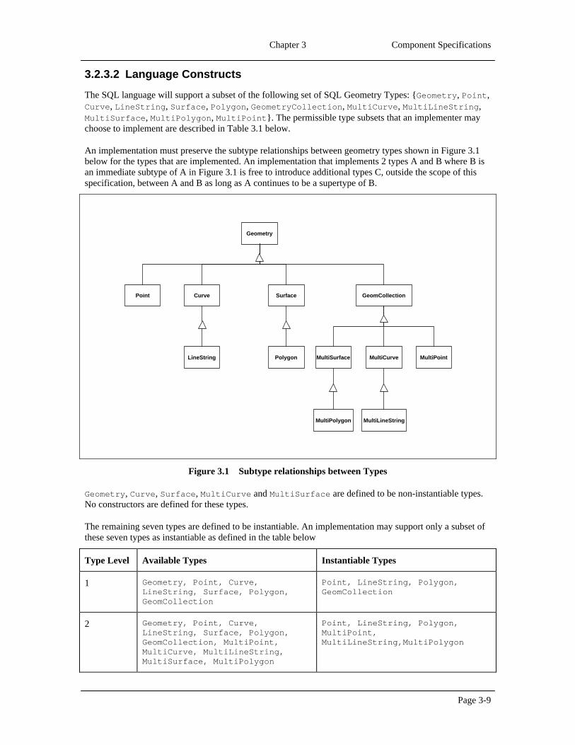
Chapter 3 Component Specifications
Page 3-9
3.2.3.2 Language Constructs
The SQL language will support a subset of the following set of SQL Geometry Types: {Geometry, Point,Curve, LineString, Surface, Polygon, GeometryCollection, MultiCurve, MultiLineString,MultiSurface, MultiPolygon, MultiPoint}. The permissible type subsets that an implementer maychoose to implement are described in Table 3.1 below.
An implementation must preserve the subtype relationships between geometry types shown in Figure 3.1below for the types that are implemented. An implementation that implements 2 types A and B where B isan immediate subtype of A in Figure 3.1 is free to introduce additional types C, outside the scope of thisspecification, between A and B as long as A continues to be a supertype of B.
MultiPoint
SurfaceCurvePoint
LineString
GeomCollection
Geometry
MultiCurve
MultiLineString
MultiSurface
MultiPolygon
Polygon
Figure 3.1Subtype relationships between Types
Geometry, Curve, Surface, MultiCurve and MultiSurface are defined to be non-instantiable types.No constructors are defined for these types.
The remaining seven types are defined to be instantiable. An implementation may support only a subset ofthese seven types as instantiable as defined in the table below
Type Level Available Types Instantiable Types
1 Geometry, Point, Curve,LineString, Surface, Polygon,GeomCollection
Point, LineString, Polygon,GeomCollection
2 Geometry, Point, Curve,LineString, Surface, Polygon,GeomCollection, MultiPoint,MultiCurve, MultiLineString,MultiSurface, MultiPolygon
Point, LineString, Polygon,MultiPoint,MultiLineString,MultiPolygon

OpenGIS Simple Features Specification for SQL, Revision1.1
Page 3-10
3 Geometry, Point, Curve,LineString, Surface, Polygon,GeomCollection, MultiPoint ,MultiCurve, MultiLineString,MultiSurface, MultiPolygon
Point, LineString, Polygon,GeomCollection, MultiPoint,MultiLineString, MultiPolygon
Table 3.1Available and instantiable types by implementation type level
Any implemented SQL geometry type may be used as the type for a column. Declaring a column to be of aparticular type implies that any instance of the type or of any of its subtypes may be stored in the column.
3.2.4 Feature Tables and Views
3.2.4.1 Component Overview
The basic restriction in this specification for feature tables is that each geometric attribute is modeled usinga column whose type corresponds to a SQL Geometry Type as defined in section 3.2.3. Feature-to-featurerelations are defined as FOREIGN KEY references.
3.2.4.2 Table or View Constructs
The general format of a feature table in the SQL92 with Geometry Types implementation shall be asfollows:
CREATE TABLE <feature-name> (
<FID name> <FID type>,
<feature attributes> <other FID type> REFERENCES <other feature view>,
… (other FID based attributes for feature relations)
… (other attributes for feature)
<geometry attribute 1> <Geometry type>,
… (other geometric attributes for feature)
PRIMARY KEY <FID name>,
FOREIGN KEY <FID relation name> REFERENCES <FEATURE table> <other FID name>
CONSTRAINT SRS_1 CHECK (SRID(<geometry attribute 1>) in (SELECT SRID from GEOMETRY_COLUMNS where F_TABLE_CATALOG = <catalog> and F_TABLE_SCHEMA = <schema> and F_TABLE_NAME = <feature-name> and F_GEOMETRY_COLUMN = <geometry attribute 1>))
... (spatial reference constraints for other geometric attributes)
)
The use of a SQL Geometry Type for one of the columns in the table identifies this table as a feature table.Alternatively, applications may check the GEOMETRY_COLUMNS view, where all geometry columns andtheir associated feature tables and geometry tables are listed.
3.2.4.3 Exceptions, Errors, and Error Codes
Error handling will be accomplished by using the standard SQL status returns.

Chapter 3 Component Specifications
Page 3-11
3.2.5 SQL Textual Representation of Geometry
3.2.5.1 Component Overview
Each Geometry Type has a Well-known Text representation that may be used both to construct newinstances of the type and to convert existing instances to textual form for alphanumeric display.
3.2.5.2 Language Constructs
The Well-known Text representation of Geometry is defined below; the notation {}* denotes 0 or morerepetitions of the tokens within the braces, the braces do not appear in the output token list. The textrepresentation of the instantiable geometric types implemented shall conform to this grammar.
<Geometry Tagged Text> :=
<Point Tagged Text>
| <LineString Tagged Text>
| <Polygon Tagged Text>
| <MultiPoint Tagged Text>
| <MultiLineString Tagged Text>
| <MultiPolygon Tagged Text>
| <GeometryCollection Tagged Text>
<Point Tagged Text> :=
POINT <Point Text>
<LineString Tagged Text> :=
LINESTRING <LineString Text>
<Polygon Tagged Text> :=
POLYGON <Polygon Text>
<MultiPoint Tagged Text> :=
MULTIPOINT <Multipoint Text>
<MultiLineString Tagged Text> :=
MULTILINESTRING <MultiLineString Text>
<MultiPolygon Tagged Text> :=
MULTIPOLYGON <MultiPolygon Text>
<GeometryCollection Tagged Text> :=
GEOMETRYCOLLECTION <GeometryCollection Text>
<Point Text> := EMPTY | ( <Point> )
<Point> := <x> <y>
<x> := double precision literal
<y> := double precision literal
<LineString Text> := EMPTY
| ( <Point > {, <Point > }* )
<Polygon Text> := EMPTY
| ( <LineString Text > {, < LineString Text > }*)
<Multipoint Text> := EMPTY
| ( <Point Text > {, <Point Text > }* )
<MultiLineString Text> := EMPTY

OpenGIS Simple Features Specification for SQL, Revision1.1
Page 3-12
| ( <LineString Text > {, < LineString Text > }* )
<MultiPolygon Text> := EMPTY
| ( < Polygon Text > {, < Polygon Text > }* )
<GeometryCollection Text> := EMPTY
| ( <Geometry Tagged Text> {, <Geometry Tagged Text> }* )
The above grammar has been designed to support a compact and readable textual representation ofgeometric instances. The representation of a geometry that consists of a set of homogeneous componentsdoes not include the tags for each embedded component.
3.2.5.3 Examples
Examples of SQL textual representations of Geometry Types are shown below. The coordinates are shownas integer values; coordinates may be any double precision value.
Geometry Type SQL Text Literal Representation Comment
Point ‘POINT (10 10)’ a Point
LineString ‘LINESTRING ( 10 10, 20 20, 30 40)’ a LineString with 3 points
Polygon ‘POLYGON ((10 10, 10 20, 20 20, 20 15, 10 10))’
a Polygon with 1 exteriorring and 0 interior rings
Multipoint ‘MULTIPOINT (10 10, 20 20)’ a MultiPoint with 2 point
MultiLineString ‘MULTILINESTRING ((10 10, 20 20), (15 15, 30 15))’
a MultiLineString with2 linestrings
MultiPolygon ‘MULTIPOLYGON ( ((10 10, 10 20, 20 20, 20 15, 10 10)), ((60 60, 70 70, 80 60, 60 60 ) ))’
a MultiPolygon with 2polygons
GeomCollection ‘GEOMETRYCOLLECTION (POINT (10 10), POINT (30 30), LINESTRING (15 15, 20 20))’
a GeometryCollectionconsisting of 2 Point valuesand a LineString value
3.2.6 SQL Functions for Constructing a Geometry Value given its Well-knownText Representation
3.2.6.1 Component Overview
The functions are used to construct Geometry instances from their text representations.
3.2.6.2 Language Constructs
The GeomFromText function, takes a geometry textual representation (a <Geometry Tagged Text> asdescribed in the grammar above), and a Spatial Reference System ID (SRID) and creates an instance of theappropriate geometry type. This function plays the role of the Geometry factory in SQL.
An implementation shall substitute an SQL type suitable for representing text data (e.g., VARCHAR) for thetype String below.
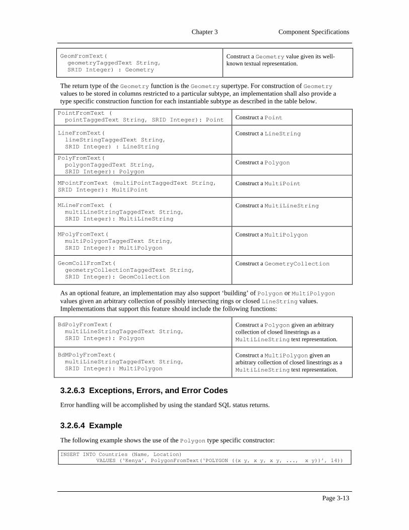
Chapter 3 Component Specifications
Page 3-13
GeomFromText( geometryTaggedText String, SRID Integer) : Geometry
Construct a Geometry value given its well-known textual representation.
The return type of the Geometry function is the Geometry supertype. For construction of Geometryvalues to be stored in columns restricted to a particular subtype, an implementation shall also provide atype specific construction function for each instantiable subtype as described in the table below.
PointFromText ( pointTaggedText String, SRID Integer): Point Construct a Point
LineFromText( lineStringTaggedText String, SRID Integer) : LineString
Construct a LineString
PolyFromText( polygonTaggedText String, SRID Integer): Polygon
Construct a Polygon
MPointFromText (multiPointTaggedText String,SRID Integer): MultiPoint
Construct a MultiPoint
MLineFromText ( multiLineStringTaggedText String, SRID Integer): MultiLineString
Construct a MultiLineString
MPolyFromText( multiPolygonTaggedText String, SRID Integer): MultiPolygon
Construct a MultiPolygon
GeomCollFromTxt( geometryCollectionTaggedText String, SRID Integer): GeomCollection
Construct a GeometryCollection
As an optional feature, an implementation may also support ‘building’ of Polygon or MultiPolygonvalues given an arbitrary collection of possibly intersecting rings or closed LineString values.Implementations that support this feature should include the following functions:
BdPolyFromText( multiLineStringTaggedText String, SRID Integer): Polygon
Construct a Polygon given an arbitrarycollection of closed linestrings as aMultiLineString text representation.
BdMPolyFromText( multiLineStringTaggedText String, SRID Integer): MultiPolygon
Construct a MultiPolygon given anarbitrary collection of closed linestrings as aMultiLineString text representation.
3.2.6.3 Exceptions, Errors, and Error Codes
Error handling will be accomplished by using the standard SQL status returns.
3.2.6.4 Example
The following example shows the use of the Polygon type specific constructor:
INSERT INTO Countries (Name, Location)VALUES (‘Kenya’, PolygonFromText(‘POLYGON ((x y, x y, x y, ..., x y))’, 14))

OpenGIS Simple Features Specification for SQL, Revision1.1
Page 3-14
3.2.7 SQL Functions for Constructing a Geometry Value given its Well-knownBinary Representation
3.2.7.1 Component Overview
The functions are used to construct geometry instances from their well-known binary representations.
3.2.7.2 Language Constructs
The GeomFromWKB function, takes a well-known binary representation of geometry (WKBGeometry asdescribed in section 3.3) and a Spatial Reference System ID (SRID) and creates an instance of theappropriate geometry type. This function plays the role of the Geometry Factory in SQL. Animplementation shall substitute an SQL type used to represent binary values for the type Binary in thedefinitions below.
GeomFromWKB(WKBGeometry Binary, SRID Integer) : Geometry
Construct a Geometry value given its well-knownbinary representation.
The return type of the Geometry function is the Geometry supertype. For construction of Geometryvalues to be stored in columns restricted to a particular subtype, an implementation shall also provide atype specific construction function for each instantiable subtype as described in the table below (the well-known binary representations for each Geometry type are as described in section 3.3).
PointFromWKB (WKBPoint Binary, SRID Integer): PointConstruct a Point
LineFromWKB(WKBLineString Binary, SRID Integer) : LineString
Construct a LineString
PolyFromWKB(WKBPolygon Binary, SRID Integer): PolygonConstruct a Polygon
MPointFromWKB (WKBMultiPoint Binary, SRID Integer): MultiPoint
Construct a MultiPoint
MLineFromWKB (WKBMultiLineString Binary, SRID Integer): MultiLineString
Construct aMultiLineString
MPolyFromWKB (WKBMultiPolygon Binary, SRID Integer): MultiPolygon
Construct a MultiPolygon
GeomCollFromWKB(WKBGeometryCollection Binary, SRID Integer): GeomCollection
Construct aGeometryCollection
As an optional feature, an implementation may also support the ‘building’ of Polygon or MultiPolygonvalues given an arbitrary collection of possibly intersecting rings or closed LineString values.Implementations that support this feature should include the following functions:
BdPolyFromWKB(WKBMultiLineString Binary, SRID Integer): Polygon
Construct a Polygon given an arbitrarycollection of closed linestrings as aMultiLineString binary representation.

Chapter 3 Component Specifications
Page 3-15
BdMPolyFromWKB(WKBMultiLineString Binary, SRID Integer): MultiPolygon
Construct a MultiPolygon given anarbitrary collection of closed linestrings as aMultiLineString binary representation.
3.2.7.3 Exceptions, Errors, and Error Codes
Error handling will be accomplished by using the standard SQL status returns.
3.2.7.4 Examples
The following example shows the use of the binary Polygon type specific constructor in Dynamic SQL,the :wkb and :srid parameters are bound to application program variables containing the binaryrepresentation of a Polygon and of the SRID respectively :
INSERT INTO Countries (Name, Location)VALUES (‘Kenya’, PolygonFromWKB(:wkb, :srid))
3.2.8 SQL functions for obtaining the Well-known Text Representation of aGeometry
3.2.8.1 Component Overview
This function returns the well-known textual representation for a Geometry.
3.2.8.2 Language Constructs
The AsText function takes a single argument of type Geometry and returns its well-known textualrepresentation. This function applies to all subtypes of Geometry.
AsText (g Geometry) : String Returns the well-known textual representation
3.2.8.3 Exceptions, Errors, and Error Codes
Error handling will be accomplished by using the standard SQL status returns.
3.2.8.4 Examples
The following example shows the use of the AsText function to extract the name and textualrepresentation of geometry of all countries whose names begin with the letter K.
SELECT Name, AsText(Location) FROM Countries WHERE Name LIKE ‘K%’
3.2.9 SQL functions for obtaining the Well-known Binary Representation of aGeometry
3.2.9.1 Component Overview
This function returns the well-known binary representation for a Geometry

OpenGIS Simple Features Specification for SQL, Revision1.1
Page 3-16
3.2.9.2 Language Constructs
The AsBinary function takes a single argument of type Geometry and returns its well-known binaryrepresentation. This function applies to all subtypes of Geometry.
AsBinary (g Geometry) : Binary Returns the well-known binary representation
3.2.9.3 Exceptions, Errors, and Error Codes
Error handling will be accomplished by using the standard SQL status returns.
3.2.9.4 Example
The following example shows the use of the AsBinary function to extract the name and well-knownbinary representation of geometry for all countries whose names begin with the letter K.
SELECT Name, AsBinary(Location) FROM Countries WHERE Name LIKE ‘K%’
3.2.10 SQL Functions on Type Geometry
3.2.10.1 Component Description
In all operations on the Geometry type, geometric calculations shall be done in the spatial reference systemof the first geometric object. Returned objects shall be in the spatial reference system of the first geometricobject unless explicitly stated otherwise.
The following SQL functions apply to all subtypes of Geometry.
3.2.10.2 Language Constructs
Dimension(g Geometry) : Integer Returns the dimension of the Geometry, which is less than orequal to the dimension of the coordinate space.
GeometryType(g Geometry) : String Returns the name of the instantiable subtype of Geometry ofwhich this instance is a member, as a String.
AsText(g Geometry) : String Returns the well-known textual representation
AsBinary(g Geometry) : Binary Returns the well-known binary representation
SRID(g Geometry) : Integer Returns the Spatial Reference System ID for this Geometry.
IsEmpty(g Geometry) : Integer The return type is Integer, with a return value of 1 for TRUE, 0for FALSE, and –1 for UNKNOWN corresponding to a functioninvocation on NULL arguments.
TRUE if this Geometry corresponds to the empty set.

Chapter 3 Component Specifications
Page 3-17
IsSimple(g Geometry): Integer The return type is Integer, with a return value of 1 for TRUE, 0for FALSE, and –1 for UNKNOWN corresponding to a functioninvocation on NULL arguments.
TRUE if this Geometry is simple, as defined in the GeometryModel.
Boundary(g Geometry) : Geometry Returns a Geometry that is the combinatorial boundary of g asdefined in the Geometry Model.
Envelope(g Geometry) : Geometry Returns the rectangle bounding g as a Polygon. The polygon isdefined by the corner points of the bounding box ((MINX,MINY),(MAXX, MINY), (MAXX, MAXY), (MINX,MAXY), (MINX, MINY)).
3.2.10.3 Exceptions, Errors, and Error Codes
Error handling will be accomplished by using the standard SQL status returns.
3.2.11 SQL Functions on Type Point
3.2.11.1 Component Description
The following SQL functions are defined on Point.
3.2.11.2 Language Constructs
X(p Point) : Double Precision Return the x-coordinate of Point p as a Double Precisionnumber
Y(p Point) : Double Precision Return the y-coordinate of Point p as a Double Precisionnumber
3.2.11.3 Exceptions, Errors, and Error Codes
Error handling will be accomplished by using the standard SQL status returns.
3.2.12 SQL Functions on Type Curve
3.2.12.1 Component Overview
The following SQL functions apply to all subtypes of Curve.
3.2.12.2 Language Constructs
StartPoint(c Curve) : Point Return a Point containing the first point of c
EndPoint(c Curve) : Point Return a Point containing the last point of c

OpenGIS Simple Features Specification for SQL, Revision1.1
Page 3-18
IsClosed(c Curve) : Integer The return type is Integer, with a return value of 1 forTRUE, 0 for FALSE, and –1 for UNKNOWN corresponding to afunction invocation on NULL arguments.
Return TRUE if c is closed, i.e., ifStartPoint(c) = EndPoint(c)
IsRing(c Curve) : Integer The return type is Integer, with a return value of 1 forTRUE, 0 for FALSE, and –1 for UNKNOWN corresponding to afunction invocation on NULL arguments.
Return TRUE if c is a Ring, i.e., if c is closed and simple. Asimple curve does not pass through the same point more thanonce.
Length(c Curve) : Double Precision Return the length of c
3.2.12.3 Exceptions, Errors, and Error Codes
Error handling will be accomplished by using the standard SQL status returns.
3.2.13 SQL Functions on Type LineString
3.2.13.1 Component Overview :
The following SQL functions apply to LineString.
3.2.13.2 Language Constructs :
NumPoints(l LineString) : Integer Return the number of points in the LineString.
PointN(l LineString, n Integer) : Point Return a Point containing point n of l
3.2.13.3 Exceptions, Errors, and Error Codes
Error handling will be accomplished by using the standard SQL status returns.
3.2.14 SQL Functions on Type Surface
3.2.14.1 Component Overview
The following SQL functions apply to all subtypes of Surface.
3.2.14.2 Language Constructs
Centroid(s Surface) : Point Return the centroid of s, which may lie outside s
PointOnSurface(s Surface) : Point Return a Point guaranteed to lie on the surface
Area(s Surface) : Double Precision Return the area of s

Chapter 3 Component Specifications
Page 3-19
3.2.14.3 Exceptions, Errors, and Error Codes
Error handling will be accomplished by using the standard SQL status returns.
3.2.15 SQL Functions on Type Polygon
3.2.15.1 Component Overview
The following SQL functions apply to Polygon.
3.2.15.2 Language Constructs
ExteriorRing(p Polygon) : LineString Return the exterior ring of p.
NumInteriorRing(p Polygon) : Integer Return the number of interior rings.
InteriorRingN(p Polygon, n Integer) : LineString Return the nth interior ring. The order ofrings is not geometrically significant.
3.2.15.3 Exceptions, Errors, and Error Codes
Error handling will be accomplished by using the standard SQL status returns.
3.2.16 SQL Functions on Type GeomCollection
3.2.16.1 Component Overview
The following SQL functions apply to GeomCollection and all of its subtypes.
3.2.16.2 Language Constructs
NumGeometries(g GeomCollection) : Integer Return the number of geometries in thecollection.
GeometryN(g GeomCollection, n Integer) : Geometry
Return the nth geometry in the collection. Theorder of the elements in the collection is notgeometrically significant.
3.2.16.3 Exceptions, Errors, and Error Codes
Error handling will be accomplished by using the standard SQL status returns.
3.2.17 SQL Functions on Type MultiCurve
3.2.17.1 Component Overview
The following SQL functions apply to all subtypes of MultiCurve.

OpenGIS Simple Features Specification for SQL, Revision1.1
Page 3-20
3.2.17.2 Language Constructs
IsClosed(mc MultiCurve) : Integer The return type is Integer, with a return value of 1for TRUE, 0 for FALSE, and –1 for UNKNOWNcorresponding to a function invocation on NULLarguments.
Return TRUE if mc is closed.
Length(mc MultiCurve) : Double Precision Return the length of mc.
3.2.17.3 Exceptions, Errors, and Error Codes
Error handling will be accomplished by using the standard SQL status returns.
3.2.18 SQL Functions on Type MultiSurface
3.2.18.1 Component Overview
The following SQL functions apply to all subtypes of MultiSurface.
3.2.18.2 Language Constructs
Centroid(ms MultiSurface) : Point Return the centroid of ms, which may lie outside ms
PointOnSurface(ms MultiSurface) : Point Return a Point guaranteed to lie on the multi surface
Area(ms MultiSurface) : Double Precision Return the area of ms
3.2.18.3 Exceptions, Errors, and Error Codes
Error handling will be accomplished by using the standard SQL status returns.
3.2.19 SQL functions that test Spatial Relationships
3.2.19.1 Component Overview
The following functions test named spatial relationships between two geometries. The specific definitionsof these spatial relationships in terms of the DE-9IM may be found in section 2.1.13.2.
3.2.19.2 Language Constructs:
Equals(g1 Geometry,g2 Geometry) : Integer The return type is Integer, with a return valueof 1 for TRUE, 0 for FALSE, and –1 forUNKNOWN corresponding to a functioninvocation on NULL arguments.
TRUE if g1 and g2 are equal.

Chapter 3 Component Specifications
Page 3-21
Disjoint(g1 Geometry, g2 Geometry) : Integer The return type is Integer, with a return valueof 1 for TRUE, 0 for FALSE, and –1 forUNKNOWN corresponding to a functioninvocation on NULL arguments.
TRUE if the intersection of g1 and g2 is theempty set.
Touches(g1 Geometry, g2 Geometry) : Integer The return type is Integer, with a return valueof 1 for TRUE, 0 for FALSE, and –1 forUNKNOWN corresponding to a functioninvocation on NULL arguments.
TRUE if the only points in common betweeng1 and g2 lie in the union of the boundariesof g1 and g2.
Within(g1 Geometry, g2 Geometry) : Integer The return type is Integer, with a return valueof 1 for TRUE, 0 for FALSE, and –1 forUNKNOWN corresponding to a functioninvocation on NULL arguments.
TRUE if g1 is completely contained in g2.
Overlaps(g1 Geometry, g2 Geometry) : Integer The return type is Integer, with a return valueof 1 for TRUE, 0 for FALSE, and –1 forUNKNOWN corresponding to a functioninvocation on NULL arguments.
TRUE if the intersection of g1 and g2 resultsin a value of the same dimension as g1 andg2 that is different from both g1 and g2.
Crosses(g1 Geometry, g2 Geometry) : Integer The return type is Integer, with a return valueof 1 for TRUE, 0 for FALSE, and –1 forUNKNOWN corresponding to a functioninvocation on NULL arguments.
TRUE if the intersection of g1 and g2 resultsin a value whose dimension is less than themaximum dimension of g1 and g2 and theintersection value includes points interior toboth g1 and g2, and the intersection value isnot equal to either g1 or g2.
Intersects(g1 Geometry, g2 Geometry) :Integer
The return type is Integer, with a return valueof 1 for TRUE, 0 for FALSE, and –1 forUNKNOWN corresponding to a functioninvocation on NULL arguments.
Convenience predicate: TRUE if theintersection of g1 and g2 is not empty.
Intersects(g1, g2 ) ⇔ Not (Disjoint(g1, g2 ))

OpenGIS Simple Features Specification for SQL, Revision1.1
Page 3-22
Contains(g1 Geometry, g2 Geometry) : Integer The return type is Integer, with a return valueof 1 for TRUE, 0 for FALSE, and –1 forUNKNOWN corresponding to a functioninvocation on NULL arguments.
Convenience predicate: TRUE if g2 iscompletely contained in g1.
Contains(g1, g2 ) ⇔ Within(g2 , g1)
The following function tests if the specified spatial relationship between two geometry values exists, wherethe spatial relationship is expressed as a string encoding the acceptable values for the DE-9IM between thetwo geometries, as described in the Geometry Object Model.
Relate(g1 Geometry, g2 Geometry, patternMatrix String) : Integer
The return type is Integer, with a returnvalue of 1 for TRUE, 0 for FALSE, and –1 forUNKNOWN corresponding to a functioninvocation on NULL arguments.
Returns TRUE if the spatial relationshipspecified by the patternMatrix holds.
3.2.19.3 Exceptions, Errors, and Error Codes
Error handling will be accomplished by using the standard SQL status returns.
3.2.19.4 Example Queries
The functions and predicates in this section allow the expression of detailed spatial relationship queries.
Return all parcels that intersect a specified polygon:
SELECT Parcel.Name, Parcel.Id FROM ParcelsWHERE Intersects(Parcels.Location, PolygonFromWKB(:wkb, : srid)) = 1
Return all parcels completely contained in a specified polygon:
SELECT Parcel.Name, Parcel.Id FROM ParcelsWHERE Within(Parcels. Location, PolygonFromWKB(:wkb, :srid)) = 1
The following adjacency query may be used to select all parcels that are ‘adjacent’ to a query parcel andshare one or more boundary lines with a query parcel while excluding parcels that share only corner points.
SELECT Parcel.Name, Parcel.Id FROM ParcelsWHERE Touches(Parcels. Location, PolygonFromWKB(:wkb, :srid)) = 1 and
Overlaps(Boundary(Parcels. Location), Boundary(PolygonFromWKB(:wkb,:srid))) = 1
3.2.20 SQL Functions for Distance Relationships
3.2.20.1 Component Overview
The distance function can be used to calculate the distance between two values of type Geometry.

Chapter 3 Component Specifications
Page 3-23
3.2.20.2 Language Constructs
Distance(g1 Geometry, g2 Geometry) : Double Precision
Return the distance between g1 and g2.
3.2.20.3 Exceptions, Errors, and Error Codes
Error handling will be accomplished by using the standard SQL status returns.
3.2.20.4 Example QuerySELECT Airport.Name FROM AirportsWHERE Distance(PointFromText(:pointTaggedText, :srid), Airport.Location) < 2000
3.2.21 SQL Functions that implement Spatial Operators
3.2.21.1 Component Overview
These functions implement set-theoretic and constructive geometry operations on geometry values. Theseoperations are defined for all types of Geometry.
3.2.21.2 Language Constructs
Intersection (g1 Geometry, g2 Geometry) : Geometry
Return a Geometry that is the set intersection ofgeometries g1 and g2.
Difference (g1 Geometry, g2 Geometry) : Geometry
Return a Geometry that is the closure of the setdifference of g1 and g2.
Union (g1 Geometry, g2 Geometry) : Geometry
Return a Geometry that is the set union of g1 and g2.
SymDifference(g1 Geometry, g2 Geometry) : Geometry
Return a Geometry that is the closure of the setsymmetric difference of g1 and g2 (logical XOR ofspace).
Buffer (g1 Geometry, d Double Precision) : Geometry
Return as Geometry defined by buffering a distance daround g1, where d is in the distance units for the SpatialReference of g1.
ConvexHull(g1 Geometry) : Geometry Return a Geometry that is the convex hull of g1.
3.2.21.3 Exceptions, Errors, and Error Codes
Error handling will be accomplished by using the standard SQL status returns.
3.2.21.4 Example Query
The following query returns the name of the state and the fragment(s) of the state that fall within the querypolygon for each state that intersects the query polygon.
SELECT States.Name, Intersection(PolygonFromWKB(:wkb, :srid), States.Location)
FROM States
OpenGIS Simple Features Specification for SQL, Revision1.1
Page 3-24
WHERE Intersects(PolygonFromWKB(:wkb, :srid), States.Location)
3.2.22 SQL Function usage and References to Geometry
The SQL Functions that operate on Geometry Types have been defined above to take geometry values asarguments. This conforms to the model for value based ADTs under SQL3.
As described in section 2.3.5, a SQL Type may also support the concept of persistent references toinstances of the Type. To support the latter type of implementation, a reference to a geometry type instance,REF(Geometry), may be used in place of a Geometry value in the SQL functions defined in this section.
3.3 The Well-known Binary Representation for Geometry (WKBGeometry)
3.3.1 Component Overview
The Well-known Binary Representation for Geometry (WKBGeometry), provides a portable representationof a Geometry value as a contiguous stream of bytes. It permits Geometry values to be exchangedbetween an ODBC client and an SQL database in binary form.
3.3.2 Component Description
The Well-known Binary Representation for Geometry is obtained by serializing a geometry instance as asequence of numeric types drawn from the set {Unsigned Integer, Double} and then serializing eachnumeric type as a sequence of bytes using one of two well defined, standard, binary representations fornumeric types (NDR, XDR). The specific binary encoding (NDR or XDR) used for a geometryrepresentation is described by a one byte tag that precedes the serialized bytes. The only difference betweenthe two encodings of geometry is one of byte order, the XDR encoding is Big Endian, the NDR encoding isLittle Endian.
3.3.2.1 Numeric Type Definitions
An Unsigned Integer is a 32-bit (4-byte) data type that encodes a nonnegative integer in the range [0,4294967295].
A Double is a 64-bit (8-byte) double precision data type that encodes a double precision number using theIEEE 754 double precision format
The above definitions are common to both XDR and NDR.
3.3.2.2 XDR (Big Endian) Encoding of Numeric Types
The XDR representation of an Unsigned Integer is Big Endian (most significant byte first).
The XDR representation of a Double is Big Endian (sign bit is first byte).
3.3.2.3 NDR (Little Endian) Encoding of Numeric Types
The NDR representation of an Unsigned Integer is Little Endian (least significant byte first).
The NDR representation of a Double is Little Endian (sign bit is last byte).

Chapter 3 Component Specifications
Page 3-25
3.3.2.4 Conversion between the NDR and XDR representations ofWKBGeometry
Conversion between the NDR and XDR data types for Unsigned Integer and Double numbers is asimple operation involving reversing the order of bytes within each Unsigned Integer or Doublenumber in the representation.
3.3.2.5 Relationship to other COM and CORBA data transfer protocols
The XDR representation for Unsigned Integer and Double numbers described above is also thestandard representation for Unsigned Integer and for Double number in the CORBA Standard StreamFormat for Externalized Object Data that is described as part of the CORBA Externalization ServiceSpecification [15].
The NDR representation for Unsigned Integer and Double number described above is also thestandard representation for Unsigned Integer and for Double number in the DCOM protocols that isbased on DCE RPC and NDR [16].
3.3.2.6 Description of WKBGeometry Representations
The Well-known Binary Representation for Geometry is described below. The basic building block is therepresentation for a Point, which consists of two Double numbers. The representations for othergeometries are built using the representations for geometries that have already been defined.
// Basic Type definitions
// byte : 1 byte
// uint32 : 32 bit unsigned integer (4 bytes)
// double : double precision number (8 bytes)
// Building Blocks : Point, LinearRing
Point {
double x;
double y;
};
LinearRing {
uint32 numPoints;
Point points[numPoints];
}
enum wkbGeometryType {
wkbPoint = 1,
wkbLineString = 2,
wkbPolygon = 3,
wkbMultiPoint = 4,
wkbMultiLineString = 5,
wkbMultiPolygon = 6,
wkbGeometryCollection = 7
};
enum wkbByteOrder {

OpenGIS Simple Features Specification for SQL, Revision1.1
Page 3-26
wkbXDR = 0, // Big Endian
wkbNDR = 1 // Little Endian
};
WKBPoint {
byte byteOrder;
uint32 wkbType; // 1
Point point;
}
WKBLineString {
byte byteOrder;
uint32 wkbType; // 2
uint32 numPoints;
Point points[numPoints];
}
WKBPolygon {
byte byteOrder;
uint32 wkbType; // 3
uint32 numRings;
LinearRing rings[numRings];
}
WKBMultiPoint {
byte byteOrder;
uint32 wkbType; // 4
uint32 num_wkbPoints;
WKBPoint WKBPoints[num_wkbPoints];
}
WKBMultiLineString {
byte byteOrder;
uint32 wkbType; // 5
uint32 num_wkbLineStrings;
WKBLineString WKBLineStrings[num_wkbLineStrings];
}
wkbMultiPolygon {
byte byteOrder;
uint32 wkbType; // 6
uint32 num_wkbPolygons;
WKBPolygon wkbPolygons[num_wkbPolygons];
}
WKBGeometry {
union {
WKBPoint point;
WKBLineString linestring;
WKBPolygon polygon;
WKBGeometryCollection collection;
WKBMultiPoint mpoint;
WKBMultiLineString mlinestring;

Chapter 3 Component Specifications
Page 3-27
WKBMultiPolygon mpolygon;
}
};
WKBGeometryCollection {
byte byte_order;
uint32 wkbType; // 7
uint32 num_wkbGeometries;
WKBGeometry wkbGeometries[num_wkbGeometries];
}
Figure 3.2 shows a pictorial representation of the Well-known Representation for a Polygon with oneouter ring and one inner ring.
B=1 T=3 NR=2 NP=3 X1 Y1 X2 Y2 X3 Y3 NP=3 X1 Y1 X2 Y2 X3 Y3
Ring 1 Ring 2
WKB Polygon
Figure 3.2Well-known Binary Representation for a Geometry value in NDR format (B=1) of typePolygon (T=3) with 2 linear rings (NR = 2) each ring having 3 points (NP = 3).
3.3.2.7 Assertions for Well-known Binary Representation for Geometry
The Well-known Binary Representation for Geometry is designed to represent instances of the geometrytypes described in the Geometry Object Model and in the OpenGIS Abstract Specification. AnyWKBGeometry instance must satisfy the assertions for the type of Geometry that it describes. Theseassertions may be found in the section 2.1.
These assertions imply the following for Rings, Polygons and MultiPolygons:
3.3.2.8 Linear Rings
Rings are simple and closed, which means that Linear Rings may not self-touch.
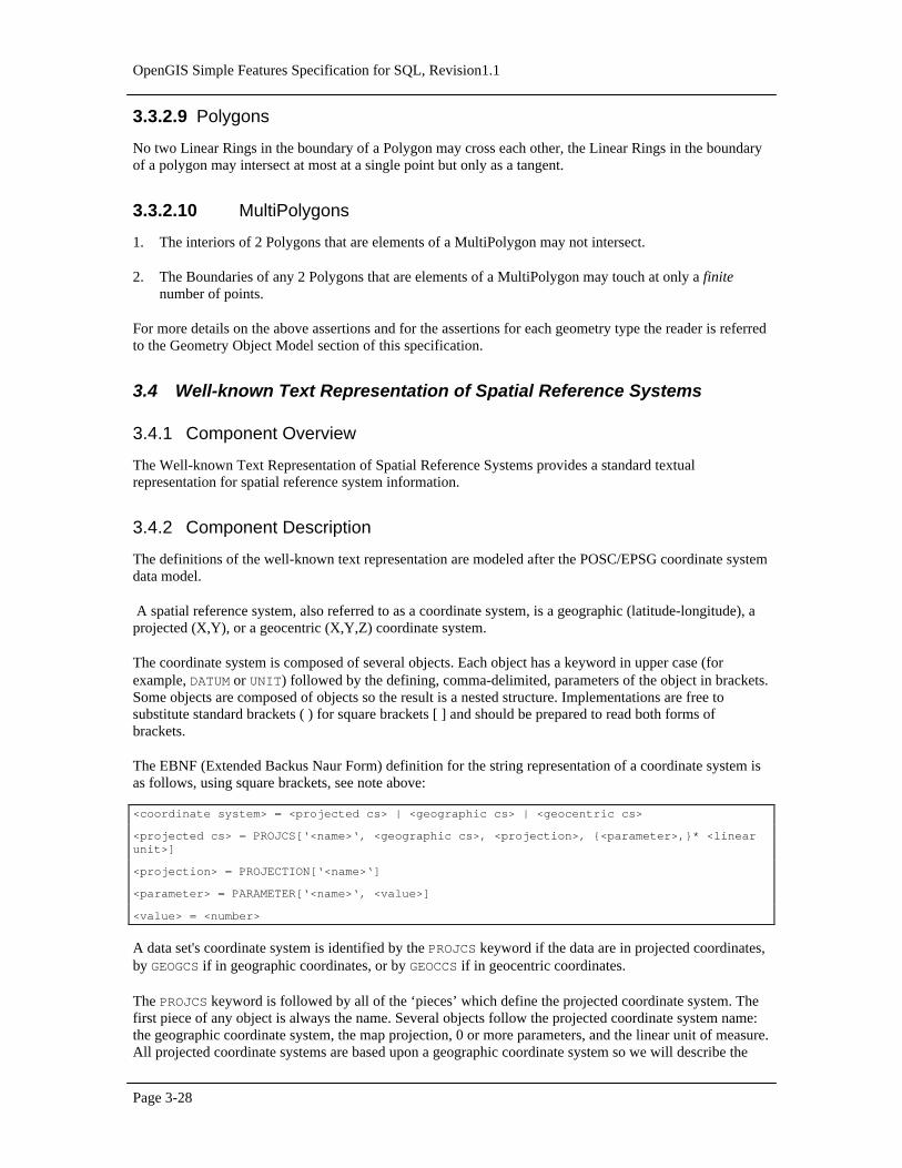
OpenGIS Simple Features Specification for SQL, Revision1.1
Page 3-28
3.3.2.9 Polygons
No two Linear Rings in the boundary of a Polygon may cross each other, the Linear Rings in the boundaryof a polygon may intersect at most at a single point but only as a tangent.
3.3.2.10 MultiPolygons
1. The interiors of 2 Polygons that are elements of a MultiPolygon may not intersect.
2. The Boundaries of any 2 Polygons that are elements of a MultiPolygon may touch at only a finitenumber of points.
For more details on the above assertions and for the assertions for each geometry type the reader is referredto the Geometry Object Model section of this specification.
3.4 Well-known Text Representation of Spatial Reference Systems
3.4.1 Component Overview
The Well-known Text Representation of Spatial Reference Systems provides a standard textualrepresentation for spatial reference system information.
3.4.2 Component Description
The definitions of the well-known text representation are modeled after the POSC/EPSG coordinate systemdata model.
A spatial reference system, also referred to as a coordinate system, is a geographic (latitude-longitude), aprojected (X,Y), or a geocentric (X,Y,Z) coordinate system.
The coordinate system is composed of several objects. Each object has a keyword in upper case (forexample, DATUM or UNIT) followed by the defining, comma-delimited, parameters of the object in brackets.Some objects are composed of objects so the result is a nested structure. Implementations are free tosubstitute standard brackets ( ) for square brackets [ ] and should be prepared to read both forms ofbrackets.
The EBNF (Extended Backus Naur Form) definition for the string representation of a coordinate system isas follows, using square brackets, see note above:
<coordinate system> = <projected cs> | <geographic cs> | <geocentric cs>
<projected cs> = PROJCS[‘<name>‘, <geographic cs>, <projection>, {<parameter>,}* <linearunit>]
<projection> = PROJECTION[‘<name>‘]
<parameter> = PARAMETER[‘<name>‘, <value>]
<value> = <number>
A data set's coordinate system is identified by the PROJCS keyword if the data are in projected coordinates,by GEOGCS if in geographic coordinates, or by GEOCCS if in geocentric coordinates.
The PROJCS keyword is followed by all of the ‘pieces’ which define the projected coordinate system. Thefirst piece of any object is always the name. Several objects follow the projected coordinate system name:the geographic coordinate system, the map projection, 0 or more parameters, and the linear unit of measure.All projected coordinate systems are based upon a geographic coordinate system so we will describe the

Chapter 3 Component Specifications
Page 3-29
pieces specific to a projected coordinate system first. As an example, UTM zone 10N on the NAD83 datumis defined as:
PROJCS[‘NAD_1983_UTM_Zone_10N’,<geographic cs>,PROJECTION[‘Transverse_Mercator’],PARAMETER[‘False_Easting’,500000.0],PARAMETER[‘False_Northing’,0.0],PARAMETER[‘Central_Meridian’,-123.0],PARAMETER[‘Scale_Factor’,0.9996],PARAMETER[‘Latitude_of_Origin’,0.0],UNIT[‘Meter’,1.0]]
The name and several objects define the geographic coordinate system object in turn: the datum, the primemeridian, and the angular unit of measure.
<geographic cs> = GEOGCS[‘<name>‘, <datum>, <prime meridian>, <angular unit>]
<datum> = DATUM[‘<name>‘, <spheroid>]
<spheroid> = SPHEROID[‘<name>‘, <semi-major axis>, <inverse flattening>]
<semi-major axis> = <number> NOTE: semi-major axis is measured in meters and must be > 0.
<inverse flattening> = <number>
<prime meridian> = PRIMEM[‘<name>‘, <longitude>]
<longitude> = <number>
The geographic coordinate system string for UTM zone 10 on NAD83 is
GEOGCS[‘GCS_North_American_1983’,DATUM[‘D_North_American_1983’,SPHEROID[‘GRS_1980’,6378137,298.257222101]],PRIMEM[‘Greenwich’,0],UNIT[‘Degree’,0.0174532925199433]]
The UNIT object can represent angular or linear unit of measures.
<angular unit> = <unit>
<linear unit> = <unit>
<unit> = UNIT[‘<name>‘, <conversion factor>]
<conversion factor> = <number>
<conversion factor> specifies number of meters (for a linear unit) or number of radians (for anangular unit) per unit and must be greater than zero.
So the full string representation of UTM Zone 10N is
PROJCS[‘NAD_1983_UTM_Zone_10N’,GEOGCS[‘GCS_North_American_1983’,DATUM[ ‘D_North_American_1983’,SPHEROID[‘GRS_1980’,6378137,298.257222101]],PRIMEM[‘Greenwich’,0],UNIT[‘Degree’,0.0174532925199433]],PROJECTION[‘Transverse_Mercator’],PARAMETER[‘False_Easting’,500000.0],PARAMETER[‘False_Northing’,0.0],PARAMETER[‘Central_Meridian’,-123.0],PARAMETER[‘Scale_Factor’,0.9996],PARAMETER[‘Latitude_of_Origin’,0.0],UNIT[‘Meter’,1.0]]
A geocentric coordinate system is quite similar to a geographic coordinate system. It is represented by
<geocentric cs> = GEOCCS[‘<name>‘, <datum>, <prime meridian>, <linear unit>]

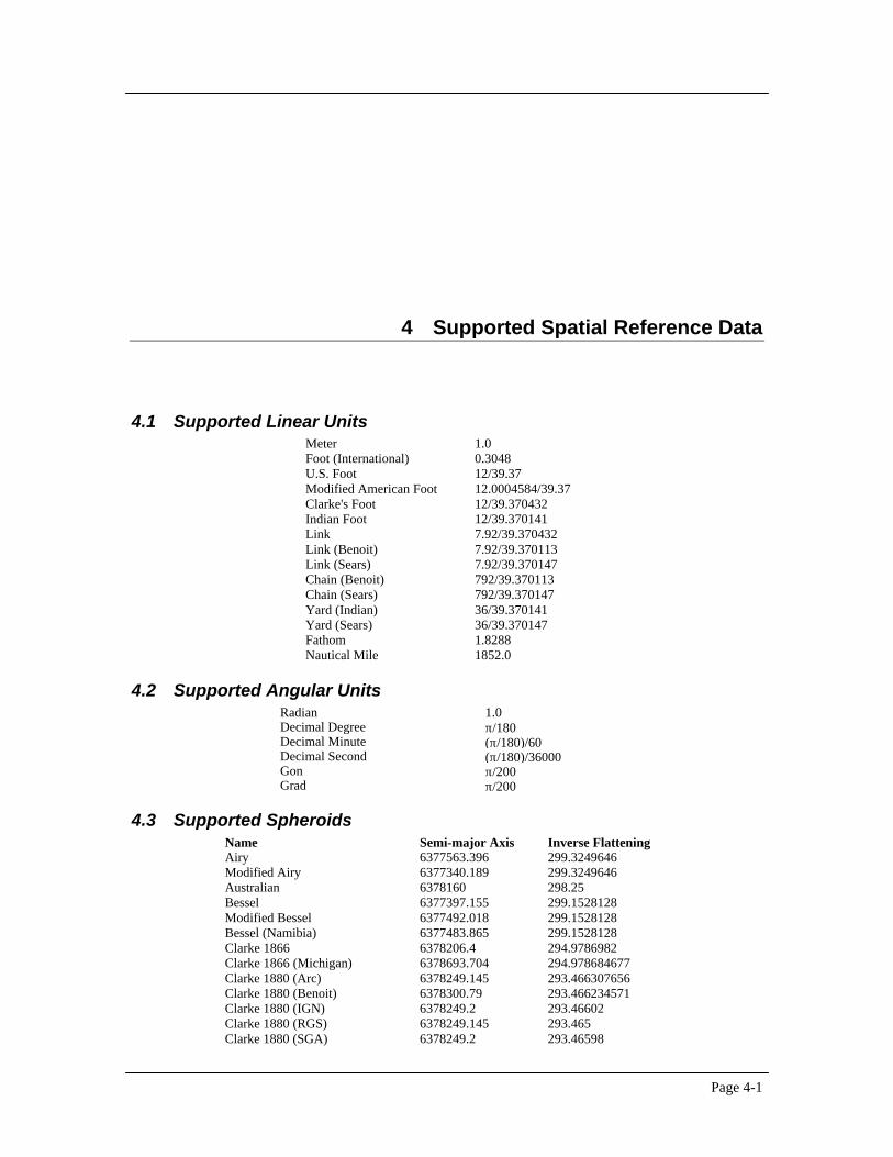
Page 4-1
4 Supported Spatial Reference Data
4.1 Supported Linear UnitsMeter 1.0Foot (International) 0.3048U.S. Foot 12/39.37Modified American Foot 12.0004584/39.37Clarke's Foot 12/39.370432Indian Foot 12/39.370141Link 7.92/39.370432Link (Benoit) 7.92/39.370113Link (Sears) 7.92/39.370147Chain (Benoit) 792/39.370113Chain (Sears) 792/39.370147Yard (Indian) 36/39.370141Yard (Sears) 36/39.370147Fathom 1.8288Nautical Mile 1852.0
4.2 Supported Angular UnitsRadian 1.0Decimal Degree π/180Decimal Minute (π/180)/60Decimal Second (π/180)/36000Gon π/200Grad π/200
4.3 Supported SpheroidsName Semi-major Axis Inverse FlatteningAiry 6377563.396 299.3249646Modified Airy 6377340.189 299.3249646Australian 6378160 298.25Bessel 6377397.155 299.1528128Modified Bessel 6377492.018 299.1528128Bessel (Namibia) 6377483.865 299.1528128Clarke 1866 6378206.4 294.9786982Clarke 1866 (Michigan) 6378693.704 294.978684677Clarke 1880 (Arc) 6378249.145 293.466307656Clarke 1880 (Benoit) 6378300.79 293.466234571Clarke 1880 (IGN) 6378249.2 293.46602Clarke 1880 (RGS) 6378249.145 293.465Clarke 1880 (SGA) 6378249.2 293.46598

OpenGIS Simple Features Specification for SQL, Revision1.1
Page 4-2
Everest 1830 6377276.345 300.8017Everest 1975 6377301.243 300.8017Everest (Sarawak and Sabah) 6377298.556 300.8017Modified Everest 1948 6377304.063 300.8017GEM10C 6378137 298.257222101GRS 1980 6378137 298.257222101Helmert 1906 6378200 298.3International 1924 6378388 297.0Krasovsky 6378245 298.3NWL9D 6378145 298.25OSU_86F 6378136.2 298.25722OSU_91A 6378136.3 298.25722Plessis 1817 6376523 308.64Sphere (radius = 1.0) 1 0Sphere (radius = 6371000 m) 6371000 0Struve 1860 6378297 294.73War Office 6378300.583 296WGS 1984 6378137 298.257223563
4.4 Supported Geodetic DatumsAdindan LisbonAfgooye Loma QuintanaAgadez LomeAustralian Geodetic Datum 1966 Luzon 1911Australian Geodetic Datum 1984 Mahe 1971Ain el Abd 1970 MakassarAmersfoort Malongo 1987Aratu ManocaArc 1950 MassawaArc 1960 MerchichAncienne Triangulation Francaise Militar-Geographische InstituteBarbados MhastBatavia MinnaBeduaram Monte MarioBeijing 1954 M'poralokoReseau National Belge 1950 NAD MichiganReseau National Belge 1972 North American Datum 1927Bermuda 1957 North American Datum 1983Bern 1898 Nahrwan 1967Bern 1938 Naparima 1972Bogota Nord de GuerreBukit Rimpah NGO 1948Camacupa Nord Sahara 1959Campo Inchauspe NSWC 9Z-2Cape Nouvelle Triangulation FrancaiseCarthage New Zealand Geodetic Datum 1949Chua OS (SN) 1980Conakry 1905 OSGB 1936Corrego Alegre OSGB 1970 (SN)Cote d'Ivoire Padang 1884Datum 73 Palestine 1923Deir ez Zor Pointe NoireDeutsche Hauptdreiecksnetz Provisional South American Datum 1956Douala Pulkovo 1942European Datum 1950 QatarEuropean Datum 1987 Qatar 1948Egypt 1907 QornoqEuropean Reference System 1989 RT38Fahud South American Datum 1969Gandajika 1970 Sapper Hill 1943Garoua Schwarzeck

Geocentric Datum of Australia 1994 SegoraGuyane Francaise SerindungHerat North Stockholm 1938Hito XVIII 1963 SudanHu Tzu Shan Tananarive 1925Hungarian Datum 1972 Timbalai 1948Indian 1954 TM65Indian 1975 TM75Indonesian Datum 1974 TokyoJamaica 1875 Trinidad 1903Jamaica 1969 Trucial Coast 1948Kalianpur Voirol 1875Kandawala Voirol Unifie 1960Kertau WGS 1972Kuwait Oil Company WGS 1972 Transit Broadcast EphemerisLa Canoa WGS 1984Lake YacareLeigon YoffLiberia 1964 Zanderij
4.5 Supported Prime MeridiansGreenwich 0° 0' 0"Bern 7° 26' 22.5" EBogota 74° 4' 51.3" WBrussels 4° 22' 4.71" EFerro 17° 40' 0" WJakarta 106° 48' 27.79" ELisbon 9° 7' 54.862" WMadrid 3° 41' 16.58" WParis 2° 20' 14.025"ERome 12° 27' 8.4" EStockholm 18° 3' 29" E
4.6 Supported Map ProjectionsCylindrical Projections Conic ProjectionsCassini Albers conic equal-areaGauss-Kruger Lambert conformal conicMercator Azimuthal or Planar ProjectionsOblique Mercator (Hotine) Polar StereographicTransverse Mercator Stereographic
4.7 Map Projection Parameterscentral_meridian the line of longitude chosen as the origin of x-coordinates.scale_factor used generally to reduce the amount of distortion in a map projection.standard_parallel_1 a line of latitude that has no distortion generally. Also used for ‘latitude of
true scale.’standard_parallel_2 a line of latitude that has no distortion generally.longitude_of_center the longitude which defines the center point of the map projection.latitude_of_center the latitude which defines the center point of the map projection.latitude_of_origin the latitude chosen as the origin of y-coordinates.false_easting added to x-coordinates. Used to give positive values.false_northing added to y-coordinates. Used to give positive values.azimuth the angle east of north which defines the center line of an oblique
projection.longitude_of_point_1 the longitude of the first point needed for a map projection.latitude_of_point_1 the latitude of the first point needed for a map projection.longitude_of_point_2 the longitude of the second point needed for a map projection.latitude_of_point_2 the latitude of the second point needed for a map projection.


Page 5-1
5 References
1. The OpenGIS Abstract Specification: An Object Model for Interoperable Geoprocessing, Revision 1,OpenGIS Consortium, Inc, OpenGIS Project Document Number 96-015R1, 1996.
2. OpenGIS Project Document 96-025: Geodetic Reference Systems, OpenGIS Consortium, Inc, October14, 1996.
3. POSC (Petrotechnical Open Software Consortium) Epicentre Model V2.1,fttp://posc.org/public/geodetic, July 1995.
4. Clementini, Eliseo, Di Felice, P., van Oostrom, p., A Small Set of Formal Topological RelationshipsSuitable for End-User Interaction, in D. Abel and B. C. Ooi (Ed.), Advances in Spatial Databases—Third International Symposium. SSD ’93. LNCS 692. Pp. 277-295. Springer-Verlag. Singapore(1993).
5. Clementini E. and Di Felice P., A Comparison of Methods for Representing TopologicalRelationships, Information Sciences 80, 1-34, 1994.
6. Clementini, Eliseo, Di Felice, P., A Model for Representing Topological Relationships BetweenComplex Geometric Features in Spatial Databases, Information Sciences 90 (1-4):121-136 , 1996.
7. Clementini E., Di Felice P and Califano, G. Composite Regions in Topological Queries, InformationSystems, v 20, no 6, pp 33-48, 1995.
8. Egenhofer, M.F. and Franzosa, Point Set Topological Spatial Relations, International Journal ofGeographical Information Systems, vol 5, no 2, 161-174, 1991.
9. Egenhofer, M.J., Clementini, E. and Di Felice, P., Topological relations between regions with holes,International Journal of Geographical Information Systems, vol 8, no 2, pp 129—142, 1994.
10. Egenhofer, M.J. and Herring, J., A mathematical framework for the definition of topologicalrelationships. Proceedings of the Fourth International Symposium on Spatial Data Handling,Columbus, Ohi, pp. 803-813.
11. Egenhofer M.J. and Herring, J., Categorizing binary topological relationships between regions, linesand points in geographic databases, Tech. Report., Department of Surveying Engineering, Universityof Maine, Orono, ME 1991.

OpenGIS Simple Features Specification for SQL, Revision1.1
Page 5-2
12. Egenhofer. M.J. and Sharma, J., Topological Relations between regions in ℜ2 and Ζ2, Advances inSpatial Databases—Third International Symposium, SSD ’93, vol. 692, Lecture Notes in ComputerScience, pp. 36-52, Springer Verlag, Singapore (1993).
13. Worboys, M.F. and Bofakos, P. A Canonical model for a class of areal spatial objects, Advances inSpatial Databases—Third International Symposium, SSD ’93, vol. 692, Lecture Notes in ComputerScience, pp. 36-52, Springer Verlag, Singapore (1993).
14. Worboys, M.F. A generic model for planar geographical objects, International Journal of GeographicalInformation Systems, 1992, vol 6, no 5, 353-372.
15. http://www.omg.org/corba/sectrans.htm : CORBAservices : Common Object Services Specification,Ch 8. Externalization Service Specification, OMG.
16. http://www.microsoft.com/oledev : Distributed Component Object Model Protocol Specification—DCOM 1.0, Microsoft Corporation.