simatic s7-300 programmable controller module specifications · s7-300 programmable controller...
TRANSCRIPT

Preface, Contents
General Technical Specifications1
Power Supply Modules2
Digital Modules3
Analog Modules4
Other Signal Modules5
Interface Modules6
RS 485 Repeater7
SIMATIC TOP connect andSIMATIC TOP connect TPA
8
Appendix
Parameter Sets for SignalModules
ADiagnostics Data of SignalModules
B
Dimension DrawingsC
Spare Parts and Accessories forS7-300 Modules
DGuidelines for HandlingElectrostatic Sensitive Devices(ESD)
E
List of AbbreviationsF
Glossary, Index
Edition 11/2002A5E00105505-02
S7-300 Programmable ControllerModule Specifications
Reference Manual
SIMATIC
This manual is part of the documentation packagewith the order numbers:Programmable Controller S7-300:6ES7398-8FA10-8BA0
ET 200M Distributed I/O Device:6ES7153-1AA00-8BA0

AChapter
Index-2S7-300 Programmable Controller Module Specifications
A5E00105505-02
!Danger
indicates that death, severe personal injury or substantial property damage will result if proper precautionsare not taken.
!Warning
indicates that death, severe personal injury or substantial property damage can result if properprecautions are not taken.
!Caution
indicates that minor personal injury can result if proper precautions are not taken.
Caution
indicates that property damage can result if proper precautions are not taken.
Notice
draws your attention to particularly important information on the product, handling the product, or to aparticular part of the documentation.
Qualified PersonnelOnly qualified personnel should be allowed to install and work on this equipment. Qualified persons aredefined as persons who are authorized to commission, to ground and to tag circuits, equipment, andsystems in accordance with established safety practices and standards.
Correct UsageNote the following:
!Warning
This device and its components may only be used for the applications described in the catalog or thetechnical description, and only in connection with devices or components from other manufacturers whichhave been approved or recommended by Siemens.
This product can only function correctly and safely if it is transported, stored, set up, and installedcorrectly, and operated and maintained as recommended.
TrademarksSIMATIC, SIMATIC HMI and SIMATIC NET are registered trademarks of SIEMENS AG.
Third parties using for their own purposes any other names in this document which refer to trademarksmight infringe upon the rights of the trademark owners.
Safety GuidelinesThis manual contains notices intended to ensure personal safety, as well as to protect the products andconnected equipment against damage. These notices are highlighted by the symbols shown below andgraded according to severity by the following texts:
We have checked the contents of this manual for agreementwith the hardware and software described. Since deviationscannot be precluded entirely, we cannot guarantee fullagreement. However, the data in this manual are reviewedregularly and any necessary corrections included insubsequent editions. Suggestions for improvement arewelcomed.
Disclaim of LiabilityCopyright Siemens AG 1998–2002 All rights reserved
The reproduction, transmission or use of this document or itscontents is not permitted without express written authority.Offenders will be liable for damages. All rights, including rightscreated by patent grant or registration of a utility model ordesign, are reserved.
Siemens AGBereich Automatisierungs- und AntriebstechnikGeschaeftsgebiet Industrie-AutomatisierungssystemePostfach 4848, D- 90327 Nuernberg
Siemens AG 1998–2002Technical data subject to change.
Siemens Aktiengesellschaft A5E00105505-02

iiiS7-300 Programmable Controller Module SpecificationsA5E00105505-02
Preface
Purpose of the manual
The information contained in this manual will enable you to look up operatoractions, function descriptions and the technical specifications of the signalmodules, power supply modules and interface modules of the S7-300.
How to configure, assemble and wire these modules in an S7-300 or ET 200Msystem is described in the installation manuals for each system.
Required basic knowledge
To understand this manual, it is necessary to have a general knowledge ofautomation and programmable logic controllers.
Scope of this manual
The present documentation package contains reference manuals for all themodules current at the time the manuals were published.
We reserve the right to enclose a product information leaflet containing up-to-dateinformation on the module with new modules and modules with a new productversion.
Changes compared with the previous version
Compared to the previous version, of the ”Module Data” reference manual, thefollowing chapters and appendices have been thoroughly revised and new modulesadded, as necessary:
Preface
Chapter 1 ”General Technical Specifications”
Chapter 3 ”Digital Modules”,
Chapter 4 ”Analog Modules”
Appendix A ”Signal Module Parameter Sets”
Glossary
Note: The previous version of this ”Module Data” reference manual can berecognized by the number in the footer: A5E00105505-01.
The current number is: A5E00105505-02.

Preface
ivS7-300 Programmable Controller Module Specifications
A5E00105505-02
Approbations
Refer to Section 1.1 Standards and approvals.
CE Approval
Refer to Section 1.1 Standards and approvals.
Identification for Australia (C-Tick-Mark)
Refer to Section 1.1 Standards and approvals.
Standards
Refer to Section 1.1 Standards and approvals.
Preface
vS7-300 Programmable Controller Module SpecificationsA5E00105505-02
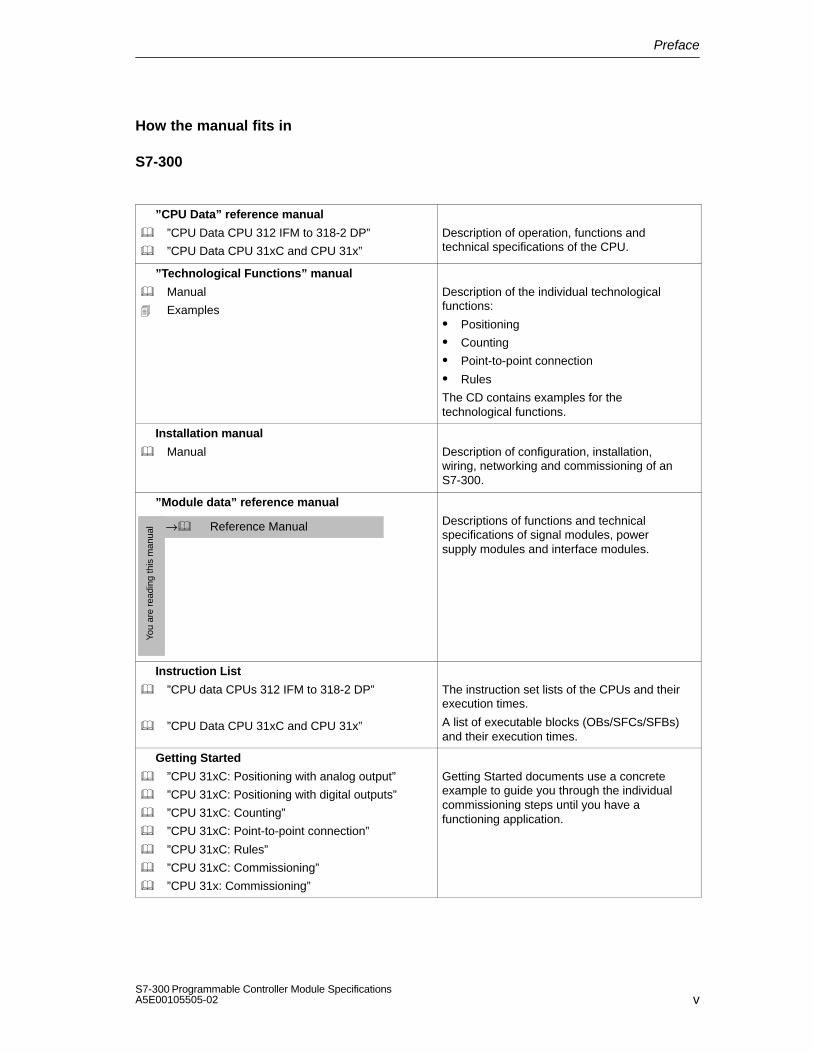
How the manual fits in
S7-300
”CPU Data” reference manual
”CPU Data CPU 312 IFM to 318-2 DP”
”CPU Data CPU 31xC and CPU 31x”
Description of operation, functions andtechnical specifications of the CPU.
”Technological Functions” manual
Manual
Examples
Description of the individual technologicalfunctions:
Positioning
Counting
Point-to-point connection
Rules
The CD contains examples for the technological functions.
Installation manual
Manual Description of configuration, installation, wiring, networking and commissioning of anS7-300.
”Module data” reference manual
You
are
read
ing
this
man
ual Reference Manual→ Descriptions of functions and technical
specifications of signal modules, power supply modules and interface modules.
Instruction List
”CPU data CPUs 312 IFM to 318-2 DP”
”CPU Data CPU 31xC and CPU 31x”
The instruction set lists of the CPUs and theirexecution times.
A list of executable blocks (OBs/SFCs/SFBs)and their execution times.
Getting Started
”CPU 31xC: Positioning with analog output”
”CPU 31xC: Positioning with digital outputs”
”CPU 31xC: Counting”
”CPU 31xC: Point-to-point connection”
”CPU 31xC: Rules”
”CPU 31xC: Commissioning”
”CPU 31x: Commissioning”
Getting Started documents use a concrete example to guide you through the individualcommissioning steps until you have a functioning application.

Preface
viS7-300 Programmable Controller Module Specifications
A5E00105505-02
ET 200M
”Distributed Peripheral” manual
”Manual” Description of configuration, assembly, wiring.
Reference Manual
”Signal modules for process automation”
”Reference Manual”
Description of use in process automation,parameterization with SIMATIC PDM, digitalinput modules, digital output modules.
”Module data” reference manual
You
are
read
ing
this
man
ual Reference Manual→ Descriptions of functions and technical
specifications of signal modules, power supply modules and interface modules.
Navigation
To help you find special information quickly, the manual contains the followingaccess aids:
At the start of the manual you will find a complete table of contents and a list ofthe diagrams and tables that appear in the manual.
An overview of the contents of each section is provided in the left column oneach page of each chapter.
You will find a glossary in the appendix at the end of the manual. The glossarycontains definitions of the main technical terms used in the manual.
At the end of the manual you will find a comprehensive index which gives youfast access to the information you need.
Recycling and disposal
Because of its low-emission equipment, it is possible to recycle the S7-300. Forecologically harmless recycling and disposal of your old device, contact acertificated disposal service for electronic scrap.

Preface
viiS7-300 Programmable Controller Module SpecificationsA5E00105505-02
Additional support
Please contact your local Siemens representative if you have any queries aboutthe products described in this manual.
http://www.ad.siemens.com/automation/partner
Training center
We offer a range of relevant courses to help you to get started with the SIMATICS7 programmable controller. Please contact your local training center or the centraltraining center in Nuremberg, D 90327 Germany. Phone: +49 (911) 895-3200.
Internet: http://www.sitrain.com

Preface
viiiS7-300 Programmable Controller Module Specifications
A5E00105505-02
A&D Technical Support
Contact at any time of the day throughout the world:
Johnson City
Nuremberg
Peking
Technical Support
Worldwide (Nuremberg)
Technical Support
Loc. time: 0:00 to 24:00 / 365 days
Phone: +49 (0) 180 5050-222
Fax: +49 (0) 180 5050-223
E-mail: [email protected]
GMT: +1:00
Europe / Africa (Nuremberg)
Authorization
Loc. time: Mon. through Fri. 8 AM to 5 PM
Phone: +49 (0) 180 5050-222
Fax: +49 (0) 180 5050-223
E-mail: [email protected]
GMT: +1:00
America (Johnson City)
Technical Support andAuthorizationLoc. time: Mon. through Fri.
8 AM to 5 PM
Phone: +1 (0) 770 740 3505
Fax: +1 (0) 779 740 3699
E-mail: [email protected]
GMT: -5:00
Asia and Australia (Peking)
Technical Support andAuthorizationLoc. time: Mon. through Fri.
8.30 AM to 5.30 PM
Phone: +86 10 64 75 75 75
Fax: +86 10 64 74 74 74
E-mail: [email protected]
GMT: +8:00
Technical Support and Authorization generally speak German and English.

Preface
ixS7-300 Programmable Controller Module SpecificationsA5E00105505-02
Service & Support on the Internet
In addition to our documentation products and services, all our knowledge isavailable to you on the Internet.
http://www.siemens.com/automation/service&support
Available over the Internet are:
the newsletter, constantly bringing you the latest information about ourproducts.
the right documents for you, thanks to our Search in Service & Support.
a forum in which users and specialists can swap experiences world-wide.
your local point of contact for Automation & Drives in our Contacts Database
information about local service, repairs, spare parts. Much more is available toyou under ”Achievements”.

Preface
xS7-300 Programmable Controller Module Specifications
A5E00105505-02

xiS7-300 Programmable Controller Module SpecificationsA5E00105505-02
Contents
Preface
1 General Technical Specifications
1.1 Standards and Approvals 1-2. . . . . . . . . . . . . . . . . . . . . . . . . . . . . . . . . . . . . . . . .
1.2 Electromagnetic Compatibility 1-6. . . . . . . . . . . . . . . . . . . . . . . . . . . . . . . . . . . . .
1.3 Shipping and Storage Conditions for Modules and Backup Batteries 1-8. . . .
1.4 Mechanical and Climatic Environmental Conditions for Operating S7-300s 1-9. . . . . . . . . . . . . . . . . . . . . . . . . . . . . . . . . . . . . . . . . . . . . .
1.5 Information on Insulation Tests, Protection Class and Degree of Protection 1-12. . . . . . . . . . . . . . . . . . . . . . . . . . . . . . . . . . . . . . . . . . . . . . . . . . . .
1.6 Rated Voltages of the S7-300 1-13. . . . . . . . . . . . . . . . . . . . . . . . . . . . . . . . . . . . .
1.7 SIMATIC Outdoor Modules 1-14. . . . . . . . . . . . . . . . . . . . . . . . . . . . . . . . . . . . . . .
1.8 Mechanical and Climatic Environmental Conditions for Operating SIMATIC Outdoor Modules 1-16. . . . . . . . . . . . . . . . . . . . . . . . . . . . . . . . . . . . . . .
1.9 Use of the ET 200M / S7-300 in a Zone 2 Potentially Explosive Area 1-17. . .
2 Power Supply Modules
2.1 Power Supply Module PS 305; 2 A; (6ES7 305-1BA80-0AA0) 2-2. . . . . . . . .
2.2 Power Supply Module PS 307; 2 A; (6ES7 307-1BA00-0AA0) 2-6. . . . . . . . . . . . . . . . . . . . . . . . . . . . . . . . . . . . . . . . .
2.3 Power Supply Module PS 307; 5 A; (6ES7 307-1EAx0-0AA0) 2-10. . . . . . . . .
2.4 Power Supply Module PS 307; 10 A; (6ES7 307-1KA00-0AA0) 2-15. . . . . . . .
3 Digital Modules
3.1 Module Overview 3-4. . . . . . . . . . . . . . . . . . . . . . . . . . . . . . . . . . . . . . . . . . . . . . . .
3.2 Sequence of Steps from Choosing to Commissioning the Digital Module 3-10
3.3 Digital Module Parameter Assignment 3-11. . . . . . . . . . . . . . . . . . . . . . . . . . . . . .
3.4 Diagnostics of the Digital Modules 3-12. . . . . . . . . . . . . . . . . . . . . . . . . . . . . . . . .
3.5 Digital Input Module SM 321; DI 3224 VDC;(6ES7 321-1BLx0-0AA0) 3-13. . . . . . . . . . . . . . . . . . . . . . . . . . . . . . . . . . . . . . . . .
3.6 Digital Input Module SM 321; DI 32120 VAC; (6ES7 321-1EL00-0AA0) 3-16. . . . . . . . . . . . . . . . . . . . . . . . . . . . . . . . . . . . . . . . .
3.7 Digital Input Module SM 321; DI 1624 VDC; (6ES7 321-1BHx2-0AA0) 3-18. . . . . . . . . . . . . . . . . . . . . . . . . . . . . . . . . . . . . . . . .

Contents
xiiS7-300 Programmable Controller Module Specifications
A5E00105505-02
3.8 Digital Input Module SM 321; DI 1624 VDC High Speed; (6ES7 321-1BH10-0AA0) 3-21. . . . . . . . . . . . . . .
3.9 Digital Input Module SM 321; DI 1624 VDC; with Hardware and Diagnostic interrupts; (6ES7 321-7BHx0-0AB0) 3-23. . . . . . . . . . . . . . . . . . . . . .
3.9.1 Assigning Parameters to the SM 321; DI 1624 VDC 3-26. . . . . . . . . . . . . . . . 3.9.2 Behavior and Diagnostics of the SM 321; DI 1624 VDC 3-28. . . . . . . . . . . . . 3.9.3 Interrupts of the SM 321; DI 1624 VDC 3-31. . . . . . . . . . . . . . . . . . . . . . . . . . .
3.10 Digital Input Module SM 321; DI 16DC 24 V; Source Input; (6ES7 321-1BH50-0AA0) 3-33. . . . . . . . . . . . . . . . . . . . . . . . . . . .
3.11 Digital Input Module SM 321; DI 16UC 24/48 V; (6ES7 321-1CH00-0AA0) 3-35. . . . . . . . . . . . . . . . . . . . . . . . . . . . . . . . . . . . . . . . .
3.12 Digital Input Module SM 321; DI 1648-125 VDC; (6ES7 321-1CH80-0AA0) 3-37. . . . . . . . . . . . . . . . . . . . . . . . . . . . . . . . . . . . . . . . .
3.13 Digital Input Module SM 321; DI 16AC 120/230 V (6ES7 321-1FH00-0AA0) 3-39. . . . . . . . . . . . . . . . . . . . . . . . . . . . . . . . . . . . . . . . .
3.14 Digital Input Module SM 321; DI 8120/230 VAC; (6ES7 321-1FFx1-0AA0) 3-41. . . . . . . . . . . . . . . . . . . . . . . . . . . . . . . . . . . . . . . . .
3.15 Digital Input Module SM 321; DI 8120/230 VAC ISOL (6ES7 321-1FF10-0AA0) 3-43. . . . . . . . . . . . . . . . . .
3.16 Digital Output Module SM 322; DO 3224 VDC/ 0.5 A; (6ES7 322-1BL00-0AA0) 3-45. . . . . . . . . . . . . . . . . . .
3.17 Digital Output Module SM 322; DO 32120 VAC/1.0 A; (6ES7 322-1EL00-0AA0) 3-48. . . . . . . . . . . . . . . . . . . . . . . . . . . . . . . . . . . . . . . . .
3.18 Digital Output Module SM 322; DO 1624 VDC/ 0.5 A; (6ES7 322-1BHx1-0AA0) 3-52. . . . . . . . . . . . . . . . . . .
3.19 Digital Output Module SM 322; DO 1624 VDC/0.5 A High Speed; (6ES7 322-1BH10-0AA0) 3-55. . . . . . . . . . . . . . . . . . . . . . . . . . . . . . . . . . . . . . . . .
3.20 Digital Output Module SM 322; DO 1624/48 VUC; (6ES7 322-5GH00-0AB0) 3-58. . . . . . . . . . . . . . . . . . . . . . . . . . . . . . . . . . . . . . . .
3.21 Digital Output Module SM 322; DO 16120/230 VAC/1 A: (6ES7 322-1FH00-0AA0) 3-64. . . . . . . . . . . . . . . . .
3.22 Digital Output Module SM 322; DO 824 VDC/2 A; (6ES7 322-1BF01-0AA0) 3-67. . . . . . . . . . . . . . . . . . . . . . . . . . . . . . . . . . . . . . . . .
3.23 Digital Output Module SM 322; DO 824 VDC/ 0.5 A; with Diagnostic Interrupt; (6ES7 322-8BFx0-0AB0) 3-70. . . . . . . . . . . . . . . . . . . . . . .
3.23.1 Assigning Parameters to the SM 322; DO 824 VDC/0.5 A 3-75. . . . . . . . . . . 3.23.2 Behavior and Diagnostics of the SM 322; DO 824 VDC/0.5 A 3-76. . . . . . . 3.23.3 Interrupts of the SM 322; DO 824 VDC/0.5 A 3-79. . . . . . . . . . . . . . . . . . . . . .
3.24 Digital Output Module SM 322; DO 848-125 VDC/1.5 A; (6ES7 322-1CF80-0AA0) 3-80. . . . . . . . . . . . . . . . . . . . . . . . . . . . . . . . . . . . . . . . .

Contents
xiiiS7-300 Programmable Controller Module SpecificationsA5E00105505-02
3.25 Digital Output Module SM 322; DO 8120/230 VAC/2 A; (6ES7 322-1FFx1-0AA0) 3-83. . . . . . . . . . . . . . . . . . . . . . . . . . . . . . . . . . . . . . . . .
3.26 Digital Output Module SM 322; DO 8120/230 VAC/2 A ISOL (6ES7 322-5FF00-0AB0) 3-86. . . . . . . . . . . . . . . . . . . . . . . . . . . . . . . . . . . . . . . . .
3.27 Relay Output Module SM 322; DO 16Rel. 120/230 VAC; (6ES7 322-1HH01-0AA0) 3-92. . . . . . . . . . . . . . . . . . . . . . . . . . . . . . . . . . . . . . . . .
3.28 Relay Output Module SM 322; DO 8Rel. 230 VAC; (6ES7 322-1HF01-0AA0) 3-95. . . . . . . . . . . . . . . . . . . . . . . . . . . . . . . . . . . . . . . . .
3.29 Relay Output Module SM 322; DO 8Rel. 230 VAC/5A; (6ES7 322-5HF00-0AB0) 3-98. . . . . . . . . . . . . . . . . .
3.29.1 SM 322; DO 8Rel. 230 VAC/5A parameterization 3-102. . . . . . . . . . . . . . . . . . 3.29.2 Behavior and Diagnostics of the SM 322; DO 8230 VDC/0.5 A 3-103. . . . . .
3.30 Relay Output Module SM 322; DO 8Rel. 230 VAC/5 A; (6ES7 322-1HFx0-0AA0) 3-105. . . . . . . . . . . . . . . . . . . . . . . . . . . . . . . . . . . . . . . . .
3.31 Digital Input/Output Module SM 323; DI 16/DO 1624 VDC/0.5 A; (6ES7 323-1BL00-0AA0) 3-110. . . . . . . . . . . . . . . . . . . . . . . . . . . . . . . . . . . . . . . . .
3.32 Digital Input/Output Module SM 323; DI 8/DO 824 VDC/0.5 A;(6ES7 323-1BHx1-0AA0) 3-114. . . . . . . . . . . . . . . . . . . . . . . . . . . . . . . . . . . . . . . . .
4 Analog Modules
4.1 Module Overview 4-3. . . . . . . . . . . . . . . . . . . . . . . . . . . . . . . . . . . . . . . . . . . . . . . .
4.2 Sequence of Steps from Choosing to Commissioning the Module 4-8. . . . . .
4.3 Analog Value Representation 4-10. . . . . . . . . . . . . . . . . . . . . . . . . . . . . . . . . . . . . 4.3.1 Analog Value Representation for Analog Input Channels 4-11. . . . . . . . . . . . . . 4.3.2 Analog Value Representation for Analog Output Channels 4-26. . . . . . . . . . . .
4.4 Setting the Measuring Method and Measuring Ranges of Analog InputChannels 4-31. . . . . . . . . . . . . . . . . . . . . . . . . . . . . . . . . . . . . . . . . . . . . . . . . . . . . . .
4.5 Behavior of the Analog Modules 4-34. . . . . . . . . . . . . . . . . . . . . . . . . . . . . . . . . . . 4.5.1 Effect of Supply Voltage and Operating Mode 4-34. . . . . . . . . . . . . . . . . . . . . . . 4.5.2 Effect of Range of Values of the Analog Values 4-36. . . . . . . . . . . . . . . . . . . . . . 4.5.3 Effect of Operational Limit and Basic Error Limit 4-38. . . . . . . . . . . . . . . . . . . . .
4.6 Conversion, Cycle, Setting and Response Time of Analog Modules 4-39. . . .
4.7 Analog Module Parameter Assignment 4-43. . . . . . . . . . . . . . . . . . . . . . . . . . . . . 4.7.1 Parameters of the Analog Input Modules 4-44. . . . . . . . . . . . . . . . . . . . . . . . . . . 4.7.2 Parameters of the Analog Output Modules 4-47. . . . . . . . . . . . . . . . . . . . . . . . . . 4.7.3 Parameters of the Analog Input/Output Modules 4-48. . . . . . . . . . . . . . . . . . . . .
4.8 Connecting Sensors to Analog Inputs 4-49. . . . . . . . . . . . . . . . . . . . . . . . . . . . . .
4.9 Connecting Voltage Sensors 4-54. . . . . . . . . . . . . . . . . . . . . . . . . . . . . . . . . . . . . .
4.10 Connecting Current Sensors 4-55. . . . . . . . . . . . . . . . . . . . . . . . . . . . . . . . . . . . . .
4.11 Connecting Resistance Thermometers and Resistors 4-57. . . . . . . . . . . . . . . . 4.11.1 Connecting Resistance Thermometers to the SM 331; AI 813 bits 4-61. . .

Contents
xivS7-300 Programmable Controller Module Specifications
A5E00105505-02
4.12 Connecting Thermocouples 4-63. . . . . . . . . . . . . . . . . . . . . . . . . . . . . . . . . . . . . . .
4.13 Connecting Loads/Actuators to Analog Output 4-72. . . . . . . . . . . . . . . . . . . . . .
4.14 Connecting Loads and Actuators to Voltage Outputs 4-73. . . . . . . . . . . . . . . . .
4.15 Connecting Loads and Actuators to Current Outputs 4-76. . . . . . . . . . . . . . . . .
4.16 Diagnostics of the Analog Modules 4-77. . . . . . . . . . . . . . . . . . . . . . . . . . . . . . . .
4.17 Interrupts of the Analog Modules 4-81. . . . . . . . . . . . . . . . . . . . . . . . . . . . . . . . . .
4.18 Analog Input Module SM 331; AI 816 bits;(6ES7 331-7NF00-0AB0) 4-83. . . . . . . . . . . . . . . . . . . . . . . . . . . . . . . . . . . . . . . . .
4.18.1 Commissioning the SM 331; AI 816 bits 4-87. . . . . . . . . . . . . . . . . . . . . . . . . . 4.18.2 Measuring Methods and Measuring Ranges of the SM 331;
AI 816 bits 4-89. . . . . . . . . . . . . . . . . . . . . . . . . . . . . . . . . . . . . . . . . . . . . . . . . . . .
4.19 Analog Input ModuleSM 331; AI 816 bits(6ES7 331-7NF10-0AB0) 4-92. . . . . . . . . . . . . . . . . . . . . . . . . . . . . . . . . . . . . . . . .
4.19.1 Commissioning the SM 331; AI 816 bits 4-96. . . . . . . . . . . . . . . . . . . . . . . . . . 4.19.2 8-Channel Mode 4-99. . . . . . . . . . . . . . . . . . . . . . . . . . . . . . . . . . . . . . . . . . . . . . . . 4.19.3 4 Channel-Mode 4-101. . . . . . . . . . . . . . . . . . . . . . . . . . . . . . . . . . . . . . . . . . . . . . . . 4.19.4 Measuring Methods and Measuring Ranges of the
SM 331; AI 816 bits 4-102. . . . . . . . . . . . . . . . . . . . . . . . . . . . . . . . . . . . . . . . . . . .
4.20 Analog Input Module SM 331; AI 813 bits;(6ES7 331-1KF00-0AB0) 4-105. . . . . . . . . . . . . . . . . . . . . . . . . . . . . . . . . . . . . . . . .
4.20.1 Parameters of the SM 331; AI 813 bits 4-109. . . . . . . . . . . . . . . . . . . . . . . . . . . 4.20.2 Measuring Methods of the SM 331; AI 813 bits 4-110. . . . . . . . . . . . . . . . . . . .
4.21 Analog Input Module SM 331; AI 812 bits;(6ES7 331-7KF02-0AB0) 4-111. . . . . . . . . . . . . . . . . . . . . . . . . . . . . . . . . . . . . . . . .
4.21.1 Commissioning the SM 331; AI 812 bits 4-115. . . . . . . . . . . . . . . . . . . . . . . . . . 4.21.2 Measuring Methods and Measuring Ranges of the SM 331;
812 bits 4-119. . . . . . . . . . . . . . . . . . . . . . . . . . . . . . . . . . . . . . . . . . . . . . . . . . . . . .
4.22 Analog Input Module SM 331; AI 8RTD (6ES7 331-7PF00-0AB0) 4-122. . . . 4.22.1 Commissioning the SM 331; AI 8RTD 4-126. . . . . . . . . . . . . . . . . . . . . . . . . . . . 4.22.2 Measuring Methods and Measuring Ranges of the
SM 331; AI 8RTD 4-132. . . . . . . . . . . . . . . . . . . . . . . . . . . . . . . . . . . . . . . . . . . . .
4.23 Analog Input Module SM 331; AI 8TC (6ES7 331-7PF10-0AB0) 4-135. . . . . . . . . . . . . . . . . . . . . . . . . . . . . . . . . . . . . . . . .
4.23.1 Commissioning the SM 331; AI 8TC 4-140. . . . . . . . . . . . . . . . . . . . . . . . . . . . . 4.23.2 Measuring Methods and Measuring Ranges of the SM 331; AI 8TC 4-147. .
4.24 Analog Input Module SM 331; AI 212 bits;(6ES7 331-7KBx2-0AB0) 4-150. . . . . . . . . . . . . . . . . . . . . . . . . . . . . . . . . . . . . . . . .
4.24.1 Commissioning the SM 331; AI 212 bits 4-154. . . . . . . . . . . . . . . . . . . . . . . . . . 4.24.2 Measuring Methods and Measuring Ranges of the
SM 331; AI 212 bits 4-157. . . . . . . . . . . . . . . . . . . . . . . . . . . . . . . . . . . . . . . . . . . .
4.25 Analog Output Module SM 332; AO 812 bits; (6ES7 332-5HF00-0AB0) 4-160. . . . . . . . . . . . . . . . . . . . . . . . . . . . . . . . . . . . . . . . .
4.25.1 Commissioning the SM 332; AO 812 bits 4-163. . . . . . . . . . . . . . . . . . . . . . . . . 4.25.2 Output Ranges of the Analog Output Module SM 332;
AO 812 bits 4-164. . . . . . . . . . . . . . . . . . . . . . . . . . . . . . . . . . . . . . . . . . . . . . . . . . .

Contents
xvS7-300 Programmable Controller Module SpecificationsA5E00105505-02
4.26 Analog Output Module SM 332; AO 416 bits;(6ES7 332-7ND01-0AB0) 4-166. . . . . . . . . . . . . . . . . . . . . . . . . . . . . . . . . . . . . . . . .
4.26.1 Commissioning the SM 332; AO 416 bits 4-169. . . . . . . . . . . . . . . . . . . . . . . . . 4.26.2 Output Ranges of the Analog Output Module SM 332; AO 416 bits 4-170. . .
4.27 Analog Output Module SM 332; AO 412 bits;(6ES7 332-5HD01-0AB0) 4-171. . . . . . . . . . . . . . . . . . . . . . . . . . . . . . . . . . . . . . . . .
4.27.1 Commissioning the SM 332; AO 412 bits 4-174. . . . . . . . . . . . . . . . . . . . . . . . . 4.27.2 Output Ranges of the Analog Output Module SM 332; AO 412 bits 4-175. . .
4.28 Analog Input/Output ModuleSM 332; AO 212 bits;(6ES7 332-5HBx1-0AB0) 4-177. . . . . . . . . . . . . . . . . . . . . . . . . . . . . . . . . . . . . . . . .
4.28.1 Commissioning the SM 332; AO 212 bits 4-180. . . . . . . . . . . . . . . . . . . . . . . . . 4.28.2 Output Ranges of the Analog Output Module SM 332; AO 212 bits 4-181. . .
4.29 Analog Input/Output Module SM334;AI 4/AO 2 8/8 bits; (6ES7 334-0CE01-0AA0) 4-183. . . . . . . . . . . . . . . . . . . . . .
4.29.1 Commissioning the SM 334; AI 4/AO 28/8 bits 4-187. . . . . . . . . . . . . . . . . . . . 4.29.2 Measuring/Output Method and Measuring/Output Range of the
SM 334; AI 4/AO 28/8 bits 4-188. . . . . . . . . . . . . . . . . . . . . . . . . . . . . . . . . . . . . .
4.30 Analog Input/Output Module SM 334; AI 4/AO 212 bits; (6ES7 334-0KE00-0AB0) 4-189. . . . . . . . . . . . . . . . . . . . . . .
4.30.1 Commissioning the SM 334; AI 4/AO 212 bits 4-193. . . . . . . . . . . . . . . . . . . . . 4.30.2 Measuring/Output Method and Measuring/Output Range of the
SM 334; AI 4/AO 212 bits 4-193. . . . . . . . . . . . . . . . . . . . . . . . . . . . . . . . . . . . . .
5 Other Signal Modules
5.1 Module Overview 5-2. . . . . . . . . . . . . . . . . . . . . . . . . . . . . . . . . . . . . . . . . . . . . . . .
5.2 Simulator Module SM 374; IN/OUT 16;(6ES7 374-2XH01-0AA0) 5-3. . . . . . . . . . . . . . . . . . . . . . . . . . . . . . . . . . . . . . . . .
5.3 Dummy Module DM 370; (6ES7 370-0AA01-0AA0) 5-5. . . . . . . . . . . . . . . . . .
5.4 Position Detection Module SM 338; POS-INPUT;(6ES7 338-4BC01-0AB0) 5-8. . . . . . . . . . . . . . . . . . . . . . . . . . . . . . . . . . . . . . . . .
5.4.1 Isochrone Mode 5-9. . . . . . . . . . . . . . . . . . . . . . . . . . . . . . . . . . . . . . . . . . . . . . . . . 5.4.2 Terminal connection diagram and block diagram 5-10. . . . . . . . . . . . . . . . . . . . . 5.4.3 Functions of the SM 338; POS-INPUT 5-11. . . . . . . . . . . . . . . . . . . . . . . . . . . . . 5.4.4 Encoder Value Detection 5-11. . . . . . . . . . . . . . . . . . . . . . . . . . . . . . . . . . . . . . . . . 5.4.5 Gray / Binary Converter 5-12. . . . . . . . . . . . . . . . . . . . . . . . . . . . . . . . . . . . . . . . . . 5.4.6 Transmitted Encoder Value and Normalizing 5-12. . . . . . . . . . . . . . . . . . . . . . . . 5.4.7 Enable FREEZE function 5-13. . . . . . . . . . . . . . . . . . . . . . . . . . . . . . . . . . . . . . . . . 5.4.8 Assigning Parameters to the SM 338; POS-INPUT 5-14. . . . . . . . . . . . . . . . . . 5.4.9 Addressing SM 338; POS-INPUT 5-16. . . . . . . . . . . . . . . . . . . . . . . . . . . . . . . . . . 5.4.10 Diagnostics of the SM 338; POS-INPUT 5-18. . . . . . . . . . . . . . . . . . . . . . . . . . . . 5.4.11 Interrupts of the SM 338; POS-INPUT 5-21. . . . . . . . . . . . . . . . . . . . . . . . . . . . . 5.4.12 Technical specifications of the SM 338; POS-INPUT 5-22. . . . . . . . . . . . . . . . .

Contents
xviS7-300 Programmable Controller Module Specifications
A5E00105505-02
6 Interface Modules
6.1 Module Overview 6-2. . . . . . . . . . . . . . . . . . . . . . . . . . . . . . . . . . . . . . . . . . . . . . . .
6.2 Interface Module IM 360; (6ES7 360-3AA01-0AA0) 6-3. . . . . . . . . . . . . . . . . .
6.3 Interface Module IM 361; (6ES7 361 3CA01-0AA0) 6-5. . . . . . . . . . . . . . . . . .
6.4 Interface Module IM 365; (6ES7 365-0BA01-0AA0) 6-7. . . . . . . . . . . . . . . . . .
7 RS 485 Repeater
7.1 Application and Characteristics;(6ES7 972-0AA01-0XA0) 7-2. . . . . . . . . . . . . . . . . . . . . . . . . . . . . . . . . . . . . . . . .
7.2 Appearance of the RS 485 Repeater; (6ES7 972-0AA01-0XA0) 7-3. . . . . . .
7.3 RS 485 Repeater in Ungrounded and Grounded Operation 7-4. . . . . . . . . . . .
7.4 Technical Specifications 7-7. . . . . . . . . . . . . . . . . . . . . . . . . . . . . . . . . . . . . . . . . .
8 SIMATIC TOP connect and SIMATIC TOP connect TPA
8.1 Module Overview 8-2. . . . . . . . . . . . . . . . . . . . . . . . . . . . . . . . . . . . . . . . . . . . . . . .
8.2 Wiring Components 8-4. . . . . . . . . . . . . . . . . . . . . . . . . . . . . . . . . . . . . . . . . . . . . . 8.2.1 Cut the Connecting Cable to Length and Terminate 8-4. . . . . . . . . . . . . . . . . . 8.2.2 Wiring the Front Connector Module 8-6. . . . . . . . . . . . . . . . . . . . . . . . . . . . . . . . 8.2.3 Connecting the Connecting Cable to the Terminal Block 8-10. . . . . . . . . . . . . . 8.2.4 Wiring Actuators/Sensors to the Terminal Block 8-10. . . . . . . . . . . . . . . . . . . . .
8.3 Wiring SIMATIC TOP connect with Digital Modules 8-12. . . . . . . . . . . . . . . . . . 8.3.1 SIMATIC TOP connect Components and Selection Aid 8-12. . . . . . . . . . . . . . . 8.3.2 Wiring the Module with Terminal Block for One-Conductor Connection 8-14. . 8.3.3 Wiring the Module with Terminal Block for Three-Conductor Connection 8-168.3.4 Wiring the Module with Terminal Block for 2A Modules 8-18. . . . . . . . . . . . . . .
8.4 Wiring SIMATIC TOP connect TPA with Analog Modules 8-20. . . . . . . . . . . . . 8.4.1 SIMATIC TOP connect TPA Components and Selection Aid 8-20. . . . . . . . . . . 8.4.2 SIMATIC TOP connect TPA Terminal Assignment and
Terminal Allocation 8-21. . . . . . . . . . . . . . . . . . . . . . . . . . . . . . . . . . . . . . . . . . . . . . 8.4.3 Connecting the Signal-Line Shield 8-23. . . . . . . . . . . . . . . . . . . . . . . . . . . . . . . . . 8.4.4 Connection Example 8-24. . . . . . . . . . . . . . . . . . . . . . . . . . . . . . . . . . . . . . . . . . . . .

Contents
xviiS7-300 Programmable Controller Module SpecificationsA5E00105505-02
A Parameter Sets for Signal Modules
A.1 How to Assign the Parameters for Signal Modules in the User Program A-1.
A.2 Parameters of the Digital Input Modules A-3. . . . . . . . . . . . . . . . . . . . . . . . . . . .
A.3 Parameters of the Digital Output Modules A-5. . . . . . . . . . . . . . . . . . . . . . . . . .
A.4 Parameters of the Analog Input Modules A-7. . . . . . . . . . . . . . . . . . . . . . . . . . .
A.5 Parameters of the SM 331; AI 8RTD A-11. . . . . . . . . . . . . . . . . . . . . . . . . . . . .
A.6 Parameters der SM 331; AI 8TC A-19. . . . . . . . . . . . . . . . . . . . . . . . . . . . . . . .
A.7 Parameters of the SM 331; AI 813 bits A-27. . . . . . . . . . . . . . . . . . . . . . . . . . .
A.8 Parameters of the SM 331; AI 816 bits A-29. . . . . . . . . . . . . . . . . . . . . . . . . . .
A.9 Parameters of the Analog Output Modules A-35. . . . . . . . . . . . . . . . . . . . . . . . . .
A.10 Parameters of the SM 332; AO 812 bits A-38. . . . . . . . . . . . . . . . . . . . . . . . . .
A.11 Parameters of the Analog Input/Output Modules A-40. . . . . . . . . . . . . . . . . . . . .
B Diagnostics Data of Signal Modules
B.1 Evaluating Diagnostic Data of the Signal Modules in the User Program B-1.
B.2 Structure and Content of Diagnostic Data Bytes 0 to 7 B-2. . . . . . . . . . . . . . . .
B.3 Channel-Specific Diagnostic Data from Byte 8 B-5. . . . . . . . . . . . . . . . . . . . . . .
B.4 Diagnostic Data of the SM 338; POS-INPUT B-7. . . . . . . . . . . . . . . . . . . . . . . .
C Dimension Drawings
C.1 Dimension Drawings of the Rails C-2. . . . . . . . . . . . . . . . . . . . . . . . . . . . . . . . . .
C.2 Dimension Drawings of the Power Supply Modules C-9. . . . . . . . . . . . . . . . . .
C.3 Dimension Drawings of the Interface Modules C-14. . . . . . . . . . . . . . . . . . . . . . .
C.4 Dimension Drawings of the Signal Modules C-17. . . . . . . . . . . . . . . . . . . . . . . . .
C.5 Dimension Drawings for Accessories C-18. . . . . . . . . . . . . . . . . . . . . . . . . . . . . . .
D Spare Parts and Accessories for S7-300 Modules
E Guidelines for Handling Electrostatic Sensitive Devices (ESD)
E.1 What is ESD? E-2. . . . . . . . . . . . . . . . . . . . . . . . . . . . . . . . . . . . . . . . . . . . . . . . . . .
E.2 Electrostatic Charging of Persons E-3. . . . . . . . . . . . . . . . . . . . . . . . . . . . . . . . .
E.3 General Protective Measures Against Electrostatic Discharge Damage E-4.
F List of Abbreviations
Glossary
Index

Contents
xviiiS7-300 Programmable Controller Module Specifications
A5E00105505-02
Figures
2-1 Wiring Schematic of the PS 305 Power Supply Module (2 A) 2-3. . . . . . . . . . 2-2 Basic Circuit Diagram of the PS 305 Power Supply Module (2 A) 2-5. . . . . . 2-3 Wiring Schematic of the PS 307 Power Supply Module (2 A) 2-7. . . . . . . . . . 2-4 Basic Circuit Diagram of the PS 307 Power Supply Module (2 A) 2-7. . . . . . 2-5 Wiring Schematic of the PS 307 Power Supply Module (5 A) 2-11. . . . . . . . . . 2-6 Basic Circuit Diagram of the PS 307 Power Supply Module (5 A) 2-12. . . . . . 2-7 Wiring Schematic of the PS 307 Power Supply Module (10 A) 2-15. . . . . . . . . 2-8 Basic Circuit Diagram of the PS 307 Power Supply Module (10 A) 2-16. . . . . 3-1 Module View and Block Diagram of the Digital Input Module
SM 321; DI 3224 VDC 3-14. . . . . . . . . . . . . . . . . . . . . . . . . . . . . . . . . . . . . . . . . 3-2 Terminal assignment of the SM 321; DI 3224 VDC 3-14. . . . . . . . . . . . . . . . . 3-3 Module View and Block Diagram of Digital Input Module
SM 321; DI 32120 VAC 3-16. . . . . . . . . . . . . . . . . . . . . . . . . . . . . . . . . . . . . . . . 3-4 Module View and Block Diagram of Digital Input Module
SM 321; DI 1624VDC 3-19. . . . . . . . . . . . . . . . . . . . . . . . . . . . . . . . . . . . . . . . . . 3-5 Module View and Block Diagram of the
SM 321; DI 1624 VDC High Speed 3-21. . . . . . . . . . . . . . . . . . . . . . . . . . . . . . 3-6 Module View and Block Diagram of the
SM 321; DI 1624 VDC (6ES7 321-7BHx0-0AB0) 3-24. . . . . . . . . . . . . . . . . . 3-7 Terminal Assignment for the Redundant Supply of Encoders of the
SM 321; DI 1624 VDC (6ES7 321-7BHx0-0AB0) 3-24. . . . . . . . . . . . . . . . . . 3-8 Module View and Block Diagram of Digital Input Module
SM 321; DI 1624 VDC (Source Input) 3-33. . . . . . . . . . . . . . . . . . . . . . . . . . . . 3-9 Module View and Block Diagram of Digital Input Module
SM 321; DI 1624/48VUC 3-35. . . . . . . . . . . . . . . . . . . . . . . . . . . . . . . . . . . . . . . 3-10 Module View and Block Diagram of SM 321; DI 1648-125 VDC 3-37. . . . . . 3-11 Module View and Block Diagram of the SM 321; DI 16120/230 VAC 3-39. . 3-12 Module View and Block Diagram of the SM 321; DI 8120/230 VAC 3-41. . . 3-13 Module View and Block Diagram of the
SM 321; DI 8120/230 VAC ISOL 3-43. . . . . . . . . . . . . . . . . . . . . . . . . . . . . . . . 3-14 Module View and Block Diagram of Digital Output Module
SM 322; DO 3224 VDC/0.5 A 3-46. . . . . . . . . . . . . . . . . . . . . . . . . . . . . . . . . . . 3-15 Terminal Assignment of the SM 322; DO 3224 VDC 3-46. . . . . . . . . . . . . . . . 3-16 Module View and Block Diagram of the SM 322; D0 32120 VAC/1.0 A 3-493-17 Terminal Assignment of the SM 322; DO 32120 VAC/1.0 A 3-50. . . . . . . . . . 3-18 Module View and Block Diagram of the SM 322; DO 1624 VDC/0.5 A 3-533-19 Module View and Block Diagram of the
SM 322; DO 1624 VDC/0.5 A High Speed 3-56. . . . . . . . . . . . . . . . . . . . . . . . 3-20 Module View and Block Diagram of SM 322; DO 1624/48 VUC 3-59. . . . . . 3-21 Module View and Block Diagram of the
SM 322; DO 16120/230 VAC/1 A 3-65. . . . . . . . . . . . . . . . . . . . . . . . . . . . . . . . 3-22 Module View and Block Diagram of Digital Output Module
SM 322; DO 824 VDC/2 A 3-68. . . . . . . . . . . . . . . . . . . . . . . . . . . . . . . . . . . . . . 3-23 Module View of the SM 322; DO 824 V DC/0.5 A 3-71. . . . . . . . . . . . . . . . . . 3-24 Block Diagram of the SM 322; DO 8DC 24 V/0.5 A 3-72. . . . . . . . . . . . . . . . 3-25 Module View and Block Diagram of the
SM 322; DO 8 48-125 VDC/1.5 A 3-81. . . . . . . . . . . . . . . . . . . . . . . . . . . . . . . . 3-26 Module View and Block Diagram of the
SM 322; DO 8120/230 VAC/2 A 3-84. . . . . . . . . . . . . . . . . . . . . . . . . . . . . . . . . 3-27 Module View and Block Diagram of the
SM 322; DO 8120/230 VAC/2 A ISOL 3-87. . . . . . . . . . . . . . . . . . . . . . . . . . . .

Contents
xixS7-300 Programmable Controller Module SpecificationsA5E00105505-02
3-28 Module View and Block Diagram of SM 322; DO 16Rel. 120/230 VAC 3-933-29 Module View and Block Diagram of the SM 322; DO 8Rel. 230 VAC 3-96. . 3-30 Module View and Block Diagram of the SM 322; DO 8Rel. 230 VAC/5A 3-993-31 Special Characteristic for Operation with a Safe Electrical
Extra-Low Voltage 3-100. . . . . . . . . . . . . . . . . . . . . . . . . . . . . . . . . . . . . . . . . . . . . . . 3-32 Module View and Block Diagram of the
SM 322; DO 8Rel. 230 VAC/5 A 3-106. . . . . . . . . . . . . . . . . . . . . . . . . . . . . . . . . 3-33 Special Characteristic for Operation with a Safe Electrical
Extra-Low Voltage 3-107. . . . . . . . . . . . . . . . . . . . . . . . . . . . . . . . . . . . . . . . . . . . . . . 3-34 Module View and Block Diagram of the
SM 323; DI 16/DO 1624 VDC/0.5 A 3-111. . . . . . . . . . . . . . . . . . . . . . . . . . . . . . 3-35 Terminal Assignment of the SM 323; DI 16/DO 1624 VDC/0.5 A 3-112. . . . . 3-36 Module View and Block Diagram of Digital Input/Output Module
SM 323; DI 8/DO 824 VDC/0.5 A 3-115. . . . . . . . . . . . . . . . . . . . . . . . . . . . . . . . 4-1 Easing Measuring Range Modules from the Analog Input Module 4-32. . . . . . 4-2 Inserting Measuring Range Modules into the Analog Input Module 4-33. . . . . 4-3 Example of the Relative Error of an Analog Output Module 4-38. . . . . . . . . . . . 4-4 Scan Time of an Analog Input or Output Module 4-39. . . . . . . . . . . . . . . . . . . . . 4-5 Example of the Influence of Smoothing on the Step Response 4-41. . . . . . . . . 4-6 Settling and Response times of the Analog Output Channels 4-42. . . . . . . . . . 4-7 Connecting Isolated Sensors to an Isolated AI 4-51. . . . . . . . . . . . . . . . . . . . . . . 4-8 Connecting Isolated Sensors to a Non-Isolated AI 4-51. . . . . . . . . . . . . . . . . . . 4-9 Connecting Non-Isolated Sensors to an Isolated AI 4-52. . . . . . . . . . . . . . . . . . 4-10 Connecting non-isolated sensors to a non-isolated AI 4-53. . . . . . . . . . . . . . . . 4-11 Connecting Voltage Sensors to an Isolated AI 4-54. . . . . . . . . . . . . . . . . . . . . . . 4-12 Connecting Two-Wire Transmitters to an Isolated AI 4-56. . . . . . . . . . . . . . . . . 4-13 Connecting Two-Wire Transmitters Supplied from L+ to an
Isolated AI 4-56. . . . . . . . . . . . . . . . . . . . . . . . . . . . . . . . . . . . . . . . . . . . . . . . . . . . . . 4-14 Connecting Four-Wire Transmitters to an Isolated AI 4-57. . . . . . . . . . . . . . . . . 4-15 Four-conductor connection of resistance thermometers to
an isolated AI 4-58. . . . . . . . . . . . . . . . . . . . . . . . . . . . . . . . . . . . . . . . . . . . . . . . . . . 4-16 Three-Conductor Connection of Resistance Thermometers to
an Isolated AI 4-59. . . . . . . . . . . . . . . . . . . . . . . . . . . . . . . . . . . . . . . . . . . . . . . . . . . 4-17 Two-Conductor Connection of Resistance Thermometers to
an Isolated AI 4-59. . . . . . . . . . . . . . . . . . . . . . . . . . . . . . . . . . . . . . . . . . . . . . . . . . . 4-18 Three-Conductor Connection of Resistance Thermometers to the
SM 331; AI 8RTD 4-60. . . . . . . . . . . . . . . . . . . . . . . . . . . . . . . . . . . . . . . . . . . . . 4-19 Two-Conductor Connection of Resistance Thermometers to the
SM 331; AI 813 bits 4-61. . . . . . . . . . . . . . . . . . . . . . . . . . . . . . . . . . . . . . . . . . . . 4-20 Three-Conductor Connection of Resistance Thermometers to the
SM 331; AI 813 bits 4-61. . . . . . . . . . . . . . . . . . . . . . . . . . . . . . . . . . . . . . . . . . . . 4-21 Four-Conductor Connection of Resistance Thermometers to the
SM 331; AI 813 bits 4-62. . . . . . . . . . . . . . . . . . . . . . . . . . . . . . . . . . . . . . . . . . . . 4-22 Design of Thermocouples 4-63. . . . . . . . . . . . . . . . . . . . . . . . . . . . . . . . . . . . . . . . 4-23 Connection of Thermocouples with Internal Compensation to an
Isolated AI 4-66. . . . . . . . . . . . . . . . . . . . . . . . . . . . . . . . . . . . . . . . . . . . . . . . . . . . . . 4-24 Connection of Thermocouples with Compensation Box to an Isolated AI 4-674-25 Connection of Thermocouples with Comparison Point
(Order No. M72166-xxx00) to an Isolated AI 4-69. . . . . . . . . . . . . . . . . . . . . . . . 4-26 Connecting Thermocouples via a Reference Junction to the
SM 331; AI 8TC 4-70. . . . . . . . . . . . . . . . . . . . . . . . . . . . . . . . . . . . . . . . . . . . . . .
Contents
xxS7-300 Programmable Controller Module Specifications
A5E00105505-02
4-27 Connecting Thermocouples with External Compensation via ResistanceThermometers to the SM 331; AI 8TC 4-71. . . . . . . . . . . . . . . . . . . . . . . . . . . .
4-28 Connecting Loads to a Voltage Output of an Isolated AO over a Four-Conductor Connection 4-74. . . . . . . . . . . . . . . . . . . . . . . . . . . . . . . . . . . . . .
4-29 Connecting Loads to a Voltage Output of a Non-Isolated AO over aTwo-Conductor Connection 4-75. . . . . . . . . . . . . . . . . . . . . . . . . . . . . . . . . . . . . . .
4-30 Connecting Loads to a Current Output of an Isolated AO 4-76. . . . . . . . . . . . . 4-31 Connecting Loads to a Current Output of a Non-Isolated AO 4-77. . . . . . . . . . 4-32 Start Information of OB 40: Which Event Has Triggered the
Hardware Interrupt at the Limit Value 4-82. . . . . . . . . . . . . . . . . . . . . . . . . . . . . . . 4-33 Module View and Block Diagram of the Analog Input Module
SM 331; AI 816 bits 4-84. . . . . . . . . . . . . . . . . . . . . . . . . . . . . . . . . . . . . . . . . . . . 4-34 Module View and Block Diagram of the SM 331; AI 816 bits 4-93. . . . . . . . . 4-35 8-Channel Mode Cycle 4-99. . . . . . . . . . . . . . . . . . . . . . . . . . . . . . . . . . . . . . . . . . . 4-36 4-Channel Mode Cycle 4-101. . . . . . . . . . . . . . . . . . . . . . . . . . . . . . . . . . . . . . . . . . . 4-37 Module View and Block Diagram of the Analog Input Module
SM 331; AI 813 bits 4-106. . . . . . . . . . . . . . . . . . . . . . . . . . . . . . . . . . . . . . . . . . . . 4-38 Module View and Block Diagram of the Analog Input Module
SM 331; AI 812 bits 4-112. . . . . . . . . . . . . . . . . . . . . . . . . . . . . . . . . . . . . . . . . . . . 4-39 Module View and Block Diagram of the SM 331; AI 8RTD 4-123. . . . . . . . . . . 4-40 Hardware Filter 8 Channels Scan Time 4-129. . . . . . . . . . . . . . . . . . . . . . . . . . . . . 4-41 Software Filter 8 Channels Scan Time 4-130. . . . . . . . . . . . . . . . . . . . . . . . . . . . . . 4-42 Hardware Filter 4 Channels Scan Time 4-131. . . . . . . . . . . . . . . . . . . . . . . . . . . . . 4-43 Module View and Block Diagram of the SM 331; AI 8TC 4-136. . . . . . . . . . . . 4-44 Hardware Filter 8 Channels Scan Time 4-143. . . . . . . . . . . . . . . . . . . . . . . . . . . . . 4-45 Software Filter 8 Channels Scan Time 4-144. . . . . . . . . . . . . . . . . . . . . . . . . . . . . . 4-46 Hardware Filter 4 Channels Scan Time 4-145. . . . . . . . . . . . . . . . . . . . . . . . . . . . . 4-47 Module View and Block Diagram of the Analog Input Module
SM 331; AI 212 bits 4-151. . . . . . . . . . . . . . . . . . . . . . . . . . . . . . . . . . . . . . . . . . . . 4-48 Module View and Block Diagram of the Analog Output Module
SM 332; AO 812 bits 4-161. . . . . . . . . . . . . . . . . . . . . . . . . . . . . . . . . . . . . . . . . . . 4-49 Module View and Block Diagram of the SM 332; AO 416 bits 4-167. . . . . . . . 4-50 Module View and Block Diagram of the Analog Output Module
SM 332; AO 412 bits 4-172. . . . . . . . . . . . . . . . . . . . . . . . . . . . . . . . . . . . . . . . . . . 4-51 Module View and Block Diagram of the Analog Output Module
SM 332; AO 212 bits 4-178. . . . . . . . . . . . . . . . . . . . . . . . . . . . . . . . . . . . . . . . . . . 4-52 Module View and Block Diagram of the Analog Input/Output Module
SM 334; AI 4/AO 28/8 bits 4-184. . . . . . . . . . . . . . . . . . . . . . . . . . . . . . . . . . . . . . 4-53 Module View and Block Diagram of the SM 334; AI 4/AO 212 bits 4-190. . . 5-1 Module View of Simulator Module SM 374; IN/OUT 16 5-4. . . . . . . . . . . . . . . 5-2 Module View of Dummy Module DM 370 5-6. . . . . . . . . . . . . . . . . . . . . . . . . . . 5-3 Module View and Block Diagram of the SM 338; POS-INPUT 5-10. . . . . . . . . 6-1 Front View of the Interface Module IM 360 6-4. . . . . . . . . . . . . . . . . . . . . . . . . . 6-2 Front View of the Interface Module IM 361 6-6. . . . . . . . . . . . . . . . . . . . . . . . . . 6-3 Front View of the Interface Module IM 365 6-8. . . . . . . . . . . . . . . . . . . . . . . . . . 7-1 RC Network with 10 MΩ for Configuration with Ungrounded
Reference Potential 7-5. . . . . . . . . . . . . . . . . . . . . . . . . . . . . . . . . . . . . . . . . . . . . . 7-2 Isolation between the Bus Segments 7-6. . . . . . . . . . . . . . . . . . . . . . . . . . . . . . . 7-3 Block Diagram of the RS 485 Repeater 7-8. . . . . . . . . . . . . . . . . . . . . . . . . . . . . 8-1 SIMATIC TOP connect on a S7-300 8-2. . . . . . . . . . . . . . . . . . . . . . . . . . . . . . . 8-2 Threading the Round-Sheath Ribbon Cable into the Connector 8-5. . . . . . . . 8-3 Inserting the Connecting Cable into the Front Connector Module 8-8. . . . . . .

Contents
xxiS7-300 Programmable Controller Module SpecificationsA5E00105505-02
8-4 Front connector module for 32-channel digital modules 8-9. . . . . . . . . . . . . . . 8-5 Insert the Connecting Cable into the Terminal Block 8-10. . . . . . . . . . . . . . . . . . 8-6 Spring-Loaded Terminal Block 8-11. . . . . . . . . . . . . . . . . . . . . . . . . . . . . . . . . . . . . 8-7 Principle of Spring-Loaded Connections 8-11. . . . . . . . . . . . . . . . . . . . . . . . . . . . 8-8 Wiring a Digital Module with Terminal Block for a
One-Conductor Connection 8-15. . . . . . . . . . . . . . . . . . . . . . . . . . . . . . . . . . . . . . . 8-9 Wiring a Digital Module with Terminal Block for a
Three-Conductor Connection 8-17. . . . . . . . . . . . . . . . . . . . . . . . . . . . . . . . . . . . . 8-10 Wiring with Terminal Block for 2A Module 8-19. . . . . . . . . . . . . . . . . . . . . . . . . . . 8-11 Terminal Assignment of Analog Module to SIMATIC TOP connect TPA 8-22. 8-12 SIMATIC TOP connect TPA Terminal Block with Shielding Plate 8-23. . . . . . . 8-13 Example of Connecting SIMATIC TOP connect TPA to
SM 321; AI 812 bits 8-24. . . . . . . . . . . . . . . . . . . . . . . . . . . . . . . . . . . . . . . . . . . . A-1 Data Record 1 for Parameters of the Digital Input Modules A-4. . . . . . . . . . . . A-2 Data Record 1 for Parameters of the Digital Output Modules A-6. . . . . . . . . . A-3 Data Record 1 for Parameters of the Analog Input Modules A-8. . . . . . . . . . . A-4 Data Record 1 of the Parameters for SM 331; AI 8RTD A-12. . . . . . . . . . . . . A-5 Data Record 128 of the Parameters for SM 331; AI8 RTD A-13. . . . . . . . . . . A-6 Data Record 128 of the SM 331; AI 8RTD (Continued) A-14. . . . . . . . . . . . . A-7 Data Record 128 of the SM 331; AI 8RTD (Continued) A-15. . . . . . . . . . . . . A-8 Data Record 1 of the Parameters for SM 331; AI 8TC A-20. . . . . . . . . . . . . . A-9 Data Record 128 of the SM 331; AI 8TC A-21. . . . . . . . . . . . . . . . . . . . . . . . . . A-10 Data Record 128 of the SM 331; AI 8TC (Continued) A-22. . . . . . . . . . . . . . . A-11 Data Record 128 of the SM 331; AI 8TC (Continued) A-23. . . . . . . . . . . . . . . A-12 Data Record 1 for Parameters of the Analog Input Modules A-27. . . . . . . . . . . A-13 Data Record 1 of the Parameters for SM 331; AI 816 bits A-30. . . . . . . . . . . A-14 Data record 128 for parameters of the SM 331; AI 816 bits A-31. . . . . . . . . . A-15 Data record 128 for SM 331; AI 816 bits (continued) A-32. . . . . . . . . . . . . . . A-16 Data record 128 for parameters of the SM 331;
AI 816 bits (continued) A-33. . . . . . . . . . . . . . . . . . . . . . . . . . . . . . . . . . . . . . . . . A-17 Data Record 1 for Parameters of the Analog Output Modules A-36. . . . . . . . . A-18 Data Record 1 for Parameters of the Analog Output Modules A-39. . . . . . . . . A-19 Data Record 1 for Parameters of the Analog Input/Output Modules A-41. . . . B-1 Bytes 0 and 1 of the Diagnostic Data B-2. . . . . . . . . . . . . . . . . . . . . . . . . . . . . . . B-2 Bytes 2 and 3 of the Diagnostics Data B-3. . . . . . . . . . . . . . . . . . . . . . . . . . . . . . B-3 Bytes 4 to 7 of the Diagnostics Data B-4. . . . . . . . . . . . . . . . . . . . . . . . . . . . . . . B-4 Diagnostic Byte for a Digital Input Channel of the
SM 321; DI 1624 VDC B-5. . . . . . . . . . . . . . . . . . . . . . . . . . . . . . . . . . . . . . . . . B-5 Diagnostic Byte for a Digital Output Channel of the
SM 322; DO 824 VDC/0.5 A B-5. . . . . . . . . . . . . . . . . . . . . . . . . . . . . . . . . . . . B-6 Diagnostic Byte for an Analog Input Channel of a
SM 331 with Diagnostics Capability B-6. . . . . . . . . . . . . . . . . . . . . . . . . . . . . . . . B-7 Diagnostic Byte for an Analog Output Channel of a
SM 332 with Diagnostics Capability B-6. . . . . . . . . . . . . . . . . . . . . . . . . . . . . . . . B-8 Bytes 0 and 1 of the Diagnostic Data for the SM 338; POS-INPUT B-7. . . . . B-9 Bytes 2 and 7 of the Diagnostic Data for the SM 338; POS-INPUT B-8. . . . . B-10 Diagnostic Byte for a Channel of the SM 338; POS-INPUT B-8. . . . . . . . . . . .

Contents
xxiiS7-300 Programmable Controller Module Specifications
A5E00105505-02
C-1 Dimension Drawing of the 483 mm Standard Rail C-2. . . . . . . . . . . . . . . . . . . . C-2 Dimension Drawing of the 530 mm Standard Rail C-3. . . . . . . . . . . . . . . . . . . . C-3 Dimension Drawing of the 830 mm Standard Rail C-3. . . . . . . . . . . . . . . . . . . . C-4 Dimension Drawing of the 2000 mm Standard Rail C-4. . . . . . . . . . . . . . . . . . . C-5 Dimension Drawing of the Rail with 160 mm Standard Width C-4. . . . . . . . . . C-6 Dimension Drawing of the Rail with 482.6 mm Standard Width C-5. . . . . . . . C-7 Dimension Drawing of the Rail with 530 mm Standard Width C-5. . . . . . . . . . C-8 Dimension Drawing of the Rail with 830 mm Standard Width C-6. . . . . . . . . . C-9 Dimension Drawing of the 2000 mm Rail C-6. . . . . . . . . . . . . . . . . . . . . . . . . . . C-10 Complete Dimension Drawing of a Rail for ”Insert and Remove”
Function with Active Bus Module, S7-300 Module and Explosion-proof Partition C-7. . . . . . . . . . . . . . . . . . . . . . .
C-11 Dimension Drawing of the Active Bus Modules C-8. . . . . . . . . . . . . . . . . . . . . . C-12 Power Supply Module PS 307; 2 A C-9. . . . . . . . . . . . . . . . . . . . . . . . . . . . . . . . C-13 Power Supply Module PS 307; 5 A C-10. . . . . . . . . . . . . . . . . . . . . . . . . . . . . . . . C-14 Power Supply Module PS 307; 10 A C-11. . . . . . . . . . . . . . . . . . . . . . . . . . . . . . . C-15 Dimension Drawing of the Power Supply Module PS 307; 5 A with
CPUs 313/314/315/315-2 DP. Front View C-12. . . . . . . . . . . . . . . . . . . . . . . . . . . C-16 Dimension Drawing of the Power Supply Module PS 307; 5 A with
CPUs 313/314/315/315-2 DP. Side View C-13. . . . . . . . . . . . . . . . . . . . . . . . . . . . C-17 Interface Module IM 360 C-14. . . . . . . . . . . . . . . . . . . . . . . . . . . . . . . . . . . . . . . . . C-18 Interface Module IM 361 C-15. . . . . . . . . . . . . . . . . . . . . . . . . . . . . . . . . . . . . . . . . C-19 Interface Module IM 365 C-16. . . . . . . . . . . . . . . . . . . . . . . . . . . . . . . . . . . . . . . . . C-20 Signal Module C-17. . . . . . . . . . . . . . . . . . . . . . . . . . . . . . . . . . . . . . . . . . . . . . . . . . C-21 2 Signal Modules with Shield Connecting Element C-18. . . . . . . . . . . . . . . . . . . C-22 SIMATIC TOP connect, 3-tier C-19. . . . . . . . . . . . . . . . . . . . . . . . . . . . . . . . . . . . . C-23 SIMATIC TOP connect, 2-tier C-19. . . . . . . . . . . . . . . . . . . . . . . . . . . . . . . . . . . . . C-24 SIMATIC TOP connect, 1-tier C-20. . . . . . . . . . . . . . . . . . . . . . . . . . . . . . . . . . . . . C-25 RS 485 Repeater on Standard Rail C-20. . . . . . . . . . . . . . . . . . . . . . . . . . . . . . . . C-26 RS 485 repeater on S7-300 rail C-21. . . . . . . . . . . . . . . . . . . . . . . . . . . . . . . . . . . E-1 Electrostatic Voltages which Can Build up on a Person E-3. . . . . . . . . . . . . . .

Contents
xxiiiS7-300 Programmable Controller Module SpecificationsA5E00105505-02
Tables
1-1 Use in an Industrial Environment 1-5. . . . . . . . . . . . . . . . . . . . . . . . . . . . . . . . . . 1-2 Pulse-Shaped Interference 1-6. . . . . . . . . . . . . . . . . . . . . . . . . . . . . . . . . . . . . . . 1-3 Sinusoidal Interference 1-7. . . . . . . . . . . . . . . . . . . . . . . . . . . . . . . . . . . . . . . . . . . 1-4 Shipping and Storage Conditions for Modules 1-8. . . . . . . . . . . . . . . . . . . . . . . 1-5 Mechanical Conditions 1-10. . . . . . . . . . . . . . . . . . . . . . . . . . . . . . . . . . . . . . . . . . . 1-6 Ambient Mechanical Conditions Test 1-10. . . . . . . . . . . . . . . . . . . . . . . . . . . . . . . 1-7 Climatic Conditions 1-11. . . . . . . . . . . . . . . . . . . . . . . . . . . . . . . . . . . . . . . . . . . . . . 1-8 Test Voltages 1-12. . . . . . . . . . . . . . . . . . . . . . . . . . . . . . . . . . . . . . . . . . . . . . . . . . . 1-9 Rated Voltages 1-13. . . . . . . . . . . . . . . . . . . . . . . . . . . . . . . . . . . . . . . . . . . . . . . . . 1-10 ”SIMATIC Outdoor Modules” 1-15. . . . . . . . . . . . . . . . . . . . . . . . . . . . . . . . . . . . . 1-11 Outdoor Modules Ambient Mechanical Conditions Test 1-16. . . . . . . . . . . . . . . 1-12 Outdoor Modules Climatic Conditions 1-17. . . . . . . . . . . . . . . . . . . . . . . . . . . . . . 2-1 Reaction of the PS 305 Power Supply Module (2 A) to Atypical
Operating Conditions 2-5. . . . . . . . . . . . . . . . . . . . . . . . . . . . . . . . . . . . . . . . . . . . 2-2 Reaction of the PS 307 Power Supply Module (2 A) to Atypical
Operating Conditions 2-8. . . . . . . . . . . . . . . . . . . . . . . . . . . . . . . . . . . . . . . . . . . . 2-3 Reaction of the PS 307 Power Supply Module (5 A) to Atypical
Operating Conditions 2-12. . . . . . . . . . . . . . . . . . . . . . . . . . . . . . . . . . . . . . . . . . . . 2-4 Reaction of the PS 307 Power Supply Module (10 A) to Atypical
Operating Conditions 2-16. . . . . . . . . . . . . . . . . . . . . . . . . . . . . . . . . . . . . . . . . . . . 3-1 Digital Input Modules: Characteristics at a Glance 3-4. . . . . . . . . . . . . . . . . . . 3-2 Digital Input Modules: Characteristics at a Glance (continued) 3-5. . . . . . . . . 3-3 Digital Output Modules: Characteristics at a Glance 3-6. . . . . . . . . . . . . . . . . . 3-4 Digital Output Modules: Characteristics at a Glance (continued) 3-7. . . . . . . 3-5 Relay Output Modules: Characteristics at a Glance 3-8. . . . . . . . . . . . . . . . . . 3-6 Digital Input/Output Modules: Characteristics at a Glance 3-9. . . . . . . . . . . . . 3-7 Sequence of Steps from Choosing to Commissioning the Digital Module 3-103-8 Parameters of the SM 321; DI 1624 VDC (6ES7 321-7BHx0-0AB0) 3-26. . 3-9 Assigning the Interrupt Parameters to the Inputs of the
SM 321; DI 1624 VDC (6ES7 321-7BHx0-0AB0) 3-27. . . . . . . . . . . . . . . . . . 3-10 Tolerances of the Input Delays of SM 321; DI 1624 VDC
(6ES7 321-7BHx0-0AB0) 3-27. . . . . . . . . . . . . . . . . . . . . . . . . . . . . . . . . . . . . . . . . 3-11 Dependencies of Input Values on the Operating Mode of the CPU and Supply
Voltage L+ of the SM 321; DI 1624 VDC (6ES7 321-7BHx0-0AB0) 3-28. . . 3-12 Diagnostic Messages of the SM 321; DI 1624 VDC
(6ES7 321-7BHx0-0AB0) 3-28. . . . . . . . . . . . . . . . . . . . . . . . . . . . . . . . . . . . . . . . . 3-13 Diagnostic Messages of the SM 321; DI 1624 VDC
(6ES7 321-7BHx0-0AB0), Causes of Error and Remedial Measures 3-30. . . 3-14 Data record no. 0 (static parameters): 3-61. . . . . . . . . . . . . . . . . . . . . . . . . . . . . . 3-15 Data record no. 1 (dynamic parameters): 3-61. . . . . . . . . . . . . . . . . . . . . . . . . . . 3-16 Structure of the Data Record for SM 322 DO 16UC 24/48 V 3-62. . . . . . . . . 3-17 System Diagnostics for SM 322 DO 16UC 24/48 V 3-62. . . . . . . . . . . . . . . . . 3-18 Parameters of the SM 322; DO 824 VDC/0.5 A 3-75. . . . . . . . . . . . . . . . . . . . 3-19 Dependence of the Output Values on the Operating Mode of the CPU and
on the Supply Voltage L+ of the SM 322; DO 824 VDC/0.5 A. 3-76. . . . . . . 3-20 Diagnostic Messages of the SM 322; DO 824 VDC/0.5 A 3-77. . . . . . . . . . . 3-21 Diagnostic Messages of the SM 322; DO 824 VDC/0.5 A, Causes of
Error and Remedial Action 3-78. . . . . . . . . . . . . . . . . . . . . . . . . . . . . . . . . . . . . . .

Contents
xxivS7-300 Programmable Controller Module Specifications
A5E00105505-02
3-22 Parameters of the SM 322; DO 8120/230 VAC/2 A ISOL 3-89. . . . . . . . . . . 3-23 Diagnostic Messages of the SM 322; DO 8120/230 VAC/2 A ISOL 3-90. . 3-24 Diagnostic Messages of the SM 322; DO 8120/230 VAC/2 A ISOL,
Error Causes and Remedies 3-90. . . . . . . . . . . . . . . . . . . . . . . . . . . . . . . . . . . . . . 3-25 Parameters of the SM 322; DO 8Rel. 230 VAC/5A 3-102. . . . . . . . . . . . . . . . . 3-26 Diagnostic Messages of the SM 322; DO 8Rel. AC 230 VDC/0.5 A 3-103. . . 3-27 Diagnostic Messages of the SM 322; DO 8Rel. 230 VAC/5A,
Error Causes and Remedies 3-104. . . . . . . . . . . . . . . . . . . . . . . . . . . . . . . . . . . . . . 4-1 Analog Input Modules: Characteristics at a Glance 4-4. . . . . . . . . . . . . . . . . . 4-2 Analog input modules: Characteristics at a glance (continued) 4-5. . . . . . . . . 4-3 Analog Output Modules: Characteristics at a Glance 4-6. . . . . . . . . . . . . . . . . 4-4 Analog Input/Output Modules: Characteristics at a Glance 4-7. . . . . . . . . . . . 4-5 Sequence of Steps from Choosing to Commissioning the Analog Module 4-84-6 Example: Bit Pattern of a 16-Bit and a 13-Bit Analog Value 4-11. . . . . . . . . . . . 4-7 Possible Analog Value Resolutions 4-12. . . . . . . . . . . . . . . . . . . . . . . . . . . . . . . . 4-8 Bipolar Input Ranges 4-13. . . . . . . . . . . . . . . . . . . . . . . . . . . . . . . . . . . . . . . . . . . . 4-9 Unipolar Input Ranges 4-13. . . . . . . . . . . . . . . . . . . . . . . . . . . . . . . . . . . . . . . . . . . 4-10 Analog Value Representation in Voltage Measuring Ranges
10 V to 1 V 4-14. . . . . . . . . . . . . . . . . . . . . . . . . . . . . . . . . . . . . . . . . . . . . . . . 4-11 Analog Value Representation in Voltage Measuring Ranges
500 mV to 80 mV 4-15. . . . . . . . . . . . . . . . . . . . . . . . . . . . . . . . . . . . . . . . . . 4-12 Analog Value Representation in Voltage Measuring Ranges
1 to 5 V and 0 to 10V 4-15. . . . . . . . . . . . . . . . . . . . . . . . . . . . . . . . . . . . . . . . . . . . 4-13 Analog Value Representation in Current Measuring Ranges
20 mA to 3.2 mA 4-16. . . . . . . . . . . . . . . . . . . . . . . . . . . . . . . . . . . . . . . . . . . 4-14 Analog Value Representation in Current Measuring Ranges
0 to 20 mA and 4 to 20 mA 4-16. . . . . . . . . . . . . . . . . . . . . . . . . . . . . . . . . . . . . . . 4-15 Analog Value Representation for Resistance Type Transmitters
from 10 kΩ and from 150 Ω to 600 Ω 4-17. . . . . . . . . . . . . . . . . . . . . . . . . . . . . . . 4-16 Analog Value Representation for RTD Resistance Temperature
Detectors Pt 100, 200, 500, 1000 4-17. . . . . . . . . . . . . . . . . . . . . . . . . . . . . . . . . . 4-17 Analog Value Representation for RTD Resistance Temperature
Detectors Pt 100, 200, 500, 1000 4-18. . . . . . . . . . . . . . . . . . . . . . . . . . . . . . . . . . 4-18 Analog Value Representation for RTD Resistance Temperature
Detectors Ni100, 120, 200, 500, 1000 4-18. . . . . . . . . . . . . . . . . . . . . . . . . . . . . . 4-19 Analog Value Representation for RTD Resistance Temperature
Detectors Ni 100, 120, 200, 500, 1000 4-19. . . . . . . . . . . . . . . . . . . . . . . . . . . . . 4-20 Analog Value Representation for RTD Resistance Temperature
Detectors Cu 10 4-19. . . . . . . . . . . . . . . . . . . . . . . . . . . . . . . . . . . . . . . . . . . . . . . . . 4-21 Analog Value Representation for RTD Resistance Temperature
Detectors Cu 10 4-20. . . . . . . . . . . . . . . . . . . . . . . . . . . . . . . . . . . . . . . . . . . . . . . . . 4-22 Analog Value Representation for Thermocouples Type B 4-20. . . . . . . . . . . . . 4-23 Analog Value Representation for Thermocouples Type C 4-21. . . . . . . . . . . . . 4-24 Analog Value Representation for Thermocouples Type E 4-21. . . . . . . . . . . . . 4-25 Analog Value Representation for Thermocouples Type J 4-22. . . . . . . . . . . . . . 4-26 Analog Value Representation for Thermocouples Type K 4-22. . . . . . . . . . . . . 4-27 Analog Value Representation for Thermocouples Type L 4-23. . . . . . . . . . . . . . 4-28 Analog Value Representation for Thermocouples Type N 4-23. . . . . . . . . . . . . 4-29 Analog Value Representation for Thermocouples Type R, S 4-24. . . . . . . . . . . 4-30 Analog Value Representation for Thermocouples Type T 4-24. . . . . . . . . . . . . 4-31 Analog Value Representation for Thermocouples Type U 4-25. . . . . . . . . . . . .

Contents
xxvS7-300 Programmable Controller Module SpecificationsA5E00105505-02
4-32 Bipolar Output Ranges 4-27. . . . . . . . . . . . . . . . . . . . . . . . . . . . . . . . . . . . . . . . . . 4-33 Unipolar Output Ranges 4-27. . . . . . . . . . . . . . . . . . . . . . . . . . . . . . . . . . . . . . . . . 4-34 Analog Value Representation in Output Range 10 V 4-28. . . . . . . . . . . . . . . . 4-35 Analog Value Representation in Output Ranges 0 to 10 V and 1 to 5 V 4-29. 4-36 Analog Value Representation in Output Range 20 mA 4-30. . . . . . . . . . . . . . 4-37 Analog Value Representation in Output Ranges 0 and 20 mA and
4 to 20 mA 4-30. . . . . . . . . . . . . . . . . . . . . . . . . . . . . . . . . . . . . . . . . . . . . . . . . . . . . 4-38 Dependencies of the Analog Input/Output Values on the Operating State
of the CPU and the Supply Voltage L+ 4-35. . . . . . . . . . . . . . . . . . . . . . . . . . . . . 4-39 Behavior of the Analog Input Modules as a Function of the Position
of the Analog Value within the Range of Values 4-36. . . . . . . . . . . . . . . . . . . . . . 4-40 Behavior of the Analog Output Modules as a Function of the Position
of the Analog Value within the Range of Values 4-37. . . . . . . . . . . . . . . . . . . . . . 4-41 Parameters of the Analog Input Modules 4-44. . . . . . . . . . . . . . . . . . . . . . . . . . . 4-42 Parameters of the Analog Output Modules 4-47. . . . . . . . . . . . . . . . . . . . . . . . . . 4-43 Parameters of the Analog Input/Output Modules 4-48. . . . . . . . . . . . . . . . . . . . . 4-44 Options for Compensation of the Reference Junction Temperature 4-64. . . . . 4-45 Ordering Data of the Comparison Point 4-68. . . . . . . . . . . . . . . . . . . . . . . . . . . . 4-46 Diagnostic Messages of the Analog Input Modules 4-78. . . . . . . . . . . . . . . . . . . 4-47 Diagnostics Messages of the Analog Output Modules 4-79. . . . . . . . . . . . . . . . 4-48 Diagnostics Messages of the Analog Input Modules, Causes of Errors
and Remedial Measures 4-79. . . . . . . . . . . . . . . . . . . . . . . . . . . . . . . . . . . . . . . . . 4-49 Diagnostics Messages of the Analog Output Modules, Causes of Errors
and Remedial Measures 4-80. . . . . . . . . . . . . . . . . . . . . . . . . . . . . . . . . . . . . . . . . 4-50 Parameters of the SM 331; AI 816 bits 4-87. . . . . . . . . . . . . . . . . . . . . . . . . . . 4-51 Assignment of Channels of the SM 331; AI 816 bits to
Channel Groups 4-88. . . . . . . . . . . . . . . . . . . . . . . . . . . . . . . . . . . . . . . . . . . . . . . . . 4-52 Measuring Ranges of the SM 331; AI 816 bits 4-89. . . . . . . . . . . . . . . . . . . . . 4-53 Minimum Possible Upper and Lower Limit Values of
SM 331; AI 816 bits 4-91. . . . . . . . . . . . . . . . . . . . . . . . . . . . . . . . . . . . . . . . . . . . 4-54 Parameters of the SM 331; AI 816 bits 4-97. . . . . . . . . . . . . . . . . . . . . . . . . . . 4-55 Assignment of the Channels of the Isolated Analog Input Module
SM 331; AI 816 bits to Channel Groups 4-98. . . . . . . . . . . . . . . . . . . . . . . . . . 4-56 Scan Times in 8-Channel Mode 4-100. . . . . . . . . . . . . . . . . . . . . . . . . . . . . . . . . . . 4-57 Measuring Ranges of the SM 331; AI 816 bits 4-103. . . . . . . . . . . . . . . . . . . . . 4-58 Content of the 4 Bytes with Additional Information from OB40 during a
Hardware Interrupt or an End-of-Scan-Cycle Interrupt 4-104. . . . . . . . . . . . . . . . 4-59 Parameters of the SM 331; AI 813 bits 4-109. . . . . . . . . . . . . . . . . . . . . . . . . . . 4-60 Default Settings of the SM 331; AI 812 bits Using Measuring
Range Modules 4-116. . . . . . . . . . . . . . . . . . . . . . . . . . . . . . . . . . . . . . . . . . . . . . . . . 4-61 Parameters of the SM 331; AI 812 bits 4-117. . . . . . . . . . . . . . . . . . . . . . . . . . . 4-62 Assignment of Channels of the SM 331; AI 812 bits to
Channel Groups 4-118. . . . . . . . . . . . . . . . . . . . . . . . . . . . . . . . . . . . . . . . . . . . . . . . . 4-63 Measuring Ranges of the SM 331; AI 812 bits 4-120. . . . . . . . . . . . . . . . . . . . . 4-64 Parameters of the SM 331; AI 8RTD 4-126. . . . . . . . . . . . . . . . . . . . . . . . . . . . 4-65 Assignment of Channels of the SM 331; AI 8RTD to
Channel Groups 4-128. . . . . . . . . . . . . . . . . . . . . . . . . . . . . . . . . . . . . . . . . . . . . . . . . 4-66 Scan Times in ”Software Filter, 8 Channels” Mode 4-131. . . . . . . . . . . . . . . . . . . 4-67 Measuring Ranges of the SM 331; AI 8RTD 4-133. . . . . . . . . . . . . . . . . . . . . . . 4-68 Content of the 4 Bytes with Additional Information from OB40 during a
Hardware Interrupt or an End-of-Scan-Cycle Interrupt 4-134. . . . . . . . . . . . . . . . 4-69 Parameters of the SM 331; AI 8TC 4-140. . . . . . . . . . . . . . . . . . . . . . . . . . . . . .

Contents
xxviS7-300 Programmable Controller Module Specifications
A5E00105505-02
4-70 Assignment of Channels of the SM 331; AI 8TC to Channel Groups 4-142. . 4-71 Scan Times in ”Software Filter, 8 Channels” Mode 4-145. . . . . . . . . . . . . . . . . . . 4-72 Measuring Ranges of the SM 331;AI 8TC 4-147. . . . . . . . . . . . . . . . . . . . . . . . . 4-73 Minimum Possible Upper and Lower Limit Values of
SM 331; AI 8TC in C 4-148. . . . . . . . . . . . . . . . . . . . . . . . . . . . . . . . . . . . . . . . . . 4-74 Minimum Possible Upper and Lower Limit Values of
SM 331; AI 8TC in C 4-149. . . . . . . . . . . . . . . . . . . . . . . . . . . . . . . . . . . . . . . . . . 4-75 Content of the 4 Bytes with Additional Information from OB40 during a
Hardware Interrupt or an End-of-Scan-Cycle Interrupt 4-149. . . . . . . . . . . . . . . . 4-76 Default Settings of the SM 331; AI 212 bits Using Measuring
Range Module 4-155. . . . . . . . . . . . . . . . . . . . . . . . . . . . . . . . . . . . . . . . . . . . . . . . . . 4-77 Parameters of the SM 331; AI 212 bits 4-155. . . . . . . . . . . . . . . . . . . . . . . . . . . 4-78 Measuring Ranges of the SM 331; AI 2 x 12 bits 4-158. . . . . . . . . . . . . . . . . . . . . 4-79 Output Ranges of the Analog Output Module der SM 332;
AO 812 bits 4-165. . . . . . . . . . . . . . . . . . . . . . . . . . . . . . . . . . . . . . . . . . . . . . . . . . . 4-80 Output Ranges of the Analog Output Module SM 332; AO 416 bits 4-170. . . 4-81 Output Ranges of the Analog Output Module SM 332; AO 412 bits 4-176. . . 4-82 Output Ranges of the Analog Output Module SM 332; AO 212 bits 4-182. . . 4-83 Measuring ranges of the SM 334; AI 4/AO 212 bits 4-194. . . . . . . . . . . . . . . . 4-84 Output Ranges of the SM 334;AI 4/AO 212 bits 4-195. . . . . . . . . . . . . . . . . . . 5-1 Other Signal Modules Characteristics at a Glance 5-2. . . . . . . . . . . . . . . . . . . 5-2 Meaning of the Switch Positions of the Dummy Module DM 370 5-6. . . . . . . 5-3 Parameters of the SM 338; POS-INPUT 5-14. . . . . . . . . . . . . . . . . . . . . . . . . . . . 5-4 SM 338; POS-INPUT: Input Addresses 5-16. . . . . . . . . . . . . . . . . . . . . . . . . . . . 5-5 Diagnostic Messages of the SM 338; POS-INPUT 5-19. . . . . . . . . . . . . . . . . . . 5-6 Diagnostic Messages of the SM 338, Causes of Errors and
Troubleshooting 5-20. . . . . . . . . . . . . . . . . . . . . . . . . . . . . . . . . . . . . . . . . . . . . . . . 6-1 Interface Modules: Characteristics at a Glance 6-2. . . . . . . . . . . . . . . . . . . . . . 7-1 Maximum Cable Length of a Segment 7-2. . . . . . . . . . . . . . . . . . . . . . . . . . . . . . 7-2 Maximum Cable Length between Two RS 485 Repeaters 7-2. . . . . . . . . . . . . 7-3 Description and Functions of the RS 485 Repeater 7-3. . . . . . . . . . . . . . . . . . . 8-1 SIMATIC TOP connect/... TPA: ConnecModules 8-3. . . . . . . . . . . . . . . . . . . . . 8-2 Sequence of Steps for Wiring SIMATIC TOP connect/... TPA 8-4. . . . . . . . . 8-3 Wiring Rules for Connecting the Supply Voltage 8-7. . . . . . . . . . . . . . . . . . . . 8-4 Assignment of Connecting Cable Terminals to Address Bytes of
32-Channel Digital Modules 8-9. . . . . . . . . . . . . . . . . . . . . . . . . . . . . . . . . . . . . . 8-5 Components of SIMATIC TOP connect 8-12. . . . . . . . . . . . . . . . . . . . . . . . . . . . 8-6 Selection for SIMATIC TOP connect Components 8-13. . . . . . . . . . . . . . . . . . . 8-7 Connection Notes for SIMATIC TOP connect with One-Conductor
Connection 8-14. . . . . . . . . . . . . . . . . . . . . . . . . . . . . . . . . . . . . . . . . . . . . . . . . . . . . 8-8 Terminal Assignments of the Terminal Block for One-Conductor
Connection 8-15. . . . . . . . . . . . . . . . . . . . . . . . . . . . . . . . . . . . . . . . . . . . . . . . . . . . . 8-9 Connection Notes for SIMATIC TOP connect with Three-Conductor
Connection 8-16. . . . . . . . . . . . . . . . . . . . . . . . . . . . . . . . . . . . . . . . . . . . . . . . . . . . 8-10 Terminal Assignments of the Terminal Block for Three-Conductor
Connection 8-16. . . . . . . . . . . . . . . . . . . . . . . . . . . . . . . . . . . . . . . . . . . . . . . . . . . . . 8-11 Connection Notes for SIMATIC TOP connect with 2A Module Connection 8-188-12 Terminal Assignments of the Terminal Block for 2A Modules 8-18. . . . . . . . . . . 8-13 Components for SIMATIC TOP connect TPA 8-20. . . . . . . . . . . . . . . . . . . . . . . 8-14 Terminal Assignment of the Terminal Block of
SIMATIC TOP connect TPA 8-21. . . . . . . . . . . . . . . . . . . . . . . . . . . . . . . . . . . . . .
Contents
xxviiS7-300 Programmable Controller Module SpecificationsA5E00105505-02
A-1 SFCs for Assigning Parameters to Signal Modules A-2. . . . . . . . . . . . . . . . . . A-2 Parameters of the Digital Input Modules A-3. . . . . . . . . . . . . . . . . . . . . . . . . . . A-3 Parameters of the Digital Output Modules A-5. . . . . . . . . . . . . . . . . . . . . . . . . . A-4 Parameters of the Analog Input Modules A-7. . . . . . . . . . . . . . . . . . . . . . . . . . . A-5 Codes for Interference Suppression of the Analog Input Modules A-9. . . . . . A-6 Codes for the Measuring Ranges of the Analog Input Modules A-9. . . . . . . . A-7 Parameters of the SM 331; AI 8RTD A-11. . . . . . . . . . . . . . . . . . . . . . . . . . . . A-8 Codes of Operating Modes of the SM 331; AI 8RTD A-16. . . . . . . . . . . . . . . . A-9 Interference Frequency Suppression Codes for SM 331; AI 8RTD A-16. . . . A-10 Codes for the Measuring Ranges of the SM 331; AI 8RTD A-16. . . . . . . . . . A-11 Codes of Temperature Coefficients of the SM 331; AI 8 RTD A-18. . . . . . . . A-12 Codes Smoothing of the SM 331; AI 8RTD A-18. . . . . . . . . . . . . . . . . . . . . . . . A-13 Parameters of the SM 331; AI 8TC A-19. . . . . . . . . . . . . . . . . . . . . . . . . . . . . . A-14 Codes of Operating Modes of the SM 331; AI 8TC A-24. . . . . . . . . . . . . . . . . A-15 Interference Frequency Suppression Codes for SM 331; AI 8TC A-24. . . . . A-16 Codes for the Measuring Ranges of the SM 331; AI 8TC A-25. . . . . . . . . . . . A-17 Codes of Reaction to Open Thermocouple of the SM 331; AI 8TC A-26. . . A-18 Codes Smoothing of the SM 331; AI 8TC A-26. . . . . . . . . . . . . . . . . . . . . . . . . A-19 Codes for Temperature Measurement of the Analog Input Module A-27. . . . . . A-20 Codes for Interference Suppression of the Analog Input Module A-28. . . . . . . A-21 Codes for the Measuring Ranges of the Analog Input Module A-28. . . . . . . . . A-22 Parameters for the isolated analog input module SM 331; AI 816 bits A-29. A-23 Codes for the Modes of SM 331; AI 816 bits A-34. . . . . . . . . . . . . . . . . . . . . . A-24 Codes for Interference Frequency Suppression of the
SM 331; AI 816 bits A-34. . . . . . . . . . . . . . . . . . . . . . . . . . . . . . . . . . . . . . . . . . . . A-25 Codes for the Measuring Ranges of the SM 331; AI 816 bits A-34. . . . . . . . A-26 Codes for the Smoothing Mode Settings of the SM 331; AI 816 bits A-35. . A-27 Parameters of the Analog Output Modules A-35. . . . . . . . . . . . . . . . . . . . . . . . . A-28 Codes for the Output Ranges of the Analog Output Modules A-37. . . . . . . . . . A-29 Parameters of the SM 332; AO 812 bits. A-38. . . . . . . . . . . . . . . . . . . . . . . . . . A-30 Codes for the Output Ranges of the Analog Output Module SM332;
AO 812 bits A-40. . . . . . . . . . . . . . . . . . . . . . . . . . . . . . . . . . . . . . . . . . . . . . . . . . . A-31 Parameters of the Analog Input/Output Modules A-40. . . . . . . . . . . . . . . . . . . . A-32 Codes for the Measuring Ranges of the Analog Input/Output Modules A-42. . A-33 Codes for the Output Ranges of the Analog Input/Output Modules A-42. . . . . B-1 Codes of the Module Types B-2. . . . . . . . . . . . . . . . . . . . . . . . . . . . . . . . . . . . . . D-1 Accessories and Spare Parts D-1. . . . . . . . . . . . . . . . . . . . . . . . . . . . . . . . . . . . .

Contents
xxviiiS7-300 Programmable Controller Module Specifications
A5E00105505-02

1-1S7-300 Programmable Controller Module SpecificationsA5E00105505-02
General Technical Specifications
What are general technical specifications?
General technical specifications include the following:
the standards and test values which the modules of the S7-300 programmablelogic controller maintain and satisfy
the test criteria to which the S7-300 modules were tested.
In this chapter
Section Contents Page
1.1 Standards and Approvals 1-2
1.2 Electromagnetic Compatibility 1-6
1.3 Shipping and Storage Conditions for Modules and BackupBatteries
1-8
1.4 Mechanical and Climatic Environmental Conditions for OperatingS7-300s
1-9
1.5 Information on Insulation Tests, Protection Class and Degree ofProtection
1-12
1.6 Rated Voltages of the S7-300 1-13
1.7 SIMATIC Outdoor Modules 1-14
1.8 Mechanical and Climatic Environmental Conditions for OperatingSIMATIC Outdoor Modules
1-16
1.9 Using the ET 200M / S7-300 in a Zone 2 Potentially ExplosiveArea
1-17
1

General Technical Specifications
1-2S7-300 Programmable Controller Module Specifications
A5E00105505-02
1.1 Standards and Approvals
CE approval
The S7-300 programmable logic controller meets the requirements andsafety-related requirements of the following EU directives and conforms with theharmonized Euro-pean standards (EN) for programmable controllers announced in the OfficialJournals of the European Community:
73/23/EEC ”Electrical Equipment Designed for Use between Certain VoltageLimits” (Low-Voltage Directive)
89/336/EEC ”Electromagnetic Compatibility” (EMC Directive)
94/9/EU ”Devices and protection systems for use as prescribed in potentiallyexplosive areas” (Guidelines for Explosion Protection)
The declarations of conformity are held at the disposal of the competent authorities at the address below:
Siemens AktiengesellschaftBereich Automatisierungs- und Antriebstechnik A&D AS RD4Postfach 1963D-92209 Amberg

General Technical Specifications
1-3S7-300 Programmable Controller Module SpecificationsA5E00105505-02
UL approval
Underwriters Laboratories Inc. in accordance with
UL 508 (Industrial Control Equipment)
CSA approval
Canadian Standards Association in accordance with
C22.2 No. 142 (Process Control Equipment)
or
Underwriters Laboratories Inc. in accordance with
UL 508 (Industrial Control Equipment)
CSA C22.2 No. 142 (Process Control Equipment)
or
Underwriters Laboratories Inc. in accordance with
UL 508 (Industrial Control Equipment)
CSA C22.2 No. 142 (Process Control Equipment)
UL 1604 (Hazardous Location)
CSA-213 (Hazardous Location)
APPROVED for use inClass I, Division 2, Group A, B, C, D Tx;Class I, Zone 2, Group IIC Tx
Note
The currently applicable approvals can be found on the nameplate of the particularmodule.
HAZ. LOC.

General Technical Specifications
1-4S7-300 Programmable Controller Module Specifications
A5E00105505-02
FM approval
Factory Mutual Research (FM) in accordance withApproval Standard Class Number 3611, 3600, 3810 APPROVED for use inClass I, Division 2, Group A, B, C, D Tx;Class I, Zone 2, Group IIC Tx
in accordance with EN 50021 (Electrical apparatus for potentially explosiveatmospheres; Type of protection ”n”)
II 3 G EEx nA II T4..T5
Identification for Australia
The S7-300 programmable logic controller meets the requirements of standard AS/NZS 2064 (Class A).
IEC 61131
The S7-300 programmable logic controller meets the requirements and criteria ofstandard IEC 61131-2 (Programmable Controllers, Part 2: EquipmentRequirements and Tests).
Shipbuilding approval
Classification Societies:
ABS (American Bureau of Shipping)
BV (Bureau Veritas)
DNV (Det Norske Veritas)
GL (Germanischer Lloyd)
LRS (Lloyds Register of Shipping)
Class NK (Nippon Kaiji Kyokai)

General Technical Specifications
1-5S7-300 Programmable Controller Module SpecificationsA5E00105505-02
Use in an industrial environment
SIMATIC products have been designed for use in an industrial environment.
Table 1-1 Use in an Industrial Environment
EMC Directive Requirements in Respect of:
Emitted interference Immunity
Industry EN 61000-6-4: 2001 EN 61000-6-2: 2001
Use in residential environments
If you operate an S7-300 in a residential area, you must ensure Limit Value ClassB in accordance with EN 55011 to guard against radio interference emissions.
Suitable measures to achieve interference suppression according to Limit ValueClass B:
installation of the S7-300 in grounded cabinets and control boxes
use of filters in supply lines
!Warning
Personal injury or property damage can result.
In areas subject to danger of explosion, personal injury or property damage canresult if you withdraw connectors while an S7-300 is in operation.
Always isolate the S7-300 in areas subject to danger of explosion beforewithdrawing connectors.

General Technical Specifications
1-6S7-300 Programmable Controller Module Specifications
A5E00105505-02
1.2 Electromagnetic Compatibility
Introduction
In this section you will find details of the noise immunity of S7-300 modules anddetails of radio interference suppression.
The S7-300 modules satisfy, among other things, the requirements of the lawapplicable to EMC on the European domestic market.
Definition of ”EMC”
Electromagnetic compatibility (EMC) is the ability of an electrical installation tofunction satisfactorily in its electromagnetic environment without interfering withthat environment.
Pulse-shaped interference
The following table shows the electromagnetic compatibility of modules comparedto pulse-shaped disturbance variables. A requirement for this is that the S7-300system complies with the specifications and directives on electric design.
Table 1-2 Pulse-Shaped Interference
Pulse-Shaped Interference Tested with SatisfiesDegree of Se-
verity
Electrostatic dischargeaccording to IEC 61000-4-2
Discharge in air:8 kVContact discharge: 4 kV
3
Bursts (fast transient bursts) toIEC 61000-4-4
2 kV (supply cable)2 kV (signal cable > 3 m)1 kV (signal cable < 3 m)
3
Energy-rich single impulse (surge) according to IEC 61000-4-5External protective circuitry required (refer to the manual S7-300 Programmable Control-ler, Hardware and Installation, Chapter ”Lightning Protection and Overvoltage Protection”)
Asymmetrical coupling 2 kV (supply cable)Direct voltage with protectionelements2 kV (signal/data cable only > 3 m) possi-bly with protection elements
3
Symmetrical coupling 1 kV (supply cable)Direct voltage with protectionelements1 kV (signal line only > 3 m)possibly with protection ele-ments

General Technical Specifications
1-7S7-300 Programmable Controller Module SpecificationsA5E00105505-02
Additional measures
If you want to connect an S7-300 system to the public network, you must ensureLimit Value Class B in accordance with EN 55022.
Sinusoidal interference
The table below shows the EMC behavior of the S7-300 modules with regard tosinusoidal disturbance variables.
Table 1-3 Sinusoidal Interference
Sinusoidal Interference Test values SatisfiesDegree ofSeverity
HF irradiation (electromagnetic fields)according to IEC 61000-4-3
according to IEC 61000-4-3
10 V/m with 80% amplitude modulation of 1 kHzover the range from 80 MHz to 1000 MHz
10 V/m with 50% pulse modulation at 900 MHz
3
HF conductance on cables and cableshields according to IEC 61000-4-6
Test voltage 10 V with 80% amplitude modula-tion of 1 kHz over the range from 9 MHz to80 MHz
3
Emission of radio interference
Interference emission of electromagnetic fields in accordance with EN 55011: Limitvalue class A, Group 1.
From 30 to 230 MHz < 40 dB (V/m)Q
From 230 to 1000 MHz < 47 dB (V/m)Q
Measured at a distance of 10 m (98.4 ft.)
Interference emission via the mains AC power supply in accordance withEN 55011: Limit value class A, Group 1.
From 0.15 to 0.5 MHz < 79 dB (V)Q
< 66 dB (V)M
From 0.5 to 5 MHz < 73 dB (V)Q
< 60 dB (V)M
From 5 to 30 MHz < 73 dB (V)Q
< 60 dB (V)M

General Technical Specifications
1-8S7-300 Programmable Controller Module Specifications
A5E00105505-02
1.3 Shipping and Storage Conditions for Modules and BackupBatteries
Shipping and storage of modules
S7-300 modules surpass the requirements of IEC 61131-2, in respect of shippingand storage requirements. The following details apply to modules shipped and/orstored in their original packing.
Climatic conditions correspond to IEC 60721-3-3, Class 3K7 for storage and IEC60721-3-2, Class 2K4 for transportation.
Mechanical conditions correspond to IEC 60721-3-2, Class 2M2.
Table 1-4 Shipping and Storage Conditions for Modules
Condition Permitted Range
Free fall (in shipping packing) 1m
Temperature from –40 C to +70C
Atmospheric pressure 1080 to 660 hPa (corresponding to an alti-tude of –1000 to 3500 m)
Relative humidity 10 to 95 %, no condensation
Sinusoidal oscillationsto IEC 60068-2-6
5 – 9 Hz: 3.5 mm9 – 150 Hz: 9.8 m/s2
Shock according to IEC 60068-2-29 250 m/s2, 6 ms, 1000 shocks
Transporting backup batteries
Wherever possible, transport backup batteries in their original packing. Specialapproval does not have to be obtained for transporting backup batteries for S7-300systems. The lithium content of the backup battery is approximately 0.25 g.

General Technical Specifications
1-9S7-300 Programmable Controller Module SpecificationsA5E00105505-02
Storing backup batteries
Backup batteries must be stored in a cool and dry place. The maximum shelf life is5 years.
!WarningImproper handling of backup batteries can result in injury and damage to property.If backup batteries are not treated properly, they can explode and cause severeburning.Observe the following rules when handling backup batteries used in the S7-300programmable logic controller:
never charge them never heat them never throw them in the fire never damage them mechanically (drill, squeeze, etc.)
1.4 Mechanical and Climatic Environmental Conditions forOperating S7-300s
Operating conditions
S7-300 systems are intended for stationary use in locations protected against theweather. The operating conditions surpass the requirements of DIN IEC 60721-3-3.
Class 3M3 (mechanical requirements)
Class 3K3 (climatic requirements)
Use with additional measures
The S7-300, for example, must not be used without taking additional measures:
in locations exposed to a high degree of ionizing radiation
in hostile environments caused, for instance, by
– dust accumulation
– corrosive vapors or gases
– strong electric or magnetic fields
in installations requiring special monitoring, for example
– elevators
– electrical installations in particularly hazardous areas
An additional measure might be, for instance, installation of the S7-300 in a cabinetor in a housing.

General Technical Specifications
1-10S7-300 Programmable Controller Module Specifications
A5E00105505-02
Ambient mechanical conditions
The ambient mechanical conditions for S7-300 modules are listed in the followingtable in the form of sinusoidal oscillations.
Table 1-5 Mechanical Conditions
Frequency Rangein Hz
Continuous Occasional
10 f 58 0.0375 mm amplitude 0.075 mm amplitude
58 f 150 0.5 g constant acceleration 1 g constant acceleration
Reducing vibrations
If your S7-300 modules are exposed to severe shock and/or vibrations, you musttake the appropriate measures to reduce the acceleration and/or amplitude,respectively.
We recommend that you install the S7-300 on vibration-damping materials(for example, rubber-metal antivibration mountings).
Ambient mechanical conditions test
The following table contains important information on the type and scope of testsfor ambient mechanical conditions.
Table 1-6 Ambient Mechanical Conditions Test
Test ... Test Standard Remarks
Vibrations Vibration test accor-ding to IEC 60068Part 2-6 (sinusoidal)
Type of oscillation: frequency sweeps with a rateof change of 1 octave/minute.10 Hz f 58 Hz, constant amplitude of0.075 mm58 Hz f 150 Hz, constant acceleration of 1gDuration of oscillation: 10 frequency sweeps peraxis in each of three axes perpendicular to eachother
Shock Shock test toIEC 60068, Part 2-29
Type of shock: half-sineSeverity of shock: 15 g peak value, 11 ms dura-tionDirection of shock: 3 shocks each in the +/– di-rection in each of three axes perpendicular toeach other

General Technical Specifications
1-11S7-300 Programmable Controller Module SpecificationsA5E00105505-02
Climatic conditions
You can use S7-300s under the following climatic conditions:
Table 1-7 Climatic Conditions
Climatic Conditions Permitted Range Remarks
Temperature:horizontal installation:vertical installation:
from 0 to 60Cfrom 0 to 40C
–
Relative humidity 10 to 95 % Non-condensing, corres-ponds to relative humi-dity (RH) Class 2 accor-ding to IEC 61131, Part 2
Atmospheric pressure 1080 to 795 hPa Corresponding to an alti-tude of –1000 to 2000 m
Concentration of contami-nants
SO2: < 0.5 ppm;RH < 60 %, non-condensingH2S: < 0.1 ppm;RH < 60 %, non-condensing
Test: 10 ppm; 4 days
Test: 1 ppm; 4 days

General Technical Specifications
1-12S7-300 Programmable Controller Module Specifications
A5E00105505-02
1.5 Information on Insulation Tests, Protection Class and Degree ofProtection
Test voltages
Insulation stability must be demonstrated in the type test with the following test voltages in accordance with IEC 61131-2:
Table 1-8 Test Voltages
Circuits With Rated Voltage Ue to Other Cir-cuits or to Ground
Test Voltage
< 50 V 500 VDC
< 150 V 2500 VDC
< 250 V DC 4000 V
Protection class
Protection Class I according to IEC 60536 – in other words, protective conductorconnection to rail necessary
Protection against ingress of foreign bodies and water
Degree of protection IP 20 according to IEC 60529, that is, protection againstcontact with standard probes.
There is no special protection against the ingress of water.

General Technical Specifications
1-13S7-300 Programmable Controller Module SpecificationsA5E00105505-02
1.6 Rated Voltages of the S7-300
Rated operating voltages
The modules of the S7-300 operate with different rated voltages. The followingtable contains the rated voltages and the corresponding tolerances.
Table 1-9 Rated Voltages
Rated Voltage Tolerance Range
24 VDC 20.4 to 28.8 VDC
120 VAC 93 to 132 VAC
230 VAC 187 to 264 VAC

General Technical Specifications
1-14S7-300 Programmable Controller Module Specifications
A5E00105505-02
1.7 SIMATIC Outdoor Modules
Definition
SIMATIC Outdoor modules are modules that can be used under extendedenvironmental conditions. Extended environmental conditions mean:
operation possible at temperatures from –25°C to +60°C
occasional, brief condensation permitted
increased mechanical stress permissible
Comparison with ”standard” modules
The functional scope and technical specifications for the SIMATIC Outdoormodules correspond to those of the ”standard” modules.
The mechanical and climatic environmental conditions as well as their test methodhave changed.
The SIMATIC Outdoor modules have their own order numbers (refer to Table 1-10)
Configuring in STEP 7
If you have a STEP 7 version in which the SIMATIC Outdoor modules are notcontained in the hardware catalog, simply configure your system with thecorresponding ”standard” modules (refer to Table 1-10).

General Technical Specifications
1-15S7-300 Programmable Controller Module SpecificationsA5E00105505-02
SIMATIC Outdoor Modules
The following table contains all SIMATIC Outdoor modules.
The order numbers of the corresponding ”standard” modules have been includedas an aid to configuration. You can refer to the description and technicalspecifications in the special section on the ”standard” module.
Table 1-10 ”SIMATIC Outdoor Modules”
Module SIMATIC outdoor modulefor use under extended
environmental conditions
”Standard” modules
as of order no.
IM 153-1 6ES7 153-1AA82-0XB0 6ES7 153-1AA02-0XB0
CPU 315-2 DP
CPU 312 IFM
CPU 314
CPU 314 IFM
6ES7 315-2AF82-0AB0
6ES7 312-5AC81-0AB0
6ES7 314-1AE83-0AB0
6ES7 314-5AE83-0AB0
6ES7 315-2AF02-0AB0
6ES7 312-5AC01-0AB0
6ES7 314-1AE03-0AB0
6ES7 314-5AE03-0AB0
IM 365 6ES7 365-0BA81-0AA0 6ES7 365-0BA01-0AA0
Power supply module
PS 305
PS 307
6ES7 305-1BA80-0AA0
6ES7 307-1EA80-0AA0
---
6ES7 307-1EA00-0AA0
SM 321 digital input module;
SM 321; DI 1624 VDC
SM 321; DI 3224 VDC
SM 321; DI 1624 VDC
SM 321; DI 1624 V-125 VDC
SM 321; DI 8120/230 VAC
6ES7 321-1BH82-0AA0
6ES7 321-1BL80-0AA0
6ES7 321-7BH80-0AB0
6ES7 321-1CH80-0AA0
6ES7 321-1FF81-0AA0
6ES7 321-1BH02-0AA0
6ES7 321-1BL00-0AA0
6ES7 321-7BH00-0AB0
---
6ES7 321-1FF01-0AB0
SM 322 digital output module;
SM 322; DO 1624 VDC/0.5 A
SM 322; DO 8 Rel. 230 VAC/5 A
SM 322, DO 848-125 VDC/1.5 A
SM 322; DO 8120/230 VAC/2 A
SM 322; DO 824 VDC/0.5 A
6ES7 322-1BH81-0AA0
6ES7 322-1HF80-0AA0
6ES7 322-1CF80-0AA0
6ES7 322-1FF81-0AA0
6ES7 322-8BF80-0AB0
6ES7 322-1BH01-0AA0
6ES7 322-1HF10-0AA0
---
6ES7 322-1FF01-0AA0
6ES7 322-8BF00-0AB0
Digital Input/Output Module
SM 323; DI8/DO8DC 24V/0.5A 6ES7 323-1BH81-0AA0 6ES7 323-1BH01-0AA0
Analog input module
SM 331 analog input module; AI 212 bits 6ES7 331-7KB82-0AB0 6ES7 331-7KB02-0AB0
Analog output module
SM 332 analog output module; AO 212bits
6ES7 332-5HB81-0AB0 6ES7 332-5HB01-0AB0
SM 334 analog I/O module;
SM 334; AI4/AO 212 bits 6ES7 334-0KE80-0AB0 6ES7 334-0KE00-0AB0

General Technical Specifications
1-16S7-300 Programmable Controller Module Specifications
A5E00105505-02
Table 1-10 ”SIMATIC Outdoor Modules”, continued
Module ”Standard” modulesSIMATIC outdoor modulefor use under extended
environmental conditions
Module
as of order no.
FEPROM 64 KByte memory card
FEPROM 32 kByte memory card
FEPROM 16 kByte memory card
6ES7 951-0KF80-0AA0
6ES7 951-0KE80-0AA0
6ES7 951-0KD80-0AA0
6ES7 951-0KF00-0AA0
6ES7 951-0KE00-0AA0
6ES7 951-0KD00-0AA0
Bus connector 6ES7 972-0BAx0-0XA0
6ES7 972-0BBx0-0XA0
1.8 Mechanical and Climatic Environmental Conditions forOperating SIMATIC Outdoor Modules
Ambient mechanical conditions
Operating category: according to IEC 721 3-3, Class 3M4.
Ambient mechanical conditions test
The following table provides information about the type and extent of tests formechanical ambient conditions on SIMATIC Outdoor modules.
Table 1-11 Outdoor Modules Ambient Mechanical Conditions Test
Test ... Test Standard Remarks
Vibrations Vibration test according toIEC 6008 Part 2-6 (sinusoidal)
Type of oscillation: frequency sweeps with a rate ofchange of1 octave/minute.5 Hz f 9 Hz, constant amplitude of 3.5 mm 9 Hz f 150 Hz, constant acceleration of 1 g oscillation period: 10 frequency sweeps per axis ineach of three axes perpendicular to each other
Shock Shock test according to IEC 6008Part 2-27
Type of shock: half-sine severity of shock: 15 g peak value, 11 ms durationDirection of shock: 3 shocks each in the +/–direction in each of three axes perpendicular toeach other
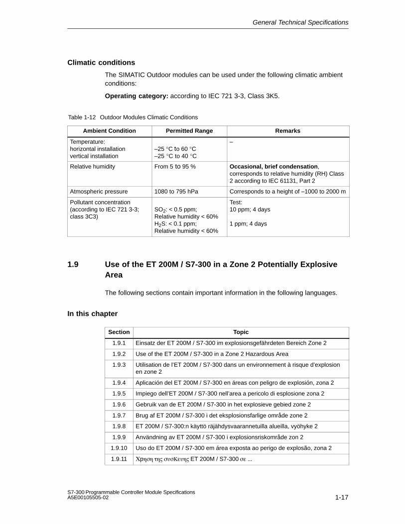
General Technical Specifications
1-17S7-300 Programmable Controller Module SpecificationsA5E00105505-02
Climatic conditions
The SIMATIC Outdoor modules can be used under the following climatic ambientconditions:
Operating category: according to IEC 721 3-3, Class 3K5.
Table 1-12 Outdoor Modules Climatic Conditions
Ambient Condition Permitted Range Remarks
Temperature:horizontal installationvertical installation
–25 °C to 60 °C–25 °C to 40 °C
–
Relative humidity From 5 to 95 % Occasional, brief condensation,corresponds to relative humidity (RH) Class2 according to IEC 61131, Part 2
Atmospheric pressure 1080 to 795 hPa Corresponds to a height of –1000 to 2000 m
Pollutant concentration(according to IEC 721 3-3; class 3C3)
SO2: < 0.5 ppm;Relative humidity < 60%H2S: < 0.1 ppm;Relative humidity < 60%
Test:10 ppm; 4 days
1 ppm; 4 days
1.9 Use of the ET 200M / S7-300 in a Zone 2 Potentially ExplosiveArea
The following sections contain important information in the following languages.
In this chapter
Section Topic
1.9.1 Einsatz der ET 200M / S7-300 im explosionsgefährdeten Bereich Zone 2
1.9.2 Use of the ET 200M / S7-300 in a Zone 2 Hazardous Area
1.9.3 Utilisation de l’ET 200M / S7-300 dans un environnement à risque d’explosionen zone 2
1.9.4 Aplicación del ET 200M / S7-300 en áreas con peligro de explosión, zona 2
1.9.5 Impiego dell’ET 200M / S7-300 nell’area a pericolo di esplosione zona 2
1.9.6 Gebruik van de ET 200M / S7-300 in het explosieve gebied zone 2
1.9.7 Brug af ET 200M / S7-300 i det eksplosionsfarlige område zone 2
1.9.8 ET 200M / S7-300:n käyttö räjähdysvaarannetuilla alueilla, vyöhyke 2
1.9.9 Användning av ET 200M / S7-300 i explosionsriskområde zon 2
1.9.10 Uso do ET 200M / S7-300 em área exposta ao perigo de explosão, zona 2
1.9.11 p ET 200M / S7-300

General Technical Specifications
S7-300 Programmable Controller Module SpecificationsA5E00105505-02
1.9.1 Einsatz der ET 200M / S7-300 im explosions-gefährdeten Bereich Zone 2
Zone 2
Explosionsgefährdete Bereiche werden in Zonen eingeteilt. Die Zonen werdennach der Wahrscheinlichkeit des Vorhandenseins einer explosionsfähigenAtmosphäre unterschieden.
Zone Explosionsgefahr Beispiel2 explosive Gasatmosphäre tritt
nur selten und kurzzeitig aufBereiche um Flanschverbindungen mitFlachdichtungen bei Rohrleitungen ingeschlossenen Räumen
sichererBereich
nein • außerhalb der Zone 2• Standardanwendungen von dezentraler
Peripherie
Nachfolgend finden Sie wichtige Hinweise für die Installation des DezentralenPeripheriegerätes ET 200M und der SIMATIC S7-300 im explosionsgefährdetenBereich.
Weitere Informationen
Weitere Informationen zum ET 200M und zu den verschiedenen S7-300-Baugruppen finden Sie im Handbuch.
Fertigungsort
Siemens AG, Bereich A&DWerner-von-Siemens-Straße 5092224 AmbergGermany
Zulassung
II 3 G EEx nA II T3 .. T6 nach EN 50021 : 1999
Prüfnummer: KEMA 02ATEX1096 X
Hinweis
Baugruppen mit der Zulassung II 3 G EEx nA II T3 .. T6 dürfen nur inAutomatisierungssysteme SIMATIC S7-300 / ET 200M der Gerätekategorie 3eingesetzt werden.

General Technical Specifications
S7-300 Programmable Controller Module SpecificationsA5E00105505-02
Instandhaltung
Für eine Reparatur muss die betroffene Baugruppe an den Fertigungsort geschicktwerden. Nur dort darf die Reparatur durchgeführt werden.
Besondere Bedingungen
1. Das Dezentrale Peripheriegerät ET 200M und die SIMATIC S7-300 müssen ineinen Schaltschrank oder ein metallisches Gehäuse eingebaut werden. Diesemüssen mindestens die Schutzart IP 54 (nach EN 60529) gewährleisten. Dabeisind die Umgebungsbedingungen zu berücksichtigen, in denen das Gerätinstalliert wird. Für das Gehäuse muss eine Herstellererklärung für Zone 2vorliegen (gemäß EN 50021).
2. Wenn am Kabel bzw. an der Kabeleinführung dieses Gehäuses unter Betriebs-bedingungen eine Temperatur > 70 °C erreicht wird oder wenn unter Betriebs-bedingungen die Temperatur an der Aderverzweigung > 80 °C sein kann,müssen die Temperatureigenschaften der Kabel mit den tatsächlichgemessenen Temperaturen übereinstimmen.
3. Die eingesetzten Kabeleinführungen müssen der geforderten IP-Schutzart unddem Abschnitt 7.2 (gemäß EN 50021) entsprechen.
4. Alle Geräte, einschließlich Schalter etc., die an den Ein- und Ausgängen vonET 200M- und S7-300-Systemen angeschlossen werden, müssen für denExplosionsschutz Typ EEx nA oder EEx nC genehmigt sein.
5. Es müssen Maßnahmen getroffen werden, dass die Nennspannung durchTransienten um nicht mehr als 40 % überschritten werden kann.
6. Umgebungstemperaturbereich: 0° C bis 60° C
7. Innerhalb des Gehäuses ist an einem nach dem Öffnen gut sichtbaren Platz einSchild mit folgender Warnung anzubringen:WarnungDas Gehäuse darf nur kurze Zeit geöffnet werden, z. B. für visuelle Diagnose.Betätigen Sie dabei keine Schalter, ziehen oder stecken keine Baugruppen undtrennen keine elektrischen Leitungen (Steckverbindungen).Diese Warnung kann unberücksichtigt bleiben, wenn bekannt ist, dass keineexplosionsgefährdete Atmosphäre herrscht.
Liste der zugelassenen Baugruppen
Die Liste mit den zugelassenen Baugruppen finden Sie im Internet:
http://www4.ad.siemens.de/view/cs/
unter der Beitrags-ID 13702947

General Technical Specifications
S7-300 Programmable Controller Module SpecificationsA5E00105505-02
1.9.2 Use of the ET 200M / S7-300 in a Zone 2Hazardous Area
Zone 2
Hazardous areas are divided up into zones. The zones are distinguished accordingto the probability of the existence of an explosive atmosphere.
Zone Explosion Hazard Example2 Explosive gas atmosphere
occurs only seldom and for ashort time
Areas around flange joints with flatgaskets in pipes in enclosed spaces
Safe area No • Outside zone 2• Standard distributed I/O applications
Below you will find important information on the installation of the ET 200Mdistributed I/O device and the SIMATIC S7-300 in a hazardous area.
Further Information
You will find further information on the ET 200M and the various S7-300 modules inthe manual.
Production Location
Siemens AG, Bereich A&DWerner-von-Siemens-Straße 5092224 AmbergGermany
Certification
II 3 G EEx nA II T3 .. T6 to EN 50021 : 1999
Test number: KEMA 02ATEX1096 X
Note
Modules with II 3 G EEx nA II T3 .. T6 certification can only be used inSIMATIC S7-300/ET 200M automation systems belonging to equipmentcategory 3.

General Technical Specifications
S7-300 Programmable Controller Module SpecificationsA5E00105505-02
Maintenance
If repair is necessary, the affected module must be sent to the production location.Repairs can only be carried there.
Special Conditions
1. The ET 200M distributed I/O device and the SIMATIC S7-300 must be installedin a cabinet or metal housing. These must comply with the IP 54 degree ofprotection as a minimum. The environmental conditions under which theequipment is installed must be taken into account. There must be amanufacturer's declaration for zone 2 available for the housing (in accordancewith EN 50021).
2. If a temperature of > 70 °C is reached in the cable or at the cable entry of thishousing under operating conditions, or if a temperature of > 80 °C can bereached at the junction of the conductors under operating conditions, thetemperature-related properties of the cables must correspond to thetemperatures actually measured.
3. The cable entries used must comply with the required IP degree of protectionand Section 7.2 (in accordance with EN 50021).
4. All devices (including switches, etc.) that are connected to the inputs andoutputs of fail-safe signal modules must be approved for EEx nA or EEx nCexplosion protection.
5. Steps must be taken to ensure that the rated voltage through transients cannotbe exceeded by more than 40 %.
6. Ambient temperature range: 0° C to 60° C
7. A sign containing the following warning must be put up inside the housing in aneasily visible position when the housing is opened:WarningThe housing can only be opened for a short time (e.g. for visual diagnostics). Ifyou do this, do not operate any switches, remove or install any modules ordisconnect any electrical cables (plug-in connections).You can disregard this warning if you know that the atmosphere is nothazardous (i.e. there is no risk of explosion).
List of Approved Modules
You will find the list of approved modules under the ID 13702947 on the Internet:
http://www4.ad.siemens.de/view/cs/.

General Technical Specifications
S7-300 Programmable Controller Module SpecificationsA5E00105505-02
1.9.3 Utilisation de l'ET 200M / S7-300 dans unenvironnement à risque d'explosion en zone 2
Zone 2
Les environnements à risque d'explosion sont répartis en zones. Les zones sedistinguent par la probabilité de présence d'une atmosphère explosive.
Zone Risque d'explosion Exemple2 Formation rare et brève d'une
atmosphère gazeuse explosiveEnvironnement de raccords à joints platsdans le cas de conduites dans des locauxfermés
Zone sûre Non • A l'extérieur de la zone 2• Utilisation standard de périphérie
décentralisée
Vous trouverez ci-après des remarques importantes pour l'installation de la stationde périphérie décentralisée ET 200M et du SIMATIC S7-300 dans unenvironnement présentant un risque d'explosion.
Informations complémentaires
Des informations complémentaires sur l'ET 200M et les divers modules S7-300 setrouvent dans le manuel.
Lieu de production
Siemens AG, Bereich A&DWerner-von-Siemens-Straße 5092224 AmbergGermany
Homologation
II 3 G EEx nA II T3 .. T6 selon EN 50021 : 1999
Numéro de contrôle : KEMA 02ATEX1096 X
Nota
Les modules homologués II 3 G EEx nA II T3 .. T6 ne peuvent être utilisésque dans des automates SIMATIC S7-300 / ET 200M de catégorie 3.

General Technical Specifications
S7-300 Programmable Controller Module SpecificationsA5E00105505-02
Entretien
Si une réparation est nécessaire, le module concerné doit être expédié au lieu deproduction. La réparation ne doit être effectuée qu'en ce lieu.
Conditions particulières
1. La station de périphérie décentralisée ET 200M et le SIMATIC S7-300 doiventêtre installés dans une armoire ou un boîtier métallique. Ceux-ci doivent assurerau moins l'indice de protection IP 54. Il faut alors tenir compte des conditionsd'environnement dans lesquelles l'appareil est installé. Le boîtier doit fairel’objet d’une déclaration de conformité du fabricant pour la zone 2 (selonEN 50021).
2. Si dans les conditions d’exploitation, une température > 70 °C est atteinte auniveau du câble ou de l’entrée du câble dans ce boîtier, ou bien si latempérature au niveau de la dérivation des conducteurs peut être > 80 °C, lescapacités de résistance thermique des câbles doivent corespondre auxtempératures effectivement mesurées.
3. Les entrées de câbles utilisées doivent avoir le niveau de protection IP exigé etêtre conformes au paragraphe 7.2 (selon EN 50021).
4. Tous les appareillages (y compris les interrupteurs, etc.) raccordés aux entréeset sorties de modules de signaux à sécurité intrinsèque doivent êtrehomologués pour la protection antidéflagrante type EEx nA ou EEx nC.
5. Il faut prendre des mesures pour que la tension nominale ne puisse pas êtredépassée de plus de 40% sous l’influence de transitoires.
6. Plage de température ambiante : 0° C à 60° C
7. A l’intérieur du boîtier, il faut placer, à un endroit bien visible après ouverture,une plaquette comportant l’avertissement suivant :AvertissementOuvir le boîtier le moins longtemps possible, par exemple pour effectuer undiagnostic visuel. Ce faisant, n’actionnez aucun commutateur, ne déconnectezaucun module et ne débanchez pas de câbles électriques (connexions).Le respect de cet avertissement n’est pas impératif s’il est certain quel’environnement ne présente pas de risque d’explosion.
Liste des modules homologués
Vous trouverez sur Internet la liste des modules homologués :
http://www4.ad.siemens.de/view/cs/
référence ID 13702947

General Technical Specifications
S7-300 Programmable Controller Module SpecificationsA5E00105505-02
1.9.4 Aplicación de la ET 200M / S7-300 en áreas conpeligro de explosión, zona 2
Zona 2
Las áreas con peligro de explosión se clasifican en zonas. Las zonas sediferencian según la probabilidad de la existencia de una atmósfera capaz de sufriruna explosión.
Zona Peligro de explosión Ejemplo2 La atmósfera explosiva de gas
sólo se presenta rara vez y muybrevemente
Áreas alrededor de uniones abridadas conjuntas planas en tuberías en localescerrados
Área segura No • fuera de la zona 2• Aplicaciones estándar de la periferia
descentralizada
A continuación encontrará importantes informaciones para la instalación de launidad periférica descentralizada ET 200M y del SIMATIC S7-300 en áreas conpeligro de explosión.
Otras informaciones
Encontrará otras informaciones relativas a la ET 200S y a los distintos módulosS7-300 en el Manual.
Lugar de fabricación
Siemens AG, Bereich A&DWerner-von-Siemens-Straße 5092224 AmbergGermany
Homologación
II 3 G EEx nA II T3 .. T6 según norma EN 50021 : 1999
Número de comprobación: KEMA 02ATEX1096 X
Nota
Los módulos con la homologación II 3 G EEx nA II T3 .. T6 pueden utilizarseúnicamente en los autómatas programables SIMATIC S7-300 / ET 200M de lacategoría de equipo 3.

General Technical Specifications
S7-300 Programmable Controller Module SpecificationsA5E00105505-02
Mantenimiento
Para una reparación se ha de remitir el módulo afectado al lugar de fabricación.Sólo allí se puede realizar la reparación.
Condiciones especiales
1. La unidad periférica descentralizada ET 200M y el SIMATIC S7-300 se han demontar en un armario eléctrico de distribución o en una carcasa metálica. Éstosdeben garantizar como mínimo el grado de protección IP 54. Para ello se hande tener en cuenta las condiciones ambientales, en las cuales se instala elequipo. La caja deberá contar con una declaración del fabricante para la zona 2(conforme a EN 50021).
2. Si durante la operación se alcanzara una temperatura > 70° C en el cable o laentrada de cables de esta caja o bien una temperatura > 80° C en labifurcación de hilos, deberán adaptarse las propiedades térmicas de los cablesa las temperaturas medidas efectivamente.
3. Las entradas de cable utilizadas deben cumplir el grado de protección IPexigido y lo expuesto en el apartado 7.2 (conforme a EN 50021).
4. Todos los dispositivos –inclusive interruptores, etc.– conectados a las entradasy salidas de módulos de señales de alta disponibilidad deben estarhomologados para la protección contra explosiones del tipo EEx nA o EEx nC.
5. Es necesario adoptar las medidas necesarias para evitar que la tensiónnominal pueda rebasar en más del 40 % debido a efectos transitorios.
6. Margen de temperatura ambiente: 0° C hasta 60° C
7. Dentro de la caja deberá colocarse en un lugar perfectamente visible tras suapertura un rótulo con la siguiente advertencia:PrecauciónAbrir la caja sólo brevemente, p.ej. para el diagnóstico visual. Durante estetiempo Ud. no deberá activar ningún interruptor, desenchufar o enchufarmódulos ni separar conductores eléctricos (conexiones enchufables).Esta advertencia puede ignorarse si Ud. sabe que en la atmósfera existente nohay peligro de explosión.
Lista de los módulos homologados
En la internet hallará Ud. una lista con los módulos homologados:
http://www4.ad.siemens.de/view/cs/
bajo el ID de asignación 13702947

General Technical Specifications
S7-300 Programmable Controller Module SpecificationsA5E00105505-02
1.9.5 Impiego dell'ET 200M / S7-300 nell'area apericolo di esplosione zona 2
Zona 2
Le aree a pericolo di esplosione vengono suddivise in zone. Le zone vengonodistinte secondo la probabilità della presenza di un'atmosfera esplosiva.
Zona Pericolo di esplosione Esempio2 L'atmosfera esplosiva si
presente solo raramente ebrevemente
Aree intorno a collegamenti a flange conguarnizioni piatte nelle condotte inambienti chiusi
Area sicura No • Al di fuori della zona 2• Applicazioni standard di periferia
decentrata
Qui di seguito sono riportate delle avvertenze importanti per l'installazione dell'unitàdi periferia decentrata ET 200M e del SIMATIC S7-300 nell'area a pericolo diesplosione.
Ulteriori informazioni
Ulteriori informazioni sull'ET 200M e sulle diverse unità S7-300 si trovano nelmanuale.
Luogo di produzione
Siemens AG, Bereich A&DWerner-von-Siemens-Straße 5092224 AmbergGermany
Autorizzazione
II 3 G EEx nA II T3 .. T6 secondo EN 50021 : 1999
Numero di controllo: KEMA 02ATEX1096 X
Avvertenza
Le unità con l'autorizzazione II 3 G EEx nA II T3 .. T6 possono essereimpiegate solo nei sistemi di controllori programmabili SIMATIC S7-300 / ET 200Mdella categoria di apparecchiature 3.

General Technical Specifications
S7-300 Programmable Controller Module SpecificationsA5E00105505-02
Manutenzione
Per una riparazione, l'unità interessata deve essere inviata al luogo di produzione.La riparazione può essere effettuata solo lì.
Condizioni particolari
1. L'unità di periferia decentrata ET 200M e il SIMATIC S7-300 devono esseremontati in un armadio elettrico o in un contenitore metallico. Questi devonoassicurare almeno il tipo di protezione IP 54. In questo caso bisogna tenereconto delle condizioni ambientali nelle quali l'apparecchiatura viene installata.Per il contenitore deve essere presente una dichiarazione del costruttore per lazona 2 (secondo EN 50021).
2. Se nei cavi o nel loro punto di ingresso in questo contenitore viene raggiunta incondizioni di esercizio una temperatura > 70 °C o se in condizioni di esercizio latemperatura nella derivazione dei fili può essere > 80 °C, le caratteristiche ditemperatura dei cavi devono essere conformi alla temperatura effettivamentemisurata.
3. Gli ingressi dei cavi usati devono essere conformi al tipo di protezione richiestoe alla sezione 7.2 (secondo EN 50021).
4. Tutte le apparecchiature, inclusi interruttori, ecc. che vengono collegati agliingressi/uscite di unità di segnale ad elevata sicurezza, devono essere statiomologati per la protezione da esplosione tipo EEx nA o EEx nC.
5. Devono essere prese delle misure per evitare che la tensione nominale possaessere superata per più del 40% da parte di transienti.
6. Campo termico ambientale: da 0° C a 60° C
7. All’interno del contenitore va apportata, in un luogo ben visibile dopo l’apertura,una targhetta con il seguente avvertimento:AttenzioneIl contenitore può rimanere aperto solo per breve tempo, ad esempio per unadiagnostica a vista. In tal caso non azionare alcun interruttore, non disinnestareo innestare unità e non staccare connessioni elettriche (connettori).Non è necessario tenere conto di questo avvertimento se è noto che non c’èun’atmosfera a rischio di esplosione.
Elenco delle unità abilitate
La lista con le unità omologate si trova in Internet al sito:
http://www4.ad.siemens.de/view/cs/
all’ID di voce 13702947

General Technical Specifications
S7-300 Programmable Controller Module SpecificationsA5E00105505-02
1.9.6 Gebruik van de ET 200M / S7-300 in hetexplosief gebied zone 2
Zone 2
Explosieve gebieden worden ingedeeld in zones. Bij de zones wordtonderscheiden volgens de waarschijnlijkheid van de aanwezigheid van eenexplosieve atmosfeer.
Zone Explosiegevaar Voorbeeld2 Een explosieve gasatmosfeer
treedt maar zelden op en voorkorte duur
Gebieden rond flensverbindingen metpakkingen bij buisleidingen in geslotenvertrekken
Veiliggebied
Neen • Buiten de zone 2• Standaardtoepassingen van decentrale
periferie
Hierna vindt u belangrijke aanwijzingen voor de installatie van het decentraleperiferieapparaat ET 200M en van de SIMATIC S7-300 in het explosief gebied.
Verdere informatie
In het handboek vindt u verdere informatie over de ET 200M en over deverschillendeS7-300-modulen.
Productieplaats
Siemens AG, Bereich A&DWerner-von-Siemens-Strasse 5092224 AmbergGermany
Vergunning
II 3 G EEx nA II T3 .. T6 conform EN 50021 : 1999
Keuringsnummer: KEMA 02ATEX1096 X
Opmerking
Modulen met de vergunning II 3 G EEx nA II T3 .. T6 mogen slechts wordengebruikt in automatiseringssystemen SIMATIC S7-300 / ET 200M van deapparaatcategorie 3.

General Technical Specifications
S7-300 Programmable Controller Module SpecificationsA5E00105505-02
Instandhouding
Voor een reparatie moet de betreffende module naar de plaats van vervaardigingworden gestuurd. Alleen daar mag de reparatie worden uitgevoerd.
Speciale voorwaarden
1. Het decentrale periferieapparaat ET 200M en de SIMATIC S7-300 moetenworden ingebouwd in een schakelkast of in een behuizing van metaal. Dezemoeten minstens de veiligheidsgraad IP 54 waarborgen. Hierbij dient rekeningte worden gehouden met de omgevingsvoorwaarden waarin het apparaat wordtgeïnstalleerd. Voor de behuizing dient een verklaring van de fabrikant voorzone 2 te worden ingediend (volgens EN 50021).
2. Als aan de kabel of aan de kabelinvoering van deze behuizing onderbedrijfsomstandigheden een temperatuur wordt bereikt > 70 °C of als onderbedrijfsomstandigheden de temperatuur aan de adervertakking > 80 °C kanzijn, moeten de temperatuureigenschappen van de kabel overeenstemmen metde werkelijk gemeten temperaturen.
3. De aangebrachte kabelinvoeringen moeten de vereiste IP-veiligheidsgraadhebben en in overeenstemming zijn met alinea 7.2 (volgens EN 50021).
4. Alle apparaten, schakelaars enz. inbegrepen, die worden aangesloten op de in-en uitgangen van tegen fouten beveiligde signaalmodulen, moeten zijngoedgekeurd voor de explosiebeveiliging type EEx nA of EEx nC.
5. Er dienen maatregelen te worden getroffen, zodat de nominale spanning doortransiënten met niet meer dan 40 % kan worden overschreden.
6. Omgevingstemperatuurbereik: 0° C tot 60° C
7. Binnen de behuizing dient op een na het openen goed zichtbare plaats eenbord te worden aangebracht met de volgende waarschuwing:WaarschuwingDe behuizing mag slechts voor korte tijd worden geopend, bijv. voor een visuelediagnose. Bedien hierbij geen schakelaar, trek of steek geen modulen enontkoppel geen elektrische leidingen (steekverbindingen).Deze waarschuwing kan buiten beschouwing blijven, indien bekend is dat ergeen explosieve atmosfeer heerst.
Lijst van de toegelaten modulen
De lijst met de toegelaten modulen vindt u in het internet:
http://www4.ad.siemens.de/view/cs/
onder de bijdrage-ID 13702947

General Technical Specifications
S7-300 Programmable Controller Module SpecificationsA5E00105505-02
1.9.7 Brug af ET 200M / S7-300 i det eksplosionfarligeområde zone 2
Zone 2
Eksplosionsfarlige områder inddeles i zoner. Zonerne adskiller sig indbyrdes efterhvor sandsynligt det er, at der er en eksplosiv atmosfære.
Zone Eksplosionsfare Eksempel2 Eksplosiv gasatmosfære
optræder kun sjældent og varerkort
Områder rundt om flangeforbindelser medflade pakninger ved rørledninger i lukkederum
Sikkertområde
Nej • Uden for zone 2• Standardanvendelser decentral periferi
I det følgende findes vigtige henvisninger vedr. installation af det decentraleperiferiudstyr ET 200M og SIMATIC S7-300 i det eksplosionfarlige område.
Yderligere informationer
Yderligere informationer om ET 200M og de forskellige S7-300-komponenter findesi manualen.
Produktionssted
Siemens AG, Bereich A&DWerner-von-Siemens-Straße 5092224 AmbergGermany
Godkendelse
II 3 G EEx nA II T3 .. T6 efter EN 50021 : 1999
Kontrolnummer: KEMA 02ATEX1096 X
Bemærk
Komponenter med godkendelsen II 3 G EEx nA II T3 .. T6 må kun monteres iautomatiseringssystemer SIMATIC S7-300 / ET 200M - udstyrskategori 3.

General Technical Specifications
S7-300 Programmable Controller Module SpecificationsA5E00105505-02
Vedligeholdelse
Skal den pågældende komponent repareres, bedes De sende den tilproduktionsstedet. Reparation må kun udføres der.
Særlige betingelser
1. Det decentrale periferiudstyr ET 200M og SIMATIC S7-300 skal monteres i etkontrolskab eller et metalkabinet. Disse skal mindst kunne sikrebeskyttelsesklasse IP 54. I denne forbindelse skal der tages højde for deomgivelsestemperaturer, i hvilke udstyret er installeret. Der skal væreudarbejdet en erklæring fra fabrikanten for kabinettet for zone 2 (iht. EN 50021).
2. Hvis kablet eller kabelindføringen på dette hus når op på en temperatur på> 70 °C under driftsbetingelser eller hvis temperaturen på åreforegreningen kanvære > 80 °C under driftsbetingelser, skal kablernes temperaturegenskaberstemme overens med de temperaturer, der rent faktisk måles.
3. De benyttede kabelindføringer skal være i overensstemmelse med denkrævede IP-beskyttelsestype og afsnittet 7.2 (iht. EN 50021).
4. Alle apparater, inkl. kontakter osv., der forbindes med ind- og udgangene tilfejlsikre signalkomponenter, skal være godkendt til eksplosionsbeskyttelse aftype EEx nA eller EEx nC.
5. Der skal træffes foranstaltninger, der sørger for, at den nominelle spænding viatransienter ikke kan overskrides mere end 40 %.
6. Omgivelsestemperaturområde: 0° C til 60° C
7. I kabinettet skal der anbringes et skilt, der skal kunne ses, når kabinettet åbnes.Dette skilt skal have følgende advarsel:AdvarselKabinettet må kun åbnes i kort tid, f.eks. til visuel diagnose. Tryk i denneforbindelse ikke på kontakter, træk eller isæt ikke komponenter og afbryd ikkeelektriske ledninger (stikforbindelser).Denne advarsel skal der ikke tages højde for, hvis man ved, at der ikke ernogen eksplosionsfarlig atmosfære.
Liste over godkendte komponenter
Listen med de godkendte komponenter findes på internettet:
http://www4.ad.siemens.de/view/cs/
under bidrags-ID 13702947

General Technical Specifications
S7-300 Programmable Controller Module SpecificationsA5E00105505-02
1.9.8 ET 200M / S7-300:n käyttöräjähdysvaarannetuilla alueilla, vyöhyke 2
Vyöhyke 2
Räjähdysvaarannetut alueet jaetaan vyöhykkeisiin. Vyöhykkeet erotellaanräjähdyskelpoisen ilmakehän olemassa olon todennäköisyyden mukaan.
Vyöhyke Räjähdysvaara Esimerkki2 Räjähtävä kaasuilmakehä
ilmaantuu vain harvoin jalyhytaikaisesti
Alueet putkistojen lattatiivisteillä varustuillalaippaliitoksilla suljetuissa tiloissa
turvallinenalue
Ei • vyöhykkeen 2 ulkopuolella• Hajautetun ulkopiirin vakiosovellukset
Seuraavasta löydätte tärkeitä ohjeita hajautetun ulkopiirilaitteen ET 200M jaSIMATIC S7-300 asennukseen räjähdysvaarannetuilla alueilla.
Lisätietoja
Lisätietoja ET 200M:ään ja erilaisiin S7-300-rakenneryhmiin löydätte ohjekirjasta.
Valmistuspaikka
Siemens AG, Bereich A&DWerner-von-Siemens-Straße 5092224 AmbergGermany
Hyväksyntä
II 3 G EEx nA II T3 .. T6 EN 50021 mukaan: 1999
Tarkastusnumero: KEMA 02ATEX1096 X
Ohje
Rakenneryhmät hyväksynnän II 3 G EEx nA II T3 .. T6 kanssa saadaankäyttää ainoastaan laitekategorian 3 automatisointijärjestelmissä SIMATIC S7-300 /ET 200M.

General Technical Specifications
S7-300 Programmable Controller Module SpecificationsA5E00105505-02
Kunnossapito
Korjausta varten täytyy kyseinen rakenneryhmä lähettää valmistuspaikkaan.Korjaus voidaan suorittaa ainoastaan siellä.
Erityiset vaatimukset
1. Hajautettu ulkopiirilaite ET 200M ja SIMATIC S7-300 täytyy asentaakytkentäkaappiin tai metalliseen koteloon. Näiden täytyy olla vähintäänkotelointiluokan IP 54 mukaisia. Tällöin on huomioitava ympäristöolosuhteet,johon laite asennetaan. Kotelolle täytyy olla valmistajaselvitys vyöhykettä 2varten (EN 50021 mukaan).
2. Kun johdolla tai tämän kotelon johdon sisäänviennillä saavutetaan > 70 °Clämpötila tai kun käyttöolosuhteissa lämpötila voi piuhajaotuksella olla > 80 °C,täytyy johdon lämpötilaominaisuuksien vastata todellisesti mitattuja lämpötiloja.
3. Käytettyjen johtojen sisäänohjauksien täytyy olla vaaditun IP-kotelointiluokan jakohdan 7.2 (EN 50021 mukaan) mukaisia.
4. Kaikkien laitteiden, kytkimet jne. mukaan lukien, jotka liitetään virheiltäsuojattujen signaalirakenneryhmien tuloille ja lähdöille, täytyy olla hyväksyttyjätyypin EEx nA tai EEx nC räjähdyssuojausta varten.
5. Toimenpiteet täytyy suorittaa, ettei nimellisjännite voi transienttien kautta ylittyäenemmän kuin 40 %.
6. Ympäristölämpötila-alue: 0° C ... 60° C
7. Kotelon sisälle, avauksen jälkeen näkyvälle paikalle, on kiinnitettävä kilpi, jossaon seuraava varoitus:VaroitusKotelo saadaan avata ainoastaan lyhyeksi ajaksi, esim. visuaalista diagnoosiavarten. Älä tällöin käytä mitään kytkimiä, vedä tai liitä mitään rakenneryhmiä,äläkä erota mitään sähköjohtoja (pistoliittimiä).Tätä varoitusta ei tarvitse huomioida, kun on tiedossa, että minkäänlaistaräjähdysvaarannettua ilmakehää ei ole olemassa.
Hyväksyttyjen rakenneryhmien lista
Lista hyväksiytyistä rakennesarjoista löytyy internetistä osoitteesta:
http://www4.ad.siemens.de/view/cs/
käyttäjätunnuksella 13702947

General Technical Specifications
S7-300 Programmable Controller Module SpecificationsA5E00105505-02
1.9.9 Användning av ET 200M / S7-300 iexplosionsriskområde zon 2
Zon 2
Explosionsriskområden delas in i zoner. Zonerna delas in enligt sannolikheten atten atmosfär med explosionsfara föreligger.
Zon Explosionsfara Exempel2 Explosiv gasatmosfär uppstår
endast sällan eller kortvarigtOmråden kring flänsförbindelser medpackningar vid rörledningar i slutnautrymmen
Säkertområde
Nej • Utanför zon 2• Standardanvändning av decentral
periferi
Nedan följer viktiga anvisningar om installationen av den decentralaperiferienheten ET 200M och SIMATIC°S7-300 i ett explosionsriskområde.
Ytterligare information
Ytterligare information om ET 200M och de olika S7-300-komponentgruppernafinner du i handboken.
Tillverkningsort
Siemens AG, Bereich A&DWerner-von-Siemens-Straße 5092224 AmbergGermany
Godkännande
II 3 G EEx nA II T3 .. T6 enligt EN 50021 : 1999
Kontrollnummer: KEMA 02ATEX1096 X
Anvisning
Komponentgrupper med godkännande II 3 G EEx nA II T3 .. T6 får endastanvändas i automatiseringssystemen SIMATIC S7-300 / ET°200M frånapparatgrupp 3.

General Technical Specifications
S7-300 Programmable Controller Module SpecificationsA5E00105505-02
Underhåll
Vid reparation måste den aktuella komponentgruppen insändas till tillverkaren.Reparationer får endast genomföras där.
Särskilda villkor
1. Den decentrala periferienheten ET 200M och SIMATIC°S7-300 måste monterasi ett kopplingsskåp eller metallhus. Dessa måste minst vara av skyddsklassIP 54. Därvid ska omgivningsvillkoren där enheten installeras beaktas. Förkåpan måste en tillverkardeklaration för zon 2 föreligga (enligt EN 50021).
2. Om en temperatur på > 70°C uppnås vid husets kabel resp kabelinföring underdriftvillkor eller om temperaturen vid trådförgreningen kan vara > 80°C underdriftvillkor, måste kabelns temperaturegenskaper överensstämma med denverkligen uppmätta temperaturen.
3. De använda kabelinföringarna måste uppfylla kraven i det krävda IP-skyddsutförandet och i avsnitt 7.2 (enligt EN 50021).
4. Alla apparater, inklusive brytare osv, som ansluts till felsäkrade signalenhetersin- och utgångar, måste vara godkända för explosionsskydd av typ EEx nA ellerEEx nC.
5. Åtgärder måste vidtas så, att märkspänningen ej kan överskridas med mer än40°% genom transienter.
6. Omgivningstemperatur: 0° C till 60° C
7. När huset öppnats ska en skylt med följande varning monteras på ett tydligtsynligt ställe huset:VarningHuset får endast öppnas under kort tid, t ex för visuell diagnos. Använd därvidinga brytare, lossa eller anslut inga enheter och frånskilj inga elektriskaledningar (insticksanslutningar).Ingen hänsyn måste tas till denna varning om det är säkert att det inte rådernågon explosionsfarlig atmosfär.
Lista över godkända komponentgrupper
Lista över godkända enheter återfinns i Internet:
http://www4.ad.siemens.de/view/cs/
under bidrags-ID 13702947

General Technical Specifications
S7-300 Programmable Controller Module SpecificationsA5E00105505-02
1.9.10 Uso do ET 200M / S7-300 em área exposta aoperigo de explosão 2
Zona 2
As áreas expostas ao perigo de explosão são divididas em zonas. As zonas sãodiferenciadas de acordo com a probabilidade da existência de uma atmosferaexplosiva.
Zona Perigo de explosão Exemplo2 Só raramente e por um breve
período de tempo surgematmosferas explosivas
Áreas em torno de ligações flangeadascom vedações chatas em tubulações emrecintos fechados
Área segura Não • fora da zona 2• Aplicações descentralizadas de
periferia descentralizada
A seguir, o encontrará avisos importantes para a instalação do aparelho periféricodescentralizado ET 200M e da SIMATIC S7-300 em área exposta ao perigo deexplosão.
Mais informações
Para obter mais informações sobre o ET 200M e os diversos grupos construtivosS7-300, consulte o manual.
Local de produção
Siemens AG, Bereich A&DWerner-von-Siemens-Straße 5092224 AmbergGermany
Licença
II 3 G EEx nA II T3 .. T6 seg. EN 50021 : 1999
Número de ensaio: KEMA 02ATEX1096 X
Aviso
Componentes com a licença II 3 G EEx nA II T3 .. T6 só podem seraplicados em sistemas de automação SIMATIC S7-300 / ET 200M da categoria deaparelho 3.

General Technical Specifications
S7-300 Programmable Controller Module SpecificationsA5E00105505-02
Reparo
Os grupos construtivos em questão devem ser remetidos para o local de produçãoa fim de que seja realizado o reparo. Apenas lá deve ser efetuado o reparo.
Condições especiais
1. O aparelho periférico ET 200M e a SIMATIC S7-300 devem ser montados emum armário de distribuição ou em uma caixa metálica. Estes devem garantir nomínimo o tipo de proteção IP 54. Durante este trabalho deverão ser levados emconsideração as condições locais, nas quais o aparelho será instalado. Para acaixa deverá ser apresentada uma declaração do fabricante para a zona 2 (deacordo com EN 50021).
2. Caso no cabo ou na entrada do cabo desta carcaça sob as condiçõesoperacionais seja atingida uma temperatura de > 70 °C, ou caso sob condiçõesoperacionais a temperatura na ramificação do fio poderá atingir > 80 °C, ascaraterísticas de temperatura deverão corresponder às temperaturas realmentemedidas.
3. As entradas de cabo utilizadas devem corresponder ao tipo exigido deproteção IP e à seção 7.2 (de acordo com o EN 50021).
4. Todos os aparelhos, inclusive as chaves, etc., que estejam conectadas ementradas e saídas de módulos de sinais protegidos contra erro, devem possuira licença para a proteção de explosão do tipo EEx nA ou EEx nC.
5. Precisam ser tomadas medidas para que a tensão nominal através detransitórios não possa ser ultrapassada em mais que 40 %.
6. Área de temperatura ambiente: 0° C até 60° C
7. No âmbito da carcaça deve ser colocada, após a abertura, em um ponto bemvisível uma placa com a seguinte advertência:AdvertênciaA carcaça deve ser aberta apenas por um breve período de tempo, por ex. paradiagnóstico visual. Não acione nenhum interruptor, não retire ou conectenenhum módulo e não separe nenhum fio elétrico (ligações de tomada).Esta advertência poderá ser ignorada caso se saiba que não há nenhumaatmosfera sujeita ao perigo de explosão.
Lista dos componentes autorizados
A lista com os módulos autorizados encontram-se na Internet:
http://www4.ad.siemens.de/view/cs/
sob o número de ID 13702947

General Technical Specifications
S7-300 Programmable Controller Module SpecificationsA5E00105505-02
1.9.11 Χρήση της συσκευής ET 200M / S7-300 σεεπικίνδυνη για έκρηξη περιοχή, ζώνη 2
Ζώνη 2
Οι επικίνδυνες για έκρηξη περιοχές χωρίζονται σε ζώνες. Οι ζώνες διαφέρουνσύµφωνα µε την πιθανότητα ύπαρξης ενός ικανού για έκρηξη περιβάλλοντος.
Ζώνη Κίνδυνος έκρηξης Παράδειγµα2 Εκρηκτικό περιβάλλον αερίου
παρουσιάζεται µόνο σπάνια καιγια σύντοµο χρονικό διάστηµα
Περιοχές γύρω από φλαντζωτέςσυνδέσεις µε τσιµούχες σε σωληνώσεις σεκλειστούς χώρους
Ασφαλήςπεριοχή
Όχι • Εκτός της ζώνης 2• Τυπικές εφαρµογές αποκεντρωµένηςπεριφέρειας
Στη συνέχεια θα βρείτε σηµαντικές υποδείξεις για την εγκατάσταση τηςαποκεντρωµένης περιφερειακής συσκευής ET 200M και του δοµικούσυγκροτήµατος SIMATIC S7-300 σε επικίνδυνη για έκρηξη περιοχή.
Επιπλέον πληροφορίες
Επιπλέον πληροφορίες για τη συσκευή ET 200M και για τα διάφορα δοµικάσυγκροτήµατα (ενότητες) S7-300 θα βρείτε στο εγχειρίδιο.
Τόπος κατασκευής
Siemens AG, Bereich A&DWerner-von-Siemens-Straße 5092224 AmbergGermany
Άδεια
II 3 G EEx nA II T3 .. T6 σύµφωνα µε το πρότυποEN 50021 : 1999
Αριθµός ελέγχου: KEMA 02ATEX1096 X
Υπόδειξη
Τα δοµικά συγκροτήµατα µε την άδεια II 3 G EEx nA II T3 .. T6 επιτρέπεται νατοποθετηθούν µόνο σε συστήµατα αυτοµατισµού SIMATIC S7-300 / ET 200M τηςκατηγορίας συσκευής 3.

General Technical Specifications
S7-300 Programmable Controller Module SpecificationsA5E00105505-02
Συντήρηση
Για µια επισκευή πρέπει να σταλθεί το αντίστοιχο δοµικό συγκρότηµα στον τόποκατασκευής. Μόνο εκεί επιτρέπεται να γίνει η επισκευή.
Ιδιαίτερες προϋποθέσεις
1. Η αποκεντρωµένη περιφερειακή συσκευή ET 200M και το δοµικό συγκρότηµαSIMATIC S7-300 πρέπει να ενσωµατωθούν σε ένα ερµάριο ζεύξης ή σε έναµεταλλικό περίβληµα. Αυτά πρέπει να εξασφαλίζουν το λιγότερο το βαθµόπροστασίας IP 54. Σε αυτήν την περίπτωση πρέπει να ληφθούν υπόψη οιπεριβαλλοντικές συνθήκες, στις οποίες θα εγκατασταθεί η συσκευή. Για τοπερίβληµα πρέπει να προβλέπεται δήλωση του κατασκευαστή για τη ζώνη 2(σύµφωνα µε το πρότυπο EN 50021).
2. Εάν στο καλώδιο ή στην είσοδο του καλωδίου αυτού του περιβλήµατος κάτωαπό συνθήκες λειτουργίας η θερµοκρασία ξεπεράσει τους 70 °C ή όταν κάτωαπό συνθήκες λειτουργίας η θερµοκρασία στη διακλάδωση του σύρµατοςµπορεί να είναι µεγαλύτερη από 80 °C, πρέπει οι θερµοκρασιακές ιδιότητες τωνκαλωδίων να ταυτίζονται µε τις πραγµατικά µετρηµένες θερµοκρασίες.
3. Οι χρησιµοποιούµενες εισόδοι καλωδίων πρέπει να συµµορφώνονται µε τοβαθµό προστασίας IP 54 στην ενότητα 7.2 (σύµφωνα µε το πρότυποEN 50021).
4. Όλες οι συσκευές, συµπεριλαµβανοµένων διακοπτών κ.α., που συνδέονται στιςεισόδους και εξόδους δοµικών συγκροτηµάτων ασφαλών σηµάτων, πρέπει ναφέρουν εγκριµένη προστασία κατά έκρηξης τύπου EEx nA ή EEx nC.
5. Πρέπει να ληφθούν µέτρα, να µην µπορεί να γίνει υπέρβαση της ονοµαστικήςτάσης µέσω αιφνίδιας µεταβολής της τάσης πάνω από 40 %.
6. Περιοχή θερµοκρασίας περιβάλλοντος: 0° C έως 60° C
7. Πρέπει να τοποθετηθεί µέσα στο περίβληµα σε ευδιάκριτο σηµείο µετά τοάνοιγµα µία πινακίδα µε την ακόλουθη προειδοποίηση:ΠροειδοποίησηΤο περίβληµα επιτρέπεται να ανοίγει µόνο για µικρό χρονικό διάστηµα, π.χ. γιατη διενέργεια οπτικής διάγνωσης. Μην κάνετε χρήση διακοπτών, µην τραβάτε ήεµβυσµατώνετε δοµικά συγκροτήµατα και µη διαχωρίζετε ηλεκτροφόρουςαγωγούς (εµβσυµατώσιµες συνδέσεις).Η προειδοποίηση αυτή δε χρειάζεται να ληφθεί υπ’ όψιν, εάν είναι γνωστό ότιδεν υφίσταται ατµόσφαιρα παρουσιάζουσα κίνδυνο έκρηξης.
Κατάλογος των εγκεκριµένων δοµικών συγκροτηµάτων
Η λίστα µε τα εγκριµένα δοµικά συγκροτήµατα υπάρχει στο διαδίκτυο:
http://www4.ad.siemens.de/view/cs/
µε τον κωδικό συνδροµής 13702947

General Technical Specifications
1-18S7-300 Programmable Controller Module Specifications
A5E00105505-02

2-1S7-300 Programmable Controller Module SpecificationsA5E00105505-02
Power Supply Modules
Introduction
Various power supply modules are available to supply your S7-300 programmablecontroller and the sensors/actuators with 24 VDC.
Power supply modules
This chapter describes the technical specifications of the power supply modules ofthe S7-300 programmable controller.
In addition to the technical specifications, this chapter describes the following:
The characteristics
Connection diagram
Block diagram
Line protection
Reaction to atypical operating conditions
In this chapter
Section Contents Page
2.1 Power Supply Module PS 305; 2 A; (6ES7 305-1BA80-0AA0) 2-2
2.2 Power Supply Module PS 307; 2 A; (6ES7 307-1BA00-0AA0) 2-6
2.3 Power Supply Module PS 307; 5 A; (6ES7 307-1EAx0-0AA0) 2-10
2.4 Power Supply Module PS 307; 10 A; (6ES7 307-1KA00-0AA0) 2-15
2

Power Supply Modules
2-2S7-300 Programmable Controller Module Specifications
A5E00105505-02
2.1 Power Supply Module PS 305; 2 A; (6ES7 305-1BA80-0AA0)
Order number ”SIMATIC Outdoor module”
6ES7 305-1BA80-0AA0
Characteristics
The PS 305 power supply module (2 A) has the following salient features:
Output current 2 A
Output voltage 24 VDC; proof against short-circuit and open circuit
Connection to DC power supply
(rated input voltage 24/48/72/96/110 VDC)
Reliable isolation to EN 60 950
Can be used as load power supply

Power Supply Modules
2-3S7-300 Programmable Controller Module SpecificationsA5E00105505-02
Wiring schematic of the PS 305; 2 A
Strain-relief assembly
Terminals for systemvoltage and protectivegrounding conductor
Terminals for 24VDC outputvoltage
LED for ”24 VDCoutput voltage available”
On/Off switchfor 24 VDC
24 VDC
L+1
M1L+2
L+2
L+2
M2M2M2
I
Figure 2-1 Wiring Schematic of the PS 305 Power Supply Module (2 A)

Power Supply Modules
2-4S7-300 Programmable Controller Module Specifications
A5E00105505-02
Technical specifications of the PS 305; 2 A (6ES7 305-1BA80-0AA0)
Dimensions and Weight
Dimensions W H D (in millimeters)
80 125 120
Weight Approx. 740 g
Input Rating
Input voltage
Rated value
Voltage range
24/48/72/96/110 VDC
16.8 to 138 VDC
Rated input current
At 24 V
At 48 V
At 72 V
At 96 V
At 110 V
2.7 A
1.3 A
0.9 A
0.65 A
0.6 A
Inrush current (at 25 C) 20 A
I2t (at inrush current) 5 A2s
Output Rating
Output voltage
Rated value
Permitted range
24 VDC
24 V 3 %, stable atno load
Ramp-up time max. 3 s
Output current
Rated value 2 A; 1)
Can be connected inparallel
Short-circuit protection Electronic, nonlatching,from 1.65 to 1.95 IN
Residual ripple max. 150 mVss
Other Parameters
Protection class according toIEC 536 (DIN VDE 0106, Part 1)
I, with protectivegrounding conductor
Insulation
Isolation voltage rating (24 V to input)
150 VAC
Tested with 2800 VDC
Reliable isolation SELV circuit
Buffering of supply failures (at 24/48/72/96/110 V)
> 10 ms
Repeat rate min. 1 s
Efficiency 75%
Power input 64 W
Power loss 16 W
Diagnostics
LED for output voltage available Yes, green LED
1) With limited input voltage range > 24 V (24 to 138 VDC) the PS 305 can be loaded with 3 A.

Power Supply Modules
2-5S7-300 Programmable Controller Module SpecificationsA5E00105505-02
Basic circuit diagram of the PS 305; 2 A
L+2
M2
L+1
M1
24 VDC
I/
U
Figure 2-2 Basic Circuit Diagram of the PS 305 Power Supply Module (2 A)
Line protection
We recommend that you install a miniature circuit-breaker (MCB) (for exampleSiemens 5SN1 series) with the following rating to protect the incoming supplycable of the PS 305 power supply module (2 A):
Rated current at 110 VDC: 10 A
Tripping characteristic (type): C.
Reaction to atypical operating conditions
Table 2-1 Reaction of the PS 305 Power Supply Module (2 A) to Atypical OperatingConditions
If ... ... Then ... 24 VDCLED
... the output circuit is overloaded: I > 3.9 A (dynamic)
3 A < I 3.9 A (static)
Voltage dip, autom. volt. recoveryVoltage drop, shortening of servicelife
Flashes
... the output is short-circuited Output voltage 0 V; automatic voltagerecovery after short circuit has beeneliminated
Dark
An overvoltage occurs on the primaryside
Possible destruction -
There is an undervoltage on the pri-mary side
Automatic disconnection; automaticvoltage recovery
Dark

Power Supply Modules
2-6S7-300 Programmable Controller Module Specifications
A5E00105505-02
2.2 Power Supply Module PS 307; 2 A; (6ES7 307-1BA00-0AA0)
Order number
6ES7 307-1BA00-0AA0
Characteristics
The PS 307 power supply module (2 A) has the following salient features:
Output current 2 A
Output voltage 24 VDC; proof against short-circuit and open circuit
Connection to single-phase AC system
(input voltage 120/230 VAC, 50/60 Hz)
Reliable isolation to EN 60 950
Can be used as load power supply

Power Supply Modules
2-7S7-300 Programmable Controller Module SpecificationsA5E00105505-02
Wiring schematic of the PS 307; 2 A
Strain-reliefassembly
230V
Terminals for systemvoltage and protectivegrounding conductor
Terminals for 24 VDCoutput voltage
Voltage selector
On/Off switch for24 VDC
24 VDC
L1
N
L+M
M
LED for ”24 VDC outputvoltage available”
L+
I
Figure 2-3 Wiring Schematic of the PS 307 Power Supply Module (2 A)
Basic circuit diagram of the PS 307; 2 A
L+
M
L1
N
24 VDC
I/
U
Figure 2-4 Basic Circuit Diagram of the PS 307 Power Supply Module (2 A)

Power Supply Modules
2-8S7-300 Programmable Controller Module Specifications
A5E00105505-02
Line protection
We recommend that you install a miniature circuit-breaker (MCB) (for exampleSiemens 5SN1 series) with the following rating to protect the incoming supplycable of the PS 307 power supply module (2 A):
Rated current at 230 VAC: 6 A
Tripping characteristic (type): C.
Reaction to atypical operating conditions
Table 2-2 Reaction of the PS 307 Power Supply Module (2 A) to Atypical OperatingConditions
If ... ... Then ... 24 VDCLED
... the output circuit is overloaded: I > 2.6 A (dynamic)
2 A < I 2.6 A (static)
Voltage dip, autom. volt. recoveryVoltage drop, shortening of servicelife
Flashes
... the output is short-circuited Output voltage 0 V; automatic voltagerecovery after short circuit has beeneliminated
Dark
An overvoltage occurs on the primaryside
Possible destruction -
There is an undervoltage on the pri-mary side
Automatic disconnection; automaticvoltage recovery
Dark

Power Supply Modules
2-9S7-300 Programmable Controller Module SpecificationsA5E00105505-02
Technical specifications of the PS 307; 2 A (6ES7 307-1BA00-0AA0)
Dimensions and Weight
Dimensions W H D (in millimeters)
50 125 120
Weight Approx. 420 g
Input Rating
Input voltage Rated valueSystem frequency Rated value Permitted range
120 / 230 VAC
50 Hz or 60 Hz47 Hz to 63 Hz
Rated input current At 230 V At 120 V
0.5 A0.8 A
Inrush current (at 25°C) 20 A
I2t (at inrush current) 1 A2s
Output Rating
Output voltage Rated value Permitted range
Ramp-up time
24 VDC24 V 5 %, stable atno loadmax. 2.5 s
Output current Rated value
2 A,Cannot be connected inparallel
Short-circuit protection Electronic, nonlatching,1.1 to 1.3 IN
Residual ripple max. 150 mVss
Other Parameters
Protection class according toIEC 536 (DIN VDE 0106, Part 1)
I, with protective groun-ding conductor
Insulation Rated insulation level
(24 V to L1) Tested with
250 VAC
2800 VDC
Reliable isolation SELV circuit
Bridging of power failures (at 93and/or 187 V) Repeat rate
min. 20 ms
min 1 s
Efficiency 83 %
Power input 58 W
Power loss typ. 10 W
Diagnostics
LED for output voltage available Yes, green LED

Power Supply Modules
2-10S7-300 Programmable Controller Module Specifications
A5E00105505-02
2.3 Power Supply Module PS 307; 5 A; (6ES7 307-1EAx0-0AA0)
Order number: ”Standard module
6ES7 307-1EA00-0AA0
Order number ”SIMATIC Outdoor module”
6ES7 307-1EA80-0AA0
Characteristics
The PS 307 power supply module (5 A) has the following salient features:
Output current 5 A
Output voltage 24 VDC; proof against short-circuit and open circuit
Connection to single-phase AC system
(input voltage 120/230 VAC, 50/60 Hz)
Reliable isolation to EN 60 950
Can be used as load power supply

Power Supply Modules
2-11S7-300 Programmable Controller Module SpecificationsA5E00105505-02
Wiring schematic of the PS 307; 5 A
Strain-relief assembly
Terminals for systemvoltage and protectivegrounding conductor
Terminals for24 VDC outputvoltage
LED for ”24 VDCoutput voltageavailable”
Voltage Selector
On/Off switchfor 24 VDC
230V
24 VDC
L1
NL+
L+
L+
M
M
M
I
Figure 2-5 Wiring Schematic of the PS 307 Power Supply Module (5 A)

Power Supply Modules
2-12S7-300 Programmable Controller Module Specifications
A5E00105505-02
Basic circuit diagram of the PS 307; 5 A
L+
M
L1
N
24 VDC
U
I/
Figure 2-6 Basic Circuit Diagram of the PS 307 Power Supply Module (5 A)
Line protection
We recommend that you install a miniature circuit-breaker (MCB) (for exampleSiemens 5SN1 series) with the following rating to protect the incoming supplycable of the PS 307 power supply module (5 A):
Rated current at 230 VAC: 10 A
Tripping characteristic (type): C.
Reaction to atypical operating conditions
Table 2-3 Reaction of the PS 307 Power Supply Module (5 A) to Atypical OperatingConditions
If ... ... Then ... 24 VDCLED
... the output circuit is overloaded: I > 6.5 A (dynamic)
5 A < I 6.5 A (static)
Voltage dip, autom. volt. recoveryVoltage drop, shortening of service life
Flashes
... the output is short-circuited Output voltage 0 V; automatic voltage reco-very after short circuit has been eliminated
Dark
An overvoltage occurs on the pri-mary side
Possible destruction –
There is an undervoltage on theprimary side
Automatic disconnection; automatic voltagerecovery
Dark

Power Supply Modules
2-13S7-300 Programmable Controller Module SpecificationsA5E00105505-02
Technical specifications of the PS 307; 5 A (6ES7 307-1EA00-0AA0)
Dimensions and Weight
Dimensions W H D (in millimeters)
80 125 120
Weight Approx. 740 g
Input Rating
Input voltage
Rated value 120 / 230 VAC
System frequency
Rated value
Permitted range
50 Hz or 60 Hz
47 Hz to 63 Hz
Rated input current
At 120 V
At 230 V
2 A
1 A
Inrush current (at 25 C) 45 A
I2t (at inrush current) 1.2 A2s
Output Rating
Output voltage
Rated value
Permitted range
24 VDC
24 V 5 %, stable at no load
Ramp-up time max. 2.5 s
Output current
Rated value 5 A
Cannot be connected inparallel
Short-circuit protection Electronic, nonlatching,
from 1.1 to 1.3 IN
Residual ripple max. 150 mVss
Other Parameters
Protection class according toIEC 536 (DIN VDE 0106, Part 1)
I, with protectivegrounding conductor
Insulation
Rated insulation level (24 V to L1)
250 VAC
Tested with 2800 VDC
Reliable isolation SELV circuit
Bridging of power failures (at 93and/or 187 V)
Repeat rate
min. 20 ms
min 1 s
Efficiency 87 %
Power input 138 W
Power loss typ. 18 W
Diagnostics
LED for output voltage available Yes, green LED

Power Supply Modules
2-14S7-300 Programmable Controller Module Specifications
A5E00105505-02
Technical specifications of the PS 307; 5 A (6ES7 307-1EA80-0AA0)
Dimensions and Weight
Dimensions W H H (in millimeters)
80 125 120
Weight Approx. 570 g
Input Rating
Input voltage
Rated value 120/230 VDC
System frequency
Rated value
Permitted range
50 Hz or 60 Hz
47 Hz to 63 Hz
Rated input current
At 120 V
At 230 V
2.1 A
1.2 A
Inrush current (at 25 C) 45 A
I2t (at inrush current) 1.8 A2s
Output Rating
Output voltage
Rated value
Permitted range
Ramp-up time
24 VDC
24 V 3 %
max. 3 s
Output current
Rated value 5 A; cannot beconnected in parallel
Short-circuit protection Electronic, nonlatching,
from 1.1 to 1.3 IN
Residual ripple max. 150 mVss
Other Parameters
Protection class according toIEC 536 (DIN VDE 0106, Part 1)
I, with protectivegrounding conductor
Insulation
Rated insulation level (24 V to L1)
Tested with
250 VAC
2800 VDC
Reliable isolation SELV circuit
Bridging of power failures (at 93and/or 187 V)
Repeat rate
min. 20 ms
min. 1 s
Efficiency 84%
Power input 143 W
Power loss 23 W
Diagnostics
LED for output voltage available Yes, green LED

Power Supply Modules
2-15S7-300 Programmable Controller Module SpecificationsA5E00105505-02
2.4 Power Supply Module PS 307; 10 A; (6ES7 307-1KA00-0AA0)
Order number
6ES7 307-1KA00-0AA0
Characteristics
The PS 307 power supply module (10 A) has the following salient features:
Output current 10 A
Output voltage 24 VDC; proof against short-circuit and open circuit
Connection to single-phase AC system
(input voltage 120/230 VAC, 50/60 Hz)
Reliable isolation to EN 60 950
Can be used as load power supply
Wiring schematic of the PS 307; 10 A
Terminals for systemvoltage and protectivegrounding conductor
Terminals for24 VDCoutput voltage
LED for ”24VDC outputvoltageavailable”
Voltage selector
On/Off switch for24 VDC
230V
24 VDC
L+ML+ML+ML+M
Strain-relief assembly
L1N
I
Figure 2-7 Wiring Schematic of the PS 307 Power Supply Module (10 A)

Power Supply Modules
2-16S7-300 Programmable Controller Module Specifications
A5E00105505-02
Basic circuit diagram of the PS 307; 10 A
L+
M
L1
N
24 VDC
U
I/
Figure 2-8 Basic Circuit Diagram of the PS 307 Power Supply Module (10 A)
Line protection
We recommend that you install a miniature circuit-breaker (MCB) (for example,Siemens 5SN1 series) with the following rating to protect the incoming supplycable of the PS 307 power supply module (10 A):
Rated current at 230 VAC: 16 A
Tripping characteristic (type): C.
Reaction to atypical operating conditions
Table 2-4 Reaction of the PS 307 Power Supply Module (10 A) to Atypical OperatingConditions
If ... Reaction of the Module 24 VDCLED
... the output circuit is overloaded: I > 13 A (dynamic)
10 A < I 13 A (static)
Voltage dip, autom. volt. recoveryVoltage drop, shortening of servicelife
Flashes
... the output is short-circuited Output voltage 0 V; automatic voltagerecovery after short circuit has beeneliminated
Dark
An overvoltage occurs on the primaryside
Possible destruction –
There is an undervoltage on the pri-mary side
Automatic disconnection; automaticvoltage recovery
Dark

Power Supply Modules
2-17S7-300 Programmable Controller Module SpecificationsA5E00105505-02
Technical specifications of the PS 307; 10 A (6ES7 307-1KA00-0AA0)
Dimensions and Weight
Dimensions W H D (in millimeters)
200 125 120
Weight 1.2 kg
Input Rating
Input voltage
Rated value 120 / 230 VAC
System frequency
Rated value
Permitted range
50 Hz or 60 Hz
47 Hz to 63 Hz
Rated input current
At 230 V
At 120 V
1.7 A
3.5 A
Inrush current (at 25 °C) 55 A
I2t (at inrush current) 9 A2s
Output Rating
Output voltage
Rated value
Permitted range
Ramp-up time
24 VDC
24 V 5 %, stable atno load
max. 2.5 s
Output current
Rated value 10 A,
Cannot be connected inparallel
Short-circuit protection Electronic, nonlatching,
1.1 to 1.3 IN
Residual ripple max. 150 mVss
Other Parameters
Protection class according toIEC 536 (DIN VDE 0106, Part 1)
I, with protectivegrounding conductor
Insulation
Rated insulation level (24 V to L1)
Tested with
250 VAC
2800 VDC
Reliable isolation SELV circuit
Bridging of power failures (at 93and/or 187 V)
Repeat rate
min. 20 ms
min 1 s
Efficiency 89 %
Power input 270 W
Power loss typ. 30 W
Diagnostics
LED for output voltage available Yes, green LED

Power Supply Modules
2-18S7-300 Programmable Controller Module Specifications
A5E00105505-02

3-1S7-300 Programmable Controller Module SpecificationsA5E00105505-02
Digital Modules
Changes and improvements compared to the previous edition of the Reference Manual
This chapter describes all new digital modules. Furthermore, two new overviewsections will make it easier for you to access the information:
The ”Module Overview” section shows you the modules that are available,together with their most important characteristics, and helps you quickly to findthe module suitable for your task.
The section entitled ”Sequence of Steps from Choosing to Commissioning theModule” provides the answer to the question ”What must I do in succession tocommission the module quickly and successfully?
Structure of the chapter
The present chapter is broken down into the following subjects:
1. Overview containing the modules that are available here and a description
2. Information that is generally valid – in other words, relating to all digital modules(for example, parameter assignment and diagnostics)
3. Information that refers to specific modules (for example, characteristics,diagram of connections and block diagram, technical specifications and specialcharacteristics of the module):
a) for digital input modules
b) for digital output modules
c) for relay output modules
d) for digital input/output modules
Additional information
Appendix A describes the structure of the parameter sets (data records 0, 1 and128) in the system data. You must be familiar with this configuration if you want tomodify the parameters of the modules in the STEP 7 user program.
Appendix B describes the structure of the diagnostic data (data records 0 and 1) inthe system data. You must be familiar with this configuration if you want toevaluate the diagnostic data of the modules in the STEP 7 user program.
3

Digital Modules
3-2S7-300 Programmable Controller Module Specifications
A5E00105505-02
In this chapter
Section Contents Page
3.1 Module Overview 3-4
3.2 Sequence of Steps from Choosing to Commissioning the DigitalModule
3-10
3.3 Assigning Parameters to Digital Modules 3-11
3.4 Diagnostics of Digital Modules 3-12
3.5 Digital Input Module SM 321; DI 32 24 VDC;(6ES7 321-1BLx0-0AA0)
3-13
3.6 Digital Input Module SM 321; DI 32 120 VAC; (6ES7 321-1EL00-0AA0)
3-16
3.7 Digital Input Module SM 321; DI 16 24 VDC; (6ES7 321-1BHx2-0AA0)
3-18
3.8 Digital Input Module SM 321; DI 16 24 VDC High Speed;(6ES7 321-1BH10-0AA0)
3-21
3.9 Digital Input Module SM 321; DI 16 24 VDC; with Hardware andDiagnostic Interrupts, Clocked; (6ES7 321-7BHx0-0AB0)
3-23
3.10 Digital Input Module SM 321; DI 16 24 VDC; Source Input;(6ES7 321-1BH50-0AA0)
3-33
3.11 Digital Input Module SM 321; DI 16 × UC 24/48 V ;(6ES7 321-1CH00-0AA0)
3-35
3.12 Digital Input Module SM 321; DI 16 48-125 VDC;(6ES7 321-1CH80-0AA0)
3-37
3.13 Digital Input Module SM 321; DI 16 120/230 VAC;(6ES7 321-1FH00-0AA0)
3-39
3.14 Digital Input Module SM 321; DI 8 120/230 VAC; (6ES7 321-1FFx1-0AA0)
3-41
3.15 Digital Input Module SM 321; DI 8 120/230 VAC ISOL (6ES7 321-1FF10-0AA0)
3-43
3.16 Digital Input Module SM 322; DO 32 24 VDC/0.5 A; (6ES7 322-1BL00-0AA0)
3-45
3.17 Digital Output Module SM 322; DO 32 120 VAC/1.0 A; (6ES7 322-1EL00-0AA0)
3-48
3.18 Digital Output Module SM 322; DO 16 24 VDC/0.5 A; (6ES7 322-1BHx1-0AA0)
3-52
3.19 Digital Output Module SM 322; DO 16 24 VDC/0.5 A High Speed; (6ES7 322-1BH10-0AA0)
3-55
3.20 Digital Output Module SM 322; DO 16 24/48 VUC (6ES7 322-5GH00-0AB0)
3-58
3.21 Digital Output Module SM 322; DO 16 × 120/230 VAC/1 A(6ES7 322-1FH00-0AA0)
3-64
3.22 Digital Output Module SM 322; DO 8 24 VDC/2 A; (6ES7 322-1BF01-0AA0)
3-67

Digital Modules
3-3S7-300 Programmable Controller Module SpecificationsA5E00105505-02
Section PageContents
3.23 Digital Output Module SM 322; DO 8 24 VDC/0.5 A;with Diagnostic Interrupt; (6ES7 322-8BFx0-0AB0)
3-70
3.24 Digital Output Module SM 322; DO 8 48-125 VDC/1.5 A; (6ES7 322-1CF80-0AA0)
3-80
3.25 Digital Output Module SM 322; DO 8 120/230 VAC/2 A; (6ES7 322-1FFx1-0AA0)
3-83
3.26 Digital Output Module SM 322; DO 8 120/230 VAC/2 A ISOL (6ES7 322-5FF00-0AB0)
3-86
3.27 Relay Output Module SM 322; DO 16 Rel. 120/230 VAC; (6ES7 322-1HH01-0AA0)
3-92
3.28 Relay Output Module SM 322; DO 8 Rel. 230 VAC;(6ES7 322-1HF01-0AA0)
3-95
3.29 Relay Output Module SM 322; DO 8Rel. 230 VAC/5A; (6ES7 322-5HF00-0AB0)
3-98
3.30 Relay Output Module SM 322; DO 8 Rel. 230 VAC/5 A; (6ES7 322-1HFx0-0AA0)
3-105
3.31 Digital Input/Output Module SM 323;DI 16/DO16 24 VDC/0.5 A; (6ES7 323-1BL00-0AA0)
3-110
3.32 Digital Input/Output Module SM 323;DI 8/DO 8 24 VDC/0.5 A; (6ES7 323-1BHx1-0AA0)
3-114

Digital Modules
3-4S7-300 Programmable Controller Module Specifications
A5E00105505-02
3.1 Module Overview
Introduction
The following tables summarize the most important characteristics of the digitalmodules. This overview is intended to make it easy to choose the suitable modulefor your task.
Table 3-1 Digital Input Modules: Characteristics at a Glance
Module
Charac-teristics
SM 321; DI 3224 VDC
(-1BLx0-)
SM 321; DI 32
120 VAC
(-1EL00-)
SM 321; DI 1624 VDC
(-1BHx2-)
SM 321; DI 1624VDC High
Speed
(-1BH10-)
SM 321; DI 16
24 VDC withhardware and
diagnosticinterrupts (-7BHx0-)
SM 321; DI 1624 VDC;
source input
(-1BH50-)
Number of inputs 32 DI;isolated ingroups of 16
32 DI;isolated ingroups of 8
16 DI;isolated ingroups of 16
16 DI;isolated ingroups of 16
16 DI; isolated ingroups of 16
16 DI, source input,isolated ingroups of 16
Rated inputvoltage
24 VDC 120 VAC 24 VDC 24 VDC 24 VDC 24 VDC
Suitable for... Switches;
two, three, and four-wire proximity switches (BEROs)
Supports clockedoperation
No No No Yes No No
Programmablediagnostics
No No No No Yes No
Diagnosticinterrupt
No No No No Yes No
Hardwareinterrupt uponedge change
No No No No Yes No
Settableinput delays
No No No No Yes No
Special features – – – - 2 short-circuit-proof sensorsupplies for 8channels each
Externalredundant powersupply possibleto supplysensors
–

Digital Modules
3-5S7-300 Programmable Controller Module SpecificationsA5E00105505-02
Table 3-2 Digital Input Modules: Characteristics at a Glance (continued)
Module
Charac-teristics
SM 321; DI 16UC
24/48V
(-1CH00-)
SM 321; DI 1648-125
VDC
(-1CH80-)
SM 321; DI 16120/230
VAC
(-1FH00-)
SM 321; DI 8120/230
VAC
(-1FFx1-)
SM 321; DI 8120/230
VAC ISOL
(-1FF10-)
Number of inputs 16 DI; isolated ingroups of 1
16 DI; isolated ingroups of 8
16 DI; isolated ingroups of 4
8 DI, isolated ingroups of 2
8 DI; isolated ingroups of 1
Rated inputvoltage
24 to 48 VDC, 24to 48 VAC
48 to 125 VDC 120/230 VAC 120/230 VAC 120/230 VAC
Suitable for... Switches;
two, three, and four-wire proximityswitches (BEROs)
Switches;
two and three-wire AC proximity switches
Supports clockedoperation
No No No No No
Programmablediagnostics
No No No No No
DiagnosticInterrupt
No No No No No
Hardwareinterrupt uponedge change
No No No No No
Settableinput delays
No No No No No
Special features – –

Digital Modules
3-6S7-300 Programmable Controller Module Specifications
A5E00105505-02
Table 3-3 Digital Output Modules: Characteristics at a Glance
Module
Charac-teristics
SM 322;DO 3224 VDC 0.5 A
(-1BL00-)
SM 322; DO 32120VAC/
1.0 A
(-1EL00-)
SM 322;DO 1624 VDC/
0.5 A
(-1BHx1-)
SM 322;DO 1624 VDC/
0.5 A HighSpeed
(-1BH10-)
SM 322;DO 16
24/48 VUC
(-5GH00-)
SM 322;DO 16
120/230 VDC/1 A
(-1FH00-)
Number ofoutputs
32 DO;isolated ingroups of 8
32 DO;isolated ingroups of 8
16 DO;isolated ingroups of 8
16 DO;isolated ingroups of 8
16 DO;isolated ingroups of 1
16 DO;isolated ingroups of 8
Output current 0.5 A 1.0 A 0.5 A 0.5 A 0.5 A 0.5 A
Rated loadvoltage
24 VDC 120 VAC 24 VDC 24 VDC 24 to 48 VDC,24 to 48 VAC
120/230 VAC
Suitable for... Solenoid valves, DC contactors and indicator lights
Supportsclockedoperation
No No No Yes No No
Programmablediagnostics
No No No No Yes No
DiagnosticInterrupt
No No No No Yes No
Substitute valueoutput
No No No No Yes No
Special features –

Digital Modules
3-7S7-300 Programmable Controller Module SpecificationsA5E00105505-02
Table 3-4 Digital Output Modules: Characteristics at a Glance (continued)
Module
Charac-teristics
SM 322; DO 824 VDC/
2 A
(-1BF01-)
SM 322; DO 824 VDC/
0.5 A withdiagnosticinterrupt(-8BFx0-)
SM 322; DO 848-125
VDC/ 1.5 A
(-1CF80-)
SM 322;DO 8
120/ 230 VAC/2A
(-1FFx1-)
SM 322;DO 8
120/ 230 VAC/2A ISOL
(-5FF00-)
Number ofoutputs
8 DO; isolated ingroups of 4
8 DO; isolated ingroups of 8
8 DO; isolatedand reversepolarityprotection, ingroups of 4
8 DO; isolated ingroups of 4
8 DO; isolated ingroups of 1
Output current 2 A 0.5 A 1.5 A 2 A 2 A
Rated loadvoltage
24 VDC 24 VDC 48 to 125 VDC 120/230 VAC 120/230 VAC
Suitable for... Solenoid valves, DC contactors and indicator lights AC solenoid valves, contactors, motorstarters, fractional h.p. motors andindicator lights.
Supports clockedoperation
No No No No No
Programmablediagnostics
No Yes No No Yes
DiagnosticInterrupt
No Yes No No Yes
Substitute valueoutput
No Yes No No Yes
Special features – Redundantdriving of a loadpossible
– Fuse blowndisplay.Replaceable fusefor each group
-

Digital Modules
3-8S7-300 Programmable Controller Module Specifications
A5E00105505-02
Table 3-5 Relay Output Modules: Characteristics at a Glance
Module
Charac-teristics
SM 322; DO16 Rel. 120 VAC
(-1HH01-)
SM 322; DO8 Rel. 230 VAC
(-1HF01-)
SM 322; DO8 Rel. 230 VAC/
5 A(-5HF00-)
SM 322; DO8 Rel. 230 VAC/
5 A(-1HFx0-)
Number of outputs 16 outputs, isolated ingroups of 8
8 outputs, isolated ingroups of 2
8 outputs, isolated ingroups of 1
8 outputs, isolated ingroups of 1
Rated load voltage 24 to 120 VDC,
48 to 230 VAC
24 to 120 VDC,
48 to 230 VAC
24 to 120 VDC,
24 to 230 VAC
24 to 120 VDC,
48 to 230 VAC
Suitable for... AC/DC solenoid valves, contactors, motor starters, fractional horsepower motors andindicator lights
Supports clocked operation
No No No No
Programmablediagnostics
No No Yes No
Diagnostic Interrupt No No Yes No
Substitute value output No No Yes No
Special features –

Digital Modules
3-9S7-300 Programmable Controller Module SpecificationsA5E00105505-02
Table 3-6 Digital Input/Output Modules: Characteristics at a Glance
Module
Characteristics
SM 323; DI 16/DO 16 24 VDC/ 0.5 A
(-1BL00-)
SM 323; DI 8/DO 8 24 VDC/0.5 A
(-1BHx1-)
Number of inputs 16 inputs, isolated in groups of 16 8 inputs, isolated in groups of 8
Number of outputs 16 outputs, isolated in groups of 8 8 outputs, isolated in groups of 8
Rated input voltage 24 VDC 24 VDC
Output current 0.5 A 0.5 A
Rated load voltage 24 VDC 24 VDC
Inputs suitable for... Switches and two, three and four-wire proximity switches (BEROs).
Outputs suitable for... Solenoid valves, DC contactors and indicator lights
Supports clocked operation
No No
Programmablediagnostics
No No
Diagnostic Interrupt No No
Hardware interrupt uponedge change
No No
Settable input delay No No
Substitute value output No No
Special Features –

Digital Modules
3-10S7-300 Programmable Controller Module Specifications
A5E00105505-02
3.2 Sequence of Steps from Choosing to Commissioning theDigital Module
Introduction
The following table contains the tasks that you have to perform one after the otherto commission digital modules successfully.
The sequence of steps is a suggestion, but you can perform individual steps eitherearlier or later (for example, assign parameters to the module) or install othermodules or install, commission etc. other modules in between times.
Sequence of steps
Table 3-7 Sequence of Steps from Choosing to Commissioning the Digital Module
Step Procedure Refer to...
1. Select the module Section 3.1 and specific module section fromSection 3.5
2. Install the module in theSIMATIC S7 network
”Mounting” section in the Installation Manual forthe programmable logic controller being used:
S7-300 Programmable Controllers, Hardwareand Installation or S7-400, M7-400Programmable Controllers, Hardware andInstallation
or
ET 200M Distributed I/O Device
3. Assign parameters to module Section 3.3
4. Commission configuration ”Commissioning” section in the InstallationManual for the programmable controller beingused:
S7-300 Programmable Controllers, Hardwareand Installation or S7-400, M7-400Programmable Controllers, Hardware andInstallation
or
ET 200M Distributed I/O Device
5. If commissioning was notsuccessful, diagnoseconfiguration
Section 3.4
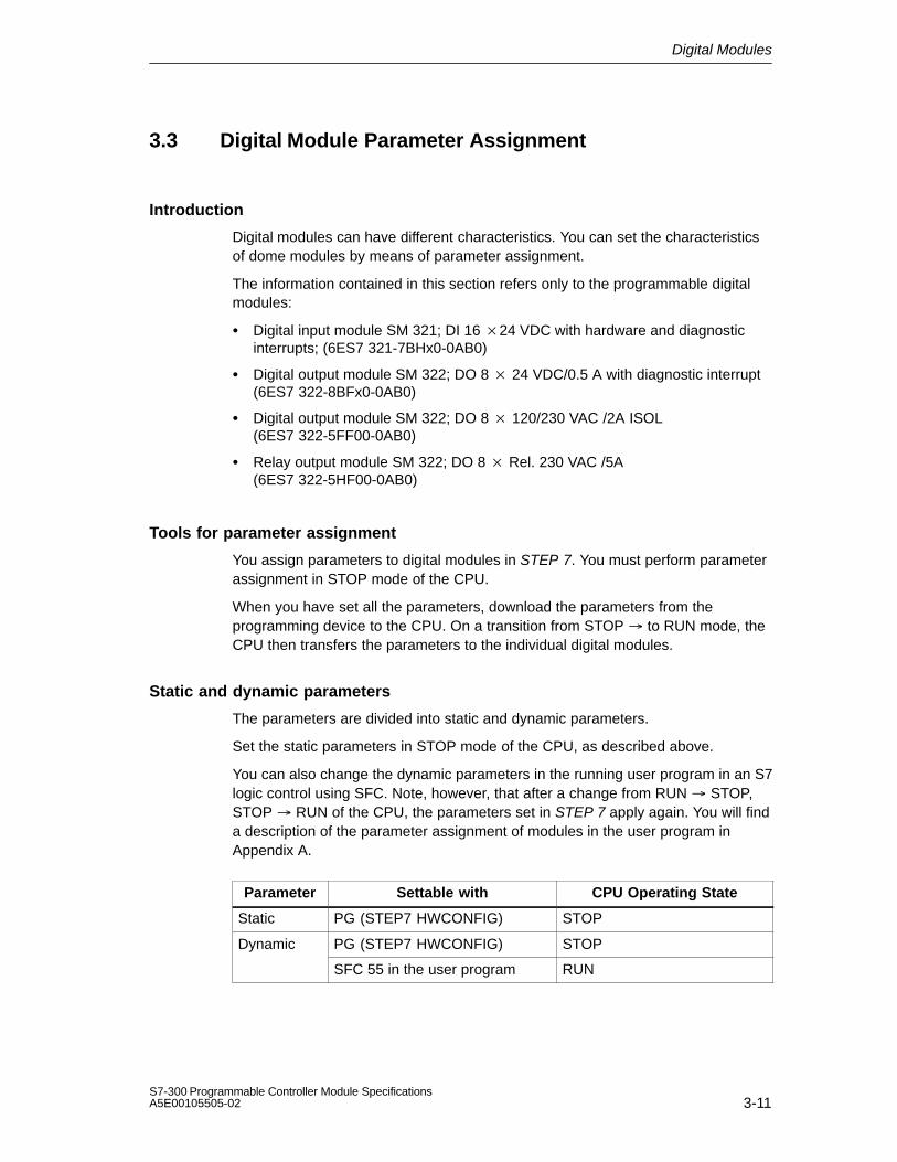
Digital Modules
3-11S7-300 Programmable Controller Module SpecificationsA5E00105505-02
3.3 Digital Module Parameter Assignment
Introduction
Digital modules can have different characteristics. You can set the characteristicsof dome modules by means of parameter assignment.
The information contained in this section refers only to the programmable digitalmodules:
Digital input module SM 321; DI 16 24 VDC with hardware and diagnosticinterrupts; (6ES7 321-7BHx0-0AB0)
Digital output module SM 322; DO 8 24 VDC/0.5 A with diagnostic interrupt(6ES7 322-8BFx0-0AB0)
Digital output module SM 322; DO 8 120/230 VAC /2A ISOL(6ES7 322-5FF00-0AB0)
Relay output module SM 322; DO 8 Rel. 230 VAC /5A(6ES7 322-5HF00-0AB0)
Tools for parameter assignment
You assign parameters to digital modules in STEP 7. You must perform parameterassignment in STOP mode of the CPU.
When you have set all the parameters, download the parameters from theprogramming device to the CPU. On a transition from STOP to RUN mode, theCPU then transfers the parameters to the individual digital modules.
Static and dynamic parameters
The parameters are divided into static and dynamic parameters.
Set the static parameters in STOP mode of the CPU, as described above.
You can also change the dynamic parameters in the running user program in an S7logic control using SFC. Note, however, that after a change from RUN STOP,STOP RUN of the CPU, the parameters set in STEP 7 apply again. You will finda description of the parameter assignment of modules in the user program inAppendix A.
Parameter Settable with CPU Operating State
Static PG (STEP7 HWCONFIG) STOP
Dynamic PG (STEP7 HWCONFIG) STOP
SFC 55 in the user program RUN

Digital Modules
3-12S7-300 Programmable Controller Module Specifications
A5E00105505-02
Parameters of the digital modules
The settable parameters are listed in the special section on the module.
3.4 Diagnostics of the Digital Modules
Introduction
The information contained in this section refers only to the digital modules withdiagnostics capability. For the S7-300, these modules are as follows:
Digital input module SM 321; DI 1624 VDC with hardware and diagnosticinterrupts; (6ES7 321-7BHx0-0AB0)
Digital output module SM 322; DO 8 24 VDC/0.5 A with diagnostic interrupt(6ES7 322-8BFx0-0AB0)
Digital output module SM 322; DO 8 120/230 VAC /2A ISOL(6ES7 322-5FF00-0AB0)
Relay output module SM 322; DO 8 Rel. 230 VAC /5A(6ES7 322-5HF00-0AB0)
Programmable and non-programmable diagnostic messages
In diagnostics, we make a distinction between programmable andnon-programmable diagnostic messages.
You obtain programmable diagnostic messages only if you have enableddiagnostics by parameter assignment. You perform parameter assignment in the”Diagnostics” parameter field in STEP 7.
Non-programmable diagnostic messages are always made available by the digitalmodule irrespective of diagnostics being enabled.
Actions following diagnostic message in STEP 7
Each diagnostic message leads to the following actions:
The diagnostic message is entered in the diagnosis of the digital module andforwarded to the CPU.
The SF LED on the digital module lights.
If you have programmed ”Enable Diagnostic Interrupt” in STEP 7, a diagnosticinterrupt is triggered and OB 82 is called.
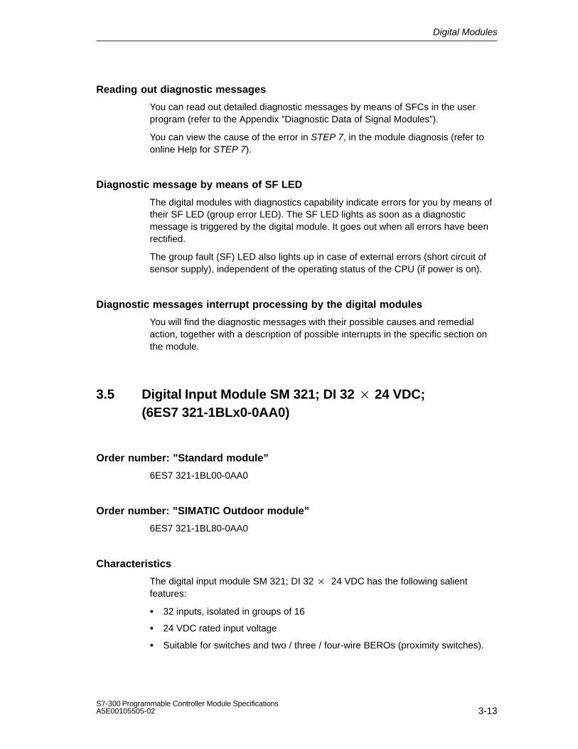
Digital Modules
3-13S7-300 Programmable Controller Module SpecificationsA5E00105505-02
Reading out diagnostic messages
You can read out detailed diagnostic messages by means of SFCs in the userprogram (refer to the Appendix ”Diagnostic Data of Signal Modules”).
You can view the cause of the error in STEP 7, in the module diagnosis (refer toonline Help for STEP 7).
Diagnostic message by means of SF LED
The digital modules with diagnostics capability indicate errors for you by means oftheir SF LED (group error LED). The SF LED lights as soon as a diagnosticmessage is triggered by the digital module. It goes out when all errors have beenrectified.
The group fault (SF) LED also lights up in case of external errors (short circuit ofsensor supply), independent of the operating status of the CPU (if power is on).
Diagnostic messages interrupt processing by the digital modules
You will find the diagnostic messages with their possible causes and remedialaction, together with a description of possible interrupts in the specific section onthe module.
3.5 Digital Input Module SM 321; DI 32 24 VDC;(6ES7 321-1BLx0-0AA0)
Order number: ”Standard module”
6ES7 321-1BL00-0AA0
Order number: ”SIMATIC Outdoor module”
6ES7 321-1BL80-0AA0
Characteristics
The digital input module SM 321; DI 32 24 VDC has the following salientfeatures:
32 inputs, isolated in groups of 16
24 VDC rated input voltage
Suitable for switches and two / three / four-wire BEROs (proximity switches).

Digital Modules
3-14S7-300 Programmable Controller Module Specifications
A5E00105505-02
Terminal assignment and block diagram of the SM 321; DI 32 24 VDC
Channelnumber
Status display -green
Backplane businterface
24V 24V
Figure 3-1 Module View and Block Diagram of the Digital Input Module SM 321; DI 3224 VDC
Terminal assignment of the SM 321; DI 32 24 VDC
The following figure shows the assignment of the channels to the addresses.
Input byte x
Input byte (x+1)
Input byte (x+2)
Input byte (x+3)
Figure 3-2 Terminal assignment of the SM 321; DI 32 24 VDC

Digital Modules
3-15S7-300 Programmable Controller Module SpecificationsA5E00105505-02
Technical specifications of the SM 321; DI 32 24 VDC
Dimensions and Weight
Dimensions W H D (in millimeters)
40 125 120
Weight Approx. 260 g
Data for Specific Module
Supports clocked operation
No
Number of inputs 32
Length of cable
Unshielded
Shielded
max. 600 m
max. 1000 m
Voltages, Currents, Potentials
Number of inputs that can betriggered simultaneously
Horizontal configuration
Up to 40 C
Up to 60 C
Vertical configuration
Up to 40 C
32
16
32
Isolation
Between channels andbackplane bus
Between the channels In groups of
Yes
Yes16
Permitted potential difference
Between the differentcircuits
75 VDC / 60 VAC
Insulation tested with 500 VDC
Current consumption
From the backplane bus max. 15 mA
Power dissipation of the module typ. 6.5 W
Status, Interrupts, Diagnostics
Status display Green LED per channel
Interrupts None
Diagnostic functions None
Data for Selecting a Sensor
Input voltage
Rated value
For signal ”1”
For signal ”0”
24 VDC
13 to 30 V
–30 to + 5 V
Input current
At signal ”1” typ. 7 mA
Input delay
At ”0” to ”1”
At ”1” to ”0”
1.2 to 4.8 ms
1.2 to 4.8 ms
Input characteristic curve According to IEC61131, type 1
Connection of Two-WireBEROs
Permitted bias current
Possible
max. 1.5 mA

Digital Modules
3-16S7-300 Programmable Controller Module Specifications
A5E00105505-02
3.6 Digital Input Module SM 321; DI 32 120 VAC; (6ES7 321-1EL00-0AA0)
Order number
6ES7 321-1EL00-0AA0
Characteristics
The SM 321; DI 32 120 VAC features the following characteristics:
32 inputs, isolated in groups of 8
120 VAC rated input voltage
Suitable for switches and two / three-wire AC proximity switches
Terminal assignment and block diagram of the SM 321; DI 32 120 VAC
Channelnumber
Status display -green
1 L
L
L
L2
3
4
1 N
2 N
3 N
4 N
Back-plane
bus inter-face
Figure 3-3 Module View and Block Diagram of Digital Input Module SM 321; DI 32 120 VAC

Digital Modules
3-17S7-300 Programmable Controller Module SpecificationsA5E00105505-02
Technical specifications of the SM 321; DI 32 120 VAC
Dimensions and Weight
Dimensions WHD (in millimeters)
40125117
Weight Approx. 300 g
Data for Specific Module
Supports clocked operation
No
Number of inputs 32
Length of cable
Unshielded
Shielded
max. 600 m
max. 1000 m
Voltages, Currents, Potentials
Number of inputs that can betriggered simultaneously
Horizontal configuration
Up to 40 C 32
Up to 60 C 24
Vertical configuration
Up to 40 C 32
Isolation
Between channels andbackplane bus
Yes
Between the channels Yes
In groups of 8
Permitted potential difference
Between Minternal and theinputs
120 VAC
Between the inputs of thedifferent groups
250 VAC
Insulation tested with 2500 VDC
Current consumption
From the backplane bus max. 16 mA
Power dissipation of the module typ. 4 W
Status, Interrupts, Diagnostics
Status display Green LED per channel
Interrupts None
Diagnostic functions None
Data for Selecting a Sensor
Input voltage
Rated value
For ‘‘1’’ signal
For ‘‘0’’ signal
Frequency range
120 VAC
74 to 132 V
0 to 20 V
47 to 63 Hz
Input current
At ‘‘1’’ signal typ. 21 mA
Input delay
From ‘‘0’’ to ‘‘1’’
From ‘‘1’’ to ‘‘0’’
max. 15 ms
max. 25 ms
Input characteristic curve According to IEC61131, type 2
Connection of Two-WireBEROs
Permitted bias current
Possible
max. 4 A

Digital Modules
3-18S7-300 Programmable Controller Module Specifications
A5E00105505-02
3.7 Digital Input Module SM 321; DI 16 24 VDC; (6ES7 321-1BHx2-0AA0)
Order number: ”Standard module”
6ES7 321-1BH02-0AA0
Order number: ”SIMATIC Outdoor module”
6ES7 321-1BH82-0AA0
Characteristics
The digital input module SM 321; DI 16 24 VDC has the following salientfeatures:
16 inputs, isolated in groups of 16
24 VDC rated input voltage
Suitable for switches and two / three / four-wire BEROs (proximity switches).

Digital Modules
3-19S7-300 Programmable Controller Module SpecificationsA5E00105505-02
Terminal assignment and block diagram of the SM 321; DI 16 24 VDC
Status display – green
Channel number
Backplane bus interface
M24 V
Figure 3-4 Module View and Block Diagram of Digital Input Module SM 321; DI 16 24VDC

Digital Modules
3-20S7-300 Programmable Controller Module Specifications
A5E00105505-02
Technical specifications of the SM 321; DI 16 24 VDC
Dimensions and Weight
Dimensions W H D (in millimeters)
40 125 117
Weight Approx. 200 g
Data for Specific Module
Supports clocked operation
No
Number of inputs 16
Length of cable
Unshielded
Shielded
max. 600 m
max. 1000 m
Voltages, Currents, Potentials
Number of inputs that can betriggered simultaneously
Horizontal configuration
Up to 60 C
Vertical configuration
Up to 40 C
16
16
Isolation
Between channels andbackplane bus
Yes
Permitted potential difference
Between the differentcircuits
75 VDC / 60 VAC
Insulation tested with 500 VDC
Current consumption
From the backplane bus max. 10 mA
Power dissipation of the module typ. 3.5 W
Status, Interrupts, Diagnostics
Status display Green LED per channel
Interrupts None
Diagnostic functions None
Data for Selecting a Sensor
Input voltage
Rated value
For signal ”1”
For signal ”0”
24 VDC
13 to 30 V
–30 to + 5 V
Input current
At signal ”1” typ. 7 mA
Input delay
At ”0” to ”1”
At ”1” to ”0”
1.2 to 4.8 ms
1.2 to 4.8 ms
Input characteristic curve According to IEC61131, type 1
Connection of Two-WireBEROs
Permitted bias current
Possible
max. 1.5 mA

Digital Modules
3-21S7-300 Programmable Controller Module SpecificationsA5E00105505-02
3.8 Digital Input Module SM 321; DI 16 24 VDC High Speed; (6ES7 321-1BH10-0AA0)
Order number:
6ES7 321-1BH10-0AA0
Characteristics
The SM 321; DI 16 24 VDC High Speed has the following salient features:
16 inputs, isolated in groups of 16
24 VDC rated input voltage
Suitable for switches and two / three / four-wire BEROs (proximity switches).
Supports clocked operation
Terminal assignment and block diagram of the SM 321; DI 16 24 VDC HighSpeed
Status display – green
Channel number
Backplane bus interface
M24 V
Figure 3-5 Module View and Block Diagram of the SM 321; DI 16 24 VDC High Speed

Digital Modules
3-22S7-300 Programmable Controller Module Specifications
A5E00105505-02
Technical specifications of the SM 321; DI 16 24 VDC High Speed
Dimensions and Weight
Dimensions W H D (in millimeters)
40 125 117
Weight Approx. 200 g
Data for Specific Module
Supports clocked operation
Yes
Number of inputs 16
Length of cable
Unshielded
Shielded
max. 600 m
max. 1000 m
Voltages, Currents, Potentials
Number of inputs that can betriggered simultaneously
Horizontal configuration
Up to 60 C
Vertical configuration
Up to 40 C
16
16
Isolation
Between channels andbackplane bus
Yes
Permitted potential difference
Between the differentcircuits
75 VDC / 60 VAC
Insulation tested with 500 VDC
Current consumption
From the backplane bus max. 110 mA
Power dissipation of the module typ. 3.8 W
Status, Interrupts, Diagnostics
Status display Green LED per channel
Interrupts None
Diagnostic functions None
Data for Selecting a Sensor
Input voltage
Rated value
For signal ”1”
For signal ”0”
24 VDC
13 to 30 V
–30 to + 5 V
Input current
At signal ”1” typ. 7 mA
Input delay
At ”0” to ”1”
At ”1” to ”0”
25 to 75 s
25 to 75 s
Input characteristic curve According to IEC61131, type 1
Connection of Two-WireBEROs
Permitted bias current
Possible
max. 1.5 mA

Digital Modules
3-23S7-300 Programmable Controller Module SpecificationsA5E00105505-02
3.9 Digital Input Module SM 321; DI 16 24 VDC; withHardware and Diagnostic interrupts; (6ES7 321-7BHx0-0AB0)
Order number: ”Standard module”
6ES7 321-7BH00-0AB0
Order number: ”SIMATIC Outdoor module”
6ES7 321-7BH80-0AB0
Characteristics
The SM 321; DI 16 24 VDC; with hardware and diagnostic interrupts featuresthe following characteristics:
16 inputs, isolated in groups of 16
24 VDC rated input voltage
Input characteristic curve according to IEC 61131, Type 2
Suitable for switches and two / three / four-wire BEROs (proximity switches).
2 short-circuit-proof sensor supplies for 8 channels each
External redundant power supply possible to supply sensors
”Sensor supply (Vs)” status display
Group error display
Programmable diagnostics
Programmable diagnostic interrupt
Programmable hardware interrupt
Programmable input delays

Digital Modules
3-24S7-300 Programmable Controller Module Specifications
A5E00105505-02
Terminal assignment of the SM 321; DI 16 24 VDC
Status display – greenChannel number
Backplane businterface
L+
M
M24 V
SF
Vs
Vs
Encoder supplies Vs - green
M
M
L+
Vs
Vs
L +
Fault indicator – red
Figure 3-6 Module View and Block Diagram of the SM 321; DI 16 24 VDC (6ES7 321-7BHx0-0AB0)
Terminal assignment for redundant supply of encoders
The figure below shows how encoder can additionally be supplied by means of Vswith a redundant voltage source – for example, via another module).
Vs
M
L+ 1 L+
2 L+
to the sensors
Digital inputmodule
Short-circuit-proof driver
Figure 3-7 Terminal Assignment for the Redundant Supply of Encoders of the SM 321;DI 16 24 VDC (6ES7 321-7BHx0-0AB0)

Digital Modules
3-25S7-300 Programmable Controller Module SpecificationsA5E00105505-02
Technical specifications of the SM 321; DI 16 24 VDC
Dimensions and Weight
Dimensions W H D (in millimeters)
40 125 117
Weight Approx. 200 g
Data for Specific Module
Supports clocked operation
No
Number of inputs 16
Length of cable
Unshielded
Shielded
max. 600 m
max. 1000 m
Voltages, Currents, Potentials
Power rated voltage of theelectronics and encoder L+
24 VDC
Reverse polarity protection Yes
Number of inputs that can be triggered simultaneously
Horizontal configuration
Up to 60 C 16
Vertical configuration
Up to 40 C 16
Isolation
Between channels andbackplane bus
Yes
Permitted potential difference
Between the differentcircuits
75 VDC / 60 VAC
Insulation tested with 500 VDC
Current consumption
From the backplane bus max. 55 mA
From load voltage L +(without sensor supply VS)
max. 40 mA
Power dissipation of the module typ. 4 W
Status, Interrupts, Diagnostics
Status display
Inputs Green LED per channel
Sensor power supplies (Vs) Green LED per output
Interrupts
Hardware interrupt
Diagnostic Interrupt
Parameters can beassigned
Parameters can beassigned
Diagnostic functions Parameters can beassigned
Group error display Red LED (SF)
Diagnostics informationread-out
Possible
Sensor Power Supply Outputs
Number of outputs 2
Output voltage
With load min. L+ (–2.5 V)
Output current
Rated value
Permitted range
120 mA
0 to 150 mA
Additional (redundant) supply Permitted
Short-circuit protection Yes, electronic
Data for Selecting a Sensor
Input voltage
Rated value
For signal ”1”
For signal ”0”
24 VDC
13 to 30 V
30 to + 5 V
Input current
At signal ”1” typ. 7 mA
Input characteristic curve According to IEC61131, type 2
Connection of Two-WireBEROs
Permitted bias current
Possible
max. 2 mA
Time/Frequency
Internal preparation time for
Only interrupt processing
Interrupt and diagnosticsprocessing
max. 250 s
max. 250 s
Input delay
Parameters can beassigned
Rated value
Yes
typ. 0.1/0.5/3/15/20 ms
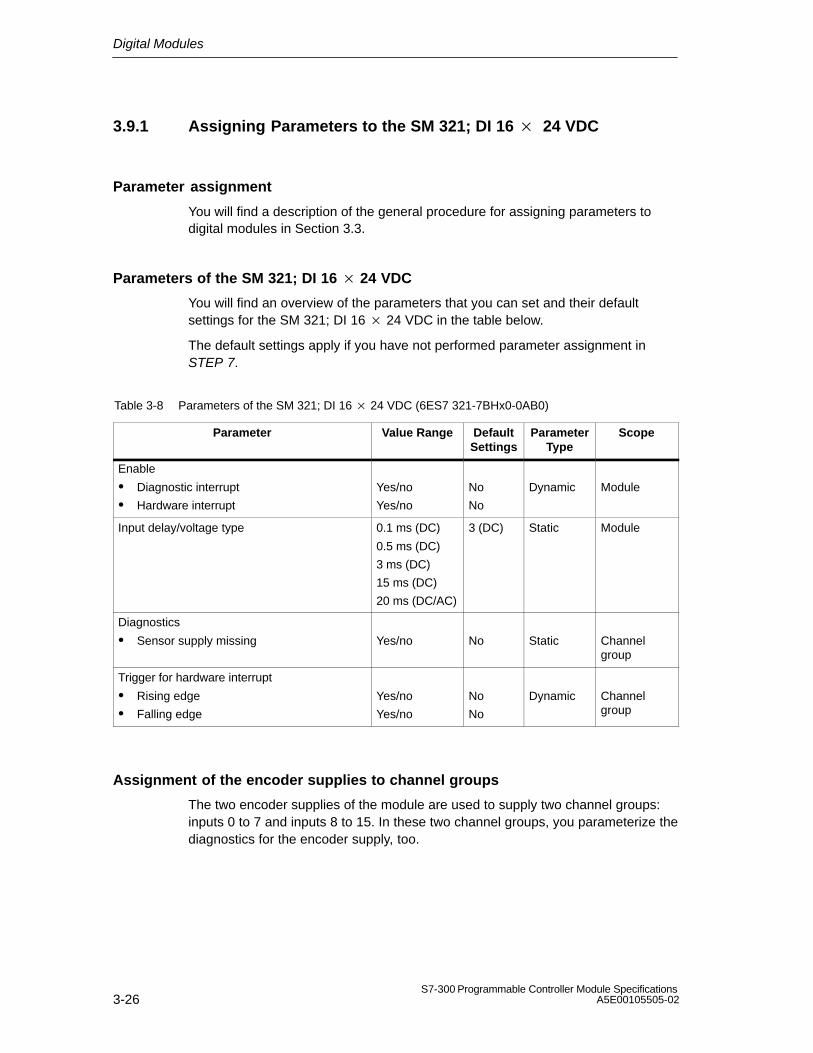
Digital Modules
3-26S7-300 Programmable Controller Module Specifications
A5E00105505-02
3.9.1 Assigning Parameters to the SM 321; DI 16 24 VDC
Parameter assignment
You will find a description of the general procedure for assigning parameters todigital modules in Section 3.3.
Parameters of the SM 321; DI 16 24 VDC
You will find an overview of the parameters that you can set and their defaultsettings for the SM 321; DI 16 24 VDC in the table below.
The default settings apply if you have not performed parameter assignment inSTEP 7.
Table 3-8 Parameters of the SM 321; DI 16 24 VDC (6ES7 321-7BHx0-0AB0)
Parameter Value Range DefaultSettings
ParameterType
Scope
Enable
Diagnostic interrupt
Hardware interrupt
Yes/no
Yes/no
No
No
Dynamic Module
Input delay/voltage type 0.1 ms (DC)
0.5 ms (DC)
3 ms (DC)
15 ms (DC)
20 ms (DC/AC)
3 (DC) Static Module
Diagnostics
Sensor supply missing Yes/no No Static Channelgroup
Trigger for hardware interrupt
Rising edge
Falling edge
Yes/no
Yes/no
No
No
Dynamic Channelgroup
Assignment of the encoder supplies to channel groups
The two encoder supplies of the module are used to supply two channel groups:inputs 0 to 7 and inputs 8 to 15. In these two channel groups, you parameterize thediagnostics for the encoder supply, too.
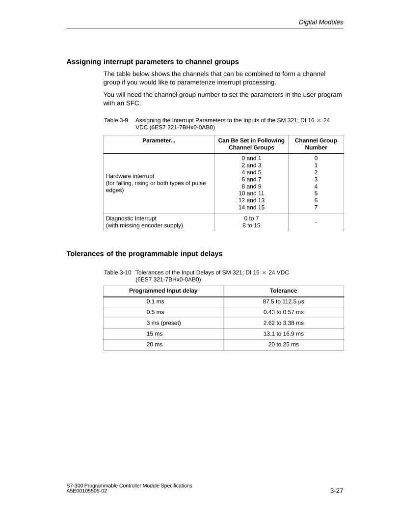
Digital Modules
3-27S7-300 Programmable Controller Module SpecificationsA5E00105505-02
Assigning interrupt parameters to channel groups
The table below shows the channels that can be combined to form a channelgroup if you would like to parameterize interrupt processing.
You will need the channel group number to set the parameters in the user programwith an SFC.
Table 3-9 Assigning the Interrupt Parameters to the Inputs of the SM 321; DI 16 24VDC (6ES7 321-7BHx0-0AB0)
Parameter... Can Be Set in FollowingChannel Groups
Channel GroupNumber
Hardware interrupt(for falling, rising or both types of pulseedges)
0 and 12 and 34 and 56 and 78 and 9
10 and 1112 and 1314 and 15
01234567
Diagnostic Interrupt(with missing encoder supply)
0 to 78 to 15
-
Tolerances of the programmable input delays
Table 3-10 Tolerances of the Input Delays of SM 321; DI 16 24 VDC(6ES7 321-7BHx0-0AB0)
Programmed Input delay Tolerance
0.1 ms 87.5 to 112.5 s
0.5 ms 0.43 to 0.57 ms
3 ms (preset) 2.62 to 3.38 ms
15 ms 13.1 to 16.9 ms
20 ms 20 to 25 ms

Digital Modules
3-28S7-300 Programmable Controller Module Specifications
A5E00105505-02
3.9.2 Behavior and Diagnostics of the SM 321; DI 16 24 VDC
Effect of operating and mode supply voltage on the input values
The input values of the SM 321; DI 16 24 DC depend on the operating mode ofthe CPU and on the supply voltage of the module.
Table 3-11 Dependencies of Input Values on the Operating Mode of the CPU and SupplyVoltage L+ of the SM 321; DI 16 24 VDC (6ES7 321-7BHx0-0AB0)
CPU Operating State Power Supply L+to Digital Module
Input Value of DigitalModule
POWER ON RUN L+ exists Process value
L+ missing 0 signal
STOP L+ exists Process value
L+ missing 0 signal
POWER OFF – L+ exists –
L+ missing –
Diagnostic Messages of the SM 321; DI 16 24 VDC
The table below presents an overview of the diagnostic messages for the SM 321;DI 16 24 VDC.
Table 3-12 Diagnostic Messages of the SM 321; DI 16 24 VDC(6ES7 321-7BHx0-0AB0)
Diagnostics Message LED Scope of the Diagnostics
Parameterscan be assi-
gned
Sensor supply missing SF Channel group Yes
External auxiliary supply missing SF Module
Internal auxiliary power missing SF Module
Fuse blown SF Module
Incorrect parameter on module SF Module
Watchdog timeout SF ModuleNo
EPROM error SF Module
RAM error SF Module
Hardware interrupt lost SF Module

Digital Modules
3-29S7-300 Programmable Controller Module SpecificationsA5E00105505-02
Note
A prerequisite for detecting the errors indicated by programmable diagnosticmessages is that you have assigned parameters to the digital module accordinglyin STEP 7.
Behavior upon failure of the supply voltage
A failure of the supply voltage of the SM 321; DI 16 24 DC is always indicatedby the SF LED on the module. Furthermore, this information is made available onthe module.
The input value is initially held for 20 to 40 ms before the 0 signal is transferred tothe CPU. Supply voltage dips < 20 ms do not modify the process value (refer toTable 3-11).
Triggering of the diagnostic interrupt depends on the parameter assignment (seeSection 3.9.3).
Failure of the supply voltage with redundant encoder incoming supply
Note
If an external redundant source is applied simultaneously to the sensor supply(Vs), a failure in the internal sensor supply causes a failure of the internal and/orexternal sensor supply and/or a blown fuse to be indicated instead of a regularsensor supply failure.
Short-circuit of sensor supply Vs
Irrespective of the parameter assignment, the corresponding Vs LED goes out if ashort-circuit of the encoder supply Vs occurs.

Digital Modules
3-30S7-300 Programmable Controller Module Specifications
A5E00105505-02
Causes of error and remedial measures
Table 3-13 Diagnostic Messages of the SM 321; DI 16 24 VDC (6ES7 321-7BHx0-0AB0), Causes ofError and Remedial Measures
DiagnosticsMessage
Possible Error Cause Remedy
Lack of encoder Overload of sensor supply Eliminate overloadsupply
Short circuit of sensor supply to M Eliminate short circuit
External auxiliaryvoltage missing
Power supply L+ to module missing Feed supply L+
Internal auxiliary Power supply L+ to module missing Feed supply L+voltage missing
Fuse in module defective Replace module
Fuse blown Fuse in module defective Replace module
Wrong parameters inmodule
One parameter or the combination ofparameters is not plausible
Reassign module parameter
Watchdog tripped Temporary high electromagneticinterference
Eliminate interference
Module defective Replace module
EPROM error Temporary high electromagneticinterference
Eliminate interference and switch on/offpower supply of CPU
Module defective Replace module
RAM error Temporary high electromagneticinterference
Eliminate interference and switch on/offpower supply of CPU
Module defective Replace module
Hardware interrupt lost The module cannot send an interrupt,since the previous interrupt was notacknowledged; configuration errorpossible
Change interrupt processing in CPUand reconfigure module parameters, ifrequired
The error continues until the module isconfigured with new parameters

Digital Modules
3-31S7-300 Programmable Controller Module SpecificationsA5E00105505-02
3.9.3 Interrupts of the SM 321; DI 16 24 VDC
Introduction
This section describes the SM 321; DI 16 24 VDC with regard to its interruptbehavior. The following interrupts exist:
Diagnostic Interrupt
Hardware interrupt
The OBs and SFCs mentioned below can be found in the online Help for STEP 7,where they are described in greater detail.
Enabling interrupts
The interrupts are not preset – in other words, they are inhibited withoutappropriate parameter assignment. Assign parameters to the Interrupt Enable inSTEP 7 (refer to Section 3.9.1).
Diagnostic interrupt
If you have enabled diagnostic interrupts, then active error events (initialoccurrence of the error) and departing error events (message aftertroubleshooting) are reported by means of an interrupt.
The CPU interrupts the execution of the user program and processes thediagnostic interrupt block (OB 82).
In the user program, you can call SFC 51 or SFC 59 in OB 82 to obtain moredetailed diagnostic information from the module.
The diagnostic information is consistent until such time as OB 82 is exited. WhenOB 82 is exited, the diagnostic interrupt is acknowledged on the module.

Digital Modules
3-32S7-300 Programmable Controller Module Specifications
A5E00105505-02
Hardware interrupt
The SM 321; DI 16 24 VDC can trigger a hardware interrupt for every channelgroup with a rising or falling edge, or both, of a signal status change.
Perform parameter assignment one channel group at a time. It can be modified atany time (in RUN mode using the user program).
Pending hardware interrupts trigger hardware interrupt processing in the CPU(OB 40). The CPU interrupts the execution of the user program or of the priorityclasses with low priority.
You can set in the user program of the hardware interrupt OB (OB 40) how theprogrammable logic controller has to react to an edge change. When the hardwareinterrupt OB is exited, the hardware interrupt is acknowledged on the module.
The module can buffer one interrupt per channel. If no higher priority run-timelevels are waiting to be processed, the buffered interrupts (of all modules) areserviced one after the other by the CPU according to the order in which theyoccurred.
Hardware interrupt lost
In an interrupt has been buffered for a channel and another interrupt occurs on thatchannel before it has been processed by the CPU, a diagnostic interrupt ”hardwareinterrupt lost” is triggered.
More interrupts on this channel are not acquired until processing of the interruptbuffered on this channel has been executed.
Interrupt-triggering channels
The interrupt-triggering channels are stored in the local data of the hardwareinterrupt OBs (in the OB start information). The start information is two words long(bits 0 to 31). The bit number is the channel number. Bits 16 to 31 are notassigned.

Digital Modules
3-33S7-300 Programmable Controller Module SpecificationsA5E00105505-02
3.10 Digital Input Module SM 321; DI 16 DC 24 V; Source Input; (6ES7 321-1BH50-0AA0)
Order number
6ES7 321-1BH50-0AA0
Characteristics
The SM 321; DI 16 24 VDC (source input) has the following salient features:
16 inputs, source input, isolated in groups of 16
24 VDC rated input voltage
Suitable for switches and two- / three- / four-wire BEROs (proximity switches).
Terminal assignment and block diagram of the SM 321; DI 16 24 VDC
Channel number
Status display – green
Backplane businterface
L +
Figure 3-8 Module View and Block Diagram of Digital Input Module SM 321; DI 16 24 VDC (Source Input)

Digital Modules
3-34S7-300 Programmable Controller Module Specifications
A5E00105505-02
Technical specifications of the SM 321; DI 16 24 VDC
Dimensions and Weight
Dimensions W H D(in millimeters)
40 125 117
Weight Approx. 200 g
Data for Specific Module
Supports clocked operation
No
Number of inputs 16
Length of cable
Unshielded
Shielded
max. 600 m
max. 1000 m
Voltages, Currents, Potentials
Number of inputs that can betriggered simultaneously
Horizontal configuration
Up to 60 C 16
Vertical configuration
Up to 40 C 16
Isolation
Between channels andbackplane bus
Yes
Permitted potential difference
Between the differentcircuits
75 VDC / 60 VAC
Insulation tested with 500 VDC
Current consumption
From the backplane bus max. 10 mA
Power dissipation of themodule
typ. 3.5 W
Status, Interrupts, Diagnostics
Status display Green LED per channel
Interrupts None
Diagnostic functions None
Data for Selecting a Sensor
Input voltage (reference potential is L+)
Rated value
For signal ”1”
For signal ”0”
24 VDC
–13 V to –30 V
+30 V to –5 V
Input current
At signal ”1” typ. 7 mA
Input delay
At ”0” to ”1”
At ”1” to ”0”
1.2 to 4.8 ms
1.2 to 4.8 ms
Input characteristic curve According to IEC 61131,type 1
Connection of Two-WireBEROs
Permitted bias current
Possible
max. 1.5 mA

Digital Modules
3-35S7-300 Programmable Controller Module SpecificationsA5E00105505-02
3.11 Digital Input Module SM 321; DI 16 × UC 24/48 V(6ES7 321-1CH00-0AA0)
Order number
6ES7 321-1CH00-0AA0
Characteristics
The SM 321; DI 16 × UC24/48 V features the following characteristics:
16 inputs, isolated electrically
Electrical isolation between channels of 120 V
Rated input voltage from 24 to 48 DC)
Inputs are fully independent and can be connected in any required configuration
Terminal assignment and block diagram of the SM 321; DI 16 24/48 VUC
3
1
2
0
3
1
2
0
7
5
6
4
7
5
6
4
87
10
9
6
2
54
1
3837
40
39
36
32
3534
31
2827
30
29
26
22
2524
21
1817
20
19
16
13
12
1514
11
3 23
33
Backplane bus interface
Status display – green
Channel number
Figure 3-9 Module View and Block Diagram of Digital Input Module SM 321; DI 16 24/48VUC

Digital Modules
3-36S7-300 Programmable Controller Module Specifications
A5E00105505-02
Technical specifications of the SM 321; DI 16 24/48 VUC
Dimensions and Weight
Dimensions W × H × D 40 × 125 × 117
Weight Approx. 260 g
Data for Specific Module
Supports clocked operation
No
Number of inputs 16
Length of cable
Unshielded
Shielded
max. 600 m
max. 1000 m
Voltages, Currents, Potentials
Number of inputs that can betriggered simultaneously
Horizontal configurationup to 60°C
16
All other configuration typesup to 40° C
16
Isolation
Between channels andbackplane bus
Yes
Between channels
In groups of
Yes
1
Permitted potential difference
Between the channels andthe backplane bus
170 VDC, 120 VAC
Between the inputs of thedifferent groups
170 VDC, 120 VAC
Insulation tested with
Between the channels andthe backplane bus
1500 VAC
Between the inputs of thedifferent groups
1500 VAC
Current consumption
From the backplane bus max. 100 mA
Power dissipation of the module
Operation with 24 V
Operation with 48 V
typ. 1.5 W
typ. 2.8 W
Status, Interrupts, Diagnostics
Status display
Interrupts
Diagnostic functions
Green LEDs perchannel
None
None
Data for Selecting a Sensor
Input voltage
Rated value 24 or 48 VDC/ 24 or 48VAC
At signal ”1”
At signal ”0”
Frequency range
14 V to 60 V
-5 V to 5 V
0 to 63 Hz
Input current
At signal ”1”
At signal ”0”
typ. 2.7 mA
-1 to +1 mA
Input delay
At ”0” to ”1”
At ”1” to ”0”
max. 16 ms
max. 16 ms
Input characteristic curve According to IEC61131, type 1
Connection of Two-WireBEROs
Possible
Permitted bias current max. 1 mA

Digital Modules
3-37S7-300 Programmable Controller Module SpecificationsA5E00105505-02
3.12 Digital Input Module SM 321; DI 16 48-125 VDC;(6ES7 321-1CH80-0AA0)
Order number: ”SIMATIC Outdoor module”
6ES7 321-1CH80-0AA0
Characteristics
The SM 321; DI 16 48-125 VDC features the following characteristics:
16 inputs, isolated in groups of 8
Rated input voltage 48 to 125 VDC
Suitable for switches and two / three / four-wire BEROs (proximity switches).
Terminal assignment and block diagram of the SM 321; DI 16 48-125 VDC
Status display – green
Channel number
Backplane businterface
M
2M
48 to 125 V
M
1M
48 to 125 V
12
13141516
1718
1920
2
34
567
89
10
Figure 3-10 Module View and Block Diagram of SM 321; DI 16 48-125 VDC

Digital Modules
3-38S7-300 Programmable Controller Module Specifications
A5E00105505-02
Technical specifications of the SM 321; DI 16 48-125 VDC
Dimensions and Weight
Dimensions W H D(in millimeters)
40 125 120
Weight Approx. 200 g
Data for Specific Module
Supports clocked operation
No
Number of inputs 16
Length of cable
Unshielded
Shielded
max. 600 m
max. 1000 m
Voltages, Currents, Potentials
Number of inputs that can betriggered simultaneously at UE Up to 60 V Up to 146
V
Horizontal installation
Up to 50 C
Up to 60 C
8 8
8 6
Vertical configuration
Up to 40 C 8 8
Isolation
Between channels andbackplane bus
Yes
Between the channels
In groups of
Yes
8
Permiss. potential differences
Between the differentcircuits
146 VDC / 132 VAC
Insulation tested with 1500 VDC
Current consumption
From the backplane bus max. 40 mA
Power dissipation of the module typ. 4.3 W
Status, Interrupts, Diagnostics
Status display Green LED per channel
Interrupts None
Diagnostic functions None
Sensor Selection Data
Input voltage
Rated value 48 VDC to 125 VDC
For signal ”1” 30 V to 146 V
For signal ”0” -146 V to 15 V
Input current
At signal ”1” typ. 3.5 mA
Input delay
At ”0” to ”1”
At ”1” to ”0”
0.1 ms to 3.5 ms
0.7 ms to 3.0 ms
Input characteristic curve According to IEC61131, type 1
Connection of Two-WireBEROs
Permitted bias current
Possible
max. 1 mA

Digital Modules
3-39S7-300 Programmable Controller Module SpecificationsA5E00105505-02
3.13 Digital Input Module SM 321; DI 16AC 120/230 V (6ES7 321-1FH00-0AA0)
Order number
6ES7 321-1FH00-0AA0
Characteristics
The SM 321; DI 16 × 120/230 VAC features the following characteristics:
16 inputs, electrically isolated in groups of 4
120/230 VAC rated input voltage
Suitable for switches and two / three-wire proximity switches (alternatingvoltage)
Terminal assignment and block diagram of the SM 321; DI 16 x 120/230 VAC
Channel number
Status display – green
M
N
N
N
M
M
M
Backplane businterface
N
Figure 3-11 Module View and Block Diagram of the SM 321; DI 16 × 120/230 VAC

Digital Modules
3-40S7-300 Programmable Controller Module Specifications
A5E00105505-02
Technical specifications of the SM 321; DI 16 x 120/230 VAC
Dimensions and Weight
Dimensions W × H × D(in millimeters)
40 × 125 × 117
Weight Approx. 240 g
Data for Specific Module
Supports clocked operation
No
Number of inputs 16
Length of cable
Unshielded
Shielded
max. 600 m
max. 1000 m
Voltages, Currents, Potentials
Rated load voltage L1
All load voltages must be of thesame phase
120/230 V
Number of inputs that can betriggered simultaneously
Horizontal configurationUp to 60 °C
16
Vertical configurationUp to 40 °C
16
Isolation
Between channels andbackplane bus
Yes
Between channels
In groups of
Yes
4
Permitted potential difference
Between Minternal and theinputs
500 VAC
Between the inputs of thedifferent groups
230 VAC
Insulation tested with 4000 VDC
Current consumption
From the backplane bus max. 29 mA
Power dissipation of the module typ. 4.9 W
Status, Interrupts, Diagnostics
Status display Green LED per channel
Interrupts None
Diagnostic functions None
Sensor Selection Data
Input voltage
Rated value
For signal ”1”
For signal ”0”
Frequency range
120/230 VAC
79 to 264 V
0 to 40 V
47 to 63 Hz
Input current
At signal ”1”
120 V, 60 Hz230 V, 50 Hz
typ. 8.0 mAtyp. 16.0 mA
Input delay
”0” to ”1”
”0” to ”1”
max. 25 ms
max. 25 ms
Input characteristic curve According to IEC 61131,type 1
Connection of Two-WireBEROs
Permitted bias current
Possible
max. 2 mA

Digital Modules
3-41S7-300 Programmable Controller Module SpecificationsA5E00105505-02
3.14 Digital Input Module SM 321; DI 8 120/230 VAC; (6ES7 321-1FFx1-0AA0)
Order number: ”Standard module”
6ES7 321-1FF01-0AA0
Order number: ”SIMATIC Outdoor module”
6ES7 321-1FF81-0AA0
Characteristics
The SM 321; DI 8 120/230 VAC features the following characteristics:
8 inputs, isolated in groups of 2
120/230 VAC rated input voltage
Suitable for switches and two / three-wire AC proximity switches
Terminal assignment and block diagram of the SM 321; DI 8 120/230 VAC
Channel numberStatus display – green
M
1N
2N
M
M
3N
4NM
Backplane businterface
Figure 3-12 Module View and Block Diagram of the SM 321; DI 8 120/230 VAC

Digital Modules
3-42S7-300 Programmable Controller Module Specifications
A5E00105505-02
Technical specifications of the SM 321; DI 8 120/230 VAC
Dimensions and Weight
Dimensions W H D(in millimeters)
40 125 117
Weight Approx. 240 g
Data for Specific Module
Supports clocked operation
No
Number of inputs 8
Length of cable
Unshielded
Shielded
max. 600 m
max. 1000 m
Voltages, Currents, Potentials
Number of inputs that can betriggered simultaneously
Horizontal configuration
Up to 60 C 8
Vertical configuration
Up to 40 C 8
Isolation
Between channels andbackplane bus
Yes
Between the channels Yes
In groups of 2
Permitted potential difference
Between Minternal and theinputs
230 VAC
Between the inputs of thedifferent groups
500 VAC
Insulation tested with 4000 VDC
Current consumption
From the backplane bus max. 29 mA
Power dissipation of the module typ. 4.9 W
Status, Interrupts, Diagnostics
Status display Green LED per channel
Interrupts None
Diagnostic functions None
Data for Selecting a Sensor
Input voltage
Rated value
For signal ”1”
For signal ”0”
Frequency range
120/230 VAC
79 to 264 V
0 to 40 V
47 to 63 Hz
Input current
At signal ”1”
120 V, 60 Hz
230 V, 50 Hz
typ. 6.5 mA
typ. 11 mA
Input delay
At ”0” to ”1”
At ”1” to ”0”
max. 25 ms
max. 25 ms
Input characteristic curve According to IEC61131, type 1
Connection of Two-WireBEROs
Permitted bias current
Possible
max. 2 mA

Digital Modules
3-43S7-300 Programmable Controller Module SpecificationsA5E00105505-02
3.15 Digital Input Module SM 321; DI 8 120/230 VAC ISOL (6ES7 321-1FF10-0AA0)
Order number
6ES7 321-1FF10-0AA0
Characteristics
The digital input module SM 321; DI 8 × 120/230 VAC ISOL has the followingdistinguishing characteristics:
8 outputs, isolated in groups of 1
120/230 VAC rated input voltage
Suitable for switches and two / three / four-wire AC proximity switches
Terminal assignment and block diagram of the SM 321; DI 8120/230 VAC ISOL
M
M
Backplane businterface
1
47
10
11
14
17
20
21
24
27
30
31
34
37
40
Channelnumber
Status display – green
M
Figure 3-13 Module View and Block Diagram of the SM 321; DI 8120/230 VAC ISOL

Digital Modules
3-44S7-300 Programmable Controller Module Specifications
A5E00105505-02
Technical specifications of the SM 321; DI 8120/230 VAC ISOL
Dimensions and Weight
Dimensions W × H × D(in millimeters)
40 × 125 × 117
Weight Approx. 240 g
Data for Specific Module
Supports clocked operation
No
Number of inputs 8
Length of cable
Unshielded
Shielded
max. 600 m
max. 1000 m
Voltages, Currents, Potentials
Rated load voltage L1
All load voltages must be of thesame phase
120/230 VAC
Number of inputs that can betriggered simultaneously
Horizontal configurationUp to 60 °C
8
Vertical configuration Up to 40 °C
8
Isolation
Between channels andbackplane bus
Yes
Between channels Yes
In groups of 1
Permitted potential difference
Between Minternal and theinputs
230 VAC
Between the inputs of thedifferent groups
500 VAC
Insulation tested with
Between Minternal and theinputs
1500 VAC
Between the inputs of thedifferent groups
2000 VAC
Current consumption
From the backplane bus max. 100 mA
Power dissipation of the module typ. 4.9 W
Status, Interrupts, Diagnostics
Status display Green LED per channel
Interrupts None
Diagnostic functions None
Data for Selecting a Sensor
Input voltage
Rated value
For signal ”1”
For signal ”0”
Frequency range
120/230 VAC
79 to 264 V
0 to 40 V
47 to 63 Hz
Input current
At signal ”1”
120 V, 60 Hz
230 V, 50 Hz
typ. 7.5 mA
typ. 17.3 W
Input delay
”0” to ”1”
”0” to ”1”
max. 25 ms
max. 25 ms
Input characteristic curve According to IEC61131, type 1
Connection of Two-WireBEROs
Possible
Permitted bias current max. 2 mA

Digital Modules
3-45S7-300 Programmable Controller Module SpecificationsA5E00105505-02
3.16 Digital Output Module SM 322; DO 32 24 VDC/ 0.5 A; (6ES7 322-1BL00-0AA0)
Order number
6ES7 322-1BL00-0AA0
Characteristics
The digital output module SM 322; DO 32 24 VDC/0.5 A has the followingsalient features:
32 outputs, isolated in groups of 8
0.5 A output current
24 VDC rated load voltage
Suitable for solenoid valves, DC contactors and indicator lights
Using the module with high-speed counters
Please take note of the following information on the use of the module inconnection with high-speed counters:
Note
When connecting the 24 V power supply via a mechanical contact, the outputs ofthe SM 322; DO 32 DC 24 V/0.5 A carry a ”1” signal for approximately 50 s forreasons associated with the circuitry.

Digital Modules
3-46S7-300 Programmable Controller Module Specifications
A5E00105505-02
Module View and Block Diagram of the SM 322; DO 32 24 VDC/ 0.5 A
Channelnumber
Status display – green
Backplane businterface
L+
L+
L+
L+
1
2
3
4
M M
M M
1M
2M
3M
4M
24 V
24 V
24 V
24 V
Figure 3-14 Module View and Block Diagram of Digital Output Module SM 322; DO 32 24 VDC/0.5 A
Terminal assignment
The following figure shows the assignment of the channels to the addresses.
Output byte x
Output byte (x + 1)
Output byte (x + 2)
Output byte (x + 3)
Figure 3-15 Terminal Assignment of the SM 322; DO 32 24 VDC

Digital Modules
3-47S7-300 Programmable Controller Module SpecificationsA5E00105505-02
Terminal Assignment of the SM 322; DO 32 24 VDC/ 0.5 A
Dimensions and Weight
Dimensions W H D(in millimeters)
40 125 117
Weight Approx. 260 g
Data for Specific Module
Supports clocked operation
No
Number of outputs 32
Length of cable
Unshielded
Shielded
max. 600 m
max. 1000 m
Voltages, Currents, Potentials
Rated load voltage L+ 24 VDC
Total current of the outputs (per group)
Horizontal configuration
Up to 40 C
Up to 60 C
max. 4 A
max. 3 A
Vertical configuration
Up to 40 C max. 2 A
Isolation
Between channels andbackplane bus
Yes
Between the channels
In groups of
Yes
8
Permitted potential difference
Between the differentcircuits
75 VDC / 60 VAC
Insulation tested with 500 VDC
Current consumption
From the backplane bus
From load voltage L +(without load)
max. 110 mA
max. 160 mA
Power dissipation of the module typ. 6.6 W
Status, Interrupts, Diagnostics
Status display Green LED per channel
Interrupts None
Diagnostic functions None
Data for Selecting an Actuator
Output voltage
At signal ”1” min. L + (–0.8 V)
Output current
At signal ”1”
Rated value
Permitted range
0.5 A
5 mA to 0.6 A
At signal ”0” (leakage current)
max. 0.5 mA
Output delay (for resistive load)
At ” 0” to ”1” max. 100 s
At ”1” to ”0” max. 500 s
Load resistor range 48 to 4 k
Lamp load max. 5 W
Parallel connection of 2 outputs
For redundant triggering ofa load
Possible (only outputsof the same group)
To increase performance Not possible
Triggering a digital input Possible
Switch rate
For resistive load max. 100 Hz
Inductive loads according to IEC 947-5-1,DC 13
max. 0.5 Hz
For lamp load max. 10 Hz
Limit (internal) of the inductivecircuit interruption voltage up
L + (–53 V), typ.
Short-circuit protection of theoutput
Yes, electronic
Threshold on 1 A, typ.

Digital Modules
3-48S7-300 Programmable Controller Module Specifications
A5E00105505-02
3.17 Digital Output Module SM 322; DO 32 120 VAC/1.0 A;(6ES7 322-1EL00-0AA0)
Order number
6ES7 322-1EL00-0AA0
Characteristics
The SM 322; DO 32 120 VAC/1.0 A features the following characteristics:
32 outputs, fused and isolated in groups of 8
1.0 A output current
120 VAC rated load voltage
Blown fuse indicator for each group
Suitable for AC solenoids, contactors, starters, fractional horsepower motorsand indicator lights
Group error display

Digital Modules
3-49S7-300 Programmable Controller Module SpecificationsA5E00105505-02
Terminal assignment and block diagram of the SM 322; DO 32 120 VAC/1.0 A
SF30123456
7
SF40123456
7
24
X3
SF10123456
7
SF20123456
7
Channel numbers
1 L
2N
SF
SF
Back-planebus
interface
1N
2 L
3 L
4N
3N
4 L
Status display – greenError display - red
Figure 3-16 Module View and Block Diagram of the SM 322; D0 32 120 VAC/1.0 A

Digital Modules
3-50S7-300 Programmable Controller Module Specifications
A5E00105505-02
Terminal assignment
The following figure shows the assignment of the channels to the addresses.
Output byte x
Output byte (x + 1)
Output byte (x + 2)
Output byte (x + 3)
Figure 3-17 Terminal Assignment of the SM 322; DO 32120 VAC/1.0 A

Digital Modules
3-51S7-300 Programmable Controller Module SpecificationsA5E00105505-02
Technical specifications of the SM 322; DO 32 120 VAC/1.0 A
Dimensions and Weight
Dimensions WHD(in millimeters)
80125117
Weight Approx. 500 g
Data for Specific Module
Supports clocked operation
No
Number of outputs 32
Length of cable
Unshielded
Shielded
max. 600 m
max. 1000 m
Voltages, Currents, Potentials
Rated load voltage L1 120 VAC
Permitted frequency range 47 Hz to 63 Hz
Total current of the outputs (per group)
Horizontal configurationUp to 60C
max. 3 A
Vertical configurationUp to 40C
max. 4 A
Isolation
Between channels andbackplane bus
Yes
Between the channels Yes
In groups of 8
Permitted potential difference
Between Minternal and theoutputs
120 VAC
Between the outputs of thedifferent groups
250 VAC
Insulation tested with 2500 VDC
Current consumption
From the backplane bus
From load voltage L1(without load)
max. 100 mA
max. 275 mA
Power dissipation of the module typ. max. 25 W
Status, Interrupts, Diagnostics
Status display Green LED per channel
Interrupts No
Diagnostic functions
Group error display
Yes
Red LED (SF)
Data for Selecting an Actuator
Output voltage
At signal ”1” min. L1 (–1.5 V)
Output current
At ”1” signal
Rated value 1 A
Permitted range 10 mA to 1 A
Permitted current surge(per group)
10 A (for 2 AC scan cycles)
At ”0” signal Leakage current
max. 3 mA
Output delay (for resistive load)
At ”0” to ”1” 3 ms
At ”1” to ”0” AC scan cycle
Zero cross inhibit voltage Non-zero cross outputs
Size of the motor starter max. size 4 to NEMA
Lamp load max. 25 W
Parallel connection of 2 outputs
For redundant actuation of a load
Possible (only outputsof the same group)
To increase performance Not possible
Actuation of digital input
Possible
Switch rate
For resistive load
Inductive loads, accordingto IEC 947-5-1, AC 15
For lamp load
max. 10 Hz
max. 0.5 Hz
1 Hz
Short-circuit protection of theoutput
No

Digital Modules
3-52S7-300 Programmable Controller Module Specifications
A5E00105505-02
3.18 Digital Output Module SM 322; DO 16 24 VDC/ 0.5 A; (6ES7 322-1BHx1-0AA0)
Order number: ”Standard module”
6ES7 322-1BH01-0AA0
Order number: ”SIMATIC Outdoor module”
6ES7 322-1BH81-0AA0
Characteristics
The digital output module SM 322; DO 16 24 VDC/0.5 A has the followingsalient features:
16 outputs, isolated in groups of 8
0.5 A output current
24 VDC rated load voltage
Suitable for solenoid valves, DC contactors and indicator lights
Using the module with high-speed counters
Please take note of the following information on the use of the module inconnection with high-speed counters:
Note
When connecting the 24 V power supply via a mechanical contact, the outputs ofthe SM 322; DO 16 24 VDC/0.5 A carry a ”1” signal for approximately 50 s forreasons associated with the circuitry.

Digital Modules
3-53S7-300 Programmable Controller Module SpecificationsA5E00105505-02
Terminal assignment and block diagram of the SM 322; DO 16 24 VDC/0.5 A
Backplane businterface
1M
2M
24 V
M
M
24 V
1 L+
2 L+
Channel number
Status display – green
Figure 3-18 Module View and Block Diagram of the SM 322; DO 16 x 24 VDC/0.5 A

Digital Modules
3-54S7-300 Programmable Controller Module Specifications
A5E00105505-02
Technical specifications of the SM 322; DO 16 24 VDC/0.5 A
Dimensions and Weight
Dimensions W H D(in millimeters)
40 125 117
Weight Approx. 190 g
Data for Specific Module
Supports clocked operation
No
Number of outputs 16
Length of cable
Unshielded
Shielded
max. 600 m
max. 1000 m
Voltages, Currents, Potentials
Rated load voltage L+ 24 VDC
Total current of the outputs(per group)
Horizontal configuration
Up to 40 C
Up to 60 C
max. 4 A
max. 3 A
Vertical configuration
Up to 40 C max. 2 A
Isolation
Between channels andbackplane bus
Yes
Between the channels
In groups of
Yes
8
Permitted potential difference
Between the differentcircuits
75 VDC / 60 VAC
Insulation tested with 500 VDC
Current consumption
From the backplane bus
From load voltage L +(without load)
max. 80 mA
max. 80 mA
Power dissipation of the module typ. 4.9 W
Status, Interrupts, Diagnostics
Status display Green LED per channel
Interrupts None
Diagnostic functions None
Data for Selecting an Actuator
Output voltage
At signal ”1” min. L + (–0.8 V)
Output current
At signal ”1”
Rated value
Permitted range
0.5 A
5 mA to 0.6 A
At signal ”0” (leakage current)
max. 0.5 mA
Output delay (for resistive load)
At ”0” to ”1” max. 100 s
At ”1” to ”0” max. 500 s
Load resistor range 48 to 4 k
Lamp load max. 5 W
Parallel connection of 2 outputs
For redundant triggering ofa load
Possible (only outputsof the same group)
To increase performance Not possible
Triggering a digital input Possible
Switch rate
For resistive load max. 100 Hz
Inductive loads according to IEC 947-5-1,DC 13
max. 0.5 Hz
For lamp load max. 10 Hz
Limit (internal) of the inductivecircuit interruption voltage up
L + (–53 V), typ.
Short-circuit protection of theoutput
Yes, electronic
Threshold on 1 A, typ.

Digital Modules
3-55S7-300 Programmable Controller Module SpecificationsA5E00105505-02
3.19 Digital Output Module SM 322; DO 16 24 VDC/0.5 AHigh Speed; (6ES7 322-1BH10-0AA0)
Order number:
6ES7 322-1BH10-0AA0
Characteristics
The SM 322; DO 16 24 VDC/0.5 A High Speed has the following salientfeatures:
16 outputs, isolated in groups of 8
0.5 A output current
24 VDC rated load voltage
Suitable for solenoid valves, DC contactors and indicator lights
Supports clocked operation
Using the module with high-speed counters
Please take note of the following information on the use of the module inconnection with high-speed counters:
Note
When connecting the 24 V power supply via a mechanical contact, the outputs ofthe SM 322; DO 16 24 VDC/0.5 A High Speed carry a ”1” signal forapproximately 50 s for reasons associated with the circuitry.

Digital Modules
3-56S7-300 Programmable Controller Module Specifications
A5E00105505-02
Terminal assignment and block diagram of the SM 322; DO16 24 VDC/0.5 A High Speed
Backplane businterface 1M
2M
24 V
M 24 V
1 L+
2 L+
Channel number
Status display – green
Figure 3-19 Module View and Block Diagram of the SM 322; DO 16 x 24 VDC/0.5 A High Speed

Digital Modules
3-57S7-300 Programmable Controller Module SpecificationsA5E00105505-02
Technical specifications of the SM 322; DO 16 24 VDC/0.5 A High Speed
Dimensions and Weight
Dimensions W H D (in millimeters)
40 125 117
Weight Approx. 200 g
Data for Specific Module
Supports clocked operation
Yes
Number of outputs 16
Length of cable
Unshielded
Shielded
max. 600 m
max. 1000 m
Voltages, Currents, Potentials
Rated load voltage L+ 24 VDC
Total current of the outputs(per group)
Horizontal configuration
Up to 40 C
Up to 60 C
max. 4 A
max. 3 A
Vertical configuration
Up to 40 C max. 2 A
Isolation
Between channels andbackplane bus
Yes
Between the channels
In groups of
Yes
8
Permitted potential difference
Between the differentcircuits
75 VDC / 60 VAC
Insulation tested with 500 VDC
Current consumption
From the backplane bus
From load voltage L +(without load)
max. 70 mA
max. 110 mA
Power dissipation of the module typ. 5 W
Status, Interrupts, Diagnostics
Status display Green LED per channel
Interrupts None
Diagnostic functions None
Data for Selecting an Actuator
Output voltage
At signal ”1” min. L + (–0.8 V)
Output current
At signal ”1”
Rated value
Permitted range
0.5 A
5 mA to 0.6 A
At signal ”0” (leakage current)
max. 0.5 mA
Output delay (for resistive load)
At ”0” to ”1” max. 100 s
At ”1” to ”0” max. 200 s
Internal module run timebetween the backplane bus andthe output driver input
At ”0” to ”1” 0.1 s to 20 s
At ”1” to ”0” 0.1 s to 20 s
Load resistor range 48 to 4 k
Lamp load max. 5 W
Parallel connection of 2 outputs
For redundant triggering ofa load
Possible (only outputsof the same group)
To increase performance Not possible
Triggering a digital input Possible
Switch rate
For resistive load max. 1000 Hz
Inductive loads according to IEC 947-5-1,DC 13
max. 0.5 Hz
For lamp load max. 10 Hz
Limit (internal) of the inductivecircuit interruption voltage up
L + (–53 V), typ.
Short-circuit protection of theoutput
Yes, electronic
Threshold on 1 A, typ.

Digital Modules
3-58S7-300 Programmable Controller Module Specifications
A5E00105505-02
3.20 Digital Output Module SM 322; DO 16 × 24/48 VUC; (6ES7 322-5GH00-0AB0)
Order number
6ES7 322-5GH00-0AB0
Characteristics
Digital output module SM 322; DO 16×UC24/48 V has the following features:
16 individually isolated static relay outputs
Electrical isolation between channels of 120 V
Switch characteristics: RDS ON is typically 0.25 ohms and RDS OFF is typicallygreater than 100 G-ohms
Designed for load voltages up to 48 V AC or DC and there is no minimum loadvoltage
Designed for output loads up to 0.5 A and there is no minimum load current
Outputs are fully independent and can be connected in any requiredconfiguration
Substitute values or ”Hold last values” can be programmed for the outputs
The module has diagnostics for parameterization errors and external loss ofvoltage
Suitable for AC solenoids, contact makers, motor starters, fractionalhorsepower motors and indicator lights

Digital Modules
3-59S7-300 Programmable Controller Module SpecificationsA5E00105505-02
Terminal assignment and block diagram of the SM 322; DO 16 × 24/48 VUC
5 V
3
1
2
0
3
1
2
0
7
5
6
4
7
5
6
4
SF
Channel numberStatus LEDs - green
Byte X Byte (X +1)
87
10
9
6
32
54
1
3837
40
39
36
3332
3534
31
2827
30
29
26
2322
2524
21
1817
2019
16
1312
1514
11
M
L+24V
+
Backplane bus
Figure 3-20 Module View and Block Diagram of SM 322; DO 16×24/48 VUC

Digital Modules
3-60S7-300 Programmable Controller Module Specifications
A5E00105505-02
Technical specifications of the SM 322; DO 16 × 24/48 VUC
Dimensions and Weight
Dimensions W H D(in millimeters)
40 125 117
Weight Approx. 260 g
Data for Specific Module
Supports clocked operation
No
Number of outputs 16
Length of cable
Unshielded
Shielded
max. 600 m
max. 1000 m
Voltages, Currents, Potentials
Power rated voltage of theelectronics L+
24 VDC
Reverse polarity protection
Power failure jumpering
Yes
min. 5 ms
Total current of the outputs (per group)
Horizontal configurationUp to 60° C
max. 0.5 A
All other mounting positionsUp to 40° C
max. 0.5 A
Total current of the outputs (permodule)
Horizontal configurationUp to 60° C
max. 8 A
All other mounting positionsUp to 40° C
max. 8 A
Isolation
Between channels andbackplane bus
Yes
Between channels andpower supply of theelectronics
Yes
Between channels
In groups of
Yes
1
Permitted potential difference
Between channels andbackplane bus
170 VDC, 120 VAC
Between channels andpower supply of theelectronics
170 VDC, 120 VAC
Between the outputs of thedifferent groups
170 VDC, 120 VAC
Insulation tested with
Between channels andbackplane bus
1500 VAC
Between channels andpower supply of theelectronics
1500 VAC
Between the outputs of thedifferent groups
1500 VAC
Current consumption
From the backplane bus
From supply voltage L+
max. 100 mA
max. 200 mA
Power dissipation of the module typ. 2.8 W
Status, Interrupts, Diagnostics
Status display Green LEDs perchannel
Diagnostic functions
Group error display Red LED (SF)
Interrupts
Diagnostic Interrupt
Diagnostics informationread-out
Parameters can beassigned
Possible
Data for Selecting an Actuator
Output voltage
At signal ”1” min. L+ (-0.25 V)
Output current
At signal ”1” rated valuepermissible surge current(per group)
For ”0” signal (leakage current)
0.5 Amax. 1.5 A (max. 50 ms)
max. 10 uA
Output delay (for resistive load)
At ”0” to ”1”
At ”1” to ”0”
max. 6 ms
max. 3 ms
External fuse for relay outputs Fuse, I2 t: 1 A2 s,quick-acting*
Lamp load max. 2.5 W
Contact circuit (internal) parallelswitching of 2 outputs
Varistor, 85 V
For redundant triggering ofa load
To increase performance
Possible
Not possible

Digital Modules
3-61S7-300 Programmable Controller Module SpecificationsA5E00105505-02
Triggering a digital input Possible
Switch rate
For resistive load max. 10 Hz
Inductive loads accordingto IEC 947-5-1; DC 12AC/12
max. 0.5 Hz
For lamp load max. 0.5 Hz
* Outputs must be protected by a 250 V quick-acting fuse(recommended fuses: Wickman 194-1100 1.1 A andLittelfuse 0217-800 V 800 mA).When mounted in a hazardous area in accordance withthe National Electric Code (NEC), use only a suitable toolto remove the fuse if the module is not located in apotentially explosive atmosphere.
Parameters of digital output module SM 322 DO 16 × UC24/48 V
Parameterization
Table 3-14 and Table 3-15 show the data record numbers for static and dynamicparameters.
Table 3-14 Data record no. 0 (static parameters):
Parameter Comments
Enable diagnostics Enabling an interrupt when the module failsbecause of an operation code error, a hardwarefault or a voltage error.
Table 3-15 Data record no. 1 (dynamic parameters):
Parameter Comments
Behavior on CPU STOP
Hold last value
Substitute value output
Substitute value
Substitute value Each bit corresponds to an output.
This module supports failure state/substitute value outputs when the CPU changesfrom RUN to STOP.
Status display
Each output of this module has a green LED to indicate the status of the relay.There is also a red LED (SF) that indicates the diagnostics status of the module.

Digital Modules
3-62S7-300 Programmable Controller Module Specifications
A5E00105505-02
Diagnostics, troubleshooting
Diagnostic data is assigned in accordance with the following technicalspecifications.
In the additional interrupt information, the four system diagnostics data bytes canbe read as data record 0 or in the first 4 bytes of data record 1.
Structure of the data record
The structure of data record 1 is as specified in Table 3-16.
Table 3-16 Structure of the Data Record for SM 322 DO 16×UC 24/48 V
Data record 1byte address
Available information Contents
0..3 System-specific diagnostics data 4 Bytes
4 Channel type 72h
5 Diagnosis length per channel in bytes 0
6 Number of channels 16
7 Channel error vector 0 byte perchannel
8..15 Channel-specific diagnostic data 0 byte perchannel
Table 3-17 shows the system diagnostics for module SM 322;DO 16 × UC24/48 V.
Table 3-17 System Diagnostics for SM 322 DO 16×UC 24/48 V
System diagnosis byte 1: Technical specification
D0: Module error Yes
D1: Internal malfunction Yes
D2: External malfunction Yes
D3: Channel error No
D4: External auxiliary supply missing Yes
D5: Front connector missing No
D6: Module not parameterized. Yes
D7: Wrong parameters Yes

Digital Modules
3-63S7-300 Programmable Controller Module SpecificationsA5E00105505-02
Table 3-17 System Diagnostics for SM 322 DO 16×UC 24/48 V
System diagnosis byte 2:
D0..D3 Module Type 1111
D4: Channel information available No
D5: User information available No
D6: Diagnostic alarm from substitute No
D7: Spare
System diagnosis byte 3:
D0: Memory module incorrect/missing No
D1: Communication error No
D2: RUN/STOP mode No
D3: Time monitoring triggered Yes
D4: Internal power failure No
D5: Battery 1 empty No
D6: Complete backup failure No
System diagnosis byte 4:
D7: Spare
D0: Rack failure No
D1: Processor failure Yes
D2: EPROM error Yes
D3: RAM error Yes
D4: DAC error No
D5: Blown fuse No
D6: Hardware interrupt lost No
D7: Spare
Channel-specific diagnosis byte
D0: Parameter setup error No
D1: Grounding error No
D2: Short-circuit to P No
D3: Short-circuit to M No
D4: Wire-break No
D5: Spare
D6: Auxiliary supply missing No
D7: Overtemperature No

Digital Modules
3-64S7-300 Programmable Controller Module Specifications
A5E00105505-02
3.21 Digital Output Module SM 322; DO 16 × 120/230 VAC/1 A: (6ES7 322-1FH00-0AA0)
Order number
6ES7 322-1FH00-0AA0
Characteristics
Digital output module SM 322; DO 16 × 120/230 VAC/1 A has the followingdistinguishing characteristics:
16 outputs, fused and electrically isolated in groups of 8
1 A output current
Rated load voltage 120/230 VAC
Suitable for AC solenoids, contact makers, motor starters, fractionalhorsepower motors and indicator lights

Digital Modules
3-65S7-300 Programmable Controller Module SpecificationsA5E00105505-02
Terminal assignment and block diagram of the SM 322 DO 16 ×120/230 VAC/1 A
Channel number
Status LEDs - green
Backplane businterface
5 V
5 V
N
L 1
L 1
N
M
M
M
M
Fault indicator – red
SFSF
SF
Figure 3-21 Module View and Block Diagram of the SM 322; DO 16 x 120/230 VAC/1 A

Digital Modules
3-66S7-300 Programmable Controller Module Specifications
A5E00105505-02
Dimensions and Weight
Dimensions W × H × D 40 × 125 × 117
Weight Approx. 275 g
Data for Specific Module
Supports clocked operation
No
Number of outputs 16
Length of cable
Unshielded
Shielded
max. 600 m
max. 1000 m
Voltages, Currents, Potentials
Rated load voltage L1All load voltages must be of thesame phase
120/230 VAC
Total current of the outputs (per group)
Horizontal configuration
Up to 40 C
Up to 60 C
max. 4 A
max. 2 A
Vertical configuration
Up to 40 C max. 2 A
Isolation
Between channels andbackplane bus
Yes
Between channels
In groups of
Yes
8
Permitted potential difference
Between Minternal and theoutputs
500 VAC
Between the outputs of thedifferent groups
230 VAC
Insulation tested with 4000 VDC
Current consumption
From the backplane bus
From load voltage L+(without load)
max. 200 mA
max. 2 mA
Power dissipation of the module typ. 8.6 W
Status, Interrupts, Diagnostics
Status display Green LED per channel
Interrupts
Diagnostic Interrupt No
Diagnostic functions
Group error display Red LED (SF)
(fuse or no L1/N)
Data for Selecting an Actuator
Output voltage
At signal ”1” min. L + (–0.8 V)
Output current
At signal ”1”
Rated value
Permitted range for 0° C to40° CPermitted range for 0° C to60° CPermitted surge current(per group)
1 A
10 mA to 1 A
10 mA to 0.5 A
max. 20 A (with 2 half-waves)
At signal ”0” (leakage current)
max. 2 mA
Inhibit voltage max. 60 V
Zero cross inhibit voltage
Size of the motor starter max. size 4 to NEMA
Lamp load max. 50 W
Connecting two outputs inparallel
For redundant triggering ofa load
Possible (only outputsof the same group)
To increase performance No
Triggering a digital input No
Switch rate
For resistive load
Inductive loads, accordingto IEC 947-5-1, AC 15
max. 10 Hz
max. 0.5 Hz
For lamp load max. 1 Hz
Short-circuit protection of output Fuse 8 A,250 V; per group
Min. current required forfuse to blow
min. 40 A
Max. response time max. 300 ms
Replacement fuses 8 A fuse, quick-acting
Wickman
Schurter
Littlefuse
19 194-8 A
SP001.1014
217.008
Fuse carrier
Wickman 19 653

Digital Modules
3-67S7-300 Programmable Controller Module SpecificationsA5E00105505-02
3.22 Digital Output Module SM 322; DO 8 24 VDC/2 A; (6ES7 322-1BF01-0AA0)
Order number
6ES7 322-1BF01-0AA0
Characteristics
The digital output module SM 322; DO 8 24 VDC/2 A has the following salientfeatures.
8 outputs, isolated in groups of 4
2 A output current
24 VDC rated load voltage
Suitable for solenoid valves, DC contactors and indicator lights
Using the module with high-speed counters
Please take note of the following information on the use of the module inconnection with high-speed counters:
Note
When connecting the 24 V power supply via a mechanical contact, the outputs ofthe SM 322; DO 8 24 VDC/2 A carry a ”1” signal for approximately 50 s forreasons associated with the circuitry.

Digital Modules
3-68S7-300 Programmable Controller Module Specifications
A5E00105505-02
Module View and Block Diagram of the SM 322; DO 8 24 VDC/2 A
Channel number
Status display – green
Backplane businterface
1M
M24 V
1 L+
2M
M24 V
2 L+
Figure 3-22 Module View and Block Diagram of Digital Output Module SM 322; DO 8 24 VDC/2 A

Digital Modules
3-69S7-300 Programmable Controller Module SpecificationsA5E00105505-02
Technical specifications of the SM 322; DO 8 24 VDC/2 A
Dimensions and Weight
Dimensions W H D(in millimeters)
40 125 117
Weight Approx. 190 g
Data for Specific Module
Supports clocked operation
No
Number of outputs 8
Length of cable
Unshielded
Shielded
max. 600 m
max. 1000 m
Voltages, Currents, Potentials
Rated load voltage L+ 24 VDC
Total current of the outputs (per group)
Horizontal configuration
Up to 60 C max. 4 A
Vertical configuration
Up to 40 C max. 4 A
Isolation
Between channels andbackplane bus
Yes
Between the channels
In groups of
Yes
4
Permitted potential difference
Between the differentcircuits
75 VDC / 60 VAC
Insulation tested with 500 VDC
Current consumption
From the backplane bus
From load voltage L+(without load)
max. 40 mA
max. 60 mA
Power dissipation of the module typ. 6.8 W
Status, Interrupts, Diagnostics
Status display Green LED per channel
Interrupts None
Diagnostic functions None
Data for Selecting an Actuator
Output voltage
At signal ”1” min. L + –0.8 V
Output current
At signal ”1”
Rated value
Permitted range
2 A
5 mA to 2.4 A
At signal ”0” (leakage current)
max. 0.5 mA
Output delay (for resistive load)
At ”0” to ”1” max. 100 s
At ”1” to ”0” max. 500 s
Load resistor range 12 to 4 k
Lamp load max. 10 W
Parallel connection of 2 outputs
For redundant triggering ofa load
Possible (only outputsof the same group)
To increase performance Not possible
Triggering a digital input Possible
Switch rate
For resistive load max. 100 Hz
Inductive loads according to IEC 947-5-1,DC 13
max. 0.5 Hz
For lamp load max. 10 Hz
Limit (internal) of the inductivecircuit interruption voltage up
typ. L + (–48 V)
Short-circuit protection of theoutput
Yes, electronic
Threshold on typ. 3 A

Digital Modules
3-70S7-300 Programmable Controller Module Specifications
A5E00105505-02
3.23 Digital Output Module SM 322; DO 8 24 VDC/ 0.5 A;with Diagnostic Interrupt; (6ES7 322-8BFx0-0AB0)
Order number: ”Standard module”
6ES7 322-8BF00-0AB0
Order number: ”SIMATIC Outdoor module”
6ES7 322-8BF80-0AB0
Characteristics
The digital output module SM 322; DO24 VDC/0.5 A has the following salientfeatures:
8 outputs, isolated in groups of 8
0.5 A output current
24 VDC rated load voltage
Suitable for solenoid valves, DC contactors and indicator lights
2 terminals per output
– Output without series diode
– Output with series diode (for redundant load control)
Group error display
Channel-specific status and error LEDs
Programmable diagnostics
Programmable diagnostic interrupt
Programmable substitute value output

Digital Modules
3-71S7-300 Programmable Controller Module SpecificationsA5E00105505-02
Terminal assignment and block diagram of the SM 322; DO 8 24 VDC/0.5 A
Channel number, channel fault (F)
Status display -green
SF
F0
0
F1
1
F2
2
F3
3
F4
4
F5
5
F6
6
F7
7
Fault indicator – red
Connection diagram
Figure 3-23 Module View of the SM 322; DO 8 24 V DC/0.5 A

Digital Modules
3-72S7-300 Programmable Controller Module Specifications
A5E00105505-02
L+
green
L+ Monitoring
FuseMonitoring
Control
redGroup error display (1x)
redChannel fault LED (8x)
Channel status LED (8x)
M
Output(8x)
SF
DiagnosticsStatus
F 0 to 7
0 to 7
Outputdrivers
(8 x)
Output
Backplanebus Logic
Figure 3-24 Block Diagram of the SM 322; DO 8 DC 24 V/0.5 A
Redundant control of a load
The output with series diode can be used for redundant control of a load.Redundant control is possible from two different signal modules without externalcircuitry. Both modules must have the same reference potential, M.
Note
If the output with series diode is used, external short-circuits to L+ cannot bedetected.
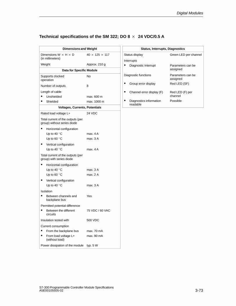
Digital Modules
3-73S7-300 Programmable Controller Module SpecificationsA5E00105505-02
Technical specifications of the SM 322; DO 8 24 VDC/0.5 A
Dimensions and Weight
Dimensions W H D(in millimeters)
40 125 117
Weight Approx. 210 g
Data for Specific Module
Supports clocked operation
No
Number of outputs 8
Length of cable
Unshielded
Shielded
max. 600 m
max. 1000 m
Voltages, Currents, Potentials
Rated load voltage L+ 24 VDC
Total current of the outputs (pergroup) without series diode
Horizontal configuration
Up to 40 C
Up to 60 C
max. 4 A
max. 3 A
Vertical configuration
Up to 40 C max. 4 A
Total current of the outputs (pergroup) with series diode
Horizontal configuration
Up to 40 C
Up to 60 C
max. 3 A
max. 2 A
Vertical configuration
Up to 40 C max. 3 A
Isolation
Between channels andbackplane bus
Yes
Permitted potential difference
Between the differentcircuits
75 VDC / 60 VAC
Insulation tested with 500 VDC
Current consumption
From the backplane bus
From load voltage L+(without load)
max. 70 mA
max. 90 mA
Power dissipation of the module typ. 5 W
Status, Interrupts, Diagnostics
Status display Green LED per channel
Interrupts
Diagnostic Interrupt Parameters can beassigned
Diagnostic functions
Group error display
Channel error display (F)
Diagnostics information readable
Parameters can beassigned
Red LED (SF)
Red LED (F) perchannel
Possible

Digital Modules
3-74S7-300 Programmable Controller Module Specifications
A5E00105505-02
Data for Selecting an Actuator
Output voltage
At signal ”1”
Without series diode
With series diode
min. L + (–0.8 V)
min. L + (–1.6 V)
Output current
At signal ”1”
Rated value
Permitted range
0.5 A
10 mA to 0.6 A1)
At signal ”0” (leakage current)
max. 0.5 mA
Output delay (for resistive load)
At ”0” to ”1”
At ”1” to ”0”
max. 180 s
max. 245 s
Load resistor range 48 to 3 k
Lamp load max. 5 W
Parallel connection of 2 outputs
For redundant actuation of a load
Output with seriesdiode only, must havethe same referencepotential
To increase performance Not possible
Triggering a digital input Possible
1 binary inputaccording to IEC61131, Type 2;
Type 1 with disabledopen-circuit monitoring
Switch rate
For resistive load
Inductive load according toIEC 947-5-1, 13 DC
For lamp load
max. 100 Hz
max. 2 Hz
max. 10 Hz
Limit (internal) of the inductivecircuit interruption voltage up
typ. L + (–45 V)
Short-circuit protection of theoutput
Yes, electronic
Threshold on typ. 0.75 A to 1.5 A
1) 5 mA to 0.6 A with disabled open-circuit monitoring

Digital Modules
3-75S7-300 Programmable Controller Module SpecificationsA5E00105505-02
3.23.1 Assigning Parameters to the SM 322; DO 8 24 VDC/0.5 A
Parameterization
You will find a description of the general procedure for assigning parameters todigital modules in Section 3.3.
Parameters of the SM 322; DO 8 24 VDC/0.5 A
You will find an overview of the parameters that you can set and their defaultsettings for the SM 322; DO 8 24 VDC/0.5 A in the table below.
The default settings apply if you have not performed parameter assignment inSTEP 7.
Table 3-18 Parameters of the SM 322; DO 824 VDC/0.5 A
Parameter Value Range DefaultSettings
ParameterType
Scope
Enable
Diagnostic interrupt Yes/no No Dynamic Module
Behavior on CPU STOP Apply substitute value (EWS)
Hold last value (LWH)
EWS
Diagnostics
Wire-break
No load voltage L+
Short-circuit to M
Short-circuit to L+
Yes/no
Yes/no
Yes/no
Yes/no
No
No
No
No
Static Channel
Apply substitute value ”1” Yes/no No Dynamic Channel

Digital Modules
3-76S7-300 Programmable Controller Module Specifications
A5E00105505-02
3.23.2 Behavior and Diagnostics of the SM 322; DO 8 24 VDC/0.5 A
Effect of operating and mode supply voltage on the output values
The output values of the SM 322; DO 8 24 VDC/0.5 A depend on the operatingmode of the CPU and on the supply voltage of the module.
Table 3-19 Dependence of the Output Values on the Operating Mode of the CPU and onthe Supply Voltage L+ of the SM 322; DO 8 24 VDC/0.5 A.
CPU Operating State Power Supply L+ to DigitalModule
Output Value of DigitalModule
POWER ON RUN L+ exists CPU value
L+ missing 0 signal
STOP L+ exists Substitute value/last value (0 signal preset)
L+ missing 0 signal
POWER – L+ exists 0 signalOFF
L+ missing 0 signal
Behavior upon failure of the supply voltage
Failure of the supply voltage of the SM 322; DO 8 24 VDC/0.5 A is alwaysindicated by the SF LED on the module. Furthermore, this information is madeavailable on the module (entry in diagnosis).
Triggering of the diagnostic interrupt depends on the parameter assignment (seeSection 3.23.3).

Digital Modules
3-77S7-300 Programmable Controller Module SpecificationsA5E00105505-02
Diagnostic messages of the SM 322; DO 8 24 VDC/0.5 A
The following table provides an overview of the diagnostic messages of theSM 322; DO 8 24 VDC/0.5 A.
Table 3-20 Diagnostic Messages of the SM 322; DO 8 24 VDC/0.5 A
Diagnostics Message LED Scope of the Diagno-stics
Parameters canbe Assigned
Wire-break SF Channel Yes
Load voltage missing SF Channel Yes
Short-circuit to M SF Channel Yes
Short-circuit to L+ SF Channel Yes
External auxiliary supply missing SF Module No
Internal auxiliary power missing SF Module No
Fuse blown SF Module No
Watchdog timeout SF Module No
EPROM error SF Module No
RAM error SF Module No
* Open-circuit detection is performed at a current < 1 mA.When suitably parameterized, a wire-break results only in theSF LED and the corresponding channel error LED lighting up.
Note
A prerequisite for detecting the errors indicated by programmable diagnosticmessages is that you have assigned parameters to the digital module accordinglyin STEP 7.

Digital Modules
3-78S7-300 Programmable Controller Module Specifications
A5E00105505-02
Causes of error and remedial action
Table 3-21 Diagnostic Messages of the SM 322; DO 8 24 VDC/0.5 A, Causes of Error and RemedialAction
DiagnosticsMessage
ErrorDetection ...
Possible Error Cause Remedy
Wire-break Only withoutput to ”1”
Open circuit between moduleand actuator
Close circuit
Channel not connected(open)
Disable the ”DiagnoseWire-break” parameter for thechannel in STEP 7
No load voltage Only withoutput to ”1”
Defective output Replace module
Short-circuit to M Only with Overload of output Eliminate overloadoutput to ”1”
Short-circuit of output to M Eliminate short circuit
Short-circuit to L+ Always Short-circuit at output to L+ ofmodule supply
Eliminate short circuit
No external auxiliaryvoltage
Always Power supply L+ to modulemissing
Feed supply L+
No internal auxiliaryvoltage
Always Power supply L+ to modulemissing
Feed supply L+
Fuse in module defective Replace module
Fuse blown Always Fuse in module defective Replace module
Watchdog tripped Always Temporary highelectromagnetic interference
Eliminate interference
Module defective Replace module
EPROM error Always Temporary highelectromagnetic interference
Eliminate interference andswitch on/off power supply ofCPU
Module defective Replace module
RAM error Always Temporary highelectromagnetic interference
Eliminate interference andswitch on/off power supply ofCPU
Module defective Replace module

Digital Modules
3-79S7-300 Programmable Controller Module SpecificationsA5E00105505-02
3.23.3 Interrupts of the SM 322; DO 8 24 VDC/0.5 A
Introduction
The SM 322; DO 8 24 VDC/0.5 A can trigger diagnostic interrupts.
The OBs and SFCs mentioned below can be found in the online Help for STEP 7,where they are described in greater detail.
Enabling interrupts
The interrupts are not preset – in other words, they are inhibited withoutappropriate parameter assignment. Assign parameters to the Interrupt Enable inSTEP 7 (refer to Section 3.23.1).
Diagnostic interrupt
If you have enabled diagnostic interrupts, then active error events (initialoccurrence of the error) and departing error events (message aftertroubleshooting) are reported by means of an interrupt.
The CPU interrupts the execution of the user program and processes thediagnostic interrupt block (OB 82).
In the user program, you can call SFC 51 or SFC 59 in OB 82 to obtain moredetailed diagnostic information from the module.
The diagnostic information is consistent until such time as OB 82 is exited. WhenOB 82 is exited, the diagnostic interrupt is acknowledged on the module.

Digital Modules
3-80S7-300 Programmable Controller Module Specifications
A5E00105505-02
3.24 Digital Output Module SM 322; DO 8 48-125 VDC/1.5 A;(6ES7 322-1CF80-0AA0)
Order number: ”SIMATIC Outdoor module”
6ES7 322-1CF80-0AA0
Characteristics
The SM 322; DO 8 48-125 VDC/1.5 A features the following characteristics:
8 outputs, reverse polarity protection and isolated in groups of 4
1.5 A output current
Rated load voltage 48 to 125 VDC
Suitable for solenoid valves, DC contactors and indicator lights
Group error display
Using the module with high-speed counters
Please take note of the following information on the use of the module inconnection with high-speed counters:
Note
When connecting the power supply via a mechanical contact, the outputs of theSM 322; DO 8 48-125 VDC/1.5 A carry a ”1” signal for approximately 50 s forreasons associated with the circuitry.

Digital Modules
3-81S7-300 Programmable Controller Module SpecificationsA5E00105505-02
Terminal assignment and block diagram of the SM 322; DO 8 48-125 VDC/1.5A
Channel number
Status display – green
1M
48 to 125 V
1 L+
2M
48 to 125 V
2 L+
SF
1
3
5
7
9
10Backplane bus
interface
+ 5 V
+ 5 V 11
13
15
17
19
20
SF
Fault indicator – red
Figure 3-25 Module View and Block Diagram of the SM 322; DO 8 48-125 VDC/1.5 A
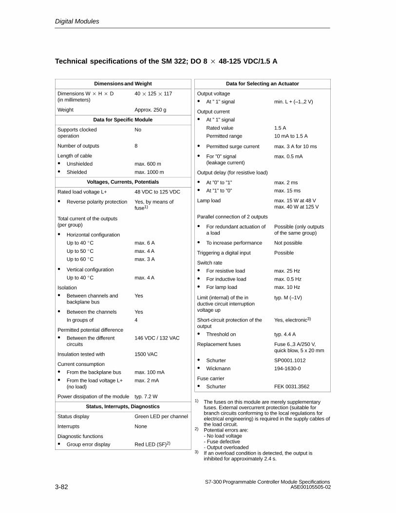
Digital Modules
3-82S7-300 Programmable Controller Module Specifications
A5E00105505-02
Technical specifications of the SM 322; DO 8 48-125 VDC/1.5 A
Dimensions and Weight
Dimensions W H D(in millimeters)
40 125 117
Weight Approx. 250 g
Data for Specific Module
Supports clocked operation
No
Number of outputs 8
Length of cable
Unshielded
Shielded
max. 600 m
max. 1000 m
Voltages, Currents, Potentials
Rated load voltage L+ 48 VDC to 125 VDC
Reverse polarity protection Yes, by means offuse1)
Total current of the outputs(per group)
Horizontal configuration
Up to 40 C
Up to 50 C
Up to 60 C
max. 6 A
max. 4 A
max. 3 A
Vertical configuration
Up to 40 C max. 4 A
Isolation
Between channels andbackplane bus
Yes
Between the channels
In groups of
Yes
4
Permitted potential difference
Between the differentcircuits
146 VDC / 132 VAC
Insulation tested with 1500 VAC
Current consumption
From the backplane bus
From the load voltage L+(no load)
max. 100 mA
max. 2 mA
Power dissipation of the module typ. 7.2 W
Status, Interrupts, Diagnostics
Status display Green LED per channel
Interrupts None
Diagnostic functions
Group error display Red LED (SF)2)
Data for Selecting an Actuator
Output voltage
At ” 1” signal min. L + (–1.,2 V)
Output current
At ” 1” signal
Rated value
Permitted range
1.5 A
10 mA to 1.5 A
Permitted surge current max. 3 A for 10 ms
For ”0” signal (leakage current)
max. 0.5 mA
Output delay (for resistive load)
At ”0” to ”1”
At ”1” to ”0”
max. 2 ms
max. 15 ms
Lamp load max. 15 W at 48 Vmax. 40 W at 125 V
Parallel connection of 2 outputs
For redundant actuation ofa load
Possible (only outputsof the same group)
To increase performance Not possible
Triggering a digital input Possible
Switch rate
For resistive load
For inductive load
For lamp load
max. 25 Hz
max. 0.5 Hz
max. 10 Hz
Limit (internal) of the inductive circuit interruptionvoltage up
typ. M (–1V)
Short-circuit protection of theoutput
Threshold on
Yes, electronic3)
typ. 4.4 A
Replacement fuses Fuse 6.,3 A/250 V,quick blow, 5 x 20 mm
Schurter
Wickmann
SP0001.1012
194-1630-0
Fuse carrier
Schurter FEK 0031.3562
1) The fuses on this module are merely supplementaryfuses. External overcurrent protection (suitable forbranch circuits conforming to the local regulations forelectrical engineering) is required in the supply cables ofthe load circuit.
2) Potential errors are:- No load voltage- Fuse defective- Output overloaded
3) If an overload condition is detected, the output isinhibited for approximately 2.4 s.

Digital Modules
3-83S7-300 Programmable Controller Module SpecificationsA5E00105505-02
3.25 Digital Output Module SM 322;DO 8 120/230 VAC/2 A; (6ES7 322-1FFx1-0AA0)
Order number: ”Standard module”
6ES7 322-1FF01-0AA0
Order number: ”SIMATIC Outdoor module”
6ES7 322-1FF81-0AA0
Characteristics
The SM 322; DO 8 120/230 VAC/2 A features the following characteristics:
8 outputs, fused and isolated in groups of 4
2 A output current
120/230 VAC rated load voltage
Suitable for AC solenoid valves, contactors, motor starters, fractional h.p.motors and indicator lights.
Group error display

Digital Modules
3-84S7-300 Programmable Controller Module Specifications
A5E00105505-02
Terminal assignment and block diagram of the SM 322; DO 8 120/230 VAC/2 A
Backplane businterface
2L
1L
M
M
2N
1N
Channel number
Status display – green
SF
* Zero cross inhibit voltage triacFault indicator – red
*
*
5 V
M
M
SF
5 V
Figure 3-26 Module View and Block Diagram of the SM 322; DO 8 120/230 VAC/2 A

Digital Modules
3-85S7-300 Programmable Controller Module SpecificationsA5E00105505-02
Technical specifications of the SM 322; DO 8 120/230 VAC/2 A
Dimensions and Weight
Dimensions W H D(in millimeters)
40 125 117
Weight Approx. 275 g
Data for Specific Module
Supports clocked operation
No
Number of outputs 8
Length of cable
Unshielded
Shielded
max. 600 m
max. 1000 m
Voltages, Currents, Potentials
Rated load voltage L1
Permitted frequency range
120/230 VAC
47 Hz to 63 Hz
Total current of the outputs(per group)
Horizontal configuration
Up to 40 C max. 4 A
Up to 60 C max. 2 A
Vertical configuration
Up to 40 C max. 2 A
Isolation
Between channels andbackplane bus
Between the channels
In groups of
Yes
Yes
4
Permitted potential difference
Between Minternal and theoutputs
230 VAC
Between the outputs of thedifferent groups
500 VAC
Insulation tested with 1500 VAC
Current consumption
From the backplane bus
From load voltage L1(without load)
max. 100 mA
max. 2 mA
Power dissipation of the module typ. 8.6 W
Status, Interrupts, Diagnostics
Status display Green LED per channel
Interrupts None
Diagnostic functions
Group error display
Yes
Red LED (SF) 2)
Data for Selecting an Actuator
Output voltage
At signal ”1”
– At maximum current
– At minimum current
min. L1 (–1.5 V)
min. L1 (–8.5 V)
Output current
At signal ”1”
Rated value AC 2 A1)
Permitted range for 0 C to40 C
10 mA to 2 A
Permitted range for 40 Cto 60 C
10 mA to 1 A
Permitted current surge(per group)
max. 20 A(not more than 1 ACscan cycle)
At signal ”0” (leakage current)
max. 2 mA
Output delay (for resistive load)
From ”0” to ”1” Not more than 1 ACscan cycle
From ”1” to ”0” Not more than 1 ACscan cycle
Minimum load current 10 mA
Zero cross inhibit voltage max. 60 V
Size of the motor starter max. size 5 to NEMA
Lamp load max. 50 W
Connecting two outputs in parallel
For redundant triggering ofa load
Possible (only outputsof the same group)
To increase performance Not possible
Triggering a digital input Possible
Switch rate
For resistive load
Inductive loads, accordingto IEC 947-5-1, AC 15
For lamp load
max. 10 Hz
max. 0.5 Hz
1 Hz
Short-circuit protection of output
Fuse, 8 A/250 V; pergroup
Min. current required forfuse to blow
min. 40 A
Max. response time max. 300 ms

Digital Modules
3-86S7-300 Programmable Controller Module Specifications
A5E00105505-02
Replacement fuses
Wickmann
Schurter
Littelfuse
8 A fuse/quick-acting
194-1800-0
SP001.1013
217.008
Fuse carrier
Wickmann 653 07
1) The load current must not be half-wave2) Potential errors are:
- No load voltage- Fuse defective
3.26 Digital Output Module SM 322; DO 8 120/230 VAC/2 A ISOL (6ES7 322-5FF00-0AB0)
Order number
6ES7 322-5FF00-0AB0
Characteristics
Digital output module SM 322; DO 8 × 120/230 VAC/2 A ISOL has the followingdistinguishing characteristics:
8 outputs, isolated in one group
Group error display
Channel-specific status LEDs
Programmable diagnostics
Programmable diagnostic interrupt
Programmable substitute value output
2 A output current
120/230 VAC rated load voltage
Suitable for AC solenoid valves, contactors, motor starters, fractional h.p.motors and indicator lights.

Digital Modules
3-87S7-300 Programmable Controller Module SpecificationsA5E00105505-02
Terminal assignment and block diagram of the SM 322; DO 8 120/230 VAC/2 A ISOL
Status display – green
Backplane businterface
1
M
4
Group error display – red
1L
2L
1011
20
7
1417
L5
30
40
34
21
2427
31
37
Channelnumber
SF
3L
4L
L6
7L
8L
M
Figure 3-27 Module View and Block Diagram of the SM 322; DO 8 x 120/230 VAC/2 A ISOL

Digital Modules
3-88S7-300 Programmable Controller Module Specifications
A5E00105505-02
Technical specifications of the SM 322; DO 8 120/230 VAC/2 A ISOL
Dimensions and Weight
Dimensions W × H × D(in millimeters)
40 × 125 × 117
Weight Approx. 275 g
Data for Specific Module
Supports clocked operation
No
Number of outputs 8
Length of cable
Unshielded
Shielded
max. 600 m
max. 1000 m
Voltages, Currents, Potentials
Rated load voltage L1 120/230 VAC
Total current of the outputs(module)
Horizontal configuration
Up to 40 °CUp to 60 °C
max. 8 A
max. 4 A
Vertical configuration
Up to 40 °Cmax. 4 A
Isolation
Between channels andbackplane bus
Yes
Between channels
In groups of
Yes
1
Permitted potential difference
Between Minternal and theoutputs
230 VAC
Between outputs 500 VAC
Insulation tested with
Between Minternal and theoutputs
1500 VAC
Between the outputs of thedifferent groups
2000 VAC
Current consumption
From the backplane bus
From load voltage L1(without load)
max. 100 mA
max. 2 mA
Power dissipation of the module typ. 8.6 W
Status, Interrupts, Diagnostics
Status display Green LED per channel
Interrupts
Diagnostic Interrupt Parameters can beassigned
Diagnostic functions
Group error display Red LED (SF)
Data for Selecting an Actuator
Output voltage
At signal ”1” min. L1 (-8.5 V)
Output current
At signal ”1”
Rated value
Permitted range for 0 °C to40 °C
2 A
10 mA to 2 A
Permitted range for40 °C to 60 °C
10 mA to 1 A
Permitted surge current (per group)
max. 20 A(with 2 half-waves)
For ”0” signal (leakage current)
max. 2 mA
Zero cross inhibit voltage max. 60 V
Size of the motor starter max. size 5 to NEMA
Lamp load max. 50 W
Connecting two outputs in parallel
For redundant triggering ofa load
Possible
To increase performance Not possible
Triggering a digital input Possible
Switch rate
For resistive load max. 10 Hz
Inductive loads, accordingto IEC 947-5-1, AC 15
max. 0.5 Hz
For lamp load max. 1 Hz
Short-circuit protection of output Yes, 3.15 A / 250 V fuse, fast-acting

Digital Modules
3-89S7-300 Programmable Controller Module SpecificationsA5E00105505-02
Note
The outputs must be protected by a high-speed, fast-acting 3.15 A 250 VAC fuse.When mounted in a hazardous area in accordance with the National Electric Code,a tool must be used to remove the fuse and the area must be designated safebefore the fuse is removed/replaced.
Parameterization of the SM 322; DO x 120/230 VAC/2 A ISOL
A description of the general procedure for parameterizing digital modules can befound in section 3.3.
Detailed information on the digital output module parameters can be found inAppendix A.3.
Parameters of the SM 322; DO 8 x 120/230 VAC/2 A ISOL
Table 3-22 shows the settable parameters with the default settings for the SM 322;DO 8 x 120/230 VAC/2 A ISOL.
The default settings apply if you have not performed parameter assignment inSTEP 7.
Table 3-22 Parameters of the SM 322; DO 8 x 120/230 VAC/2 A ISOL
Parameter Value Range Defaultsettings
Parametertype
Scope
Enable
Diagnostic interrupts Yes/no No Dynamic Module
Behavior on CPU STOP Switch substitute value(EWS)
Hold last value (LWH)
EWS Dynamic Channel
Switch substitute value”1”
Yes/no No Dynamic Channel

Digital Modules
3-90S7-300 Programmable Controller Module Specifications
A5E00105505-02
Behavior and Diagnostics of the SM 322; DO 8 x 120/230 VAC/2 A ISOL
Table 3-23 gives an overview of the diagnostic messages of theSM 322; DO 8 x 120/230 VAC/2 A ISOL.
Table 3-23 Diagnostic Messages of the SM 322; DO 8 x 120/230 VAC/2 A ISOL
Diagnostics Message LED Scope of the Diagnostics ParaAeters can beassigned
Time-out SF Module No
EPROM error SF Module No
RAM error SF Module No
Error causes and remedies
Table 3-24 shows the diagnostic messages and error causes as well as theremedies of the SM 322; DO 8 x 120/230 VAC/2 A ISOL.
Table 3-24 Diagnostic Messages of the SM 322; DO 8 x 120/230 VAC/2 A ISOL, ErrorCauses and Remedies
DiagnosticsMessage
Error Detection Possible Error Cause Remedy
Time-out Always Transient highelectromagneticinterference
Remove interference and turnthe CPU power supply off andon
Module defective Replace module
EPROM error Always Transient highelectromagneticinterference
Remove interference and turnthe CPU power supply off andon
Module defective Replace module
RAM error Always Transient highelectromagneticinterference
Remove interference and turnthe CPU power supply off andon
Module defective Replace module

Digital Modules
3-91S7-300 Programmable Controller Module SpecificationsA5E00105505-02
Interrupts of the SM 322; DO 8 x 120/230 VAC/2 A ISOL
The SM 322; DO 8 x 120/230 VAC/2 A ISOL can trigger diagnostic interrupts.
The OBs and SFCs mentioned below are described in detail in the online Help forSTEP 7.
Enabling interrupts
The interrupts are not available – in other words, they are withheld withoutappropriate parameter assignment. Use STEP 7 to assign parameters for enablinginterrupts.
Diagnostic interrupt
If you have enabled diagnostic interrupts, then active error events (initialoccurrence of the error) and departing error events (message aftertroubleshooting) are reported by means of interrupts.
The CPU interrupts execution of the user program and processes the diagnosticinterrupt block (OB 82).
In the user program, you can call SFC 51 or SFC 59 in OB 82 to obtain moredetailed diagnostic information from the module.
The diagnostic information is consistent until such time as OB 82 is exited. WhenOB 82 is exited, the diagnostic interrupt is acknowledged at the module.
Load restrictions with a horizontal configuration
With a horizontal configuration, the module loads must be restricted so that twoadjacent inputs or outputs do not exceed the maximum rating for an input or anoutput.
Load restrictions with a vertical configuration
With a vertical configuration, the module loads must be restricted so that fouradjacent inputs or outputs do not exceed the maximum rating for an input or anoutput.

Digital Modules
3-92S7-300 Programmable Controller Module Specifications
A5E00105505-02
3.27 Relay Output Module SM 322; DO 16 Rel. 120/230 VAC;(6ES7 322-1HH01-0AA0)
Order number
6ES7 322-1HH01-0AA0
Characteristics
The SM 322; DO 16 Rel. 120/230 VAC features the following characteristics:
16 outputs, isolated in groups of 8
Rated load voltage 24 VDC to 120 VDC, 48 VAC to 230 VAC
Suitable for AC/DC solenoid valves, contactors, motor starters, fractional h.p.motors and indicator lights.
Behavior upon power down of the supply voltage
Note
When the power supply is switched off, the capacitor still stores energy forabout 200 ms. The relay can therefore still be driven briefly within this time by theuser program.

Digital Modules
3-93S7-300 Programmable Controller Module SpecificationsA5E00105505-02
Terminal assignment and block diagram of the SM 322; DO 16 Rel. 120/230 VAC
Channel number
Status display – green
L +N
M
M
Backplane businterface
NM
24 V
Figure 3-28 Module View and Block Diagram of SM 322; DO 16 Rel. 120/230 VAC

Digital Modules
3-94S7-300 Programmable Controller Module Specifications
A5E00105505-02
Technical specifications of the SM 322; DO 16 Rel. 120/230 VAC
Dimensions and Weight
Dimensions W H D(in millimeters)
40 125 117
Weight Approx. 250 g
Data for Specific Module
Supports clocked operation
No
Number of outputs 16
Length of cable
Unshielded
Shielded
max. 600 m
max. 1000 m
Voltages, Currents, Potentials
Rated supply voltage of therelay L +
24 VDC
Total current of the outputs (per group)
max. 8 A
Isolation
Between channels andbackplane bus
Yes
Between the channels
In groups of
Yes
8
Permitted potential difference
Between Minternal andsupply voltage of the relays
75 VDC / 60 VAC
Between Minternal andsupply voltage of the relaysand the outputs
230 VAC
Between the outputs of thedifferent groups
500 VAC
Insulation tested with
Between Minternal andsupply voltage of the relays
500 VDC
Between Minternal andsupply voltage of the relaysand the outputs
1500 VAC
Between the outputs of thedifferent groups
2000 VAC
Current consumption
From the backplane bus
From supply voltage L+
max. 100 mA
max. 250 mA
Power dissipation of the module typ. 4.5 W
Status, Interrupts, Diagnostics
Status display Green LED per channel
Interrupts None
Diagnostic functions None
Data for Selecting an Actuator
Continuous thermal current max. 2 A
Minimum load voltage / current 10 V / 10 mA
Short-circuit proof toIEC 947-5-1
200 A, with B10/B16circuit breaker
Switching capacity and lifetime of the contacts
For resistive load
Voltage Cur-rent
No. of switch-ing cyc. (typ.)
24 VDC
60 VDC120 VDC24 VAC48 VAC60 VAC120 VAC
230 VAC
2.0 A1.0 A0.5 A0.5 A0.2 A1.5 A1.5 A1.5 A2.0 A1.0 A0.5 A2.0 A1.0 A0.5 A
0.1 million0.2 million1.0 million0.2 million0.6 million1.5 million1.5 million1.5 million1.0 million1.5 million2.0 million1.0 million1.5 million2.0 million
Inductive load according to IEC 947-5-1 DC13/AC15
Voltage Cur-rent
No. of switch-ing cyc. (typ.)
24 VDC
60 VDC120 VDC24 VAC48 VAC60 VAC120 VAC
230 VAC
2.0 A1.0 A0.5 A0.5 A0.2 A1.5 A1.5 A1.5 A2.0 A1.0 A0.5 A2.0 A1.0 A0.5 A
0.05 million0.1 million0.5 million0.1 million0.3 million1 million1 million1 million0.7 million1.0 million1.5 million0.7 million1.0 million1.5 million
An external protection circuit will enhance the service lifeof the contacts.

Digital Modules
3-95S7-300 Programmable Controller Module SpecificationsA5E00105505-02
Size of the motor starter max. size 5 to NEMA
Lamp load 50 W / 230 VAC5 W / 24 VDC
Contact protection (internal) None
Parallel connection of 2 outputs
For redundant triggering ofa load
Possible (only outputsof the same group)
To increase performance Not possible
Triggering a digital input Possible
Switch rate
Mechanical max. 10 Hz
For resistive load 1 Hz
Inductive loads accordingto IEC 947-5-1, DC 13/AC 15
max. 0.5 Hz
For lamp load 1 Hz
3.28 Relay Output Module SM 322; DO 8 Rel. 230 VAC;(6ES7 322-1HF01-0AA0)
Order number
6ES7 322-1HF01-0AA0
Characteristics
The SM 322; DO 8 REL. 230 VAC features the following characteristics:
8 outputs, isolated in groups of 2
Rated load voltage 24 VDC to 120 VDC, 48 VAC to 230 VAC
Suitable for AC/DC solenoid valves, contactors, motor starters, fractional h.p.motors and indicator lights.
Behavior upon power down of the supply voltage
Note
Applicable only for the SM 322; DO 8 Rel. 230 VAC with product status 1 is:
When the power supply is switched off, the capacitor still stores energy for about200 ms. The relay can therefore still be driven briefly within this time by the userprogram.

Digital Modules
3-96S7-300 Programmable Controller Module Specifications
A5E00105505-02
Terminal assignment and block diagram of the SM 322; DO 8 Rel. 230 VAC
Status display – green
Channel number
U
M
Backplane businterface
M
U
24 V
M
Figure 3-29 Module View and Block Diagram of the SM 322; DO 8 REL. 230 VAC

Digital Modules
3-97S7-300 Programmable Controller Module SpecificationsA5E00105505-02
Technical specifications of the SM 322; DO 8 Rel. 230 VAC
Dimensions and Weight
Dimensions W H D(in millimeters)
40 125 117
Weight Approx. 190 g
Data for Specific Module
Supports clocked operation
No
Number of outputs 8
Length of cable
Unshielded
Shielded
max. 600 m
max. 1000 m
Voltages, Currents, Potentials
Rated supply voltage of therelay L +
24 VDC
Total current of the outputs (per group)
max. 4 A
Isolation
Between channels andbackplane bus
Yes
Between the channels
In groups of
Yes
2
Permitted potential difference
Between Minternal andsupply voltage of the relays
75 VDC / 60 VAC
Between Minternal andsupply voltage of the relaysand the outputs
230 VAC
Between the outputs of thedifferent groups
400 VAC
Insulation tested with
Between Minternal andsupply voltage of the relays
500 VDC
Between Minternal andsupply voltage of the relaysand the outputs
1500 VAC
Between the outputs of thedifferent groups
1500 VAC
Current consumption
From the backplane bus
From supply voltage L+
max. 40 mA
max. 160 mA
Power dissipation of the module typ. 3.2 W
Status, Interrupts, Diagnostics
Status display Green LED per channel
Interrupts None
Diagnostic functions None
Data for Selecting an Actuator
Continuous thermal current max. 3 A
Minimum load voltage / current 10 V /5 mA
Short-circuit proof according toIEC 947-5-1 2)
With circuit-breaker ofcharacteristic B for:
cos 1.0: 600 A
cos 0.5 to 0.7: 900 A
With Diazed 8 A fuse:1000 A
Switching capacity and lifetime of the contacts
For resistive load
Voltage Current No. ofswitchingcyc. (typ.)
24 VDC
60 VDC120 VDC48 VAC60 VAC120 VAC
230 VAC
2.0 A1.0 A0.5 A0.5 A0.2 A2.0 A2.0 A2.0 A1.0 A0.5 A2.0 A1.0 A0.5 A
0.7 million1.6 million4 million1.6 million1.6 million1.6 million1.2 million0.5 million 2)
0.7 million 2)
1.5 million 2)
0.5 million 2)
0.7 million 2)
1.5 million
Inductive load according to IEC 947-5-1 13 DC/15 AC
Voltage Current No. ofswitchingcyc. (typ.)
24 VDC
60 VDC120 VDC48 VAC60 VAC120 VAC
230 VAC
2.0 A1.0 A0.5 A0.5 A0.2 A1.5 A1.5 A2.0 A1.0 A0.7 A0.5 A2.0 A1.0 A0.5 A
0.3 million0.5 million1.0 million0.5 million0.3 million 2)
1 million1 million0.2 million0.7 million1 million2.0 million0.3 million 2)
0.7 million 2)
2 million 2)
Contact protection (internal) Varistor SIOV-CU4032K275 G
An external protection circuit will enhance the service lifeof the contacts.

Digital Modules
3-98S7-300 Programmable Controller Module Specifications
A5E00105505-02
Data for Selecting an Actuator, continued
Lamp load 1) max. 50 W
Power No. ofswitchingcyc. (typ.)
Lamp load (230 VAC) 2) 1000 W1500 W
2500010000
Energy-savinglamps/fluorescent lamps withelectronic ballast2)
1058W 25000
Fluorescent lamps,conventionally compensated 2)
158W 25000
Fluorescent lamps,non-compensated 2)
1058W 25000
Connecting two outputs in parallel
For redundant triggering ofa load
Possible (only outputsof the same group)
To increase performance Not possible
Triggering a digital input Possible
Switch rate
Mechanical max. 10 Hz
For resistive load max. 2 Hz
Inductive loads accordingto IEC 947-5-1, DC 13/15AC
max. 0.5 Hz
For lamp load max. 2 Hz
1) Product status 12) Product status 2 or later
3.29 Relay Output Module SM 322; DO 8Rel. 230 VAC/5A; (6ES7 322-5HF00-0AB0)
Order number
6ES7 322-5HF00-0AB0
Characteristics
Relay output module SM 322; DO 8Rel. 230 VAC/5A has the followingdistinguishing characteristics:
8 outputs, isolated in groups of 1
Load voltage 24 VDC to 120 VDC, 24 VAC to 230 VAC
Suitable for AC solenoid valves, contactors, motor starters, fractional h.p.motors and indicator lights.
An RC quenching element can be connected via a jumper (SJ) to protect thecontacts.
Group error display
Channel-specific status LEDs
Programmable diagnostic interrupt
Programmable substitute value output

Digital Modules
3-99S7-300 Programmable Controller Module SpecificationsA5E00105505-02
Protection of contacts against overvoltages
You protect the contacts against overvoltages by inserting jumpers (SJ) on themodule between terminals 3 and 4, 7 and 8, 12 and 13 etc. (refer to Figure 3-30).
Terminal assignment and block diagram of the SM 322; DO 8 x Rel. 230 VAC/5A
Channelnumber
Status display – green
24V
1L+
1L+
1M
Bac
kpla
ne b
us in
terf
ace
2L+
2M
SF
SF
11
12
13
14
15
16
17
18
19
20
Fault indicator – red
1M
SJ
1L+
1M
SJ
1L+
1M
SJ
1L+
1M
SJ
SJ
SJ
1L+
1M1L+
1M
1L+
1M1L+
1M
SJ
SJ
24V
31
32
33
34
35
36
37
38
39
40
21
22
23
24
25
26
27
28
29
30
1
2
3
4
5
6
7
8
9
10
Figure 3-30 Module View and Block Diagram of the SM 322; DO 8 x Rel. 230 VAC/5A

Digital Modules
3-100S7-300 Programmable Controller Module Specifications
A5E00105505-02
Operation with safe electrical extra-low voltage
When using relay output module 6ES7 322-5HF00-0AB0 with safe and electricallyisolated extra-low voltage, take the following special characteristic into account:
If a terminal is operated with a safe and electrically isolated extra-low voltage, thehorizontally adjacent terminal must be operated at a rated voltage of not morethan 120 VUC. With operation at voltages greater than 120 VUC, the creepagesand clearances of the 40-pin front connector do not meet the SIMATICrequirements for safe electrical isolation.
If one of the two horizontally adjacent termi-nals is operated with a safe electrical extra-low voltage, the adjacent terminal must beoperated at not more than UC 120 V.
Figure 3-31 Special Characteristic for Operation with a Safe Electrical Extra-Low Voltage
Technical specifications of the SM 322; DO 8Rel. 230 VAC/5 A
Dimensions and Weight
Dimensions W H D(in millimeters)
40 125 117
Weight Approx. 320 g
Data for Specific Module
Supports clocked operation
No
Number of outputs 8
Length of cable
Unshielded
Shielded
max. 600 m
max. 1000 m
Voltages, Currents, Potentials
Rated supply voltage of theelectronics L +
24 VDC
Reverse polarity protection Yes
Total current of the outputs (per group)
Horizontal configurationUp to 60° C
max. 5 A
Vertical configurationUp to 40 ° C
max. 5 A
Isolation
Between channels andbackplane bus
Yes
Between the channels andthe relay supply voltage
Yes
Between the channels
In groups of
Yes
1
Permitted potential difference
Between Minternal andsupply voltage of the relays
75 VDC / 60 VAC
Between Minternal andsupply voltage of the relaysand the outputs
250 VAC
Between the outputs of thedifferent groups
500 VAC

Digital Modules
3-101S7-300 Programmable Controller Module SpecificationsA5E00105505-02
Insulation tested with
Between Minternal andsupply voltage of the relays
500 VDC
Between Minternal andsupply voltage of the relaysand the outputs
1500 VAC
Between the outputs of thedifferent groups
2000 VAC
Current consumption
From the backplane bus
From supply voltage L+
max. 100 mA
max. 160 mA
Power dissipation of the module typ. 3.5 W
Status, Interrupts, Diagnostics
Status display Green LED per channel
Interrupts
Diagnostic Interrupt Parameters can beassigned
Diagnostic functions Parameters can beassigned
Group error display Red LED (SF)
Diagnostics informationread-out
Possible
Data for Selecting an Actuator
Continuous thermal current max. 5 A
Minimum load voltage / current 10 V /10 mA1)
Leakage current 11.5 mA 2)
Short-circuit proof according to IEC 947-5-1
With circuit-breaker ofcharacteristic B for:
cos 1.0: 600 A
cos 0.5 to 0.7: 900 A
With Diazed 8 A fuse:1000 A
Switching capacity and lifetime of the contacts
For resistive load
Voltage Current No. ofswitchingcyc. (typ.)
24 VDC24 VDC24 VDC230 VAC230 VAC230 VAC
5.0 A2.5 A1.0 A5.0 A2.5 A1.0 A
0.2 million0.4 million0.9 million0.2 million0.4 million0.9 million
Inductive load according to IEC 947-5-1 13 DC/15 AC
Voltage Current No. ofswitchingcyc. (typ.)
24 VDC24 VDC24 VDC230 VAC230 VAC230 VAC
5.0 A2.5 A1.0 A5.0 A2.5 A1.0 A
0.1 million0.25 million0.5 million0.1 million0.25 million0.5 million
With a connected RC quenching element (jumper ”SJ”inserted) or with an external protection circuit, youlengthen the service life of the contacts.
Size of the motor starter max. size 5 to NEMA
Power No. ofswitchingcyc. (typ.)
Lamp load (230 VAC) 1000 W1500 W
2500010000
Energy-savinglamps/fluorescent lamps withelectronic ballast
1058W 25000
Fluorescent lamps,conventionally compensated
158W 25000
Fluorescent lamps,non-compensated
1058W 25000
Contact protection RC quenching element 330 Ω, 0.1 F
Connecting two outputs in parallel
For redundant triggering ofa load
Possible (only outputswith identical load vol-tage)
To increase performance Not possible
Triggering a digital input Possible
Switch rate
Mechanical max. 10 Hz
For resistive load max. 2 Hz
Inductive loads accordingto IEC 947-5-1, DC 13/15AC
max. 0.5 Hz
For lamp load max. 2 Hz
1) Without inserted jumper (SJ).2) For AC load voltage and inserted jumper (SJ). Without
jumper (SJ) inserted there is a leakage current

Digital Modules
3-102S7-300 Programmable Controller Module Specifications
A5E00105505-02
Note
Due to the leakage current of the RC quenching element, wrong signal statesmight occur when an IEC Type 1 input is connected (remove SJ jumper)
3.29.1 SM 322; DO 8 Rel. 230 VAC/5A parameterization
Parameterization
You will find the general procedure for assigning parameters to digital modules inSection 3.3.
Parameters of the SM 322; DO 8Rel. 230 VAC/5A
You will find an overview of the parameters that you can set and their defaultsettings for the SM 322; DO 8230 VDC/0.5 A in the table below.
Table 3-25 Parameters of the SM 322; DO 8Rel. 230 VAC/5A
Parameter Value Range Defaultsettings
Parametertype
Scope
Enable
Diagnostic Interrupts Yes/no No Dynamic Module
Behavior on CPU STOP Switch substitute value(EWS)
Hold last value (LWH)
EWS Dynamic Channel
Switch substitute value”1”
Yes/no No Dynamic Channel

Digital Modules
3-103S7-300 Programmable Controller Module SpecificationsA5E00105505-02
3.29.2 Behavior and Diagnostics of the SM 322; DO 8 230 VDC/0.5 A
Diagnostic messages of the SM 322; DO 8Rel. 230 VAC/5A
The table below presents an overview of the diagnostic messages for theSM 322; DO 8Rel. 230 VAC/5 A.
Table 3-26 Diagnostic Messages of the SM 322; DO 8Rel. AC 230 VDC/0.5 A
Diagnostics Message LED Scope of the Diagnostics Parameters can beAssigned
Time-out SF Module No
EPROM error SF Module No
RAM error SF Module No

Digital Modules
3-104S7-300 Programmable Controller Module Specifications
A5E00105505-02
Error causes and remedies
Table 3-27 Diagnostic Messages of the SM 322; DO 8Rel. 230 VAC/5A, Error Causes and Remedies
DiagnosticsMessage
Error Detection Possible Error Cause Remedy
Time-out Always Temporary highelectromagneticinterference
Remove interference andturn the CPU power supplyoff and on
Module defective Replace module
EPROM error Always Temporary highelectromagneticinterference
Remove interference andturn the CPU power supplyoff and on
Module defective Replace module
RAM error Always Temporary highelectromagneticinterference
Remove interference andturn the CPU power supplyoff and on
Module defective Replace module
Interrupts of the SM 322; DO 8Rel. 230 VAC/5A
Introduction
The SM 322; DO8Rel. 230 VAC/0.5 A can trigger diagnostic interrupts.
The OBs and SFCs mentioned below can be found in the online Help for STEP 7,where they are described in greater detail.
Enabling interrupts
The interrupts are not available – in other words, they are inhibited withoutappropriate parameter assignment. Use STEP 7 to assign parameters for enablinginterrupts.

Digital Modules
3-105S7-300 Programmable Controller Module SpecificationsA5E00105505-02
Diagnostic Interrupt
If you have enabled diagnostic interrupts, then incoming active error events (initialoccurrence of the error) and departing error events (message aftertroubleshooting) are reported by means of interrupts.
The CPU interrupts execution of the user program and processes the diagnosticinterrupt block (OB 82).
In the user program, you can call SFC 51 or SFC 59 in OB 82 to obtain moredetailed diagnostic information from the module.
The diagnostic information is consistent until such time as OB 82 is exited. WhenOB 82 is exited, the diagnostic interrupt is acknowledged on the module.
3.30 Relay Output Module SM 322; DO 8 Rel. 230 VAC/5 A;(6ES7 322-1HFx0-0AA0)
Order number: ”Standard module”
6ES7 322-1HF10-0AA0
Order number: ”SIMATIC Outdoor module”
6ES7 322-1HF80-0AA0
Characteristics
The SM 322; DO 8Rel. 230 VAC/5 A features the following characteristics:
8 outputs, isolated in groups of 1
Rated load voltage 24 VDC to 120 VDC, 48 VAC to 230 VAC
Suitable for AC/DC solenoid valves, contactors, motor starters, fractional h.p.motors and indicator lights.
Measures with switching currents > 3 A
Note
To keep the additional temperature rise of the module near the connectors as lowas possible, you must select a cable cross-section of 1.5 mm2 for connectingcables with switching currents > 3 A.

Digital Modules
3-106S7-300 Programmable Controller Module Specifications
A5E00105505-02
Terminal assignment and block diagram of the SM 322; DO 8 Rel. 230 VAC/5 A
Channelnumber
Status display -green
L+
24 V
M
L+
M
L+
M
L+
M M
L+M
L+
M
L+
M
L+
L+
M
M
Bac
kpla
ne b
us in
terf
ace
L+
1)
Connection possibility for contact supplyI aggregate current 8 A for Ta 30 CI aggregate current 5A for Ta 60 C
1)
1)
1)
Figure 3-32 Module View and Block Diagram of the SM 322; DO 8 Rel. 230 VAC/5 A
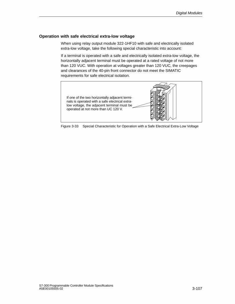
Digital Modules
3-107S7-300 Programmable Controller Module SpecificationsA5E00105505-02
Operation with safe electrical extra-low voltage
When using relay output module 322-1HF10 with safe and electrically isolatedextra-low voltage, take the following special characteristic into account:
If a terminal is operated with a safe and electrically isolated extra-low voltage, thehorizontally adjacent terminal must be operated at a rated voltage of not morethan 120 VUC. With operation at voltages greater than 120 VUC, the creepagesand clearances of the 40-pin front connector do not meet the SIMATICrequirements for safe electrical isolation.
If one of the two horizontally adjacent termi-nals is operated with a safe electrical extra-low voltage, the adjacent terminal must beoperated at not more than UC 120 V.
Figure 3-33 Special Characteristic for Operation with a Safe Electrical Extra-Low Voltage

Digital Modules
3-108S7-300 Programmable Controller Module Specifications
A5E00105505-02
Technical specifications of the SM 322; DO 8 Rel. 230 VAC/5 A
Dimensions and Weight
Dimensions W H D(in millimeters)
40 125 120
Weight Approx. 320 g
Data for Specific Module
Supports clocked operation
No
Number of outputs 8
Length of cable
Unshielded
Shielded
max. 600 m
max. 1000 m
Voltages, Currents, Potentials
Rated supply voltage of therelay L +
24 VDC
Total current of the outputs (per group)
Horizontal configuration
Up to 30 C
Up to 60 C
Vertical configuration
Up to 40 C
max. 8 A
max. 5 A
max. 5 A
Isolation
Between channels andbackplane bus
Yes
Between the channels
In groups of
Yes
1
Permitted potential difference
Between Minternal andsupply voltage of therelays
75 VDC / 60 VAC
Between Minternal andsupply voltage of therelays and the outputs
250 VAC
Between the outputs of thedifferent groups
500 VAC
Insulation tested with
Between Minternal andsupply voltage of therelays
500 VDC
Between Minternal andsupply voltage of therelays and the outputs
1500 VAC
Between the outputs of thedifferent groups
2000 VAC
Current consumption
From the backplane bus
From supply voltage L+
max. 40 mA
max. 125 mA
Power dissipation of themodule
typ. 4.2 W

Digital Modules
3-109S7-300 Programmable Controller Module SpecificationsA5E00105505-02
Status, Interrupts, Diagnostics
Status display
Interrupt
Diagnostic functions
Green LED per channel
None
None
Data for Selecting an Actuator
Continuous thermal current max. 8 A
Minimum load voltage / current 10 V / 5 mA
Short-circuit proof to IEC 947-5-1
With circuit-breaker ofcharacteristic B for:
cos 1.0: 600 A
cos 0.5 to 0.7: 900 A
With Diazed 8 A fuse:1000 A
Switching capacity and lifetime of the contacts
For resistive load
Voltage Current No. ofswitchingcyc. (typ.)
24 VDC 8.0 A4.0 A2.0 A0.5 A
0.1 million0.3 million0.7 4.0 million
60 VDC 0.5 A 4 million
120 VDC 0.2 A 1.6 mill.
48 VAC 8.0 A2.0 A
0.1 million1.6 million
60 VAC 8.0 A2.0 A
0.1 million1.2 million
120 VAC 8.0 A4.0 A2.0 A1.0 A0.5 A
0.1 million0.3 million0.5 million0.7 million1.5 million
230 VAC 8.0 A4.0 A2.0 A1.0 A0.5 A
0.1 million0.3 million0.5 million0.7 million1.5 million
Switching capacity and lifetime of the contacts
Inductive load according to IEC 947-5-1 13 DC/15 AC
Voltage Current No. ofswitchingcyc. (typ.)
24 VDC 2.0 A1.0 A0.5 A
0.3 million0.5 million1 million
60 VDC 0.5 A0.3 A
0.5 million1 million
120 VDC 0.2 A 0.5 mill.
48 VAC 3.0 A1.5 A
0.5 million1 million
60 VAC 3.0 A1.5 A
0.3 million1 million
120 VAC 3.0 A2.0 A1.0 A0.5 A
0.2 million0.3 million0.7 million2.0 million
230 VAC 3.0 A2.0 A1.0 A0.5 A
0.1 million0.3 million0.7 million2.0 million
Aux. contactors Size 0(3TH28)
30 mill.
An external protection circuit will enhance the service lifeof the contacts.
Power No. ofswitchingcyc. (typ.)
Lamp load (230 VAC) 1000W1500W
2500010000
Energy-savinglamps/fluorescent lamps withelectronic ballast
1058W 25000
Fluorescent lamps,conventionally compensated
158W 25000
Fluorescent lamps,non-compensated
1058W 25000
Contact protection (internal) None
Connecting two outputs in parallel
For redundant actuation ofa load
Possible
To increase performance Not possible
Triggering a digital input Possible
Switch rate
Mechanical max. 10 Hz
For resistive load max. 2 Hz
Inductive loads accordingto IEC 947-5-1, DC 13/15AC
max. 0.5 Hz
For lamp load max. 2 Hz

Digital Modules
3-110S7-300 Programmable Controller Module Specifications
A5E00105505-02
3.31 Digital Input/Output Module SM 323; DI 16/DO 16 24 VDC/0.5 A; (6ES7 323-1BL00-0AA0)
Order number
6ES7 323-1BL00-0AA0
Characteristics
The SM 323; DI 16/DO 16 24 VDC/0.5 A features the following characteristics:
16 inputs, isolated in groups of 16
16 outputs, isolated in groups of 8
24 VDC rated input voltage
24 VDC rated load voltage
Inputs suitable for switches and two / three / four-wire BEROs (proximityswitches)
Outputs suitable for solenoid valves, DC contactors and indicator lights
Using the module with high-speed counters
Please take note of the following information on the use of the module inconnection with high-speed counters:
Note
When connecting the 24 V power supply via a mechanical contact, the outputs ofthe SM 323; DI 16/DO 16 24 VDC/0.5 A carry a ”1” signal for approximately50 s for reasons associated with the circuitry.

Digital Modules
3-111S7-300 Programmable Controller Module SpecificationsA5E00105505-02
Terminal assignment and block diagram of the SM 323; DI 16/DO 16 24 VDC/0.5 A
Channelnumber
Status display -green
Backplane businterface
24 V
1M
M
M
2L+
M
2M
3M
24V
24V3L+
Figure 3-34 Module View and Block Diagram of the SM 323; DI 16/DO 16 24 VDC/0.5 A
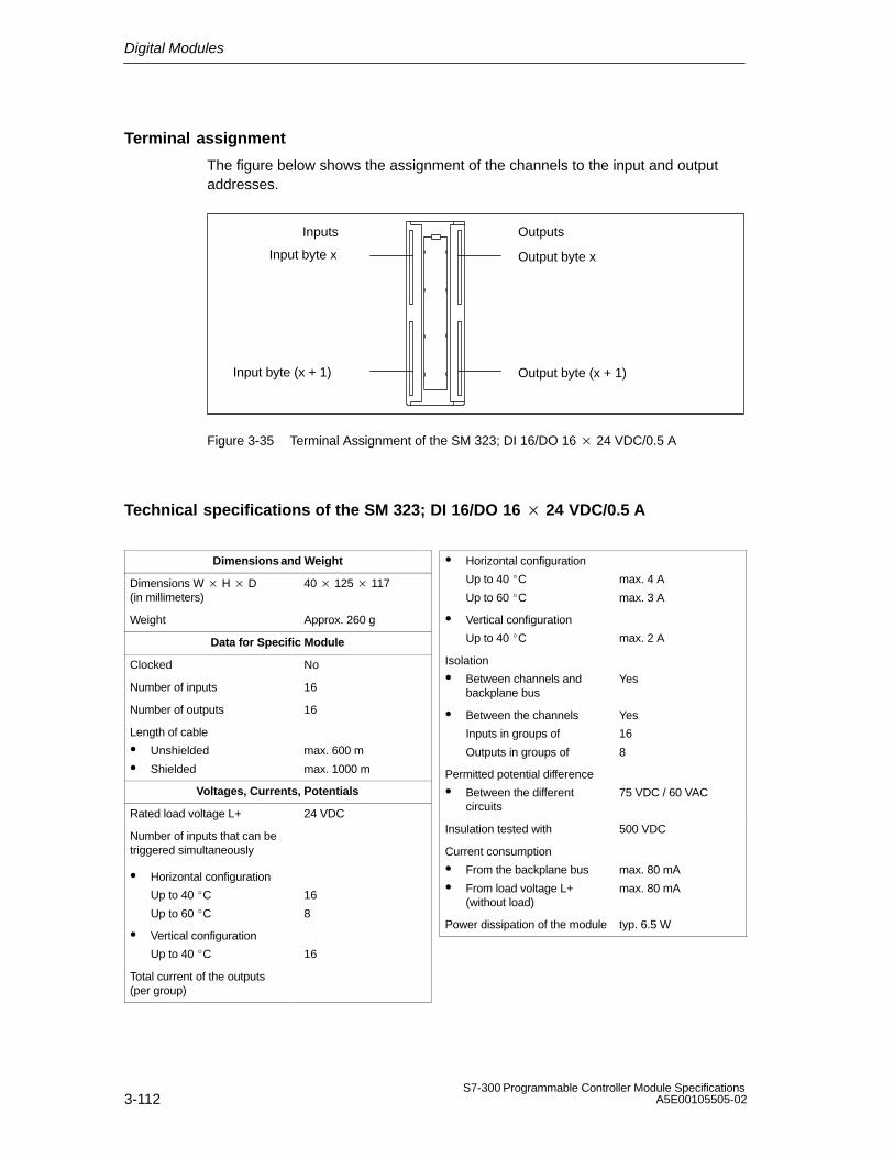
Digital Modules
3-112S7-300 Programmable Controller Module Specifications
A5E00105505-02
Terminal assignment
The figure below shows the assignment of the channels to the input and outputaddresses.
Input byte x
Input byte (x + 1)
Inputs Outputs
Output byte x
Output byte (x + 1)
Figure 3-35 Terminal Assignment of the SM 323; DI 16/DO 16 24 VDC/0.5 A
Technical specifications of the SM 323; DI 16/DO 16 24 VDC/0.5 A
Dimensions and Weight
Dimensions W H D(in millimeters)
40 125 117
Weight Approx. 260 g
Data for Specific Module
Clocked No
Number of inputs 16
Number of outputs 16
Length of cable
Unshielded
Shielded
max. 600 m
max. 1000 m
Voltages, Currents, Potentials
Rated load voltage L+ 24 VDC
Number of inputs that can betriggered simultaneously
Horizontal configuration
Up to 40 C
Up to 60 C
16
8
Vertical configuration
Up to 40 C 16
Total current of the outputs(per group)
Horizontal configuration
Up to 40 C
Up to 60 C
max. 4 A
max. 3 A
Vertical configuration
Up to 40 C max. 2 A
Isolation
Between channels andbackplane bus
Yes
Between the channels
Inputs in groups of
Outputs in groups of
Yes
16
8
Permitted potential difference
Between the differentcircuits
75 VDC / 60 VAC
Insulation tested with 500 VDC
Current consumption
From the backplane bus
From load voltage L+(without load)
max. 80 mA
max. 80 mA
Power dissipation of the module typ. 6.5 W

Digital Modules
3-113S7-300 Programmable Controller Module SpecificationsA5E00105505-02
Status, Interrupts, Diagnostics
Status display Green LED per channel
Interrupts None
Diagnostic functions None
Data for Selecting a Sensor
Input voltage
Rated value
For signal ”1”
For signal ”0”
24 VDC
13 to 30 V
–30 to + 5 V
Input current
At signal ”1” typ. 7 mA
Input delay
At ”0” to ”1”
At ”1” to ”0”
1.2 to 4.8 ms
1.2 to 4.8 ms
Input characteristic curve According to IEC61131, type 1
Connection of Two-WireBEROs
Permitted bias current
Possible
max. 1.5 mA
Data for Selecting an Actuator
Output voltage
At signal ”1” min. L + (–0.8 V)
Output current
At signal ”1”
Rated value
Permitted range
0.5 A
5 mA to 0.6 A
At signal ”0” (leakage current)
max. 0.5 mA
Output delay (for resistive load)
At ”0” to ”1”
At ”1” to ”0”
max. 100 s
max. 500 s
Load resistor range 48 to 4 k
Lamp load max. 5 W
Parallel connection of 2 outputs
For redundant triggering ofa load
Possible (only outputsof the same group)
To increase performance Not possible
Triggering a digital input Possible
Switch rate
For resistive load
Inductive load according toIEC 947-5-1, 13 DC
For lamp load
max. 100 Hz
max.0.5 Hz
max. 10 Hz
Limit (internal) of the inductivecircuit interruption voltage up
L + (–53 V), typ.
Short-circuit protection of theoutput
Yes, electronic
Threshold on 1 A, typ.

Digital Modules
3-114S7-300 Programmable Controller Module Specifications
A5E00105505-02
3.32 Digital Input/Output Module SM 323; DI 8/DO 8 24 VDC/0.5 A; (6ES7 323-1BHx1-0AA0)
Order number: ”Standard module”
6ES7 323-1BH01-0AA0
Order number: ”SIMATIC Outdoor module”
6ES7 323-1BH81-0AA0
Characteristics
The SM 323; DI 8/DO 8 24 VDC/0.5 A features the following characteristics:
8 inputs, isolated in groups of 8
8 outputs, isolated in groups of 8
24 VDC rated input voltage
24 VDC rated load voltage
Inputs suitable for switches and two / three / four-wire BEROs (proximityswitches)
Outputs suitable for solenoid valves, DC contactors and indicator lights
Using the module with high-speed counters
Please take note of the following information on the use of the module inconnection with high-speed counters:
Note
When connecting the 24 V power supply via a mechanical contact, the outputs ofthe SM 323; DI 8/DO 8 24 VDC/0.5 A carry a ”1” signal for approximately 50 sfor reasons associated with the circuitry.

Digital Modules
3-115S7-300 Programmable Controller Module SpecificationsA5E00105505-02
Terminal assignment and block diagram of the SM 323; DI 8/DO 8 24 VDC/0.5 A
Status display – green
Channel number
Backplane businterface
1M
2M
24V
24V
2L+
M
Figure 3-36 Module View and Block Diagram of Digital Input/Output Module SM 323;DI 8/DO 8 24 VDC/0.5 A

Digital Modules
3-116S7-300 Programmable Controller Module Specifications
A5E00105505-02
Technical specifications of the SM 323; DI 8/DO 8 24 VDC/0.5 A
Dimensions and Weight
Dimensions W H D(in millimeters)
40 125 117
Weight Approx. 200 g
Data for Specific Module
Supports clocked operation
No
Number of inputs 8
Number of outputs 8
Length of cable
Unshielded
Shielded
max. 600 m
max. 1000 m
Voltages, Currents, Potentials
Rated load voltage L+ 24 VDC
Number of inputs that can betriggered simultaneously
Horizontal configuration
Up to 60 C
Vertical configuration
Up to 40 C
8
8
Total current of the outputs (per group)
Horizontal configuration
Up to 60 C
Vertical configuration
Up to 40 C
max. 4 A
max. 4 A
Isolation
Between channels andbackplane bus
Yes
Between the channels
Inputs in groups of
Outputs in groups of
Yes
8
8
Permitted potential difference
Between the differentcircuits
75 VDC / 60 VAC
Insulation tested with 500 VDC
Current consumption
From the backplane bus
From load voltage L+(without load)
max. 40 mA
max. 40 mA
Power dissipation of the module typ. 3.5 W
Status, Interrupts, Diagnostics
Status display Green LED per channel
Interrupts None
Diagnostic functions None
Data for Selecting a Sensor
Input voltage
Rated value
For signal ”1”
For signal ”0”
24 VDC
13 to 30 V
–30 to 5 V
Input current
At signal ”1” typ. 7 mA
Input delay
At ”0” to ”1”
At ”1” to ”0”
1.2 to 4.8 ms
1.2 to 4.8 ms
Input characteristic curve According to IEC61131, type 1
Connection of Two-WireBEROs
Permitted bias current
Possible
max. 1.5 mA

Digital Modules
3-117S7-300 Programmable Controller Module SpecificationsA5E00105505-02
Data for Selecting an Actuator
Output voltage
At signal ”1” min. L + (–0.8 V)
Output current
At signal ”1”
Rated value
Permitted range
0.5 A
5 mA to 0.6 A
At signal ”0” (leakage current)
max. 0.5 mA
Output delay (for resistive load)
At ”0” to ”1”
At ”1” to ”0”
max. 100 s
max. 500 s
Load resistor range 48 to 4 k
Lamp load max. 5 W
Parallel connection of 2 outputs
For redundant triggering ofa load
Possible (only outputsof the same group)
To increase performance Not possible
Triggering a digital input Possible
Switch rate
For resistive load
Inductive load according toIEC 947-5-1, 13 DC
For lamp load
max. 100 Hz
max. 0.5 Hz
max. 10 Hz
Limit (internal) of the inductivecircuit interruption voltage up
L + (–53 V), typ.
Short-circuit protection of theoutput
Yes, electronic
Threshold on 1 A, typ.

Digital Modules
3-118S7-300 Programmable Controller Module Specifications
A5E00105505-02

4-1S7-300 Programmable Controller Module SpecificationsA5E00105505-02
Analog Modules
Changes and improvements compared to the previous edition of the ReferenceManual
This chapter describes all new analog modules. Furthermore, two new overviewsections will make it easier for you to access the information:
The ”Module Overview” section shows you the modules that are available,together with their most important characteristics, and helps you quickly to findthe module suitable for your task.
The section entitled ”Sequence of Steps from Choosing to Commissioning theModule” provides the answer to the question ”What must I do in succession tocommission the module quickly and successfully?
Structure of the chapter
The present chapter is broken down into the following subjects:
1. Overview containing the modules that are available here and a description
2. Information that is generally available – in other words, affects all analogmodules (such as parameter assignment and diagnostics)
3. Information that refers to specific modules (for example, characteristics,diagram of connections and block diagram, technical specifications and specialcharacteristics of the module):
a) for analog input modules
b) for analog output modules
c) for analog input/output modules
STEP 7 blocks for analog functions
You can use the blocks FC 105 ”SCALE” (Scale Values) and FC 106 ”UNSCALE”(Unscale Values) for reading and outputting analog values in STEP 7. You will findthe FCs in the standard library of STEP 7 in the subdirectory called”TI-S7-Converting Blocks” (for a description refer to the STEP 7 online Help for theFCs).
4

Analog Modules
4-2S7-300 Programmable Controller Module Specifications
A5E00105505-02
Additional information
Appendix A describes the structure of the parameter sets (data records 0, 1 and128) in the system data. You must be familiar with this configuration if you want tomodify the parameters of the modules in the STEP 7 user program.
Appendix B describes the structure of the diagnostic data (data records 0 and 1) inthe system data. You must be familiar with this configuration if you want toevaluate the diagnostic data of the modules in the STEP 7 user program.
In this chapter
Section Contents Page
4.1 Module Overview 4-3
4.2 Sequence of Steps from Choosing to Commissioning the AnalogModule
4-8
4.3 Analog Value Representation 4-10
4.4 Setting the Type of Measurement and Measuring Ranges ofAnalog Input Channels
4-31
4.5 Behavior of Analog Modules 4-34
4.6 Conversion, Cycle, Setting and Response Time of Analog Modules
4-39
4.7 Assigning Parameters to Analog Modules 4-43
4.8 Connecting Sensors/Transmitters to Analog Inputs 4-49
4.9 Connecting Voltage Sensors 4-54
4.10 Connecting Current Sensors 4-55
4.11 Connecting Resistance Thermometers and Resistors 4-57
4.12 Connecting Thermocouples 4-63
4.13 Connecting Loads/Actuators to Analog Outputs 4-72
4.14 Connecting Loads/Actuators to Voltage Outputs 4-73
4.15 Connecting Loads/Actuators to Current Outputs 4-76
4.16 Diagnostics of Analog Modules 4-77
4.17 Analog Module Interrupts 4-81
4.18 Analog Input Module SM 331; AI 8 16 bits;(6ES7 331-7NF00-0AB0)
4-83
4.19 Analog Input Module SM 331; AI 8 16 bits(6ES7 331-7NF10-0AB0)
4-92
4.20 Analog Input Module SM 331; AI 8 13 bits;(6ES7 331-1KF00-0AB0)
4-105
4.21 Analog Input Module SM 331; AI 8 12 bits;(6ES7 331-7KF02-0AB0)
4-111
4.22 Analog Input Module SM 331; AI 8 RTD(6ES7 331-7PF00-0AB0)
4-122

Analog Modules
4-3S7-300 Programmable Controller Module SpecificationsA5E00105505-02
Section PageContents
4.23 Analog Input Module SM 331; AI 8 TC(6ES7 331-7PF10-0AB0)
4-135
4.24 Analog Input Module SM 331; AI 212 bits;(6ES7 331-7KBx2-0AB0)
4-150
4.25 Analog Output Module SM 332; AO 8 12 bits(6ES7 332-5HF00-0AB0)
4-160
4.26 Analog Output Module SM 332; AO 4 16 bits;(6ES7 332-7ND01-0AB0)
4-166
4.27 Analog Output Module SM 332; AO 4 12 bits;(6ES7 332-5HD01-0AB0)
4-171
4.28 Analog Output Module SM 332; AO 2 12 bits;(6ES7 332-5HBx1-0AB0)
4-177
4.29 Analog Input/Output Module SM334;AI 4/AO 28/8 bits; (6ES7 334-0CE01-0AA0)
4-183
4.30 Analog Input/Output Module SM334; AI 4/AO 212 bits; (6ES7 334-0KE00-0AB0)
4-189
4.1 Module Overview
Introduction
The following tables summarize the most important characteristics of the analogmodules. This overview is intended to make it easy to choose the suitable modulefor your task.

Analog Modules
4-4S7-300 Programmable Controller Module Specifications
A5E00105505-02
Table 4-1 Analog Input Modules: Characteristics at a Glance
Module
Character-istics
SM 331; AI 816 bits
(-7NF00-)
SM 331; AI 816 bits
(-7NF10-)
SM 331; AI 813 bits
(-1KF00-)
SM 331; AI 812 bits
(-7KF02-)
Number of inputs
8 inputs in 4channel groups
8 inputs in 4channel groups
8 inputs in 8channel groups
8 inputs in 4channel groups
Resolution Adjustable for eachchannel group:
15 bits + sign
Adjustable for eachchannel group:
15 bits + sign
Adjustable for eachchannel group:
12 bits+sign
Adjustable for eachchannel group:
9 bits+sign
12 bits+sign
14 bits+sign
Measuringmethod
Adjustable for eachchannel group:
Voltage
Current
Adjustable for eachchannel group:
Voltage
Current
Adjustable for eachchannel:
Voltage
Current
Resistors
Temperature
Adjustable for eachchannel group:
Voltage
Current
Resistors
Temperature
Selection ofmeasuring range
Arbitrary, perchannel group
Arbitrary, perchannel group
Arbitrary,per channel
Arbitrary, perchannel group
Supports clocked operation
No No No No
Programmablediagnostics
Yes Yes No Yes
Diagnosticinterrupt
Adjustable Adjustable No Adjustable
Limit valuemonitoring
Adjustable for2 channels
Adjustable for8 channels
No Adjustable for2 channels
Hardwareinterrupt uponlimit violation
Adjustable Adjustable No Adjustable
Hardwareinterrupt at end ofcycle
No Yes No No
Potentialrelationships
Galvanic isolationto:
CPU
Galvanic isolationto:
CPU
Galvanic isolationto:
CPU
Galvanic isolationto:
CPU
Load voltage(not for 2-DMU)
Permittedpotentialdifferencebetween theinputs (ECM)
50 VDC 60 VDC 2.0 VDC 2.5 VDC
Special features – - – –
Sign Sign2-DMU Two-wire transmitter

Analog Modules
4-5S7-300 Programmable Controller Module SpecificationsA5E00105505-02
Table 4-2 Analog input modules: Characteristics at a glance (continued)
Module
Characteristics
SM 331; AI 8RTD
(-7PF00-)
SM 331; AI 8TC
(-7PF10-)
SM 331; AI 212 bits
(-7KBx2-)
Number of inputs
8 inputs in 4 channelgroups
8 inputs in 4 channelgroups
2 inputs in 1 channelgroup
Resolution Adjustable for eachchannel group:
15 bits + sign
Adjustable for eachchannel group:
15 bits + sign
Adjustable for eachchannel group:
9 bits+sign
12 bits+sign
14 bits+sign
Measuring method Adjustable for eachchannel group:
Resistors
Temperature
Adjustable for eachchannel group:
Temperature
Adjustable for eachchannel group:
Voltage
Current
Resistors
Temperature
Selection ofmeasuring range
Arbitrary, per channelgroup
Arbitrary, per channelgroup
Arbitrary, per channelgroup
Programmablediagnostics
Yes Yes Yes
Supports clockedoperation
No No No
Diagnostic Interrupt Adjustable Adjustable Adjustable
Limit valuemonitoring
Adjustable for 8 channels Adjustable for 8 channels Adjustable for 1 channel
Hardware interruptupon limit violation
Adjustable Adjustable Adjustable
Hardware interruptat end of cycle
Adjustable Adjustable No
Potentialrelationships
Galvanic isolation to:
CPU
Galvanic isolation to:
CPU
Galvanic isolation to:
CPU
Load voltage (not for2-DMU)
Permitted potentialdifference betweenthe inputs (ECM)
75 VDC / 60 VAC 75 VDC / 60 VAC 2.5 VDC
Special features – –
Sign Sign2-DMU Two-wire transmitter

Analog Modules
4-6S7-300 Programmable Controller Module Specifications
A5E00105505-02
Table 4-3 Analog Output Modules: Characteristics at a Glance
Module
Charac-teristics
SM 332; AO 812 bits
(-5HF00-)
SM 332; AO 416 bits
(-7ND01-)
SM 332; AO 4 12 bits
(-5HD01-)
SM 332; AO 2 12 bits
(-5HBx1-)
Number ofoutputs
8 outputs in 8channel groups
4 outputs in 4channel groups
4 outputs in 4channel groups
2 output in 2channels groups
Resolution 12 bits 16 bits 12 bits 12 bits
Output type Channel bychannel:
Voltage
Current
Channel bychannel:
Voltage
Current
Channel bychannel:
Voltage
Current
Channel bychannel:
Voltage
Current
Supports clocked operation
No Yes No No
Programmablediagnostics
Yes Yes Yes Yes
Diagnosticinterrupt
Adjustable Adjustable Adjustable Adjustable
Substitute valueoutput
No Adjustable Adjustable Adjustable
Potentialrelationships
Galvanic isolationbetween:
CPU
Of the loadvoltage
Galvanic isolationbetween:
CPU andchannel
The channels
Output and L+,M
CPU and L+, M
Galvanic isolationto:
CPU
Of the loadvoltage
Galvanic isolationto:
CPU
Of the loadvoltage
Special features – – – –

Analog Modules
4-7S7-300 Programmable Controller Module SpecificationsA5E00105505-02
Table 4-4 Analog Input/Output Modules: Characteristics at a Glance
Module
Characteristics
SM 334; AI 4/AO 2 8/8 bits
(-0CE01-)
SM 334; AI 4/AO 2 12 bits
(-0KE00-)
Number of inputs 4 inputs in 1 channel group 4 inputs in 2 channel groups
Number of outputs 2 outputs in 1 channel group 2 outputs in 1 channel group
Resolution 8 bits 12 bits + sign
Measuring Method Adjustable for each channelgroup:
Voltage
Current
Adjustable for each channelgroup:
Voltage
Resistors
Temperature
Output type Channel by channel:
Voltage
Current
Channel by channel:
Voltage
Supports clocked operation
No No
Programmable diagnostics No No
Diagnostic Interrupt No No
Limit value monitoring No No
Hardware interrupt upon limitviolation
No No
Hardware interrupt at end ofcycle
No No
Substitute value output No No
Potential relationships Non-isolated to CPU
Galvanic isolation to loadvoltage
Galvanic isolation to:
CPU
Of the load voltage
Special features Not parameterizable, setting ofmeasurement and output type bymeans of wiring
–
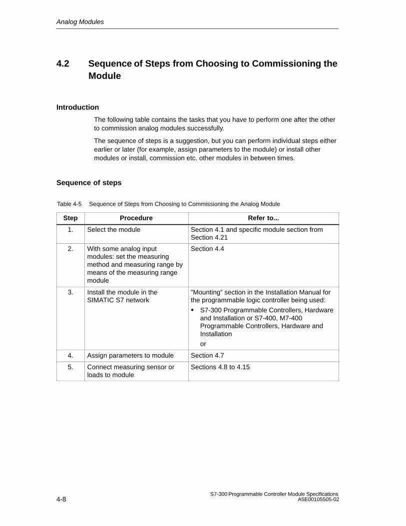
Analog Modules
4-8S7-300 Programmable Controller Module Specifications
A5E00105505-02
4.2 Sequence of Steps from Choosing to Commissioning theModule
Introduction
The following table contains the tasks that you have to perform one after the otherto commission analog modules successfully.
The sequence of steps is a suggestion, but you can perform individual steps eitherearlier or later (for example, assign parameters to the module) or install othermodules or install, commission etc. other modules in between times.
Sequence of steps
Table 4-5 Sequence of Steps from Choosing to Commissioning the Analog Module
Step Procedure Refer to...
1. Select the module Section 4.1 and specific module section fromSection 4.21
2. With some analog inputmodules: set the measuringmethod and measuring range bymeans of the measuring rangemodule
Section 4.4
3. Install the module in theSIMATIC S7 network
”Mounting” section in the Installation Manual forthe programmable logic controller being used:
S7-300 Programmable Controllers, Hardwareand Installation or S7-400, M7-400Programmable Controllers, Hardware andInstallation
or
4. Assign parameters to module Section 4.7
5. Connect measuring sensor orloads to module
Sections 4.8 to 4.15
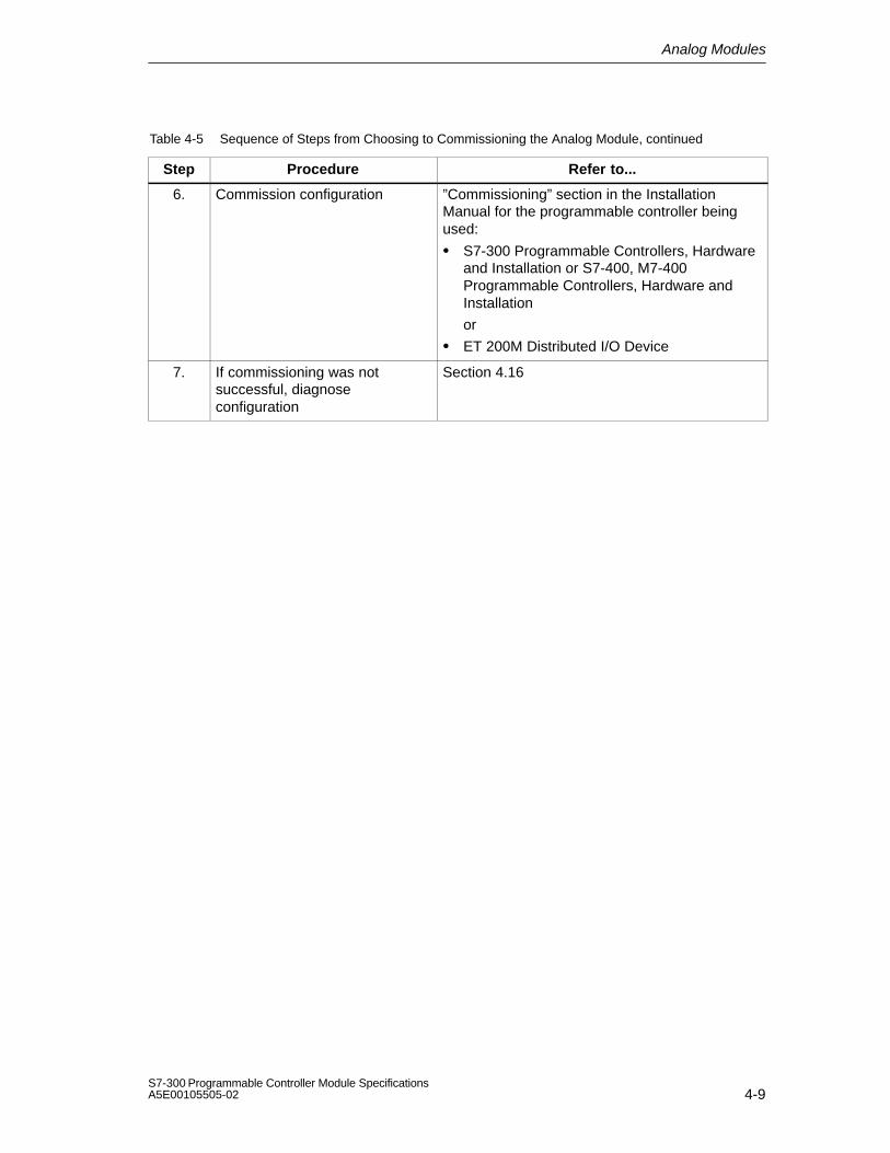
Analog Modules
4-9S7-300 Programmable Controller Module SpecificationsA5E00105505-02
Table 4-5 Sequence of Steps from Choosing to Commissioning the Analog Module, continued
Step Refer to...Procedure
6. Commission configuration ”Commissioning” section in the InstallationManual for the programmable controller beingused:
S7-300 Programmable Controllers, Hardwareand Installation or S7-400, M7-400Programmable Controllers, Hardware andInstallation
or
ET 200M Distributed I/O Device
7. If commissioning was notsuccessful, diagnoseconfiguration
Section 4.16

Analog Modules
4-10S7-300 Programmable Controller Module Specifications
A5E00105505-02
4.3 Analog Value Representation
Introduction
This section describes the analog values for all the measuring ranges and outputranges which you can use with the analog modules.
Converting analog values
The CPU processes the analog values in binary form only.
Analog input modules convert the analog process signal into digital form.
Analog output modules convert the digital output value into an analog signal.
Analog value representation with 16-bit resolution
The digitized analog value is the same for both input and output values having thesame nominal range. The analog values are represented as a fixed-point numberin two’s complement. The resulting assignment is as follows:
Bit 15 14 13 12 11 10 9 8 7 6 5 4 3 2 1 0
Value of bits 215 214 213 212 211 210 29 28 27 26 25 24 23 22 21 20
Sign
The sign of the analog value is always contained in bit number 15:
”0”
”1”
Resolution less than 16 bits
If the resolution of an analog module has fewer than 16 bits, the analog value isstored left-justified on the module. The lower-order bit positions not used arepadded with zeros (”0”).

Analog Modules
4-11S7-300 Programmable Controller Module SpecificationsA5E00105505-02
Example
In the following example you can see how the positions not padded with ”0” arewritten for low resolution.
Table 4-6 Example: Bit Pattern of a 16-Bit and a 13-Bit Analog Value
Resolution Analog value
Bit 15 14 13 12 11 10 9 8 7 6 5 4 3 2 1 0
16-bit analog value 0 1 0 0 0 1 1 0 0 1 1 1 0 0 1 1
13-bit analog value 0 1 0 0 0 1 1 0 0 1 1 1 0 0 0 0
4.3.1 Analog Value Representation for Analog Input Channels
Introduction
The tables in this chapter contain the measured value representations for thevarious measuring ranges of the analog input modules. The values in the tablesapply to all modules with the corresponding measuring ranges.
Notes for readers of the tables
Tables 4-8 to 4-9 contain the binary representation of the measured values.
Since the binary representation of the measured values is always the same,starting at 4-10 these tables only contain the measured values and the units.

Analog Modules
4-12S7-300 Programmable Controller Module Specifications
A5E00105505-02
Measured-value resolution
The resolution of the analog values may differ, depending on the analog moduleand its parameterization. With resolutions < 15 bits, the bits indicated by ”x” are setto ”0”.
Note: This resolution does not apply to temperature values. The convertedtemperature values are the result of a conversion in the analog module (see Tables4-16 to 4-31).
Table 4-7 Possible Analog Value Resolutions
Resolution Units Analog value in bits (+ sign)
decimal hexadecimal High-order byte Low-order byte
8 128 80H Sign 0 0 0 0 0 0 0 1 x x x x x x x
9 64 40H Sign 0 0 0 0 0 0 0 0 1 x x x x x x
10 32 20H Sign 0 0 0 0 0 0 0 0 0 1 x x x x x
11 16 10H Sign 0 0 0 0 0 0 0 0 0 0 1 x x x x
12 8 8H Sign 0 0 0 0 0 0 0 0 0 0 0 1 x x x
13 4 4H Sign 0 0 0 0 0 0 0 0 0 0 0 0 1 x x
14 2 2H Sign 0 0 0 0 0 0 0 0 0 0 0 0 0 1 x
15 1 1H Sign 0 0 0 0 0 0 0 0 0 0 0 0 0 0 1

Analog Modules
4-13S7-300 Programmable Controller Module SpecificationsA5E00105505-02
Binary representation of the input ranges
The input ranges shown in Tables 4-8 to 4-9 are defined in two’s complementrepresentation:
Table 4-8 Bipolar Input Ranges
Units Measured Data Word RangeValue in % 215 214 213 212 211 210 29 28 27 26 25 24 23 22 21 20
32767 118.515 0 1 1 1 1 1 1 1 1 1 1 1 1 1 1 1 Overflow
32511 117.589 0 1 1 1 1 1 1 0 1 1 1 1 1 1 1 1 Overrange
27649 100.004 0 1 1 0 1 1 0 0 0 0 0 0 0 0 0 1
27648 100.000 0 1 1 0 1 1 0 0 0 0 0 0 0 0 0 0
1 0.003617 0 0 0 0 0 0 0 0 0 0 0 0 0 0 0 1
0 0.000 0 0 0 0 0 0 0 0 0 0 0 0 0 0 0 0 Rated
–1 –0.003617 1 1 1 1 1 1 1 1 1 1 1 1 1 1 1 1range
–27648 –100.000 1 0 0 1 0 1 0 0 0 0 0 0 0 0 0 0
–27649 –100.004 1 0 0 1 0 0 1 1 1 1 1 1 1 1 1 1 Under-
–32512 –117.593 1 0 0 0 0 0 0 1 0 0 0 0 0 0 0 0range
–32768 –117.596 1 0 0 0 0 0 0 0 0 0 0 0 0 0 0 0 Underflow
Table 4-9 Unipolar Input Ranges
Units Measured Data Word RangeValue in % 215 214 213 212 211 210 29 28 27 26 25 24 23 22 21 20
32767 118.515 0 1 1 1 1 1 1 1 1 1 1 1 1 1 1 1 Overflow
32511 117.589 0 1 1 1 1 1 1 0 1 1 1 1 1 1 1 1 Over-
27649 100.004 0 1 1 0 1 1 0 0 0 0 0 0 0 0 0 1 range
27648 100.000 0 1 1 0 1 1 0 0 0 0 0 0 0 0 0 0
1 0.003617 0 0 0 0 0 0 0 0 0 0 0 0 0 0 0 1 Ratedrange
0 0.000 0 0 0 0 0 0 0 0 0 0 0 0 0 0 0 0
–1 –0.003617 1 1 1 1 1 1 1 1 1 1 1 1 1 1 1 1 Under-
–4864 –17.593 1 1 1 0 1 1 0 1 0 0 0 0 0 0 0 0 range
–32768 –17.596 1 0 0 0 0 0 0 0 0 0 0 0 0 0 0 0 Underflow

Analog Modules
4-14S7-300 Programmable Controller Module Specifications
A5E00105505-02
Analog Value Representation in Voltage Measuring Ranges
Table 4-10 Analog Value Representation in Voltage Measuring Ranges ± 10 V to ± 1 V
System Voltage Measuring Range
Dec. Hex. ±10 V ±5 V ±2.5 V ±1 V
118.515 % 32767 7FFF 11.851 V 5.926 V 2.963 V 1.185 V Overflow
117.593% 32512 7F00
117.589% 32511 7EFF 11.759 V 5.879 V 2.940 V 1.176 V Overrange
27649 6C01
Overrange
100.000% 27648 6C00 10 V 5 V 2.5 V 1 V
75.000 % 20736 5100 7.5 V 3.75 V 1.875 V 0.75 V
0.003617% 1 1 361.7 V 180.8 V 90.4 V 36.17 V
0 % 0 0 0 V 0 V 0 V 0 V Rated range
–1 FFFF
–75.00 % –20736 AF00 –7.5 V –3.75 V –1.875 V –0.75 V
–100.000% –27648 9400 –10 V –5 V –2.5 V –1 V
–27649 93FF
–117.593% –32512 8100 –11.759 V –5.879 V –2.940 V –1.176 VUnderrange
–117.596 % –32513 80FF Underflow
–118.519% –32768 8000 –11.851 V –5.926 V –2.963 V –1.185 V

Analog Modules
4-15S7-300 Programmable Controller Module SpecificationsA5E00105505-02
Table 4-11 Analog Value Representation in Voltage Measuring Ranges ± 500 mV to ± 80 mV
System Voltage Measuring Range
Dec. Hex. ±500 mV ±250 mV ±80 mV
118.515 % 32767 7FFF 592.6 mV 296.3 mV 94.8 mV Overflow
117.593% 32512 7F00
117.589% 32511 7EFF 587.9 mV 294.0 mV 94.1 mV Overrange
27649 6C01
100.000% 27648 6C00 500 mV 250 mV 80 mV
75.00 % 20736 5100 375 mV 187.5 mV 60 mV
0.003617% 1 1 18.08 V 9.04 V 2.89 V
0 % 0 0 0 mV 0 mV 0 mV Rated range
–1 FFFF
–75.00 % –20736 AF00 –375 mV –187.5 mV –60 mV
–100.000% –27648 9400 –500 mV –250 mV –80 mV
–27649 93FF Underrange
–117.593% –32512 8100 –587.9 mV –294.0 mV –94.1 mV
–117.596 % –32513 80FF Underflow
–118.519% –32768 8000 –592.6 mV –296.3 mV –94.8 mV
Table 4-12 Analog Value Representation in Voltage Measuring Ranges 1 to 5 V and 0 to 10V
System Voltage Measuring Range
Dec. Hex. 1 to 5 V 0 to 10 V
118.515 % 32767 7FFF 5.741 V 11.852 V
117.593% 32512 7F00Overflow
117.589% 32511 7EFF 5.704 V 11.759 V
27649 6C01Overrange
100.000% 27648 6C00 5 V 10 V
75% 20736 5100 3.75 V 7.5 V
0.003617% 1 1 1 V + 144.7 V 0 V + 361.7 VRated range
0 % 0 0 1 V 0 V
–1 FFFF
–17.593% –4864 ED00 0.296 V Negative valuesUnderrange
–4865 ECFFNegative valuesnot possible
–17.596 % –32768 8000Underflow
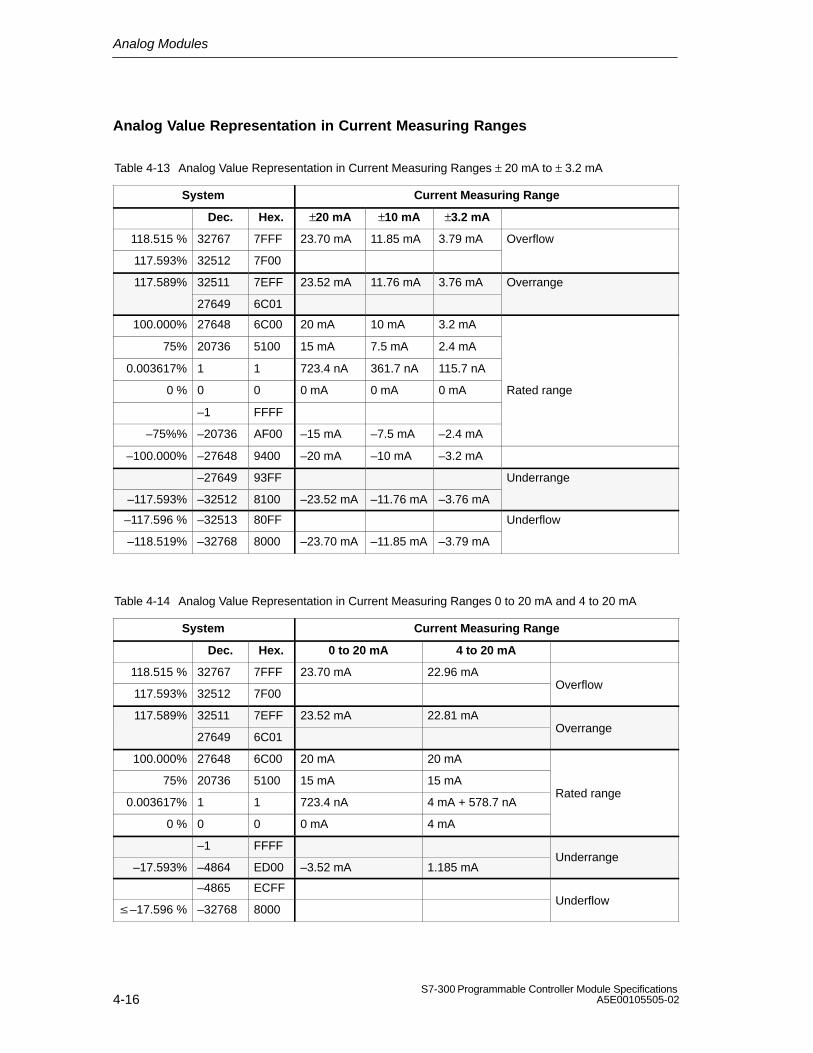
Analog Modules
4-16S7-300 Programmable Controller Module Specifications
A5E00105505-02
Analog Value Representation in Current Measuring Ranges
Table 4-13 Analog Value Representation in Current Measuring Ranges ± 20 mA to ± 3.2 mA
System Current Measuring Range
Dec. Hex. ±20 mA ±10 mA ±3.2 mA
118.515 % 32767 7FFF 23.70 mA 11.85 mA 3.79 mA Overflow
117.593% 32512 7F00
117.589% 32511 7EFF 23.52 mA 11.76 mA 3.76 mA Overrange
27649 6C01
100.000% 27648 6C00 20 mA 10 mA 3.2 mA
75% 20736 5100 15 mA 7.5 mA 2.4 mA
0.003617% 1 1 723.4 nA 361.7 nA 115.7 nA
0 % 0 0 0 mA 0 mA 0 mA Rated range
–1 FFFF
–75%% –20736 AF00 –15 mA –7.5 mA –2.4 mA
–100.000% –27648 9400 –20 mA –10 mA –3.2 mA
–27649 93FF Underrange
–117.593% –32512 8100 –23.52 mA –11.76 mA –3.76 mA
–117.596 % –32513 80FF Underflow
–118.519% –32768 8000 –23.70 mA –11.85 mA –3.79 mA
Table 4-14 Analog Value Representation in Current Measuring Ranges 0 to 20 mA and 4 to 20 mA
System Current Measuring Range
Dec. Hex. 0 to 20 mA 4 to 20 mA
118.515 % 32767 7FFF 23.70 mA 22.96 mA
117.593% 32512 7F00Overflow
117.589% 32511 7EFF 23.52 mA 22.81 mA
27649 6C01Overrange
100.000% 27648 6C00 20 mA 20 mA
75% 20736 5100 15 mA 15 mA
0.003617% 1 1 723.4 nA 4 mA + 578.7 nARated range
0 % 0 0 0 mA 4 mA
–1 FFFF
–17.593% –4864 ED00 –3.52 mA 1.185 mAUnderrange
–4865 ECFF
–17.596 % –32768 8000Underflow

Analog Modules
4-17S7-300 Programmable Controller Module SpecificationsA5E00105505-02
Analog Value Representation for Resistance-Type Transmitters
Table 4-15 Analog Value Representation for Resistance Type Transmitters from 10 k and from 150 to600
System Resistance-Type Transmitter Range
Dec. Hex. 10 k 150 300 600
118.515 % 32767 7FFF 11.852k 177.77 355.54 711.09 Overflow
117.593% 32512 7F00 150.01 300.01 600.02
117.589% 32511 7EFF 11.759k
176.38
352.77 705.53 Overrange
27649 6C01
100.000% 27648 6C00 10 k 150 300 600
75% 20736 5100 7.5 k 112.5 225 450
0.003617% 1 1 361.7m 5.43 m 10.85m 21.70m Rated range
0 % 0 0 0 0 0 0
(neg. values physically Underrange(neg. values physically not possible)
Analog value representation for RTD Resistance Temperature Detectors Pt x00standard
Table 4-16 Analog Value Representation for RTD Resistance Temperature Detectors Pt 100, 200, 500,1000
Pt x00standard
Units Pt x00standard
Units Pt x00standard
Unitsstandard
in C(1 digit=0.1C)
deci-mal
hexa-decimal
standardin F
(1 digit=0.1 F)
deci-mal
hexa-decimal
standardin K
(1 digit =0.1 K)
deci-mal
hexa-decimal
Range
> 1000.0 32767 7FFFH > 1832.0 32767 7FFFH > 1273.2 32767 7FFFH Overflow
1000.0
:
850.1
10000
:
8501
2710H
:
2135H
1832.0
:
1562.1
18320
:
15621
4790H
:
3D05H
1273.2
:
1123.3
12732
:
11233
31BCH
:
2BE1H
Overrange
850.0
:
–200.0
8500
:
–2000
2134H
:
F830H
1562.0
:
–328.0
15620
:
–3280
3D04H
:
F330H
1123.2
:
73.2
11232
:
732
2BE0H
:
2DCH
Rated range
–200.1
:
–243.0
–2001
:
–2430
F82FH
:
F682H
–328.1
:
–405.4
–3281
:
–4054
F32FH
:
F02AH
73.1
:
30.2
731
:
302
2DBH
:
12EH
Underrange
< –243.0 –32768 8000H < –405.4 –32768 8000H < 30.2 32768 8000H Underflow

Analog Modules
4-18S7-300 Programmable Controller Module Specifications
A5E00105505-02
Analog value representation for RTD Resistance Temperature Detectors Pt x00climate
Table 4-17 Analog Value Representation for RTD Resistance Temperature Detectors Pt 100, 200, 500,1000
Pt x00 cli-mate
Units Pt x00 cli-mate
Unitsmate in C
(1 digit =0.01C)
deci-mal
hexa-decimal
mate in F
(1 digit =0.01F)
deci-mal
hexa-decimal
Range
>155.00 32767 7FFFH >311.00 32767 7FFFH Overflow
155.00
:
130.01
15500
:
13001
3C8CH
:
32C9H
311.00
:
266.01
31100
:
26601
797CH
:
67E9H
Overrange
130.00
:
–120.00
13000
:
–12000
32C8H
:
D120H
266.00
:
–184.00
26600
:
–18400
67E8H
:
B820H
Rated range
–120.01
:
–145.00
–12001
:
–14500
D11FH
:
C75CH
–184.01
:
–229.00
–18401
:
–22900
B81FH
:
A68CH
Underrange
< –145.00 –32768 8000H < –229.00 –32768 8000H Underflow
Analog value representation for RTD Resistance Temperature Detectors Ni x00standard
Table 4-18 Analog Value Representation for RTD Resistance Temperature Detectors Ni100, 120, 200,500, 1000
Ni x00standard
Units Ni x00standard
Units Ni x00standard
Unitsstandard
in C(1 digit =
0.1C)
deci-mal
hexa-decimal
standardin F
(1 digit =0.1 F)
deci-mal
hexa-decimal
standardin K
(1 digit =0.1 K)
deci-mal
hexa-decimal
Range
>295.0 32767 7FFFH >563.0 32767 7FFFH >568.2 32767 7FFFH Overflow
295.0
:
250.1
2950
:
2501
B86H
:
9C5H
563.0
:
482.1
5630
:
4821
15FEH
:
12D5H
568.2
:
523.3
5682
:
5233
1632H
:
1471H
Overrange
250.0
:
–60.0
2500
:
–600
9C4H
:
FDA8H
482.0
:
–76.0
4820
:
–760
12D4H
:
FD08H
523.2
:
213.2
5232
:
2132
1470H
:
854H
Rated range
–60.1
:
–105.0
–601
:
–1050
FDA7H
:
FBE6H
–76.1
:
–157.0
–761
:
–1570
FD07H
:
F9DEH
213.1
:
168.2
2131
:
1682
853H
:
692H
Underrange
< –105.0 –32768 8000H < –157.0 –32768 8000H <168.2 32768 8000H Underflow

Analog Modules
4-19S7-300 Programmable Controller Module SpecificationsA5E00105505-02
Analog value representation for RTD Resistance Temperature Detectors Ni x00climate
Table 4-19 Analog Value Representation for RTD Resistance Temperature Detectors Ni 100, 120, 200,500, 1000
Ni x00 cli-mate
Units Ni x00 cli-mate
Unitsmate in C
(1 digit =0.01C)
deci-mal
hexa-decimal
mate in F
(1 digit =0.01F)
deci-mal
hexa-decimal
Range
> 295.00 32767 7FFFH >325.11 32767 7FFFH Overflow
295.00
:
250.01
29500
:
25001
733CH
:
61A9H
327.66
:
280.01
32766
:
28001
7FFEH
:
6D61H
Overrange
250.00
:
–60.00
25000
:
–6000
61A8H
:
E890H
280.00
:
–76.00
28000
:
–7600
6D60H
:
E250H
Rated range
–60.01
:
–105.00
–6001
:
–10500
E88FH
:
D6FCH
–76.01
:
–157.00
–7601
:
–15700
E24FH
:
C2ACH
Underrange
< –105.00 –32768 8000H < –157.00 –32768 8000H Underflow
Analog value representation for RTD Resistance Temperature Detectors Cu 10standard
Table 4-20 Analog Value Representation for RTD Resistance Temperature Detectors Cu 10
Cu 10standard
Units Cu 10standard
Units Cu 10standard
Unitsstandard
in C(1 digit =0.01C)
deci-mal
hexa-decimal
standardin F
(1 digit =0.01 F)
deci-mal
hexa-decimal
standardin K
(1 digit =0.01 K)
deci-mal
hexa-decimal
Range
> 312.0 32767 7FFFH >593.6 32767 7FFFH >585.2 32767 7FFFH Overflow
312.0
:
260.1
3120
:
2601
C30H
:
A29H
593.6
:
500.1
5936
:
5001
1730H
:
12D5H
585.2
:
533.3
5852
:
5333
16DCH
:
14D5H
Overrange
260.0
:
–200.0
2600
:
–2000
A28H
:
F830H
500.0
:
–328.0
5000
:
–3280
1389H
:
F330H
533.2
:
73.2
5332
:
732
14D4H
:
2DCH
Rated range
–200.1
:
–240.0
–2001
:
–2400
F82FH
:
F6A0H
–328.1
:
–400.0
–3281
:
–4000
F32FH
:
F060H
73.1
:
33.2
731
:
332
2DBH
:
14CH
Underrange
< –240.0 –32768 8000H < –400.0 –32768 8000H <33.2 32768 8000H Underflow

Analog Modules
4-20S7-300 Programmable Controller Module Specifications
A5E00105505-02
Analog value representation for RTD Resistance Temperature Detectors Cu 10climate
Table 4-21 Analog Value Representation for RTD Resistance Temperature Detectors Cu 10
Cu 10 cli-mate
Units Cu 10 cli-mate
Unitsmatein C
(1 digit =0.01C)
deci-mal
hexa-decimal
matein F
(1 digit =0.01F)
deci-mal
hexa-decimal
Range
> 180.00 32767 7FFFH >325.11 32767 7FFFH Overflow
180.00
:
150.01
18000
:
15001
4650H
:
3A99H
327.66
:
280.01
32766
:
28001
7FFEH
:
6D61AH
Overrange
150.00
:
–50.00
15000
:
–5000
3A98H
:
EC78H
280.00
:
–58.00
28000
:
–5800
6D60H
:
E958H
Rated range
–50.01
:
–60.00
–5001
:
–6000
EC77H
:
E890H
–58.01
:
–76.00
–5801
:
–7600
E957H
:
E250H
Underrange
< –60.00 –32768 8000H < –76.00 –32768 8000H Underflow
Analog value representation for thermocouples type B
Table 4-22 Analog Value Representation for Thermocouples Type B
Units Units UnitsType Bin C deci-
malhexa-
decimal
Type B in F deci-
malhexa-
decimal
Type B in K deci-
malhexa-
decimalRange
>2070.0 32767 7FFFH >3276.6 32767 7FFFH >2343.2 32767 7FFFH Overflow
2070.0
:
1821.0
20700
:
18210
50DCH
:
4722H
3276.6
:
2786.6
32766
:
27866
7FFEH
:
6CDAH
2343.2
:
2094.2
23432
:
20942
5B88H
:
51CEH
Overrange
1820.0
:
0.0
18200
:
0
4718H
:
0000H
2786.5
:
32.0
27865
:
320
6CD9H
:
0140H
2093.2
:
273.2
20932
:
2732
51C4H
:
0AACH
Rated range
:
–120.0
:
–1200
:
FB50H
:
–184.0
:
–1840
:
F8D0H
:
153.2
:
1532
:
05FCH
Underrange
< –120.0 –32768 8000H < –184.0 –32768 8000H <153.2 32768 8000H Underflow

Analog Modules
4-21S7-300 Programmable Controller Module SpecificationsA5E00105505-02
Analog Value Representation for Thermocouples type C
Table 4-23 Analog Value Representation for Thermocouples Type C
Units UnitsType C
in C deci-mal
hexa-decimal
Type C in F deci-
malhexa-
decimalRange
>2500.0 32767 7FFFH >3276.6 32767 7FFFH Overflow
2500.0
:
2315.1
25000
:
23151
61A8H
:
5A6FH
3276.6
:
2786.6
32766
:
27866
7FFEH
:
6CDAH
Overrange
2315.0
:
0.0
23150
:
0
5A6EH
:
0000H
2786.5
:
32.0
27865
:
320
6CD9H
:
0140H
Rated range
0.1
:
–120.0
–1
:
–1200
FFFFH
:
FB50H
31.9
:
–184.0
319
:
–1840
013FH
:
F8D0H
Underrange
< –120.0 –32768 8000H < –184.0 –32768 8000H Underflow
Analog Value Representation for Thermocouples type E
Table 4-24 Analog Value Representation for Thermocouples Type E
Units Units UnitsType E
in C deci-mal
hexa-decimal
Type E in F deci-
malhexa-
decimal
Type E in K deci-
malhexa-
decimalRange
> 1200.0 32767 7FFFH > 2192,0 32767 7FFFH > 1473.2 32767 7FFFH Overflow
1200.0
:
1000.1
12000
:
10001
2EE0H
:
2711H
2192.0
:
1833.8
21920
:
18338
55A0H
:
47A2H
1473.2
:
1274.2
14732
:
12742
398CH
:
31C6H
Overrange
1000.0
:
–270.0
10000
:
–2700
2710H
:
F574H
1832.0
:
–454.0
18320
:
–4540
4790H
:
EE44H
1273.2
:
0
12732
:
0
31BCH
:
0000H
Rated range
< –270.0 < –2700 H < –454.0 < –4540 <EE44H <0 <0 <0000H Underflow
In the case of incorrect wiring (e. g. polarity reversal or open inputs) or of a sensor error in the negativerange (e. g. incorrect thermocouple type), the analog input module signals underflow ...
... of F0C4H and outputs 8000H. ... of FB70H and outputs 8000H. ... of E5D4H and outputs 8000H.
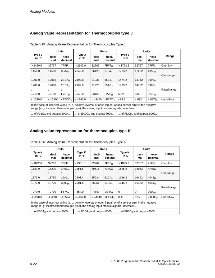
Analog Modules
4-22S7-300 Programmable Controller Module Specifications
A5E00105505-02
Analog Value Representation for Thermocouples type J
Table 4-25 Analog Value Representation for Thermocouples Type J
Units Units UnitsType J in C deci-
malhexa-
decimal
Type J in F deci-
malhexa-
decimal
Type J in K deci-
malhexa-
decimalRange
> 1450.0 32767 7FFFH > 2642,0 32767 7FFFH > 1723.2 32767 7FFFH Overflow
1450.0
:
1201.0
14500
:
12010
38A4H
:
2EEAH
2642.0
:
2193.8
26420
:
21938
6734H
:
55B2H
1723.2
:
1474.2
17232
:
14742
4350H
:
3996H
Overrange
1200.0
:
–210.0
12000
:
–2100
2EE0H
:
F7CCH
2192.0
:
–346.0
21920
:
–3460
55A0H
:
F27CH
1473.2
:
63.2
14732
:
632
398CH
:
0278H
Rated range
< –210.0 < –2100 <F7CCH < –346.0 < –3460 <F27CH <63.2 < 632 < 0278H Underflow
In the case of incorrect wiring (e. g. polarity reversal or open inputs) or of a sensor error in the negativerange (e. g. incorrect thermocouple type), the analog input module signals underflow ...
... of F31CH and outputs 8000H. ... of EA0CH and outputs 8000H. ... of FDC8H and outputs 8000H.
Analog value representation for thermocouples type K
Table 4-26 Analog Value Representation for Thermocouples Type K
Units Units UnitsType K
in C deci-mal
hexa-decimal
Type K in F deci-
malhexa-
decimal
Type K in K deci-
malhexa-
decimalRange
> 1622.0 32767 7FFFH >2951.6 32767 7FFFH > 1895.2 32767 7FFFH Overflow
1622.0
:
1373.0
16220
:
13730
3F5CH
:
35A2H
2951.6
:
2503.4
29516
:
25034
734CH
:
61CAH
1895.2
:
1646.2
18952
:
16462
4A08H
:
404EH
Overrange
1372.0
:
–270.0
13720
:
–2700
3598H
:
F574H
2501.6
:
–454.0
25061
:
–4540
61B8H
:
EE44H
1645.2
:
0
16452
:
0
4044H
:
0000H
Rated range
< –270.0 < –2700 < F574H < –454.0 < –4540 <EE44H 0 % 0 % < 0000H Underflow
In the case of incorrect wiring (e. g. polarity reversal or open inputs) or of a sensor error in the negativerange (e. g. incorrect thermocouple type), the analog input module signals underflow ...
... of F0C4H and outputs 8000H. ... of E5D4H and outputs 8000H. ... of FB70H and outputs 8000H.

Analog Modules
4-23S7-300 Programmable Controller Module SpecificationsA5E00105505-02
Analog value representation for thermocouples type L
Table 4-27 Analog Value Representation for Thermocouples Type L
Units Units UnitsType L
in C deci-mal
hexa-decimal
Type L in F deci-
malhexa-
decimal
Type L in K deci-
malhexa-
decimalRange
>1150.0 32767 7FFFH >2102.0 32767 7FFFH >1423.2 32767 7FFFH Overflow
1150.0
:
901.0
11500
:
9010
2CECH
:
2332H
2102.0
:
1653.8
21020
:
16538
521CH
:
409AH
1423.2
:
1174.2
14232
:
11742
3798H
:
2DDEH
Overrange
900.0
:
–200.0
9000
:
–2000
2328H
:
F830H
1652.0
:
–328.0
16520
:
–3280
4088H
:
F330H
1173.2
:
73.2
11732
:
732
2DD4H
:
02DCH
Rated range
< –200.0 < –2000 < F830H < –328.0 < –3280 <F330H <73.2 < 732 <02DCH Underflow
In the case of incorrect wiring (e. g. polarity reversal or open inputs) or of a sensor error in the negativerange (e. g. incorrect thermocouple type), the analog input module signals underflow ...
... of F380H and outputs 8000H. ... of EAC0H and outputs 8000H. ... of FE2CH and outputs 8000H.
Analog Value Representation for Thermocouples type N
Table 4-28 Analog Value Representation for Thermocouples Type N
Units Units UnitsType N
in C deci-mal
hexa-decimal
Type N in F deci-
malhexa-
decimal
Type N in K deci-
malhexa-
decimalRange
> 1550.0 32767 7FFFH >2822.0 32767 7FFFH > 1823.2 32767 7FFFH Overflow
1550.0
:
1300.1
15500
:
13001
3C8CH
:
32C9H
2822.0
:
2373.8
28220
:
23738
6E3CH
:
5CBAH
1823.2
:
1574.2
18232
:
15742
4738H
:
3D7EH
Overrange
1300.0
:
–270.0
13000
:
–2700
32C8H
:
F574H
2372.0
:
–454.0
23720
:
–4540
5CA8H
:
EE44H
1573.2
:
0
15732
:
0
3D74H
:
0000H
Rated range
< –270.0 < –2700 < F574H < –454.0 < –4540 <EE44H 0 % < 0 < 0000H Underflow
In the case of incorrect wiring (e. g. polarity reversal or open inputs) or of a sensor error in the negativerange (e. g. incorrect thermocouple type), the analog input module signals underflow ...
... of F0C4H and outputs 8000H. ... of E5D4H and outputs 8000H. ... of FB70H and outputs 8000H.

Analog Modules
4-24S7-300 Programmable Controller Module Specifications
A5E00105505-02
Analog Value Representation for Thermocouples type R, S
Table 4-29 Analog Value Representation for Thermocouples Type R, S
Units Units UnitsTypes R, S
in Cdeci-mal
hexa-decimal
Types R,S
in Fdeci-mal
hexa-decimal
Types R,S
in Kdeci-mal
hexa-decimal
Range
>2019.0 32767 7FFFH >3276.6 32767 7FFFH >2292.2 32767 7FFFH Overflow
2019.0
:
1770.0
20190
:
17770
4EDEH
:
4524H
3276.6
:
3218.0
32766
:
32180
7FFEH
:
7DB4H
2292.2
:
2043.2
22922
:
20432
598AH
:
4FD0H
Overrange
1769.0
:
–50.0
17690
:
–500
451AH
:
FE0CH
3216.2
:
–58.0
32162
:
–580
7DA2H
:
FDBCH
2042.2
:
223.2
20422
:
2232
4FC6H
:
08B8H
Rated range
–51.0
:
–170.0
–510
:
–1700
FE02H
:
F95CH
–59.8
:
–274.0
–598
:
–2740
FDAAH
:
F54CH
222.2
:
103.2
2222
:
1032
08AEH
:
0408H
Underrange
< –170.0 –32768 8000H < –274.0 –32768 8000H < 103-2 < 1032 8000H Underflow
Analog Value Representation for Thermocouples type T
Table 4-30 Analog Value Representation for Thermocouples Type T
Units Units UnitsType T
in C deci-mal
hexa-decimal
Type T in F deci-
malhexa-
decimal
Type T in K deci-
malhexa-
decimalRange
>540.0 32767 7FFFH >1004.0 32767 7FFFH >813.2 32767 7FFFH Overflow
540.0
:
401.0
5400
:
4010
1518H
:
0FAAH
1004.0 10040 2738H 813.2 8132 1FC4H
Overrange
400.0
:
–270.0
4000
:
–2700
0FA0H
:
F574H
752.0
:
–454.0
7520
:
–4540
1D60H
:
EE44H
673.2
:
3.2
6732
:
32
1AACH
:
0020H
Rated range
< –270.0 < –2700 <F574H < –454.0 < –4540 <EE44H <3.2 < 32 < 0020H Underflow
In the case of incorrect wiring (e. g. polarity reversal or open inputs) or of a sensor error in the negativerange (e. g. incorrect thermocouple type), the analog input module signals underflow ...
... of F0C4H and outputs 8000H. ... of E5D4H and outputs 8000H. ... of FB70H and outputs 8000H.

Analog Modules
4-25S7-300 Programmable Controller Module SpecificationsA5E00105505-02
Analog Value Representation for Thermocouples type U
Table 4-31 Analog Value Representation for Thermocouples Type U
Units Units UnitsType U
in C deci-mal
hexa-decimal
Type U in F deci-
malhexa-
decimal
Type U in K deci-
malhexa-
decimalRange
>850.0 32767 7FFFH >1562.0 32767 7FFFH >1123.2 32767 7FFFH Overflow
850.0
:
601.0
8500
:
6010
2134H
:
177AH
1562.0
:
1113.8
15620
:
11138
2738.0H
:
2B82H
1123.2
:
874.2
11232
:
8742
2BE0H
:
2226H
Overrange
600.0
:
–200.0
6000
:
–2000
1770H
:
F830H
1112.0
:
–328.0
11120
:
–3280
2B70H
:
F330H
873.2
:
73.2
8732
:
732
221CH
:
02DCH
Rated range
< –200.0 < –2000 <F830H < –328.0 < –3280 <F330H <73.2 < 732 <02DCH Underflow
In the case of incorrect wiring (e. g. polarity reversal or open inputs) or of a sensor error in the negativerange (e. g. incorrect thermocouple type), the analog input module signals underflow ...
... of F380H and outputs 8000H. ... of EAC0H and outputs 8000H. ... of FE2CH and outputs 8000H.

Analog Modules
4-26S7-300 Programmable Controller Module Specifications
A5E00105505-02
4.3.2 Analog Value Representation for Analog Output Channels
Introduction
The tables in this chapter contain the analog value representation for outputchannels of the analog output modules. The values in the tables apply to allmodules with the corresponding output ranges.
Notes for readers of the tables
Tables 4-32 to 4-33 contain the binary representation of the output values.
Since the binary representation of the output values is always the same, starting at4-34 these tables only contain the output ranges and the units.
Output ranges for the SM 334; AI 4/AO 28/8 bits
The analog input/output module SM 334; AI 4/AO 28/8 bits has output rangesfrom 0 to 10 V and from 0 to 20 mA. Unlike the other analog modules, the SM 334has a lower resolution, however. Please not that the SM 334; AI 4/AO 28/8 bitswith product status 1 does not have overranges.
Binary representation of the output ranges
The output ranges shown in Tables 4-32 to 4-33 are defined in two’s complementrepresentation:

Analog Modules
4-27S7-300 Programmable Controller Module SpecificationsA5E00105505-02
Table 4-32 Bipolar Output Ranges
Units Output Data Word RangeValue in %
215 214 213 212 211 210 29 28 27 26 25 24 23 22 21 20
32512 0 % 0 1 1 1 1 1 1 1 x x x x x x x x Overflow
32511 117.589 0 1 1 1 1 1 1 0 1 1 1 1 1 1 1 1 Over-
27649 100.004 0 1 1 0 1 1 0 0 0 0 0 0 0 0 0 1range
27648 100.000 0 1 1 0 1 1 0 0 0 0 0 0 0 0 0 0
1 0.003617 0 0 0 0 0 0 0 0 0 0 0 0 0 0 0 1
0 0.000 0 0 0 0 0 0 0 0 0 0 0 0 0 0 0 0 Rated
–1 –0.003617 1 1 1 1 1 1 1 1 1 1 1 1 1 1 1 1range
–27648 –100.000 1 0 0 1 0 1 0 0 0 0 0 0 0 0 0 0
–27649 100.004 1 0 0 1 0 0 1 1 1 1 1 1 1 1 1 1 Under-
–32512 –117.593 1 0 0 0 0 0 0 1 0 0 0 0 0 0 0 0range
32513 0 % 1 0 0 0 0 0 0 0 x x x x x x x x Under-flow
Table 4-33 Unipolar Output Ranges
Units Output Data Word RangeValue in %
215 214 213 212 211 210 29
28
27
26
25
24
23
22
21
20
32512 0 % 0 1 1 1 1 1 1 1 x x x x x x x x Overflow
32511 117.589 0 1 1 1 1 1 1 0 1 1 1 1 1 1 1 1 Overrange
27649 100.004 0 1 1 0 1 1 0 0 0 0 0 0 0 0 0 1
27648 100.000 0 1 1 0 1 1 0 0 0 0 0 0 0 0 0 0
1 0.003617 0 0 0 0 0 0 0 0 0 0 0 0 0 0 0 1 Ratedrange
0 0.000 0 0 0 0 0 0 0 0 0 0 0 0 0 0 0 0
–1
0.000
1 1 1 1 1 1 1 1 1 1 1 1 1 1 1 1 Limited toratedrange
–32512 1 0 0 0 0 0 0 1 0 0 0 0 0 0 0 0lower limit0 V and0 mA
32513 0 % 1 0 0 0 0 0 0 0 x x x x x x x x Underflow

Analog Modules
4-28S7-300 Programmable Controller Module Specifications
A5E00105505-02
Analog value representation in voltage output ranges
Table 4-34 Analog Value Representation in Output Range ±10 V
System Voltage Output Range
Dec. Hex. ±10 V
118.5149% 32767 7FFF 0.00 V Overflow, off circuit and de-energized
32512 7F00
117.589% 32511 7EFF 11.76 V Overrange
27649 6C01
100 % 27648 6C00 10 V
75% 20736 5100 7.5 V
0.003617% 1 1 361.7 µV Rated range
0 % 0 0 0 V
–1 FFFF –361.7 µV
–75 % –20736 AF00 –7.5 V
–100 % –27648 9400 –10 V
–27649 93FF Underrange
–117.593% –32512 8100 –11.76 V
–32513 80FF Underflow, off circuit and de-energized
–118.519% –32768 8000 0.00 V

Analog Modules
4-29S7-300 Programmable Controller Module SpecificationsA5E00105505-02
Table 4-35 Analog Value Representation in Output Ranges 0 to 10 V and 1 to 5 V
System Voltage Output Range
Dec. hex. 0 to 10 V 1 to 5 V
118.5149% 32767 7FFF 0.00 V 0.00 V Overflow, off circuit and de-
32512 7F00energized
117.589% 32511 7EFF 11.76 V 5.70 V Overrange
27649 6C01
100 % 27648 6C00 10 V 5 V
75% 20736 5100 7.5 V 3.75 V
0.003617% 1 1 361.7µV 1V+144.7µV Rated range
0 % 0 0 0 V 1 V
–1 FFFF Underrange
–25 % –6912 E500 0 V
–6913 E4FF Not possible.
–117.593% –32512 8100The output value is limited to 0 V.
–32513 80FF Underflow, off circuit and
–118.519% –32768 8000 0.00 V 0.00 Vde-energized

Analog Modules
4-30S7-300 Programmable Controller Module Specifications
A5E00105505-02
Analog value representation in current output ranges
Table 4-36 Analog Value Representation in Output Range ±20 mA
System Current Output Range
Dec. Hex. ±20 mA
118.5149% 32767 7FFF 0.00 mA Overflow, off circuit and de-energized
32512 7F00
117.589% 32511 7EFF 23.52 mA Overrange
27649 6C01
100 % 27648 6C00 20 mA
75% 20736 5100 15 mA
0.003617% 1 1 723.4 nA
0 % 0 0 0 mA Rated range
–1 FFFF –723.4 nA
–75 % –20736 AF00 –15 mA
–100 % –27648 9400 –20 mA
–27649 93FF Underrange
–117.593% –32512 8100 –23.52 mA
–32513 80FF Underflow, off circuit and de-energized
–118.519% –32768 8000 0.00 mA
Table 4-37 Analog Value Representation in Output Ranges 0 and 20 mA and 4 to 20 mA
System Current Output Range
Dec. Hex. 0 to 20 mA 4 to 20 mA
118.5149% 32767 7FFF 0.00 mA 0.00 mA Overflow, off circuit
32512 7F00and de-energized
117.589% 32511 7EFF 23.52 mA 22.81 mA Overrange
27649 6C01
100 % 27648 6C00 20 mA 20 mA
75% 20736 5100 15 mA 15 mA Rated range
0.003617% 1 1 723.4 nA 4mA+578.7 nA
0 % 0 0 0 mA 4 mA
–1 FFFF Underrange
–25 % –6912 E500 0 mA
–6913 E4FF Not possible. The
–117.593% –32512 8100output value is limi-ted to 0 mA.
–32513 80FF Underflow, off circuit
–118.519% –32768 8000 0.00 mA 0.00 mAand de-energized

Analog Modules
4-31S7-300 Programmable Controller Module SpecificationsA5E00105505-02
4.4 Setting the Measuring Method and Measuring Ranges ofAnalog Input Channels
Two procedures
There are two procedures for setting the measuring method and the measuringranges of the analog input channels of the analog modules:
With measuring range module and STEP 7
By means of wiring the analog input channel and STEP 7
Which of these two methods is used for the individual analog modules depends onthe module and is described in detail in the specific module sections.
The procedure for setting the measuring method and measuring range of themodule in STEP 7 is described in Section 4.7.
The following section describes how you set the measuring method and themeasuring range by means of measuring range modules.
Setting the measuring method and the measuring ranges with measuring rangemodules
If the analog modules haves measuring range modules, they are supplied with themeasuring range modules plugged in.
If necessary, the measuring range modules must be replugged to change themeasuring method and the measuring range.
Note
Make sure that the measuring range modules are on the side of the analog inputmodule.
Before installing the analog input module, therefore, check whether the measuringrange modules have to be set to another measuring method and anothermeasuring range.
Possible settings for the measuring range modules
The measuring range modules can be set to the following positions: ”A”, ”B”, ”C” and”D”.
Which measuring range module positions you must select for the individualmeasuring methods and measuring ranges is described in detail in the specificmodule section.
The settings for the various types of measurement and measuring ranges are alsoprinted on the analog module.
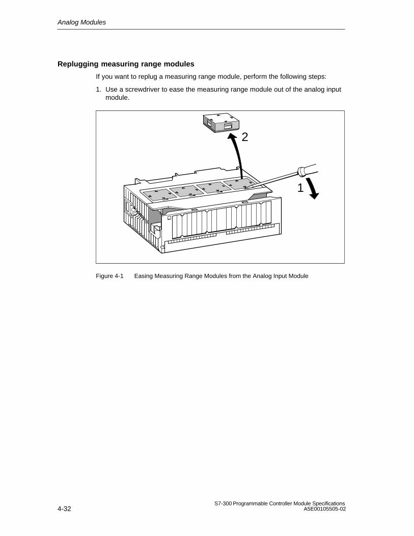
Analog Modules
4-32S7-300 Programmable Controller Module Specifications
A5E00105505-02
Replugging measuring range modules
If you want to replug a measuring range module, perform the following steps:
1. Use a screwdriver to ease the measuring range module out of the analog inputmodule.
1
2
Figure 4-1 Easing Measuring Range Modules from the Analog Input Module

Analog Modules
4-33S7-300 Programmable Controller Module SpecificationsA5E00105505-02
2. Insert the measuring range module (correctly positioned (1)) into the analoginput module.
The measuring range selected is the one that points to marker point onmodule (2).
1
2
Figure 4-2 Inserting Measuring Range Modules into the Analog Input Module
Perform the same steps for all other measuring range modules.
The next step is to install the module.
!Caution
If you have not set the measuring range modules correctly, the module may bedestroyed.
Make sure that the measuring range module is in the correct position beforeconnecting a sensor to the module.

Analog Modules
4-34S7-300 Programmable Controller Module Specifications
A5E00105505-02
4.5 Behavior of the Analog Modules
Introduction
In this section, you will find information on:
How the analog input and output values depend on the operating states of theCPU and the supply voltage of the analog module
The behavior of the analog modules depending on where the analog values liewithin the value range
The effect of the operational limit of the analog module on the analog input andoutput value, as illustrated by an example
4.5.1 Effect of Supply Voltage and Operating Mode
Effect of supply voltage and operating mode on the modules
The input and output values of the analog modules depend on the operating stateof the CPU and on the supply voltage of the module.

Analog Modules
4-35S7-300 Programmable Controller Module SpecificationsA5E00105505-02
Table 4-38 Dependencies of the Analog Input/Output Values on the Operating State of the CPU and theSupply Voltage L+
CPU OperatingState
Supply Vol-tage L+ at
Analog Mo-dule
Input Value of the Analog Input Module
Output Value of the Analog Output Module
POWER RUN L+ present Measured value CPU valuesON
7FFFH until first conversionfollowing power-up or afterparameter assignment of themodule has been completed
Until the first conversion...
after power-up has beencompleted, a signal of 0 mAor 0 V is output.
after parameterassignment has beencompleted, the previousvalue is output.
L+ missing Overflow value 0 mA/0 V
POWER STOP L+ present Measured value Substitute value/last valueON
7FFFH until first conversionfollowing power-up or afterparameter assignment of themodule has been completed
(default values: 0 mA/0 V)
L+ missing Overflow value 0 mA/0 V
POWER – L+ present – 0 mA/0 VOFF
L+ missing – 0 mA/0 V
Behavior on failure of the supply voltage
Failure of the supply voltage of the analog modules is always indicated by the SFLED on the module. Furthermore, this information is made available on the module(entry in diagnostic buffer).
Triggering of the diagnostic interrupt depends on the parameter assignment (seeSection 4.7).

Analog Modules
4-36S7-300 Programmable Controller Module Specifications
A5E00105505-02
4.5.2 Effect of Range of Values of the Analog Values
Effect of errors on analog modules with diagnostics capability
Any errors that occur can lead to a diagnostics entry and a diagnostic interrupt withanalog modules with diagnostics capability and corresponding parameterassignment. You will find the errors that might be involved in Section 4.16.
Effect of range of values on the analog input module
The behavior of the analog modules depends on where the input values lie withinthe range of values.
Table 4-39 Behavior of the Analog Input Modules as a Function of the Position of theAnalog Value within the Range of Values
Measured Va-lue In
Input Value SF LED Diagnostics Interrupt
Rated range Measuredvalue
– – –
Overrange/underrange
Measuredvalue
– – –
Overflow 7FFFH Flashes1 Entered1 Diagnosticinterrupt1
Underflow 8000H Flashes1 Entered1 Diagnosticinterrupt1
Beyond theprogrammedlimit
Measuredvalue
– – Hardware interrupt1
1) Only for modules with diagnostics capability and depending on parameter assignment

Analog Modules
4-37S7-300 Programmable Controller Module SpecificationsA5E00105505-02
Effect of range of values on the analog output module
The behavior of the analog modules depends on where the output values lie withinthe value range.
Table 4-40 Behavior of the Analog Output Modules as a Function of the Position of theAnalog Value within the Range of Values
Process ValueLies Within
Output Value SF LED Diagnostics Interrupt
Rated range CPU value – – –
Overrange/underrange
CPU value – – –
Overflow 0 signal – – –
Underflow 0 signal – – –

Analog Modules
4-38S7-300 Programmable Controller Module Specifications
A5E00105505-02
4.5.3 Effect of Operational Limit and Basic Error Limit
Operational limit
The operational limit is the measuring error or output error of the analog moduleover the entire temperature range authorized for the module, referred to the ratedrange of the module.
Basic error limit
The basic error limit is the operational limit at 25 °C, referred to the rated range ofthe module.
Note
The percentage details of operational and basic error limits in the technicalspecifications of the module always refer to the highest possible input and outputvalue in the rated range of the module.
Example of determination of the output error of a module
An analog output module SM 332; AO 4 12 bits is being used for voltage output.The output range from ”0 to 10 V” is being used. The module is operating at anambient temperature of 30 °C. Thus the operational limit applies. The technicalspecifications of the module state:
Operational limit for voltage output:0.5 %
An output error, therefore, of 0.05 V (0.5% of 10 V) over the whole rated rangeof the module must be expected.
This means that with an actual voltage of, say, 1 V, a value in the range from 0.95V to 1.05 V is output by the module. The relative error is 5 % in this case.
The figure below shows for the example how the relative error becomesincreasingly less the more the output value approximates to the end of the ratedrange of 10 V.
0.05 V
1 V0 V
0.05 V
Output value
0.05 V
8 V 10 V
* Operational limit
–1 V
( 0.5 %*)( 0.625 %)( 5 %)
Figure 4-3 Example of the Relative Error of an Analog Output Module

Analog Modules
4-39S7-300 Programmable Controller Module SpecificationsA5E00105505-02
4.6 Conversion, Cycle, Setting and Response Time of AnalogModules
Conversion time of analog input channels
The conversion time consists of a basic conversion time and additional processingtimes of the module for:
Resistance test
Wire-break monitoring
The basic conversion time depends directly on the conversion method of theanalog input channel (integrating method, instantaneous value conversion).
In the case of integrating conversion methods, the integration time has a directinfluence on the conversion time. The integration time depends on the interferencefrequency suppression that you set in STEP 7 (refer to Section 4.7.1).
For the basic conversion times and additional processing times of the differentanalog modules refer to the technical specifications of the module concerned,starting at Section 4.21.
Scan time of analog input channels
Analog-to-digital conversion and the transfer of the digitized measured values tothe memory and/or to the bus backplane are performed sequentially – in otherwords, the analog input channels are converted one after the other. The scan time– in other words, the time elapsing until an analog input value is again converted, isthe sum of the conversion times of all activated analog input channels of theanalog input module.
The following figure illustrates the components of the scan time for an n-channelanalog module.
Conversion time, channel 1Conversion time, channel 1
Conversion time, channel 2
Conversion time, channel n
Scan time
Figure 4-4 Scan Time of an Analog Input or Output Module

Analog Modules
4-40S7-300 Programmable Controller Module Specifications
A5E00105505-02
Conversion and scan times for analog input channels in channel groups
When the analog input channels are grouped in channel groups, you must take intoaccount the conversion time channel group by channel group.
Example
Two analog input channels channels of the analog input module SM 331; AI 212bits are combined to form a channel group. You must therefore grade the scantime in steps of 2.
Setting smoothing of analog values
You can set the smoothing of the analog values in STEP 7 for some analog inputmodules.
Using smoothing
Smoothing of analog values ensures a stable analog signal for further processing.
It makes sense to smooth the analog values with slow variations of measuredvalues – for example, with temperature measurements.
Smoothing principle
The measured values are smoothed by digital filtering. Smoothing is accomplishedby the module calculating average values from a defined number of converted(digitized) analog values.
The user assigns parameters to smoothing at not more than four levels (none, low,average, high). The level determines the number of analog signals used foraveraging.
The higher the smoothing level chosen, the more stable is the smoothed analogvalue and the longer it takes until the smoothed analog signal is applied after astep response (refer to the following example).

Analog Modules
4-41S7-300 Programmable Controller Module SpecificationsA5E00105505-02
Example
The following figure shows the number of module cycles for a step response afterwhich the smoothed analog value is approximately 100% applied, as a function ofthe smoothing that has been set. The figure applies to every change of signal atthe analog input.
50
100
0
63
50 100 150 200Smoothing: low:
average:high:
Module cycles
Signal variationin percent
Step response for any analog input signal
Figure 4-5 Example of the Influence of Smoothing on the Step Response
Additional information on smoothing
Refer to the specific section on the analog input module (from Section 4.21) todetermine whether smoothing can be set for the specific module and for anyspecial features that have to be taken into account.
Conversion time of the analog output channels
The conversion time of the analog output channels comprises the transfer of thedigitized output values from the internal memory and the digital-to-analogconversion.
Scan time of analog output channels
The analog output channels are converted sequentially – in other words, theanalog output channels are converted one after the other.
The scan time – in other words, the time elapsing until an analog output value isagain converted, is the sum of the conversion times of all activated analog outputchannels (refer to 4-4).

Analog Modules
4-42S7-300 Programmable Controller Module Specifications
A5E00105505-02
Tip
You should disable any analog channels that are not being used to reduce the scantime in STEP 7.
Overview of the settling time and response time of the analog output modules
tA
tZ
tE
t1 t2
tA = Response time
tZ = Scan time corresponds to n conversion time (n = activated channels)
tE = Settling time
t1 = New digitized output value is present
t2 = Output value transferred and converted
t3 = Specified output value reached
t3
Figure 4-6 Settling and Response times of the Analog Output Channels
Settling time
The settling time (t2 to t3) – in other words, the time elapsing from application theconverted value until the specified value is reached at the analog output – isload-dependent. A distinction is made between resistive, capacitive and inductiveloads.
For the settling times of the different analog output modules as a function of loadrefer to the technical specifications of the module concerned, starting atSection 4.27.
Response time
The response time (t1 to t3) – in other words, the time elapsing from application ofthe digital output values in the internal memory until the specified value is reachedat the analog output – in a worst case scenario is the sum of the scan time and thesettling time.
You have a worst case situation, if, shortly prior to the transfer of a new outputvalue, the analog channel has been converted and is not converted again until allother channels are converted (scan time).

Analog Modules
4-43S7-300 Programmable Controller Module SpecificationsA5E00105505-02
4.7 Analog Module Parameter Assignment
Introduction
Analog modules can have different characteristics. You can set the characteristicsof the modules by means of parameter assignment.
Tools for parameter assignment
You assign parameters to analog modules with STEP 7. You must performparameter assignment in STOP mode of the CPU.
When you have set all the parameters, download the parameters from theprogramming device to the CPU. On a transition from STOP to RUN mode, theCPU then transfers the parameters to the individual analog modules.
In addition, if necessary you must place the measuring range modules of themodule in the necessary position (refer to Section 4.4).
Static and dynamic parameters
The parameters are divided into static and dynamic parameters.
Set the static parameters in STOP mode of the CPU, as described above.
You can similarly modify the dynamic parameters in the current user program bymeans of SFCs. Note, however, that after a change from RUN STOP, STOP RUN of the CPU, the parameters set in STEP 7 apply again. You will find adescription of the parameter assignment of modules in the user program inAppendix A.
Parameter Settable with CPU OperatingState
Static PG (STEP7 HWCONFIG) STOP
Dynamic PG (STEP7 HWCONFIG) STOP
SFC 55 in the user program RUN

Analog Modules
4-44S7-300 Programmable Controller Module Specifications
A5E00105505-02
4.7.1 Parameters of the Analog Input Modules
The analog input modules use a subset of the parameters and ranges of valueslisted in the table below, depending on the functionality. Refer to the section on themodule concerned, starting from Section 4.21, for the subset ”mastered” by thespecific analog modules.
The default settings apply if you have not performed parameter assignment inSTEP 7.
Table 4-41 Parameters of the Analog Input Modules
Parameter Value Range DefaultSettings
Para-meterType
Scope
Enable Diagnostic interrupt Hardware interrupt
upon limit violation Hardware interrupt at
end of cycle
Yes/noYes/no
Yes/no
NoNo
No
Dynamic Module
Trigger for hardwareinterrupt
Upper limit value
Lower limit value
Constraint possible due to measuring range
32511 to –32512
–32512 to 32511
– DynamicChannel orChannelgroup
Diagnostics Group diagnostics
With wire-breakcheck
Yes/no
Yes/no
No
NoStatic
Channel orChannelgroup

Analog Modules
4-45S7-300 Programmable Controller Module SpecificationsA5E00105505-02
Table 4-41 Parameters of the Analog Input Modules, continued
Parameter ScopePara-meterType
DefaultSettings
Value Range
Measurement Measuring method Deactivated
U Voltage4DMU Current (4-wire transmitter)2DMU Current (2-wire transmitter)R-4L Resistance (four-conductor
connection)R-3L Resistance (three-conductor connection)RTD-4L Bulb resistor
(linear, four-conductor connection)
RTD-3L Bulb resistor(linear, three-conductor connection)
TC-I1) Thermocouple (internal comparison)
TC-E1) Thermocouple (external comparison)
TC-IL2) Thermocouple (linear, internal comparison)
TC-EL2) Thermocouple (linear, external
comparison)TC-L00C2) Thermocouple
(linear, reference temp. 0 °C)
TC-L50C2) Thermocouple (linear, reference temp. 50°C)
U
DynamicChannel orChannelgroup
Measuring range For the settable measuring ranges ofthe input channels, please refer to theindividual module description.
10 V
Reaction with openthermocouple
Overflow; underflow Overflow
Temperature unit3 Degrees Celsius; degrees Fahrenheit; degrees Kelvin
DegreesCelsius
Dynamic Module
Module filtering mode 8 channels hardware filter8 channels software filter4 channels hardware filter
8channels,hardwarefilter
Dynamic Module

Analog Modules
4-46S7-300 Programmable Controller Module Specifications
A5E00105505-02
Table 4-41 Parameters of the Analog Input Modules, continued
Parameter ScopePara-meterType
DefaultSettings
Value Range
Temperaturecoefficient fortemperaturemeasurement withbulb resistor (RTD)
Platinum (Pt)0.00385 / °C0.003916 / °C0.003902 / °C0.003920 / °C0.003851 / °CNickel (Ni)0.00618 / °C0.00672 / °CCopper (Cu)0.00427 / °C
0.00385 Dynamic Channel orchannelgroup
Interferencefrequencysuppression
400/60/50 Hz; 400 Hz; 60 Hz; 50 Hz;10 Hz
50 Hz Dynamic Channel orchannelgroup
Smoothing NoneLowAverageHigh
None Dynamic Channel orChannelgroup
1) The module supplies a decimal value of the measured thermal voltage to the CPU – for example, 27648 at 80 mV (refer to Table 4-11)
2) The module supplies a temperature value to the CPU – for example, 120°C (refer to Table 4-17)3) 1 digit =0.1 °C; 1 digit =0.1 °F

Analog Modules
4-47S7-300 Programmable Controller Module SpecificationsA5E00105505-02
4.7.2 Parameters of the Analog Output Modules
The analog output modules use a subset of the parameters and ranges of valueslisted in the table below, depending on the functionality. Refer to the section on themodule concerned, starting from Section 4.27, for the subset ”mastered” by thespecific analog modules.
The default settings apply if you have not performed parameter assignment inSTEP 7.
Table 4-42 Parameters of the Analog Output Modules
Parameter Value Range DefaultSettings
ParameterType
Scope
Enable Diagnostic
interruptYes/no No Dynamic Module
Diagnostics Group diagnostics Yes/no No Static Channel
Output Output type Deactivated
VoltageCurrent
U
Dynamic Channel
Output range For the settable measuring ranges of theoutput channels, please refer to theindividual module description.
10 V
Response withCPU-STOP
ASS Outputs de-energizedLWH Hold last valueEWS Apply substitute value
ASSDynamic Channel

Analog Modules
4-48S7-300 Programmable Controller Module Specifications
A5E00105505-02
4.7.3 Parameters of the Analog Input/Output Modules
The analog input/output modules make available the parameters in the followingtable. The default settings apply if you have not performed parameter assignmentin STEP 7.
Table 4-43 Parameters of the Analog Input/Output Modules
Parameter Value Range DefaultSettings
ParameterType
Scope
InputMeasurement Measuring
methodDeactivatedU VoltageR-4L Resistance (four-conductor
connection)RTD-4L Bulb resistor
(linear, four-conductor connection)
RTD-4L
Dynamic Channel
Measuring range 0 to 10 V10000 Pt 100 climate
Pt 100climate
Integration time 20 ms; 16.6 ms 20 ms
Output Output type Deactivated
VoltageU
Dynamic Channel
Output range 0 to 10 V 0 to 10 V

Analog Modules
4-49S7-300 Programmable Controller Module SpecificationsA5E00105505-02
4.8 Connecting Sensors to Analog Inputs
Introduction
You can connect different sensors to the analog input modules depending on themeasuring method; voltage and current sensors, and resistors.
This section contains general information that is generally applicable to all theconnection options for sensors described in the sections that follow.
Cables for analog signals
To reduce electrical interference, you should use twisted-pair shielded cables forthe analog signals. The shield of the analog signal cables should be grounded atboth cable ends.
If there are potential differences between the cable ends, an equipotential bondingcurrent can flow over the shield, which leads to an interference of the analogsignals. In such a case, you should ground the shield at one end of the cable only.
Isolated analog input modules
With the isolated analog input modules there is no electrical connection betweenthe reference point of the measuring circuit MANA and the M terminal of the CPU.
You must use isolated analog input modules if a potential difference UISO canoccur between the reference point of the measuring circuit MANA and theM terminal of the CPU. By means of a equipotential bonding conductor betweenthe MANA terminal and the M terminal of the CPU, make sure that UISO does notexceed the permitted value.
Non-isolated analog input modules
With the non-isolated analog input modules, you must establish a connectionbetween the reference point of the measuring circuit MANA and the M terminal ofthe CPU. Establish IM 153. For this purpose, connect the MANA terminal with the Mterminal of the CPU and IM 153. A potential difference between MANA and the Mterminal of the CPU and the IM 153 can result in corruption of the analog signal.
Limited potential difference UCM
Only a limited potential difference UCM (common mode voltage) may occurbetween the measuring lines M– of the input channels and the reference point ofthe measuring circuit MANA. In order to prevent the permissible value from beingexceeded, you must take different actions, described below, depending on thepotential connection of the sensors.

Analog Modules
4-50S7-300 Programmable Controller Module Specifications
A5E00105505-02
Abbreviations and mnemonics used in the figures below
The abbreviations and mnemonics used in the figures below have the followingmeanings:
M +: Measuring lead (positive)
M–: Measuring lead (negative)
MANA: Reference potential of the analog measuring circuit
M: Ground terminal
L +: Terminal for 24 VDC supply voltage
UCM: Potential difference between inputs and reference potential of the MANA measuring circuit
UISO: Potential difference between MANA and M terminal of CPU
Connecting isolated measuring sensors
Isolated sensors are not connected with the local ground potential (local ground).They can be operated free of potential.
With isolated sensors, potential differences might arise between the differentsensors. These potential differences can arise as a result of interference or thelocal distribution of the sensors.
To prevent the permissible value for UCM being exceeded when they are used inenvironments with a high level of EMC interference, we advise you to link M– withMANA.

Analog Modules
4-51S7-300 Programmable Controller Module SpecificationsA5E00105505-02
You can operate the CPU in Grounded mode (refer to the figure below) orUngrounded mode.
Isolated sensors
M+
M
L+
M–
MANA
M+M– Backplane
bus
ADC
MinternalL+M
Ground bus
CPU
UISO
Logi
c
Recommended connection
Figure 4-7 Connecting Isolated Sensors to an Isolated AI
Isolated sensors
M+
M
L+
M–
MANA
M+M– Backplane
bus
MinternalL+M
Ground bus
CPU
ADC Logic
Recommended connection
Figure 4-8 Connecting Isolated Sensors to a Non-Isolated AI

Analog Modules
4-52S7-300 Programmable Controller Module Specifications
A5E00105505-02
Note
Do not connect M– to MANA when connecting 2-wire transmitters for currentmeasurement and resistance-type sensors. This also applies to inputs which arenot used.
Non-isolated sensors
The non-isolated sensors are connected with the local ground potential (localground). When using non-isolated sensors, you must connect MANA to the localground.
Connecting non-isolated sensors
Caused by local conditions or interferences potential differences UCM (static ordynamic) can occur between the locally distributed individual measuring points. Ifthe potential difference UCM exceeds the permissible value, you must provideequipotential bonding conductors between the measuring points.
When connecting non-isolated sensors to optically isolated modules, you canoperate the CPU in Grounded mode (refer to the figure below) or Ungroundedmode.
Non-isolatedsensors
M+
M
L+
M–
MANA
M+M– Backplane
bus
UCM
ADC
MinternalL+M
Ground bus
CPUUISO
Equipotentialbondingconductor
Logi
c
Figure 4-9 Connecting Non-Isolated Sensors to an Isolated AI
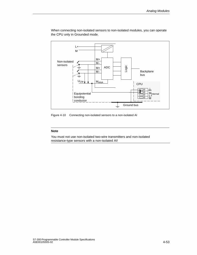
Analog Modules
4-53S7-300 Programmable Controller Module SpecificationsA5E00105505-02
When connecting non-isolated sensors to non-isolated modules, you can operatethe CPU only in Grounded mode.
Non-isolatedsensors
M+
M
L+
M–
MANA
M+M– Backplane
bus
MinternalL+M
Ground bus
CPU
ADC
UCM
Equipotentialbondingconductor
Logi
c
Figure 4-10 Connecting non-isolated sensors to a non-isolated AI
Note
You must not use non-isolated two-wire transmitters and non-isolatedresistance-type sensors with a non-isolated AI!

Analog Modules
4-54S7-300 Programmable Controller Module Specifications
A5E00105505-02
4.9 Connecting Voltage Sensors
Note
The necessary connecting cables, which result from the potential connection of theanalog input module and the sensors, are not drawn in the figures shown below.
In other words, you must continue to take note of and implement Section 4.8 withits generally valid information for connecting sensors.
Abbreviations and mnemonics used in the figure below
The abbreviations and mnemonics used in the figure below have the followingmeanings:
M +: Measuring lead (positive)
M–: Measuring lead (negative)
MANA: Reference potential of the analog measuring circuit
M : Ground terminal
L +: Terminal for 24 VDC supply voltage
Connection of voltage sensors
M+
M
L+
M–
MANA
M+
M–ADC
+
–U
+
–U Backplane busLo
gic
Figure 4-11 Connecting Voltage Sensors to an Isolated AI

Analog Modules
4-55S7-300 Programmable Controller Module SpecificationsA5E00105505-02
4.10 Connecting Current Sensors
Note
The necessary connecting cables, which result from the potential connection of theanalog input module and the sensors, are not drawn in the figures shown below.
In other words, you must continue to take note of and implement Section 4.8 withits generally valid information for connecting sensors.
Abbreviations and mnemonics used in the figures below
The abbreviations and mnemonics used in the figures below have the followingmeanings:
M +: Measuring lead (positive)
M–: Measuring lead (negative)
MANA: Reference potential of the analog measuring circuit
M : Ground terminal
L +: Terminal for 24 VDC supply voltage
Supply voltage of the sensors
The 2-wire transmitter receives its short-circuit-proof power supply via theterminals of the analog input module.
This transmitter then converts the measured variable into a current. Two-wiretransmitters must be isolated sensors.
Four-wire transmitters have separate power supplies.

Analog Modules
4-56S7-300 Programmable Controller Module Specifications
A5E00105505-02
Connecting 2-wire transmitters
M+
ML+
M–
MANA
M+
M–
ADCTwo-wiretransmitter
Two-wiretransmitterP
P
+–
+–
Sensor, for example,pressure gauge
Backplanebus
Logi
c
Figure 4-12 Connecting Two-Wire Transmitters to an Isolated AI
When the supply voltage L+ is fed from the module, you must assign parametersto the two-wire transmitter as a four-wire transmitter in STEP 7.
ML+
MANA
M+
M–
ADC
Two-wire transmitter
–
Backplanebus
+P
Sensor, for example,pressure gauge
Logi
c
Figure 4-13 Connecting Two-Wire Transmitters Supplied from L+ to an Isolated AI

Analog Modules
4-57S7-300 Programmable Controller Module SpecificationsA5E00105505-02
Connecting four-wire transmitters
M+
M
L+
M–
MANA
M+
M–
ADCP
P
Sensor, for example,pressure gauge
tran
smitt
erF
our-
wire
+–
+–
L+ M
Backplanebus
Logi
c
Figure 4-14 Connecting Four-Wire Transmitters to an Isolated AI
4.11 Connecting Resistance Thermometers and Resistors
Note
The necessary connecting cables, which result from the potential connection of theanalog input module and the sensors, are not drawn in the figures shown below.
In other words, you must continue to take note of and implement Section 4.8 withits generally valid information for connecting sensors.
Abbreviations and mnemonics used in the figures below
The abbreviations and mnemonics used in the figures below have the followingmeanings:
IC+: Constant-current lead (positive)
IC–: Constant-current lead (negative)
M+: Measuring lead (positive)
M–: Measuring lead (negative)
MANA: Reference potential of the analog measuring circuit
M: Ground terminal
L+: Terminal for 24 VDC supply voltage
S–: Detector lead (negative)

Analog Modules
4-58S7-300 Programmable Controller Module Specifications
A5E00105505-02
Connecting resistance thermometers and resistors
The resistance thermometers/resistors are wired in a four-conductor,three-conductor or two-conductor connection.
With four-conductor and three-conductor connections, the module supplies aconstant current via terminals IC+ and IC– so that the potential drop occurring onthe measuring cables is compensated. It is important that the connected constantcurrent cables are directly connected to the resistance thermometer/resistor.
Measurements with four-conductor or three-conductor connections supply a moreprecise measuring result due to compensation than measurements with atwo-conductor connection.
Four-conductor connection of a resistance thermometer
The voltage generated at the resistance thermometer is measured via the M+ andM– terminals. When you connect, watch out for the polarity of the connected cable(connect IC+ and M+ as well as IC– and M– to the resistance thermometer).
When connecting, make sure that the connected cables IC+ and M+ and thecables IC– and M– are connected directly to the resistance thermometer.
M+
M
L+
M–
MANA
ADCIC+
IC–IC
Backplanebus
Logi
c
Figure 4-15 Four-conductor connection of resistance thermometers to an isolated AI

Analog Modules
4-59S7-300 Programmable Controller Module SpecificationsA5E00105505-02
Three-conductor connection of a resistance thermometer
With a three-conductor connection on modules with four terminals, you mustnormally insert a jumper between M– and IC– (refer to Figure 4-16). Take note ofthe exception for the SM 331; AI 8 RTD (refer to Figure 4-18).
When connecting, make sure that the connected cables IC+ and M+ areconnected directly to the resistance thermometer.
M+
M
L+
M–
MANA
ADCIC+
IC–IC
Backplanebus
Logi
c
Figure 4-16 Three-Conductor Connection of Resistance Thermometers to an Isolated AI
Two-conductor connection of a resistance thermometer
With a two-conductor connection, you must insert jumpers on the module betweenM+ and IC+ and between M– and IC– .
M+
M
L+
M–
MANA
ADCIC+
IC–
BackplanebusLo
gic
Figure 4-17 Two-Conductor Connection of Resistance Thermometers to an Isolated AI

Analog Modules
4-60S7-300 Programmable Controller Module Specifications
A5E00105505-02
Three-conductor connection to the SM 331; AI 8 RTD
With a three-conductor connection to the SM 331; AI 8 RTD you must insert ajumper between M+ and IC+ (refer to figure4-18).
When connecting, make sure that the connected cables IC– and M– are connecteddirectly to the resistance thermometer.
M+
M
L+
M–
MANA
ADCIC+
IC–IC
Backplanebus
Logi
c
Figure 4-18 Three-Conductor Connection of Resistance Thermometers to the SM 331; AI 8 RTD
!Caution
Due to incorrect wiring of the three-conductor connection, unforeseen operation ofthe module and dangerous conditions can result in the system.

Analog Modules
4-61S7-300 Programmable Controller Module SpecificationsA5E00105505-02
4.11.1 Connecting Resistance Thermometers to the SM 331; AI 8 13 bits
Two-conductor connection
With a two-conductor connection, you must insert jumpers on the module betweenM– and S–.
Backplanebus
M+
M–
ADC
S–
Logi
c
Figure 4-19 Two-Conductor Connection of Resistance Thermometers to the SM 331; AI 813 bits
Three-conductor connection
M+
M–
ADC
S–
Backplanebus
Logi
c
Figure 4-20 Three-Conductor Connection of Resistance Thermometers to the SM 331; AI 8 13 bits
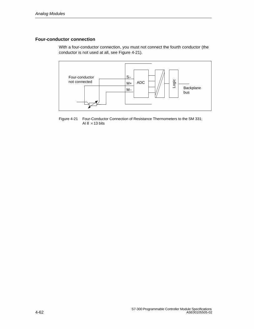
Analog Modules
4-62S7-300 Programmable Controller Module Specifications
A5E00105505-02
Four-conductor connection
With a four-conductor connection, you must not connect the fourth conductor (theconductor is not used at all, see Figure 4-21).
Backplanebus
Four-conductornot connected M+
M–
ADC
S–
Logi
c
Figure 4-21 Four-Conductor Connection of Resistance Thermometers to the SM 331; AI 8 13 bits

Analog Modules
4-63S7-300 Programmable Controller Module SpecificationsA5E00105505-02
4.12 Connecting Thermocouples
Design of thermocouples
A thermocouple consists of a pair of sensors and the necessary installation andconnecting parts. The thermocouple consists of two wires of dissimilar metals ormetal alloys soldered or welded together at the ends.
There are different types of thermocouple, depending on the composition of thematerial used – for example, K, J, N thermocouples. The measuring principle of allthermocouples is the same, irrespective of their type.
° C
Leads
Compensating leads
Reference junction
Connecting point
Thermocouple with positive or negative limbs
Measuring junction
Point at which thermo-e. m. f. is measured
Figure 4-22 Design of Thermocouples
Principle of operation of thermocouples
If the measuring point is subjected to a temperature different from that of the freeends of the thermocouple (point of connection), a voltage, the thermo emf, occursat the free ends. The magnitude of the thermo-e.m.f. generated depends on thedifference between the temperature at the measuring junction and the temperatureat the free ends, as well as on the material combination used for the thermocouple.
Since a thermocouple always measures a temperature difference, the free endsmust be kept at a known temperature at a reference junction in order to determinethe temperature of the measuring junction.
The thermocouples can be extended from their point of connection to the referencejunction by means of compensating wires. These compensating wires consist ofthe same material as the thermocouple wires. The supply leads are copper wire.Note: Make sure these wires are connected with the correct polarity, otherwisethere will be considerable measuring errors.

Analog Modules
4-64S7-300 Programmable Controller Module Specifications
A5E00105505-02
Compensation of the reference junction temperature
You can compensate for the effects of temperature fluctuations at the referencejunction by means of compensating leads.
There are several options for you to choose from for acquiring the referencejunction temperature in order to obtain an absolute temperature value from thedifference in temperature between the reference junction and measuring point.
You can use internal or external compensation, depending on where you want thereference junction to be.
Table 4-44 Options for Compensation of the Reference Junction Temperature
Option Explanation
No compensation If you want to acquire only the difference in temperaturebetween the measuring point and the reference junction.
Internal compensation(refer to Figure 4-23 for connection)
If you employ internal compensation, the internaltemperature (thermocouple internal comparison) of themodule is used for comparison purposes.
External compensation with compensatingbox in the leads of an individualthermocouple (refer to Figures 4-24 and4-25 for its connection)
You have already acquired and compensated thereference junction temperature (thermocouple externalcomparison) using a compensating box, which you havelooped into an individual thermocouple.
No further processing is necessary owing to the module.
Only for SM 331; AI 8 TC:
External compensation with resistancethermometer for acquisition of the referencejunction temperature(refer to Figure 4-26 and 4-27 forconnection)
You can acquire the reference temperature by means of aresistance thermometer (platinum or nickel) and have itcalculated by the module for any thermocouple.
Theory of operation of internal compensation
With internal compensation, you can establish the reference point across theterminals of the analog input modules. In this case, you must run thecompensating lines right up to the analog module. The internal temperature sensoracquires the temperature of the module and supplies a compensation voltage.
Note that internal compensation is not as accurate as external compensation.

Analog Modules
4-65S7-300 Programmable Controller Module SpecificationsA5E00105505-02
Theory of operation of external compensation with compensating box
If you employ external compensation, the temperature of the reference junction ofthe thermocouples is taken into account via a compensating box, for example.
The compensating box contains a bridge circuit calibrated for a definite referencejunction temperature. The reference junction is formed by the connections for theends of the thermocouple’s compensating leads.
If the actual temperature deviates from the compensating temperature, thetemperature-sensitive bridge resistance changes. This results in a positive ornegative compensating voltage, which is added to the thermo-e.m.f.
Abbreviations and mnemonics used in the figures below
The abbreviations and mnemonics used in the figures below have the followingmeanings:
M +: Measuring lead (positive)
M–: Measuring lead (negative)
IC+: Positive connection of constant current output
IC-: Negative connection of constant current output
COMP+: Compensating terminal (positive)
COMP –: Compensating terminal (negative)
MANA: Reference potential of the analog measuring circuit
M : Ground terminal
L +: Terminal for 24 VDC supply voltage
P5V: Module logic power supply
Note
The necessary connecting cables, which result from the potential connection of theanalog input module and the sensors, are not drawn in the figures shown below.
In other words, you must continue to take note of and implement Section 4.8 withits generally valid information for connecting sensors.

Analog Modules
4-66S7-300 Programmable Controller Module Specifications
A5E00105505-02
Connection of thermocouples with internal compensation
Connect the thermocouples to the inputs of the module, either directly or by meansof compensating lines. Each channel group can use a thermocouple typesupported by the analog module independently of the other channel groups.
M+M–
M+M–
ADC
M
L+
COMP–/MANA
COMP+Compensating leads(same material asthermocouple)
Backplanebus
K7
K0
.
.
.
Thermocouple
Logi
c
Figure 4-23 Connection of Thermocouples with Internal Compensation to an Isolated AI
Connecting the compensating box
Connect the compensating box to the COMP terminals of the module, locating thecompensating box at the reference junction of the thermocouples. Thecompensating box must have an isolated supply. The power supply must haveadequate filtering, for example by means of a grounded shielding winding.
The terminals for connecting the thermocouple to the compensating box are notrequired and must therefore be shorted (refer to Figure 4-25 for an example).
The following constraints apply:
The parameters of a channel group are general valid for all channels of thatgroup (for example, input voltage, integrating time etc.)
External compensation with connection of the compensating box to the COMPterminals of the module can be performed only for one thermocouple type. Inother words, all channels operating with external compensation must use thesame type.

Analog Modules
4-67S7-300 Programmable Controller Module SpecificationsA5E00105505-02
Connecting thermocouples with compensating box
If all thermocouples connected to the inputs of the module have the samecomparison point, you compensate as follows:
M+M–
M+M– Backplane
bus
ADC
M
L+
Compensatingleads (samematerial asthermocouple) Box
Comp.
Ref. junction
ML+
Copperwire
COMP–/MANA
COMP+
Thermocouples
Logi
c
Figure 4-24 Connection of Thermocouples with Compensation Box to an Isolated AI
Note
Use compensating boxes with a reference junction temperature of 0C foranalog input modules.
Recommended compensating box
We recommend you to use a comparison point (with integrated power supply unit)from Siemens as a compensating box. You will find the necessary ordering data inthe table below.

Analog Modules
4-68S7-300 Programmable Controller Module Specifications
A5E00105505-02
Table 4-45 Ordering Data of the Comparison Point
Recommended Compensating Box Order number
Reference junction with integrated power supplyunit, for rail mounting
Auxiliary power 220 VAC
110 VAC
24 VAC
24 VDC
Connection to thermocouple Fe-CuNi Type L
Fe/Cu Ni Type J
Ni Cr/Ni Type K
Pt 10% Rh/Pt Type S
Pt 13% Rh/Pt Type R
Cu/Cu Ni Type U
Cu/Cu Ni Type T
Reference temperature 0C
M72166-
B1
B2
B3
B4
1
2
3
4
5
6
7
00

Analog Modules
4-69S7-300 Programmable Controller Module SpecificationsA5E00105505-02
Connecting to the comparison point (Order No. M72166-xxx00)
If all thermocouples connected to the inputs of the module have the samecomparison point, you compensate as follows:
M+M–
M+M– Back-
planebus
ADC
M
L+Compensating leads(same material asthermocouple)
Copperwire
COMP–/MANA
COMP+
Thermocouples
13
Auxiliary power+ –
The terminals for thecompensating wire mustbe short-circuited!
Output (Cu wires)
89
1112
–+
SIEMENS
M72166-
Logi
c
Figure 4-25 Connection of Thermocouples with Comparison Point (Order No. M72166-xxx00) to anIsolated AI

Analog Modules
4-70S7-300 Programmable Controller Module Specifications
A5E00105505-02
Connecting thermocouples with temperature compensation to the SM 331; AI 8 × TC
All 8 inputs are available as measurement channels when the thermocouples areconnected via reference junctions that are controlled at 0 °C or 50 °C.
Backplane busADUs
L+
M
K7
K0M+M-
M+M-
M+M-
Copper wire
Reference junctioncontrolled at0C or 50C
K6
.
.
.
Figure 4-26 Connecting Thermocouples via a Reference Junction to the SM 331; AI 8 × TC

Analog Modules
4-71S7-300 Programmable Controller Module SpecificationsA5E00105505-02
Connecting thermocouples with resistance thermometer to the SM 331; AI 8 × TC
With this type of compensation, the reference junction terminal temperature isdetermined by a bulb resistor sensor with a temperature range of -25 °C to 85 °C.
Back-planebus
ADC
M
L+
Compensatingleads (samematerial asthermocouple)
Ref. junction
Copper wire
M–
M+
Thermocouples
IC+
IC–
Pt 100
M+M–
M+M–
K0
K7
P5V
M internal
Logi
c
Figure 4-27 Connecting Thermocouples with External Compensation via Resistance Thermometers tothe SM 331; AI 8 × TC

Analog Modules
4-72S7-300 Programmable Controller Module Specifications
A5E00105505-02
4.13 Connecting Loads/Actuators to Analog Output
Introduction
You can use the analog output modules to supply loads and actuators with currentand voltage.
This section contains general information that is generally applicable to all theconnection options for loads and actuators described in the sections that follow.
Cables for analog signals
For the analog signals, you should use shielded and twisted pair cables. The cablesQV and S+ and M and S–, respectively, are to be twisted together. This reduces theinterference. Ground the screen of the analog cables at both ends of the cables.
If there are potential differences between the cable ends, an equipotential bondingcurrent, which can flow over the shield, can cause interference of the analogsignals. In such a case, you should ground the shield at one end of the cable only.
Isolated analog output modules
With the isolated analog output modules there is no electrical connection betweenthe reference point of the measuring circuit MANA and the M terminal of the CPU.
You must use isolated analog output modules if a potential difference UISO canoccur between the reference point of the measuring circuit MANA and theM terminal of the CPU. By means of a equipotential bonding conductor betweenthe MANA terminal and the M terminal of the CPU, make sure that UISO does notexceed the permitted value.
Non-isolated analog output modules
With the non-isolated analog output modules, you must establish a connectionbetween the reference point of the measuring circuit MANA and the M terminal ofthe CPU. Therefore, connect the MANA terminal with the M terminal of the CPU. Apotential difference between MANA and the M terminal of the CPU can lead to acorruption of the analog signal.

Analog Modules
4-73S7-300 Programmable Controller Module SpecificationsA5E00105505-02
4.14 Connecting Loads and Actuators to Voltage Outputs
Connecting loads to a voltage output
Connecting loads to a voltage output is possible both in a four-conductor and atwo-conductor connection. However, not all analog output modules allow bothtypes of connection.
Note
The necessary connecting cables, which result from the potential connection of theanalog output module, are not drawn in the figures shown below.
In other words, you must continue to take note of and implement Section 4.13 withits generally valid information for connecting loads and actuators.
Abbreviations and mnemonics used in the figures below
The abbreviations and mnemonics used in the figures below have the followingmeanings:
QV: Analog output voltage
S +: Detector lead (positive)
S–: Detector lead (negative)
MANA: Reference potential of analog circuit
RL: Load impedance
L +: Terminal for 24 VDC supply voltage
M : Ground terminal
UISO: Potential difference between MANA and M terminal of CPU.

Analog Modules
4-74S7-300 Programmable Controller Module Specifications
A5E00105505-02
Connecting loads to a voltage output of an isolated module over afour-conductor connection
A high accuracy at the load can be achieved through the four-conductorconnection. You must therefore connect the sensor leads (S– and S+) directly tothe load. The voltage is thus measured and corrected directly at the load.
Interferences or a voltage drop can result in a potential difference between thesensor lead S– and the reference circuit of the analog circuit MANA. This potentialdifference must not exceed the permissible value. If the permissible potentialdifference is exceeded, the accuracy of the analog signal is impaired.
M
L+
DAC
RL
QV
MANA
MinternalL+M
Ground bus
CPU
S+
S–
UISO
Backplanebus
Logi
c
Figure 4-28 Connecting Loads to a Voltage Output of an Isolated AO over a Four-Conductor Connection

Analog Modules
4-75S7-300 Programmable Controller Module SpecificationsA5E00105505-02
Connecting loads to a voltage output of a non-isolated module over atwo-conductor connection
With a two-conductor connection, the S+ and S– terminals can be left open.However, you will not achieve the accuracy of a four-conductor connection.
Connect the load to terminals QV and the reference point of the measuring circuit,MANA.
M
L+
Backplane busDAC
MinternalL+M
Ground bus
CPU
RL
QV
MANA
Logi
c
Figure 4-29 Connecting Loads to a Voltage Output of a Non-Isolated AO over a Two-ConductorConnection

Analog Modules
4-76S7-300 Programmable Controller Module Specifications
A5E00105505-02
4.15 Connecting Loads and Actuators to Current Outputs
Note
The necessary connecting cables, which result from the potential connection of theanalog output module, are not drawn in the figures shown below.
In other words, you must continue to take note of and implement Section 4.13 withits generally valid information for connecting loads and actuators.
Abbreviations and mnemonics used in the figures below
The abbreviations and mnemonics used in the figures below have the followingmeanings:
QI: Analog output current
MANA: Reference potential of analog circuit
RL: Load impedance
L +: Terminal for 24 VDC supply voltage
M : Ground terminal
UISO: Potential difference between MANA and M terminal of CPU.
Connecting loads to a current output
You must connect loads to QI and the reference point of the analog circuit MANA ofa current output.
M
L+
Backplane busDAC
RL
QI
MANA
MinternalL+M
Ground bus
CPUUISO
Logi
c
Figure 4-30 Connecting Loads to a Current Output of an Isolated AO

Analog Modules
4-77S7-300 Programmable Controller Module SpecificationsA5E00105505-02
M
L+
Backplane busDAC
RL
QI
MANA
MinternalL+M
Ground bus
CPU
Logi
cFigure 4-31 Connecting Loads to a Current Output of a Non-Isolated AO
4.16 Diagnostics of the Analog Modules
Programmable and non-programmable diagnostic messages
In diagnostics, we make a distinction between programmable andnon-programmable diagnostic messages.
You obtain programmable diagnostic messages only if you have enableddiagnostics by parameter assignment. You perform parameter assignment in the”Diagnostics” parameter field in STEP 7 (refer to Section 4.7).
Non-programmable diagnostic messages are always made available by the analogmodule irrespective of diagnostics being enabled.
Actions following diagnostic message in STEP 7
Each diagnostic message leads to the following actions:
The diagnostic message is entered in the diagnosis of the analog module andforwarded to the CPU.
The error LED on the analog module lights.
If you have programmed ”Enable Diagnostic Interrupt” with STEP 7, adiagnostic interrupt is triggered and OB 82 is called (refer to Section 4.17).

Analog Modules
4-78S7-300 Programmable Controller Module Specifications
A5E00105505-02
Reading out diagnostic messages
You can read out detailed diagnostic messages by means of SFCs in the userprogram (refer to the Appendix ”Diagnostic Data of Signal Modules”).
You can view the cause of the error in STEP 7, in the module diagnosis (refer toonline Help for STEP 7).
Diagnostic message in the measured value of analog input modules
Every analog input module supplies the measured value 7FFFH irrespective of theparameter assignment when an error is detected. This measured value meanseither Overflow, Malfunction or a channel is disabled.
Diagnostic message by means of SF LED
Every analog module indicates errors for you by means of your SF LED (grouperror LED). The SF LED lights as soon as a diagnostic message is triggered by theanalog module. It goes out when all errors have been rectified.
Diagnostic messages of the analog input modules
The table below gives an overview of the diagnostic messages for the analog inputmodules.
Table 4-46 Diagnostic Messages of the Analog Input Modules
Diagnostics Message LED Diagnostics Ef-fective for
Parameters canbe Assigned
External auxiliary supply missing SF Module No
Configuring/parameter assignmenterror
SFChannel Yes
Common-mode error SF Channel Yes
Wire-break SF Channel Yes
Underflow SF Channel Yes
Overflow SF Channel Yes

Analog Modules
4-79S7-300 Programmable Controller Module SpecificationsA5E00105505-02
Diagnostic messages of the analog output modules
The table below gives an overview of the diagnostic messages for the analogoutput modules.
Table 4-47 Diagnostics Messages of the Analog Output Modules
Diagnostics Message LED DiagnosticsEffective for
Parameters canbe Assigned
External auxiliary supply missing SF Module No
Configuring/parameter assignmenterror
SFChannel Yes
Short-circuit to M SF Channel Yes
Wire-break SF Channel Yes
Note
A prerequisite for detecting the errors indicated by programmable diagnosticmessages is that you have assigned parameters to the analog module accordinglyin STEP 7.
Causes of errors and remedial measures for analog input modules
Table 4-48 Diagnostics Messages of the Analog Input Modules, Causes of Errors and RemedialMeasures
DiagnosticsMessage
Possible Error Cause Remedy
External load voltagemissing
Load voltage L+ of module missing Feed supply L+
Configuring/parameter Illegal parameters transferred to Check measuring range moduleassignment error module
Reassign module parameter
Common-mode error Potential difference UCM betweenthe inputs (M–) and referencepotential of measuring circuit (MANA)too high
Connect M– with MANA
Wire-break Resistance too high in the sensorconnection
Use different type of sensor orconnection, e.g. use conductors with alarger cross-sectional core area
Open circuit between module andsensor
Close circuit
Channel not connected (open) Disable channel group (”measuringprocedure” parameter
Connect channel

Analog Modules
4-80S7-300 Programmable Controller Module Specifications
A5E00105505-02
Table 4-48 Diagnostics Messages of the Analog Input Modules, Causes of Errors and RemedialMeasures
DiagnosticsMessage
RemedyPossible Error Cause
Underflow Input value underflows underrange,error may be caused:
Wrong measuring range selectedConfigure other measuring range
With the measuring ranges 4 to20 mA and 1 to 5 V, if necessary bypolarity reversal of sensorconnection
Check terminals
Overflow Input value overflows overrange Configure other measuring range
Causes of errors and remedial measures for analog output modules
Table 4-49 Diagnostics Messages of the Analog Output Modules, Causes of Errors and Remedial Measures
DiagnosticsMessage
Possible Error Cause Remedy
External load voltagemissing
Load voltage L+ of modulemissing
Feed supply L+
Configuring/parameterassignment error
Illegal parameters transferred tomodule
Reassign module parameter
Short-circuit after M Overload of output Eliminate overload
Short-circuit of output QV afterMANA
Eliminate short circuit
Wire-break Actuator resistance too high Use different type of actuator or connection,e.g. use conductors with a largercross-sectional core area
Open circuit between moduleand actuator
Close circuit
Channel not used (open) Disable channel group (”output type”parameter)

Analog Modules
4-81S7-300 Programmable Controller Module SpecificationsA5E00105505-02
4.17 Interrupts of the Analog Modules
Introduction
In this Section, the interrupt behavior of the analog modules is described. Thefollowing interrupts exist:
Diagnostic interrupt
Hardware interrupt
Note that not all analog modules have interrupt capability or they are only capableof a subset of the interrupts described here Refer to the technical specifications ofthe modules, starting at Section 4.21, to determine which analog modules haveinterrupt capability.
The OBs and SFCs mentioned below can be found in the online Help for STEP 7,where they are described in greater detail.
Enabling interrupts
The interrupts are not preset – in other words, they are inhibited withoutappropriate parameter assignment. Assign parameters to the Interrupt Enable inSTEP 7 (refer to Section 4.7).
Diagnostic interrupt
If you have enabled diagnostic interrupts, then active error events (initialoccurrence of the error) and departing error events (message aftertroubleshooting) are reported by means of an interrupt.
The CPU interrupts the execution of the user program and processes thediagnostic interrupt block (OB 82).
In the user program, you can call SFC 51 or SFC 59 in OB 82 to obtain moredetailed diagnostic information from the module.
The diagnostic information is consistent until such time as OB 82 is exited. WhenOB 82 is exited, the diagnostic interrupt is acknowledged on the module.

Analog Modules
4-82S7-300 Programmable Controller Module Specifications
A5E00105505-02
Hardware interrupt with trigger ”Upper or lower limit exceeded”
Define a working range by setting parameters for an upper and lower limit value. Ifthe process signal (for example, the temperature) leaves this working range, themodule triggers a hardware interrupt, provided the interrupt is enabled.
The CPU interrupts execution of the user program and processes the hardwareinterrupt block (OB 40).
In the user program of OB 40, you can set how the programmable logic controlleris required to react to a limit value being surpassed or not being reached.
When OB 40 is exited, the hardware interrupt is acknowledged on the module.
Note
Note that a hardware interrupt is not triggered if you have set the upper limit abovethe overrange or the lower limit below the underrange.
Structure of the start information tag OB40_POINT_ADDR of OB 40
The limit values exceeded by the different channels are entered in the startinformation of OB 40 in the tag OB40_POINT_ADDR. The following figure showsthe assignment to the bits of local data double word 8.
116 Bit no.1731 30 29 28 27 26
LD 81
LB 8 LB 9
25 24
Value exceeds upper limit in channel 0
Value falls below lower limit in channel 0
Value exceeds upper limit in channel 1
LB 11
01
Value falls below lower limit in channel 1
1 1
.0.1
Figure 4-32 Start Information of OB 40: Which Event Has Triggered the Hardware Interrupt at the LimitValue

Analog Modules
4-83S7-300 Programmable Controller Module SpecificationsA5E00105505-02
Hardware interrupt upon trigger ”Reached end of scan cycle”
By parameterizing the hardware interrupt a the end of the scan cycle, you have theoption of synchronizing a process with the scan cycle of the analog input module.
A scan cycle includes the conversion of the measured values of all enabledchannels of the analog input module. The module processes the channels oneafter the other. After all the measured values have been converted, the module ofthe CPU reports by means of an interrupt that there are new measured values onall channels.
You can use the interrupt to load the currently converted analog values.
4.18 Analog Input Module SM 331; AI 816 bits;(6ES7 331-7NF00-0AB0)
Order number
6ES7 331-7NF00-0AB0
Characteristics
The analog input module SM 331; AI 8 16 bits has the following characteristicfeatures:
8 inputs in 4 channel groups
Measured-value resolution 15 bits + sign (independent of integration time)
Measurement mode selectable per channel group:
– Voltage
– Current
Arbitrary measuring range and filter/update rate selection per channel group
Programmable diagnostics
Programmable diagnostic interrupt
Two channels with limit monitoring
Programmable hardware interrupt when limit has been exceeded
Isolated against the backplane bus interface
Permissible common mode voltage between channels of 50 VDC maximum
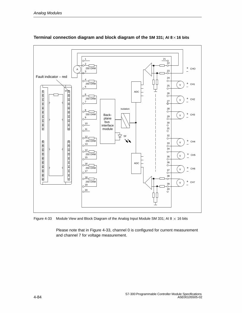
Analog Modules
4-84S7-300 Programmable Controller Module Specifications
A5E00105505-02
Terminal connection diagram and block diagram of the SM 331; AI 816 bits
2
20
1
3250 OHM
4
5250 OHM
6
7250 OHM
8
9250 OHM
10
11
12
13250 OHM
14
15250 OHM
16
17250 OHM
18
19250 OHM
A +–
CHO
V +–
CH1
V +–
CH2
V +–
CH3
V+–
CH4
V+–
CH5
V +–
CH6
V +–
CH7
21
29
26
27
24
25
22
23
33
32
35
34
37
36
39
38
28
40
31
30
ADC
ADC
Back-planebus
interfacemodule
SF
Isolation
SF
Fault indicator – red
Figure 4-33 Module View and Block Diagram of the Analog Input Module SM 331; AI 8 16 bits
Please note that in Figure 4-33, channel 0 is configured for current measurementand channel 7 for voltage measurement.
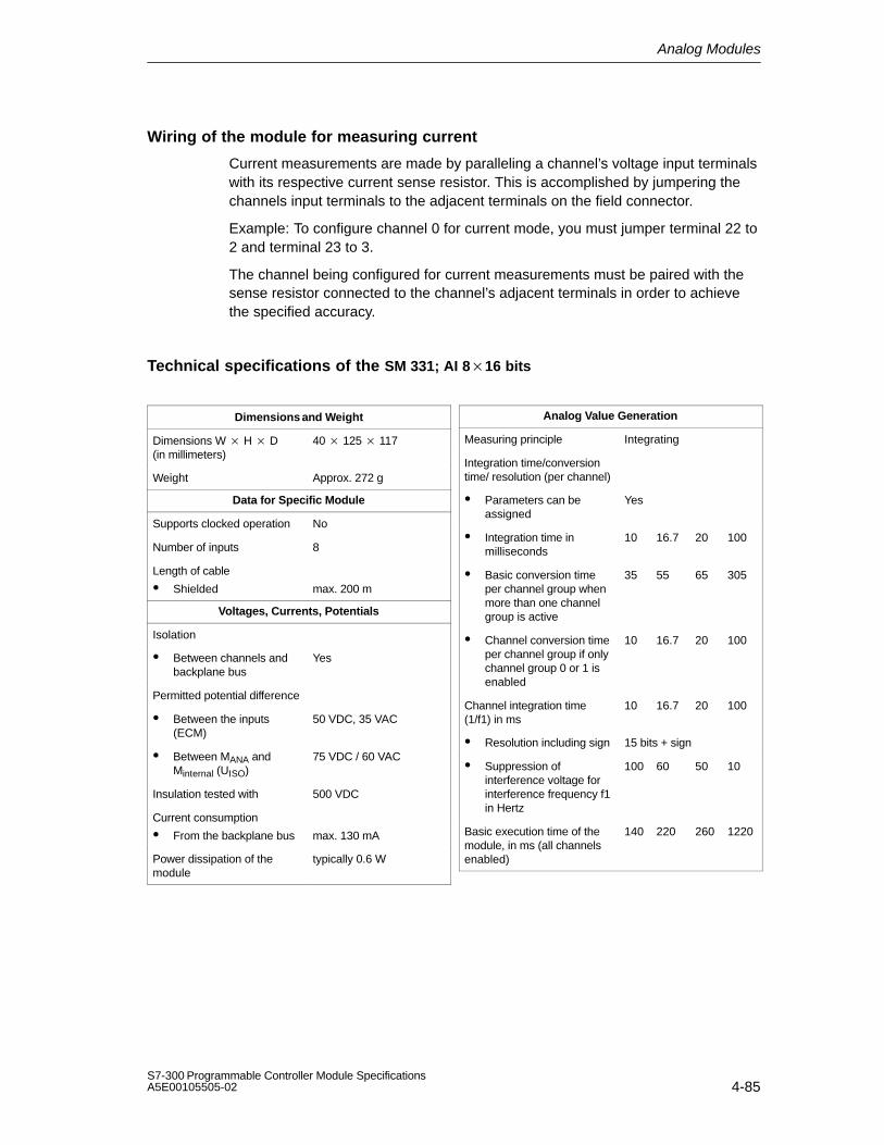
Analog Modules
4-85S7-300 Programmable Controller Module SpecificationsA5E00105505-02
Wiring of the module for measuring current
Current measurements are made by paralleling a channel’s voltage input terminalswith its respective current sense resistor. This is accomplished by jumpering thechannels input terminals to the adjacent terminals on the field connector.
Example: To configure channel 0 for current mode, you must jumper terminal 22 to2 and terminal 23 to 3.
The channel being configured for current measurements must be paired with thesense resistor connected to the channel’s adjacent terminals in order to achievethe specified accuracy.
Technical specifications of the SM 331; AI 816 bits
Dimensions and Weight
Dimensions W H D (in millimeters)
40 125 117
Weight Approx. 272 g
Data for Specific Module
Supports clocked operation No
Number of inputs 8
Length of cable
Shielded max. 200 m
Voltages, Currents, Potentials
Isolation
Between channels andbackplane bus
Yes
Permitted potential difference
Between the inputs(ECM)
50 VDC, 35 VAC
Between MANA andMinternal (UISO)
75 VDC / 60 VAC
Insulation tested with 500 VDC
Current consumption
From the backplane bus max. 130 mA
Power dissipation of themodule
typically 0.6 W
Analog Value Generation
Measuring principle Integrating
Integration time/conversiontime/ resolution (per channel)
Parameters can beassigned
Yes
Integration time inmilliseconds
10 16.7 20 100
Basic conversion timeper channel group whenmore than one channelgroup is active
35 55 65 305
Channel conversion timeper channel group if onlychannel group 0 or 1 isenabled
10 16.7 20 100
Channel integration time(1/f1) in ms
10 16.7 20 100
Resolution including sign 15 bits + sign
Suppression ofinterference voltage forinterference frequency f1in Hertz
100 60 50 10
Basic execution time of themodule, in ms (all channelsenabled)
140 220 260 1220

Analog Modules
4-86S7-300 Programmable Controller Module Specifications
A5E00105505-02
Suppression of Interference, Limits of Error
Noise suppression for f = n (f1 ± 1%), (f1 = interference frequency); n= 1, 2, ...
Common-mode noise(Ucm < 50 V)
> 100 dB
Series-mode interference(peak value ofinterference < ratedvalue of input range)
> 90 dB
Crosstalk between the inputs > 100 dB
Operational limit (over entiretemperature range, referredto input range)
UCM = 0 / UCM = ±50 V
Voltage input ±0.1% / ± 0.7%
Current input ±0.3% / ± 0.9%
Basic error (operational limit at 25° C referred to inputrange)
Voltage input ±0.05%
Current input ±0.05%
Temperature error (withreference to the input range)
±0.005%/K
Linearity error (with referenceto the input range)
±0.03%
Repeat accuracy (in thesteady state at 25°C, referredto the input range)
±0.025%
Status, Interrupts, Diagnostics
Interrupts
Hardware interrupt whenlimit has been exceeded
Programmablechannels 0 and 2
Diagnostic Interrupt Programmable
Diagnostic functions
Group error display
Diagnostics informationread-out
Programmable
Red LED (SF)
Possible
Data for Selecting a Sensor
Input range (rated values)/Input resistance
Voltage ± 5 V
1 to 5 V
± 10 V
/ 2MΩ/ 2MΩ/ 2MΩ
Current 0 to 20 mA;
± 20 mA
4 to 20 mA:
/ 250 Ω/ 250 Ω/ 250 Ω
Maximum input voltage forvoltage input (destructionlimit)
max. 50 V continuous
Maximum input current forcurrent input (destructionlimit)
max. 32 mA
Connection of the sensor
For measuring voltage Possible
For measuring current
As two-wire transmitter
As four-wire transmitter
Possible
Possible
Load of the two-wiretransmitter
max. 820 Ω

Analog Modules
4-87S7-300 Programmable Controller Module SpecificationsA5E00105505-02
4.18.1 Commissioning the SM 331; AI 8 16 bits
You set the mode of operation of the SM 331; AI 8 16 bits STEP 7.
Parameter
You will find a description of the general procedure for assigning parameters toanalog modules in Section 4.7.
An overview of the parameters that you can set and their default settings areshown in the table below.
Table 4-50 Parameters of the SM 331; AI 8 16 bits
Parameter Value Range DefaultSettings
ParameterType
Scope
Enable Diagnostic interrupt Hardware interrupt
upon limit violation
Yes/noYes/no
NoNo
Dynamic Module
Trigger for hardwareinterrupt
Upper limit value
Lower limit value
Constraint possible due to measuring range.
32511 to –32512
–<32512 to 32511
– DynamicChannel
Diagnostics Group diagnostics
With wire-breakcheck
Yes/no
Yes/no
No
NoStatic
Channelgroup
Measurement Measuring method Deactivated
U Voltage4DMU Current (4-wire transmitter)
U
Measuring range Refer to Section 4.18.2 for themeasuring ranges of the inputchannels that you can set.
10 V DynamicChannelgroup
Interferencesuppression
400 Hz; 60 Hz; 50 Hz; 10 Hz 50 Hz

Analog Modules
4-88S7-300 Programmable Controller Module Specifications
A5E00105505-02
Channel groups
The channels of the SM 331; AI 8 16 bits are arranged in four groups of two.You can only ever assign parameters to one channel group.
The table below shows which channels are parameterized as a channel group ineach case. You will need the channel group number to set the parameters in theuser program with an SFC.
Table 4-51 Assignment of Channels of the SM 331; AI 8 16 bits to Channel Groups
Channels ... ... form one Channel Group each
Channel 0
Channel 1Channel group 0
Channel 2
Channel 3Channel group 1
Channel 4
Channel 5Channel group 2
Channel 6
Channel 7Channel group 3
High speed update mode
In the high speed update mode, updates for the two channels in the group occurthree times faster than with multiple channel groups enabled.
Example: If channels 0 and 1 are enabled with 2.5 ms filtering, data updates forboth channels will be available to the PLC every 10 msec. (For other filter settings,the filter setting equals the update rate.)
The high speed update mode is only available when both channels are enabled onchannel group 0 or 1, in other words, the ”measuring method” parameter is set.However, only channel group 0 or only channel 1 (in other words, not bothtogether) must be enabled.
Special characteristic of channel groups for hardware interrupts
You can set hardware interrupts in STEP 7 for the channel groups 0 and 1. Note,however, that a hardware interrupt is set only for the first channel in the channelgroup in each case – in other words, for channel 0 or channel 2
Diagnostics
You will find the diagnostic messages that are grouped under the ”group diagnosis”parameter in Table 4-46, on page 4-78.

Analog Modules
4-89S7-300 Programmable Controller Module SpecificationsA5E00105505-02
4.18.2 Measuring Methods and Measuring Ranges of the SM 331;AI 8 16 bits
Measuring methods
You can set the following measuring methods for the input channels:
Voltage measurement
Current measurement
You perform the setting with the ”measuring method” parameter in STEP 7.
Unused channels
Set the ”measuring method” parameter for unused channels to ”disabled”. In thisway you shorten the scan time of the module.
Since configured inputs can remain unused because of the channel groupgeneration, you must take note of the following special characteristics of theseinputs to enable the diagnostic functions on the used channels.
Measuring range 1 to 5 V: Connect the unused input in parallel with a usedinput of the same channel group.
Current measurement 4 to 20 mA: Connect the unused input in series with aninput of the same channel group. Ensure that a current sense resistor isconnected for each active and unused channel.
Other ranges: Short the positive to the negative input of the channel.
Measuring ranges
You perform setting of the measuring ranges with the ”measuring range” parameterin STEP 7.
Table 4-52 Measuring Ranges of the SM 331; AI 8 x 16 bits
Method Selected Measuring Range Description
U: Voltage ±5 V1 to 5 V±10 V
You will find the digitized analog values inSection 4.3.1 in the voltage measuringrange
4DMU: Current (4-wiretransmitter)
from 0 to 20 mA±20 mAfrom 4 to 20 mA
You will find the digitized analog values inSection 4.3.1 in the current measuringrange

Analog Modules
4-90S7-300 Programmable Controller Module Specifications
A5E00105505-02
Default settings
The default settings of the module are ”voltage” for the measuring method ”10 V”for the measuring range. You can use this combination of measuring method andmeasuring range without parameterizing the SM 331; AI 8 16 bits in STEP 7.
Measuring errors with common-mode voltages
The SM 331; AI 8 x 16 bits can make measurements in the presence of AC or DCcommon mode voltage.
For AC common mode voltages at multiples of the filter frequency setting, therejection is accomplished by the integration period of the A/D converter and by thecommon mode rejection of the input amplifiers. For AC common mode voltages< 35 VRMS, the rejection ratio of > 100 dB results in negligible measurement error.
For DC common mode voltages, only the rejection of the input amplifier stage isavailable to minimize the effect of the common mode voltage. Therefore, someaccuracy degradation occurs in proportion to the common mode voltage. The worstcase error occurs with 50 VDC between one channel and the other sevenchannels. The calculated worst case error is0.7 % at 0 to 60 °C, and measurederror is typically ≤ 0.1% at 25 °C.
Special characteristic of parameter assignment to upper and lower limit values
The parameterizable limit values (triggers for hardware interrupt) differ for theSM 331; AI 8 x 16 bits from the range of values contained in Table 4-50.
The reason for this is that numerical methods in the module software for evaluatingthe process variables prevent values up to 32511 from being reported in somecases. The process input value at which a hardware interrupt for an underflow oroverflow occurs depends on the calibration factors for an individual channel andcan vary between the lower limits shown in the Table below and 32511 (7EFFH).
Limit values should not be set at values higher than the minimum potential limitvalues shown in the table below.

Analog Modules
4-91S7-300 Programmable Controller Module SpecificationsA5E00105505-02
Table 4-53 Minimum Possible Upper and Lower Limit Values of SM 331; AI 8 x 16 bits
Measuring Range Minimum Possible Upper Limit Value
Minimum Possible Lower Limit Value
±10 V 11.368 V314307AC6H
–11.369 V–314338537H
±5 V 5.684 V314307AC6H
–5.684 V–31430853AH
1 to 5 V 5.684 V323767E78H
0.296 V–4864ED00H
0 to 20 mA 22.737 mA314327AC8H
–3.519 mA–4864ED00H
4 to 20 mA 22.737 mA323787E7AH
1.185 mA–4864ED00H
±20 mA 22.737 mA314327AC8H
–22.737 mA–314328538H
Wire-break check
The wire-break check is available for the 1 to 5 V voltage range and the 4 to 20 mAcurrent range.
The following applies to both measuring ranges:
Enabled wire-break check, the analog input module enters a wire-break in thediagnosis if a current falls below 3.6 mA (0.9 V).
If you have enabled diagnostics interrupt during configuration, the moduleadditionally triggers a diagnostic interrupt.
If no diagnostic interrupt has been enabled, the illuminated SF LED is the onlyindication of the wire-break and you must evaluate the diagnostic bytes in the userprogram.
With a disabled wire-break check and enabled diagnostic interrupt, the moduletriggers a diagnostic interrupt when the underflow is reached.

Analog Modules
4-92S7-300 Programmable Controller Module Specifications
A5E00105505-02
4.19 Analog Input ModuleSM 331; AI 8 16 bits(6ES7 331-7NF10-0AB0)
Order number
6ES7 331-7NF10-0AB0
Characteristics
The isolated analog input module SM 331; AI 8 × 16 bits has the followingcharacteristic features:
8 isolated inputs in 4 channel groups
Measured-value resolution 15 bits + sign
Rapid measured value updating for up to 4 channels
Measuring method selectable per channel group
Programmable diagnostics
Programmable diagnostic interrupt
8 channels with limit monitoring
Programmable hardware interrupt when limit has been exceeded
Programmable end-of-scan-cycle interrupt
Electrical isolation to the backplane bus interface
Special feature
When you use the SM 331; AI 8 × 16 bits in the distributed peripheral ET 200M,you must have one of the following IM153-x:
IM 153-1 6ES7 153-1AA03-0XB0, E 01
IM 153-2 6ES7 153-2AA02-0XB0, E 05
IM 153-2 6ES7 153-2AB01-0XB0, E 04

Analog Modules
4-93S7-300 Programmable Controller Module SpecificationsA5E00105505-02
Terminal connection diagram and block diagram of the SM 331; AI 8 × 16 bits
2
20
1
3
4
5
6
7
8
9
10
11
12
13
14
15
16
17
18
19
DCto
DC
L M
Interfacemodule
logicand
back-planebus
ADC
ADC
ADC
22
40
21
23
24
25
26
27
28
29
30
31
32
33
34
35
36
37
38
39
M
L+
Chn. 0
Chn. 1
Chn. 2
Chn. 3
250
250
250
250
250
250
250
250
V
M0+
M0–
A
V
M1–
M1+
A
V
M2+
M2–
A
V
M3–
M3+
A
Chn. 4
Chn. 5
Chn. 6
Chn. 7
V
M4+
M4–
A
V
M5–
M5+
A
V
M6+
M6–
A
V
M7–
M7+
A
ADC
SF
SF
Fault indicator – red
Figure 4-34 Module View and Block Diagram of the SM 331; AI 8 x 16 bits

Analog Modules
4-94S7-300 Programmable Controller Module Specifications
A5E00105505-02
Technical specifications of the SM 331; AI 8 16 bits
Dimensions and Weight
Dimensions W × H × D (in millimeters)
40 × 125 × 117
Weight Approx. 272 g
Data for Specific Module
Supports clocked operation
No
Number of inputs 8
Length of cable
Shielded max. 200 m
Voltages, Currents, Potentials
Power rated voltage of theelectronics L+
24 VDC
Reverse polarity protection Yes
Isolation
Between channels andbackplane bus
Yes
Between channels andpower supply of theelectronics
Yes
Between the channels
In groups of
Yes
2
Permitted potential difference
Between the inputs (ECM) 75 VDC / 60 VAC
Between MANA andMinternal (UISO)
75 VDC / 60 VAC
Insulation tested with 500 VAC
Current consumption
From the backplane bus max. 100 mA
From the power supply L+ max. 200 mA
Power dissipation of the module typ. 3.0 W
Analog Value Generation
Measuring principle Integrating
Integration time/conversiontime/ resolution (per channel)
Parameters can beassigned
Yes
Basic conversion time inms (8-channel mode)
95/83/72/23
Basic conversion time inms (4-channel mode)
101)
Resolution including sign 16 bits
Noise suppression forfrequency f1 in Hz
All2)/50/60/400
Smoothing of the measuredvalues
None / low/ average/ high
Basic execution time of themodule, in ms(8-channel-mode)
190/166/144//46
Basic execution time of themodule, in ms(4-channel-mode)
101)
Suppression of Interference, Limits of Error
Interference suppression for F = n × (f1 ± 1%)(f1 = interference frequency, n = 1, 2, ...)
Common-modeinterference (Ucm < AC 60 V)
> 100 dB
Series-mode interference(peak value of interference< rated value of inputrange)
>90 dB 3)
Crosstalk between the inputs > 100 dB
Operational limit (in the entire temperature range, withreference to the input range)
Input voltage 0.1%
Input current 0.1%
Basic error (operational limit at 25 °C, referred to inputrange)
Voltage input 0.05%
Current input 0.05%
Temperature error (withreference to the input range)
0.005%/K

Analog Modules
4-95S7-300 Programmable Controller Module SpecificationsA5E00105505-02
Linearity error (with reference tothe input range)
0.01%
Repeat accuracy (in the steadystate at 25 °C, referred to theinput range)
0.01%
Status, Interrupts, Diagnostics
Interrupts
Hardware interrupt if thelimit value is exceeded
Programmablechannels 0 – 7
Hardware interrupt at endof cycle
Parameters can beassigned
Diagnostic interrupt Parameters can beassigned
Diagnostic functions Parameters can beassigned
Group error display Red LED (SF)
Diagnostics informationread-out
Possible
Data for Selecting a Sensor
Input range (rated values) /input resistance
Voltage 5 V / 2 MΩ1 to 5 V / 2 MΩ 10 V / 2 MΩ
Current 0 to 20 mA / 250 Ω4 to 20 mA / 250 Ω 20 mA / 250 Ω
Maximum input voltage forvoltage input (destruction limit)
35 VDC continuous;75 VDC for max. 1 s(duty factor 1:20)
Maximum input current forcurrent input (destruction limit)
40 mA
Connection of the sensor
For measuring voltage Possible
For measuring current
As two-wire transmitter Possible with separatesupply for thetransmitter
As four-wire transmitter Possible
1) Interference frequency for 4-channel mode is ”All”2) Interference frequencies 50/60/400 Hz are designated as
”All”3) Series-mode rejection for 8-channel mode is reduced
as follows:50 Hz > 70 db60 Hz > 70 db400 Hz > 80 dB50/60/400 Hz > 90 dB

Analog Modules
4-96S7-300 Programmable Controller Module Specifications
A5E00105505-02
4.19.1 Commissioning the SM 331; AI 8 16 bits
You set the mode of operation of the SM 331; AI 8 × 16 bits in STEP 7.
Parameter
You will find a description of the general procedure for parameterizing the SM 331;AI 8 × 16 bits, in section 4.7.
Parameterization restrictions when using the analog input module SM 331;AI 8 x 16 bits with PROFIBUS masters that only support DPV0.
When you use the isolated analog input module SM 331; AI 816 bits in anET200M PROFIBUS slave system with a PROFIBUS master which is not an S7master, certain parameters are not permitted. Masters that are not S7 masters donot support hardware interrupts. So all the parameters associated with thesefunctions are deactivated. The deactivated parameters are hardware interruptenable, hardware restrictions and end-of-scan-cycle interrupt enable. All the otherparameters are permitted.

Analog Modules
4-97S7-300 Programmable Controller Module SpecificationsA5E00105505-02
An overview of the parameters that you can set and their default settings areshown in the table below.
Table 4-54 Parameters of the SM 331; AI 8 x 16 bits
Parameter Value Range Default Parameter ScopeParameter Value Range Defaultsettings
ParameterType
Scope
Enable
Hardware interrupt ifthe limit value isexceeded
Hardware interrupt atend of cycle
Diagnostic Interrupt
Yes/no
Yes/no
Yes/no
No
No
No
Dynamic
Dynamic
Dynamic
Module
Hardware interrupt trigger
Upper limit
Lower limit
32511 to –32512
–32512 to 32511
––
Dynamic
Dynamic
Channel
Channel
Diagnostics
Group diagnostics
Wire-break check
Yes/no
Yes/no
No
No
Static Channel
Channel
Measurement
Module mode
Interferencesuppression
8 channels
4 channels
50 Hz60 Hz400 Hz50/60/400 Hz
Yes
No
50/60/400 Hz
Dynamic Module
Channelgroup
Smoothing None
Low
Average
High
None Dynamic Channelgroup
Measuring method MeasuringRange:
Dynamic Channelgroup
Deactivated
Voltage 5 V
1 to 5 V
10 V
10 V
Current (4-wiretransmitter)
0 to 20 mA
4 to 20 mA
20 mA
4 to 20 mA

Analog Modules
4-98S7-300 Programmable Controller Module Specifications
A5E00105505-02
Channel groups
The channels of the SM 331; AI 8 ×16 bits are arranged in groups of two inputseach. You must assign the same parameters to both the inputs in a group. Theinterrupt limits are the exception here.
Table 4-55 shows which channels of the isolated analog input module SM 331; AI 8 × 16 bits are configured as a channel group. To set the parameters by meansof SFC in the user program, you need the numbers of the channel groups. Detailedinformation on this can be found in Appendix A.
Table 4-55 Assignment of the Channels of the Isolated Analog Input Module SM 331; AI 8 16 bits to Channel Groups
Channels ... ... form one channel group each
Channel 0
Channel 1Channel group 0
Channel 2
Channel 3Channel group 1
Channel 4
Channel 5Channel group 2
Channel 6
Channel 7Channel group 3
Operating states
The following modes are available for the isolated analog input module SM 331; AI8 16 bits:
8 channels
4 channels

Analog Modules
4-99S7-300 Programmable Controller Module SpecificationsA5E00105505-02
4.19.2 8-Channel Mode
Description of the module cycle
In 8-channel mode, the isolated analog input module SM 331; AI 8 16 bitsswitches between the two channels in each group. As the module contains fouranalog/digital converters (ADC), all four of the ADCs convert simultaneously forchannels 0, 2, 4 and 6. Once the even-numbered channels have been convertedall the ADCs simultaneously convert for the odd-numbered channels 1, 3, 5 and 7(see Figure 4-35).
Scan time
Start analog conversion(simultaneous)
K0 K2 K4 K6
K1 K3 K5 K7
Start analog conversion(simultaneous)
Figure 4-35 8-Channel Mode Cycle

Analog Modules
4-100S7-300 Programmable Controller Module Specifications
A5E00105505-02
Scan time of the module
In the 8-channel mode of the SM 331; AI 8 × 16 bits, the channel conversion timeis guided by the interference frequency set. When you set an interferencefrequency of 50 Hz, the channel conversion time including communication time is76 ms. When you set an interference frequency of 60 Hz, the channel conversiontime is 65 ms. When you set an interference frequency of 400 Hz, the channelconversion time is reduced to 16 ms. When you set an interference frequency of50, 60 and 400 Hz, the channel conversion time is 88 ms. The module must thenbe switched over to the other channel of the group by means of opto-MOS relays.Opto-MOS relays need 7 ms to switch and settle. Table 4-56 shows the scan timesof the module at certain interference frequencies.
Table 4-56 Scan Times in 8-Channel Mode
Interference frequency(Hz)
Channel scan time(ms)
Module scan time (All channels)
50 83 166
60 72 144
400 23 46
400/60/50 95 190

Analog Modules
4-101S7-300 Programmable Controller Module SpecificationsA5E00105505-02
4.19.3 4 Channel-Mode
Description of the module cycle
In 4-channel mode, the SM 331; AI 8 16 bits does not switch over between thechannels of the individual groups. As the module contains four analog/digitalconverters (ADC), all four of the ADCs convert simultaneously for channels 0, 2, 4and 6.
Scan time
Start analog conversion(simultaneous)
K0 K2 K4 K6
Figure 4-36 4-Channel Mode Cycle
Scan time of the module
In 4-channel mode, the channel conversion time including communication time ofthe SM 331; AI 8 × 16 bits is 10 ms. As the module does not switch over betweenthe channels in a group, the channel scan time and the module scan time are the same: 10 ms.

Analog Modules
4-102S7-300 Programmable Controller Module Specifications
A5E00105505-02
4.19.4 Measuring Methods and Measuring Ranges of the SM 331; AI 8 16 bits
Measuring methods
You can set the following measuring methods for the input channels:
Voltage measurement
Current measurement (4-wire transmitter)
You perform the setting with the ”measuring method” parameter in STEP 7.
Unused channels
Set the ”measuring method” parameter for unused channels to ”disabled”. In thisway you shorten the scan time of the module.
Since configured inputs can remain unused because of the channel groupgeneration, you must take note of the following special characteristics of theseinputs to enable the diagnostic functions on the used channels.
Measuring range 1 to 5 V: Connect the unused input in parallel with a usedinput of the same channel group.
Current measurement 4 to 20 mA: Connect the unused input in series with aninput of the same channel group. Ensure that a current sense resistor isconnected for each active and unused channel.
Other ranges: Short the positive to the negative input of the channel.

Analog Modules
4-103S7-300 Programmable Controller Module SpecificationsA5E00105505-02
Wire-break check
The wire-break check is a module software function that is available for all thevoltage ranges and the current range of 4 to 20 mA.
With the ± 5 V, 1 to 5 V or ± 10 V measuring ranges and an enabled wire-breakcheck, the isolated analog input module enters a wire-break in the diagnosiswhen the process value achieves a positive full-scale deflection (32768). If youenabled the diagnostic interrupt during configuration, the analog input modulealso triggers a diagnostic interrupt.
If the diagnostic interrupt has not been enabled, the illuminated SF display isthe only indication that there is a wire-break. You must then assess thediagnosis bytes in the user program.
With a measuring range of 4 to 20 mA and an enabled wire-break check, theisolated analog input module enters wire-break in the diagnosis when theprocess value falls below 3.6 mA. If you enabled the diagnostic interrupt duringconfiguration, the analog input module also triggers a diagnostic interrupt.
If the diagnostic interrupt has not been enabled, the illuminated SF display isthe only indication that there is a wire-break. You must then assess thediagnosis bytes in the user program.
If the wire-break check is not enabled, the isolated analog input module triggersa diagnostic interrupt if the limit value for underflow is not reached.
Measuring ranges
You perform setting of the measuring ranges with the ”measuring range” parameterin STEP 7.
Table 4-57 Measuring Ranges of the SM 331; AI 8 × 16 bits
Method Selected Output Range Description
Voltage 5 VFrom 1 to 5 V 10 V
You will find the digitalanalog values inSection 4.3.1 in the voltage
Current (4-wire transmitter) From 0 to 20 mAFrom 4 to 20 mA 20 mA
and current output ranges

Analog Modules
4-104S7-300 Programmable Controller Module Specifications
A5E00105505-02
Short circuit to M or L
If you short an input channel to M or L, the module does not suffer any damage.The channel continues to issue valid data; neither is a diagnosis reported.
Overflow, underflow and hardware interrupt limits
The diagnosis operating limits for overflow and underflow for some of themeasuring ranges differ from those given in section 4.3.1 of the manual. In somecases, numerical methods in the module software to assess the process variablesprevent values up to 32511 being signaled.
Hardware interrupt limits must not be set to values greater than the smallestpossible limit value of the overflow or underflow operating limits for theend-of-scan-cycle interrupt in section 4.3.1.
End-of-scan-cycle interrupt
By enabling the end-of-scan-cycle interrupt, you can synchronize a process withthe conversion cycle of the module. The interrupt occurs when the conversion of allthe enabled channels is complete.
Table 4-58 Content of the 4 Bytes with Additional Information from OB40 during a HardwareInterrupt or an End-of-Scan-Cycle Interrupt
Content of the 4 bytes withadditional information
27 26 25 24 23 22 21 20 Byte
Analog 2 bits per channel to identify the rangespecialmar-
Upper limit exceededin channel
7 6 5 4 3 2 1 0 0kers
Lower limit exceededin channel
7 6 5 4 3 2 1 0 1
End-of-scan-cycleevent
X 2
Unassigned bit 3
Analog Modules
4-105S7-300 Programmable Controller Module SpecificationsA5E00105505-02
4.20 Analog Input Module SM 331; AI 8 13 bits;(6ES7 331-1KF00-0AB0)
Order number
6ES7 331-1KF00-0AB0
Characteristics
The analog input module SM 331; AI 8 13 bits has the following characteristicfeatures:
8 inputs
Measured-value resolution 12 bits + sign
Measuring method selectable
– Voltage
– Current
– Resistors
– Bulb resistor
Isolated against the backplane bus interface

Analog Modules
4-106S7-300 Programmable Controller Module Specifications
A5E00105505-02
Terminal connection diagram and block diagram of the SM 331; AI 8 13 bits
The following diagram uses channels 4 to 7 to show some connection examplesfor the various measuring methods. These connection examples apply to allchannels accordingly (channels 0 to 7).
S–
2
20
1
3
4
5
6
7
8
9
10
11
12
13
14
15
16
17
18
19
22
40
21
23
24
25
26
27
28
29
30
31
32
33
34
35
36
37
38
39
Channel number
2
1
3
4
5
6
7
0
2
1
3
4
5
6
7
0
2
1
3
4
5
6
7
0
2
1
3
4
5
6
7
0
Logicandbackplanebusinterface
ADC
Electrical isolation
Internal supply
Current source
+ 5 V frombackplane bus
Ch 0
Ch 1
Ch 2
Ch 3M+
Connection examples
Multiplexer
Ch 4
Ch 5
Ch 6
Ch 7
M–
M–
M+
M–
I+
M–
U+
A
mV
V
I+
M+
S–
U+
S–
M+
U+
I+
S–
U+
I+
M+
M–
M–
M+
I+
M–
U+
I+
M+
S–
U+
S–
M+
U+
I+
S–
U+
I+
S–
M–
Figure 4-37 Module View and Block Diagram of the Analog Input Module SM 331; AI 8 13 bits
Note
When connecting the voltage and current sensors, make sure that you do notexceed the maximum permitted common-mode voltage UCM of 2 V between theinputs. So to prevent measuring errors, interconnect the individual M– terminals.
It is not necessary to interconnect the M– terminals when measuring resistors andresistance temperature detectors.

Analog Modules
4-107S7-300 Programmable Controller Module SpecificationsA5E00105505-02
Technical specifications of the SM 331; AI 8 13 bits
Dimensions and Weight
Dimensions W H D (in millimeters)
40 125 117
Weight Approx. 250 g
Data for Specific Module
Supports clocked operation No
Number of inputs
For resistance-typesensor
8
8
Length of cable
Shielded
max. 200 m
max. 50 m at 50 mV
Voltages, Currents, Potentials
Power rated voltage of theelectronics
from bus –5 V
Constant current forresistance-type sensor
Resistancetemperature detectorsand resistancemeasurement 0 to 600 Ω
0.83 mA
Resistancemeasurement 0 to 6 kΩ
0.25 mA
Isolation
Between channels andbackplane bus
Yes
Between the channels No
Permitted potentialdifference
Between the inputs(ECM)
2.0 VDC
Between MANA andMinternal (UISO)
75 VDC / 60 VAC
Insulation tested with 500 VDC
Current consumption
From the backplanebus
max. 90 mA
Power dissipation of themodule
typ. 0.4 W
Analog Value Generation
Measuring principle Integrating
Integration time/conversiontime/ resolution (perchannel)
Parameters can beassigned
Yes
Noise suppression forfrequency f1 in Hz
50 60
Integration time inmilliseconds
20 162/3
Basic conversion timeincluding Integrationtime in milliseconds
66 55
Additional conversiontime for measuringresistance, in ms
66 55
Resolution in bits (incl.overrange)
13bits
13 bits
Suppression of Interference, Limits of Error
Noise suppression for f = n (f1 1 %),(f1 = interference frequency) n = 1.2
Common-modeinterference (UCM < 2 V)
> 86 dB
Series-mode noise(peak value ofnoise < nominal valueof input range)
> 40 dB
Crosstalk between theinputs
> 50 dB
Operational limit (in the entire temperature range, withreference to the input range)
Voltage input 5 V 10 V1 to 5 V0 to 10 V
0.6 %
50 mV 500 mV1 V
0.5 %
Current input 20 mA0 to 20 mA4 to 20 mA
0.5 %
Resistors 0 to 6 kΩ0 to 600 Ω
0.5 % 0.5 %
Resistance thermometer
Pt 100 standard
1.2 K
Pt 100climate
1 K

Analog Modules
4-108S7-300 Programmable Controller Module Specifications
A5E00105505-02
Basic error (operational limit at 25 C referred to inputrange)
Voltage input 5V 10 V1 to 5 V0 to 10 V
0.4 %
50 mV 500 mV1 V
0.3 %
Current input 20 mA0 to 20 mA4 to 20 mA
0.3 %
Resistors 0 to 6 kΩ0 to 600 Ω
0.3 % 0.3 %
Resistance thermometer
Pt 100 standard
1 K
Pt 100climate
0.8 K
Temperature error (withreference to the inputrange)
0.06 %/K / 0.06 K/K
Linearity error (withreference to the inputrange)
0.1 % / 0.1 K
Repeatability (in steadystate at 25 C referred toinput range)
0.1 % / 0.1 K
Status, Interrupts, Diagnostics
Interrupts None
Diagnostic functions None
Data for Selecting a Sensor
Input range (ratedvalues)/Input resistance
Voltage 50 mV
500 mV
1 V
5 V
10 V
1 to 5 V;
0 to 10 V
100 kΩ
Current 20 mA
0 to 20 mA;
4 to 20 mA:
50 Ω
Resistors 0 to 6 kΩ0 to 600 Ω
100 MΩ
Resistance thermometer
Pt 100standard /climate
100 MΩ
Maximum input voltage forvoltage input U+(destruction limit)
max. 30 V continuous
Maximum input voltage forvoltage input M+, M-, S- (destruction limit)
max. 12 V continuous;30 V for max. 1 s
Maximum input current forcurrent input I+(destruction limit)
40 mA
Connection of the sensor
For measuring voltage Possible
For measuring current
As two-wire transmitter Possible, with externalsupply
As four-wire transmitter Possible
For measuringresistance
With two-conductorconnection
Possible
With three-conductorconnection
Possible
With four-conductorconnection
Possible
Characteristic linearization Parameters can beassigned
For RTD Pt 100 standard / climate
Technical unit fortemperaturemeasurement
Degrees Celsius, degrees Fahrenheit, Kelvin

Analog Modules
4-109S7-300 Programmable Controller Module SpecificationsA5E00105505-02
4.20.1 Parameters of the SM 331; AI 8 13 bits
Parameter
You will find a description of the general procedure for assigning parameters to theanalog modules in Section 4.7.
An overview of the parameters that you can set and their default settings areshown in the table below.
Table 4-59 Parameters of the SM 331; AI 8 13 bits
Parameter Value Range DefaultSettings
ParameterType
Scope
Measurement Measuring Method Deactivated
U VoltageI CurrentR ResistorsRTD Bulb resistor
U
Measuring Range Voltage50 mV; 500 mV; 1 V; 1 to 5 V;5 V; 0 to 10 V; 10 V
10 VDynamic Channel
Current0 to 20 mA; 4 to 20 mA; 20 mA 20 mA
Resistors0 to 600 Ω; 0 to 6 kΩ 600 Ω
Bulb resistor (linear)Pt 100 climate; Pt 100 standard
Pt 100standard
InterferenceSuppression
50 Hz; 60 Hz 50 HzModule
Temperature unit Degrees Celsius, degrees Fahrenheit,Kelvin*
* Pt 100 standard only

Analog Modules
4-110S7-300 Programmable Controller Module Specifications
A5E00105505-02
4.20.2 Measuring Methods of the SM 331; AI 8 13 bits
Measuring methods
You can set the following measuring methods for the input channels:
Voltage measurement
Current measurement
Resistance test
You perform the setting with the ”measuring method” parameter in STEP 7.
Unused channels
Set the ”measuring method” parameter for unused channels to ”disabled”. In thisway you shorten the scan time of the module.

Analog Modules
4-111S7-300 Programmable Controller Module SpecificationsA5E00105505-02
4.21 Analog Input Module SM 331; AI 8 12 bits;(6ES7 331-7KF02-0AB0)
Order number
6ES7 331-7KF02-0AB0
Characteristics
The analog input module SM 331; AI 8 12 bits has the following characteristicfeatures:
8 inputs in 4 channel groups
Measured-value resolution; settable per group (depending on the integrationtime set)
– 9 bits + sign
– 12 bits + sign
– 14 bits + sign
Measuring method selectable per channel group:
– Voltage
– Current
– Resistors
– Temperature
Arbitrary measuring range selection per channel group
Programmable diagnostics
Programmable diagnostic interrupt
Two channels with limit monitoring
Programmable hardware interrupt when limit has been exceeded
Isolated against the backplane bus interface
Isolated against load voltage (except when at least one coding key is inserted in position D)
Resolution
The resolution of the measured value is a direct function of the integration timeselected. In other words the longer the integration time for an analog input channel,the more accurate the resolution of the measured value will be (see TechnicalSpecifications of the module and Table 4-6 on page 4-11).

Analog Modules
4-112S7-300 Programmable Controller Module Specifications
A5E00105505-02
Terminal connection diagram and block diagram of the SM 331; AI 8 12 bits
M3
Comp–/ Mana
Fault indicator – red
Thermocouples,voltage measurementcurrent measurement
Resistance test
M0 +
M0
M1 +
Comp +
SF Internal supply
MM
L+Current source
Multi-plexer
Meas. rangemodule
Ext. compensation
None
ADC
Isolation
Backplane businterface
SF
+
Int.Comp.
CH0 M0 + CH0M0IC0 +CH1
M1 IC0
M2 + CH2 M1 + CH2M2 M1
M3 + CH3 IC1 +
IC1
M4 +
M4
M5 +
CH4 M2 + CH4M2IC2 +CH5
M5 IC2
M6 + CH6 M3 + CH6M6 M3
M7 + CH7 IC3 +
M7 IC3
Comp
24V
T
Figure 4-38 Module View and Block Diagram of the Analog Input Module SM 331; AI 8 12 bits
The input resistances depend on the measuring range selected (see TechnicalSpecifications).

Analog Modules
4-113S7-300 Programmable Controller Module SpecificationsA5E00105505-02
Technical specifications of the SM 331; AI 8 12 bits
Dimensions and Weight
Dimensions W H D (in millimeters)
40 125 117
Weight Approx. 250 g
Data for Specific Module
Supports clocked operation No
Number of inputs
For resistance-typesensor
8
4
Length of cable
Shielded
max. 200 m
max. 50 m at 80 mV andthermocouples
Voltages, Currents, Potentials
Rated supply voltage of theelectronics L +
24 VDC
Reverse polarityprotection
Yes
Power supply of thetransmitters
Supply current max. 60 mA (per channel)
Short-circuit-proof Yes
Constant current forresistance-type sensor
typ. 1.67 mA
Isolation
Between channels andbackplane bus
Yes
Between channels andpower supply of theelectronics
Yes
Permitted potentialdifference
Between inputs andMANA (UCM)
– At signal = 0 V
– Not for 2-wiretransmitter
2.5 VDC
Between the inputs(ECM)
2.5 VDC
Between MANA andMinternal (UISO)
75 VDC / 60 VAC
Insulation tested with 500 VDC
Current consumption
From the backplane bus max. 50 mA
From the backplane busL +
max. 30 mA (without two-wiretransmitter)
Power dissipation of themodule
typ. 1 W
Analog Value Generation
Measuring principle Integrating
Integration time/conversiontime/ resolution (perchannel)
Parameters can beassigned
Yes
Integration time inmilliseconds
2.5 162/3 20 100
Basic conversion timeincluding Integrationtime in milliseconds
3 17 22 102
Additional conversiontime for measuringresistance, in msor
1 1 1 1
Additional conversiontime for open-circuitmonitoring, in msor
10 10 10 10
Additional conversiontime for measuringresistance andopen-circuit monitoring,in ms
16 16 16 16
Resolution in bits (incl.overrange)
9bits
12 bits
12bits
14 bits
Noise suppression forfrequency f1 in Hz
400 60 50 10
Basic execution time ofthe module, in ms (allchannels enabled)
24 136 176 816
Smoothing of the measuredvalues
None

Analog Modules
4-114S7-300 Programmable Controller Module Specifications
A5E00105505-02
Suppression of Interference, Limits of Error
Noise suppression for F = n (f1 1 %),(f1 = interference frequency)
Common-modeinterference(UCM < 2.5 V)
> 70 dB
Series-mode noise(peak value ofnoise <nominal value ofinput range)
> 40 dB
Crosstalk between theinputs
> 50 dB
Operational limit (in the entire temperature range, withreference to the input range)
Voltage input 80 mV 1 %
250 to 1000mV
0.6 %
2.5 to 10 V 0.8 %
Current input 3.2 to 20 mA 0.7 %
Resistors 150Ω; 300Ω; 600 Ω
0, 7 %
Thermocouple Type E, N, J,K, L
1, 1 %
Resistance thermometer
Pt 100/Ni 100
0, 7 %
Pt 100climate
0, 8 %
Basic error (operational limit at 25 C referred to inputrange)
Voltage input 80 mV 0.7 %
250 to1000mV
0.4 %
2.5 to 10 V 0.6 %
Current input 3.2 to 20 mA 0.5 %
Resistors 150Ω; 300Ω; 600 Ω
0.5 %
Thermocouple Type E, N, J,K, L
0.7 %
Resistance thermometer
Pt 100/Ni 100
0.5 %
Pt 100climate
0.6 %
Temperature error (withreference to the input range)
0.005 %/K
Linearity error (withreference to the input range)
0.05 %
Repeatability (in steadystate at 25 C referred toinput range)
0.05 %
Temperature error of internalcompensation
1 %
Status, Interrupts, Diagnostics
Interrupts
Hardware interruptwhen limit has beenexceeded
Programmablechannels 0 and 2
Diagnostic Interrupt Programmable
Diagnostic functions
Group error display
Diagnostics informationread-out
Programmable
Red LED (SF)
Possible
Data for Selecting a Sensor
Input range (ratedvalues)/Input resistance
Voltage 80 mV
250 mV
500 mV
1000 mV
2.5 V
5 V
1 to 5 V;
10 V
/10 MΩ/10 MΩ/10 MΩ/10 MΩ/100kΩ/100kΩ/100kΩ/100kΩ
Current 3.2 mA
10 mA
20 mA
0 to 20 mA;
4 to 20 mA:
/25 Ω/25 Ω/25 Ω/25 Ω/25 Ω
Resistors 150 Ω300 Ω600 Ω
/10 ΜΩ/10 ΜΩ/10 ΜΩ
Thermocouples Type E, N, J,K, L
/10 ΜΩ
Resistance thermometer
Pt 100,Ni 100
/10 ΜΩ
Maximum input voltage forvoltage input (destructionlimit)
max. 20 V continuous; 75 V for max. 1 s(duty factor 1:20)
Maximum input current forcurrent input (destructionlimit)
40 mA

Analog Modules
4-115S7-300 Programmable Controller Module SpecificationsA5E00105505-02
Connection of the sensor
For measuring voltage Possible
For measuring current
As two-wire transmitter
As four-wire transmitter
Possible
Possible
For measuringresistance
With two-conductorconnection
With three-conductorconnection
With four-conductorconnection
Possible
Possible
Possible
Load of the two-wiretransmitter
max. 820 Ω
Characteristic linearization
For thermocouples
Parameters can beassigned
Type E, N, J, K, L
For RTD Pt 100 (standard, climate range)Ni 100 (standard, climate range)
Temperature compensation Parameters can beassigned
Internal temperaturecompensation
Possible
External temperaturecompensation withcompensating box
Possible
Compensation for 0 Ccomparison pointtemperature
Possible
Technical unit fortemperaturemeasurement
Degrees Celsius
4.21.1 Commissioning the SM 331; AI 8 12 bits
You set the mode of operation of the SM 331; AI 8 12 bits by means ofmeasuring range modules on the module and in STEP 7.
Measuring range module
If necessary, the measuring range modules must be replugged to change themeasuring method and the measuring range. The steps you have to perform to dothis are described in detail in Section 4.4.
The corresponding table in Section 4.21.2 tells you which assignment you have toselect for which measuring method and measuring range. In addition, thenecessary settings are embossed on the module.
Default settings for measuring range module
The measuring range modules are preset to ”B” (voltage; 10 V) when themodule is supplied.
To use the following preset measuring methods and measuring ranges, you onlyhave to change the measuring range module to the corresponding setting.Parameter assignment in STEP 7 is not necessary.

Analog Modules
4-116S7-300 Programmable Controller Module Specifications
A5E00105505-02
Table 4-60 Default Settings of the SM 331; AI 8 12 bits Using Measuring Range Modules
Measuring Range Module Setting
Measuring Method Measuring Range
A Voltage 1000 mV
B Voltage 10 V
C Current,Four-wire transmitter
4 to 20 mA
D Current,Two-wire transmitter
4 to 20 mA
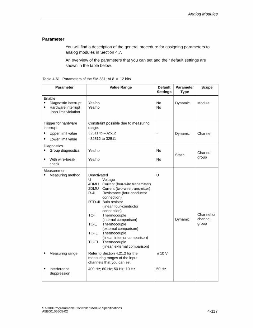
Analog Modules
4-117S7-300 Programmable Controller Module SpecificationsA5E00105505-02
Parameter
You will find a description of the general procedure for assigning parameters toanalog modules in Section 4.7.
An overview of the parameters that you can set and their default settings areshown in the table below.
Table 4-61 Parameters of the SM 331; AI 8 12 bits
Parameter Value Range DefaultSettings
ParameterType
Scope
Enable Diagnostic interrupt Hardware interrupt
upon limit violation
Yes/noYes/no
NoNo
Dynamic Module
Trigger for hardwareinterrupt
Upper limit value
Lower limit value
Constraint possible due to measuring range.32511 to –32512
–32512 to 32511– Dynamic Channel
Diagnostics Group diagnostics
With wire-breakcheck
Yes/no
Yes/no
No
NoStatic
Channelgroup
Measurement Measuring method Deactivated
U Voltage4DMU Current (four-wire transmitter)2DMU Current (two-wire transmitter)R-4L Resistance (four-conductor
connection)RTD-4L Bulb resistor
(linear, four-conductor connection)
TC-I Thermocouple (internal comparison)
TC-E Thermocouple (external comparison)
TC-IL Thermocouple (linear, internal comparison)
TC-EL Thermocouple (linear, external comparison)
U
DynamicChannel orchannelgroup
Measuring range Refer to Section 4.21.2 for themeasuring ranges of the inputchannels that you can set.
10 V
InterferenceSuppression
400 Hz; 60 Hz; 50 Hz; 10 Hz 50 Hz

Analog Modules
4-118S7-300 Programmable Controller Module Specifications
A5E00105505-02
Channel groups
The channels of the SM 331; AI 8 12 bits are arranged in four groups of two.You can only ever assign parameters to one channel group.
The analog input module SM 331; AI 8 12 bits has a measuring range modulefor each channel group.
The table below shows which channels are parameterized as a channel group ineach case. You will need the channel group number to set the parameters in theuser program with an SFC.
Table 4-62 Assignment of Channels of the SM 331; AI 8 12 bits to Channel Groups
Channels ... ... form one Channel Group each
Channel 0
Channel 1Channel group 0
Channel 2
Channel 3Channel group 1
Channel 4
Channel 5Channel group 2
Channel 6
Channel 7Channel group 3
Special characteristic of channel groups with resistance measurement
If you use the resistance measurement method, there is only one channel perchannel group. The ”2nd” channel of each group is used for current injection (IC).
The measured value is obtained by accessing the ”1st” channel of the group. The”2nd” channel of the group has the default carry value ”7FFFH”.
Special characteristic of channel groups for hardware interrupts
You can set hardware interrupts in STEP 7 for the channel groups 0 and 1. Note,however, that a hardware interrupt is set only for the first channel in the channelgroup in each case – in other words, for channel 0 or channel 2
Diagnostics
You will find the diagnostic messages that are grouped under the ”group diagnosis”parameter in Table 4-46, on page 4-78.

Analog Modules
4-119S7-300 Programmable Controller Module SpecificationsA5E00105505-02
4.21.2 Measuring Methods and Measuring Ranges of the SM 331; AI 8 12 bits
Measuring methods
You can set the following measuring methods for the input channels:
Voltage measurement
Current measurement
Resistance test
Temperature measurement
You perform the setting by means of the measuring range modules on the moduleand with the ”measuring method” parameter in STEP 7.
Unused channels
You must short-circuit unused channels and connect them to MANA. In this way,you obtain an optimum interference immunity for the analog input module. Set the”measuring method” parameter for unused channels to ”disabled”. In this way youshorten the scan time of the module.
If you do not use the COMP input, you must short-circuit it also.
Special characteristics of unused channels for some measuring ranges
Since configured inputs can remain unused because of the channel groupgeneration, you must take note of the following special characteristics of theseinputs to enable the diagnostic functions on the used channels.
Measuring range 1 to 5 V: Connect the unused input in parallel with a usedinput of the same channel group.
Current measurement, two-wire transmitter:There are two ways to use the channels:
a) Leave the unused input open and do not enable diagnostics for this channel group. Otherwise, if diagnostics are enabled, the analog module triggers a single diagnostic interrupt and the SF LED of the analog module comes on.
b) Connect the unused input with a resistance of 1.5 to 3.3 k. You may then enable diagnostics for this channel group.
Current measurement 4 to 20 mA, four-wire transmitter: Connect theunused input in series with an input of the same channel group.

Analog Modules
4-120S7-300 Programmable Controller Module Specifications
A5E00105505-02
Special characteristic when all channels are disabled
If you disable all input channels of the module and enable diagnostics whenparameterizing the analog input module SM 331; AI 8 12 bits, the module doesnot indicate that the ”external auxiliary voltage” is missing.
Measuring ranges
You perform the setting of the measuring ranges by means of the measuring rangemodules on the module and with the ”measuring method” parameter in STEP 7.
Table 4-63 Measuring Ranges of the SM 331; AI 8 x 12 bits
Method Selected Measuring Range(Type of Sensor)
Measuring RangeModule Setting
Description
U: Voltage 80 mV
250 mV
500 mV
1000 mV
A You will find the digitized analogvalues in Section 4.3.1 in thevoltage measuring range
2.5 V
5 V
1 to 5 V
10 V
B
TC-I: Thermocouple
(internal compensation)(thermovoltagemeasurement)
Type N [NiCrSi-NiSi]Type E [NiCr-CuNi]Type J [Fe-CuNi]Type K [NiCr-Ni]
A You will find the digitized analogvalues in Section 4.3.1 in 80 mVthe voltage measuring range
TC-E: Thermocouple
(external compensation)(thermovoltagemeasurement)
Type K [NiCr-Ni]Type L [Fe-CuNi]
2DMU: Current (two-wiretransmitter)
4 to 20 mA D You will find the digitized analogvalues in Section 4.3.1 in the
4DMU: Current (four-wiretransmitter)
3.2 mA
10 mA
0 to 20 mA
4 to 20 mA
20 mA
Ccurrent measuring range
R-4L: Resistors
(four-conductorconnection)
150
300
600
A You will find the digitized analogvalues in Section 4.3.1 in theresistance measuring range

Analog Modules
4-121S7-300 Programmable Controller Module SpecificationsA5E00105505-02
Table 4-63 Measuring Ranges of the SM 331; AI 8 x 12 bits
Method Selected DescriptionMeasuring RangeModule Setting
Measuring Range(Type of Sensor)
TC-IL: Thermocouple(linear, internalcompensation)(temperaturemeasurement)
Type N [NiCrSi-NiSi]Type E [NiCr-CuNi]Type J [Fe-CuNi]Type K [NiCr-Ni]
[ ]
A You will find the digitized analogvalues in Section 4.3.1 in thetemperature range
The characteristics are linearized:
TC-EL: Thermocouple
(linear, externalcompensation)(temperaturemeasurement)
Type L [Fe-CuNi] Pt 100 to DIN IEC 751
Ni 100 according to IEC DIN43760
Thermocouple to DIN 584,type L to DIN 43710.
RTD-4L: Bulb resistor
(linear, four-conductorconnection) (temperaturemeasurement)
Pt 100 climate
Ni 100 climate
Pt 100 standard
Ni 100 standard
A
Default settings
The default settings of the module in STEP 7 are the ”voltage” measuring methodund the ” 10 V” measuring range. You can use this combination of measuringmethod and measuring range without parameterizing the SM 331; AI 8 12 bitsinSTEP 7.
Wire-break check
The wire-break check is intended primarily for temperature measurements(thermocouples and bulb resistors.
Special characteristics of the wire-break check for the 4 to 20 mA measuringrange
With a parameterized measuring range of 4 to 20 mA and enabled wire-breakcheck, the analog input module enters wire-break in the diagnosis when a currentfalls below 3.6 mA.
If you have enabled diagnostics interrupt during configuration, the moduleadditionally triggers a diagnostic interrupt.
If no diagnostic interrupt has been enabled, the illuminated SF LED is the onlyindication of the wire-break and you must evaluate the diagnostic bytes in the userprogram.
With a parameterized measuring range of 4 to 20 mA and disabled wire-breakcheck and enabled diagnostic interrupt, the module triggers a diagnostic interruptwhen the underflow is reached.

Analog Modules
4-122S7-300 Programmable Controller Module Specifications
A5E00105505-02
4.22 Analog Input Module SM 331; AI 8 RTD(6ES7 331-7PF00-0AB0)
Order number
6ES7 331-7PF00-0AB0
Characteristics
The analog input module SM 331; AI 8 RTD has the following characteristicfeatures:
8 differential inputs for RTD resistance temperature detector in 4 channelgroups
Optional setting of the resistance thermometer type per channel group
Rapid measured value updating for up to 4 channels
Measured-value resolution 15 bits + sign (independent of integration time)
Programmable diagnostics
Programmable diagnostic interrupt
8 channels with limit monitoring
Programmable hardware interrupt when limit has been exceeded
Programmable end-of-scan-cycle interrupt
Isolated against the backplane bus interface
Use of the module in the distributed peripheral ET 200M
When you use the SM 331; AI 8 RTD in the distributed peripheral ET 200M, youmust have one of the following IM 153 x:
IM 153-1; ab 6ES7 153-1AA03-0XB0, E 01
IM 153-2; ab 6ES7 153-2AA02-0XB0, E 05
IM 153-2; ab 6ES7 153-2AB01-0XB0, E 04

Analog Modules
4-123S7-300 Programmable Controller Module SpecificationsA5E00105505-02
Terminal connection diagram and block diagram of the SM 331; AI 8 RTD
Ic4+
2
20
1
3
4
5
6
7
8
9
10
11
12
13
14
15
16
17
18
19
DCtoDC
ADC
DAC
L+ M-
Bac
kpla
nebu
s IM
ADC
DAC
ADC
DAC
ADC
DAC
22
40
21
23
24
25
26
27
28
29
30
31
32
33
34
35
36
37
38
39
K6
Ic4-
Ic7+K7
M7+
M7-
Ic7-
M
L+
M4-
Ic0+K0
M0+
Ic0-
Ic1+K1
M1+
Ic1-
Ic2+
M2+
Ic2-
Ic3+K3
M3+
M3-
Ic3-
M0-
M1-
K2M2-
K1
Ic6+
Ic6-
M6-
M6+
K5
M5-
M5+
Ic5-
Ic5+
M4+
K4
M
L+
Fault indicator – red
SF
Figure 4-39 Module View and Block Diagram of the SM 331; AI 8 RTD

Analog Modules
4-124S7-300 Programmable Controller Module Specifications
A5E00105505-02
Technical specifications of the SM 331; AI 8 RTD
Dimensions and Weight
Dimensions W H D (in millimeters)
40 125 117
Weight Approx. 272 g
Data for Specific Module
Supports clocked operation
No
Number of inputs 8
Length of cable
Shielded max. 200 m
Voltages, Currents, Potentials
Power rated voltage of theelectronics L+
24 VDC
Reverse polarity protection Yes
Constant measured current forresistance-type sensor
max. 5 mA
Isolation
Between channels andbackplane bus
Yes
Between channels andpower supply of theelectronics
Yes
Between the channels
In groups of
Yes
2
Permitted potential difference
Between the inputs (UCM ) 75 VDC / 60 VAC
Between MANA andMinternal (UISO)
75 VDC / 60 VAC
Insulation tested with 500 VDC
Current consumption
From the backplane bus
From the power supply L+
max. 100 mA
max. 240 mA
Power dissipation of the module typ. 4.6 W
Analog Value Generation
Measuring principle Integrating
Module filtering mode 8 channels, hardware
Integration/conversion time/resolution (per channel)
Parameters can beassigned
Yes
Basic conversion time inms
80
Additional conversion timefor measuring resistance,in ms
185*
Additional conversion timefor open-circuit monitoring,in ms
100
Resolution including sign 16 bits
Noise suppressionfor interference frequencyf1 in Hz
400 / 60 / 50
Smoothing of the measuredvalues
None / low/ average/ high
Conversion time (per channel) 100 ms
Basic response time of module(all channels enabled)
200 ms
Module filtering mode 8 channels, software
Integration/conversion time/resolution (per channel)
Parameters can beassigned
Yes
Basic conversion time inms
8 / 25 / 30
Additional conversion timefor measuring resistance,in ms
45 / 79 / 89*
Additional conversion timefor open-circuit monitoring,in ms
20 / 37 / 42
Resolution including sign 16 bits
Noise suppression for interferencefrequency f1 in Hz
400 / 60 / 50
Smoothing of the measuredvalues
None / low/ average/ high
Conversion time (per channel) 20 / 37 / 42 ms
Basic response time of module(all channels enabled)
40 / 79 / 84 ms

Analog Modules
4-125S7-300 Programmable Controller Module SpecificationsA5E00105505-02
Module filtering mode 4 channels, hardware
Integration/conversion time/resolution (per channel)
Parameters can beassigned
Yes
Basic conversion time inms
3.3
Additional conversion timefor measuring resistance,in ms
185*
Additional conversion timefor open-circuit monitoring,in ms
85**
Resolution including sign 16 bits
Noise suppression for interferencefrequency f1 in Hz
400 / 60 / 50
Smoothing of the measuredvalues
None / low/ average/ high
Basic response time of module(all channels enabled)
10 ms
Suppression of Interference, Limits of Error
Noise suppression for f = n (f1 ± 1%), (f1 = interference frequency) n = 1.2, etc.
Common-modeinterference (UCM < 60 VAC)
> 100 dB
Series-mode interference(peak value of interference < rated value of inputrange)
> 90 dB
Crosstalk between the inputs > 100 dB
Operational limit (over entire temperature range, referredto 0 to 60 C input range)
Resistance thermometer 1.0 °C
Resistors 0.1 %
Basic error (operational limit at 25°C, referred to inputrange)
Resistance thermometer 0.5 °C
Resistors 0.05 %
Temperature error (withreference to the input range)
0.005 %/K
Linearity error (with reference tothe input range)
0.02 %
Repeat accuracy (in the steadystate at 25 °C, referred to theinput range)
0.01 %
Status, Interrupts, Diagnostics
Interrupts
Hardware interrupt Programmable(channels 0 – 7)
Diagnostic Interrupt Parameters can beassigned
Diagnostic functions Parameters can beassigned
Group error display Red LED (SF)
Diagnostic information canbe displayed
Possible
Data for Selecting a Sensor
Input range (rated values) inputresistance
Resistance thermometer Pt 100, Pt 200, Pt 500,Pt 1000, Ni 100, Ni120, Ni 200, Ni 500, Ni1000, Cu 10
Resistors 150, 300, 600
Maximum input voltage forvoltage input (destruction limit)
35 VDC continuous; 75 VDC for max. 1 s(duty factor 1:20)
Connection of the sensor
For measuring resistance
With two-conductorconnection
Possible (withoutresistance correction)
With three-conductorconnection
Possible
With four-conductorconnection
Possible
Characteristic linearization
Resistance thermometer Pt 100, Pt 200, Pt 500,Pt 1000, Ni 100, Ni120, Ni 200, Ni 500, Ni1000, Cu 10 (standardand climatic range)
Technical unit fortemperature measurement
Degrees Celsius; degrees Fahrenheit
* The resistance measurement for a three-conductor connection is performed every 5 minutes.** Open-circuit monitoring in module filtering mode 4 Channels, Hardware is performed every 3 seconds.

Analog Modules
4-126S7-300 Programmable Controller Module Specifications
A5E00105505-02
4.22.1 Commissioning the SM 331; AI 8 RTD
You set the mode of operation of the SM 331; AI 8 RTD in STEP 7.
Parameter
You will find a description of the general procedure for assigning parameters toanalog modules in Section 4.7.
Parameterization restrictions when using the SM 331; AI 8 x RTD withPROFIBUS masters that only support DPV0.
When you use the analog input module SM 331; AI 8RTD in an ET 200MPROFIBUS slave system with a PROFIBUS master which is not an S7 master,certain parameters are not permitted. Masters that are not S7 masters do notsupport hardware interrupts. So all the parameters associated with these functionsare deactivated. The deactivated parameters are hardware interrupt enable,hardware restrictions and end-of-scan-cycle interrupt enable. All the otherparameters are permitted.
An overview of the parameters that you can set and their default settings areshown in the table below.
Table 4-64 Parameters of the SM 331; AI 8 RTD
Parameter Value Range Default Set-tings
ParameterType
Scope
Enable Diagnostic interrupt Hardware interrupt
upon limit violation Hardware interrupt at
end of cycle
Yes/noYes/no
Yes/no
NoNo
No
Dynamic Module
Trigger for hardwareinterrupt
Upper limit value
Lower limit value
32511 to –32512
–32512 to 32511
32767-32768
Dynamic Channel
Diagnostics Group diagnostics
With wire-breakcheck
Yes/no
Yes/no
No
NoStatic
Channelgroup

Analog Modules
4-127S7-300 Programmable Controller Module SpecificationsA5E00105505-02
Table 4-64 Parameters of the SM 331; AI 8 RTD, continued
Parameter ScopeParameterType
Default Set-tings
Value Range
Measurement Measuring method Deactivated
R-4L Resistance (four-conductor connection)R-3L Resistance, three-conductor connectionRTD-4L Bulb resistor
(linear, four-conductorconnection)RTD-3L Bulb resistor
(linear, three-conductorconnection)
RTD-4L
Dynamic Channelgroup
Measuring range Refer to Section 4.22.2 for themeasuring ranges of the inputchannels that you can set.
Pt 100climate0.003850(IPTS-68)
Temperature unit Degrees Celsius; degreesFahrenheit
DegreesCelsius
Dynamic Module
Module filtering mode 8 channels hardware filter8 channels software filter4 channels hardware filter
8 channels,hardwarefilter
Dynamic Module
Temperaturecoefficient fortemperaturemeasurement withbulb resistor (RTD)
Platinum (Pt)0.003850 / °C0.003916 / °C0.003902 / °C0.003920 / °C0.003850 / °C (ITS-90)Nickel (Ni)0.006180 / °C0.006720 / °CCopper (Cu)0.00427 / °C
0.003850
DynamicChannelgroup
Interferencesuppression*
50/60/400 Hz; 400 Hz; 60 Hz;50 Hz
50/60/400 Hz Dynamic Channelgroup
Smoothing NoneLowAverageHigh
None Dynamic Channelgroup
* 50/60/400 Hz programmable only for modes 8 or 4-Channel Hardware Filter Modes;50 Hz, 60 Hz or 400 Hz programmable only for mode 8-Channel Hardware Filter Mode

Analog Modules
4-128S7-300 Programmable Controller Module Specifications
A5E00105505-02
Channel groups
The channels of the SM 331; AI 8 RTD are arranged in four groups of two. Youcan only ever assign parameters to one channel group.
The table below shows which channels are parameterized as a channel group ineach case. You will need the channel group number to set the parameters in theuser program with an SFC.
Table 4-65 Assignment of Channels of the SM 331; AI 8 RTD to Channel Groups
Channels ... ... form one Channel Group each
Channel 0
Channel 1Channel group 0
Channel 2
Channel 3Channel group 1
Channel 4
Channel 5Channel group 2
Channel 6
Channel 7Channel group 3
Special characteristic of channel groups for hardware interrupts upon limitviolation
You can set the upper and lower limits for each channel with hardware interrupts inSTEP 7.
Module filtering mode
The SM 331; AI 8RTD operates in one of the following modes:
”Hardware filter, 8 channels”
”Software filter, 8 channels”
”Hardware filter, 4 channels”
The operating mode affects the scan time of the module.

Analog Modules
4-129S7-300 Programmable Controller Module SpecificationsA5E00105505-02
”Hardware filter 8 channels” mode
In ”Hardware filter 8 channels” mode, the analog input module SM331; AI 8RTDswitches over between the two channels in each group. As the module containsfour analog/digital converters (ADC), all four of the ADCs convert simultaneouslyfor channels 0, 2, 4 and 6. Once the even-numbered channels have beenconverted all the ADCs simultaneously convert for the odd-numbered channels 1,3, 5 and 7 (see Figure 4-40).
Scan time
Start analog conversion(simultaneous)
K0 K2 K4 K6
K1 K3 K5 K7
Start analog conversion(simultaneous)
Figure 4-40 Hardware Filter 8 Channels Scan Time
Scan time of the module
In 8-channel hardware filter mode, the channel conversion time including thecommunication time of the analog input module SM 331; AI 8RTD is 85 ms. Themodule must then be switched over to the other channel in the group by means ofopto-MOS relays. Opto-MOS relays need 12 ms to switch and settle. Eachchannel needs a time of 97 ms, so that the scan time is exactly 194 ms.
Scan time = (tK + tU) 2
Scan time = (85 ms + 12 ms) 2
Scan time = 194 ms
tK: channel conversion time for one channeltU: time for switching to the other channel in the channel group

Analog Modules
4-130S7-300 Programmable Controller Module Specifications
A5E00105505-02
”Software filter 8 channels” mode
In ”Software filter 8 channels” mode, the analog/digital conversion occurs in exactlythe same way as in ”hardware filter 8 channels” mode. That is to say, as themodule contains four analog/digital converters (ADC), all four of the ADCs convertsimultaneously for channels 0, 2, 4 and 6. Once the even-numbered channels areconverted, all the ADCs convert simultaneously for the odd-numbered channels 1,3, 5 and 7 (see Figure 4-41).
Scan time
Start analog conversion(simultaneous)
K0 K2 K4 K6
K1 K3 K5 K7
Start analog conversion(simultaneous)
Figure 4-41 Software Filter 8 Channels Scan Time
Scan time of the module
The channel conversion time depends, however, on the programmed interferencefrequency suppression. When you set an interference frequency of 50 Hz, thechannel conversion time including communication time is 30 ms. When you set aninterference frequency of 60 Hz, the channel conversion time is 25 ms. When youset an interference frequency of 400 Hz, the channel conversion time is reduced to8 ms. As with 8-channel hardware filter mode, the module must be switched overby means of opto MOS relays with a switchover time of 12 ms to the other channelof the group. This relationship is shown in the table that follows.

Analog Modules
4-131S7-300 Programmable Controller Module SpecificationsA5E00105505-02
Table 4-66 Scan Times in ”Software Filter, 8 Channels” Mode
Programmed Interference Frequency
Suppression
Channel Scan Time* Module Scan Time (AllChannels)
50 Hz 42 ms 84 ms
60 Hz 37 ms 74 ms
400 Hz 20 ms 40 ms
* Channel scan time = channel conversion time + 12 ms switching time to the other channelin the channel group
Scan time in ”Hardware Filter, 4 Channels” mode
In this mode, the module does not switch between the channels of the differentgroups. As the module contains four analog/digital converters (ADC), all four of theADCs convert simultaneously for channels 0, 2, 4 and 6.
Scan time
Start analog conversion(simultaneous)
K0 K2 K4 K6
Figure 4-42 Hardware Filter 4 Channels Scan Time
Scan time of the module
In 4-channel hardware filter mode, the channel conversion time including thecommunication time of the analog input module SM 331; AI 8RTD is 10 ms. Asthe module does not switch over between the channels in a group, the channelscan time and the module scan time are the same: 10 ms.
Channel conversion time = channel scan time = module scan time = 10 ms

Analog Modules
4-132S7-300 Programmable Controller Module Specifications
A5E00105505-02
Prolongation of the scan time with a wire-break check
The wire-break check is a software function of the module that is available in alloperating modes.
In the 8-channel hardware and software filter operating modes, the scan timeof the module is doubled, irrespective of the number of channels for whichwire-break has been enabled.
In the 4-channel hardware filter operating mode, the module interruptsprocessing of the input data 170 ms and performs a wire-break check. In otherwords, each wire-break check prolongs the scan time of the module by 170 ms.
Smoothing of the measured values
You fill find information that is generally applicable to the smoothing of analogvalues in Section 4.6.
Special characteristic with short-circuit to M or L
If you short an input channel to M or L, the module does not suffer any damage.The channel continues to issue valid data; neither is a diagnosis reported.
Diagnostics
You will find the diagnostic messages that are grouped under the ”group diagnosis”parameter in Table 4-46, on page 4-78.
4.22.2 Measuring Methods and Measuring Ranges of the SM 331;AI 8 RTD
Measuring methods
You can set the following measuring methods for the input channels:
RTD 4-conductor measurement
RTD 3-conductor measurement
Resistor 4-conductor measurement
Resistor 3-conductor measurement
You perform the setting with the ”measuring method” parameter in STEP 7.

Analog Modules
4-133S7-300 Programmable Controller Module SpecificationsA5E00105505-02
Unused channels
Set the ”measuring method” parameter for unused channels to ”disabled”. In thisway you shorten the scan time of the module.
You must terminate an unused channel of an enabled channel group with anominal resistance in order to avoid diagnostic errors for the unused channel (referto the block diagram, Figure 4-39, for the connection).
In the ”4-Channel Hardware Filter” operating mode, termination is not necessaryprovided that you have disabled the unused channel groups. Channels 1, 3, 5 and7 are not monitored in this mode.
Measuring ranges
You perform setting of the measuring ranges with the ”measuring range” parameterin STEP 7.
Table 4-67 Measuring Ranges of the SM331;AI 8 RTD
Method selected Measuring Range Description
Resistors:
(Three-conductor/four-con-ductor terminal)
150
300
600
You will find the digital analog values inSection 4.3.1
Resistance RTD
(Three-conductor/four-con-ductor terminal)
Pt 100 climate
Pt 200 climate
Pt 500 climate
Pt 1000 climate
Ni 100 climate
Ni 120 climate
Ni 200 climate
Ni 500 climate
Ni 1000 climate
Cu 10 climate
Pt 100 standard
Pt 200 standard
Pt 500 standard
Pt 1000 standard
Ni 100 standard
Ni 120 standard
Ni 200 standard
Ni 500 standard
Ni 1000 standard
Cu 10 standard

Analog Modules
4-134S7-300 Programmable Controller Module Specifications
A5E00105505-02
Special characteristic of parameter assignment to upper and lower limit values
The parameterizable limit values (triggers for hardware interrupt) differ for the AI 8 RTD from the range of values shown in Table 4-64.
The reason for this is that numerical methods in the module software for evaluatingthe process variables prevent values up to 32511 from being reported in somecases. The process input value at which a hardware interrupt for an underflow oroverflow occurs depends on the calibration factors for an individual channel andcan vary between the lower limits shown in the Table below and 32511 (7EFFH).
Limit values should not be set at values higher than the minimum potential limitvalues shown in the table below.
End-of-scan-cycle interrupt
By enabling the end-of-scan-cycle interrupt, you can synchronize a process withthe conversion cycle of the module. The interrupt occurs when the conversion of allthe enabled channels is complete.
Table 4-68 Content of the 4 Bytes with Additional Information from OB40 during a HardwareInterrupt or an End-of-Scan-Cycle Interrupt
Content of the 4 bytes withadditional information
27 26 25 24 23 22 21 20 Byte
Analog 2 bits per channel to identify the rangespecialmark-
Upper limit exceeded inchannel
7 6 5 4 3 2 1 0 0ers
Lower limit exceeded inchannel
7 6 5 4 3 2 1 0 1
End-of-scan-cycle event X 2
Unassigned bit 3
Analog Modules
4-135S7-300 Programmable Controller Module SpecificationsA5E00105505-02
4.23 Analog Input Module SM 331; AI 8 TC(6ES7 331-7PF10-0AB0)
Order number
6ES7 331-7PF10-0AB0
Characteristics
The analog input module SM 331; AI 8 TC has the following characteristicfeatures:
8 differential inputs for thermocouples (TC) in 4 channel groups
Optional setting of the thermocouple type per channel group
Rapid measured value updating for up to 4 channels
Measured-value resolution 15 bits + sign (independent of integration time)
Programmable diagnostics
Programmable diagnostic interrupt
8 channels with limit monitoring
Programmable hardware interrupt when limit has been exceeded
Programmable end-of-scan-cycle interrupt
Programmable reaction to open thermocouple
Isolated against the backplane bus interface
Use of the module in the distributed peripheral ET 200M
When you use the SM 331; AI 8 TC in the distributed peripheral ET 200M, youmust have one of the following IM 153-x:
IM 153-1; ab 6ES7 153-1AA03-0XB0, E 01
IM 153-2; ab 6ES7 153-2AA02-0XB0, E 05
IM 153-2; ab 6ES7 153-2AB01-0XB0, E 04

Analog Modules
4-136S7-300 Programmable Controller Module Specifications
A5E00105505-02
Terminal connection diagram and block diagram of the SM 331; AI 8 TC
2
20
1
3
4
5
6
7
8
9
10
11
12
13
14
15
16
17
18
19
DCtoDC
ADC
L- M+
Back-planebusIM
ADC
ADC
ADC
ExtKV
22
40
21
23
24
25
26
27
28
29
30
31
32
33
34
35
36
37
38
39
Ext KV
M
L+
Chn. 0
Chn. 1
Chn. 2
Chn. 3
lc-
lc+
KV-
KV+
TC+0
TC-0
TC+1
TC-1
TC+2
TC-2
TC+3
TC-3
TC+4
TC-4
TC+5
TC-5
TC+6
TC-6
TC+7
TC-7
K4
K5
K6
K7
Channel number
Fault indicator – red
SF
Figure 4-43 Module View and Block Diagram of the SM 331; AI 8 TC

Analog Modules
4-137S7-300 Programmable Controller Module SpecificationsA5E00105505-02
Technical specifications of the SM 331; AI 8 TC
Dimensions and Weight
Dimensions W H D (in millimeters)
40125117
Weight Approx. 272 g
Data for Specific Module
Supports clocked operation
No
Length of cable
Shielded max. 100 m
Voltages, Currents, Potentials
Power rated voltage of theelectronics L+
24 VDC
Reverse polarity protection Yes
Constant measured current forresistance-type sensor
typ. 0.7 mA
Isolation
Between channels andbackplane bus
Yes
Between channels andpower supply of theelectronics
Yes
Between the channels
In groups of
Yes
2
Permitted potential difference
Between the inputs (UCM ) 75 VDC / 60 VAC
Between MANA andMinternal (UISO)
75 VDC 60 VAC
Insulation tested with 500 VDC
Current consumption
From the backplane bus max. 100 mA
From supply voltage L+ max. 240 mA
Power dissipation of the module typ. 3.0 W
Analog Value Generation
Measuring principle Integrating
Module filtering mode 8 channels, hardware
Integration time/conversiontime/ resolution (perchannel)
Parameters can beassigned
Yes
Basic conversion time inms
95
Additional conversiontime for open-circuitmonitoring, in ms
4
Resolution includingsign
16 bits
Noise suppressionfor interferencefrequency f1 in Hz
400/60/50
Smoothing of the measuredvalues
None / low/ average/ high
Basic response time ofmodule (all channelsenabled)
190 ms
Module filtering mode 8 channels, software
Integration time/conversiontime/ resolution (perchannel)
Parameters can beassigned
Yes
Basic conversion time inms
23/72/83
Additional conversiontime for open-circuitmonitoring, in ms
4
Resolution includingsign
16 bits
Noise suppressionfor interferencefrequency f1 in Hz
400/60/50
Smoothing of the measuredvalues
None / low/ average/ high
Basic response time ofmodule (all channelsenabled)
46/144/166 ms

Analog Modules
4-138S7-300 Programmable Controller Module Specifications
A5E00105505-02
Analog Value Generation (Cont’d)
Measuring principle Integrating
Module filtering mode 4 channels, hardware
Integration time/conversion time/ resolution (per channel)
Parameters can beassigned
Yes
Basic conversion time inms
1.0
Additional conversiontime for open-circuitmonitoring, in ms
93 1)
Resolution includingsign
16 bits
Noise suppression forfrequency f1 in Hz
400/60/50
Smoothing of the measuredvalues
None / low/ average/ high
Basic response time ofmodule (all channelsenabled)
10 ms
Suppression of Interference, Limits of Error
Noise suppression for f = n (f1 ± 1%), (f1 =interference frequency) n = 1.2, etc.
Common-modeinterference (Ucm < 60 VAC)
> 100 dB
Series-modeinterference (peak valueof interference < ratedvalue of input range)
> 90 dB 2)
Crosstalk between theinputs
> 100 dB
Operational limit (over entire temperature range, referredto 0 to 60 °C input range) Note: This limit does not coverthe error cold connection point3)
Thermocouple
Type T -200 °C to +400 °C ±0.7 °C
-230 °C to -200 °C ±1.0 °C
Type U -150 °C to +400 °C ±0.9 °C
-200 °C to -150 °C ±1.2 °C
Type E -200 °C to +1000 °C ±1.2 °C
-230 °C to -200 °C ±1.5 °C
Type J -150 °C to +1200 °C ±1.4 °C
-210 °C to -150 °C ±1.7 °C
Type L -150 °C to +900 °C ±1.5 °C
-200 °C to -150 °C ±1.8 °C
Type K -200 °C to +1372 °C ±2.1 °C
-230 °C to -200 °C ±2.9 °C
Type N -200 °C to +1300 °C ±2.2 °C
-230 °C to -200 °C ±3.0 °C
Type R +100 °C to +1769 °C ±1.5 °C
-50 °C to +100 °C ±1.8 °C
Type S +100 °C to +1769 °C ±1.7 °C
-50 °C to +100 °C ±2.0 °C
Type B 4)
+200 °C to +1820 °C ±2.3 °C
+45 °C +200 °C ±2.5 °C
Type C +100 °C to +2315 °C ±2.3 °C
0 °C +100 °C ±2.5 °C
Basic error (operational limit at 25°C, referred to inputrange)
Thermocouple
Type T -200 °C to +400 °C ±0.2 °C
-230 °C to -200 °C ±0.5 °C
Type U -150 °C to +400 °C ±0.2 °C
-200 °C to -150 °C ±0.5 °C
Type E -200 °C to +1000 °C ±0.2 °C
-230 °C to -200 °C ±0.5 °C
Type J -150 °C to +1200 °C ±0.2 °C
-210 °C to -150 °C ±0.5 °C
Type L -150 °C to +900 °C ±0.2 °C
-200 °C to -150 °C ±0.5 °C
Type K -200 °C to +1372 °C ±0.2 °C
-230 °C to -200 °C ±1.0 °C
Type N -200 °C to +1300 °C ±0.2 °C
-230 °C to -200 °C ±1.0 °C
Type R +100 °C to +1769 °C ±0.2 °C
-50 °C to +100 °C ±0.5 °C
Type S +100 °C to +1769 °C ±0.2 °C
-50 °C to +100 °C ±0.5 °C
Type B 4)
+200 °C to +1820 °C ±0.3 °C
+45 °C to +200 °C ±0.5 °C
Type C +100 °C to +2315 °C ±0.3 °C
0 °C +100 °C ±0.5 °C

Analog Modules
4-139S7-300 Programmable Controller Module SpecificationsA5E00105505-02
Temperature error (withreference to the input range)
±0.005%/K
Linearity error (withreference to the input range)
± 0.02%
Repeat accuracy (in thesteady state at 25 °C,referred to the output range 3)
±0.01%
Status, Interrupts, Diagnostics
Interrupts
Hardware interrupt Parameters can beassigned
(channels 0 to 7)
Diagnostic interrupt Parameters can beassigned
Diagnostic functions Parameters can beassigned
Group error display Red LED (SF)
Diagnostics informationread-out
Possible
Data for Selecting a Sensor
Input ranges (rated values)/input resistance
Thermocouples Type B, C, N, E, R, S, J, L,T, K, U
Maximum input voltage forvoltage input (destructionlimit)
20 VDC continuous; 75VDC for max. 1 s (dutyfactor 1:20)
Characteristic linearization Parameters can beassigned
Temperature compensation Parameters can beassigned
Internal temperaturecompensation
Possible
External temperaturecompensation withPt 100
Possible
Compensation for 0°Ccomparison pointtemperature
Possible
Compensation for 50°Ccomparison pointtemperature
Possible
Technical unit for temperaturemeasurement
Degrees Celsius/degrees Fahrenheit
1) Open-circuit monitoring in 4 channels, Hardware operating mode is performed every 3 seconds.
2) Series-mode rejection in 8 channels, software mode is reduced as follows:
50 Hz > 70 db
60 Hz > 70 db
400 Hz > 80 db
3) The operational limit comprises only the basic error of the analog input at Ta = 25 °C and thetotal temperature error. The total error must cover the error for the compensation of the coldconnection point. Internal compensation of the cold connection point = max. 1.5 °CExternal compensation of the cold connection point = accuracy of the used external RTD is +0.1 °CExternal compensation of the cold connection point, where the connection point is held at 0 °Cor 50 °C = accuracy of the connection point temperature control.
4) Because of the slight rise over the range of approx. 0 °C to 85 °C, the lack of compensation ofthe comparison point temperature only has a negligible effect on a type B thermocouple. If thereis no compensation and the measuring method ”Compensation to 0 °C” is set, the deviation inthe type B thermocouple duringtemperature measurement is: 200 °C to 1802 °C <0.5 °C

Analog Modules
4-140S7-300 Programmable Controller Module Specifications
A5E00105505-02
4.23.1 Commissioning the SM 331; AI 8 TC
You set the mode of operation of the SM 331; AI 8 TC bits in STEP 7.
Parameter
You will find a description of the general procedure for assigning parameters toanalog modules in Section 4.7.
Parameterization restrictions when using the analog input module SM 331; AI 8 x TC with PROFIBUS masters that only support DPV0.
When you use the analog input module SM 331; AI 8TC in an ET 200MPROFIBUS slave system with a PROFIBUS master which is not an S7 master,certain parameters are not permitted. Masters that are not S7 masters do notsupport hardware interrupts. So all the parameters associated with these functionsare deactivated. The deactivated parameters are hardware interrupt enable,hardware restrictions and end-of-scan-cycle interrupt enable. All the otherparameters are permitted.
An overview of the parameters that you can set and their default settings areshown in the table below.
Table 4-69 Parameters of the SM 331; AI 8 TC
Parameter Value Range DefaultSettings
ParameterType
Scope
Enable Diagnostic Interrupt Hardware interrupt
upon limit violation Hardware interrupt
at end of cycle
Yes/noYes/no
Yes/no
NoNo
No
Dynamic Module
Trigger for hardwareinterrupt
Upper limit value
Lower limit value
32511 to –32512
–32512 to 32511
32767-32768
Dynamic Channel
Diagnostics Group diagnostics
With wire-breakcheck
Yes/no
Yes/no
No
NoStatic
Channelgroup

Analog Modules
4-141S7-300 Programmable Controller Module SpecificationsA5E00105505-02
Table 4-69 Parameters of the SM 331; AI 8 TC
Parameter ScopeParameterType
DefaultSettings
Value Range
Measurement Measuring method Deactivated
TC-IL Thermocouple (linear, internal comparison)
TC-EL Thermocouple (linear, external comparison)
TC-L00C thermocouple (linear, ref. temperature 0°C)
TC-L50C thermocouple (linear, ref. temp. 50°C)
TC-IL
Dynamic Channelgroup
Measuring range For the settable measuring ranges ofthe input channels, please refer tothe individual module description.
Type K
Reaction to openthermocouple
Overflow; underflow Overflow
Temperature unit Degrees Celsius; degreesFahrenheit
DegreesCelsius
Dynamic Module
Module filteringmode
8 channels hardware filter8 channels software filter4 channels hardware filter
8 channels,hardwarefilter
Dynamic Module
Interferencesuppression*
50/60/400 Hz; 400 Hz; 60 Hz; 50 Hz; 50/60/400 Hz
Dynamic Channelgroup
Smoothing NoneLowAverageHigh
None Dynamic Channelgroup
* 50/60/400 Hz programmable only for modes 8 or 4-Channel Hardware Filter Modes;50 Hz, 60 Hz or 400 Hz programmable only for mode 8-Channel Hardware Filter Mode

Analog Modules
4-142S7-300 Programmable Controller Module Specifications
A5E00105505-02
Channel groups
The channels of the SM 331; AI 8 TC are arranged in four groups of two. Youcan only ever assign parameters to one channel group.
The table below shows which channels are parameterized as a channel group ineach case. You will need the channel group number to set the parameters in theuser program with an SFC.
Table 4-70 Assignment of Channels of the SM 331; AI 8 TC to Channel Groups
Channels ... ... form one Channel Group each
Channel 0
Channel 1Channel group 0
Channel 2
Channel 3Channel group 1
Channel 4
Channel 5Channel group 2
Channel 6
Channel 7Channel group 3
Special characteristic of channel groups for hardware interrupts upon limitviolation
You can set the upper and lower limits for each channel with hardware interrupts inSTEP 7.
Module filtering mode
The SM 331; AI 8TC operates in one of the following modes:
”Hardware Filter, 8 Channels”
”Software Filter, 8 Channels”
”Hardware Filter, 4 Channels”
The operating mode affects the scan time of the module.
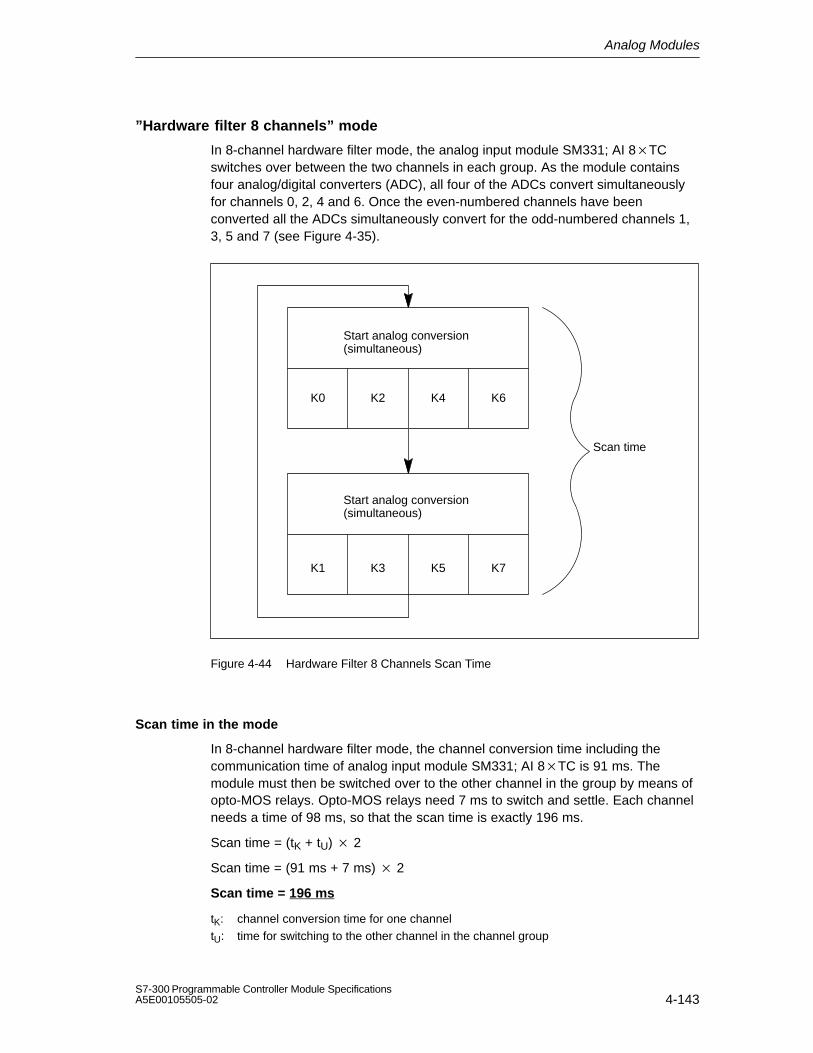
Analog Modules
4-143S7-300 Programmable Controller Module SpecificationsA5E00105505-02
”Hardware filter 8 channels” mode
In 8-channel hardware filter mode, the analog input module SM331; AI 8TCswitches over between the two channels in each group. As the module containsfour analog/digital converters (ADC), all four of the ADCs convert simultaneouslyfor channels 0, 2, 4 and 6. Once the even-numbered channels have beenconverted all the ADCs simultaneously convert for the odd-numbered channels 1,3, 5 and 7 (see Figure 4-35).
Scan time
Start analog conversion(simultaneous)
K0 K2 K4 K6
K1 K3 K5 K7
Start analog conversion(simultaneous)
Figure 4-44 Hardware Filter 8 Channels Scan Time
Scan time in the mode
In 8-channel hardware filter mode, the channel conversion time including thecommunication time of analog input module SM331; AI 8TC is 91 ms. Themodule must then be switched over to the other channel in the group by means ofopto-MOS relays. Opto-MOS relays need 7 ms to switch and settle. Each channelneeds a time of 98 ms, so that the scan time is exactly 196 ms.
Scan time = (tK + tU) 2
Scan time = (91 ms + 7 ms) 2
Scan time = 196 ms
tK: channel conversion time for one channeltU: time for switching to the other channel in the channel group

Analog Modules
4-144S7-300 Programmable Controller Module Specifications
A5E00105505-02
”Software filter 8 channels” mode
In 8-channel software filter mode, the analog input module SM331; AI 8TCswitches over between the two channels in each group. As the module containsfour analog/digital converters (ADC), all four of the ADCs convert simultaneouslyfor channels 0, 2, 4 and 6. Once the even-numbered channels have beenconverted all the ADCs simultaneously convert for the odd-numbered channels 1,3, 5 and 7 (see Figure 4-45).
Scan time
Start analog conversion(simultaneous)
K0 K2 K4 K6
K1 K3 K5 K7
Start analog conversion(simultaneous)
Figure 4-45 Software Filter 8 Channels Scan Time

Analog Modules
4-145S7-300 Programmable Controller Module SpecificationsA5E00105505-02
Scan time of the module
In the 8-channel software filter mode of analog input module SM331; AI 8TC, thechannel conversion time is guided by the interference frequency set. When you setan interference frequency of 50 Hz, the channel conversion time includingcommunication time is 76 ms. When you set an interference frequency of 60 Hz,the channel conversion time is 65 ms. When you set an interference frequency of400 Hz, the channel conversion time is reduced to 16 ms. As with 8-channelhardware filter mode, the module must be switched over by means of opto MOSrelays with a switchover time of 7 ms to the other channel of the group. Table 4-71shows the scan time of the module at a certain interference frequency.
Table 4-71 Scan Times in ”Software Filter, 8 Channels” Mode
Programmed interference frequency
suppression
Channel scan time* Module scan time (all channels)
50 Hz 83 ms 166 ms
60 Hz 72 ms 144 ms
400 Hz 23 ms 46 ms
* Channel scan time = channel conversion time + 7 ms switching time to the other channelin the channel group
”Hardware filter 4 channels” mode
In 4-channel hardware filter mode, the analog input module SM331; AI 8TC doesnot switch over between the channels of the individual groups. As the modulecontains four analog/digital converters (ADC), all four of the ADCs convertsimultaneously for channels 0, 2, 4 and 6.
Scan time
Start analog conversion(simultaneous)
K0 K2 K4 K6
Figure 4-46 Hardware Filter 4 Channels Scan Time

Analog Modules
4-146S7-300 Programmable Controller Module Specifications
A5E00105505-02
Scan time of the module
In 4-channel hardware filter mode, the channel conversion time including thecommunication time of analog input module SM331; AI 8TC is 10 ms. As themodule does not switch over between the channels in a group, the channel scantime and the module scan time are the same: 10 ms.
Channel conversion time = channel scan time = module scan time = 10 ms
Prolongation of the scan time with a wire-break check
The wire-break check is a software function of the module that is available in alloperating modes.
In the 8-channel hardware and software filter operating mode prolongs thescan time of the module by 4 ms, irrespective of the number of channels for whichwire-break has been enabled.
In the 4-channel hardware filter operating mode, the module interruptsprocessing of the input data 170 ms and performs a wire-break check. In otherwords, each wire-break check prolongs the scan time of the module by 93 ms.
Smoothing of the measured values
You fill find information that is generally applicable to the smoothing of analogvalues in Section 4.6.
Special characteristic with short-circuit to M or L
If you short an input channel to M or L, the module does not suffer any damage.The channel continues to issue valid data; neither is a diagnosis reported.
Diagnostics
You will find the diagnostic messages that are grouped under the ”group diagnosis”parameter in Table 4-46, on page 4-78.

Analog Modules
4-147S7-300 Programmable Controller Module SpecificationsA5E00105505-02
4.23.2 Measuring Methods and Measuring Ranges of the SM 331;AI 8 TC
Measuring methods
You can set the following measuring methods for the input channels:
Thermocouple, linearization with reference temperature 0 °C
Thermocouple, linearization with reference temperature 50 °C
Thermocouples, linearization with internal comparison
Thermocouple, linearization with external comparison
You perform the setting with the ”measuring method” parameter in STEP 7.
Unused channels
Set the ”measuring method” parameter for unused channels to ”disabled”. In thisway you shorten the scan time of the module.
You must terminate an unused channel in an enabled channel group to avoiddiagnostic errors for the unused channel. To do this, short the Plus input and Minusinput of the channel.
In the ”4-Channel Hardware Filter” operating mode, termination is not necessaryprovided that you have disabled the unused channel groups. Channels 1, 3, 5 and7 are not monitored in this mode.
Measuring ranges
You perform setting of the measuring ranges with the ”measuring range” parameterin STEP 7.
Table 4-72 Measuring Ranges of the SM 331;AI 8 TC
Method Selected Measuring Range Description
TC-L00C: (thermocouple, linear, referencetemperature 0 °C)
TC-L50C: (thermocouple, linear, referencetemperature 50 °C)
TC-IL:(thermocouple, linear, internalcompensation)
TC-EL:(thermocouple, linear, externalcompensation)
Type B
Type C
Type E
Type J
Type K
Type L
Type N
Type R
Type S
Type T
Type U
You will find the digitized analogvalues in Section 4.3.1 in thetemperature range

Analog Modules
4-148S7-300 Programmable Controller Module Specifications
A5E00105505-02
Special characteristic of parameter assignment to upper and lower limit values
The parameterizable limit values (triggers for hardware interrupt) differ for the AI 8 TC from the range of values shown in Table 4-69.
The reason for this is that numerical methods in the module software for evaluatingthe process variables prevent values up to 32511 from being reported in somecases. The process input value at which a hardware interrupt for an underflow oroverflow occurs depends on the calibration factors for an individual channel andcan vary between the lower limits shown in the Table below and 32511 (7EFFH).
Limit values should not be set at values higher than the minimum potential limitvalues shown in the tables below.
Table 4-73 Minimum Possible Upper and Lower Limit Values of SM 331; AI 8 x TC in in °C
Thermo-couple
Minimum Possible Upper Limit Value
Minimum Possible Lower Limit Value
in °C Dec. Hex. in °C Dec. Hex.
Type B 1820.1 18201 471AH 0 0 0
Type C --- --- --- --- --- ---
Type E --- --- --- --- --- ---
Type J 1200.1 12001 2EE1H <-210.0 <-2100 < F7CCH
Type K 1372.1 13721 3599H <-270.0 <-2700 < F574H
Type L 900.1 9001 2329H <-200.0 <-2000 < F830H
Type N --- --- --- --- --- ---
Type R, S 1769.1 1769.1 451BH -50.1 -501 FE0BH
Type T 400.1 4001 0FA1H <-270.0 <-2700 < F574H
Type U 600.1 6001 1771H <-200.0 <-2000 < F830H

Analog Modules
4-149S7-300 Programmable Controller Module SpecificationsA5E00105505-02
Table 4-74 Minimum Possible Upper and Lower Limit Values of SM 331; AI 8 x TC in in °F
Thermo-couple
Minimum Possible Upper Limit Value
Minimum Possible Lower Limit Value
in °F Dec. Hex. in °F Dec. Hex.
Type B 2786.6 27866 6CDAH 0 0 0
Type C --- --- --- --- --- ---
Type E --- --- -- --- --- --
Type J 2192.2 21922 55A2H <-346.0 <-3460 < F27CH
Type K 2501.8 25018 61BAH <454.0 <-4540 <EE44H
Type L 1652.2 16522 408AH <-328.0 <-3280 F330H
Type N --- --- --- --- --- ---
Type R, S 3216.4 3216.4 7DA4H -58.2 -582 FDBAH
Type T 752.2 7522 1062H <454.0 <-4540 <EE44H
Type U 1112.2 11122 2B72H <-328.0 <-3280 < F330H
End-of-scan-cycle interrupt
By enabling the end-of-scan-cycle interrupt, you can synchronize a process withthe conversion cycle of the module. The interrupt occurs when the conversion of allthe enabled channels is complete.
Table 4-75 Content of the 4 Bytes with Additional Information from OB40 during a HardwareInterrupt or an End-of-Scan-Cycle Interrupt
Content of the 4 bytes withadditional information
27 26 25 24 23 22 21 20 Byte
Analog 2 bits per channel to identify the rangespecialmark-
Upper limit exceeded inchannel
7 6 5 4 3 2 1 0 0ers
Lower limit exceeded inchannel
7 6 5 4 3 2 1 0 1
End-of-scan-cycle event X 2
Unassigned byte 3

Analog Modules
4-150S7-300 Programmable Controller Module Specifications
A5E00105505-02
4.24 Analog Input Module SM 331; AI 212 bits;(6ES7 331-7KBx2-0AB0)
Order number: ”Standard module”
6ES7 331-7KB02-0AB0
Order number: ”SIMATIC Outdoor module”
6ES7 331-7KB82-0AB0
Characteristics
The analog input module SM 331; AI 212 bits has the following characteristicfeatures:
Two inputs in one channel group
Measured-value resolution (depending on the integration time set)
– 9 bits + sign
– 12 bits + sign
– 14 bits + sign
Measuring method selectable per channel group:
– Voltage
– Current
– Resistors
– Temperature
Arbitrary measuring range selection per channel group
Programmable diagnostics
Programmable diagnostic interrupt
One channel with limit monitoring
Programmable hardware interrupt when limit has been exceeded
Isolated against the backplane bus interface
Isolated against load voltage (except when at least one coding key is inserted in position D)

Analog Modules
4-151S7-300 Programmable Controller Module SpecificationsA5E00105505-02
Resolution
The resolution of the measured value is a direct function of the integration timeselected. In other words the longer the integration time for an analog input channel,the more accurate the resolution of the measured value will be (see TechnicalSpecifications of the module and Table 4-6 on page 4-11).
Terminal connection diagram and block diagram of the SM 331; AI 212 bits
Fault indicator – red
Thermocouples,Voltage measurementCurrent measurement
Resistance test
M0 +
M0
M1 +
SF Internal supply
L+Current source
Multi-plexer
Meas. rangemodule
None
ADC
Isolation
Backplane businterface
SF
+
Internalcompensation
CH0 M0 + CH0M0IC0 +CH1
M1 IC0
24V
Comp–/ Mana
Comp +External compensation
Comp
M
T
Figure 4-47 Module View and Block Diagram of the Analog Input Module SM 331; AI 212 bits
The input resistances depend on the measuring range selected (refer to thetechnical specifications for the module).

Analog Modules
4-152S7-300 Programmable Controller Module Specifications
A5E00105505-02
Technical specifications of the SM 331; AI 212 bits
Dimensions and Weight
Dimensions W H D (in millimeters)
40 125 117
Weight Approx. 250 g
Data for Specific Module
Supports clocked operation No
Number of inputs
For resistance-typesensor
2
1
Length of cable
Shielded
max. 200 m
max. 50 m at 80 mV andthermocouples
Voltages, Currents, Potentials
Rated supply voltage of theelectronics L +
24 VDC
Reverse polarityprotection
Yes
Power supply of thetransmitters
Supply current max. 60 mA (per channel)
Short-circuit-proof Yes
Constant current forresistance-type sensor
typ. 1.67 mA
Isolation
Between channels andbackplane bus
Yes
Between channels andpower supply of theelectronics
Yes
Permitted potentialdifference
Between inputs andMANA (UCM)
– At signal = 0 V
– Not for 2-wiretransmitter
2.5 VDC
Between MANA andMinternal (UISO)
75 VDC / 60 VAC
Insulation tested with 500 VDC
Current consumption
From the backplane bus max. 50 mA
From the backplane busL +
max. 30 mA (withouttwo-wire transmitter)
Power dissipation of themodule
typ. 1.3 W
Analog Value Generation
Measuring principle Integrating
Integration time/conversiontime/ resolution (perchannel)
Parameters can beassigned
Yes
Integration time inmilliseconds
2.5 162/3 20 100
Basic conversion timeincluding Integrationtime in milliseconds
3 17 22 102
Additional conversiontime for measuringresistance, in msor
1 1 1 1
Additional conversiontime for open-circuitmonitoring, in msor
10 10 10 10
Additional conversiontime for measuringresistance andopen-circuit monitoring,in ms
16 16 16 16
Resolution in bits (incl.overrange)
9bits
12 bits
12bits
14 bits
Noise suppression forfrequency f1 in Hz
400 60 50 10
Basic execution time ofthe module, in ms (allchannels enabled)
6 34 44 204
Smoothing of the measuredvalues
None

Analog Modules
4-153S7-300 Programmable Controller Module SpecificationsA5E00105505-02
Suppression of interference, Limits of Error
Noise suppression for f = n (f1 1 %),(f1 = interference frequency) n=1.2...
Common-modeinterference(UCM < 2.5 V)
> 70 dB
Series-mode noise(peak value ofnoise < nominal value ofinput range)
> 40 dB
Crosstalk between theinputs
> 50 dB
Operational limit (in the entire temperature range, withreference to the input range)
Voltage input 80 mV 1 %
250 to1000mV
0.6 %
2.5 to 10 V 0.8 %
Current input 3.2 to 20 mA 0.7 %
Resistors 150Ω; 300Ω; 600 Ω
0, 7 %
Thermocouple Type E, N, J,K, L
1, 1 %
Resistance thermometer
Pt 100/Ni 100
0, 7 %
Pt 100climate
0, 8 %
Basic error (operational limit at 25 C referred to inputrange)
Voltage input 80 mV 0.6 %
250 to1000mV
0.4 %
2.5 to 10 V 0.6 %
Current input 3.2 to 20 mA 0.5 %
Resistors 150Ω; 300Ω; 600 Ω
0.5 %
Thermocouple Type E, N, J,K, L
0.7 %
Resistance thermometer
Pt 100/Ni 100
0.5 %
Pt 100climate
0.6 %
Temperature error (withreference to the input range)
0.005 %/K
Linearity error (withreference to the input range)
0.05 %
Repeatability (in steadystate at 25 C referred toinput range)
0.05 %
Temperature error of internalcompensation
1 %
Status, Interrupts, Diagnostics
Interrupts
Hardware interruptwhen limit has beenexceeded
Programmablechannel 0
Diagnostic Interrupt Programmable
Diagnostic functions
Group error display
Diagnostics informationread-out
Programmable
Red LED (SF)
Possible
Data for Selecting a Sensor
Input range (ratedvalues)/Input resistance
Voltage 80 mV
250 mV
500 mV
1000 mV
2.5 V
5 V
1 to 5 V;
10 V
/10 MΩ/10 MΩ/10 MΩ/10 MΩ/100kΩ/100kΩ/100kΩ/100kΩ
Current 3.2 mA
10 mA
20 mA
0 to 20 mA;
4 to 20 mA:
/25 Ω/25 Ω/25 Ω/25 Ω/25 Ω
Resistors 150 Ω300 Ω600 Ω
/10 ΜΩ/10 ΜΩ/10 ΜΩ
Thermocouples Type E, N, J,K, L
/10 ΜΩ
Resistance thermometer
Pt 100,Ni 100
/10 ΜΩ
Maximum input voltage forvoltage input (destructionlimit)
max. 20 V continuous; 75 V for max. 1 s(duty factor 1:20)
Maximum input current forcurrent input (destructionlimit)
40 mA

Analog Modules
4-154S7-300 Programmable Controller Module Specifications
A5E00105505-02
Connection of the sensor
For measuring voltage Possible
For measuring current
As two-wire transmitter
As four-wire transmitter
Possible
Possible
For measuringresistance
With two-conductorconnection
With three-conductorconnection
With four-conductorconnection
Possible
Possible
Possible
Load of the two-wiretransmitter
max. 820 Ω
Characteristic linearization
For thermocouples
Parameters can beassigned
Type E, N, J, K, L
For RTD Pt 100 (standard, climate range)Ni 100 (standard, climate range)
Temperature compensation Parameters can beassigned
Internal temperaturecompensation
Possible
External temperaturecompensation withcompensating box
Possible
Compensation for 0 Ccomparison pointtemperature
Possible
Technical unit fortemperaturemeasurement
Degrees Celsius
4.24.1 Commissioning the SM 331; AI 212 bits
You set the mode of operation of the SM 331; AI 2 12 bits by means of ameasuring range module on the module and in STEP 7.
Measuring range module
If necessary, the measuring range module must be replugged to change themeasuring method and the measuring range. The steps you have to perform to dothis are described in detail in Section 4.4.
The corresponding table in Section 4.24.2 tells you which assignment you have toselect for which measuring method and measuring range. In addition, thenecessary settings are embossed on the module.
Default settings for measuring range module
The measuring range module is preset to ”B” (voltage; 10 V) when the moduleis supplied.
To use the following preset measuring methods and measuring ranges, you onlyhave to change the measuring range module to the corresponding setting.Parameter assignment in STEP 7 is not necessary.

Analog Modules
4-155S7-300 Programmable Controller Module SpecificationsA5E00105505-02
Table 4-76 Default Settings of the SM 331; AI 212 bits Using Measuring Range Module
Measuring Range ModuleSetting
Measuring Method Measuring Range
A Voltage 1000 mV
B Voltage 10 V
C Current,four-wire transmitter
4 to 20 mA
D Current,two-wire transmitter
4 to 20 mA
Parameter
You will find a description of the general procedure for assigning parameters toanalog modules in Section 4.7.
An overview of the parameters that you can set and their default settings areshown in the table below.
Table 4-77 Parameters of the SM 331; AI 2 12 bits
Parameter Value Range DefaultSettings
ParameterType
Scope
Enable Diagnostic interrupt Hardware interrupt
upon limit violation
Yes/noYes/no
NoNo
Dynamic Module
Trigger for hardwareinterrupt
Upper limit value
Lower limit value
32511 to –32512
–32512 to 32511
– Dynamic Channel
Diagnostics Group diagnostics
With wire-breakcheck
Yes/no
Yes/no
No
NoStatic
Channelgroup

Analog Modules
4-156S7-300 Programmable Controller Module Specifications
A5E00105505-02
Table 4-77 Parameters of the SM 331; AI 2 12 bits
Parameter ScopeParameterType
DefaultSettings
Value Range
Measurement Measuring method Deactivated
U Voltage4DMU Current (four-wire transmitter)2DMU Current (two-wire transmitter)R-4L Resistance (four-conductor
connection)RTD-4L Bulb resistor
(linear, four-conductor connection)
TC-I Thermocouple (internal comparison)
TC-E Thermocouple (external comparison)
TC-IL Thermocouple (linear, internal comparison)
TC-EL Thermocouple (linear, external comparison)
U
DynamicChannel orchannelgroup
Measuring range Refer to Section 4.24.2 for themeasuring ranges of the inputchannels that you can set.
10 V
Interferencesuppression
400 Hz; 60 Hz; 50 Hz; 10 Hz 50 Hz
Channel groups
The two channels of the analog input module SM 331; AI 212 bits are combinedto a channel group. You can only ever assign parameters to the channel group.
The SM 331; AI 212 bits has a measuring range module for the channel group 0.
Special characteristic of channel groups with resistance measurement
If you use the resistance measurement method, the analog input module has onlyone channel. The ”2nd” channel is used for current injection (IC).
The measured value is obtained by accessing the ”1st” channel. The ”2nd” channelhas the default carry value ”7FFFH”.
Special characteristic of channel groups for hardware interrupts
You can set a hardware interrupt in STEP 7 for the channel group. Note, however,that a hardware interrupt is set only for the first channel in the channel group ineach case – in other words, for channel 0.

Analog Modules
4-157S7-300 Programmable Controller Module SpecificationsA5E00105505-02
Diagnostics
You will find the diagnostic messages that are grouped under the ”group diagnosis”parameter in Table 4-46, on page 4-78.
4.24.2 Measuring Methods and Measuring Ranges of the SM 331;AI 212 bits
Measuring methods
You can set the following measuring methods for the input channels:
Voltage measurement
Current measurement
Resistance test
Temperature measurement
You perform the setting by means of the measuring range module on the moduleand with the ”measuring method” parameter in STEP 7.
Unused channels
You must short-circuit unused channels and connect them to MANA. In this way,you obtain an optimum interference immunity for the analog input module. Set the”measuring method” parameter for unused channels to ”disabled”. In this way youshorten the scan time of the module.
If you do not use the COMP input, you must short-circuit it also.

Analog Modules
4-158S7-300 Programmable Controller Module Specifications
A5E00105505-02
Special characteristics of unused channels for some measuring ranges
Since configured inputs can remain unused because of the channel groupgeneration, you must take note of the following special characteristics of theseinputs to enable the diagnostic functions on the used channels.
Measuring range 1 to 5 V: Connect the unused input in parallel with a usedinput of the same channel group.
Current measurement, two-wire transmitter:There are two ways to use the channels:
a) Leave the unused input open and do not enable diagnostics for this channel group. Otherwise, if diagnostics are enabled, the analog module triggers a single diagnostic interrupt and the SF LED of the analog module comes on.
b) Connect the unused input with a resistance of 1.5 to 3.3 k You may then enable diagnostics for this channel group.
Current measurement 4 to 20 mA, four-wire transmitter: Connect theunused input in series with an input of the same channel group.
Measuring ranges
You perform the setting of the measuring ranges by means of the measuring rangemodule on the module and with the ”measuring method” parameter in STEP 7.
Table 4-78 Measuring Ranges of the SM 331; AI 2 x 12 bits
Method Selected Measuring Range (Type of Sensor)
Measuring RangeModule Setting
Description
U: Voltage 80 mV
250 mV
500 mV
1000 mV
A You will find the digitized analogvalues in Section 4.3.1 in thevoltage measuring range
2.5 V
5 V
1 to 5 V
10 V
B
TC-I: Thermocouple
(internal compensation)(thermovoltagemeasurement)
Type N [NiCrSi-NiSi]Type E [NiCr-CuNi]Type J [Fe-CuNi]
[ ]
A You will find the digitized analogvalues in Section 4.3.1 in 80 mVthe voltage measuring range
TC-E: Thermocouples
(external compensation) (thermovoltagemeasurement)
Type K [NiCr-Ni]Type L [Fe-CuNi]

Analog Modules
4-159S7-300 Programmable Controller Module SpecificationsA5E00105505-02
Table 4-78 Measuring Ranges of the SM 331; AI 2 x 12 bits
Method Selected DescriptionMeasuring RangeModule Setting
Measuring Range (Type of Sensor)
2DMU: Current (2-wiretransmitter)
4 to 20 mA D You will find the digitized analogvalues in Section 4.3.1 in the
4DMU: Current (4-wiretransmitter)
3.2 mA
10 mA
0 to 20 mA
4 to 20 mA
20 mA
Ccurrent measuring range
R-4L: Resistors
(four-conductor connection)
150
300
600
A You will find the digitized analogvalues in Section 4.3.1 in theresistance measuring range
TC-IL: Thermocouples(linear, internalcompensation)(temperature measurement)
Type N [NiCrSi-NiSi]Type E [NiCr-CuNi]Type J [Fe-CuNi]Type K [NiCr-Ni]Type L [Fe-CuNi]
A You will find the digitized analogvalues in Section 4.3.1 in thetemperature range
The characteristics are linearized:
Pt 100 to DIN IEC 751
TC-EL: Thermocouples
(linear, externalcompensation)(temperature measurement)
Type N [NiCrSi-NiSi]Type E [NiCr-CuNi]Type J [Fe-CuNi]Type K [NiCr-Ni]Type L [Fe-CuNi]
A Ni 100 according to IEC DIN
43760
Thermocouple to DIN 584,type L to DIN 43710.
RTD-4L: Bulb resistor
(linear, four-conductorconnection), (temperature measurement)
Pt 100 climate
Ni 100 climate
Pt 100 standard
Ni 100 standard
A
Default settings
The default settings of the module in STEP 7 are the ”voltage” measuring methodund the ” 10 V” measuring range. You can use this combination of measuringmethod and measuring range without parameterizing the SM 331; AI 8 12 bits inSTEP 7.
Wire-break check
The wire-break check is intended primarily for temperature measurements(thermocouples and bulb resistors).

Analog Modules
4-160S7-300 Programmable Controller Module Specifications
A5E00105505-02
Special characteristics of the wire-break check for the 4 to 20 mA measuringrange
With a parameterized measuring range of 4 to 20 mA and enabled wire-breakcheck, the analog input module enters wire-break in the diagnosis when a currentfalls below 3.6 mA.
If you have enabled diagnostics interrupt during configuration, the moduleadditionally triggers a diagnostic interrupt.
If no diagnostic interrupt has been enabled, the illuminated SF LED is the onlyindication of the wire-break and you must evaluate the diagnostic bytes in the userprogram.
With a parameterized measuring range of 4 to 20 mA and disabled wire-breakcheck and enabled diagnostic interrupt, the module triggers a diagnostic interruptwhen the underflow is reached.
4.25 Analog Output Module SM 332; AO 8 12 bits; (6ES7 332-5HF00-0AB0)
Order number
6ES7 332-5HF00-0AB0
Characteristics
The analog input module SM 332; AO 8 × 12 bits has the following characteristicfeatures
8 outputs in 8 channel groups
The individual output channels can be programmed as
– Voltage outputs
– Current outputs
Resolution 12 bits
Programmable diagnostics
Programmable diagnostic interrupt
Isolated against backplane bus interface and load voltage

Analog Modules
4-161S7-300 Programmable Controller Module SpecificationsA5E00105505-02
Terminal connection and block diagram of analog output module SM 332; AO 8 12 bits
Isolation
Backplane businterface
DAC
Voltage outputs
DAC
Current outputs
Voltage outputs
Current outputsFault indicator – red
Internal supply
Figure 4-48 Module View and Block Diagram of the Analog Output Module SM 332; AO 8 12 bits

Analog Modules
4-162S7-300 Programmable Controller Module Specifications
A5E00105505-02
Technical specifications of the SM 332; AO 8 12 bits
Dimensions and Weight
Dimensions W × H × D (in millimeters)
40 × 125 × 117
Weight Approx. 272 g
Data for Specific Module
Supports clocked operation
No
Number of inputs 8
Length of cable
Shielded max. 200 m
Voltages, Currents, Potentials
Rated load voltage L+
Reverse polarity protection
Isolation
Between channels andbackplane bus
Between channels andpower supply of theelectronics
Between the channels
Between channels and loadvoltage L+
Permitted potential difference
Between S– and MANA(UCM)
Between MANA andMinternal (UISO)
24 VDC
Yes
Yes
Yes
No
Yes
3 VDC
75 VDC / 60 VAC
Insulation tested with 500 VDC
Current consumption
From the backplane bus max. 100 mA
From supply voltage L+ (noload)
max. 340 mA
Power dissipation of the module typically 6.0 W
Analog Value Generation
Resolution including sign
± 10 V; ± 20 mA; 4 to 20 mA; 1 to 5 V
0 to 10 V; 0 to 20 mA;
Conversion time (per channel)
Settling time
For resistive load
For capacitive load
For inductive load
11 bits + sign
12 bitsmax. 0.8 ms
0.2 ms
3.3 ms
0.5 ms (1 mH)
3.3 ms (10 mH)
Suppression of Interference, Limits of Error
Crosstalk between theoutputs
> 40 dB
Operational limit (in the entire temperature range, withreference to the output range)
Voltage outputs ±0.5 %
Current outputs ±0.6 %
Basic error (operational limit at 25 °C referred to theoutput range)
Output voltage
Output current
± 0.4 %
± 0.5 %
Temperature error (withreference to the outputrange)
±0.002 % /K
Linearity error (withreference to the outputrange)
+ 0.05 %
Repeat accuracy (in thesteady state at 25°C,referred to the outputrange)
±0.05 %
Output ripple; bandwidth 0 to 50 kHz (withreference to the outputrange)
± 0.05 %
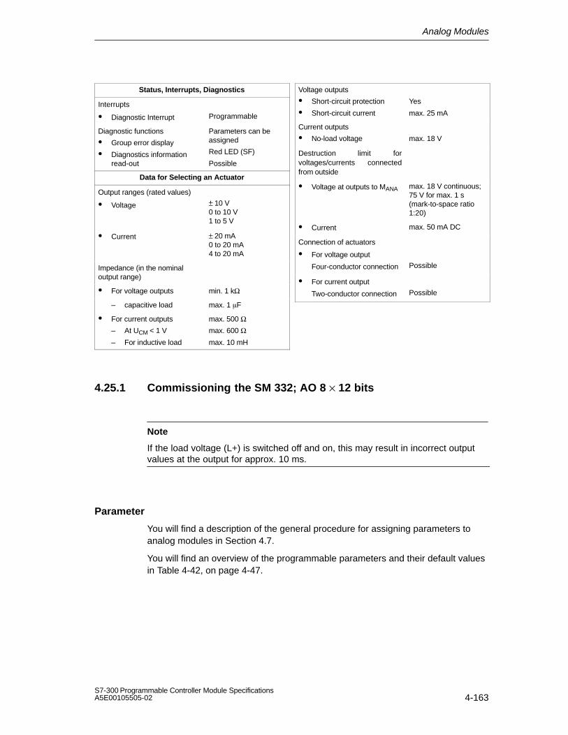
Analog Modules
4-163S7-300 Programmable Controller Module SpecificationsA5E00105505-02
Status, Interrupts, Diagnostics
Interrupts
Diagnostic Interrupt Programmable
Diagnostic functions
Group error display
Diagnostics informationread-out
Parameters can beassigned
Red LED (SF)
Possible
Data for Selecting an Actuator
Output ranges (rated values)
± Voltage ± 10 V0 to 10 V1 to 5 V
Current ± 20 mA0 to 20 mA4 to 20 mA
Impedance (in the nominaloutput range)
For voltage outputs min. 1 kΩ
– capacitive load max. 1 F
For current outputs
– At UCM < 1 V
– For inductive load
max. 500 Ωmax. 600 Ωmax. 10 mH
Voltage outputs
Short-circuit protection
Short-circuit current
Yes
max. 25 mA
Current outputs
No-load voltage max. 18 V
Destruction limit forvoltages/currents connectedfrom outside
Voltage at outputs to MANA max. 18 V continuous; 75 V for max. 1 s (mark-to-space ratio1:20)
Current max. 50 mA DC
Connection of actuators
For voltage output
Four-conductor connection Possible
For current output
Two-conductor connection Possible
4.25.1 Commissioning the SM 332; AO 8 × 12 bits
Note
If the load voltage (L+) is switched off and on, this may result in incorrect outputvalues at the output for approx. 10 ms.
Parameter
You will find a description of the general procedure for assigning parameters toanalog modules in Section 4.7.
You will find an overview of the programmable parameters and their default valuesin Table 4-42, on page 4-47.

Analog Modules
4-164S7-300 Programmable Controller Module Specifications
A5E00105505-02
Assigning parameters to channels
You can configure each output channel of the SM 332; AO 8 12 bits individually.You can thus assign separate parameters for each output channel.
When you set the parameters with SFCs in the user program, the parameters areassigned to channel groups. Every output channel of the SM 332; AO 8 12 bitsis assigned to a channel group in this instance – in other words, for example outputchannel 0 = channel group0.
Note
If you modify output ranges when the analog output module SM 332; AO 8 12bits is in operation, incorrect intermediate values may arise across the output.
Diagnostics
You will find the diagnostic messages that are grouped under the ”group diagnosis”parameter in Table 4-47, on page 4-79.
4.25.2 Output Ranges of the Analog Output Module SM 332;AO 8 12 bits
Connecting the analog outputs
You can connect the outputs as voltage or current outputs, or disable them. Youperform connection of the outputs with the ”output type” parameter in STEP 7.
Unused channels
So that unused output channels of the SM 332; AO 8 12 bits remainde-energized, you must set the ”output type” parameter to ”disabled” and leave theterminal open.

Analog Modules
4-165S7-300 Programmable Controller Module SpecificationsA5E00105505-02
Output ranges
You program the output ranges for voltage and current outputs in STEP 7.
Table 4-79 Output Ranges of the Analog Output Module der SM 332; AO 8 12 bits
Selected Type of Output Output Range Description
Voltage 1 to 5 V0 to 10 V 10 V
You will find the digitalanalog values in Section4.3.2 in the voltage and
Current 0 to 20 mA4 to 20 mA 20 mA
current output ranges
Default settings
The default settings of the module are ”Voltage” for the output type and ”10 V”for the output range. You can use this combination of output type and output rangewithout parameterizing the SM 332; AO 8 12 bits in STEP 7.
Wire-break check
The analog output module SM 332; AO 8 12 bits carries out a wire-break checkonly for current outputs.
Short-circuit test
The analog output module SM 332; AO 8 12 bits carries out a short-circuit testonly for voltage outputs.

Analog Modules
4-166S7-300 Programmable Controller Module Specifications
A5E00105505-02
4.26 Analog Output Module SM 332; AO 4 16 bits;(6ES7 332-7ND01-0AB0)
Order number
6ES7 332-7ND01-0AB0
Characteristics
The analog output module SM 332; AO 4 16 bits has the following characteristicfeatures:
4 outputs in 4 channel groups
The individual output channels can be programmed as
– Voltage outputs
– Current outputs
Resolution of 16 bits
Supports clocked operation
Programmable diagnostics
Programmable diagnostic interrupt
Programmable substitute value output
Galvanic isolation between:
– Backplane bus interface and analog output channel
– The different analog output channels
– Analog output and L+, M
– Backplane bus interface and L+, M

Analog Modules
4-167S7-300 Programmable Controller Module SpecificationsA5E00105505-02
Terminal connection and block diagram of analog output moduleSM 332; AO 4 16 bits
SF
QI0Isolation
CH0 CH0
CurrentOutputs
VoltageOutputs
MANA 0
QV0
S 0+
S 0 –
MANA 0
Fault indicator – red
QI1
CH1 CH1
MANA 1
QV1
S 1 +
S 1 –
MANA 1
QI2
CH2 CH2
MANA 2
QV2
S 2 +
S 2 –
MANA 2
QI3
CH3 CH3
MANA 3
QV3
S 3 +
S 3 –
MANA 3
L+24 V
M
1
3
4
5
6
7
8
9
10
11
12
13
14
15
16
17
18
20
Back-planebus IM
Figure 4-49 Module View and Block Diagram of the SM 332; AO 4 x 16 bits

Analog Modules
4-168S7-300 Programmable Controller Module Specifications
A5E00105505-02
Technical specifications of the SM 332; AO 4 16 bits
Dimensions and Weight
Dimensions W H D (in millimeters)
40 125 117
Weight Approx. 220 g
Data for Specific Module
Supports clocked operation
Yes
Number of outputs 4
Length of cable
Shielded max. 200 m
Voltages, Currents, and Potentials
Rated load voltage L+
Reverse polarity protection
24 VDC
Yes
Isolation
Between channels andbackplane bus
Yes
Between channels andpower supply of theelectronics
Yes
Between the channels Yes
Between channels and loadvoltage L+
Yes
Permitted potential difference
Between the outputs (ECM) 200 VDC / 120 VAC
Between MANA andMinternal (UISO)
200 VDC / 120 VAC
Insulation tested with 500 VDC
Current consumption
From the backplane bus max. 60 mA
From the load voltage L+(no load)
max. 240 mA
Power dissipation of the module typ. 3 W
Analog Value Generation
Resolution (including overrange)
15 bits + sign
1 to 5 V 13 bits
4 to 20 mA 14 bits
Conversion time max. 1.5 ms
Settling time
For resistive load
For capacitive load
For inductive load
0.2 ms
1.0 ms
0.2 ms
Suppression of interference, Limits of Error
Crosstalk between outputs
> 100 dB
Operational limit (in the entire temperature range, withreference to the output range)
Voltage outputs ±0.12%
Current outputs ±0.18%
Basic error (operational limit at 25° C, referred to outputrange)
Voltage outputs ±0.02%
Current outputs ±0.02%
Temperature error (withreference to the output range)
±0.001%
Linearity error (with reference tothe output range)
±0.004%
Repeat accuracy (in the steadystate at 25° C, referred to theoutput range)
±0.002 %
Output ripple; band width 0 to50 kHz (with reference to theoutput range)
±0.05 %
Status, Interrupts, Diagnostics
Interrupts
Diagnostic Interrupt Programmable
Diagnostic functions Programmable
Group error display Red LED (SF)
Diagnostic information readable
Possible
Substitute value can be applied Yes, programmable

Analog Modules
4-169S7-300 Programmable Controller Module SpecificationsA5E00105505-02
Data for Selecting an Actuator
Output ranges (rated values)
Voltage ±10 V0 to 10 V1 to 5 V
Current ±20 mA0 to 20 mA4 to 20 mA
Load resistance (in the nominalrange of the output)
For voltage outputs
– Capacitive load
min. 1 kΩmax. 1 µF
For current outputs
– Inductive load
max. 500 Ωmax. 1 mH
Voltage outputs
Short-circuit protection
Short-circuit current
Yes
max. 40 mA
Current outputs
No-load voltage max. 18 V
Destruction limit againstvoltages/currents applied fromoutside
Voltage at outputs to MANA max. 15 V continuous
75 VDC for no more than0.1 s (pulse duty factor 1 : 20)
Current max. 50 mA DC
Connection of actuators
For voltage output
– Four-conductorconnection (measuringcircuit)
Possible
For current output
– Two-conductorconnection
Possible
4.26.1 Commissioning the SM 332; AO 4 16 bits
Parameter
You will find a description of the general procedure for assigning parameters toanalog modules in Section 4.7.
You will find an overview of the programmable parameters and their default valuesin Table 4-42, on page 4-47.
Assigning parameters to channels
You can configure each output channel of the SM 332; AO 4 16 bits individually.You can thus assign separate parameters for each output channel.
When you set the parameters with SFCs in the user program, the parameters areassigned to channel groups. Every output channel of the SM 332; AO 4 16 bits isassigned to a channel group in this instance – in other words, for example outputchannel 0 = channel group0.
Note
If you modify output ranges when the analog output module SM 332; AO 4 16bits is in operation, incorrect intermediate values may arise across the output.

Analog Modules
4-170S7-300 Programmable Controller Module Specifications
A5E00105505-02
Diagnostics
You will find the diagnostic messages that are grouped under the ”group diagnosis”parameter in Table 4-47, on page 4-79.
4.26.2 Output Ranges of the Analog Output Module SM 332; AO 416 bits
Connecting the analog outputs
You can connect the outputs as voltage or current outputs, or disable them. Youperform connection of the outputs with the ”output type” parameter in STEP 7.
Unused channels
So that unused output channels of the SM 332; AO 4 16 bits remainde-energized, you must set the ”output type” parameter to ”disabled” and leave theterminal open.
Output ranges
You program the output ranges for voltage and current outputs in STEP 7.
Table 4-80 Output Ranges of the Analog Output Module SM 332; AO 416 bits
Selected Type of Output Output Range Description
Voltage 1 to 5 V0 to 10 V 10 V
You will find the digitalanalog values in Section4.3.2 in the voltage and
Current 0 to 20 mA4 to 20 mA 20 mA
current output ranges
Default settings
The default settings of the module are ”Voltage” for the output type and ” 10 V”for the output range. You can use this combination of output type and output rangewithout parameterizing the SM 332; AO 4 16 bits in STEP 7.
Substitute values
You can configure the SM 332; AO 4 16 bits for the CPU operating mode STOPas follows: Outputs De-energized, Hold Last Value or Inject Substitute Values. Ifyou inject substitute values, they must be within the output range.

Analog Modules
4-171S7-300 Programmable Controller Module SpecificationsA5E00105505-02
4.27 Analog Output Module SM 332; AO 4 12 bits;(6ES7 332-5HD01-0AB0)
Order number
6ES7 332-5HD01-0AB0
Characteristics
The analog output module SM 332; AO 4 12 bits has the following characteristicfeatures:
4 outputs in 4 channel groups
The individual output channels can be programmed as
– Voltage outputs
– Current outputs
Resolution 12 bits
Programmable diagnostics
Programmable diagnostic interrupt
Programmable substitute value output
Isolated against backplane bus interface and load voltage

Analog Modules
4-172S7-300 Programmable Controller Module Specifications
A5E00105505-02
Terminal connection and block diagram of analog output module SM 332; AO 4 12 bits
Currentoutput
QI0
MANA
QI1
MANA
QI2
MANAQI3
MANA
CH0
CH1
CH2
CH3
Voltageoutputs
QV0
S0
S0 +
MANA
QV1
S1 +
S1
MANA
QV2S2 +
S2
MANAQV3
S3 +
S3
MANA
CH0
CH1
CH2
CH3
SF
Fault indicator – red
Internal supply
Isolation
Backplane businterface
SF
L +24VDAC
MM
Figure 4-50 Module View and Block Diagram of the Analog Output Module SM 332; AO 4 12 bits

Analog Modules
4-173S7-300 Programmable Controller Module SpecificationsA5E00105505-02
Technical specifications of the SM 332; AO 4 12 bits
Dimensions and Weight
Dimensions W H D (in millimeters)
40 125 117
Weight Approx. 220 g
Data for Specific Module
Supports clocked operation
No
Number of outputs 4
Length of cable
Shielded max. 200 m
Voltages, Currents, Potentials
Rated load voltage L +
Reverse polarity protection
24 VDC
Yes
Isolation
Between channels andbackplane bus
Yes
Between channels andpower supply of theelectronics
Yes
Between the channels No
Between channels and loadvoltage L+
Yes
Permitted potential difference
Between S– and MANA(UCM)
3 VDC
Between MANA andMinternal (UISO)
75 VDC / 60 VAC
Insulation tested with 500 VDC
Current consumption
From the backplane bus max. 60 mA
From the load voltage L+(no load)
max. 240 mA
Power dissipation of the module typ. 3 W
Analog Value Generation
Resolution including sign
10 V; 20 mA;4 to 20 mA; 1 to 5 V
11 bits + sign
0 to 10 V; 0 to 20 mA 12 bits
Conversion time (per channel) max. 0.8 ms
Settling time
For resistive load
For capacitive load
For inductive load
0.2 ms
3.3 ms
0.5 ms (1 mH)
3.3 ms (10 mH)
Suppression of Interference, Limits of Error
Crosstalk between the outputs > 40 dB
Operational limit (in the entire temperature range, withreference to the output range)
Voltage outputs
Current outputs
0.5 %
0.6 %
Basic error (operational limit at 25° C, referred to outputrange)
Voltage outputs
Current outputs
0.4 %
0.5 %
Temperature error (withreference to the output range)
0.002 %/K
Linearity error (with reference tothe output range)
0.05 %
Repeatability (in steady state at25 C, referred to output range)
0.05 %
Output ripple; range 0 to 50 kHz(referred to output range)
0.05 %
Status, Interrupts, Diagnostics
Interrupts
Diagnostic interrupt Parameters can beassigned
Diagnostic functions Programmable
Group error display Red LED (SF)
Diagnostic information readable
Possible
Substitute value can be applied Yes, programmable

Analog Modules
4-174S7-300 Programmable Controller Module Specifications
A5E00105505-02
Data for Selecting an Actuator
Output ranges (rated values)
Voltage ±10 V0 to 10 V1 to 5 V
Current ±20 mA0 to 20 mA4 to 20 mA
Load resistance (in the nominalrange of the output)
For voltage outputs
– Capacitive load
min. 1 kΩmax. 1 µF
For current outputs
– At UCM< 1V
– Inductive load
max. 500 Ωmax. 600
max. 10 mH
Voltage outputs
Short-circuit protection
Short-circuit current
Yes
max. 25 mA
Current outputs
No-load voltage max. 18 V
Destruction limit againstvoltages/currents applied fromoutside
Voltage at outputs to MANA max. 18 V continuous; 75 V for max. 1 s (dutyfactor 1:20)
Current max. 50 mA DC
Connection of actuators
For voltage output
– Four-conductorconnection (measuringcircuit)
Possible
For current output
– Two-conductorconnection
Possible
4.27.1 Commissioning the SM 332; AO 4 12 bits
Note
When switching on and off the rated load voltage (L+), wrong intermediate valuescan occur across the output for approximately 10 ms.
Parameter
You will find a description of the general procedure for assigning parameters toanalog modules in Section 4.7.
You will find an overview of the programmable parameters and their default valuesin Table 4-42, on page 4-47.

Analog Modules
4-175S7-300 Programmable Controller Module SpecificationsA5E00105505-02
Assigning parameters to channels
You can configure each output channel of the SM 332; AO 4 12 bits individually.You can thus assign separate parameters for each output channel.
When you set the parameters with SFCs in the user program, the parameters areassigned to channel groups. Every output channel of the SM 332; AO 4 12 bitsis assigned to a channel group in this instance – in other words, for example outputchannel 0 = channel group0.
Note
If you modify output ranges when the analog output module SM 332; AO 4 12bits is in operation, incorrect intermediate values may arise across the output.
Diagnostics
You will find the diagnostic messages that are grouped under the ”group diagnosis”parameter in Table 4-47, on page 4-79.
4.27.2 Output Ranges of the Analog Output Module SM 332;AO 4 12 bits
Connecting the analog outputs
You can connect the outputs as voltage or current outputs, or disable them. Youperform connection of the outputs with the ”output type” parameter in STEP 7.
Unused channels
So that unused output channels of the SM 332; AO 4 12 bits remainde-energized, you must set the ”output type” parameter to ”disabled” and leave theterminal open.

Analog Modules
4-176S7-300 Programmable Controller Module Specifications
A5E00105505-02
Output ranges
You program the output ranges for voltage and current outputs in STEP 7.
Table 4-81 Output Ranges of the Analog Output Module SM 332; AO 4 12 bits
Selected Type of Output Output Range Description
Voltage 1 to 5 V0 to 10 V 10 V
You will find the digitalanalog values in Section4.3.2 in the voltage and
Current 0 to 20 mA4 to 20 mA 20 mA
current output ranges
Default settings
The default settings of the module are ”Voltage” for the output type and ” 10 V”for the output range. You can use this combination of output type and output rangewithout parameterizing the SM 332; AO 4 12 bits in STEP 7.
Wire-break check
The analog output module SM 332; AO 4 12 bits carries out a wire-break checkonly for current outputs.
Short-circuit test
The analog output module SM 332; AO 4 12 bits carries out a short-circuit testonly for voltage outputs.
Substitute values
You can configure the SM 332; AO 4 12 bits for the CPU operating mode STOPas follows: Outputs De-energized, Hold Last Value or Inject Substitute Values. Ifyou inject substitute values, they must be within the output range.
Special characteristic of substitute values for output ranges 1 to 5 V and 4 to 20 mA
The following special characteristic applies to output ranges 1 to 5 V and 4 to20 mA:
You have to set the substitute value E500H for the output to become de-energized(refer to Tables 4-35 and 4-37 on pages 4-29 and 4-30).

Analog Modules
4-177S7-300 Programmable Controller Module SpecificationsA5E00105505-02
4.28 Analog Input/Output ModuleSM 332; AO 212 bits;(6ES7 332-5HBx1-0AB0)
Order number
6ES7 332-5HB01-0AB0
Order number: ”SIMATIC Outdoor module”
6ES7 332-5HB81-0AB0
Characteristics
The analog output module SM 332; AO 212 bits has the following characteristicfeatures:
2 output in 2 channels groups
The individual output channels can be programmed as
– Voltage outputs
– Current outputs
Resolution 12 bits
Programmable diagnostics
Programmable diagnostic interrupt
Programmable substitute value output
Isolated against backplane bus interface and load voltage

Analog Modules
4-178S7-300 Programmable Controller Module Specifications
A5E00105505-02
Terminal connection diagram and block diagram of the SM 332; AO 212 bits
Currentoutput
QI0
MANA
QI1
MANA
CH0
CH1
Voltageoutputs
QV0
S0
S0 +
MANA
QV1
S1 +
S1
MANA
CH0
CH1
SF
Fault indicator – red
Internal supply
Isolation
Backplane businterface
SF
L +24VDAC
MM
Figure 4-51 Module View and Block Diagram of the Analog Output Module SM 332; AO 212 bits

Analog Modules
4-179S7-300 Programmable Controller Module SpecificationsA5E00105505-02
Technical specifications of the SM 332; AO 212 bits
Dimensions and Weight
Dimensions W H D (in millimeters)
40 125 117
Weight Approx. 220 g
Data for Specific Module
Supports clocked operation
No
Number of outputs 2
Length of cable
Shielded max. 200 m
Voltages, Currents, Potentials
Rated load voltage L +
Reverse polarity protection
24 VDC
Yes
Isolation
Between channels andbackplane bus
Yes
Between channels andpower supply of theelectronics
Yes
Between the channels No
Between channels and loadvoltage L+
Yes
Permitted potential difference
Between S– and MANA(UCM)
3 VDC
Between MANA andMinternal (UISO)
75 VDC / 60 VAC
Insulation tested with 500 VDC
Current consumption
From the backplane bus max. 60 mA
From the load voltage L+(no load)
max. 135 mA
Power dissipation of the module typ. 3 W
Analog Value Generation
Resolution including sign
10 V; 20 mA;4 to 20 mA; 1 to 5 V
11 bits + sign
0 to 10 V; 0 to 20 mA 12 bits
Conversion time (per channel) max. 0.8 ms
Settling time
For resistive load
For capacitive load
For inductive load
0.2 ms
3.3 ms
0.5 ms (1 mH)
3.3 ms (10 mH)
Suppression of Interference, Limits of Error
Crosstalk between the outputs > 40 dB
Operational limit (in the entire temperature range, withreference to the output range)
Voltage outputs
Current outputs
0.5 %
0.6 %
Basic error (operational limit at 25° C, referred to outputrange)
Voltage outputs
Current outputs
0.4 %
0.5 %
Temperature error (withreference to the output range)
0.002 %/K
Linearity error (with reference tothe output range)
0.05 %
Repeatability (in steady state at25 C, referred to output range)
0.05 %
Output ripple; range 0 to 50 kHz(referred to output range)
0.05 %
Status, Interrupts, Diagnostics
Interrupts
Diagnostic Interrupt Parameters can beassigned
Diagnostic functions Programmable
Group error display Red LED (SF)
Diagnostic information readable
Possible
Substitute value can be applied Yes, programmable

Analog Modules
4-180S7-300 Programmable Controller Module Specifications
A5E00105505-02
Data for Selecting an Actuator
Output ranges (rated values)
Voltage ±10 V0 to 10 V1 to 5 V
Current ±20 mA0 to 20 mA4 to 20 mA
Load resistance (in the nominalrange of the output)
For voltage outputs
– Capacitive load
min. 1 kΩmax. 1 µF
For current outputs
– At UCM< 1V
– Inductive load
max. 500 Ωmax. 600
max. 10 mH
Voltage outputs
Short-circuit protection
Short-circuit current
Yes
max. 25 mA
Current outputs
No-load voltage max. 18 V
Destruction limit againstvoltages/currents applied fromoutside
Voltage at outputs to MANA max. 18 V continuous; 75 V for max. 1 s (dutyfactor 1:20)
Current max. 50 mA DC
Connection of actuators
For voltage output
– Two-conductorconnection
– Four-conductorconnection (measuring circuit)
Possible
Possible
For current output
– Two-conductorconnection
Possible
4.28.1 Commissioning the SM 332; AO 212 bits
Note
When switching on and off the rated load voltage (L+), wrong intermediate valuescan occur across the output for approximately 10 ms.
Parameter
You will find a description of the general procedure for assigning parameters toanalog modules in Section 4.7.
You will find an overview of the programmable parameters and their default valuesin Table 4-42, on page 4-47.

Analog Modules
4-181S7-300 Programmable Controller Module SpecificationsA5E00105505-02
Assigning parameters to channels
You can configure each output channel of the SM 332; AO 2 12 bits individually.You can thus assign separate parameters for each output channel.
When you set the parameters with SFCs in the user program, the parameters areassigned to channel groups. Every output channel of the SM 332; AO 2 12 bitsis assigned to a channel group in this instance – in other words, for example outputchannel 0 = channel group0.
Note
If you modify output ranges when the analog output module SM 332; AO 2 12 bits is in operation, incorrect intermediate values can arise across theoutput.
Diagnostics
You will find the diagnostic messages that are grouped under the “group diagnosis”parameter in Table 4-47, on page 4-79.
4.28.2 Output Ranges of the Analog Output Module SM 332; AO 212 bits
Connecting the analog outputs
You can connect the outputs as voltage or current outputs, or disable them. Youperform connection of the outputs with the ”output type” parameter in STEP 7.
Unused channels
So that unused output channels of the SM 332; AO 2 12 bits remainde-energized, you must set the ”output type” parameter to ”disabled” and leave theterminal open.

Analog Modules
4-182S7-300 Programmable Controller Module Specifications
A5E00105505-02
Output ranges
You program the output ranges for voltage and current outputs in STEP 7.
Table 4-82 Output Ranges of the Analog Output Module SM 332; AO 212 bits
Selected Type of Output Output Range Description
Voltage 1 to 5 V0 to 10 V 10 V
You will find the digitalanalog values inSection 4.3.2 in the voltage
Current 0 to 20 mA4 to 20 mA 20 mA
and current output ranges
Default settings
The default settings of the module are ”Voltage” for the output type and ” 10 V”for the output range. You can use this combination of output type and output rangewithout parameterizing the SM 332; AO 2 12 bits in STEP 7.
Wire-break check
The analog output module SM 332; AO 212 bits carries out a wire-break checkonly for current outputs.
Short-circuit test
The analog output module SM 332; AO 212 bits carries out a short-circuit checkonly for voltage outputs.
Substitute values
You can configure the SM 332; AO 2 12 bits for the CPU operating mode STOPas follows: Outputs De-energized, Hold Last Value or Inject Substitute Values. Ifyou inject substitute values, they must be within the output range.
Special characteristic of substitute values for output ranges 1 to 5 V and 4 to 20 mA
The following special characteristic applies to output ranges 1 to 5 V and 4 to 20 mA:
You have to set the substitute value E500H for the output to remain de-energized(refer to Tables 4-35 and 4-37 on pages 4-29 and 4-30).

Analog Modules
4-183S7-300 Programmable Controller Module SpecificationsA5E00105505-02
4.29 Analog Input/Output Module SM334;AI 4/AO 28/8 bits; (6ES7 334-0CE01-0AA0)
Order number
6ES7 334-0CE01-0AA0
Characteristics
The analog input/output module SM 334: AI 4/AO 2 8/8 bits has the followingcharacteristic features:
Four inputs, two outputs
Resolution 8 bits
Not parameterizable, setting of measurement and output type by means ofwiring
Measuring range of 0 to 10 V or 0 to 20 mA
Output range of 0 to 10 V or 0 to 20 mA
Both voltage and current output options
Non-isolated against the backplane bus interface
Isolated from load voltage

Analog Modules
4-184S7-300 Programmable Controller Module Specifications
A5E00105505-02
Module view and block diagram of the SM 334; AI 4/AO 2 8/8 bits
Select the measuring method of the input channels and the output type of theoutput channels via the wiring.
Internal supply
Backplane businterface
L +24V
DAC
MM
MV0 +
M0
MV1 +
MI0 +
M1
MI1 +
MV2 +
M2
MI2 +
MV3 +M3
MI3 +
CH0
CH1
CH2
CH3
QV0MANA
QI0QV1
MANA
QI1
CH0
CH1
ADC
Vol
tage
Cur
rent
out
puts
Vol
tage
Cur
rent
mea
sure
men
t
MANA
MANA
V
A
V
A
A
V
A
V
A
V
V
A
Figure 4-52 Module View and Block Diagram of the Analog Input/Output Module SM 334; AI 4/AO 2 8/8 bits

Analog Modules
4-185S7-300 Programmable Controller Module SpecificationsA5E00105505-02
Technical specifications of the SM 334; AI 4/AO 2 8/8 bits
Dimensions and Weight
Dimensions W H D (in millimeters)
40 125 117
Weight Approx. 285 g
Data for Specific Module
Supports clocked operation
No
Number of inputs 4
Number of outputs 2
Length of cable
Shielded max. 200 m
Voltages, Currents, Potentials
Rated load voltage L + 24 VDC
Power rated voltage of the ratedelectronics voltage and ratedload voltage L+
24 VDC
Isolation
Between channels andbackplane bus
No
Between channels andpower supply of theelectronics
Yes
Between the channels No
Permitted potential difference
Between inputs and MANA(UCM)
1 VDC
Between the inputs (ECM) 1 VDC
Insulation tested with 500 VDC
Current consumption
From the backplane bus max. 55 mA
From power supply andload voltage L+ (no load)
max. 110 mA
Power dissipation of the module typ. 3 W
Analog Value Generation for the Inputs
Measuring principle Instantaneous valueconversion
Integration/conversion time (perchannel)
Parameters can beassigned
No
Integration time inmilliseconds
500
Basic conversion timeincluding Integration time inmilliseconds
100
Resolution including sign 8 bits
Time constant of the input filter
max. 0.8 ms
Basic execution time of themodule (all channels enabled)
max. 5 ms
Analog Value Generation for the Outputs
Resolution including sign 8 bits
Conversion time (per channel) max. 500 s
Settling time
For resistive load
For capacitive load
For inductive load
0.3 ms
3.0 ms
0.3 ms
Suppression of Interference, Limits of Error for theInputs
Noise suppression for f = n (f1 1 %) (f1 = interference frequency)
Common-modeinterference (Upp < 1 V)
> 60 dB
Crosstalk between the outputs > 50 dB
Operational limit (in the entire temperature range, withreference to the input range)
Voltage input
Current input
0.9 %
0.8 %
Basic error (operational limit at 25° C, referred to inputrange)
Voltage input
Current input
0.7 %
0.6 %
Temperature error (withreference to the input range)
0.005 %/K
Linearity error (with reference tothe input range)
0.05 %
Repeatability (in steady state at25 C referred to input range)
0.05 %
Output ripple; range 0 to 50 kHz(referred to output range)
0.05 %

Analog Modules
4-186S7-300 Programmable Controller Module Specifications
A5E00105505-02
Suppression of Interference, Limits of Error
Crosstalk between the outputs > 40 dB
Operational limit (in the entire temperature range, withreference to the output range)
Voltage outputs
Current outputs
0.6 %
1.0 %
Basic error (operational limit at 25 C referred to theoutput range)
Voltage outputs
Current outputs
0.5 %
0.5 %
Temperature error (with refe-rence to the output range)
0.02 %/K
Linearity error (with reference tothe output range)
0.05 %
Repeat accuracy (in the steadystate at 25 C referred to theoutput range)
0.05 %
Output ripple (bandwidthreferred to the output range)
0.05 %
Status, Interrupts, Diagnostics
Interrupts None
Diagnostic functions None
Data for Selecting a Sensor
Input range (rated values)/Inputresistance
Voltage
Current0 to 10 V/100 k
0 to 20 mA/50
Maximum input voltage forvoltage input (destruction limit)
max. 20 V continuous; 75 V for max. 1 s(duty factor 1:20)
Maximum input current forcurrent input (destruction limit)
40 mA
Connection of the sensor
For measuring voltage
For measuring current
As two-wire transmitter
As four-wire transmitter
Possible
Not possible
Possible
Data for Selecting an Actuator
Output ranges (rated values)
Voltage
Current
0 to 10 V
0 to 20 mA
Impedance (in the nominaloutput range)
For voltage outputs
– Capacitive load
For current outputs
– Inductive load
min. 5 k
max. 1 F
max. 300
max. 1 m
Voltage outputs
Short-circuit protection
Short-circuit current
Yes
max. 11 mA
Current outputs
No-load voltage max. 15 V
Destruction limit againstvoltages/currents applied fromoutside
Voltage at outputs to MANA
Current
max. 15 V continuous;
max. 50 mA DC
Connection of actuators
For voltage output
Two-conductor connection
Four-conductor connection (measuring circuit)
Possible
Not possible
Connection of the sensor
For measuring current
Two-conductor connection Possible

Analog Modules
4-187S7-300 Programmable Controller Module SpecificationsA5E00105505-02
4.29.1 Commissioning the SM 334; AI 4/AO 2 8/8 bits
The analog/output module SM 334; AI 4/AO 2 x 8/8 bits is a non-isolated module.You cannot program the SM 334; AI 4/AO 2 8/8 bits.
Important information on connecting the module
Note
Note when connecting the SM 334 that:
the analog chassis ground MANA (terminal 15 or 18) is connected to thechassis ground M of the CPU and/or the interface module (IM). Use a wirewith a minimum cross-section of 1 mm2 for this.
If there is no ground connection between MANA and M, the module switchesoff. Inputs are read with 7FFFH; outputs return a value of 0. If the module is runwithout a ground connection for some time, it may be destroyed.
the supply voltage for the CPU and/or the interface module (IM) must notbe connected with reversed polarity. Reverse polarity causes thedestruction of the module because MANA is subjected to an unauthorized highpotential (+24 V).
Addressing
The inputs and outputs of the module are addressed as of the initial moduleaddress.
The address of a channel is obtained from the module start address and anaddress offset.
Input addresses
The following addresses apply to the inputs:
Chan-nel
Address
0 Initial module address
1 Module start address + 2 bytes address offset
2 Module start address + 4 bytes address offset
3 Module start address + 6 bytes address offset

Analog Modules
4-188S7-300 Programmable Controller Module Specifications
A5E00105505-02
Output addresses
The following channel addresses apply to the module outputs:
Chan-nel
Address
0 Initial module address
1 Module start address + 2 bytes address offset
4.29.2 Measuring/Output Method and Measuring/Output Range of theSM 334; AI 4/AO 2 8/8 bits
You cannot program the SM 334; AI 4/AO 2 8/8 bits.
Selecting the measurement method and the type of output
Select the measuring method of an input channel (voltage, current) by wiring theinput channel appropriately.
Select the type of output of an output channel (voltage, current) by wiring theoutput channel appropriately.
Unused channels
You must short-circuit unused input channels and you should connect them toMANA. In this way, you obtain an optimum noise immunity for the analog module.
Unused output channels must be left open.
Measuring ranges
The SM 334; AI 4/AO 28/8 bits has the measuring ranges 0 to 10 V and 0 to 20 mA.
Unlike the other analog modules, the SM 334 has a lower resolution and nonegative measuring ranges. Take this into account when you read measured valuetables 4-10 and 4-14 on pages 4-14 and 4-16.
Output ranges
The SM 334; AI 4/AO 28/8 bits has the output ranges 0 to 10 V and 0 to 20 mA.
Unlike the other analog modules, the SM 334 has a lower resolution the analogoutputs do not have underranges. Take this into account when you read tables4-35 and 4-37 on pages 4-29 and 4-30.

Analog Modules
4-189S7-300 Programmable Controller Module SpecificationsA5E00105505-02
4.30 Analog Input/Output Module SM 334; AI 4/AO 212 bits; (6ES7 334-0KE00-0AB0)
Order number
6ES7 334-0KE00-0AB0
Characteristics
The SM 334 has the following characteristic features:
Four inputs in two groups
2 outputs (voltage outputs)
Resolution of 12 bits + sign
Measuring method selectable
– Voltage
– Resistors
– Temperature
Isolated against the backplane bus interface
Isolated from load voltage

Analog Modules
4-190S7-300 Programmable Controller Module Specifications
A5E00105505-02
Terminal connection and block diagram of the SM334; AI 4/AO 212 bits
Internalsupply
M
L+Current source
24V
Multiplexer
DAC
MANA
MANA
MANA
MANA
M
V
V
Bac
kpla
ne b
usin
terf
ace
MANA
CH0
CH1
M2+
M2M3 +
M3
Voltage input
Voltageoutputs
MANA
QV0
IC01+
QV1
M0 +M0
M1 +M1IC01
Resistancetest
IC23+
M2 +
M2
M3 +
M3IC23
CH0
CH1
CH3
CH2
U
U
Figure 4-53 Module View and Block Diagram of the SM 334; AI 4/AO 212 bits

Analog Modules
4-191S7-300 Programmable Controller Module SpecificationsA5E00105505-02
Technical specifications of the SM334; AI 4/AO 212 bits
Dimensions and Weight
Dimensions W H D (in millimeters)
40 125 117
Weight Approx. 200 g
Data for Specific Module
Supports clocked operation
No
Number of inputs 4
For resistance-type sensor 4
Number of outputs 2
Shielded line length max. 100 m
Voltages, Currents, Potentials
Rated load voltage L + 24 VDC
Reverse polarity protection Yes
Supply voltage of the ratedelectronics voltage and ratedload voltage L+
24 VDC
Power supply of thetransmitters
Short-circuit-proof Yes
Constant measured current forresistance-type sensor
For PT 100 typ. 490 A
At 10 k at 105 A
Isolation
Between channels andbackplane bus
Yes
Between channels andpower supply of theelectronics
Yes
Between the channels No
Permitted potential difference
Between inputs and MANA(UCM)
1 V
Between the inputs (ECM) 1 V
Between MANA and Minternal-(UISO)
75 VDC / 60 VAC
Insulation tested with 500 VDC
Current consumption
From the backplane bus max. 60 mA
From power supply andload voltage L+ (no load)
max. 80 mA
Power dissipation of the module typ. 2 W
Analog Value Generation for the Inputs
Measuring principle Integrating
Integration/conversion time (perchannel)
Parameters can beassigned
Yes
Integration time inmilliseconds
162/3 20
Basic conversion timeincluding Integration time inmilliseconds
72 85
Additional conversion timefor measuring resistance, inms
72 85
Resolution in bits (incl.)overrange)
12 bits 12 bits
Suppression of interferencevoltage for interferencefrequency f1 in Hertz
60 50
Smoothing of the measuredvalues
Programmable, in 2 stages
Time constant of the input filter
0.9 ms
Basic response time of module(all channels enabled)
350 ms
Analog Value Generation for the Outputs
Resolution (incl. Overrange 12 bits
Conversion time (per channel) 500 s
Settling time
For resistive load
For capacitive load
max. 0.8 ms
max. 0.8 ms

Analog Modules
4-192S7-300 Programmable Controller Module Specifications
A5E00105505-02
Suppression of Interference, Limits of Error for theInputs
Noise suppression for f = n (f1 1 %)(f1 = interference frequency)
Common-modeinterference (Upp < 1 V)
> 38 dB
Series-mode interference(peak value of interference< rated value of inputrange)
> 36 dB
Crosstalk between the inputs > 88 dB
Operational limit (in the entire temperature range, withreference to the input range)
Voltage input 0 to 10 V 0.7 %
Resistor input 10 k 3.5 %
Temperature input Pt 100 1 %
Basic error (operational limit at 25 C, referred to inputrange)
Voltage input 0 to 10 V 0.5 %
Resistor input 10 k 2.8 %
Temperature input Pt 100 0.8 %
Temperature error (withreference to the input range)
0.01 %/K
Linearity error (with reference tothe input range)
0.05 %
Repeat accuracy (in the steadystate at 25 C, referred to theinput range)
0.05 %
Suppression of interference, Limits of Error for theOutputs
Crosstalk between the outputs > 88 dB
Operational limit (in the entire temperature range, withreference to the output range)
Voltage outputs 1.0 %
Basic error (operational limit at 25 C, referred to outputrange)
Voltage outputs 0.85 %
Temperature error (withreference to the output range)
0.01 %/K
Linearity error (with reference tothe output range)
0.01 %
Repeat accuracy (in the steadystate at 25C, referred to theoutput range)
0.01 %
Output ripple; band width 0 to50 kHz (with reference to theoutput range)
0.1 %
Status, Interrupts, Diagnostics
Interrupts None
Diagnostic functions None
Data for Selecting a Sensor
Input range (rated values)/Inputresistance
Voltage 0 to 10 V 100 k
Resistors 10 k 10 m
Temperature PT 100 10 m
Maximum input voltage forvoltage input (destruction limit)
max. 20 V continuous; 75 V for max. 1 s(duty factor 1:20)
Connection of the sensor
For measuring voltage Possible
For measuring resistance
With two-conductorconnection
With three-conductorconnection
With four-conductorconnection
Possible
Possible
Possible
Characteristic linearization Parameters can beassigned
For RTD PT 100 (climate range)
User data in engineering format
Degrees Celsius
Data for Selecting an Actuator
Output range (rated value)
Voltage 0 to 10 V
Impedance (in the nominal output range)
For voltage outputs min. 2.5 k
– Capacitive load max. 1.0 F
Voltage outputs
Short-circuit protection Yes
Short-circuit current max. 10 mA
Destruction limit for voltages/currents connected fromoutside
Voltage at outputs to MANA max. 15 V continuous;
Connection of actuators
For voltage output
Two-Conductor Connection
Four-conductor connection (measuring circuit)
Possible
Not possible

Analog Modules
4-193S7-300 Programmable Controller Module SpecificationsA5E00105505-02
4.30.1 Commissioning the SM 334; AI 4/AO 212 bits
Note
Below the rated load voltage range, incorrect intermediate values occur at theoutput when the rated load voltage supply (L+) is switched on/off.
STEP 7 V 4.0 tool for parameter assignment
The SM 334; AI 4/AO 212 bits is contained in the module catalog in STEP 7 V4.0 or higher.
Parameter
You will find a description of the general procedure for assigning parameters toanalog modules in Section 4.7.
You will find an overview of the programmable parameters and their default valuesin Table 4-43, on page 4-48.
4.30.2 Measuring/Output Method and Measuring/Output Range of theSM 334; AI 4/AO 212 bits
Connecting the inputs and outputs
You can connect the inputs as voltage, resistance or temperature measurementinputs, or deactivate them.
You can connect the outputs as voltage, or disable them.
Perform connection of the inputs and outputs with the parameters ”measuringmethod” and ”output method” in STEP 7.
Connection options for the input channels
You can connect the SM 334; AI 4/AO 212 bits in the following combinations:

Analog Modules
4-194S7-300 Programmable Controller Module Specifications
A5E00105505-02
Channel Wiring Versions
Channels 0and 1
2 x temperature or
2 x resistance
Channels 2and 3
2 x voltage,
2 x resistance,
2 x temperature,
1 x temperature and 1 x voltage, or
1 x resistance and 1 x voltage
Note
Simultaneous connection of a temperature sensor and a resistor to channels 0 and1 and 2 and 3 is not allowed.
The reason common current source for both channels.
Unused channels
Set the ”measuring method” parameter for unused input channels to ”disabled”. Inthis way you shorten the scan time of the module.
You must short-circuit unused input channels and you should connect them toMANA. In this way, you obtain an optimum interference immunity for the analoginput module.
So that unused output channels of the SM 334; AI 4/AO 212 bits remainde-energized, you must set the ”output type” parameter to ”disabled” and leave theterminal open.
Measuring ranges
Use STEP 7 for programming the measuring ranges.
Table 4-83 Measuring ranges of the SM 334; AI 4/AO 212 bits
Method Selected Measuring Range Description
U: Voltage 0 to 10 V You will find the digital
R-4L: Resistance (four-conductorconnection)
10 kanalog values inSection 4.3.1
RTD-4L: Bulb resistor (linear, four-conductor connection)
(temperature measurement)
Pt 100 climate

Analog Modules
4-195S7-300 Programmable Controller Module SpecificationsA5E00105505-02
Default settings of inputs
The default settings of the module are the ”Bulb resistor (linear, four-conductorconnection)” measuring method and the ”Pt 100 climate” measuring range. Youcan use this combination of measuring method and measuring range withoutparameterizing the SM 334; AI 4/AO 212 bits in STEP 7.
Output ranges
Use STEP 7 for programming the output ranges.
Table 4-84 Output Ranges of the SM 334;AI 4/AO 212 bits
Selected Type of Output Output Range Description
Voltage 0 to 10 V You will find the digitalanalog values in Section4.3.2 in the voltage outputrange
Default settings of outputs
The default settings of the module are ”Voltage” for the output type and ”0 to 10 V”for the output range. You can use this combination of measuring method andmeasuring range without parameterizing the SM 334; AI4/AO 22 bits in STEP 7.

Analog Modules
4-196S7-300 Programmable Controller Module Specifications
A5E00105505-02

5-1S7-300 Programmable Controller Module SpecificationsA5E00105505-02
Other Signal Modules
Changes and improvements since the previous version of the reference manual
A new overview section will make it easier for you to access the information:
The “Module Overview”section shows you the modules that are available,together with their most important characteristics, and helps you quickly to findthe module suitable for your task.
In this Chapter
Section Contents Page
5.1 Module Overview 5-2
5.2 Simulator Module SM 374; IN/OUT 16;(6ES7 374-2XH01-0AA0)
5-3
5.3 Dummy Module DM 370; (6ES7 370-0AA01-0AA0) 5-5
5.4 Position Detection Module SM 338; POS-INPUT;(6ES7 338-4BC01-0AB0)
5-7
5

Other Signal Modules
5-2S7-300 Programmable Controller Module Specifications
A5E00105505-02
5.1 Module Overview
Introduction
The following table summarizes the most important characteristics of the signalmodules described in this chapter. This overview is intended to make it easy tochoose the suitable module for your task.
Table 5-1 Other Signal Modules Characteristics at a Glance
Module
Characteristics
Simulator ModuleSM 374; IN/OUT 16
Dummy Module DM 370 Position DetectionModule
SM 338; POS-INPUT
Number ofinputs/outputs
Up to 16 inputs oroutputs
Reserves one slot for onenon-programmed module
3 inputs for connectionof encoders absolute(SSI)
2 digital inputs forfreezing encodervalues
Suitable for... Simulation of:
16 inputs or
16 outputs or
8 input and 8 outputs
Dummy for:
Interface Modules
Non-programmedsignal modules
Modules occupyingtwo slots
Position detection with upto 3 encoders absolute(SSI)
Encoder types: Encoderabsolute (SSI) with 13 bit,21 bit or 25 bit messageframe length
Data formats: Gray codeor binary code
Programmablediagnostics
No No No
DiagnosticInterrupt
No No Adjustable
Special Features The function can be setusing screwdriver
When replacing theDM 370 with anthermodule, the mechanicalconfiguration and theaddress assignment of theoverall configurationremain unchanged
Encoders absolute with amonoflop time of morethan 64s must not beused on the SM 338

Other Signal Modules
5-3S7-300 Programmable Controller Module SpecificationsA5E00105505-02
5.2 Simulator Module SM 374; IN/OUT 16;(6ES7 374-2XH01-0AA0)
Order number
6ES7 374-2XH01-0AA0
Characteristics
The simulator module SM 374; IN/OUT 16 has the following salient features:
Simulation of:
– 16 inputs or
– 16 outputs or
– 8 inputs and 8 outputs (with the same start addresses each!)
Status displays for simulation of inputs and outputs
The function can be set using screwdriver
Note
Do not actuate the switch for setting the mode when the CPU is in the RUN mode!
Configuration with STEP 7
Simulator module SM 374; IN/OUT 16 is not included in the module catalog ofSTEP 7. In other words, the Order Number of SM 374 is not detected by STEP 7.You must therefore ”simulate” the desired function of the simulator module forconfiguration in the following manner:
If you want to use the SM 374 with 16 inputs, enter the Order Number of adigital input module with 16 inputs in STEP 7;
Example: 6ES7 321-1BH02-0AA0
If you want to use the SM 374 with 16 outputs, enter the Order Number of adigital input module with 16 outputs in STEP 7;
Example: 6ES7 322-1BH01-0AA0
If you want to use SM 374 with 8 inputs and 8 outputs, enter the OrderNumber of a digital input/output module with 8 inputs and 8 outputs in STEP 7;
Example: 6ES7 323-1BH00-0AA0

Other Signal Modules
5-4S7-300 Programmable Controller Module Specifications
A5E00105505-02
Module view (without front door)
Status display – green
Channel number
Switch for inputstatus
Switch for setting thefunction
Figure 5-1 Module View of Simulator Module SM 374; IN/OUT 16
Technical specifications of the SM 374; IN/OUT 16
Dimensions and Weight
Dimensions W H D(in millimeters)
40 125 110
Weight Approx. 190 g
Data for Specific Module
Simulation either of 16 inputs16 outputs8 input and outputs
Voltages, Currents, Potentials
Current consumption from thebackplane bus
max. 80 mA
Power dissipation of the module typ. 0.35 W
Status, Interrupts, Diagnostics
Status display Yes, green LED perchannel
Interrupts No
Diagnostic functions No

Other Signal Modules
5-5S7-300 Programmable Controller Module SpecificationsA5E00105505-02
5.3 Dummy Module DM 370; (6ES7 370-0AA01-0AA0)
Order number
6ES7 370-0AA01-0AA0
Characteristics
Dummy module DM 370 reserves a slot for an unprogrammed module. It can be adummy for:
Interface modules (without reserving address space)
Unprogrammed signal modules (with reservation address area)
Modules occupying 2 slots (with reservation of address area)
When replacing the dummy module with another module from the S7-300, themechanical configuration and the address assignment remain unchanged.
Configuration with STEP 7
Use STEP 7 to configure the dummy module only if you are using the module toreserve the slot for a parameterized signal module. If the module is reserving theslot for an interface module, there is no need to configure with STEP 7.
Modules occupying two slots
For modules that occupy two slots, you must plug in two dummy modules. In doingso, you reserve the address area only with the dummy module at slot ”x” (not withthe dummy module at ”x + 1”; for the steps you need to perform refer to Table 5-2).
Not more than 8 modules must be inserted in a mounting rack (SM/FM/CP). If, forexample, you reserve one slot for an 80 mm module with two dummy modules,you may only insert seven more modules (SM/FM/CP) since the dummy moduleonly occupies the address area for one module.

Other Signal Modules
5-6S7-300 Programmable Controller Module Specifications
A5E00105505-02
Module view
Front View
NAA
Rear view
Switch foraddressassignment
Figure 5-2 Module View of Dummy Module DM 370
Switch settings for address assignment
The table below shows how you have to set the switch on the back of the moduleto match the module type.
Table 5-2 Meaning of the Switch Positions of the Dummy Module DM 370
Switch Position Meaning Use in an ET 200M configuration withactive bus modules(Insert and Remove)
A
NADummy module reserves the slotfor an interface module (NA = NoAddress, that is no addressspace reserved)
No
A
NADummy module reserves the slotfor a signal module (A = Address,that is address space reserved)
Dummy module reserves the slot for asignal module. If you use the dummymodule for an “empty slot”, you mustconfigure the “empty slot” with 0 bytesinput/output addresses.

Other Signal Modules
5-7S7-300 Programmable Controller Module SpecificationsA5E00105505-02
Technical specifications of the DM 370
Dimensions and Weight
Dimensions W H D(in millimeters)
40 125 120
Weight Approx. 180 g
Voltages, Currents, Potentials
Current consumption from thebackplane bus
Approx. 5 mA
Power loss typ. 0.03 W
5.4 Position Detection Module SM 338; POS-INPUT;(6ES7 338-4BC01-0AB0)
Order Number
6ES7 338-4BC01-0AB0
Characteristics
Position detection module SM 338; POS-INPUT features the followingcharacteristics:
3 inputs for the connection of up to three encoders absolute (SSI) and 2 digitalinputs for freezing encoder values
Direct reaction to encoder values in moving systems possible
Processing of the encoder values acquired by the SM 338 in the user program
Isochrone mode
You can select the following types of encoder value detection (Section 5.4.4):
– Free-running
– Isochrone
24 VDC rated input voltage
Isolated from CPU
Supported encoder types
The following encoder types are supported by the SM 338; POS-INPUT :
The encoder absolute (SSI) with 13 bit message frame length
The encoder absolute (SSI) with 21 bit message frame length
The encoder absolute (SSI) with 25 bit message frame length
Supported data formats
The SM 338; POS-INPUT supports the gray code and binary code data formats.
Other Signal Modules
5-8S7-300 Programmable Controller Module Specifications
A5E00105505-02
5.4.1 Isochrone Mode
Note
The principles of isochrone mode are described in a separate manual.
Hardware
You will require the following for isochrone mode of the SM 338:
A CPU that supports isochrone mode
A DP master that supports the equidistant bus cycle
Slave interface module (IM 153-x) that supports isochrone mode
Features
Depending on the system parameter assignment, the SM 338 works in eithernon-isochrone or isochrone mode.
In isochrone mode, the transmission of data between the DP master and SM 338is isochrone to the PROFIBUS DP cycle.
In isochrone mode the 16 bytes of the feedback interface are consistent.
If clocking is lost due to faults or failure or a delay in global control (GC), theSM 338 will return to isochrone mode at the next cycle without an error response.
If clocking is lost, the feedback interface is not updated.

Other Signal Modules
5-9S7-300 Programmable Controller Module SpecificationsA5E00105505-02
5.4.2 Terminal connection diagram and block diagram
Fault indicator - red
1
2
3
4
5
6
7
8
9
10
11
12
13
14
15
16
17
18
19
20
L+ 24V
OD (data)
OD (data)
OC (clock)
OC (clock)
1D (data)
1D (data)
1C (clock)
1C (clock)
2D (data)
2D (data)
2C (clock)
2C (clock)
DI 0 (digital
DI 1 inputs)
24 VDC (enc.)
24 VDC (enc.)
M (encoder)
M (encoder)
SSI
SSI
SSI
Short-circuit
protection
Voltage moni-
toringSF
S7–
300
bac
kpla
ne b
us
Logic
circuitry
M
RS 422
Twisted-pair lines
DI 0DI 1
Connection tothe ground ofthe CPU
Figure 5-3 Module View and Block Diagram of the SM 338; POS-INPUT
Wiring Rules
Be sure to observe the following important rules when wiring the module:
The ground of the encoder supply is non-isolated to the ground of the CPU.Therefore connect pin 2 of the SM 338 (M) to the ground of the CPU with lowimpedance.
The encoder lines (pins 3 to 14) must be shielded, twisted-pair cables. Supportthe shield on either side. To support the shield on the SM 338, use the shield supporting element (Ordernumber: 6ES7 390-5AA00-0AA0).
If you exceed the maximum output current (900 mA) of the encoder supply, youmust connect an external power supply.

Other Signal Modules
5-10S7-300 Programmable Controller Module Specifications
A5E00105505-02
5.4.3 Functions of the SM 338; POS-INPUT
5.4.4 Encoder Value Detection
The absolute encoder transfers its encoder values in message frames to theSM 338. The transmission of message frames is initiated by the SM 338.
in non-isochrone mode the encoder value detection will run freely.
in isochrone mode the encoder value detection will occur synchronously to the PROFIBUS DP cycle at the time Ti.
Free-Running Encoder Value Detection
The SM 338 initiates the transmission of a message frame each time theparameterized monoflop time elapses.
The SM 338 processes the detected encoder value asynchronously to thesefree-running message frames in the cycle of the update rate (see the technicalspecifications).
Because of this, some old encoder values result with the free-running detection ofencoder values. The difference between the maximum and minimum age is thejitter (see the Technical Specifications).
Isochrone Encoder Value Detection
Isochrone encoder value detection is carried out automatically when theequidistant bus cycle is activated in the DP master system and the DP slave issynchronized to the DP cycle.
The SM 338 initiates the transmission of a message frame in each PROFIBUS DPcycle at the time Ti.
The SM 338 processes the transmitted encoder value at a clocked rate to thePROFIBUS DP cycle.

Other Signal Modules
5-11S7-300 Programmable Controller Module SpecificationsA5E00105505-02
5.4.5 Gray / Binary Converter
When gray is set, the encoder value supplied by the absolute encoder in gray codeis converted to binary code. When binary is set, the encoder value that is deliveredis not converted.
Note
If you selected the setting Gray, the SM 338 always converts the total encodervalue (13, 21, 25 bits). Preceding special bits thus influence the encoder value andtrailing bits can under some circumstances be corrupted.
5.4.6 Transmitted Encoder Value and Normalizing
The transmitted encoder value contains the encoder position of the absolute valueencoder. Depending on the encoder that is used, other bits that are located beforeand after the encoder position are transmitted in addition to the encoder position.
So that the SM 338 can determine the encoder position, specify the following:
Normalizing, Positions (0..12),
Normalizing, Steps / revolution
Normalizing, Positions
With normalization, you specify the representation of the encoder value in thefeedback interface.
With “Positions” = 1, 2....12, you specify that trailing, irrelevant bits in theencoder value are to be discounted and the encoder is right-justified in theaddress area (see the following example).
With “Positions” = 0, you specify that trailing bits are retained and are availablefor evaluation. This can make sense if you use an absolute encoder, which transmitsinformation in the bits located behind (see manufacturer specifications) and ifyou intend to evaluate this information (note chapter 5.4.5).
Steps/revolution parameter
A maximum of 13 bits are available for the steps / revolution. In accordance to thespecification “Positions”, the resulting number of steps / revolution will bedisplayed.

Other Signal Modules
5-12S7-300 Programmable Controller Module Specifications
A5E00105505-02
Example of encoder value normalizing
You use a single turn encoder with 29 steps = 512 steps / revolution(resolution/360°).
You have parameterized the following in STEP 7:
Encoder absolute: 13-bit
Normalizing: 4 places
Steps / revolution: 512
Prior to normalizing: periodically acquired encoder value 100
0
310 0 0 0 0 0 0 00 0 0 0 0 0 0 0 0 0 0 0 0 0 0 00 XXXX0 010 0110 0 00
Transmitted bits
Relevant bits
After normalizing: encoder value 100
0310 0 0 0 0 0 0 00 0 0 0 0 0 0 0 0 0 0 0 0 0 0 00 0 010 0110 000 0000
Relevant bits
Data double word
Data double word
Result: Bits 0 to 3 (4 places, identified by “x”) have been excluded.
5.4.7 Enable FREEZE function
With the FREEZE function, you “freeze” the current encoder values of the SM 338.The FREEZE function is connected to digital inputs DI 0 and DI 1 of the SM 338.
Freezing is triggered by transitional edges (rising pulse edge) across DI 0 or DI 1.A frozen encoder value is identified by the set bit 31 (output address). With onedigital input you can freeze one, two or three encoder values.
You have to enable the FREEZE function – in other words parameterizeaccordingly in STEP 7.
The encoder values are retained until the end of the FREEZE function and canthus be evaluated as a function of the result.

Other Signal Modules
5-13S7-300 Programmable Controller Module SpecificationsA5E00105505-02
Terminating the FREEZE function
You have to terminate the FREEZE function for each encoder input. Acknowledgethe function in the user program by setting bit 0, 1 and 2 with the STEP 7 operationT PAB “xyz” (for an example program refer to Section 5.4.9) according to thechannel.
After acknowledgment, bit 31 of the corresponding encoder value is deleted andupdated again. The encoder values can be frozen again.
The encoder values can be frozen again as soon as the acknowledgment bit in theoutput address of the module has been deleted.
In isochrone mode, acknowledgment is done at To time. The encoder values canbe frozen again via the digital outputs as from this period.
Note
The freeze function is acknowledged automatically if you reassign differentparameters to the corresponding channel (see chapter5.4.8). The freeze function remains unaffected if the parameters are identical.
5.4.8 Assigning Parameters to the SM 338; POS-INPUT
You assign parameters to the SM 338; POS-INPUT in STEP 7. You must performparameter assignment in STOP mode of the CPU.
When you have set all the parameters, download the parameters from theprogramming device to the CPU. On a transition from STOP to RUN mode, theCPU transfers the parameters to the SM 338.
It is not possible to reassign the parameters by means of the user program.
Parameters of the SM 338; POS-INPUT
You will find an overview of the programmable parameters and their default valuesfor the SM 338 in the table below.
The default settings apply if you have not performed parameter assignment inSTEP 7 (the default appears in bold).
Table 5-3 Parameters of the SM 338; POS-INPUT
Parameter Value Range Remark
Enable
Diagnostic interrupt Yes / no
Enabling parameter.
Works for all 3 channels.
Encoder absolute (SSI) 1 None; 13-bit; 21-bit; 25-bit None: The encoder input isswitched off.

Other Signal Modules
5-14S7-300 Programmable Controller Module Specifications
A5E00105505-02
Table 5-3 Parameters of the SM 338; POS-INPUT
Parameter RemarkValue Range
Code type 1 Gray; Binary Code supplied by the encoder
Transmission rate 1,3 125 kHz; 250 kHz; 500 kHz; 1 MHz Data transfer rate of the SSIposition detection. Note theconnection between the cablelengths and the baud rate (seeTechnical specifications)
Monoflop time 1,2,3 16 s; 32 s; 48 s; 64 s The monoflop time is the intervalbetween two SSI messageframes.
The programmed monoflop timemust be greater than themonoflop time of the encoderabsolute.
Normalizing 1
Positions
Steps / revolution 40 to 12
2 to 8192
On account of normalizing, theencoder is right-justified in theaddress area; irrelevant placesare discarded.
Enable Freeze Off; 0; 1 Specification of the digital input,whose positive edge causes theencoder value to freeze.
1 See the technical specifications of the absolute encoder.2 The monoflop time is the time between 2 SSI frames. The parameterized monoflop time must be
greater than the monoflop time of the absolute encoder (refer to the technical specifications of the ma-nufacturer). The time 2 × (1 / transmission rate) is added to the value parameterized in HWCONFIG.At a transmission rate of 125 kHz and a parameterized monoflop time of 16 s, a monoflop time of32 s is in fact effective.
3 The following limitation applies to the monoflop time of the absolute encoder:(1 / transmission rate) < monoflop time of the absolute encoder < 64 s + 2 × (1 / transmission rate)
4 To the power of 2
Note
Note that the transmission rate and the monoflop time affect the accuracy andtopicality of the encoder values in non isochrone mode.In isochrone mode the transmission rate and the monoflop time affect theaccuracy of the FREEZE function (refer to the technical specifications of theencoder manufacturer).

Other Signal Modules
5-15S7-300 Programmable Controller Module SpecificationsA5E00105505-02
5.4.9 Addressing SM 338; POS-INPUT
Data areas for the encoder values
The inputs and outputs of the SM 338 are addressed as of the initial moduleaddress. You determine the input and output addresses during configuration of theSM 338 in STEP 7.
Input addresses
Table 5-4 SM 338; POS-INPUT: Input Addresses
Encoder Input Input Address (from Configuration) + Address Offset
0 “Initial module address”
1 “Initial module address” + 4 bytes address offset
2 “Initial module address” + 8 bytes address offset
Structure of the data double word
The data double word is structured as follows at each encoder input:
Encoder value in gray code or binary codeFREEZE
0 = encoder value is not frozen. The value is continuously updated.
1 = encoder value is frozen. The value remains the same untilacknowledgment.
31 0
Output address
Acknowledgement of the FREEZE function:
Bit 0 = encoder input 0
Bit 1 = encoder input 1
Bit 2 = encoder input 2
Initial module address07

Other Signal Modules
5-16S7-300 Programmable Controller Module Specifications
A5E00105505-02
Reading out data areas
You can read out the data area in your user program with the STEP 7 operationL PED “xyz”.
Example of access to encoder values and use of the FREEZE function
You want to read out and evaluate the value of the encoder at the encoder inputs.The initial module address is 256.
STL Explanation
L PED 256 //
T MD 100 //
U M 100.7 //= M 99.0 //
L PED 260 //
T MD 104 //
U M 104.7 //= M 99.1 //
L PED 264 //
T MD 108 //
U M 108.7 //= M 99.2 //
L MB 99 //T PAB 256 //
The encoder value in the address area forencoder input 0 is read.The encoder value is stored in the memorydouble word.Determine and store FREEZE status foracknowledgement later
The encoder value in the address area forencoder input 1 is read.The encoder value is stored in the memorydouble word.Determine and store FREEZE status foracknowledgement later
The encoder value in the address area forencoder input 2 is read.The encoder value is stored in the memorydouble word.Determine and store FREEZE status foracknowledgement later
Load the FREEZE status andacknowledge (SM 338: output address 256)
Afterwards you can further process the encoder values from the bit memoryaddress area MD 100, MD 104 and MD 108. The encoder value is in bits 0 to 30 ofthe memory double word.

Other Signal Modules
5-17S7-300 Programmable Controller Module SpecificationsA5E00105505-02
5.4.10 Diagnostics of the SM 338; POS-INPUT
The SM 338 makes diagnostic messages available. In other words, all diagnosticmessages are provided by the SM 338 without your having to do anything.
Actions following diagnostic message in STEP 7
Each diagnostic message leads to the following actions:
The diagnostic message is entered in the diagnosis of the module andforwarded to the CPU.
The SF LED on the module lights.
If you have programmed “Enable Diagnostic Interrupt” in STEP 7, a diagnosticinterrupt is triggered and OB 82 is called.
Reading out diagnostic messages
You can read out detailed diagnostic messages by means of SFCs in the userprogram (refer to the Appendix “Diagnostic Data of Signal Modules”).
You can view the cause of the error in STEP 7, in the module diagnosis (refer toonline Help for STEP 7).
Diagnostic message by means of SF LED
The SM 338 indicates errors by means of its SF-LED (group error LED). The SFLED lights as soon as a diagnostic message is triggered by the SM 338. It goesout when all errors have been rectified.
The group fault SF LED also lights up in case of external errors (short circuit ofsensor supply), independent of the operating status of the CPU (if power is on).
The SF LED lights briefly during startup, during the SM 338 self-test.

Other Signal Modules
5-18S7-300 Programmable Controller Module Specifications
A5E00105505-02
Diagnostic messages of the SM 338; POS-INPUT
The table below gives an overview of the diagnostic messages for the SM 338;POS-INPUT.
Table 5-5 Diagnostic Messages of the SM 338; POS-INPUT
Diagnostics Message LED Scope of the Diagno-stics
Module problem SF Module
Internal malfunction SF Module
External malfunction SF Module
Channel error present SF Module
External auxiliary supply missing SF Module
Module not parameterized SF Module
Wrong parameters SF Module
Channel information available SF Module
Time monitoring triggered SF Module
Channel error present SF Channel (encoderinput)
Configuring/parameter assignment error SF Channel (encoderinput)
External channel error (encoder error) SF Channel (encoderinput)

Other Signal Modules
5-19S7-300 Programmable Controller Module SpecificationsA5E00105505-02
Causes of errors and troubleshooting
Table 5-6 Diagnostic Messages of the SM 338, Causes of Errors and Troubleshooting
Diagnostics Mes-sage
Possible Error Cause Remedy
Module malfunction An error detected by the module hasoccurred
Internal error The module has detected an errorwithin the programmable logiccontroller
External error The module has detected an erroroutside the programmable logiccontroller
Channel error present Indicates that only certain channelsare faulty
External auxiliaryvoltage missing
Power supply L+ to module missing Feed supply L+
Module notparameterized
The module requires the informationas to whether it should work withsystem default parameters or withyour parameters
Message queued after power-on untilparameter transmission by the COUhas been completed; parameterize themodule, as required
Wrong parameters One parameter or the combination ofparameters is not plausible
Reassign module parameter
Channel informationpresent
Channel error present; the module cansupply additional channel information
Watchdog tripped Temporary high electromagneticinterference
Eliminate interference
Channel error present An error detected by the module hasoccurred at the encoder input
Configuration/parameterization error
Illegal parameters transferred tomodule
Reassign module parameter
External channel error(encoder error)
Wire break of encoder cable, encodercable not connected or encoderdefective
Check connected encoder

Other Signal Modules
5-20S7-300 Programmable Controller Module Specifications
A5E00105505-02
5.4.11 Interrupts of the SM 338; POS-INPUT
Introduction
This section describes the interrupt behavior of the SM 338; POS-INPUT. TheSM 338 can trigger diagnostic interrupts.
The OBs and SFCs mentioned below can be found in the online Help for STEP 7,where they are described in greater detail.
Enabling interrupts
The interrupts are not preset – in other words, they are inhibited withoutappropriate parameter assignment. Assign parameters to the Interrupt Enable inSTEP 7 (refer to Section 5.4.8).
Diagnostic interrupt
If you have enabled diagnostic interrupts, then active error events (initialoccurrence of the error) and departing error events (message after troubleshootingall errors) are reported by means of an interrupt.
The CPU interrupts execution of the user program and processes the diagnosticinterrupt block OB 82.
In the user program, you can call SFC 51 or SFC 59 in OB 82 to obtain moredetailed diagnostic information from the module.
The diagnostic information is consistent until such time as OB 82 is exited. WhenOB 82 is exited, the diagnostic interrupt is acknowledged on the module.

Other Signal Modules
5-21S7-300 Programmable Controller Module SpecificationsA5E00105505-02
5.4.12 Technical specifications of the SM 338; POS-INPUT
Dimensions and Weight
Dimensions W x H x D(mm)
40125120
Weight Approx. 235 g
Voltages, Currents, Potentials
Rated load voltage L+ Range
Reverse polarityprotection
24 VDC20.4 to 28.8 VNo
Isolation No, only from shield
Permitted potentialdifference Between input (M
connection) and centralgrounding point of CPU
1 VDC
Encoder supply Output voltage
Output current
L+ –0,8Vmax. 900 mA shortcircuit-proof
Current consumption From the backplane
bus
From the load voltageL+ (no load)
max. 160 mA
max. 10 mA
Power dissipation of themodule
typ. 3W
Encoder Inputs POS-INPUT 0 to 2
Position detection Absolute
Differential signals for SSIdata and SSI clockData transmission rate andline length with absoluteencoders (twisted andshielded pair)
Frame time of the encoders 125 kHz
250 kHz
500 kHz
1 MHz
Monoflop time 2
According to RS422
125 kHz max. 320 m
250 kHz max. 160 m
500 kHz max. 60 m
1 MHz max. 20 m
13-bit 21-bit 25-bit
112 s 176 s 208 s 56 s 88 s 104 s 28 s 44 s 52 s 14 s 22 s 26 s16 s, 32 s, 48 s, 64 s
Digital inputs DI 0, DI 1
Isolation No, only from shield
Input voltage 0 signal: –3 V to 5 V1 signal: 11 V to 30.2 V
Input current 0 signal: 2 mA(closed-circuit current)1 signal: 9 mA (typically)
Input delay 0 > 1: max. 300 s1 > 0: max. 300 s
Maximum repetitionfrequency
1 kHz
Connection of a two-wireBERO type 2
Possible
Shielded line length 600 m
Unshielded line length 32 m
Status, Interrupts, Diagnostics
Interrupts Diagnostic Interrupt Parameters can be
assigned
Status display for digitalinputsGroup error/fault
LED (green)
LED (red)
Unsharpness of Encoder Value
Free-running encoder value detection
Maximum Age1 (2 frame time) +monoflop time + 580s
Minimun Age1
Jitter
Frame time + 130sFrame time + monofloptime + 450s
Update rate Evaluation of the frameevery 450 s
Isochrone encoder value detection
Age Encoder value at time Ti inthe current PROFIBUS DPcycle
Unsharpness of freezed Encoder Value (FREEZE)
Free-running encoder value detection
Maximum Age1 (2 frame time) +monoflop time + 580s
Minimun Age1
Jitter
Frame time + 130sFrame time + monofloptime + 450s
Update rate Evaluation of the frameevery 450 s
Isochrone encoder value detection
Jitter Max (Frame time n +param. Monoflop time n)n = 0, 1, 2, (Channel)
1 Age of the encoder values determined by the method oftransmission and the processing
2 The following limitation applies to the monofloptime of the absolute encoder: (1 / transmissionrate) < monoflop time of the absolute encoder< 64 s + 2 × (1 / transmission rate)

Other Signal Modules
5-22S7-300 Programmable Controller Module Specifications
A5E00105505-02

6-1S7-300 Programmable Controller Module SpecificationsA5E00105505-02
Interface Modules
Interface modules
In this chapter you will find the technical specifications and characteristic featuresof the interface modules for the S7-300.
Contents
The following interface modules are described in this chapter:
Section Contents Page
6.1 Module Overview 6-2
6.2 Interface Module IM 360; (6ES7 360-3AA01-0AA0) 6-3
6.3 Interface Module IM 361; (6ES7 361 3CA01-0AA0) 6-5
6.4 Interface Module IM 365; (6ES7 365-0BA01-0AA0) 6-7
6

Interface Modules
6-2S7-300 Programmable Controller Module Specifications
A5E00105505-02
6.1 Module Overview
Introduction
The following table summarizes the most important characteristics of the interfacemodules described in this chapter. This overview is intended to make it easy tochoose the suitable module for your task.
Table 6-1 Interface Modules: Characteristics at a Glance
Module
Characteristics
Interface Module IM 360 Interface Module IM 361 Interface Module IM 365
Suitable forplugging intoS7-300 mountingracks
0 1 to 3 0 and 1
Data transmission From IM 360 to IM 361over the connectingcable 386
From the IM 360 to theIM 361 or from the IM361 to the IM 361 viaconnecting cable 386
From IM 365 to IM 365via connecting cable386
Distancebetween...
Max. 10 m Max. 10 m 1 m, permanentlyconnected
Special Features --- --- Preassembled modulepair
Install only signalmodules in rack 1
IM 365 does not routethe communicationbus to subrack 1

Interface Modules
6-3S7-300 Programmable Controller Module SpecificationsA5E00105505-02
6.2 Interface Module IM 360; (6ES7 360-3AA01-0AA0)
Order number
6ES7 360-3AA01-0AA0
Characteristics
The interface module IM 360 has the following characteristic features:
Interface for rack 0 of the S7-300
Data transfer from IM 360 to IM 361 over the connecting cable 368
Maximum distance between IM 360 and IM 361 is 10 m (32.8 ft.)
Status and fault LEDs
The interface module IM 360 has the following status and fault LEDs.
LED Meaning Explanation
SF Group error/fault The LED lights up if
the connecting cable is missing.
IM 361 is switched off.

Interface Modules
6-4S7-300 Programmable Controller Module Specifications
A5E00105505-02
Front view
Figure 6-1 shows the front view of the interface module IM 360.
Front view
OUTSF
X1
Figure 6-1 Front View of the Interface Module IM 360
Technical specification
The following overview lists the technical specifications for the interface moduleIM 360.
Dimensions and Weight
Dimensions W H D (in millimeters)
40 125 120
Weight Approx. 250 g
Data for Specific Module
Length of cable
Maximum length tonext IM
10 m
Current consumption
From the backplanebus
350 mA
Power loss typ. 2 W
Status and fault LEDs Yes

Interface Modules
6-5S7-300 Programmable Controller Module SpecificationsA5E00105505-02
6.3 Interface Module IM 361; (6ES7 361 3CA01-0AA0)
Order number
6ES7 361 3CA01-0AA0
Characteristics
The interface module IM 361 has the following characteristic features:
24 VDC power supply
Interface for racks 1 to 3 of the S7-300
Current output via the S7-300 backplane bus max. 0.8 A
Data transfer from the IM 360 to the IM 361 or from the IM 361 to the IM 361via connecting cable 368
Maximum distance between IM 360 and IM 361 is 10 m (32.8 ft.)
Maximum distance between IM 361 and IM 361 is 10 m
Status and fault LEDs
The interface module IM 361 has the following status and fault LEDs.
LED Meaning Explanation
SF Group error/fault The LED lights up if
the connecting cable ismissing
the series-connectedIM 361 is switched off
the CPU is in thePOWER OFF state
5 VDC 5 VDC supply for the S7-300backplane bus
–

Interface Modules
6-6S7-300 Programmable Controller Module Specifications
A5E00105505-02
Front view
Figure 6-2 shows the front view of the interface module IM 361.
OUT
IN
SF
5 VDC
X1
X2
ML+M
Figure 6-2 Front View of the Interface Module IM 361

Interface Modules
6-7S7-300 Programmable Controller Module SpecificationsA5E00105505-02
Technical specification
The following overview lists the technical specifications for the interface moduleIM 361.
Dimensions and Weight
Dimensions W H D (in millimeters)
80 125 120
Weight 505 g
Data for Specific Module
Length of cable
Maximum length to next IM 10 m
Current consumption
From 24 VDC
Power loss
0.5 A
typ. 5 W
Current output
To backplane bus 0.8 A
Status and fault LEDs Yes
6.4 Interface Module IM 365; (6ES7 365-0BA01-0AA0)
Order number
6ES7 365-0BA01-0AA0
Characteristics
The interface module IM 365 has the following characteristic features:
Pre-assembled pair of modules for rack 0 and rack 1
Total power supply of 1.2 A, of which up to 0.8 A can be used per rack.
Connecting cable with a length of 1 m already permanently connected
Install only signal modules in rack 1
IM 365 does not forward the C bus to rack 1, i.e. you cannot plug FMs with a Cbus function in rack 1.

Interface Modules
6-8S7-300 Programmable Controller Module Specifications
A5E00105505-02
Front view
Figure 6-3 shows the front view of the interface module IM 365.
In rack 1 In rack 0
IM 365RECEIVE
IM 365SEND
Figure 6-3 Front View of the Interface Module IM 365
Technical specification
The following overview lists the technical specifications for the interface moduleIM 365.
Dimensions and Weight
DimensionsW H D per rack (in millimeters)
40 125 120
Total weight 580 g
Data for Specific Module
Length of cable
Maximum length to next IM 1 m
Current consumption
From the backplane bus
Power loss
100 mA
typ. 0.5 W
Current output
Per rack
max. 1.2 A
0.8 A
Status and fault LEDs No

7-1S7-300 Programmable Controller Module SpecificationsA5E00105505-02
RS 485 Repeater
In this chapter
In this chapter, you will find a detailed description of the RS 485-Repeater.
Included in the description are:
The purpose of the RS 485 repeater
The maximum cable lengths possible between two RS 485 repeaters
The functions of the individual operating elements and terminals
Information about grounded and non-grounded operation
Technical specifications and the block diagram
Further information
You will find further information on the RS 485 repeater in the manuals Hardwareand Installation in the Chapter ”Configuring of an MPI or PROFIBUS-DP network”.
Diagnostic repeater
Compared to the RS 485 repeater, the diagnostic repeater has new characteristics:Diagnostic function and modeling as the DP slave. For additional information, referto the Diagnostic Repeater for PROFIBUS-DP manual, order no.6ES7 972-0AB00-8xA0.
In this chapter
Section Contents Page
7.1 Application and Characteristics;(6ES7 972-0AA01-0XA0)
7-2
7.2 Appearance of the RS-485 Repeater; (6ES7 972-0AA01-0XA0) 7-3
7.3 RS 485 Repeater in Ungrounded and Grounded Operation 7-4
7.4 Technical Specification 7-7
7

RS 485 Repeater
7-2S7-300 Programmable Controller Module Specifications
A5E00105505-02
7.1 Application and Characteristics;(6ES7 972-0AA01-0XA0)
Order number
6ES7 972-0AA01-0XA0
What is an RS 485 repeater?
The RS 485 repeater amplifies data signals on bus lines and interconnects bussegments.
Application of the RS 485 repeater
You need an RS 485 repeater if:
More than 32 nodes are connected to the bus
Bus segments are to be operated non-grounded on the bus, or
The maximum cable length of a segment is exceeded. (See table 7-1).
Table 7-1 Maximum Cable Length of a Segment
Baud Rate Max. Cable Length of a Segment (in m)
9.6 to 187.5 kbd 1000
500 kbaud 400
1.5 Mbaud 200
3 to 12 Mbaud 100
Rules
If you configure the bus with RS 485 repeaters:
Up to 9 RS 485 repeaters can be connected in series.
The maximum cable length between two nodes must not exceed the values inTable 7-2.
Table 7-2 Maximum Cable Length between Two RS 485 Repeaters
Baud Rate Maximum Length of Cable between 2 Nodes (in m) withRS 485 Repeater (6ES7 972-0AA01-0XA0)
9.6 to 187.5 kbaud 10000
500 kbaud 4000
1.5 Mbaud 2000
3 to 12 Mbaud 1000
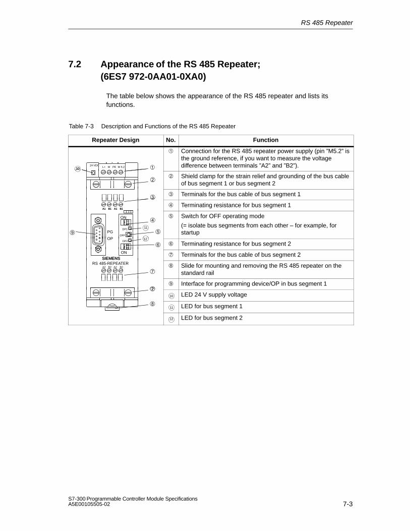
RS 485 Repeater
7-3S7-300 Programmable Controller Module SpecificationsA5E00105505-02
7.2 Appearance of the RS 485 Repeater;(6ES7 972-0AA01-0XA0)
The table below shows the appearance of the RS 485 repeater and lists itsfunctions.
Table 7-3 Description and Functions of the RS 485 Repeater
Repeater Design No. Function
24 VDCL+ M PE M 5.2 10
Connection for the RS 485 repeater power supply (pin ”M5.2” isthe ground reference, if you want to measure the voltagedifference between terminals ”A2” and ”B2”).
10
Shield clamp for the strain relief and grounding of the bus cableof bus segment 1 or bus segment 2
Terminals for the bus cable of bus segment 1
A1 B1 A1 B1 Terminating resistance for bus segment 1
A1 B1 A1 B1
PG11
OFF
ON
DP1
Switch for OFF operating mode
(= isolate bus segments from each other – for example, forstartup
OPDP2
12
Terminating resistance for bus segment 2
SIEMENS
ON Terminals for the bus cable of bus segment 2
SIEMENSRS 485-REPEATER
A2 B2 A2 B2 Slide for mounting and removing the RS 485 repeater on the
standard rail
Interface for programming device/OP in bus segment 1
10 LED 24 V supply voltage
11 LED for bus segment 1
12 LED for bus segment 2

RS 485 Repeater
7-4S7-300 Programmable Controller Module Specifications
A5E00105505-02
7.3 RS 485 Repeater in Ungrounded and GroundedOperation
Grounded or ungrounded
The RS 485 repeater is ...
Grounded, if all other nodes in the segment are also operated with a groundedpotential
Ungrounded, if all other nodes in the segment are operated with an ungroundedpotential
Note
The bus segment 1 is grounded if you connect a programming device to thePG/OP socket of the RS 485 repeater. Ground connection is effected since theMPI in the programming device is grounded and the PG/OP socket is connectedinternally with bus segment 1 in the RS 485 repeater.
Grounded operation of the RS 485 repeater
For grounded operation of the RS 485 repeater, you must jump terminals ”M” and”PE” on the top of the RS 485 repeater.
Ungrounded operation of the RS 485 repeater
For ungrounded operation of the RS 485 repeater, ”M” and ”PE” on the top of theRS 485 repeater must not be interconnected. In addition, the supply voltage of theRS 485 repeater must be ungrounded.

RS 485 Repeater
7-5S7-300 Programmable Controller Module SpecificationsA5E00105505-02
Terminal connection diagram
In the case of a repeater configuration with ungrounded reference potential(ungrounded operation), any interference currents and static charges aredischarged by means of an RC network integrated in the repeater (refer toFigure 7-1) to the protective conductor.
24 VDCL+ M PE M 5.2
A1 B1 A1 B1
M
22 nF 10 MΩ
Ground bus
PE
Figure 7-1 RC Network with 10 MΩ for Configuration with Ungrounded ReferencePotential
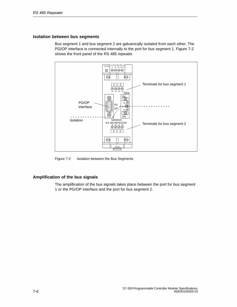
RS 485 Repeater
7-6S7-300 Programmable Controller Module Specifications
A5E00105505-02
Isolation between bus segments
Bus segment 1 and bus segment 2 are galvanically isolated from each other. ThePG/OP interface is connected internally to the port for bus segment 1. Figure 7-2shows the front panel of the RS 485 repeater.
24 VDCL+ M PE M 5.2
SIEMENSRS 485-REPEATER
ON
A1 B1 A1 B1
A2 B2 A2 B2
PG
OPDP2
OFF
ON
DP1
Terminals for bus segment 1
Terminals for bus segment 2
PG/OPinterface
Isolation
Figure 7-2 Isolation between the Bus Segments
Amplification of the bus signals
The amplification of the bus signals takes place between the port for bus segment1 or the PG/OP interface and the port for bus segment 2.
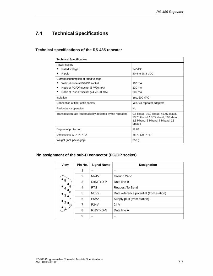
RS 485 Repeater
7-7S7-300 Programmable Controller Module SpecificationsA5E00105505-02
7.4 Technical Specifications
Technical specifications of the RS 485 repeater
Technical Specification
Power supply
Rated voltage 24 VDC
Ripple 20.4 to 28.8 VDC
Current consumption at rated voltage
Without node at PG/OP socket 100 mA
Node at PG/OP socket (5 V/90 mA) 130 mA
Node at PG/OP socket (24 V/100 mA) 200 mA
Isolation Yes, 500 VAC
Connection of fiber optic cables Yes, via repeater adapters
Redundancy operation No
Transmission rate (automatically detected by the repeater) 9.6 kbaud, 19.2 kbaud, 45.45 kbaud,93.75 kbaud, 187.5 kbaud, 500 kbaud.1.5 Mbaud. 3 Mbaud, 6 Mbaud, 12Mbaud
Degree of protection IP 20
Dimensions W H D 45 128 67
Weight (incl. packaging) 350 g
Pin assignment of the sub-D connector (PG/OP socket)
View Pin No. Signal Name Designation
1 – –
2 M24V Ground 24 V5 3 RxD/TxD-P Data line B
94 4 RTS Request To Send4
8 5 M5V2 Data reference potential (from station)3
7 6 P5V2 Supply plus (from station)2
6 7 P24V 24 V1 8 RxD/TxD-N Data line A
9 – –

RS 485 Repeater
7-8S7-300 Programmable Controller Module Specifications
A5E00105505-02
Block diagram of the RS 485 repeater
Bus segment 1 and bus segment 2 are galvanically isolated from each other.
Bus segment 2 and the PG/OP socket are galvanically isolated from eachother.
Signals are amplified
– between bus segment 1 and bus segment 2
– between PG/OP socket and bus segment 2
5V
24V
Segment 2A2B2A2B2
Segment 1A1B1A1B1
PG/OP-socket
L+ (24 V)M
A1B15 V
M5 V
L+ (24 V)M
PEM 5.2
Logic
5V
24V
1M1M
Figure 7-3 Block Diagram of the RS 485 Repeater

8-1S7-300 Programmable Controller Module SpecificationsA5E00105505-02
SIMATIC TOP connect and SIMATIC TOPconnect TPA
Changes and improvements compared with the last edition of the Reference Manual
The descriptions of SIMATIC TOP connect and SIMATIC TOP connect TPA aresummarized in this chapter. In this way it was possible to extract and giveprecedence to generally valid information.
A new overview section will make it easier for you to access the information.
The section entitled ”Module Overview” shows the basic configuration of SIMATICTOP connect and SIMATIC TOP connect TPA. In addition, you will also find outwhich modules in the S7-300 family can be used with SIMATIC TOP connect/...TPA.
In this chapter
Section Contents Page
8.1 Module Overview 8-2
8.2 Wiring Components 8-4
8.3 Wiring SIMATIC TOP connect with Digital Modules 8-12
8.4 Wiring SIMATIC TOP connect TPA with Analog Modules 8-20
Structure of the chapter
Sections 8.1 and 8.2 apply to SIMATIC TOP connect and SIMATIC TOP connectTPA.
Section 8.3 contains specific information on SIMATIC TOP connect and thussupplements the preceding sections.
Section 8.4 contains specific information on SIMATIC TOP connect TPA and thussupplements Sections 8.1 und 8.2.
8

SIMATIC TOP connect and SIMATIC TOP connect TPA
8-2S7-300 Programmable Controller Module Specifications
A5E00105505-02
8.1 Module Overview
Introduction
”SIMATIC TOP connect” denotes components for wiring digital modules.
”SIMATIC TOP connect TPA” denotes components for wiring analog modules.
Wiring
Wiring with SIMATIC TOP connect/... TPA is a fast and cost-effective alternative toconventional wiring of the actuators and sensors directly at the front connector ofthe module. When using these components, you wire actuators and sensors ”insitu” on one more terminal blocks. You establish the connection to the module bymeans of a connecting cable (round-sheath ribbon cable).
Configuration of SIMATIC TOP connect with a S7-300
A SIMATIC TOP connect and a SIMATIC TOP connect TPA always consist of:
A front connector module with flat ribbon connection ,
One or more terminal blocks and
One or more connecting cables with plug-and-socket connectors at ends
Figure 8-1 SIMATIC TOP connect on a S7-300

SIMATIC TOP connect and SIMATIC TOP connect TPA
8-3S7-300 Programmable Controller Module SpecificationsA5E00105505-02
Advantages
Use of SIMATIC TOP connect/... TPA features the following advantages:
Fast, low-cost wiring (the use of central terminal blocks is no longer necessary)
Simple mounting of the components (front connector module, connecting cable,terminal block)
Each component can be replaced separately
Connecting cable configurable without waste
Wiring errors are drastically reduced
Neat and tidy cabinet wiring
The supply voltage for the module can be connected to components ofSIMATIC TOP connect/... TPA
Simplification of the terminals for M- and L+ connection
Range of modules
The table below lists all the modules which you can wire with SIMATIC TOPconnect and SIMATIC TOP connect TPA.
You will find a detailed list of the components of SIMATIC TOP connect/... TPAwith their order numbers in Table 8-5 on page 8-12 and Table 8-13 on page 8-20.
Table 8-1 SIMATIC TOP connect/... TPA: Connectable Modules
Component Front view of terminal block Wiring possible with module...
SIMATIC TOPconnect
SM 321; DI 32DC 24 V
SM 321; DI 16DC 24 V
SM 321; DI 1624 VDC; source input
SM 322; DO 32DC 24 V/0.5 A
SM 322; DO 16DC 24 V/0.5 A
SM 322; DO 824 VDC/0.5 A with diagnosticinterrupt
SM 322; DO 8DC 24 V/2 A
SM 323; DI 16/DO 16DC 24 V/0.5 A
SM 323; DI 8/DO 8DC 24 V/0.5 A
SIMATIC TOPconnect TPA
SM 331 analog input module; AI 212 bits
SM 331; AI 812bits
connect TPA
A B C D E F G H I K
SM 332; AO 412bits
SM 332 analog output module; AO 212 bits
SM 332; AO 416bits
Y Y K K A A A A Z ZY Z
SM 334; AI 4/AO 28/8bits
SM 334; AI 4/AO 212bits
SM 335; AI 4/AO 414 bits;

SIMATIC TOP connect and SIMATIC TOP connect TPA
8-4S7-300 Programmable Controller Module Specifications
A5E00105505-02
8.2 Wiring Components
Introduction
The following table contains the tasks that you have to perform one after the otherto commission SIMATIC TOP connect/... TPA successfully.
The sequence of steps is a suggestion but you can perform individual steps sooneror later.
Sequence of steps for wiring
Table 8-2 Sequence of Steps for Wiring SIMATIC TOP connect/... TPA
Step Procedure Refer to Section...
1. Cut connecting cable to length and terminate 8.2.1
2. Wire the front connector module 8.2.2 and 8.3 or 8.4
3. Connect the connecting cable to the terminalblock
8.2.3 and 8.3 or 8.4
4. Wire actuators/sensors to the terminal block 8.2.4
8.2.1 Cut the Connecting Cable to Length and Terminate
Maximum length of cable
The length of the connecting cable (round-sheath ribbon cable) between theSIMATIC S7 and the terminal blocks must not be more than 30 m.
Using the connectors
You must attach connectors to either end of the round-sheath ribbon cable, forconnection to the front connector module and the terminal block.
Connect the round-sheath ribbon cable to connector
1. Cut the round-sheath ribbon cable to the length required and remove part of thecable sheath at both ends.
You will find the length of the cable sheath that has to be removed in thefollowing table:

SIMATIC TOP connect and SIMATIC TOP connect TPA
8-5S7-300 Programmable Controller Module SpecificationsA5E00105505-02
Cable sheath tobe removed
externalribboncable
internalribboncable
externalribboncable
internalribboncable
Cable end to ... 20-pinfront
connec-tor
40-pinfront
connec-tor
20-pin front connector
40-pin front connector
... top connector of frontconnector module 1 x 16 core 110 mm 115 mm
... bottom connector offront connector module
shielded/unshielded
70 mm 75 mm
... top connector of frontconnector module 95 mm 115 mm
... bottom connector offront connector module
2 x 16 coreunshielded
95 mm 115 mm
40 mm 75 mm
... socket of terminalblock
40 mm 100 mm
2. Thread the cable into the 16-pin connector.
It is important that you note the position of the details marked in the followingfigure.
Triangle
Nose
Marked Core
Figure 8-2 Threading the Round-Sheath Ribbon Cable into the Connector
3. Clamp the end of the cable into the connector with the crimping tool.
4. Attach the strain relief device to the connector of the terminal block as follows:
– Fold back the cable over the connector
– Push the enclosed strain relief device over the cable
– Snap the strain relief device into place on the connector

SIMATIC TOP connect and SIMATIC TOP connect TPA
8-6S7-300 Programmable Controller Module Specifications
A5E00105505-02
8.2.2 Wiring the Front Connector Module
Introduction
This chapter describes the principle of wiring the front connector modules. Notealso the special sections for SIMATIC TOP connect and SIMATIC TOP connectTPA (Section 8.3 and 8.4, respectively). In those sections, you will find, amongother things, selection criteria for the front connector modules and specificconnection examples.
Using the front connector module
You require the front connector module to connect the connecting cable to themodule. In addition, you can connect the supply voltage of the module to the frontconnector module.

SIMATIC TOP connect and SIMATIC TOP connect TPA
8-7S7-300 Programmable Controller Module SpecificationsA5E00105505-02
Wiring rules for connecting the supply voltage
The following table shows you what you have to consider when connecting themodule supply voltage to the terminal block or front connector module.
The terminals for the supply voltage are screws or spring-loaded terminals (refer toSection 8.2.4 for handling spring-loaded terminals).
Table 8-3 Wiring Rules for Connecting the Supply Voltage
Rules for ... Terminal block Front connector
Spring-loadedconnection
Screw-typeconnection
Up to 4Terminals
Up to 8Terminals
Conductorcross-sections suitablefor connection:
Solid conductors No No No
Stranded conductors
Without end ferrules
With end ferrules
0.25 to1.5 mm2
0.25 to 1.5 mm2
0.25 to1.5 mm2
0.25 to1.5 mm2
0.25 to0.75 mm2
0.25 to0.75 mm2
No of conductors perterminal
1 or combination of 2 conductors up to 1.5 mm2 (sum) in a common end ferrule
Max. diameter ofconductor insulation
∅ 3.1 mm ∅ 3.1 mm ∅ 2.0 mm
Length of conductorinsulation to be stripped
Without insulationcollar
With insulation collar
11 mm
11 mm
6 mm
–
End ferrules toDIN 46228
Without insulationcollar
With insulation collar
– 0.25 to 1.0 mm2
– 1.5 mm2
Model A; up to 12 mmlong
Model E; up to 12 mmlong
Model E; 12 mm long
Model A; up to 12 mmlong
Model E; up to 12 mmlong
Model E; 18 mm long
Model A; 5 to 7 mm long
–

SIMATIC TOP connect and SIMATIC TOP connect TPA
8-8S7-300 Programmable Controller Module Specifications
A5E00105505-02
Connect the connecting cable and the supply voltage to the front connectormodule
1. Open the front door of the module.
2. Bring the front connector into the wiring position.
3. If necessary, connect the cables for the incoming supply of the module supplyvoltage.
4. Insert the connecting cable into the front connector module as shown in thefollowing figure:
Figure 8-3 Inserting the Connecting Cable into the Front Connector Module
5. Twist every connecting cable 90 downwards and turn through one whole turnto the extent possible.
Additional steps for wiring for 32-channel digital modules
Note
When using 32-channel digital modules, you must observe the assignment of thesupply connections to the connecting cable terminals and the assignment of theconnecting cable terminals to the address bytes of the module (refer to Figure 8-4and Table 8-4).
6. Thread a strain relief assembly into the middle of the front connector. Thisstrain relief assembly is used to fix the connecting cables in the narrow cablestowage area of the module.
7. Thread the strain relief assembly into the front connector.

SIMATIC TOP connect and SIMATIC TOP connect TPA
8-9S7-300 Programmable Controller Module SpecificationsA5E00105505-02
Front connector module for 32-channel digital modules
The following figure shows the front view of the front connector module for32-channel digital modules.
+_
+_
+_
+_
Supply terminals for
Supply terminals for
Supply terminals for
Supply terminals for
Openings for strain relief
to : Terminals for connecting cable; refer to Table 8-4 for the address assignment
Opening for thescrewdriver
Opening for the cable to be connected
Legend:
Figure 8-4 Front connector module for 32-channel digital modules
Assignment of connecting cable terminals to address bytes of 32-channel digitalmodules
Table 8-4 Assignment of Connecting Cable Terminals to Address Bytes of 32-ChannelDigital Modules
Refer to Address Assignment forFigure 8-4:Connecting
Cable TerminalDigital Input
ModuleDigital Output
ModuleDigital Input/Output
Module
IB x QB x IB x
IB (x+1) QB (x+1) IB (x+1)
IB (x+2) QB (x+2) QB x
IB (x+3) QB (x+3) QB (x+1)

SIMATIC TOP connect and SIMATIC TOP connect TPA
8-10S7-300 Programmable Controller Module Specifications
A5E00105505-02
8.2.3 Connecting the Connecting Cable to the Terminal Block
Introduction
A description of how to mount the terminal blocks is presented in the following.Note also the special sections for SIMATIC TOP connect and SIMATIC TOPconnect TPA (Section 8.3 and 8.4, respectively). In those sections, you will find,among other things, selection criteria for the different terminal blocks and specificconnection examples.
Mounting the terminal block and connecting cable
1. Attach the terminal block to a 35 mm standard rail in accordance with EN 50 022.
2. Insert the connecting cable into the terminal block as shown in the followingfigure:
Figure 8-5 Insert the Connecting Cable into the Terminal Block
8.2.4 Wiring Actuators/Sensors to the Terminal Block
Screw-type or spring-loaded terminals
To mount the signal leads of the actuators/sensors to the terminal block and thesupply lines to the terminal block and front connector module, you can choosebetween screw-type and spring-loaded components.
The principle of spring-loaded components is dealt with in greater detail in thefollowing, since it allows fast and simple connection of the signal lines and supplycables.

SIMATIC TOP connect and SIMATIC TOP connect TPA
8-11S7-300 Programmable Controller Module SpecificationsA5E00105505-02
Spring-loaded terminal block
Opening for thescrewdriver for pressingthe spring-loaded contact
Opening for the cable tobe connected
Figure 8-6 Spring-Loaded Terminal Block
!Caution
The spring-loaded contact will be damaged, if you insert the screwdriver into theopening for the cable.
Make sure that you insert the screwdriver only into the rectangular opening of theterminal block.
Attaching the cable to the spring-loaded contact
Attach the cables to the spring-loaded contacts as follows:
1. Use a screwdriver to press down the spring-loaded terminal in therectangular opening and to hold it down.
2. Insert the cable into the round opening of the corresponding spring-loadedterminal as far as it will go.
3. Remove the screwdriver from the spring-loaded terminal. The cable is heldby the spring-loaded contact.
Figure 8-7 Principle of Spring-Loaded Connections

SIMATIC TOP connect and SIMATIC TOP connect TPA
8-12S7-300 Programmable Controller Module Specifications
A5E00105505-02
8.3 Wiring SIMATIC TOP connect with Digital Modules
Introduction
For wiring the module with actuators/sensors using SIMATIC TOP connect, youmust first select the components as a function of the module and method ofconnection (screw type or spring-loaded terminal, one-conductor, three-conductoror 2A connection; relay).
8.3.1 SIMATIC TOP connect Components and Selection Aid
Components
The following table contains all the component of SIMATIC TOP connect.
Table 8-5 Components of SIMATIC TOP connect
Components of SIMATIC TOP connect Order number
Terminalblock
... for one-conductorconnection
Spring-loaded screw-type 6ES7 924-0AA00-0AB06ES7 924-0AA00-0AA0
... for one-conductorconnection (10 items)
Spring-loaded screw-type 6ES7 924-0AA00-1AB06ES7 924-0AA00-1AA0
... for three-conductorconnection
Spring-loaded screw-type 6ES7 924-0CA00-0AB06ES7 924-0CA00-0AA0
... for three-conductorconnection (10 items)
Spring-loaded screw-type 6ES7 924-0CA00-1AB06ES7 924-0CA00-1AA0
... for 2A modules Spring-loaded screw-type
6ES7 924-0BB00-0AB06ES7 924-0BB00-0AA0
... for 2A modules (10 items) Spring-loaded screw-type 6ES7 924-0BB00-1AB06ES7 924-0BB00-1AA0
... for relays Spring-loaded screw-type 6ES7 924-0CD00-0AB06ES7 924-0CD00-0AA0
Frontconnector
for 32-channel modules(refer to Figure 8-4)
Voltage supply via:Spring-loaded terminals 6ES7 921 3AA20-0AA0
for 16-channel modules Voltage supply via:spring-loaded screw-type 6ES7 921-3AA00-0AA0
6ES7 921-3AB00-0AA0
for 16-channel 2A modules Voltage supply via:spring-loaded screw-type 6ES7 921-3AC00-0AA0
6ES7 921-3AD00-0AA0
Connectors (plug-in connectors), set of 8 (insulation displacementconnectors)
6ES7 921-3BE10-0AA0

SIMATIC TOP connect and SIMATIC TOP connect TPA
8-13S7-300 Programmable Controller Module SpecificationsA5E00105505-02
Table 8-5 Components of SIMATIC TOP connect, continued
Components of SIMATIC TOP connect Order number
Round-sheathribbon cable
Unshielded 30 m60 m
6ES7 923-0CD00-0AA06ES7 923-0CG00-0AA0
1x 16Shielded 30 m
60 m6ES7 923-0CD00-0BA06ES7 923-0CG00-0BA0
Round-sheathribbon cable 2 x 16
Unshielded 30 m60 m
6ES7 923-2CD00-0AA06ES7 923-2CG00-0AA0
Crimping tool for 16-pin connector 6ES7 928-0AA00-0AA0
Selection aid
In the following table you will find the components of SIMATIC TOP connect withwhich you can wire the digital modules.
Table 8-6 Selection Table for SIMATIC TOP connect Components
Digital Modules Terminal block for... Front connectormodule for...
One-con-ductor
connection
Three-con-ductor
connection
2Amod-ules
Relays SM; 16 or 32
channels
2Amod-ules
SM 321; DI 32 24 VDC – – –
SM 321; DI 16 24 VDC – – –
SM 321; DI 16 24 VDC; source input
– – –
SM 322; DO 32 24 VDC/0.5 V – –
SM 322; DO 16 24 VDC/0.5 V – –
SM 322; DO 8 24VDC/0.5 V;with diagnostic interrupt
– – –
SM 322; DO 8 24 VDC/2 A – – – –
SM 323; DI 16/DO 1624VDC/0.5 A
– – –
SM 323;DI 8/DO 824 VDC/0.5 A
– – –
One-conductor or three-conductor connection
With the three-conductor connection, you can optionally apply the supply voltagefor the module to the front connector module or to the terminal block. With theone-conductor connection, this can only be done to the front connector module.

SIMATIC TOP connect and SIMATIC TOP connect TPA
8-14S7-300 Programmable Controller Module Specifications
A5E00105505-02
2A module connection
You require the following information on wiring 2A modules only when you want touse the SM 322; 8DO 24 VDC/2 A with SIMATIC TOP connect.
8.3.2 Wiring the Module with Terminal Block for One-ConductorConnection
Connection Notes
Table 8-7 Connection Notes for SIMATIC TOP connect with One-Conductor Connection
Digital Modules Connection Notes
Supply Voltage Feed-In Additional Descrip-
At frontconnector
only
Add.groundconn. atterminal
block
At frontconnectoror terminal
block
jumper re-quired at
power sup-ply
tion on ter-minal
block notin line withdescription
on SM
SM 321; DI 3224 VDC – – – –
SM 321; DI 1624 VDC – – – –
SM 321; DI 1624 VDC; sourceinput
– – – –
SM 322; DO 3224 VDC/0.5 A – – – –
SM 322; DO 1624 VDC/0.5 A – – – –
SM 322; DO 824 VDC/0.5 Awith diagnostic interrupt
– – –
SM 323; DI 16/DO 16DC 24 V/0.5 A
– – – –
SM 323; DI 8/DO 824 VDC/0.5 A
– – – –

SIMATIC TOP connect and SIMATIC TOP connect TPA
8-15S7-300 Programmable Controller Module SpecificationsA5E00105505-02
Assignments of the terminal block for one-conductor connection
Table 8-8 Terminal Assignments of the Terminal Block for One-Conductor Connection
Front view of terminal block Assignments of the Terminals
Top row:Terminals 0 to 7: inputs/outputs x.0 to x.7
Connecting the power supply
Always connect the supply voltage to the front connector module Observe thewiring rules in Table 8-3 on page 8-7.
In the following example, you must connect L+ to Plus of the upper terminal and Mto Minus of the lower terminal.
Connecting the terminal block for one-conductor connection
12
34
56
78
910
Front connector module
–+
1112
1314
1516
1718
1920
L+
M
–+
Terminal block Terminal block
Figure 8-8 Wiring a Digital Module with Terminal Block for a One-Conductor Connection

SIMATIC TOP connect and SIMATIC TOP connect TPA
8-16S7-300 Programmable Controller Module Specifications
A5E00105505-02
8.3.3 Wiring the Module with Terminal Block for Three-ConductorConnection
Connection Notes
Table 8-9 Connection Notes for SIMATIC TOP connect with Three-Conductor Connection
Digital modules Connection notes
Supply voltage feed-in Additional Descrip-
At frontconnector
only
Add.groundconn. atterminal
block
At frontconnectoror terminal
block
jumper re-quired at
power sup-ply
tion on ter-minal
block notin line withdescription
on SM
SM 321; DI 3224 VDC – – –
SM 321; DI 1624 VDC – – –
SM 321; DI 1624 VDC; sourceinput
– – –
SM 322; DO 3224 VDC/0.5 A – – – –
SM 322; DO 1624 VDC/0.5 A – – – –
SM 322; DO 824 VDC/0.5 Awith diagnostic interrupt
– –
SM 323; DI 16/DO 1624VDC/0.5 A
– – – –
SM 323; DI 8/DO 824 VDC/0.5 A
– – – –
Assignment of the terminal block for three-conductor connection
Table 8-10 Terminal Assignments of the Terminal Block for Three-Conductor Connection
Front view of terminal block Assignments of the Terminals
Top row:Terminals 0to 7:inputs/outputs x.0 to x.7
Center row:All terminals: M potential
Bottom row:All terminals: L + potential

SIMATIC TOP connect and SIMATIC TOP connect TPA
8-17S7-300 Programmable Controller Module SpecificationsA5E00105505-02
Connecting the power supply
Observe the wiring rules in Table 8-3 on page 8-7.
With some digital modules, two jumpers are generally required for connecting thesupply voltage (refer to Table 8-9 on page 8-16).
You can wire the jumpers either in the front connector or in the terminal block.Irrespective of this, you must interconnect the two Plus terminals and the twoMinus terminals.
Connecting the terminal block for three-conductor connection
12
34
56
78
910
Front connector
Terminal block
–+
1112
1314
1516
1718
1920
L+
M
– +
Terminal block
Jumper (2)
Jumper (1)
Jumper (1) or jumper (2) required
Figure 8-9 Wiring a Digital Module with Terminal Block for a Three-Conductor Connection

SIMATIC TOP connect and SIMATIC TOP connect TPA
8-18S7-300 Programmable Controller Module Specifications
A5E00105505-02
8.3.4 Wiring the Module with Terminal Block for 2A Modules
You can use the terminal block for 2A modules to wire the SM 322;8DO 24 VDC/2A.
Connection Notes
Table 8-11 Connection Notes for SIMATIC TOP connect with 2A Module Connection
Digital Modules Connection Notes
Supply Voltage Feed-In Add. Descr. on
At frontconnector
only
Add.groundconn. atterminal
block
At frontconnectoror terminal
block
jumper re-quired for
power sup-ply
terminalblock not
in line withdescr. on
SM
SM 322; DO 1624 VDC/2 A – – –
Assignment of the terminal block for connection of 2A modules
Table 8-12 Terminal Assignments of the Terminal Block for 2A Modules
Front View of Terminal Block Assignments of theTerminals (left)
Assignments of theTerminals (right)
Top row:Terminals 0 to 3: outputs x.0 to x.3
Top row, on right:Terminals 0 to 3: outputs x.4 to x.7
Center row:Terminals 0 to 3:potential M1 for x.0 tox.3
Center row, on right:Terminals 0 to 3:potential M2 for x.4 tox.7
M1 M2Bottom row:two-terminalconnection for M1
Bottom row:two-terminalconnection for M2

SIMATIC TOP connect and SIMATIC TOP connect TPA
8-19S7-300 Programmable Controller Module SpecificationsA5E00105505-02
Connecting the power supply
Please observe the following when connecting the power supply:
Apply the wiring rules in Table 8-3 on page 8-7.
Connect the supply voltage at the front connector module to the potentialterminals using separate cables.
You must equip each terminal block with a cable for M1 or M2, in addition to theconnecting cable.
Connect M1 or M2 via a separate line with the front connector and the terminalblock. You may jumper the potential of M1 and M2.
Connection to terminal block for 2A modules
Front connector
–+
1112
1314
151617
1819
20
1 L+
2 M
– +
123
45
67
89
101 M2 L+
Terminalblock
M 1
M 2
Figure 8-10 Wiring with Terminal Block for 2A Module

SIMATIC TOP connect and SIMATIC TOP connect TPA
8-20S7-300 Programmable Controller Module Specifications
A5E00105505-02
8.4 Wiring SIMATIC TOP connect TPA with Analog Modules
Introduction
For wiring the module with actuators/sensors using SIMATIC TOP connect TPA,you must first select the components as a function of the method of connection(screw-type or spring-loaded terminal).
8.4.1 SIMATIC TOP connect TPA Components and Selection Aid
Components
The following table contains all the component of SIMATIC TOP connect TPA.
Table 8-13 Components for SIMATIC TOP connect TPA
Components of SIMATIC TOP connect TPA Order number
Terminal block Quantity: 1 Spring-loaded terminals
Screw-type terminals
6ES7 924-0CC00-0AB0
6ES7 924-0CC00-0AA0
Quantity: 10 Spring-loaded terminals
Screw-type terminals
6ES7 924-0CC00-1AB0
6ES7 924-0CC00-1AA0
Front connector Voltage supply via:
Spring-loaded terminals
Screw-type terminals 6ES7 921-3AF00-0AA0
6ES7 921-3AG00-0AA0
Connectors (plug-in connectors), set of 8 (insulationdisplacement connectors)
6ES7 921-3BE10-0AA0
Shielding plate for terminal block, set of 4 6ES7 928-1BA00-0AA0
Terminal element for:
2 cables, each with a shield diameter of 2 to 6 mm
1 cable with a shield diameter of 3 to 8 mm
1 cable with a shield diameter of 4 to 13 mm
6ES7 390-5AB00-0AA0
6ES7 390-5BA00-0AA0
6ES7 390-5CA00-0AA0
Round-sheath ribbon cable, shielded∅ 8 mm
30 m
60 m
6ES7 923-0CD00-0BA0
6ES7 923-0CG00-0BA0
Crimping tool for 16-pin connector 6ES7 928-0AA00-0AA0

SIMATIC TOP connect and SIMATIC TOP connect TPA
8-21S7-300 Programmable Controller Module SpecificationsA5E00105505-02
8.4.2 SIMATIC TOP connect TPA Terminal Assignment and TerminalAllocation
Terminal marking
On the TPA terminal block, the terminals are identified by letters. This simplifiesthe allocation of the terminals on the analog module to the terminals on theterminal block.
Terminal block assignment
Table 8-14 Terminal Assignment of the Terminal Block of SIMATIC TOP connect TPA
Front view of terminal block Assignments of the Terminals
Terminals Z and Y can be used for multiplying arbitrarypotentials and signals.
A B C D E F G H I K
Y Y K K A A A A Z ZY Z
The terminals having identical letters are electricallyinterconnected, with the exception of terminals Z andZ, and also Y and Y.
Multiplier terminal
The lower tier of terminals on the terminal block is designed as 2 5 multiplierterminals.

SIMATIC TOP connect and SIMATIC TOP connect TPA
8-22S7-300 Programmable Controller Module Specifications
A5E00105505-02
Terminal allocation of an analog module to SIMATIC TOP connect TPA
Terminalnumber onmodule
Terminal assignment onterminal block TPA
Terminal block 1 Terminal block 2
12
11
13141516171819
20
Y
BCDEFGHI
K
A
Z
Y
K
B
A
CDEFGHI
Z
12
11
13141516171819
20
2
1
3456789
10
2
1
3456789
10
Figure 8-11 Terminal Assignment of Analog Module to SIMATIC TOP connect TPA

SIMATIC TOP connect and SIMATIC TOP connect TPA
8-23S7-300 Programmable Controller Module SpecificationsA5E00105505-02
8.4.3 Connecting the Signal-Line Shield
Two options for connecting the shield
You can connect the signal line shield to ground as follows:
On the analog module by means of a shield-support element
(refer to the manual Hardware and Installation for the S7-300 or the manualDistributed I/O device ET 200M in the section on wiring)
Directly to the terminal block by means of a shielding plate
Connecting the shield to the terminal block using a shielding plate
1. Before mounting, attach a shielding plate to the terminal block.
2. Mount the terminal block on the DIN rail.
(In the figure below, you can see that the shielding plate is applied to the rear ofthe terminal block and thus there is a connection to the grounded rail.)
3. Place the signal-line shield with the shield terminals on the shielding plate.
Shield support for shield terminal andconnecting cable to analog module
Terminal block
Shield support fro shield terminaland signal lines fromactuators/sensors
Shieldingplate
Snap the shielding plate into place at the rear of the terminal block.
Loosenshielding plate
Snap theshielding plateinto place
Press down lightly on therelease to loosen theshielding plate
Figure 8-12 SIMATIC TOP connect TPA Terminal Block with Shielding Plate

SIMATIC TOP connect and SIMATIC TOP connect TPA
8-24S7-300 Programmable Controller Module Specifications
A5E00105505-02
8.4.4 Connection Example
Connecting the load voltage supply
You can connect the load voltage supply of the analog module to the frontconnector module. Their are separate terminals on the front connector module forthe load voltage L+ und M. Observe the wiring rules in Table 8-3 on page 8-7.
Allocation of front connector to terminal block
The upper socket of the front connector module is the connection for terminalblock 1 and the lower socket of the front connector module is the connection forterminal block 2.
Connection example
The illustration below shows an example of connecting the analog input moduleSM 321; AI 812 bits in ”Resistance Test” mode.
Comp–/ Mana
Resistance test
Comp +
SF
M
L+
M0 + CH0M0IC0 +IC0
M1 + CH2M1
IC1 +
IC1
M2 + CH4M2IC2 +IC2
M3 + CH6M3
IC3 +IC3
Comp
M
L +
M
Terminal assignment onterminal block TPA
Terminalblock 1
Terminalblock 2
1211
131415
1617181920
Y
BCDE
FGHI
K
A
Z
Y
K
BA
CDE
FGHIZ
2
1
345
6789
10
Terminal number onmodule
Figure 8-13 Example of Connecting SIMATIC TOP connect TPA to SM 321; AI 812 bits

A-1S7-300 Programmable Controller Module SpecificationsA5E00105505-02
Parameter Sets for Signal Modules
In this chapter
Section Contents Page
A.1 How to Assign the Parameters for Signal Modules in the UserProgram
A-1
A.2 Parameters of the Digital Input Modules A-3
A.3 Parameters of the Digital Output Modules A-5
A.4 Parameters of the Analog Input Modules A-7
A.5 Parameters of the SM 331; AI 8 RTD A-11
A.6 Parameters der SM 331; AI 8TC A-19
A.7 Parameters of the SM 331; AI 813 bits A-27
A.8 Parameters of the SM 331; AI 816 bits A-29
A.9 Parameters of the Analog Output Modules A-35
A.10 Parameters of the SM 332; AO 812 bits A-38
A.11 Parameters of the Analog Input/Output Modules A-40
A.1 How to Assign the Parameters for Signal Modules in the UserProgram
Parameter assignment in the user program
You have already assigned parameters to the modules in STEP 7.
In the user program, you can use a SFC:
To reassign parameters to the module and
To transfer the parameters from the CPU to the addressed signal module
A

Parameter Sets for Signal Modules
A-2S7-300 Programmable Controller Module Specifications
A5E00105505-02
Parameters stored in data records
The parameters of the signal modules are located in data records 0 and 1; forsome other analog input modules, in data record 128 as well.
Modifiable parameters
You can change the parameters of record 1 and pass them to the signal moduleusing SFC 55. The parameters set on the CPU are not changed when you do this!
You cannot modify the parameters of data record 0 in the user program.
SFCs for parameter assignment
The following SFCs are available for assigning parameters to the signal modules inthe user program:
Table A-1 SFCs for Assigning Parameters to Signal Modules
SFCNo.
Identifier Application
55 WR_PARM Transfer modifiable parameters (data record 1 and 28)to the addressed signal module.
56 WR_DPARM Transfer parameters (data record 0, 1 or 128) from theCPU to the addressed signal module.
57 PARM_MOD Transfer all parameters (data record 0, 1 and 128)from the CPU to the addressed signal module.
Description of the parameters
The following sections contain all the modifiable parameters for the various moduleclasses. The parameters of the signal modules are described:
In the on-line help of STEP 7
In this reference manual
You will find the parameters that can be adjusted for the signal moduleconcerned in the specific sections for the different signal modules.
Further references
An in-depth description of the principle of assigning parameters to signal modulesin the user program and a description of the SFCs that can be used for thatpurpose will be found in the STEP 7 manuals.
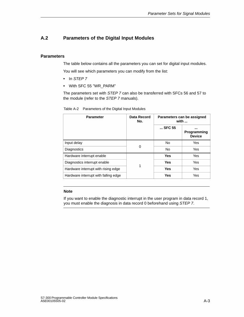
Parameter Sets for Signal Modules
A-3S7-300 Programmable Controller Module SpecificationsA5E00105505-02
A.2 Parameters of the Digital Input Modules
Parameters
The table below contains all the parameters you can set for digital input modules.
You will see which parameters you can modify from the list:
In STEP 7
With SFC 55 ”WR_PARM”
The parameters set with STEP 7 can also be transferred with SFCs 56 and 57 tothe module (refer to the STEP 7 manuals).
Table A-2 Parameters of the Digital Input Modules
Parameter Data RecordNo.
Parameters can be assignedwith ...
... SFC 55 ...Programming
Device
Input delay No Yes
Diagnostics0
No Yes
Hardware interrupt enable Yes Yes
Diagnostics interrupt enable Yes Yes
Hardware interrupt with rising edge1
Yes Yes
Hardware interrupt with falling edge Yes Yes
Note
If you want to enable the diagnostic interrupt in the user program in data record 1,you must enable the diagnosis in data record 0 beforehand using STEP 7.

Parameter Sets for Signal Modules
A-4S7-300 Programmable Controller Module Specifications
A5E00105505-02
Data record 1 structure
The figure below shows the structure of data record 1 for the parameters of thedigital input modules.
You activate a parameter by setting the corresponding bit to ”1”.
Byte 07 6 0
Hardware interrupt enableDiagnostics interrupt enable
Byte 17 6 0
on rising edge at channel group 0on falling edge at channel group 0
on rising edge at channel group 1
on falling edge at channel group 1on rising edge at channel group 2
on falling edge at channel group 2on rising edge at channel group 3
on falling edge at channel group 3
5 4 3 2 1
Byte 27 6 0
on rising edge at channel group 4on falling edge at channel group 4
on rising edge at channel group 5 on falling edge at channel group 5
on rising edge at channel group 6on falling edge at channel group 6
on rising edge at channel group 7on falling edge at channel group 7
5 4 3 2 1
Byte 3 Not relevant
Hardware interrupt
Hardware interrupt
Figure A-1 Data Record 1 for Parameters of the Digital Input Modules

Parameter Sets for Signal Modules
A-5S7-300 Programmable Controller Module SpecificationsA5E00105505-02
A.3 Parameters of the Digital Output Modules
Parameters
The table below contains all the parameters you can set for digital output modules.
You will see which parameters you can modify from the list:
In STEP 7
With SFC 55 ”WR_PARM”
The parameters set with STEP 7 can also be transferred with SFCs 56 and 57 tothe module (refer to the STEP 7 manuals).
Table A-3 Parameters of the Digital Output Modules
Parameter Data RecordNo.
Parameters can be assignedwith ...
... SFC 55 ...Programming
Device
Diagnostics 0 No Yes
Diagnostics interrupt enable Yes Yes
Behavior on CPU STOP 1 Yes Yes
Enable substitute value ”1” Yes Yes
Note
If you want to enable the diagnostic interrupt in the user program in data record 1,you must enable the diagnosis in data record 0 beforehand using STEP 7.

Parameter Sets for Signal Modules
A-6S7-300 Programmable Controller Module Specifications
A5E00105505-02
Data record 1 structure
The figure below shows the structure of data record 1 for the parameters of thedigital output modules.
You activate a parameter by setting the corresponding bit in byte 0 to ”1”.
Byte 07 6 0 1
Hold last valid valueApply substitute value
Diagnostics interrupt enable
Byte 3 Not relevant
Byte 17 6 05 4 3 2 1
Byte 27 6 0
Enable substitute value 1 on channel 15
5 4 3 2 1Substitute value
Substitute value
Enable substitute value 1 on channel 7Enable substitute value 1 on channel 6
Enable substitute value 1 on channel 5Enable substitute value 1 on channel 4
Enable substitute value 1 on channel 3Enable substitute value 1 on channel 2
Enable substitute value 1 on channel 1Enable substitute value 1 on channel 0
Enable substitute value 1 on channel 8Enable substitute value 1 on channel 9
Enable substitute value 1 on channel 10Enable substitute value 1 on channel 11
Enable substitute value 1 on channel 12Enable substitute value 1 on channel 13
Enable substitute value 1 on channel 14
Behavior on CPU STOP
Figure A-2 Data Record 1 for Parameters of the Digital Output Modules
Note
You should only enable the parameters in byte 0, ”Hold last valid value” and”Enable substitute value” as an alternative.

Parameter Sets for Signal Modules
A-7S7-300 Programmable Controller Module SpecificationsA5E00105505-02
A.4 Parameters of the Analog Input Modules
Parameters
The table below contains all the parameters you can set for analog input modules.
You will see which parameters you can modify from the list:
In STEP 7
With SFC 55 ”WR_PARM”
The parameters set with STEP 7 can also be transferred with SFCs 56 and 57 tothe module (refer to the STEP 7 manuals).
Table A-4 Parameters of the Analog Input Modules
Parameter Data RecordNo.
Parameters can be assignedwith ...
... SFC 55 ...Programming
Device
Diagnostics: Group diagnostics No Yes
Diagnostics: With wire-break check No Yes
Temperature unit 0 No Yes
Temperature coefficient No Yes
Smoothing No Yes
Diagnostics interrupt enable Yes Yes
Limit value interrupt enable Yes Yes
Cycle end interrupt enable Yes Yes
Interference suppression Yes Yes
Measuring method1
Yes Yes
Measuring range Yes Yes
Upper limit value Yes Yes
Lower limit value Yes Yes
Note
If you want to enable the diagnostic interrupt in the user program in data record 1,you must enable the diagnosis in data record 0 beforehand using STEP 7.

Parameter Sets for Signal Modules
A-8S7-300 Programmable Controller Module Specifications
A5E00105505-02
Data record 1 structure
The figure below shows the structure of data record 1 for the parameters of theanalog input modules.
You activate a parameter by setting the corresponding bit in byte 0 and 1 to ”1”.
Byte 07 6 0
Diagnostics interrupt enableLimit value interrupt enable
Byte 1
Channel group 0Channel group 1
Channel group 3Channel group 2
Interference suppression
Byte 2Byte 3Byte 4Byte 5
7 04 3Measurement channel group 0
Measurement channel group 2Measurement channel group 1
Measurement channel group 3
Measuring RangeMeasuring Method
Upper limit value channelgroup 0; channel 0
Lower limit value channelgroup 0; channel 0Upper limit value channelgroup 1; channel 2Lower limit value channelgroup 1; channel 2
Low Byte
Low Byte
Low Byte
Low Byte
High Byte
High Byte
High Byte
High Byte
Byte 6Byte 7Byte 8Byte 9Byte 10Byte 11Byte 12Byte 13
See Table A-6
See Table A-5
Note: For the channel groups, only one limit value for channel 1 is ever set.
Cycle end interrupt enable
2
Figure A-3 Data Record 1 for Parameters of the Analog Input Modules
Note
The representation of the limit values matches the analog value representation(see Chapter 4). Please observe the range limits when setting the limit values.

Parameter Sets for Signal Modules
A-9S7-300 Programmable Controller Module SpecificationsA5E00105505-02
Interference frequency suppression
The table below contains the codes for the different frequencies, which you enter inbyte 1 of data record 1 (refer to Figure A-3). You must count the resultingintegration time separately for each channel!
Table A-5 Codes for Interference Suppression of the Analog Input Modules
Interference Suppression IntegrationTime
Code
400 Hz 2.5 ms 2#00
60 Hz 16.7 ms 2#01
50 Hz 20 ms 2#10
10 Hz 100 ms 2#11
Measuring methods and measuring ranges
The table below contains all the measuring methods and measuring ranges of theanalog input modules and their codes. You must enter these codes in bytes 2 to 5of data record 1 (refer to Figure A-3).
Note
Please note that a measuring range module may need to be reconnected,depending on the measuring range (see Chapter 4)!
Table A-6 Codes for the Measuring Ranges of the Analog Input Modules
MeasuringMethod
Code Measuring Range Code
Deactivated 2#0000 Deactivated 2#0000
Voltage 2#0001 80 mV 250 mV 500 mV 1 V 2.5 V 5 V1 to 5 V0 to 10 V 10 V 25 mV 50 mV
2#00012#00102#00112#01002#01012#01102#01112#10002#10012#10102#1011

Parameter Sets for Signal Modules
A-10S7-300 Programmable Controller Module Specifications
A5E00105505-02
Table A-6 Codes for the Measuring Ranges of the Analog Input Modules
MeasuringMethod
CodeMeasuring RangeCode
Four-wire transmit-ter
2#0010 3.2 mA 10 mA0 to 20 mA4 to 20 mA 20 mA 5 mA
2#00002#00012#00102#00112#01002#0101
Two-wire transmit-ter
2#0011 4 to 20 mA 2#0011
Resistance, four-conductor connec-tion
2#0100 150 300 600 10 k
2#00102#01002#01102#1001
Resistor four-con-ductor connection;100 compensa-tion
2#0110 52 to 148 250 400 700
2#00012#00112#01012#0111
Thermal resist-ance + lineariza-tion four-conductorconnection
2#1000 Pt 100 climateNi 100 climatePt 100 standard rangePt 200 standard rangePt 500 standard rangePt 1000 standard rangeNi 1000 standard rangePt 200 climatePt 500 climatePt 1000 climateNi 1000 climateNi 100 standard range
2#00002#00012#00102#00112#01002#01012#01102#01112#10002#10012#10012#1011
Thermocouples in-ternal comparison
2#1010 Type B [PtRh – PtRh]Type N [NiCrSi – NiSi]
2#00002#0001
Thermocouplesexternal compari-son
2#1011Type E [NiCr – CuNi]Type R [PtRh –Pt]Type S [PtRh –Pt]Type J [Fe – CuNi IEC]
2#00102#00112#01002#0101
Thermocouples+ linearization in-ternal comparison
2#1101Type J [Fe – CuNi IEC]Type L [Fe – CuNi]Type T [Cu – CuNi]Type K [NiCr – Ni]
2#01012#01102#01112#1000
Thermocouples+ linearization ex-ternal comparison
2#1110 Type U [Cu –Cu Ni] 2#1001

Parameter Sets for Signal Modules
A-11S7-300 Programmable Controller Module SpecificationsA5E00105505-02
A.5 Parameters of the SM 331; AI 8 RTD
Parameters
The table below contains all the parameters which you can set for analog inputmodule SM 331; AI 8 RTD.
You will see which parameters you can modify from the list:
In STEP 7
With SFC 55 ”WR_PARM”
The parameters set with STEP 7 can also be transferred with SFCs 56 and 57 tothe module (refer to the STEP 7 manuals).
Table A-7 Parameters of the SM 331; AI 8 RTD
Parameter Data RecordNo.
Parameters can be assignedwith ...
... SFC 55 ...Programming
Device
Diagnostics: Group diagnostics No Yes
Diagnostics: With wire-break check0
No Yes
Diagnostics interrupt enable Yes Yes
Limit value interrupt enable Yes Yes
Cycle end interrupt enable1
Yes Yes
Temperature unit Yes Yes
Measuring method Yes Yes
Measuring range Yes Yes
Module filtering mode Yes Yes
Temperature coefficient Yes Yes
Interference suppression128
Yes Yes
Smoothing Yes Yes
Upper limit value Yes Yes
Lower limit value Yes Yes
Note
If you want to enable the diagnostic interrupt in the user program in data record 1,you must enable the diagnosis in data record 0 beforehand using STEP 7.

Parameter Sets for Signal Modules
A-12S7-300 Programmable Controller Module Specifications
A5E00105505-02
Structure of data record 1
The figure below shows the structure of data record 1 for SM 331; AI 8 RTD. You activate a parameter by setting the corresponding bit to ”1”.
Byte 07 6 0
Diagnostics interrupt enableLimit value interrupt enable
Bytes 1 to 13 are not assigned
Cycle end interrupt enable
2
Temperature unit 0: degrees Celsius1: degrees Fahrenheit
Figure A-4 Data Record 1 of the Parameters for SM 331; AI 8 RTD

Parameter Sets for Signal Modules
A-13S7-300 Programmable Controller Module SpecificationsA5E00105505-02
Structure of data record 128
The figure below shows the structure of data record 128 for SM 331; AI 8 RTD.
Byte 0
7 6 5 4 3 2 1 0
Byte 1
Module filtering mode (refer toTable A-8)
Interference suppression
Channel group 0Channel group 1
Channel group 2Channel group 3
(refer to Table A-9)
Byte 2
Measuring method, channel group 0(refer to Table A-10)
Byte 3
Measuring range, channel group 0(refer to Table A-10)
Byte 4
Temperature coefficient, channel group 0(refer to Table A-11)
Byte 5
Measuring method, channel group 1(refer to Table A-10)
Smoothing, channel group 0(refer to Table A-12)
Byte 6
Measuring range, channel group 1(refer to Table A-10)
Byte 7
Smoothing, channel group 1(refer to Table A-12)
Temperature coefficient, channel group 1(refer to Table A-11)
Figure A-5 Data Record 128 of the Parameters for SM 331; AI 8RTD

Parameter Sets for Signal Modules
A-14S7-300 Programmable Controller Module Specifications
A5E00105505-02
Byte 8
Measuring method, channel group 2(refer to Table A-10)
Byte 9
Measuring range, channel group 2(refer to Table A-10)
Byte 10
Temperature coefficient, channel group 2(refer to Table A-11)
Byte 11
Measuring method, channel group 3(refer to Table A-10)
Smoothing, channel group 2(refer to Table A-12)
Byte 12
Measuring range, channel group 3(refer to Table A-10)
Byte 13
Smoothing, channel group 3(refer to Table A-12)
Temperature coefficient, channel group 3(refer to Table A-11)
Byte 14
Byte 15
Byte 16
Byte 17
High Byte
Byte 18
Byte 19
Byte 20
Byte 21
High Byte
Low Byte
Low Byte
High Byte
High Byte
Low Byte
Low Byte
Upper limit value channel group 0; channel 0
Lower limit value channel group 0; channel 0
Upper limit value channel group 0; channel 1
Lower limit value channel group 0; channel 1
Figure A-6 Data Record 128 of the SM 331; AI 8RTD (Continued)

Parameter Sets for Signal Modules
A-15S7-300 Programmable Controller Module SpecificationsA5E00105505-02
Byte 38
Byte 39
Byte 40
Byte 41
High Byte
Byte 42
Byte 43
Byte 44
Byte 45
High Byte
Low Byte
Low Byte
High Byte
High Byte
Low Byte
Low Byte
Upper limit value channel group 3; channel 6
Lower limit value channel group 3; channel 6
Upper limit value channel group 3; channel 7
Lower limit value channel group 3; channel 7
Byte 22
Byte 23
Byte 24
Byte 25
High Byte
Byte 26
Byte 27
Byte 28
Byte 29
High Byte
Low Byte
Low Byte
High Byte
High Byte
Low Byte
Low Byte
Upper limit value channel group 1; channel 2
Upper limit value channel group 1; channel 3
Lower limit value channel group 1; channel 3
Lower limit value channel group 1; channel 2
Byte 30
Byte 31
Byte 32
Byte 33
High Byte
Byte 34
Byte 35
Byte 36
Byte 37
High Byte
Low Byte
Low Byte
High Byte
High Byte
Low Byte
Low Byte
Upper limit value channel group 2;channel 4
Lower limit value channel group 2;channel 4
Upper limit value channel group 2channel 5
Lower limit value channel group 2;channel 5
Figure A-7 Data Record 128 of the SM 331; AI 8RTD (Continued)
Note
The representation of the limit values matches the analog value representation(see Chapter 4). Please observe the range limits when setting the limit values.

Parameter Sets for Signal Modules
A-16S7-300 Programmable Controller Module Specifications
A5E00105505-02
Operating modes of the SM 331; AI 8RTD
The table below contains the codes for the different operating modes, which youenter in byte 0 of data record 128 (refer to Figure A-5).
Table A-8 Codes of Operating Modes of the SM 331; AI 8RTD
Module filtering mode Code
8 channels hardware filter 2#00000000
8 channels software filter 2#00000001
4 channels hardware filter 2#00000010
Interference frequency suppression of the SM 331; AI 8RTD
The table below contains the codes for the different frequencies, which you enter inbyte 1 of data record 128 (refer to Figure A-5). Note that the settings 50 Hz, 60 Hzand 400 Hz only apply to 8-channel software filter mode. The setting 50, 60 and400 Hz only applies to 8-channel and 4-channel hardware filter mode.
Table A-9 Interference Frequency Suppression Codes for SM 331; AI 8RTD
Interference Suppression Code
400 Hz 2#00
60 Hz 2#01
50 Hz 2#10
50/60/400 Hz 2#11
Measuring methods and measuring ranges of the SM 331; AI 8RTD
The table below contains all the measuring methods and measuring ranges of themodule and its codes. You must enter these codes in the corresponding bytes ofdata record 128 (refer to Figure A-3).
Table A-10 Codes for the Measuring Ranges of the SM 331; AI 8RTD
Measuring Method Code Measuring Range Code
Deactivated 2#0000 Deactivated 2#0000
Resistance, four-conductorconnection
2#0100 150 300 600
2#00102#01002#0110
Resistance, three-conductorconnection
2#0101 150 300 600
2#00102#01002#0110

Parameter Sets for Signal Modules
A-17S7-300 Programmable Controller Module SpecificationsA5E00105505-02
Table A-10 Codes for the Measuring Ranges of the SM 331; AI 8RTD
Measuring Method CodeMeasuring RangeCode
Thermalresistance + linearizationfour-conductor connection
2#1000 Pt 100 climateNi 100 climatePt 100 standardNi 100 standardPt 500 standardPt 1000 standardNi 1000 standardPt 200 climatePt 500 climatePt 1000 climateNi 1000 climatePt 200 standardNi 120 standardNi 120 climateCu 10 climateCu 10 standardNi 200 standardNi 200 climateNi 500 standardNi 500 climate
2#000000002#000000012#000000102#000000112#000001002#000001012#000001102#000001112#000010002#000010012#000010102#000010112#000011002#000011012#000011102#000011112#000100002#000100012#000100102#00010011
Thermal resistance +linearization three-conductorconnection
2#1001 Pt 100 climateNi 100 climatePt 100 standardNi 100 standardPt 500 standardPt 1000 standardNi 1000 standardPt 200 climatePt 500 climatePt 1000 climateNi 1000 climatePt 200 standardNi 120 standardNi 120 climateCu 10 climateCu 10 standardNi 200 standardNi 200 climateNi 500 standardNi 500 climate
2#000000002#000000012#000000102#000000112#000001002#000001012#000001102#000001112#000010002#000010012#000010102#000010112#000011002#000011012#000011102#000011112#000100002#000100012#000100102#00010011

Parameter Sets for Signal Modules
A-18S7-300 Programmable Controller Module Specifications
A5E00105505-02
Temperature coefficient of the SM 331; AI 8RTD
The table below contains the codes for the temperature coefficient which you enterin the corresponding byte of data record 128 (refer to Figure A-5).
Table A-11 Codes of Temperature Coefficients of the SM 331; AI 8 RTD
Temperature coefficient Code
Pt0.003850 Ω/Ω/°C (IPTS-68) 2#0000
Pt0.003916 Ω/Ω/°C 2#0001
Pt0.003902 Ω/Ω/°C 2#0010
Pt0.003920 Ω/Ω/°C 2#0011
Pt0.003850 Ω/Ω/°C (ITS-90) 2#0100
Ni 0.006180 Ω/Ω/°C 2#1000
Ni 0.006720 Ω/Ω/°C 2#1001
Cu0.00427 Ω/Ω/°C 2#1100
Smoothing of the SM 331; AI 8RTD
The table below contains the codes for all smoothing modes, which you enter inthe corresponding byte of data record 128 (refer to Figure A-5).
Table A-12 Codes Smoothing of the SM 331; AI 8RTD
Smoothing Code
None 2#00
Low 2#01
Average 2#10
High 2#11

Parameter Sets for Signal Modules
A-19S7-300 Programmable Controller Module SpecificationsA5E00105505-02
A.6 Parameters der SM 331; AI 8TC
Parameters
The table below contains all the parameters which you can set for analog inputmodule SM 331; AI 8 TC.
You will see which parameters you can modify from the list:
In STEP 7
With SFC 55 ”WR_PARM”
The parameters set with STEP 7 can also be transferred with SFCs 56 and 57 tothe module (refer to the STEP 7 manuals).
Table A-13 Parameters of the SM 331; AI 8TC
Parameter Data RecordNo.
Parameters can be assignedwith ...
... SFC 55 ...Programming
Device
Diagnostics: Group diagnostics No Yes
Diagnostics: With wire-break check0
No Yes
Diagnostics interrupt enable Yes Yes
Limit value interrupt enable Yes Yes
Cycle end interrupt enable1
Yes Yes
Temperature unit Yes Yes
Measuring method Yes Yes
Measuring range128
Yes Yes
Module filtering mode Yes Yes
Reaction to open thermocouple Yes Yes
Interference suppression Yes Yes
Smoothing128
Yes Yes
Upper limit value Yes Yes
Lower limit value Yes Yes
Note
If you want to enable the diagnostic interrupt in the user program in data record 1,you must enable the diagnosis in data record 0 beforehand using STEP 7.

Parameter Sets for Signal Modules
A-20S7-300 Programmable Controller Module Specifications
A5E00105505-02
Structure of data record 1
The figure below shows the structure of data record 1 of the SM 331; AI 8 TC.You activate a parameter by setting the corresponding bit to ”1”.
Byte 07 6 0
Diagnostics interrupt enableLimit value interrupt enable
Bytes 1 to 13 are not assigned
Cycle end interrupt enable
2
Temperature unit 0: degrees Celsius1: degrees Fahrenheit
Figure A-8 Data Record 1 of the Parameters for SM 331; AI 8 TC

Parameter Sets for Signal Modules
A-21S7-300 Programmable Controller Module SpecificationsA5E00105505-02
Structure of data record 128
The figure below shows the structure of data record 128 for SM 331; AI 8 TC.
Byte 0
7 6 5 4 3 2 1 0
Byte 1
Module filtering mode (refer toTable A-14)
Interference suppression
Channel group 0Channel group 1
Channel group 2Channel group 3
(refer to Table A-15)
Byte 2
Measuring method, channel group 0(refer to Table A-16)
Byte 3
Measuring range, channel group 0(refer to Table A-16)
Byte 4
Reaction with open thermocouple, channel group 0(refer to Table A-17)
Byte 5
Measuring method, channel group 1(refer to Table A-16)
Smoothing, channel group 0 (refer to Table A-18)
Byte 6
Measuring range, channel group 1(refer to Table A-16)
Byte 7
Reaction with open thermocouple, channel group 1(refer to Table A-17)
Smoothing, channel group 1 (refer to Table A-18)
Figure A-9 Data Record 128 of the SM 331; AI 8TC

Parameter Sets for Signal Modules
A-22S7-300 Programmable Controller Module Specifications
A5E00105505-02
Byte 8
Measuring method, channel group 2(refer to Table A-16)
Byte 9
Measuring range, channel group 2(refer to Table A-16)
Byte 10
Byte 11
Measuring method, channel group 3(refer to Table A-16)
Byte 12
Measuring range, channel group 3(refer to Table A-16)
Byte 13
Byte 14
Byte 15
Byte 16
Byte 17
High Byte
Byte 18
Byte 19
Byte 20
Byte 21
High Byte
Low Byte
Low Byte
High Byte
High Byte
Low Byte
Low Byte
Upper limit value channel group 0; channel 0
Lower limit value channel group 0; channel 0
Upper limit value channel group 0; channel 1
Lower limit value channel group 0; channel 1
Reaction with open thermocouple, channel group 2(refer to Table A-17)
Smoothing, channel group 2 (refer to Table A-18)
Reaction with open thermocouple, channel group 3(refer to Table A-17)
Smoothing, channel group 3 (refer to Table A-18)
Figure A-10 Data Record 128 of the SM 331; AI 8TC (Continued)

Parameter Sets for Signal Modules
A-23S7-300 Programmable Controller Module SpecificationsA5E00105505-02
Byte 38
Byte 39
Byte 40
Byte 41
High Byte
Byte 42
Byte 43
Byte 44
Byte 45
High Byte
Low Byte
Low Byte
High Byte
High Byte
Low Byte
Low Byte
Upper limit value channel group 3; channel 6
Lower limit value channel group 3; channel 6
Upper limit value channel group 3; channel 7
Lower limit value channel group 3; channel 7
Byte 22
Byte 23
Byte 24
Byte 25
High Byte
Byte 26
Byte 27
Byte 28
Byte 29
High Byte
Low Byte
Low Byte
High Byte
High Byte
Low Byte
Low Byte
Upper limit value channel group 1; channel 2
Upper limit value channel group 1; channel 3
Lower limit value channel group 1; channel 3
Lower limit value channel group 1; channel 2
Byte 30
Byte 31
Byte 32
Byte 33
High Byte
Byte 34
Byte 35
Byte 36
Byte 37
High Byte
Low Byte
Low Byte
High Byte
High Byte
Low Byte
Low Byte
Upper limit value channel group 2;channel 4
Lower limit value channel group 2;channel 4
Upper limit value channel group 2channel 5
Lower limit value channel group 2;channel 5
Figure A-11 Data Record 128 of the SM 331; AI 8TC (Continued)
Note
The representation of the limit values matches the analog value representation(see Chapter 4). Please observe the range limits when setting the limit values.

Parameter Sets for Signal Modules
A-24S7-300 Programmable Controller Module Specifications
A5E00105505-02
Operating modes of the SM 331; AI 8TC
The table below contains the codes for the different operating modes, which youenter in byte 0 of data record 128 (refer to Figure A-5).
Table A-14 Codes of Operating Modes of the SM 331; AI 8TC
Module Filtering Mode Code
8 channels hardware filter 2#00000000
8 channels software filter 2#00000001
4 channels hardware filter 2#00000010
Interference frequency suppression of the SM 331; AI 8TC
The table below contains the codes for the different frequencies, which you enter inbyte 1 of data record 128 (refer to Figure A-9). Note that the settings 400 Hz, 60Hz and 50 Hz only apply to 8-channel software filter mode. The setting 50, 60 and400 Hz only applies to 8-channel and 4-channel hardware filter mode.
Table A-15 Interference Frequency Suppression Codes for SM 331; AI 8TC
Interference Suppression Code
400 Hz 2#00
60 Hz 2#01
50 Hz 2#10
50/60/400 Hz 2#11

Parameter Sets for Signal Modules
A-25S7-300 Programmable Controller Module SpecificationsA5E00105505-02
Measuring methods and measuring ranges of the SM 331; AI 8TC
The table below contains all the measuring methods and measuring ranges of themodule and its codes. You must enter these codes in the corresponding bytes ofdata record 128 (refer to Figure A-3).
Table A-16 Codes for the Measuring Ranges of the SM 331; AI 8TC
Measuring Method Code MeasuringRange
Code
Deactivated 2#0000 Deactivated 2#0000
Thermocouple, linear, reference temperature 0 °C
2#1010 BNERSJLTKUC
2#00002#00012#00102#00112#01002#01012#01102#01112#10002#10012#1010
Thermocouple, linear, reference temperature 50 °C
2#1011 BNERSJLTKUC
2#00002#00012#00102#00112#01002#01012#01102#01112#10002#10012#1010
Thermocouple, linear, internal comparison 2#1101 BNERSJLTKUC
2#00002#00012#00102#00112#01002#01012#01102#01112#10002#10012#1010
Thermocouple, linear, external comparison 2#1110 BNERSJLTKUC
2#00002#00012#00102#00112#01002#01012#01102#01112#10002#10012#1010

Parameter Sets for Signal Modules
A-26S7-300 Programmable Controller Module Specifications
A5E00105505-02
Reaction to open thermocouple of the SM 331; AI 8TC
The table below contains the codes for the reactions to an open thermocouple,which you enter in the corresponding byte of data record 128 (refer to Figure A-9).
Table A-17 Codes of Reaction to Open Thermocouple of the SM 331; AI 8TC
Reaction to open thermocouple Code
Overflow 2#0
Underflow 2#1
Smoothing of the SM 331; AI 8TC
The table below contains the codes for all smoothing modes, which you enter inthe corresponding byte of data record 128 (refer to Figure A-9).
Table A-18 Codes Smoothing of the SM 331; AI 8TC
Smoothing Code
None 2#00
Low 2#01
Average 2#10
High 2#11

Parameter Sets for Signal Modules
A-27S7-300 Programmable Controller Module SpecificationsA5E00105505-02
A.7 Parameters of the SM 331; AI 813 bits
Structure of data record 1
The figure below shows the structure of data record 1 for the parameters of theanalog input module.
You activate a parameter by setting the corresponding bit in byte 0 and 1 to ”1”.
Byte 0
Byte 1 Interference suppression
Byte 2Byte 3Byte 4Byte 5Byte 6Byte 7Byte 8
Byte 9
Temperature measurement
Measuring method and range channel 0Measuring method and range channel 1
Measuring method and range channel 2Measuring method and range channel 3Measuring method and range channel 4
Measuring method and range channel 6Measuring method and range channel 7
Measuring method and range channel 5
7 04 3 2 16 5
7 04 3 2 16 5
7 04 3 2 16 5
Figure A-12 Data Record 1 for Parameters of the Analog Input Modules
Temperature measurement
The table below contains the codes for the different temperature measurements,which you enter in byte 0 of data record 1 (refer to Figure A-12).
Table A-19 Codes for Temperature Measurement of the Analog Input Module
Temperature unit for linearization Code
Degrees Celsius 2#0000 0000
Degrees Fahrenheit 2#0000 1000
Kelvin 2#0001 0000

Parameter Sets for Signal Modules
A-28S7-300 Programmable Controller Module Specifications
A5E00105505-02
Interference frequency suppression
The table below contains the codes for the different frequencies, which you enter inbyte 1 of data record 1 (refer to Figure A-12). You must work out the resultingintegration time separately for each module!
Table A-20 Codes for Interference Suppression of the Analog Input Module
Interference Suppression Integration Time Code
60 Hz 16.6 ms 2#01
50 Hz 20 ms 2#10
Measuring methods and measuring ranges
The table below contains all the measuring methods and measuring ranges of theanalog input module and their codes. You must enter these codes in bytes 2 to 9 ofdata record 1 (refer to Figure A-12).
Note
Please note that the analog input module must be wired in accordance with themeasuring range and at the front connector correspondingly!
Table A-21 Codes for the Measuring Ranges of the Analog Input Module
MeasuringMethod
Code Measuring Range Code
Deactivated 2#0000 Deactivated 2#0000
Voltage 2#0001 50 mV 500 mV 1 V 5 V1 to 5 V0 to 10 V 10 V
2#10112#00112#01002# 01102#01112#10002#1001
Current 2#0010 0 to 20 mA4 to 20 mA 20 mA
2#00102#00112#0100
Resistors 2#0101 600 6 k
2#01102#1000
Bulb resistor(linear)
2#1001 Pt 100 climatePt 100 standard range
2#00002#0010

Parameter Sets for Signal Modules
A-29S7-300 Programmable Controller Module SpecificationsA5E00105505-02
A.8 Parameters of the SM 331; AI 8 × 16 bits
Parameters
Table A-22 contains all the parameters which you can set for the isolated analoginput module SM 331; AI 8 × bits. This comparison indicates which methods youcan use for the configuration of the individual parameters:
SFC 55 ”WR_PARM”
STEP 7 programming device
The parameters that you have set with STEP 7 can also be transferred to themodule by means of SFC 56 or SFC 57.
Table A-22 Parameters for the isolated analog input module SM 331; AI 8 × 16 bits
Data Record Configurable with...Parameter
Data RecordNo. ... SFC 55 ...programming device
Diagnostics: Group diagnostics No Yes
Diagnostics: With wire-breakcheck
0 No Yes
Limit value interrupt enable Yes Yes
Diagnostics interrupt enable 1 Yes Yes
Cycle end interrupt enable Yes Yes
Module mode Yes Yes
Interference suppression Yes Yes
Measuring method Yes Yes
Measuring range Yes Yes
Smoothing128
Yes Yes
Upper limit value Yes Yes
Lower limit value Yes Yes
Note
If you want to enable the diagnostic interrupt in the user program in data record 1,you must enable the diagnosis in data record 0 beforehand using STEP 7.

Parameter Sets for Signal Modules
A-30S7-300 Programmable Controller Module Specifications
A5E00105505-02
Structure of data record 1
Figure A-13 shows the structure of data record 1 for the parameters of the isolatedanalog input module SM 331; AI 8 × 16 bits.
You can activate a parameter by setting the corresponding bit in byte 0 to ”1”.
Byte 0
Bit number7 6 5 4 3 2 1 0
Cycle end interrupt enable
Diagnostics interrupt enableLimit value interrupt enable
Bytes 1 to 13 are not assigned
Figure A-13 Data Record 1 of the Parameters for SM 331; AI 8 × 16 bits

Parameter Sets for Signal Modules
A-31S7-300 Programmable Controller Module SpecificationsA5E00105505-02
Structure of data record 128
Figure A-14, A-15, A-16 shows the structure of data record 128 for the parametersof the isolated analog input module SM 331; AI 8 × 16 bits.
Byte 0
Bit number7 6 5 4 3 2 1 0
Byte 1
Module mode (see Table A-23)
Interference frequency suppression
Channel group 0Channel group 1
Channel group 2Channel group 3
Refer to Table A-24
Byte 2
Measuring method, channel group 0(refer to Table A-25)
Byte 3
Measuring range, channel group 0(refer to Table A-25)
Byte 4
Smoothing, channel group 0(refer to Table A-12)
Byte 5
Measuring method, channel group 1(refer to Table A-25)
Byte 6
Measuring range, channel group 1(refer to Table A-25)
Byte 7
Smoothing, channel group 1(refer to Table A-12)
Figure A-14 Data record 128 for parameters of the SM 331; AI 8 × 16 bits

Parameter Sets for Signal Modules
A-32S7-300 Programmable Controller Module Specifications
A5E00105505-02
Byte 8
Measuring method, channel group 2(refer to Table A-25)
Byte 9
Measuring range, channel group 2(refer to Table A-25)
Byte 10
Smoothing, channel group 2(refer to Table A-12)
Byte 11
Measuring method, channel group 3(refer to Table A-25)
Byte 12
Measuring range, channel group 3(refer to Table A-25)
Byte 13
Smoothing, channel group 3(refer to Table A-12)
Byte 14
Byte 15
Byte 16
Byte 17
High Byte
Byte 18
Byte 19
Byte 20
Byte 21
High Byte
Low Byte
Low Byte
High Byte
High Byte
Low Byte
Low Byte
Upper limit value channel group 0; channel 0
Lower limit value channel group 0; channel 0
Upper limit value channel group 0; channel 1
Lower limit value channel group 0; channel 1
Figure A-15 Data record 128 for SM 331; AI 8 × 16 bits (continued)

Parameter Sets for Signal Modules
A-33S7-300 Programmable Controller Module SpecificationsA5E00105505-02
Byte 38
Byte 39
Byte 40
Byte 41
High Byte
Byte 42
Byte 43
Byte 44
Byte 45
High Byte
Low Byte
Low Byte
High Byte
High Byte
Low Byte
Low Byte
Upper limit value channel group 3; channel 6
Lower limit value channel group 3; channel 6
Upper limit value channel group 3; channel 7
Lower limit value channel group 3; channel 7
Byte 22
Byte 23
Byte 24
Byte 25
High Byte
Byte 26
Byte 27
Byte 28
Byte 29
High Byte
Low Byte
Low Byte
High Byte
High Byte
Low Byte
Low Byte
Upper limit value channel group 1; channel 2
Upper limit value channel group 1; channel 3
Lower limit value channel group 1; channel 3
Lower limit value channel group 1; channel 2
Byte 30
Byte 31
Byte 32
Byte 33
High Byte
Byte 34
Byte 35
Byte 36
Byte 37
High Byte
Low Byte
Low Byte
High Byte
High Byte
Low Byte
Low Byte
Upper limit value channel group 2;channel 4
Lower limit value channel group 2;channel 4
Upper limit value channel group 2channel 5
Lower limit value channel group 2;channel 5
Figure A-16 Data record 128 for parameters of the SM 331; AI 8 × 16 bits (continued)
Note
The representation of the limit values matches the analog value representation(see Chapter 4). Please observe the range limits when setting the limit values.

Parameter Sets for Signal Modules
A-34S7-300 Programmable Controller Module Specifications
A5E00105505-02
Module modes
Table A-23 contains the codes for the module modes, which you enter in byte 0 ofdata record 128 (see Figure A-14).
Table A-23 Codes for the Modes of SM 331; AI 8 × 16 bits
Module Mode Code
8 channels 2#00000000
4 channels 2#00000001
Interference suppression
Table A-24 contains the codes for the different frequencies, which you enter in byte1 of data record 128 (see Figure A-5). Note that 4-channel mode only functions ifinterference frequency suppression of 50, 60 and 400 Hz is set.
Table A-24 Codes for Interference Frequency Suppression of the SM 331; AI 8 × 16 bits
Interference Suppression Code
400 Hz 2#00
60 Hz 2#01
50 Hz 2#10
50, 60 und 400 Hz 2#11
Measuring methods and measuring ranges
Table A-25 contains all the measuring ranges for the isolated analog input moduleSM 331; AI 8 × 16 bits. Table A-25 also shows the codes for measuring methodsand measuring ranges. You must enter these codes in accordance with therequired measuring range in the relevant byte of data record 128 (see FigureA-14).
Table A-25 Codes for the Measuring Ranges of the SM 331; AI 8 × 16 bits
Measuring Method Code Measuring Range Code
Deactivated 2#0000 Deactivated 2#0000
Voltage 2#0001 ± 5 V1 to 5 V± 10 V
2#01102#01112#1001
Current (4-wire transmitter) 2#0002 0 to 20 mA4 to 20 mA± 20 mA
2#00102#00112#0100

Parameter Sets for Signal Modules
A-35S7-300 Programmable Controller Module SpecificationsA5E00105505-02
Settings for input smoothing
Table A-26 contains all the smoothing settings for the isolated analog input moduleSM 331; AI 8 × 16 bits. You must enter these codes in accordance with therequired smoothing mode in the relevant byte of data record 128 (seeFigure A-14).
Table A-26 Codes for the Smoothing Mode Settings of the SM 331; AI 8 × 16 bits
Smoothing mode setting Code
None 2#00
Low 2#01
Average 2#10
High 2#11
A.9 Parameters of the Analog Output Modules
Parameters
Table A-27 contains all the parameters you can set for analog output modules..The comparison shows:
Which parameters you can change with STEP 7 and
Which parameters you can change with SFC 55 ”WR_PARM”.
The parameters which you set with STEP 7 can also be transferred to the modulewith SFCs 56 and 57.
Table A-27 Parameters of the Analog Output Modules
Parameter Data RecordNo.
Parameters can be assignedwith ...
... SFC 55 ...Programming
Device
Diagnostics: Group diagnostics 0 No Yes
Diagnostics interrupt enable Yes Yes
Behavior on CPU STOP Yes Yes
Output type 1 Yes Yes
Output range Yes Yes
Substitute value Yes Yes

Parameter Sets for Signal Modules
A-36S7-300 Programmable Controller Module Specifications
A5E00105505-02
Note
If you want to enable the diagnostic interrupt in the user program in data record 1,you must enable the diagnosis in data record 0 beforehand using STEP 7.
Data record 1 structure
The figure below shows the structure of data record 1 for the parameters of theanalog output modules.
You activate the diagnostics interrupt enable by setting the corresponding bit inbyte 0 to ”1”.
Byte 07 6 0
Byte 1
Channel group 0Channel group 1
Channel group 3Channel group 2
Behavior on CPU STOP
Byte 2Byte 3Byte 4Byte 5
7 04 3Output channel group 0
Output channel group 2Output channel group 1
Output channel group 3
Output rangeOutput type
Substitute value channel group 0
Substitute value channel group 1
Substitute value channel group 2
Substitute value channel group 3
Low Byte
Low Byte
Low Byte
Low Byte
High Byte
High Byte
High Byte
High Byte
Byte 6Byte 7Byte 8Byte 9Byte 10Byte 11Byte 12Byte 13
7 03 2 1
Diagnostics interrupt enable
Refer to Table A-28
0 = Outputsde-energized1 = Hold last value
Figure A-17 Data Record 1 for Parameters of the Analog Output Modules

Parameter Sets for Signal Modules
A-37S7-300 Programmable Controller Module SpecificationsA5E00105505-02
Setting substitute values
Note
For output ranges 4 to 20 mA and 1 to 5 V you must set the substitute valueE500H so that the output remains de-energized (refer to Tables 4-35 and 4-37 onpages 4-29 and 4-30).
The representation of the substitute values corresponds to the analog valuerepresentation. You should observe the relevant range limits when setting thesubstitute values.
Output methods and output ranges
The table below contains all the output methods and output ranges of the analogoutput modules and their codes. You must enter these codes in bytes 2 to 5 ofdata record 1 (refer to Figure A-17).
Table A-28 Codes for the Output Ranges of the Analog Output Modules
Output type Code Output Range Code
Deactivated 2#0000 Deactivated 2#0000
Voltage 2#0001 1 to 5 V0 to 10 V 10 V
2#01112#10002#1001
Current 2#0010 0 to 20 mA4 to 20 mA 20 mA
2#00102#00112#0100

Parameter Sets for Signal Modules
A-38S7-300 Programmable Controller Module Specifications
A5E00105505-02
A.10 Parameters of the SM 332; AO 8 × 12 bits
Parameters
Table A-27 contains all the parameters that you can set for the analog outputmodule SM 332; AO 8 × 12 bits. The comparison shows:
Which parameters you can change with STEP 7 and
Which parameters you can change with SFC 55 ”WR_PARM”.
The parameters which you set with STEP 7 can also be transferred to the modulewith SFCs 56 and 57.
Table A-29 Parameters of the SM 332; AO 8 × 12 bits.
Parameter Data RecordNo.
Parameters can be assignedwith ...
... SFC 55 ...Programming
Device
Diagnostics: Group diagnostics 0 No Yes
Diagnostics interrupt enable Yes Yes
Behavior on CPU STOP Yes Yes
Output type1
Yes Yes
Output range Yes Yes
Note
If you want to enable the diagnostic interrupt in the user program in data record 1,you must enable the diagnosis in data record 0 beforehand using STEP 7.

Parameter Sets for Signal Modules
A-39S7-300 Programmable Controller Module SpecificationsA5E00105505-02
Structure of data record 1
The diagram below shows the structure of data record 1 of the parameters of theSM 332; AO 8 × 12 bits.
You activate the diagnostics interrupt enable by setting the corresponding bit inbyte 0 to ”1”.
Byte 07 6 0
Byte 1
Channel 0Channel 1
Channel 3Channel 2
Behavior on CPU STOP
Byte 2Byte 3Byte 4Byte 5
7 04 3Output channel 0
Output channel 2Output channel 1
Output channel 3
Output RangeOutput type
Bytes 10 to 13 are not assigned
7 03 2 1
Diagnostics interrupt enable
See Table A-30
0 = Outputsde-energized1 = Hold last value
Channel 4Channel 5
Channel 7Channel 6
Byte 6Byte 7Byte 8Byte 9
Output channel 4
Output channel 6Output channel 5
Output channel 7
46 5
Figure A-18 Data Record 1 for Parameters of the Analog Output Modules

Parameter Sets for Signal Modules
A-40S7-300 Programmable Controller Module Specifications
A5E00105505-02
Output method and output range
The following table contains all the output methods and output ranges of theSM 332; AO 8 × 12 bits , with their coding. You must enter these codes in bytes 2to 9 of data record 1 (refer to Figure A-18).
Table A-30 Codes for the Output Ranges of the Analog Output Module SM332; AO 8 × 12 bits
Output Type Code Output Range Code
Deactivated 2#0000 Deactivated 2#0000
Voltage 2#0001 1 to 5 V0 to 10 V± 10 V
2#01112#10002#1001
Current 2#0010 0 to 20 mA4 to 20 mA± 20 mA
2#00102#00112#0100
A.11 Parameters of the Analog Input/Output Modules
Parameters
The table below contains all the parameters you can set for analog input/outputmodules.
You will see which parameters you can modify from the list:
In STEP 7
With SFC 55 ”WR_PARM”
The parameters set with STEP 7 can also be transferred with SFCs 56 and 57 tothe module (refer to the STEP 7 manuals).
Table A-31 Parameters of the Analog Input/Output Modules
Parameter Data RecordNo.
Parameters can be assignedwith ...
... SFC 55 ...Programming
Device
Measuring method Yes Yes
Measuring range Yes Yes
Integration time 1 Yes Yes
Output type Yes Yes
Output range Yes Yes

Parameter Sets for Signal Modules
A-41S7-300 Programmable Controller Module SpecificationsA5E00105505-02
Structure of data record 1
The figure below shows the structure of data record 1 for the parameters of theanalog input/output modules.
You activate a parameter by setting the corresponding bit in byte 0 and 1 to ”1”.
Byte 07 0
Byte 1
Channel 0Channel 1
Channel 3Channel 2
Reset Time
Byte 2Byte 3Byte 4Byte 5
7 04 3Meas. channel 0
Meas. channel 2Meas. channel 1
Meas. channel 3
MeasuringRange
MeasuringMethod
7 0
Not relevant
:
Byte 8
:
Byte 13
Byte 6Byte 7
7 04 3Output channel 0Output channel 1
Output RangeOutput type
Set the same parameters forall channels.
Not relevant
Figure A-19 Data Record 1 for Parameters of the Analog Input/Output Modules

Parameter Sets for Signal Modules
A-42S7-300 Programmable Controller Module Specifications
A5E00105505-02
Measuring methods and measuring ranges
The table below contains all the measuring methods and measuring ranges of theanalog input/output modules and their codes. You must enter these codes in bytes2 to 5 of data record 1 (refer to Figure A-19).
Table A-32 Codes for the Measuring Ranges of the Analog Input/Output Modules
Measuring Method Code Measuring Range Code
Deactivated 2#0000 Deactivated 2#0000
Voltage 2#0001 0 to 10 V 2#1000
Resistance, four-conductor connection 2#0100 10 k 2#1001
Thermal resistance + linearizationfour-conductor connection
2#1000 Pt 100 climate 2#0000
Output methods and output ranges
The table below contains all the output methods and output ranges of the analoginput/output modules and their codes. You must enter these codes in bytes 6 and 7of data record 1 (refer to Figure A-19).
Table A-33 Codes for the Output Ranges of the Analog Input/Output Modules
Output type Code Output Range Code
Deactivated 2#0000 Deactivated 2#0000
Voltage 2#0001 0 to 10 V 2#1000

B-1S7-300 Programmable Controller Module SpecificationsA5E00105505-02
Diagnostics Data of Signal Modules
In this Appendix
Section Contents Page
B.1 Evaluating Diagnostic Data of the Signal Modules in the UserProgram
B-1
B.2 Structure and Content of Diagnostic Data Bytes 0 to 7 B-2
B.3 Channel-Specific Diagnostic Data from Byte 7 B-5
B.4 Diagnostic Data of the SM 338; POS-INPUT B-7
B.1 Evaluating Diagnostic Data of the Signal Modules in the UserProgram
In this Appendix
This Appendix describes the structure of the diagnostic data in the system data.You must be familiar with this configuration if you want to evaluate the diagnosticsdata of the signal module in the STEP 7 user program.
Diagnostic data are contained in data records
The diagnostic data of a module can be up to 16 bytes long and are contained indata records 0 and 1:
Data record 0 contains 4 bytes of diagnostic data that describe the currentstatus of a programmable logic controller.
Data record 1 contains the four bytes of diagnostic data that are also containedin data record 0 and as many as 12 bytes of module specific diagnostic data.
Further references
An in-depth description of the principle of evaluating the diagnostic data of signalmodules in the user program and a description of the SFCs that can be used forthat purpose will be found in the STEP 7 manuals.
B

Diagnostics Data of Signal Modules
B-2S7-300 Programmable Controller Module Specifications
A5E00105505-02
B.2 Structure and Content of Diagnostic Data Bytes 0 to 7
The structure and contents of the different bytes of the diagnostic data aredescribed below. The following general rule applies: When an error occurs, the bitconcerned is set to ”1”.
Bytes 0 and 1
Byte 07 6 0
Module problemInternal malfunction
External malfunctionChannel error present
External auxiliary supply missingFront connector missing
Module not parameterized.Incorrect parameter in the module
5 4 3 2 1
Byte 17 6 0
Channel information availableUser information available
5 4 3 2 1
Module type (see Table B-1)
00
Figure B-1 Bytes 0 and 1 of the Diagnostic Data
Module types
The following table contains the IDs of the module classes (bits 0 to 3 in byte 1).
Table B-1 Codes of the Module Types
Code Module Type
0101 Analog module
0110 CPU
1000 Function module
1100 CP
1111 Digital module

Diagnostics Data of Signal Modules
B-3S7-300 Programmable Controller Module SpecificationsA5E00105505-02
Bytes 2 and 3
Byte 27 6 0
Memory module or measuring range module(for analog modules) incorrect or missing
Communication fault
Operating status 0: RUN1: STOP
Scan time-outModule-internal supply voltage failure
Battery emptyComplete backup supply failure
5 4 3 2 10
Byte 37 6 0
Rack failureProcessor failure
EPROM errorRAM error
ADC/DAC errorFuse blown
Hardware interrupt lost
5 4 3 2 1
0
Figure B-2 Bytes 2 and 3 of the Diagnostics Data

Diagnostics Data of Signal Modules
B-4S7-300 Programmable Controller Module Specifications
A5E00105505-02
Bytes 4 to 7
Byte 47 6 05 4 3 2 1
Byte 57 0
Further channel type available? 0: no1: yes
Channel type B#16#70: Digital inputB#16#71: Analog inputB#16#72: Digital outputB#16#73: Analog output
Number of diagnostics bits thatthe module outputs per channel
Byte 67 0
Number of channels of the sametype in one module
Byte 77 6 0
Channel error channel 0 / channel group 0Channel error channel 1 / channel group 1
Channel error channel 6 / channel group 6Channel error channel 7 / channel group 7
5 4 3 2 1
......
......
...
Figure B-3 Bytes 4 to 7 of the Diagnostics Data

Diagnostics Data of Signal Modules
B-5S7-300 Programmable Controller Module SpecificationsA5E00105505-02
B.3 Channel-Specific Diagnostic Data from Byte 8
From byte 8 up to byte 15, data record 1 contains the channel-specific diagnosticdata. The figures below show the assignment of the diagnostic byte for a channelor a channel group of the specific module. The following general rule applies:When an error occurs, the bit concerned is set to ”1”.
You will find a description of possible error causes and appropriate remedies in thesection called ”Diagnostics of the Modules”.
Digital input channel of the SM 321; DI 1624 VDC; with hardware anddiagnostic interrupts
7 6 0
Sensor supply missing
5 4 3 2 1
00
Configuring/parameter assignment errorGround fault
Wire-break
Short-circuit to L+Short-circuit to M
Figure B-4 Diagnostic Byte for a Digital Input Channel of the SM 321; DI 16 x 24 VDC
Digital output channel of the SM 322; DO 8 24 VDC/0.5 A; with diagnosticinterrupt
7 6 0
Short-circuit to L+
Short-circuit to M
Wire-breakExternal auxiliary supply missing
5 4 3 2 1
0
Configuring/parameter assignment errorGround fault
Overtemperature
Figure B-5 Diagnostic Byte for a Digital Output Channel of the SM 322; DO 8 x 24VDC/0.5 A

Diagnostics Data of Signal Modules
B-6S7-300 Programmable Controller Module Specifications
A5E00105505-02
Analog input channel of the SM 331 modules with diagnostics capability
7 6 0
Configuring/parameter assignment errorCommon mode error
Wire-break
UnderflowOverflow
5 4 3 2 1
Short-circuit to L+Short-circuit to M
Reference channel error
Figure B-6 Diagnostic Byte for an Analog Input Channel of a SM 331 with DiagnosticsCapability
Analog output channel of the SM 332 modules with diagnostics capability
7 6 0
Configuring/parameter assignment error
Short-circuit to M
Wire-breakExternal auxiliary supply missing
5 4 3 2 1
00
Common mode errorShort-circuit to L+
Figure B-7 Diagnostic Byte for an Analog Output Channel of a SM 332 with DiagnosticsCapability

Diagnostics Data of Signal Modules
B-7S7-300 Programmable Controller Module SpecificationsA5E00105505-02
B.4 Diagnostic Data of the SM 338; POS-INPUT
The structure and contents of the different bytes of the diagnostic data for positiondetection module SM 338; POS-INPUT are described below. The following generalrule applies: When an error occurs, the bit concerned is set to ”1”.
Section 5.4 includes a description of possible error causes and appropriateremedies.
Bytes 0 and 1
Byte 07 6 0
Module problemInternal malfunction
External malfunctionChannel error present
Module not parameterized.Incorrect parameter in the module
5 4 3 2 1
Byte 17 6 0
Channel information available
5 4 3 2 1
Module class 05H
00
0 0
0
Figure B-8 Bytes 0 and 1 of the Diagnostic Data for the SM 338; POS-INPUT

Diagnostics Data of Signal Modules
B-8S7-300 Programmable Controller Module Specifications
A5E00105505-02
Bytes 2 to 7
Byte 27 6 0
Scan time-out
5 4 3 2 10
Byte 37 6 05 4 3 2 1
Byte 47 6 05 4 3 2 1
Byte 57 0
Channel type 79H: SM POS-INPUT
Number of diagnostics bits that the moduleoutputs per channel: 8 bits long
Byte 67 0
Number of channels of the sametype in one module: 3 channels
Byte 77 6 0
Channel error, channel 0Channel error, channel 1
Channel error, channel 2
5 4 3 2 1
Not relevant
0
0 0 0 0 0
Figure B-9 Bytes 2 and 7 of the Diagnostic Data for the SM 338; POS-INPUT
Bytes 8 to 10
From byte 8 up to byte 10, data record 1 contains the channel-specific diagnosticdata. The figure below shows the assignment of the diagnostic byte for a channelof the SM 338; POS-INPUT.
7 6 05 4 3 2 1
00
Configuration/parameterization error(internal channel error)
Encoder error (external channel error)
0 0 0 0
Figure B-10 Diagnostic Byte for a Channel of the SM 338; POS-INPUT

C-1S7-300 Programmable Controller Module SpecificationsA5E00105505-02
Dimension Drawings
Introduction
In this appendix, you will find the dimension drawings for the most importantcomponents of an S7-300. The specifications in these dimension drawings arerequired for dimensioning the S7-300 configuration. The dimensions of an S7-300configuration must be taken into account when installing an S7-300 in cabinets,switchgear rooms, etc. This appendix does not contain any dimension drawings ofthe CPUs of the S7-300 or M7-300 or of the IM 153-1. These dimension drawingsare contained in the relevant manuals.
Contents
In this appendix, you will find the dimension drawings of the following S7-300components.
Section Contents Page
C.1 Dimension Drawings of the Rails C-2
C.2 Dimension Drawings of the Power Supply Modules C-9
C.3 Dimension Drawings of the Interface Modules C-14
C.4 Dimension Drawings of the Signal Modules C-14
C.5 Dimension Drawings for Accessories C-17
C

Dimension Drawings
C-2S7-300 Programmable Controller Module Specifications
A5E00105505-02
C.1 Dimension Drawings of the Rails
483 mm standard rail
Figure C-1 shows the dimension drawing of the 483 mm standard rail.
15
19
35
24
8.7 465.2
163.9 155
11
482.6
7
Figure C-1 Dimension Drawing of the 483 mm Standard Rail

Dimension Drawings
C-3S7-300 Programmable Controller Module SpecificationsA5E00105505-02
530 mm standard rail
Figure C-2 shows the dimension drawing of the 530 mm standard rail.
15
19
35
24
15 20 25 = 500
25
18
530
5.2
Figure C-2 Dimension Drawing of the 530 mm Standard Rail
830 mm standard rail
Figure C-3 shows the dimension drawing of the 830 mm standard rail.
15
19
35
24
15 32 25 = 800
25
18
830
5.2
Figure C-3 Dimension Drawing of the 830 mm Standard Rail

Dimension Drawings
C-4S7-300 Programmable Controller Module Specifications
A5E00105505-02
2000 mm standard rail
Figure C-4 shows the dimension drawing of the 2000 mm standard rail.
15
19
35
24
2000
Figure C-4 Dimension Drawing of the 2000 mm Standard Rail
160 mm rail
Figure C-5 shows the dimension drawing of the 160 mm rail.
14010
57.2
32.5
160 15
6
122
7
10
M6
Figure C-5 Dimension Drawing of the Rail with 160 mm Standard Width

Dimension Drawings
C-5S7-300 Programmable Controller Module SpecificationsA5E00105505-02
482.6 mm rail
Figure C-6 shows the dimension drawing of the 482.6 mm rail.
8.3
15
6466
57.2
32.5
482.6
122
7
10
M6
Figure C-6 Dimension Drawing of the Rail with 482.6 mm Standard Width
530 mm rail
Figure C-7 shows the dimension drawing of the 530 mm rail.
50015
57.2
32.5
530 15
6
122
7
10
M6
Figure C-7 Dimension Drawing of the Rail with 530 mm Standard Width

Dimension Drawings
C-6S7-300 Programmable Controller Module Specifications
A5E00105505-02
830 mm rail
Figure C-8 shows the dimension drawing of the 830 mm rail.
80015
57.2
32.5
830 15
6
122
7
10
M6
Figure C-8 Dimension Drawing of the Rail with 830 mm Standard Width
2000 mm rail
Figure C-9 shows the dimension drawing of the 2000 mm rail.
2000
15
6
122
Figure C-9 Dimension Drawing of the 2000 mm Rail

Dimension Drawings
C-7S7-300 Programmable Controller Module SpecificationsA5E00105505-02
Rail for ”Insert and Remove” function
Figure C-10 shows the dimension drawing of the rail for the ”Insert and Remove”function with active bus module, S7-300 module and explosion-proof partition. Therail is 482.6 mm or 530 mm long.
152
166
122
125
155
Explosion-proofpartition
S7-300 module
Active bus module
Rail for the ”Insertand Remove”function
59Figure C-10 Complete Dimension Drawing of a Rail for ”Insert and Remove” Function with Active Bus
Module, S7-300 Module and Explosion-proof Partition

Dimension Drawings
C-8S7-300 Programmable Controller Module Specifications
A5E00105505-02
Bus modules (Expansion buses)
Figure C-11 shows the dimension drawing of the active bus module for the ”Insertand Remove” function.
Bus modulesBM PS/IM (...7HA)BM IM/IM (...7HD)BM 240 (...7HB)BM 180 (...7HC)
9792
Figure C-11 Dimension Drawing of the Active Bus Modules

Dimension Drawings
C-9S7-300 Programmable Controller Module SpecificationsA5E00105505-02
C.2 Dimension Drawings of the Power Supply Modules
PS 307; 2 A
Figure C-12 shows the dimension drawing of the PS 307; 2 A power supplymodule.
50 120
127.5
125
Figure C-12 Power Supply Module PS 307; 2 A

Dimension Drawings
C-10S7-300 Programmable Controller Module Specifications
A5E00105505-02
PS 307; 5A
Figure C-13 shows the dimension drawing of the PS 307; 5 A power supplymodule.
120
127.5
125
80
Figure C-13 Power Supply Module PS 307; 5 A

Dimension Drawings
C-11S7-300 Programmable Controller Module SpecificationsA5E00105505-02
PS 307; 10 A
Figure C-14 shows the dimension drawing of the PS 307; 10 A power supplymodule.
120
127.5
200
125
Figure C-14 Power Supply Module PS 307; 10 A

Dimension Drawings
C-12S7-300 Programmable Controller Module Specifications
A5E00105505-02
PS 307; 5 A with CPUs 313/314/315/315-2 DP
Figures C-15 and C-16 show the dimension drawings of the configuration of apower supply module PS 307; 5 A with the CPUs 313/314/315/315-2 DP. Observethe dimensions that result from the use of the power connector for wiring thePS 307; 5 A with the CPU.
27
6813
2
Figure C-15 Dimension Drawing of the Power Supply Module PS 307; 5 A with CPUs 313/314/315/315-2DP. Front View

Dimension Drawings
C-13S7-300 Programmable Controller Module SpecificationsA5E00105505-02
PS 307; 5 A with CPUs 313/314/315/315-2 DP
Figure C-16 shows the dimension drawing of the power supply module PS 307; 5 Awith the CPUs 313/314/315/315-2 DP in the side view.
125
13
130
120
6
Figure C-16 Dimension Drawing of the Power Supply Module PS 307; 5 A with CPUs 313/314/315/315-2DP. Side View

Dimension Drawings
C-14S7-300 Programmable Controller Module Specifications
A5E00105505-02
C.3 Dimension Drawings of the Interface Modules
IM 360
Figure C-17 shows the dimension drawing of the interface module IM 360.
125
12040
Figure C-17 Interface Module IM 360

Dimension Drawings
C-15S7-300 Programmable Controller Module SpecificationsA5E00105505-02
IM 361
Figure C-18 shows the dimension drawing of the interface module IM 361.
125
12080
Figure C-18 Interface Module IM 361

Dimension Drawings
C-16S7-300 Programmable Controller Module Specifications
A5E00105505-02
IM 365
Figure C-19 shows the dimension drawing of interface module IM 365.
125
120
125
120
40
9
Figure C-19 Interface Module IM 365

Dimension Drawings
C-17S7-300 Programmable Controller Module SpecificationsA5E00105505-02
C.4 Dimension Drawings of the Signal Modules
Signal module
Figure C-20 shows the dimension drawing of the signal module.A signal module might look slightly different than the example below. Thedimensions however are always the same.
125
12040
130
Figure C-20 Signal Module

Dimension Drawings
C-18S7-300 Programmable Controller Module Specifications
A5E00105505-02
C.5 Dimension Drawings for Accessories
Shield connecting element
Figure C-21 shows the dimension drawing of the shield connecting element inconnection with two signal modules.
190
80
40
120
Figure C-21 2 Signal Modules with Shield Connecting Element

Dimension Drawings
C-19S7-300 Programmable Controller Module SpecificationsA5E00105505-02
SIMATIC TOP connect, 3-tier
Figure C-22 shows the dimension drawing of the 3-tier SIMATIC TOP connect.
70
60 40.5
35.5
35Figure C-22 SIMATIC TOP connect, 3-tier
SIMATIC TOP connect, 2-tier
Figure C-23 shows the dimension drawing of the 2-tier SIMATIC TOP connect.
70
60 40.5
35.5
35
Figure C-23 SIMATIC TOP connect, 2-tier

Dimension Drawings
C-20S7-300 Programmable Controller Module Specifications
A5E00105505-02
SIMATIC TOP connect, 1-tier
Figure C-24 shows the dimension drawing of the 1-tier SIMATIC TOP connect.
55
52 40.5
35.5
35
Figure C-24 SIMATIC TOP connect, 1-tier
RS 485 repeater on standard rail
Figure C-25 shows the dimension drawing of the RS 485 repeater on the standardrail.
73
125
128
45
Figure C-25 RS 485 Repeater on Standard Rail

Dimension Drawings
C-21S7-300 Programmable Controller Module SpecificationsA5E00105505-02
RS 485 repeater on S7-300 rail
Figure C-26 shows the dimension drawing of the RS 485 repeater on the S7-300rail.
125
7045
Figure C-26 RS 485 repeater on S7-300 rail

Dimension Drawings
C-22S7-300 Programmable Controller Module Specifications
A5E00105505-02

D-1S7-300 Programmable Controller Module SpecificationsA5E00105505-02
Spare Parts and Accessories for S7-300Modules
Spare parts
Table D-1 lists all the parts you can order separately or later for S7-300programmable controllers.
Table D-1 Accessories and Spare Parts
S7-300 Parts Order number
Bus connector 6ES7 390-0AA00-0AA0
Power connector between power supply unitand CPU
6ES7 390-7BA00-0AA0
Labeling strip (Qty 10)
For 8/16-channel modules
For 32-channel modules
6ES7 392-2XX00-0AA0
6ES7 392-2XX10-0AA0
Labeling strips to be printed
For 16-channel modules (petrol)
(light beige)
(yellow)
(red)
For 32-channel modules (petrol)
(light beige)
(yellow)
(red)
6ES7 392-2AX00-0AA0
6ES7 392-2BX00-0AA0
6ES7 392-2CX00-0AA0
6ES7 392-2DX00-0AA0
6ES7 392-2AX10-0AA0
6ES7 392-2BX10-0AA0
6ES7 392-2CX10-0AA0
6ES7 392-2DX10-0AA0
Instructions for printing labeling strips withartwork
www.siemens.de/automation/csi/product
Contribution ID No.: 11978022
Slot numbering label 6ES7 912-0AA00-0AA0
Front connector 20-pin
Screw-type Connection
Spring-loaded Connection
6ES7 392-1AJ00-0AA0
6ES7 392-1BJ00-0AA0
Front connector 40-pin
Screw-type Connection 6ES7 392-1AM00-0AA0
D

Spare Parts and Accessories for S7-300 Modules
D-2S7-300 Programmable Controller Module Specifications
A5E00105505-02
Table D-1 Accessories and Spare Parts, Fortsetzung
S7-300 Parts Order number
Front connector for 2 flat ribbon terminals
Screw-type Connection
Spring-loaded Connection
6ES7 921-3AB00-0AA0
6ES7 921-3AA00-0AA0
Front connector for 4 flat ribbon terminals
Spring-loaded Connection 6ES7 921-3AA20-0AA0
SIMATIC TOP connect, 1-tier, with
Screw-type Connection
Spring-loaded Connection
6ES7 924-0AA00-0AA0
6ES7 924-0AA00-0AB0
SIMATIC TOP connect, 2-tier, with
Screw-type Connection
Spring-loaded Connection
6ES7 924-0BB00-0AA0
6ES7 924-0BB00-0AB0
SIMATIC TOP connect, 3-tier, with
Screw-type Connection
Spring-loaded Connection
6ES7 924-0CA00-0AA0
6ES7 924-0CA00-0AB0
Round-sheath ribbon cable (16-pin)
Unshielded 30 m
Unshielded 60 m
Shielded 30 m
Shielded 60 m
6ES7 923-0CD00-0AA0
6ES7 923-0CG00-0AA0
6ES7 923-0CD00-0BA0
6ES7 923-0CG00-0BA0
Plug-in connectors, 16-pin, set of 8 (insulationdisplacement connectors)
6ES7 921-3BE10-0AA0
Shield connecting element 6ES7 390-5AA00-0AA0
Shield connection terminals for
2 cables, each with a shield diameter of 2 to 6 mm
1 cable with a shield diameter of 3 to 8 mm
1 cable with a shield diameter of 4 to 13 mm
6ES7 390-5AB00-0AA0
6ES7 390-5BA00-0AA0
6ES7 390-5CA00-0AA0
Measuring range module for analog modules 6ES7 974-0AA00-0AA0
Fuse set for 120/230 VAC digital outputmodules (contains 10 fuses and 2 fusecarriers)
6ES7 973-1HD00-0AA0
Interconnecting cable between IM 360 andIM 361 or IM 361 and IM 361
1 m
2.5 m
5 m
10 m
6ES7 368-3BB01-0AA0
6ES7 368-3BC51-0AA0
6ES7 368-3BF01-0AA0
6ES7 368-3CB01-0AA0

E-1S7-300 Programmable Controller Module SpecificationsA5E00105505-02
Guidelines for Handling ElectrostaticSensitive Devices (ESD)
Introduction
In this appendix, we explain
what is meant by ”electrostatic sensitive devices”
the precautions you must observe when handling and working with electrostaticsensitive devices.
Contents
This chapter contains the following sections on electrostatic sensitive devices:
Section Contents Page
E.1 What is ESD? E-2
E.2 Electrostatic Charging of Persons E-3
E.3 General Protective Measures Against Electrostatic DischargeDamage
E-4
E

Guidelines for Handling Electrostatic Sensitive Devices (ESD)
E-2S7-300 Programmable Controller Module Specifications
A5E00105505-02
E.1 What is ESD?
Definition
All electronic modules are equipped with large-scale integrated ICs or components.Due to their design, these electronic elements are very sensitive to overvoltagesand thus to any electrostatic discharge.
The abbreviation ESD has been introduced for these Electrostatic SensitiveDevices/Modules.
Electrostatic sensitive devices are labeled with the following symbol:
!Caution
Electrostatic sensitive devices are subject to voltages that are far below thevoltage values that can still be perceived by human beings. These voltages arepresent if you touch a component or the electrical connections of a module withoutpreviously being electrostatically discharged. In most cases, the damage causedby an overvoltage is not immediately noticeable and results in total damage onlyafter a prolonged period of operation.

Guidelines for Handling Electrostatic Sensitive Devices (ESD)
E-3S7-300 Programmable Controller Module SpecificationsA5E00105505-02
E.2 Electrostatic Charging of Persons
Charging
Every person with a non-conductive connection to the electrical potential of itssurroundings can be charged electrostatically.
Figure E-1 shows you the maximum values for electrostatic voltages which canbuild up on a person coming into contact with the materials indicated in the figure.These values are in conformity with the specifications of IEC 801-2.
Voltage in kV
123456789
10111213141516
(kV)
5 10 20 30 40 50 60 70 80 90 100 Relative airhumidity in%
1
3
1 Synthetic material
2 Wool
3 Antistatic material, for example, wood or concrete
2
Figure E-1 Electrostatic Voltages which Can Build up on a Person

Guidelines for Handling Electrostatic Sensitive Devices (ESD)
E-4S7-300 Programmable Controller Module Specifications
A5E00105505-02
E.3 General Protective Measures Against Electrostatic DischargeDamage
Ensure sufficient grounding
Make sure that the personnel, working surfaces and packaging are sufficientlygrounded when handling electrostatic sensitive devices. You thus avoidelectrostatic charging.
Avoid direct contact
You should touch electrostatic sensitive devices only if it is unavoidable(for example, during maintenance work). Hold modules without touching the pins ofcomponents or printed conductors. In this way, the discharged energy cannotaffect the sensitive devices.
If you have to carry out measurements on a module, you must discharge yourbody before you start the measurement by touching grounded metallic parts. Usegrounded measuring devices only.
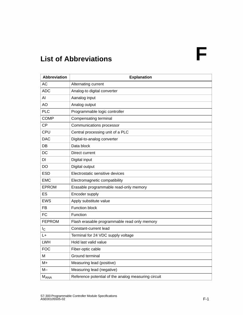
F-1S7-300 Programmable Controller Module SpecificationsA5E00105505-02
List of Abbreviations
Abbreviation Explanation
AC Alternating current
ADC Analog-to digital converter
AI Aanalog input
AO Analog output
PLC Programmable logic controller
COMP Compensating terminal
CP Communications processor
CPU Central processing unit of a PLC
DAC Digital-to-analog converter
DB Data block
DC Direct current
DI Digital input
DO Digital output
ESD Electrostatic sensitive devices
EMC Electromagnetic compatibility
EPROM Erasable programmable read-only memory
ES Encoder supply
EWS Apply substitute value
FB Function block
FC Function
FEPROM Flash erasable programmable read only memory
IC Constant-current lead
L+ Terminal for 24 VDC supply voltage
LWH Hold last valid value
FOC Fiber-optic cable
M Ground terminal
M+ Measuring lead (positive)
M– Measuring lead (negative)
MANA Reference potential of the analog measuring circuit
F

List of Abbreviations
F-2S7-300 Programmable Controller Module Specifications
A5E00105505-02
MPI Multipoint interface
OB Organization block
OP Operator panel
OS Operator system
PII Process-image input table
PIQ Process-image output table
PLC Programmable logic control
PS Power supply
QI Analog output current
QV Analog output voltage
RAM Random access memory
RL Load impedance
S + Detector lead (positive)
S– Detector lead (negative)
SF ”Group error” error LED
SFB System function block
SFC System function
SM Signal module
SSI Synchronous serial interface
TD Text display
UCM Common mode voltage
Uiso Potential difference between MANA and local ground

Glossary-1S7-300 Programmable Controller Module SpecificationsA5E00105505-02
Glossary
AddressAn address denotes a specific operand or address area; examples of this are:input I 12.1; memory word MW 25; data block DB 3.
Aggregate currentSum of the currents of all output channels on a digital output module.
Backplane busThe backplane bus is a serial data bus that is used by the modules to communi-cate with each other and to supply them with the voltage they require. The inter-connection of the modules is established by the bus connector.
Basic error limitThe basic error limit is the operational limit at 25 C, referred to the rated rangeof the analog module.
BusA bus is a transmission medium that interconnects several nodes. Datatransmission can be serial or parallel, and be performed over electric conductorsor fiber-optic cables.
Bus segmentA bus segment is a self-contained section of a serial bus system. Bus segmentsare interconnected by means of repeaters.
Common mode voltageA voltage that is common to all inputs/outputs of a group and is measuredbetween this group and any reference point (usually to ground).
Communication processorProgrammable module for communication tasks, such as networking,point-to-point connection.

Glossary
Glossary-2S7-300 Programmable Controller Module Specifications
A5E00105505-02
Comparison point When using thermocouples on analog input modules: point of known tempera-ture (for example, compensating box).
Compensating boxCompensating boxes can be used for measuring temperatures withthermocouples on analog input modules. The compensating box is acompensation circuit for compensating temperature fluctuations at theComparison point.
Complete restartWhen a CPU starts up (say, when the mode selector switch is moved fromSTOP to RUN or when the mains supply is turned on), OB 100 (Restart) isprocessed before cyclic programming processing (OB 1).With a complete restart, the Process input image is read in and the STEP 7user program is processed, starting with the first instruction in OB1.
ConfigureSelect and put together different components on a programmable logic controllerand install the requisite software and adapt to the specific use (for example, byassigning parameters to the modules).
CP Communications processor
CPUThe CPU (central processing unit) is a CPU module of the programmablelogic controller that stores and runs the user program. It contains the operatingsystem, memory, processing unit and communication interface.
Default settingThe default setting is a sensible basic setting that is used whenever no othervalue is used.
Destruction limitLimit of permitted input voltage / input current.If this limit is exceeded, the measuring accuracy may deteriorate. If thedestruction limit is exceeded by a vast amount, this may destroy the internalmeasuring circuit.

Glossary
Glossary-3S7-300 Programmable Controller Module SpecificationsA5E00105505-02
Diagnostic bufferThe diagnostic buffer is a buffered memory area in the CPU which stores thediagnostics events in the order in which they occurred.For troubleshooting, the user can read out the exact error cause in STEP 7 (PLC-> Module State) from the diagnostic buffer.
Diagnostic dataAll the diagnostics events that occurred are collected in the CPU and entered inthe Diagnostic buffer. If there is an error OB, it is started.
Diagnostic interruptModules with diagnostics capability report system errors by means of diagnosticinterrupts to the CPU. The operating system of the CPU calls OB 82 in thecourse of a diagnostic interrupt.
DiagnosticsGeneric term for System diagnostics, process error diagnosis and user-defi-ned diagnostics.
Direct accessA direct access is the direct accessing of the CPU by means of the Backplanebus to modules while avoiding the Process image.
Encoder absoluteAn encoder absolute determines the path traveled during position detection byreading a numerical value. In the case of encoders absolute with a serialinterface (SSI), path information is transferred synchronously and seriallyaccording to the SSI protocol (synchronous serial interface).
Equipotential bondingElectrical connection (equipotential bonding conductor), which brings the bodiesof electrical resources and foreign conductive bodies to an identical or approxi-mately identical potential in order to avoid interfering or hazardous voltages bet-ween these bodies.
FREEZEParameter in STEP 7 for position detection module SM 338; POS-INPUT. TheFREEZE function is a control command for freezing current encoder values ofthe SM 338 to the instantaneous value.

Glossary
Glossary-4S7-300 Programmable Controller Module Specifications
A5E00105505-02
GroundThe conductive ground whose electric potential can be set equal to zero at everypoint.In the proximity of grounding electrodes, the ground can have a potential differingfrom zero. The term ”reference ground” is frequently used to describe such cir-cumstances.
Ground, toTo ground means connect an electrically conductive part by means of a groun-ding system to the grounding electrode (one or more conductive parts having avery good contact to ground).
Hardware interruptA hardware interrupt is triggered by interrupt-triggering modules as a result of acertain event in the process (overshooting or undershooting of a limit value; amodule has completed the cyclic conversion of its channels).The hardware interrupt is reported to the CPU. In accordance with the priority ofthis interrupt, the Organization block assigned to it is scanned.
Hold last value (LWH)The module retains the last value read out before STOP mode.
Input delayParameter in STEP 7 for digital input modules. The input delay is used to sup-press injected interference. Interfering pulses from 0 ms to the set input delayare suppressed.The set input delay is subject to a tolerance, which can be taken from the techni-cal specifications of the module. A high input delay suppresses long interferingpulses, whereas a low input delay suppresses short ones.The permissible input delay depends on the length of the cable between the en-coder and the module. For example, a high input delay has to be set for longunshielded supply conductors to the encoder (longer than 100m).
Integration timeParameter in STEP 7 for analog input modules. The integration time is theinverse value of the Interference frequency suppression in ms.
Interface, multipointMPI

Glossary
Glossary-5S7-300 Programmable Controller Module SpecificationsA5E00105505-02
Interference frequency suppressionParameter in STEP 7 for analog input modules. The frequency of the AC net-work can interfere with the measured value, especially with measurements in lowvoltage ranges and with thermocouples. This parameter is used by the user tospecify the prevailing line frequency on his system.
InterruptThe SIMATIC S7 is familiar with 28 different run-time level, which govern runningof the user program. These run-time levels include interrupts such as hardwareinterrupts, among other things. When an interrupt occurs, the operating systemautomatically calls an assigned organization block in which the user can programthe reaction he wants (for example, in an FB).
Interrupt, diagnostic Diagnostic Interrupt
Interrupt, hardware Hardware interrupt
Interrupt, end-of-scan-cycle interrupt Hardware interrupt
Linearity error The linearity error identifies the maximum deviation of the measured/output valuefrom the ideal linear relationship between the measuring/output signal and thedigital value. The data is a percentage and relates to the rated range of theanalog module.
Logic blockIn a SIMATIC S7 context, a logic block is a block that contains a part of theSTEP 7 user program. By contrast, a data block only contains data. There arethe following logic blocks: organization blocks (OBs), function blocks (FBs),functions (FCs), system function block (SFBs), system functions (SFCs).
Measuring range moduleMeasuring range modules are plugged into the analog input modules for adapta-tion to different measuring ranges.

Glossary
Glossary-6S7-300 Programmable Controller Module Specifications
A5E00105505-02
Module filtering modeBy operating mode we mean:1. The selection of an operating mode of the CPU using the mode switch or thePG2. The type of program execution in the CPU3. A parameter in STEP 7 for analog input modules
Monoflop timeParameter in STEP 7 for position detection module SM 338; POS-INPUT. Themonoflop time is the time interval between 2 SSI message frames ( Encoderabsolute).
MPIThe multipoint interface (MPI) is the programmer port of the SIMATIC S7. It isused to access programmable modules ((CPUs, CPs), text displays and operatorpanel from a central point. The nodes on the MPI can communicate with eachother.
Non-isolatedIn the case of non-isolated input/output modules, the reference potentials of thecontrol and load circuit are electrically connected.
NormalizingParameter in STEP 7 for position detection module SM 338; POS-INPUT. Nor-malizing right justifies the encoder value of the encoder absolute; non-relevantplaces are discarded.
OBOrganization block
Operational limitThe operational limit is the measuring or output error of the analog module overthe entire temperature range, referred to the rated range of the analog module.
Optically isolatedWith optically isolated input/output modules, the reference potentials of the con-trol and load circuit are galvanically isolated; for example, by an optocoupler,contact assembly or repeater. Input/output circuits can be connected to commonpotential.

Glossary
Glossary-7S7-300 Programmable Controller Module SpecificationsA5E00105505-02
Organization blockOrganization blocks (OBs) form the interface between the operating system ofthe CPU and the user program. The order in which the user program isprocessed is defined in the organization blocks.
Parameters1. Tag of a Logic block2. Tag for setting the characteristics of a module (one or more per module).When delivered to the customer, each module has a practical basic setting for itsparameters, which the user can modify in STEP 7.
Process imageThe signal states of the digital input and output modules are stored in the CPU inprocess image.A distinction is made between the process-image of inputs and of outputs. Theprocess input image (PII) is read by the input modules before the operatingsystem scans the user program. The process output image (PIQ) is transferredto the output modules at the end of program scanning.
Product statusProducts having an identical order number are distinguished by their productstatus. The product status is incremented for upwards compatible extensions,modifications due to production reasons (use of new component parts andcomponents) and troubleshooting.
Programming deviceA programming device (PG) is a personal computer in a specific industry-stan-dard and compact design. A PG is completely equipped for programming SIMA-TIC programmable logic controllers.
Reaction to open thermocoupleParameter in STEP 7 for analog input modules when using Thermocouples. Thisparameter defines whether ”Overflow” (7FFFH) or ”Underflow” (8000H) is outputby the module in the event of an open thermocouple.
Reference potentialPotential from the point of view of which the voltages of the involved circuits areanalyzed and measured.

Glossary
Glossary-8S7-300 Programmable Controller Module Specifications
A5E00105505-02
Repeat accuracy The repeat accuracy identifies the maximum deviation among themeasured/output values that then occurs, when the same input signal is againapplied or the same input value specified. The repeat accuracy relates to therated range of the module and applies to the settled temperature state.
RepeaterEquipment for the amplification of bus signals and connection of bussegments over long distances.
ResolutionWith analog modules, the number of bits which represent the digitized analogvalue in binary. Resolution depends on the module and with analog inputmodules on the integration time. The precision of the resolution of a measuredvalue increases with the length of the integration time. The resolution can be asmany as 16 bits, including sign.
RetentivityData areas in data blocks, and also timers, counters and memory markers areretentive when their contents are not lost upon a complete restart or POWERDOWN.
Scan timeThe scan time is the time required by the CPU to scan the user programonce.
SegmentBus segment
SFCSystem function
Signal moduleSignal modules (SM) form the interface between the process and the program-mable logic controller. There are input modules, output modules, input/outputmodules (both digital and analog).

Glossary
Glossary-9S7-300 Programmable Controller Module SpecificationsA5E00105505-02
SmoothingParameter in STEP 7 for analog input modules. The measured values are smoo-thed by digital filtering. For specific modules it is possible to choose between no,low, medium and high smoothing. The higher the smoothing, the greater is thetime constant of the digital filter.
STARTUPThe STARTUP mode is transversed during the transition from STOP mode toRUN mode. STARTUP can be triggered by the Mode switch or followingpower-on or by means of an operator input on the programming device. With theS7-300 and M7-300, a Complete restart is performed.
Status modeThe SIMATIC S7 programmable logic controllers are familiar with the following ofstatus modes: STOP, STARTUP, RUN and STOP.
Substitute valueSubstitute values are values that can be output to the process when signal out-put modules have failed or be used in the user program instead of a process va-lue when signal input modules have failed.The substitute values can be assigned parameters by the user in STEP 7 (oldvalue retained, substitute value 0 or 1). They are values which the output(s) haveto output in the event of a CPU STOP.
System diagnosticsSystem diagnostics is the detection, analysis and reporting of errors that occurwithin the programmable logic controller. Examples of such errors are: programerrors or failures on modules. System errors can be indicated with LED displaysor in STEP 7.
System functionA system function (SFC) is a function that is integrated in the operating systemof the CPU a function that can be triggered in the STEP 7 user program, ifnecessary.
Temperature coefficientParameter in STEP 7 for analog input modules when measuring temperatureswith a resistance thermometer (RTD). The temperature coefficient you selectdepends on the resistance thermometer being used (to DIN standard).

Glossary
Glossary-10S7-300 Programmable Controller Module Specifications
A5E00105505-02
Temperature errorThe temperature error identifies the drift of the measured/output value caused bythe change in the ambient temperature of the analog module. It is specified as apercentage per Kelvin and relates to the rated range of the analog module.
Temperature errors of internal compensationThe temperature error of internal compensation only occurs during thermocouplemeasurement. It identifies the additional error which is to be taken into accountand added to the actual temperature error when ”internal comparison” mode isselected. The data is either given as a percentage relative to the physical ratedrange of the analog module or as an absolute value in C.
Two-conductor/three-conductor/four-conductor connectionMethod of connection to the module – for example, of resistancethermometers/resistors to the front connector of the analog input module or ofloads at the voltage output of an analog output module.
Two-wire transmitter/four-wire transmitterKind of transmitter (two-wire transmitter: supply (via terminals of the analog inputmodule; 4-wire transmitter: supply via separate terminals of the transmitter)
UngroundedWithout galvanic connection to ground
User programThe user program contains all the statements, tags and data for signalprocessing used to control a system or a process. It is assigned to aprogrammable module (CPU, FM, for example) and can be structured in smallerunits (blocks).
Wire-breakParameter in STEP 7. A wire-break test is used for monitoring the connectionfrom the input to the encoder and from the output to the actuator. With wire-break, the module detects a flow of current at the appropriately parameterizedinput/output.

Index-11S7-300 Programmable Controller Module SpecificationsA5E00105505-02
Index
AAccessories, D-1Active bus module, dimension drawing, C-8Actuator connection, to analog output module,
4-72Address, Glossary-1Addressing, SM 338; POS-INPUT, 5-16Aggregate current, Glossary-1Ambient conditions, mechanical, 1-10, 1-16Analog functions, STEP 7 blocks, 4-1Analog input module
causes of errors and remedies, 4-79common-mode error, 4-79configuring error, 4-79connecting resistance thermometers, 4-57connecting resistors, 4-57connecting sensor, 4-49connecting thermocouple, 4-63diagnostic interrupt, 4-44diagnostic message in measured value,
4-78diagnostic messages, 4-78diagnostics, 4-44group diagnostics, 4-44interference frequency suppression, 4-46,
A-9isolated, 4-49limit value, 4-44load voltage missing, 4-79measurement, 4-45measuring method, 4-45measuring methods and measuring ranges,
A-9measuring range, 4-45module filtering mode, 4-45non-isolated, 4-49overflow, 4-80parameter assignment error, 4-79parameters, 4-44, A-7potential difference, 4-49reaction with open thermocouple, 4-45
Analog input moduleSM 331; AI 2 x 12 bits, 4-150SM 331; AI 8 x 12 bits, 4-111SM 331; AI 8 x 13 bits, 4-105SM 331; AI 8 x 16 bits, 4-83, 4-92SM 331; AI 8 x RTD, 4-122SM 331; AI 8 x TC, 4-135smoothing of analog input values, 4-46structure of data record 1, A-8temperature coefficient, 4-46temperature unit, 4-45underflow, 4-80wire-break, 4-79, 4-80wire-break check, 4-44
Analog input modules, SM 331,channel-specific diagnostic data, B-6
Analog input/module, structure of data record1, A-41
Analog input/output moduleintegration time, 4-48measurement, 4-48measuring method, 4-48measuring range, 4-48output range, 4-48output type, 4-48parameters, 4-48, A-40SM 332; AO 2 x 12 bits, 4-177SM 334; AI 4/AO 2 x 12 bits, 4-189SM 334; AI 4/AO 2 x 8/8 bits, 4-183
Analog moduleassigning parameters, 4-43behavior, 4-34determination of measuring error/output
error, 4-38diagnostics, 4-77dimension drawing, C-17group error LED, 4-78interrupts, 4-81sequence of steps for commissioning, 4-8SF LED, 4-78supply voltage failure, 4-35

Index
Index-12S7-300 Programmable Controller Module Specifications
A5E00105505-02
Analog output channel, conversion time, 4-41Analog output module
causes of errors and remedies, 4-80connecting loads and actuators, 4-72connecting loads to current output, 4-76connecting loads to voltage output, 4-73diagnostic interrupt, 4-47diagnostic messages, 4-79diagnostics, 4-47group diagnostics, 4-47isolated, 4-72load voltage missing, 4-80M short-circuit, 4-80non-isolated, 4-72output methods and output ranges, A-37output range, 4-47output type, 4-47parameter assignment error, 4-80parameters, 4-47response time, 4-42response with CPU-STOP, 4-47setting substitute values, A-37settling time, 4-42SM 332; AO 4 x 12 bits, 4-171SM 332; AO 4 x 16 bits, 4-166SM 332; AO 8 x 12 bits, 4-160structure of data record 1, A-36
Analog output modules, parameters, A-35Analog output modules, SM 332,
channel-specific diagnostic data, B-6Analog value
conversion, 4-10sign, 4-10
Analog value representation, 4-10binary representation of input ranges, 4-13binary representation of output ranges, 4-26for current measuring ranges, 4-16–4-18for current output ranges, 4-30–4-33for resistance type transmitters, 4-17for RTD Resistance Temperature Detectors,
4-17, 4-18, 4-19, 4-20, 4-21, 4-22, 4-23,4-24, 4-25
for RTD resistance temperature detectors,4-19, 4-20
for voltage measuring ranges, 4-14–4-16for voltage output ranges, 4-28–4-31
Analog-to-digital conversion, 4-39
ApprovalCE, 1-2CSA, 1-3FM, 1-4Shipbuilding, 1-4UL, 1-3
Approvals, Standards, 1-2Auxiliary voltage missing, SM 338;
POS-INPUT, 5-20
BBackplane bus, Glossary-1Backup battery, 1-9
shipping and storage conditions, 1-8Basic error limit, 4-38Basic knowledge, iiiBattery. See backup batteryBehavior, SM 321; DI 16 x 24 VDC, 3-28Bus segment, Glossary-1Bytes 0 and 1
of diagnostic data, B-2of diagnostic data for SM 338; POS-INPUT,
B-7Bytes 2 and 3, of diagnostic data, B-3Bytes 2 to 7, of diagnostic data for SM 338;
POS-INPUT, B-8Bytes 4 to 7, of diagnostic data, B-4Bytes 8 to 10, of diagnostic data for SM 338;
POS-INPUT, B-8
Index
Index-13S7-300 Programmable Controller Module SpecificationsA5E00105505-02
CCables, for analog signals, 4-49, 4-72Causes of error and remedial measures
SM 321; DI 16 x 24 VDC, 3-30SM 322; DO 8 x 24 VDC/0.5 A, 3-78
Causes of errors and remediesanalog input module, 4-79analog output module, 4-80
CE, Approval, 1-2Changes, in manual, iiiChannel error, SM 338; POS-INPUT, 5-20Channel information present, SM 338;
POS-INPUT, 5-20Channel-specific diagnostics, B-5Climatic conditions, 1-11Code type, SM 338; POS-INPUT, 5-15Commissioning analog modules, sequence of
steps, 4-8Commissioning digital modules, sequence of
steps, 3-10Common mode voltage, Glossary-1Common-mode error, analog input module,
4-79Communication processor, Glossary-1Comparison point, 4-67, Glossary-2Compensating box, 4-65
connecting, 4-66Compensation
external, 4-65internal, 4-64, 4-66
Complete restart, Glossary-2Configuration error, SM 338; POS-INPUT, 5-20Configure, Glossary-2Configuring error, analog input module, 4-79Conversion time
analog input channels, 4-39analog output channel, 4-41
Converting, analog values, 4-10CP, Glossary-1CPU, Glossary-2CSA, Approval, 1-3Current sensors, connecting, 4-55
DData record, for diagnostic data, B-1Data record 1
analog input module configuration, A-8analog output module configuration, A-36digital input module configuration, A-4digital output module configuration, A-6structure for SM 331; AI 8 x 13 bits, A-27structure for SM 331; AI 8 x RTD, A-12structure for SM 331; AI 8 x TC, A-20structure of analog input/output module,
A-41Data record 128
structure for SM 331; AI 8 x RTD, A-13structure for SM 331; AI 8 x TC, A-21
Data record1, Configuration SM 332; AO 8 x12 bits, A-39
Data records, for parameters, A-2Default setting, Glossary-2Degree of protection, 1-12
IP 20, 1-12Destruction limit, Glossary-2Diagnostic buffer, Glossary-3Diagnostic data, Glossary-3
bytes 0 and 1, B-2bytes 2 and 3, B-3bytes 4 to 7, B-4channel-specific, B-5channel-specific, for analog input modules
of SM 331, B-6channel-specific, for analog output modules
of SM 332, B-6channel-specific, for SM 321; DI 16 x 24
VDC, B-5channel-specific, for SM 322; DO 8 x 24
VDC/0.5 A, B-5channel-specific, for SM 338; POS-INPUT,
B-8data record, B-1SM 338; POS-INPUT, B-7
Diagnostic data for SM 338; POS-INPUT,bytes 0 and 1, B-7
Diagnostic data of SM 338; POS-INPUTBytes 2 to 7, B-8Bytes 8 to 10, B-8
Diagnostic interruptanalog input module, 4-44analog output module, 4-47of analog modules, 4-81SM 321; DI 16 x 24 VDC, 3-26, 3-31SM 322; DO 8 x 24 VDC/0.5 A, 3-75, 3-79SM 338; POS-INPUT, 5-21

Index
Index-14S7-300 Programmable Controller Module Specifications
A5E00105505-02
Diagnostic interrupt enable, SM 338;POS-INPUT, 5-14
Diagnostic messages, 3-12, 4-77, 5-18of analog input modules, 4-78of analog output modules, 4-79reading out, 3-13, 4-78, 5-18SM 322; DO 8 x 24 VDC/0.5 A, 3-77
Diagnosticsanalog input module, 4-44analog output module, 4-47of analog modules, 4-77of digital modules, 3-12SM 321; DI 16 x 24 VDC, 3-26, 3-28SM 338; POS-INPUT, 5-18, 5-19system, Glossary-9
Diagnostics entry, 4-36Digital input module
SM 321; DI 16 x 24 VDC, 3-18SM 321; DI 16 x 24 VDC High Speed, 3-21SM 321; DI 16 x 24 VDC; source input,
3-33SM 321; DI 16 x 24 VDC; with hardware
and diagnostic interrupts, 3-23SM 321; DI 16 x 48-125 VDC, 3-37SM 321; DI 16 x AC 120/230 V, 3-39SM 321; DI 16 x UC 24/48 V, 3-35SM 321; DI 32 x 120 VAC, 3-16SM 321; DI 32 x 120/230 VAC ISOL, 3-43SM 321; DI 32 x 24 VDC, 3-13SM 321; DI 8 x 120/230 VAC, 3-41structure of data record 1, A-4
Digital input modules, parameters, A-3Digital input/output module
SM 323; DI 16/DO 16 x 24 VDC/0.5 A,3-110
SM 323; DI 8/DO 8 x 24 VDC/0.5 A, 3-114Digital module
assigning parameters, 3-11diagnostics, 3-12dimension drawing, C-17group error LED, 3-13sequence of steps for commissioning, 3-10SF LED, 3-13
Digital output moduleparameters, A-5SM 322; DO 16 x 120/230 VAC/1 A, 3-64SM 322; DO 16 x 24 VDC/0.5 A, 3-52SM 322; DO 16 x 24 VDC/0.5 A High
Speed, 3-55SM 322; DO 16 x 24/48 VUC, 3-58SM 322; DO 32 x 120 VAC/1.0 A, 3-48SM 322; DO 32 x 120/230 VAC/2 A ISOL ,
3-86SM 322; DO 32 x 24 VDC/0.5 A, 3-45SM 322; DO 8 x 120/230 VAC/2 A, 3-83SM 322; DO 8 x 24 VDC/0.5 A with
diagnostic interrupt, 3-70SM 322; DO 8 x 24 VDC/2 A, 3-67SM 322; DO 8 x 48-125 VDC/1.5 A, 3-80structure of data record 1, A-6
Dimension drawing, active bus module, C-8Dimension drawings, C-1
analog module, C-17digital module, C-17IM 361, C-14interface module, C-14power supply module PS 307, C-9PS 307, C-9rail, C-2RS 485 repeater, C-20shield connecting element, C-18signal module, C-17SIMATIC TOP connect, C-19
Direct access, Glossary-3Documentation package, vDummy module, DM 370, 5-5

Index
Index-15S7-300 Programmable Controller Module SpecificationsA5E00105505-02
EElectromagnetic compatibility, 1-6Encoder absolute, Glossary-3Encoder absolute (SSI), SM 338; POS-INPUT,
5-14Encoder error, SM 338; POS-INPUT, 5-20Encoder value detection, clocked, 5-11Environmental conditions, 1-9
extended, 1-14Outdoor modules, 1-16
EPROM errorSM 321; DI 16 x 24 VDC, 3-30SM 322; DO 8 x 24 VDC/0.5 A, 3-78
Equipotential bonding, Glossary-3Error, of an analog module, 4-38Error causes and troubleshooting, SM 338;
POS-INPUT, 5-20Extended environmental conditions, 1-14External auxiliary voltage missing, SM 321; DI
16 x 24 VDC, 3-30
FFM, Approval, 1-4Four-conductor connection, 4-58, Glossary-10Four-wire transmitter, Glossary-10Four-wire transmitters, 4-57FREEZE, Glossary-3Freeze function, SM 338; POS-INPUT, 5-13,
5-15Fuse blown
SM 321; DI 16 x 24 VDC, 3-30SM 322; DO 8 x 24 VDC/0.5 A, 3-78
GGround, Glossary-4Grounded operation, RS 485 repeater, 7-4Group diagnostics
analog input module, 4-44analog output module, 4-47
Group error LEDanalog module, 4-78digital module, 3-13SM 338; POS-INPUT, 5-18
HHardware interrupt, Glossary-4
End of scan cycle, 4-83SM 321; DI 16 x 24 VDC, 3-26, 3-32when limit exceeded, 4-82
Hardware interrupt lost, SM 321; DI 16 x 24VDC, 3-30, 3-32
Hold last value, SM 322; DO 8 x 24 VDC/0.5A, 3-75
IIdentifiers for Australia, 1-4IEC 61131, 1-4IM 360
dimension drawing, C-14interface module, 6-3
IM 361, interface module, 6-5IM 365
dimension drawing, C-16interface module, 6-7
Input delay, Glossary-4SM 321; DI 16 x 24 VDC, 3-26
Insulation test, 1-12Integration time, Glossary-4
analog input/output module, 4-48Interface module, 6-1
dimension drawing, C-14IM 360, 6-3IM 361, 6-5IM 365, 6-7
Interferencepulse-shaped, 1-6sinusoidal, 1-7
Interference frequency suppression,Glossary-5analog input module, 4-46, A-9SM 331; AI 8 x RTD, A-16SM 331; AI 8 x TC, A-24, A-28
Internal auxiliary voltage missing, SM 321; DI16 x 24 VDC, 3-30
Internal compensation, Temperature error,Glossary-10
Internal error, SM 338; POS-INPUT, 5-20Interrupt, Glossary-5

Index
Index-16S7-300 Programmable Controller Module Specifications
A5E00105505-02
Interrupt-triggering channels, SM 321; DI 16 x24 VDC, 3-32
Interruptsenabling, 3-31, 3-79, 4-81, 5-21of analog modules, 4-81SM 321; DI 16 x 24 VDC, 3-31SM 322; DO 8 x 24 VDC/0.5 A, 3-79SM 338; POS-INPUT, 5-21
IP 20, 1-12Isochrone mode, SM 338, 5-9Isolated measuring sensors, 4-50
connecting, 4-50
LLack of encoder supply, SM 321; DI 16 x 24
VDC, 3-30Limit value, analog input module, 4-44Linearity error, Glossary-5Load connection, to analog output module,
4-72Load connection to current output, to analog
output module, 4-76Load connection to voltage output, to analog
output module, 4-73Load voltage missing
analog input module, 4-79analog output module, 4-80
Logic block, Glossary-5LWH, Glossary-4
MM short-circuit, analog output module, 4-80Manual, purpose, iiiManual changes, iiiManual package, vMeasurement
analog input module, 4-45analog input/output module, 4-48
Measuring methodanalog input channels, 4-31analog input module, 4-45, A-9analog input/output module, 4-48SM 331; AI 8 x 13 bits, A-28SM 331; AI 8 x RTD, A-16SM 331; AI 8 x TC, A-25
Measuring rangeanalog input channels, 4-31analog input module, 4-45, A-9analog input/output module, 4-48SM 331; AI 8 x 13 bits, A-28SM 331; AI 8 x RTD, A-16SM 331; AI 8 x TC, A-25
Measuring range module, 4-31replugging, 4-32
Measuring sensors, isolated, 4-50Module Classes, ID, B-2Module filtering mode, Glossary-6
analog input module, 4-45Module malfunction, SM 338; POS-INPUT,
5-20Module overview, 4-3
digital modules, 3-4other signal modules, 5-2SIMATIC TOP connect/...TPA, 8-2
Modules, shipping and storage conditions, 1-8Monoflop time, Glossary-6
SM 338; POS-INPUT, 5-15MPI, Glossary-6
NNavigation, through the manual, viNo external auxiliary voltage, SM 322; DO 8 x
24 VDC/0.5 A, 3-78No internal auxiliary voltage, SM 322; DO 8 x
24 VDC/0.5 A, 3-78No load voltage L+, SM 322; DO 8 x 24
VDC/0.5 A, 3-75, 3-78Non-isolated, Glossary-6Non-isolated sensors, 4-52
connecting, 4-52Normalizing, Glossary-6
SM 338; POS-INPUT, 5-12, 5-15

Index
Index-17S7-300 Programmable Controller Module SpecificationsA5E00105505-02
OOB, Glossary-7OB 40, 3-32, 4-82
start information, 4-82OB 82, 3-31, 3-79, 4-81Operating conditions, 1-9Operating mode
of CPU, 4-34SM 331; AI 8 x RTD, A-16SM 331; AI 8 x TC, A-24
Operational limit, 4-38, Glossary-6Optically isolated, Glossary-6Order Number
6ES7 338-4BC01-0AB0, 5-86ES7 370-0AA01-0AA0, 5-56ES7 374-2XH01-0AA0, 5-3
Order number6ES7 305-1BA80-0AA0, 2-26ES7 307-1BA00-0AA0, 2-66ES7 307-1EA00-0AA0, 2-106ES7 307-1EA80-0AA0, 2-106ES7 307-1KA00-0AA0, 2-156ES7 321-1BH02-0AA0, 3-186ES7 321-1BH10-0AA0, 3-216ES7 321-1BH50-0AA0, 3-336ES7 321-1BH82-0AA0, 3-186ES7 321-1BL00-0AA0, 3-136ES7 321-1BL80-0AA0, 3-136ES7 321-1CH00-0AA0, 3-356ES7 321-1CH80-0AA0, 3-376ES7 321-1EL00-0AA0, 3-166ES7 321-1FF01-0AA0, 3-416ES7 321-1FF10-0AA0, 3-436ES7 321-1FF81-0AA0, 3-416ES7 321-1FH00-0AA0, 3-396ES7 321-7BH00-0AB0, 3-236ES7 321-7BH80-0AB0, 3-236ES7 322-1BF01-0AA0, 3-676ES7 322-1BH01-0AA0, 3-526ES7 322-1BH10-0AA0, 3-556ES7 322-1BH81-0AA0, 3-526ES7 322-1BL00-0AA0, 3-456ES7 322-1CF80-0AA0, 3-806ES7 322-1EL00-0AA0, 3-486ES7 322-1FF01-0AA0, 3-836ES7 322-1FF81-0AA0, 3-836ES7 322-1FH00-0AA0, 3-646ES7 322-1HF01-0AA0, 3-956ES7 322-1HF10-0AA0, 3-1056ES7 322-1HF80-0AA0, 3-1056ES7 322-1HH01-0AA0, 3-926ES7 322-5FF00-0AB0, 3-86
6ES7 322-5GH00-0AB0, 3-586ES7 322-5HF00-0AB0, 3-986ES7 322-8BF00-0AB0, 3-706ES7 322-8BF80-0AA0, 3-706ES7 323-1BH01-0AA0, 3-1146ES7 323-1BH81-0AA0, 3-1146ES7 323-1BL00-0AA0, 3-1106ES7 331-1KF00-0AB0, 4-1056ES7 331-7KB02-0AB0, 4-1506ES7 331-7KB82-0AB0, 4-1506ES7 331-7KF02-0AB0, 4-1116ES7 331-7NF00-0AB0, 4-836ES7 331-7NF10-0AB0, 4-926ES7 331-7PF00-0AB0, 4-1226ES7 331-7PF10-0AB0, 4-1356ES7 332-5HB01-0AB0, 4-1776ES7 332-5HB81-0AB0, 4-1776ES7 332-5HD01-0AB0, 4-1716ES7 332-5HF00-0AB0, 4-1606ES7 332-7ND01-0AB0, 4-1666ES7 334-0CE01-0AA0, 4-1836ES7 334-0KE00-0AB0, 4-1896ES7 360-3AA01-0AA0, 6-36ES7 361 3CA01-0AA0, 6-56ES7 365-0BA01-0AA0, 6-76ES7 972-0AA01-0XA0, 7-2
Organization block (OB), Glossary-7Outdoor modules, 1-14Output analog values, STEP 7 blocks, 4-1Output method, analog output module, A-37Output range
analog input/output module, 4-48analog output module, 4-47, A-37
Output typeanalog input/output module, 4-48analog output module, 4-47
Overflow, analog input module, 4-80

Index
Index-18S7-300 Programmable Controller Module Specifications
A5E00105505-02
PParameter assignment
for analog modules, 4-43for digital modules, 3-11in user program, A-1
Parameter assignment erroranalog input module, 4-79analog output module, 4-80
Parameterization error, SM 338; POS-INPUT,5-20
Parameterization missing, SM 338;POS-INPUT, 5-20
Parameters, Glossary-7analog input module, 4-44, A-7analog input/output module, 4-48, A-40analog output module, 4-47analog output modules, A-35data records, A-2digital input modules, A-3digital output module, A-5dynamic, 3-11, 4-43modifying in user program, 3-11, 4-43SM 321; DI 16 x 24 VDC, 3-26SM 322; DO 8 x 24 VDC/0.5 A, 3-75SM 331; AI 8 x RTD, A-11SM 331; AI 8 x TC, A-19SM 332; AO 8 x 12 bits, A-38SM 338; POS-INPUT, 5-14static, 3-11, 4-43
Parameters, wrongSM 321; DI 16 x 24 VDC, 3-30SM 338; POS-INPUT, 5-20
PARM_MOD, SFC 57, A-2Pin assignment, RS 485 repeater, 7-7POS input module SM 338, 5-8Position detection module, SM 338;
POS-INPUT, 5-8Potential difference, with analog input modules,
4-49Power supply module, 2-1
dimension drawing, C-9PS 305 2 A, 2-2PS 307 10 A, 2-15PS 307 2 A, 2-6PS 307 5 A, 2-10
Process image, Glossary-7Product status, Glossary-7Programming device (PG), Glossary-7Protection class, 1-12PS 307, dimension drawing, C-9Pulse edge, 3-26
Pulse-shaped interference, 1-6
RRadio interference, emission of, 1-7Rail for the ”Insert and Remove” function,
dimension drawing, C-7Rails, dimension drawing, C-2RAM error
SM 321; DI 16 x 24 VDC, 3-30SM 322; DO 8 x 24 VDC/0.5 A, 3-78
Rated voltages, 1-13Reaction to open thermocouple, SM 331; AI 8
x TC, A-26Read analog values, STEP 7 blocks, 4-1Reference junction temperature with
thermocouples, compensating, 4-64Reference potential, Glossary-7Relay output module
SM 322; DO 16 x Rel. 120/230 VAC, 3-92SM 322; DO 8 x Rel. 230 VAC, 3-95SM 322; DO 8 x Rel. 230 VAC/5 A, 3-105SM 322; DO 8 x Rel. 230 VAC/5A, 3-98
Repeat accuracy, Glossary-8Repeater, Glossary-8
See also RS 485-RepeaterResistance thermometer connection, to
analog input module, 4-57Resistor connection, to analog input module,
4-57Resolution, 4-10, Glossary-8Response time, 4-42Response with CPU-STOP, analog output
module, 4-47Retentivity, Glossary-8RS 485 repeater
Appearance, 7-3application, 7-2definition, 7-2dimension drawing, C-20grounded operation, 7-4rules, 7-2ungrounded operation, 7-4
RS 485-Repeater, 7-1grounded, 7-4ungrounded, 7-4

Index
Index-19S7-300 Programmable Controller Module SpecificationsA5E00105505-02
SScan time, Glossary-8
analog input channels, 4-39analog output channels, 4-41
Screw-type terminals, SIMATIC TOPconnect/...TPA, 8-10
Sensor connection, to analog input module,4-49
Sensors, non-isolated, 4-52Settling time, 4-42SF LED
analog module, 4-78digital module, 3-13SM 338; POS-INPUT, 5-18
SFC, Glossary-8, Glossary-9SFC 51, 3-31, 3-79, 4-81SFC 55 WR_PARM, A-2SFC 56 WR_DPARM, A-2SFC 57 PARM_MOD, A-2SFC 59, 3-31, 3-79, 4-81Shield connecting element, dimension drawing,
C-18Shipbuilding, Approval, 1-4Short-circuit to L+, SM 322; DO 8 x 24
VDC/0.5 A, 3-75, 3-78Short-circuit to M, SM 322; DO 8 x 24 VDC/0.5
A, 3-75, 3-78Sign, analog value, 4-10Signal module, Glossary-8
dimension drawing, C-17SIMATIC Outdoor modules, 1-14SIMATIC TOP connect
components, 8-12connection for 2A modules, 8-18dimension drawing, C-19one-conductor connection, 8-14selecting components, 8-13three-conductor connection, 8-16wiring 32-channel digital modules, 8-8
SIMATIC TOP connect TPAcomponent selection, 8-20connection example, 8-24multiplier terminal, 8-21shield connection, 8-23terminal allocation to analog module, 8-22terminal assignment, 8-21
SIMATIC TOP connect/...TPAadvantages of using, 8-3components, 8-3configuration, 8-2connecting cable, 8-4connectors, 8-4mounting terminal block and connecting
cable, 8-10screw-type terminals, 8-10spring-loaded terminals, 8-10wiring, 8-4wiring actuators/sensors to terminal block,
8-10wiring rules, 8-7wiring the front connector module, 8-6wiring with modules..., 8-3
Simulator module, SM 374; IN/OUT 16, 5-3Sinusoidal interference, 1-7SM 321; DI 16 x 24 VDC
channel-specific diagnostic data, B-5diagnostic interrupt, 3-31diagnostics, 3-26EPROM error, 3-30external auxiliary voltage missing, 3-30fuse blown, 3-30input delay, 3-26internal auxiliary voltage missing, 3-30interrupts, 3-31lack of encoder supply, 3-30redundant encoder supply, 3-24voltage type, 3-26watchdog, 3-30

Index
Index-20S7-300 Programmable Controller Module Specifications
A5E00105505-02
SM 321; DI 16 x 24 VDCcauses of error and remedial measures,
3-30diagnostic interrupt, 3-26hardware interrupt, 3-26, 3-32hardware interrupt lost, 3-30, 3-32interrupt-triggering channels, 3-32parameters, wrong, 3-30RAM error, 3-30
SM 322; DO 8 x 24 VDC/0.5 Aapply substitute value ”1”, 3-75causes of error and remedial action, 3-78channel-specific diagnostic data, B-5diagnostic interrupt, 3-75, 3-79diagnostic messages, 3-77EPROM error, 3-78fuse blown, 3-78hold last value, 3-75interrupts, 3-79no external auxiliary voltage, 3-78no internal auxiliary voltage, 3-78no load voltage L+, 3-75, 3-78parameters, 3-75RAM error, 3-78short-circuit to L+, 3-75, 3-78short-circuit to M, 3-75, 3-78substitute value application, 3-75watchdog, 3-78wire-break, 3-75, 3-78
SM 331; AI 8 x 13 bitsInterference frequency suppression, A-28Measuring methods and measuring ranges,
A-28structure of data record 1, A-27
SM 331; AI 8 x RTDinterference frequency suppression, A-16operating modes, A-16parameters, A-11smoothing, A-18structure of data record 1, A-12structure of data record 128, A-13Temperature coefficient, A-18
SM 331; AI 8 x RTD x 24 bits, measuringmethods and measuring ranges, A-16
SM 331; AI 8 x TCinterference frequency suppression, A-24measuring methods and measuring ranges,
A-25operating modes, A-24parameters, A-19reaction to open thermocouple, A-26smoothing, A-26structure of data record 1, A-20structure of data record 128, A-21
SM 332; AO 8 x 12 bitsParameters, A-38Structure of data record 1, A-39
SM 338detection of encoder value, 5-11Encoder value detection, 5-11Functions, 5-11isochrone mode, 5-9POS input module, 5-8

Index
Index-21S7-300 Programmable Controller Module SpecificationsA5E00105505-02
SM 338; POS-INPUTaddressing, 5-16auxiliary voltage missing, 5-20causes of errors and troubleshooting, 5-20channel error, 5-20channel information present, 5-20channel-specific diagnostic data, B-8code type, 5-15configuration error, 5-20diagnostic data, B-7diagnostic interrupt, 5-21diagnostic interrupt enable, 5-14diagnostics, 5-18encoder absolute (SSI), 5-14encoder error, 5-20external error, 5-20Freeze function, 5-13, 5-15group error LED, 5-18internal error, 5-20interrupts, 5-21module malfunction, 5-20monoflop time, 5-15Normalizing, 5-12normalizing, 5-15parameterization error, 5-20parameterization missing, 5-20parameters, wrong, 5-20SF LED, 5-18transmission rate, 5-15watchdog tripped, 5-20
Smoothing, Glossary-9SM 331; AI 8 x RTD, A-18SM 331; AI 8 x TC, A-26
Smoothing analog input values, 4-40analog input module, 4-46
Spare parts, D-1Spring-loaded terminals, SIMATIC TOP
connect/...TPA, 8-10Standards and approvals, 1-2Startup, Glossary-9Status mode, Glossary-9STEP 7 blocks, for analog functions, 4-1Substitute value, Glossary-9
analog output module, A-37Substitute value ”1” application, SM 322; DO 8
x 24 VDC/0.5 A, 3-75Substitute value application, SM 322; DO 8 x
24 VDC/0.5 A, 3-75Supply voltage failure, of the analog module,
4-35System diagnostics, Glossary-9System function (SFC), Glossary-9
TTechnical specifications, RS 485 repeater, 7-7Temperature coefficient, Glossary-9
analog input module, 4-46SM 331; AI 8 x RTD, A-18
Temperature error, Glossary-10Temperature errors of internal compensation,
Glossary-10Temperature measurement, SM 331; AI 8 x 13
bit, A-27Temperature unit, Analog input module, 4-45Test voltages, 1-12Thermo emf, 4-63Thermocouple
design, 4-63open, reaction to, Glossary-7principle of operation, 4-63
Thermocouple connection, to analog inputmodule, 4-63
Three-conductor connection, 4-59,Glossary-10
Transmission rate, SM 338; POS-INPUT, 5-15Two-conductor connection, 4-59, Glossary-10Two-wire transmitter, Glossary-10Two-wire transmitters, 4-56

Index
Index-22S7-300 Programmable Controller Module Specifications
A5E00105505-02
UUL, Approval, 1-3Underflow, analog input module, 4-80Ungrounded operation, RS 485 repeater, 7-4Use in an industrial environment, 1-5Use in residential environments, 1-5Use of the ET 200 / S7-300 in Zone 2, 1-17User program, Glossary-10
parameter assignment in, A-1
VVibrations, 1-10Voltage sensors, connecting, 4-54Voltage type, SM 321; DI 16 x 24 VDC, 3-26
WWatchdog
SM 321; DI 16 x 24 VDC, 3-30SM 322; DO 8 x 24 VDC/0.5 A, 3-78
Watchdog tripped, SM 338; POS-INPUT, 5-20Wire-break, Glossary-10
Analog input module, 4-79analog input module, 4-80SM 322; DO 8 x 24 VDC/0.5 A, 3-75, 3-78
Wire-break check, analog input module, 4-44WR_DPARM, SFC 56, A-2WR_PARM, SFC 55, A-2