s7-300 programmable controller installation and hardware · correct usage trademarks. iii s7-300,...
TRANSCRIPT
Preface, Contents
Product Overview 1
Mechanical Configuration 2
Addressing the S7-300 Modules 3
Electrical Configuration 4
Installing an S7-300 5
Wiring an S7-300 6Configuring an MPI or PROFIBUS Subnet 7Preparing an S7-300 for Operation and Start-up of PROFIBUS-DP 8Changing the Backup Battery/Rechargeable Battery, Moduleand Fuses 9
CPUs 10CPU 315-2 DP as DP Master/DP Slave 11Cycle Time and Response Timeof the S7-300 12
Appendices
Glossary, Index
Edition 2
EWA 4NEB 710 6078-02a
S7-300 Programmable ControllerInstallation and Hardware
Manual
SIMATIC
This Manual is Part of the Documentation Packagewith the Order Number:
6ES7 398-8AA02-8BA0
iiS7-300, Installation and Hardware
EWA 4NEB 710 6078 02
This manual contains notices which you should observe to ensure your own personal safety, aswell as to protect the product and connected equipment. These notices are highlighted in themanual by a warning triangle and are marked as follows according to the level of danger:
!Danger
indicates that death, severe personal injury or substantial property damage will result if properprecautions are not taken.
!Warning
indicates that death, severe personal injury or substantial property damage can result if properprecautions are not taken.
!Caution
indicates that minor personal injury or property damage can result if proper precautions are not taken.
Note
draws your attention to particularly important information on the product, handling the product, orto a particular part of the documentation.
Only qualified personnel should be allowed to install and work on this equipment. Qualifiedpersons are defined as persons who are authorized to commission, to ground, and to tag circuits,equipment, and systems in accordance with established safety practices and standards.
Note the following:
!Warning
This device and its components may only be used for the applications described in the catalog or thetechnical description, and only in connection with devices or components from other manufacturerswhich have been approved or recommended by Siemens.
This product can only function correctly and safely if it is transported, stored, set up, and installedcorrectly, and operated and maintained as recommended.
SIMATIC and SIMATIC NET are registered trademarks of SIEMENS AG.
Third parties using for their own purposes any other names in this document which refer to trade-marks might infringe upon the rights of the trademark owners.
We have checked the contents of this manual for agreement with thehardware and software described. Since deviations cannot be pre-cluded entirely, we cannot guarantee full agreement. However, thedata in this manual are reviewed regularly and any necessarycorrections included in subsequent editions. Suggestions for im-provement are welcomed.
Technical data subject to change. Siemens AG 1994
Disclaimer of LiabilityCopyright Siemens AG 1994 All rights reserved
The reproduction, transmission or use of this document or itscontents is not permitted without express written authority.Offenders will be liable for damages. All rights, including rightscreated by patent grant or registration of a utility model or design, arereserved.
Siemens AGAutomation GroupIndustrial Automation SystemsP.O. Box 4848, D-90327 Nuremberg
Siemens Aktiengesellschaft
Safety Guidelines
Qualified Personnel
Correct Usage
Trademarks
iiiS7-300, Installation and HardwareEWA 4NEB 710 6078-02a
Preface
The information contained in this manual will help you with the following:
Install and wire an S7-300 programmable controller, and
Look up operator entries, functional descriptions and the technical speci-fications relevant to the S7-300’s CPUs.
You will find the function descriptions and technical specifications for thesignal modules, power supply modules and interface modules in the Mod-ule Specifications Reference Manual.
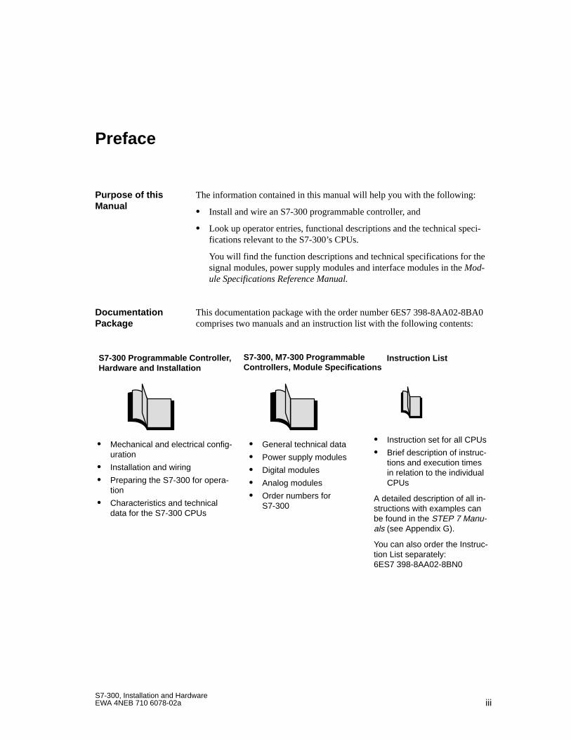
This documentation package with the order number 6ES7 398-8AA02-8BA0comprises two manuals and an instruction list with the following contents:
S7-300 Programmable Controller ,Hardware and Installation
Mechanical and electrical config-uration
Installation and wiring
Preparing the S7-300 for opera-tion
Characteristics and technicaldata for the S7-300 CPUs
General technical data
Power supply modules
Digital modules
Analog modules
Order numbers forS7-300
S7-300, M7-300 Programmable Controllers, Module Specifications
Instruction List
Instruction set for all CPUs
Brief description of instruc-tions and execution timesin relation to the individualCPUs
A detailed description of all in-structions with examples canbe found in the STEP 7 Manu-als (see Appendix G).
You can also order the Instruc-tion List separately:6ES7 398-8AA02-8BN0
Purpose of thisManual
DocumentationPackage
ivS7-300, Installation and Hardware
EWA 4NEB 710 6078-02a
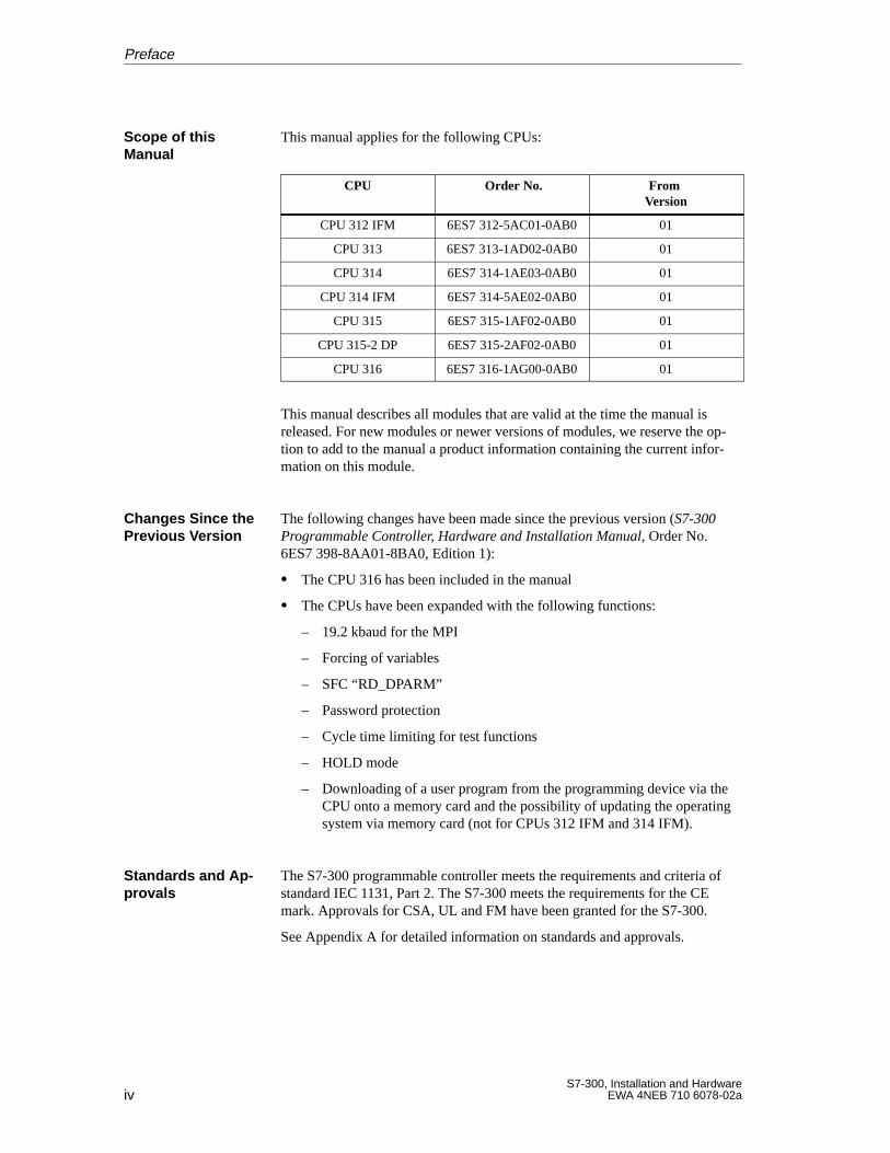
This manual applies for the following CPUs:
CPU Order No. From Version
CPU 312 IFM 6ES7 312-5AC01-0AB0 01
CPU 313 6ES7 313-1AD02-0AB0 01
CPU 314 6ES7 314-1AE03-0AB0 01
CPU 314 IFM 6ES7 314-5AE02-0AB0 01
CPU 315 6ES7 315-1AF02-0AB0 01
CPU 315-2 DP 6ES7 315-2AF02-0AB0 01
CPU 316 6ES7 316-1AG00-0AB0 01
This manual describes all modules that are valid at the time the manual isreleased. For new modules or newer versions of modules, we reserve the op-tion to add to the manual a product information containing the current infor-mation on this module.
The following changes have been made since the previous version (S7-300Programmable Controller, Hardware and Installation Manual, Order No.6ES7 398-8AA01-8BA0, Edition 1):
The CPU 316 has been included in the manual
The CPUs have been expanded with the following functions:
– 19.2 kbaud for the MPI
– Forcing of variables
– SFC “RD_DPARM”
– Password protection
– Cycle time limiting for test functions
– HOLD mode
– Downloading of a user program from the programming device via theCPU onto a memory card and the possibility of updating the operatingsystem via memory card (not for CPUs 312 IFM and 314 IFM).
The S7-300 programmable controller meets the requirements and criteria ofstandard IEC 1131, Part 2. The S7-300 meets the requirements for the CEmark. Approvals for CSA, UL and FM have been granted for the S7-300.
See Appendix A for detailed information on standards and approvals.
Scope of thisManual
Changes Since thePrevious V ersion
Standards and Ap -provals
Preface
vS7-300, Installation and HardwareEWA 4NEB 710 6078-02a
The SIMATIC S7-300 is an environmentally-friendly product!The essential features of the SIMATIC S7-300 include:
A halogen-free flameproofing of the plastic housing despite its high levelof fireproofing
Laser labeling (that is, no paper labels)
Plastics materials labeled in accordance with DIN 54840
Reduction in materials used thanks to more compact design and fewercomponents through integration in ASICs
The SIMATIC S7-300 can be recycled thanks to the low level of pollutants inits equipment.
Please contact the following address for environmentally-friendly recyclingand disposal of your old SIMATIC equipment:
Siemens AktiengesellschaftAnlagenbau und Technische DienstleistungenATD TD 3 KreislaufwirtschaftPostfach 32 40D-91050 Erlangen
Telephone: ++ 49 91 31/7-3 36 98Telefax: ++ 49 91 31/7-2 66 43
This Siemens service department provides a comprehensive and flexible dis-posal system with customized advice at a fixed price. After disposal, youreceive a breakdown of the dismantling procedure with information on theproportions of materials and the relevant material record documentation.
Recycling and Dis -posal
Preface
viS7-300, Installation and Hardware
EWA 4NEB 710 6078-02a
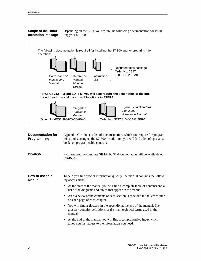
Depending on the CPU, you require the following documentation for instal-ling your S7-300:
Hardware andInstallation,Manual
ReferenceManual ModuleSpecs.
InstructionList
Documentation packageOrder No. 6ES7398-8AA02-0BA0
The following documentation is required for installing the S7-300 and for preparing it foroperation:
For CPUs 312 IFM and 314 IFM, you will also require the description of the inte -grated functions and the control functions in STEP 7:
IntegratedFunctionsManual
System and StandardFunctionsReference Manual
Order No. 6ES7 398-8CA00-8BA0 Order No. 6ES7 810-4CA02-4BR0
Appendix G contains a list of documentation, which you require for program-ming and starting up the S7-300. In addition, you will find a list of specialistbooks on programmable controls.
Furthermore, the complete SIMATIC S7 documentation will be available onCD-ROM.
To help you find special information quickly, the manual contains the follow-ing access aids:
At the start of the manual you will find a complete table of contents and alist of the diagrams and tables that appear in the manual.
An overview of the contents of each section is provided in the left columnon each page of each chapter.
You will find a glossary in the appendix at the end of the manual. Theglossary contains definitions of the main technical terms used in themanual.
At the end of the manual you will find a comprehensive index whichgives you fast access to the information you need.
Scope of the Docu-mentation Package
Documentation forProgramming
CD-ROM
How to use thisManual
Preface
viiS7-300, Installation and HardwareEWA 4NEB 710 6078-02a
Please contact your local Siemens representative if you have any queriesabout the products described in this manual. A list of Siemens representativesworldwide is contained in the appendix to this manual.
If you have any questions or suggestions concerning this manual, please fillin the form at the end of this manual and return it to the specified address.Please feel free to enter your personal assessment of the manual in the formprovided.
We offer a range of courses to help get you started with the SIMATIC S7 pro-grammable controller. Please contact your local training center or the centraltraining center in Nuremberg, D-90327 Germany, Tel. +49 911 895 3154.
You can receive up-to-date information on SIMATIC products from the fol-lowing sources:
On the Internet at http://www.ad.siemens.de/
Via fax polling number +49–8765-93 00-55 00
In addition, the SIMATIC Customer Support provides up-to-date informationand download facilities for users of SIMATIC products:
On the Internet at http://www.ad.siemens.de/simatic–cs
Via the SIMATIC Customer Support mailbox under the following num-ber: +49 - 911 - 895 - 7100
For dialing into the mailbox, use a modem of up to V.34 (28.8 Kbaud) andset the following parameters: 8, N, 1, ANSI, or alternatively use ISDN(x.75, 64 Kbit).
You can reach the SIMATIC Customer Support by telephone at+49 (911) 895-7000 and by fax at +49 (911) 895-7002. Queries can also beaddressed to us by Internet mail or by mail to the mailbox specified above.
Additional Assis -tance
Up-to-date Information
Preface

viiiS7-300, Installation and Hardware
EWA 4NEB 710 6078-02a
Preface
ixS7-300, Installation and HardwareEWA 4NEB 710 6078-02a
Contents
Preface
1 Product Overview
2 Mechanical Configuration
2.1 Horizontal and Vertical Arrangement of an S7-300 2-2. . . . . . . . . . . . . . . . . . . .
2.2 Mounting Dimensions of the S7-300 2-3. . . . . . . . . . . . . . . . . . . . . . . . . . . . . . . .
2.3 The Module Arrangement for an S7-300 Configuration on One Rack 2-6. . . .
2.4 The Module Arrangement for an S7-300 Configuration on Several Racks(not CPU 312 IFM/313) 2-7. . . . . . . . . . . . . . . . . . . . . . . . . . . . . . . . . . . . . . . . . . .
3 Addressing the S7-300 Modules
3.1 Slot-Oriented Addressing for Modules (Default Addressing) 3-2. . . . . . . . . . . .
3.2 User-Oriented Address Allocation with the CPU 315-2 DP 3-4. . . . . . . . . . . . .
3.3 Addressing Signal Modules 3-7. . . . . . . . . . . . . . . . . . . . . . . . . . . . . . . . . . . . . . . .
3.4 Addressing the Integrated Inputs and Outputs of the CPUs 312 IFM and 314 IFM 3-10. . . . . . . . . . . . . . . . . . . . . . . . . . . . . . . . . . . . . . . . . . . . . . . . . . . . . . . .
4 Electrical Configuration
4.1 General Rules and Guidelines for Operating an S7-300 Programmable Controller 4-2. . . . . . . . . . . . . . . . . . . . . . . . . . . . . . . . . . . . . . . . .
4.2 Current Consumption and Power Losses of an S7-300 4-4. . . . . . . . . . . . . . . .
4.3 Configuring the S7-300 Process Peripherals 4-8. . . . . . . . . . . . . . . . . . . . . . . . .
4.4 S7-300 Configuration with Grounded Reference Potential 4-12. . . . . . . . . . . . .
4.5 S7-300 Configuration with Ungrounded Reference Potential(not CPU 312 IFM) 4-13. . . . . . . . . . . . . . . . . . . . . . . . . . . . . . . . . . . . . . . . . . . . . . .
4.6 S7-300 Configuration with Isolated Modules 4-14. . . . . . . . . . . . . . . . . . . . . . . . .
4.7 Configuration of an S7-300 with Non-Isolated Modules 4-16. . . . . . . . . . . . . . . .
4.8 Cabling Inside Buildings 4-17. . . . . . . . . . . . . . . . . . . . . . . . . . . . . . . . . . . . . . . . . .
4.9 Cabling Outside Buildings 4-20. . . . . . . . . . . . . . . . . . . . . . . . . . . . . . . . . . . . . . . . .
4.10 Protecting Digital Output Modules Against Induced Overvoltage 4-21. . . . . . . .
4.11 Lightning Protection 4-23. . . . . . . . . . . . . . . . . . . . . . . . . . . . . . . . . . . . . . . . . . . . . . 4.11.1 Lightning Protection Zone Concept 4-24. . . . . . . . . . . . . . . . . . . . . . . . . . . . . . . . . 4.11.2 Rules for the Transition between Lightning Protection Zones 0 1 4-26. . . . . 4.11.3 Rules for Transition between Lightning Protection Zones 1 2 and
Greater 4-28. . . . . . . . . . . . . . . . . . . . . . . . . . . . . . . . . . . . . . . . . . . . . . . . . . . . . . . . . 4.11.4 Example Circuit for Surge Protection of Networked S7-300s 4-31. . . . . . . . . . .
xS7-300, Installation and Hardware
EWA 4NEB 710 6078-02a
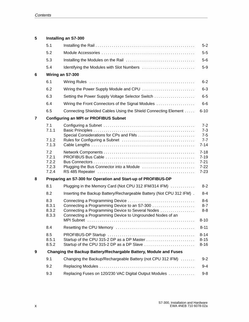
5 Installing an S7-300
5.1 Installing the Rail 5-2. . . . . . . . . . . . . . . . . . . . . . . . . . . . . . . . . . . . . . . . . . . . . . . . .
5.2 Module Accessories 5-5. . . . . . . . . . . . . . . . . . . . . . . . . . . . . . . . . . . . . . . . . . . . . .
5.3 Installing the Modules on the Rail 5-6. . . . . . . . . . . . . . . . . . . . . . . . . . . . . . . . . .
5.4 Identifying the Modules with Slot Numbers 5-9. . . . . . . . . . . . . . . . . . . . . . . . . .
6 Wiring an S7-300
6.1 Wiring Rules 6-2. . . . . . . . . . . . . . . . . . . . . . . . . . . . . . . . . . . . . . . . . . . . . . . . . . . .
6.2 Wiring the Power Supply Module and CPU 6-3. . . . . . . . . . . . . . . . . . . . . . . . . .
6.3 Setting the Power Supply Voltage Selector Switch 6-5. . . . . . . . . . . . . . . . . . . .
6.4 Wiring the Front Connectors of the Signal Modules 6-6. . . . . . . . . . . . . . . . . . .
6.5 Connecting Shielded Cables Using the Shield Connecting Element 6-10. . . . .
7 Configuring an MPI or PROFIBUS Subnet
7.1 Configuring a Subnet 7-2. . . . . . . . . . . . . . . . . . . . . . . . . . . . . . . . . . . . . . . . . . . . . 7.1.1 Basic Principles 7-3. . . . . . . . . . . . . . . . . . . . . . . . . . . . . . . . . . . . . . . . . . . . . . . . . .
Special Considerations for CPs and FMs 7-5. . . . . . . . . . . . . . . . . . . . . . . . . . . . 7.1.2 Rules for Configuring a Subnet 7-7. . . . . . . . . . . . . . . . . . . . . . . . . . . . . . . . . . . . 7.1.3 Cable Lengths 7-14. . . . . . . . . . . . . . . . . . . . . . . . . . . . . . . . . . . . . . . . . . . . . . . . . . .
7.2 Network Components 7-18. . . . . . . . . . . . . . . . . . . . . . . . . . . . . . . . . . . . . . . . . . . . . 7.2.1 PROFIBUS Bus Cable 7-19. . . . . . . . . . . . . . . . . . . . . . . . . . . . . . . . . . . . . . . . . . . . 7.2.2 Bus Connectors 7-21. . . . . . . . . . . . . . . . . . . . . . . . . . . . . . . . . . . . . . . . . . . . . . . . . . 7.2.3 Plugging the Bus Connector into a Module 7-22. . . . . . . . . . . . . . . . . . . . . . . . . . 7.2.4 RS 485 Repeater 7-23. . . . . . . . . . . . . . . . . . . . . . . . . . . . . . . . . . . . . . . . . . . . . . . .
8 Preparing an S7-300 for Operation and Start-up of PROFIBUS-DP
8.1 Plugging in the Memory Card (Not CPU 312 IFM/314 IFM) 8-2. . . . . . . . . . . .
8.2 Inserting the Backup Battery/Rechargeable Battery (Not CPU 312 IFM) 8-4.
8.3 Connecting a Programming Device 8-6. . . . . . . . . . . . . . . . . . . . . . . . . . . . . . . . . 8.3.1 Connecting a Programming Device to an S7-300 8-7. . . . . . . . . . . . . . . . . . . . . 8.3.2 Connecting a Programming Device to Several Nodes 8-8. . . . . . . . . . . . . . . . . 8.3.3 Connecting a Programming Device to Ungrounded Nodes of an
MPI Subnet 8-10. . . . . . . . . . . . . . . . . . . . . . . . . . . . . . . . . . . . . . . . . . . . . . . . . . . . .
8.4 Resetting the CPU Memory 8-11. . . . . . . . . . . . . . . . . . . . . . . . . . . . . . . . . . . . . . .
8.5 PROFIBUS-DP Startup 8-14. . . . . . . . . . . . . . . . . . . . . . . . . . . . . . . . . . . . . . . . . . . 8.5.1 Startup of the CPU 315-2 DP as a DP Master 8-15. . . . . . . . . . . . . . . . . . . . . . . . 8.5.2 Startup of the CPU 315-2 DP as a DP Slave 8-16. . . . . . . . . . . . . . . . . . . . . . . . .
9 Changing the Backup Battery/Rechargable Battery , Module and Fuses
9.1 Changing the Backup/Rechargeable Battery (not CPU 312 IFM) 9-2. . . . . . .
9.2 Replacing Modules 9-4. . . . . . . . . . . . . . . . . . . . . . . . . . . . . . . . . . . . . . . . . . . . . . .
9.3 Replacing Fuses on 120/230 VAC Digital Output Modules 9-8. . . . . . . . . . . . .
Contents
xiS7-300, Installation and HardwareEWA 4NEB 710 6078-02a
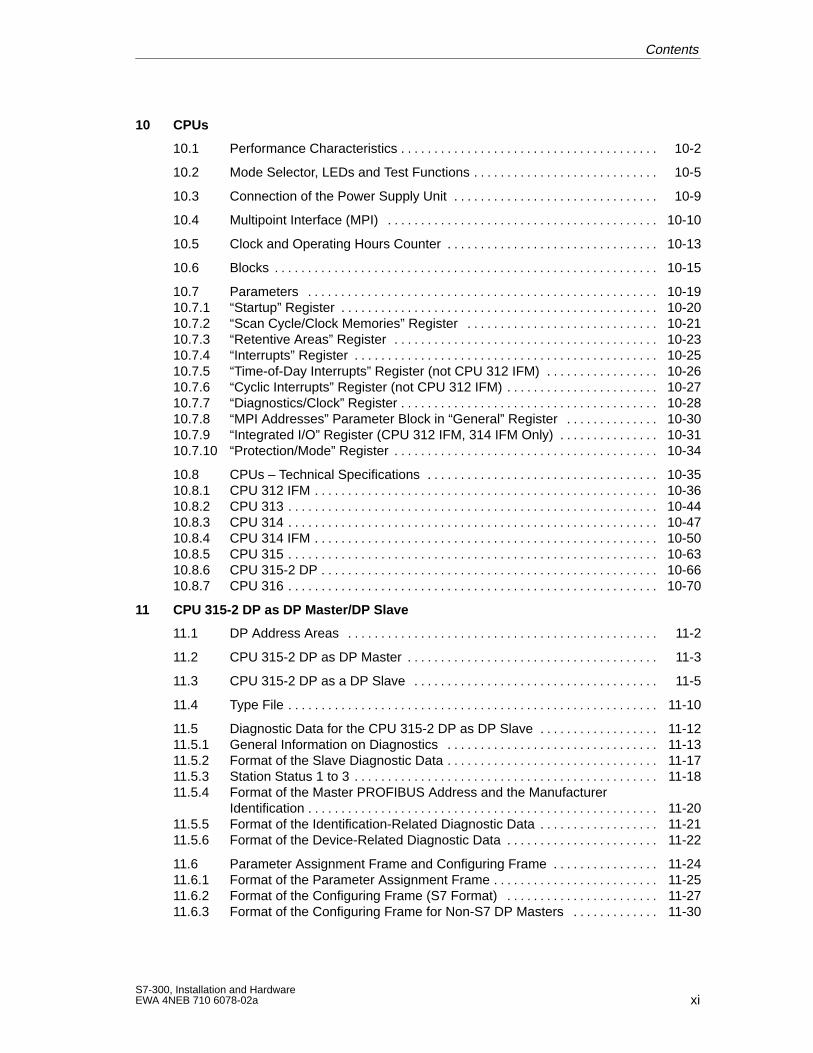
10 CPUs
10.1 Performance Characteristics 10-2. . . . . . . . . . . . . . . . . . . . . . . . . . . . . . . . . . . . . . .
10.2 Mode Selector, LEDs and Test Functions 10-5. . . . . . . . . . . . . . . . . . . . . . . . . . . .
10.3 Connection of the Power Supply Unit 10-9. . . . . . . . . . . . . . . . . . . . . . . . . . . . . . .
10.4 Multipoint Interface (MPI) 10-10. . . . . . . . . . . . . . . . . . . . . . . . . . . . . . . . . . . . . . . . .
10.5 Clock and Operating Hours Counter 10-13. . . . . . . . . . . . . . . . . . . . . . . . . . . . . . . .
10.6 Blocks 10-15. . . . . . . . . . . . . . . . . . . . . . . . . . . . . . . . . . . . . . . . . . . . . . . . . . . . . . . . . .
10.7 Parameters 10-19. . . . . . . . . . . . . . . . . . . . . . . . . . . . . . . . . . . . . . . . . . . . . . . . . . . . . 10.7.1 “Startup” Register 10-20. . . . . . . . . . . . . . . . . . . . . . . . . . . . . . . . . . . . . . . . . . . . . . . . 10.7.2 “Scan Cycle/Clock Memories” Register 10-21. . . . . . . . . . . . . . . . . . . . . . . . . . . . . 10.7.3 “Retentive Areas” Register 10-23. . . . . . . . . . . . . . . . . . . . . . . . . . . . . . . . . . . . . . . . 10.7.4 “Interrupts” Register 10-25. . . . . . . . . . . . . . . . . . . . . . . . . . . . . . . . . . . . . . . . . . . . . . 10.7.5 “Time-of-Day Interrupts” Register (not CPU 312 IFM) 10-26. . . . . . . . . . . . . . . . . 10.7.6 “Cyclic Interrupts” Register (not CPU 312 IFM) 10-27. . . . . . . . . . . . . . . . . . . . . . . 10.7.7 “Diagnostics/Clock” Register 10-28. . . . . . . . . . . . . . . . . . . . . . . . . . . . . . . . . . . . . . . 10.7.8 “MPI Addresses” Parameter Block in “General” Register 10-30. . . . . . . . . . . . . . 10.7.9 “Integrated I/O” Register (CPU 312 IFM, 314 IFM Only) 10-31. . . . . . . . . . . . . . . 10.7.10 “Protection/Mode” Register 10-34. . . . . . . . . . . . . . . . . . . . . . . . . . . . . . . . . . . . . . . .
10.8 CPUs – Technical Specifications 10-35. . . . . . . . . . . . . . . . . . . . . . . . . . . . . . . . . . . 10.8.1 CPU 312 IFM 10-36. . . . . . . . . . . . . . . . . . . . . . . . . . . . . . . . . . . . . . . . . . . . . . . . . . . . 10.8.2 CPU 313 10-44. . . . . . . . . . . . . . . . . . . . . . . . . . . . . . . . . . . . . . . . . . . . . . . . . . . . . . . . 10.8.3 CPU 314 10-47. . . . . . . . . . . . . . . . . . . . . . . . . . . . . . . . . . . . . . . . . . . . . . . . . . . . . . . . 10.8.4 CPU 314 IFM 10-50. . . . . . . . . . . . . . . . . . . . . . . . . . . . . . . . . . . . . . . . . . . . . . . . . . . . 10.8.5 CPU 315 10-63. . . . . . . . . . . . . . . . . . . . . . . . . . . . . . . . . . . . . . . . . . . . . . . . . . . . . . . . 10.8.6 CPU 315-2 DP 10-66. . . . . . . . . . . . . . . . . . . . . . . . . . . . . . . . . . . . . . . . . . . . . . . . . . . 10.8.7 CPU 316 10-70. . . . . . . . . . . . . . . . . . . . . . . . . . . . . . . . . . . . . . . . . . . . . . . . . . . . . . . .
11 CPU 315-2 DP as DP Master/DP Slave
11.1 DP Address Areas 11-2. . . . . . . . . . . . . . . . . . . . . . . . . . . . . . . . . . . . . . . . . . . . . . .
11.2 CPU 315-2 DP as DP Master 11-3. . . . . . . . . . . . . . . . . . . . . . . . . . . . . . . . . . . . . .
11.3 CPU 315-2 DP as a DP Slave 11-5. . . . . . . . . . . . . . . . . . . . . . . . . . . . . . . . . . . . .
11.4 Type File 11-10. . . . . . . . . . . . . . . . . . . . . . . . . . . . . . . . . . . . . . . . . . . . . . . . . . . . . . . .
11.5 Diagnostic Data for the CPU 315-2 DP as DP Slave 11-12. . . . . . . . . . . . . . . . . . 11.5.1 General Information on Diagnostics 11-13. . . . . . . . . . . . . . . . . . . . . . . . . . . . . . . . 11.5.2 Format of the Slave Diagnostic Data 11-17. . . . . . . . . . . . . . . . . . . . . . . . . . . . . . . . 11.5.3 Station Status 1 to 3 11-18. . . . . . . . . . . . . . . . . . . . . . . . . . . . . . . . . . . . . . . . . . . . . . 11.5.4 Format of the Master PROFIBUS Address and the Manufacturer
Identification 11-20. . . . . . . . . . . . . . . . . . . . . . . . . . . . . . . . . . . . . . . . . . . . . . . . . . . . . 11.5.5 Format of the Identification-Related Diagnostic Data 11-21. . . . . . . . . . . . . . . . . . 11.5.6 Format of the Device-Related Diagnostic Data 11-22. . . . . . . . . . . . . . . . . . . . . . .
11.6 Parameter Assignment Frame and Configuring Frame 11-24. . . . . . . . . . . . . . . . 11.6.1 Format of the Parameter Assignment Frame 11-25. . . . . . . . . . . . . . . . . . . . . . . . . 11.6.2 Format of the Configuring Frame (S7 Format) 11-27. . . . . . . . . . . . . . . . . . . . . . . 11.6.3 Format of the Configuring Frame for Non-S7 DP Masters 11-30. . . . . . . . . . . . .
Contents
xiiS7-300, Installation and Hardware
EWA 4NEB 710 6078-02a
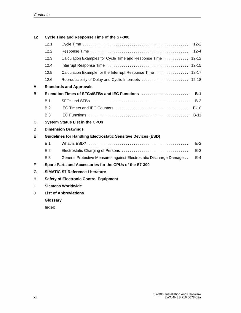
12 Cycle T ime and Response T ime of the S7-300
12.1 Cycle Time 12-2. . . . . . . . . . . . . . . . . . . . . . . . . . . . . . . . . . . . . . . . . . . . . . . . . . . . . .
12.2 Response Time 12-4. . . . . . . . . . . . . . . . . . . . . . . . . . . . . . . . . . . . . . . . . . . . . . . . . .
12.3 Calculation Examples for Cycle Time and Response Time 12-12. . . . . . . . . . . . .
12.4 Interrupt Response Time 12-15. . . . . . . . . . . . . . . . . . . . . . . . . . . . . . . . . . . . . . . . . .
12.5 Calculation Example for the Interrupt Response Time 12-17. . . . . . . . . . . . . . . . .
12.6 Reproducibility of Delay and Cyclic Interrupts 12-18. . . . . . . . . . . . . . . . . . . . . . . .
A Standards and Approvals
B Execution T imes of SFCs/SFBs and IEC Functions B-1. . . . . . . . . . . . . . . . . . . . . . . .
B.1 SFCs und SFBs B-2. . . . . . . . . . . . . . . . . . . . . . . . . . . . . . . . . . . . . . . . . . . . . . . . .
B.2 IEC Timers and IEC Counters B-10. . . . . . . . . . . . . . . . . . . . . . . . . . . . . . . . . . . . .
B.3 IEC Functions B-11. . . . . . . . . . . . . . . . . . . . . . . . . . . . . . . . . . . . . . . . . . . . . . . . . . .
C System Status List in the CPUs
D Dimension Drawings
E Guidelines for Handling Electrostatic Sensitive Devices (ESD)
E.1 What is ESD? E-2. . . . . . . . . . . . . . . . . . . . . . . . . . . . . . . . . . . . . . . . . . . . . . . . . . .
E.2 Electrostatic Charging of Persons E-3. . . . . . . . . . . . . . . . . . . . . . . . . . . . . . . . . .
E.3 General Protective Measures against Electrostatic Discharge Damage E-4. .
F Spare Parts and Accessories for the CPUs of the S7-300
G SIMATIC S7 Reference Literature
H Safety of Electronic Control Equipment
I Siemens W orldwide
J List of Abbreviations
Glossary
Index
Contents
xiiiS7-300, Installation and HardwareEWA 4NEB 710 6078-02a
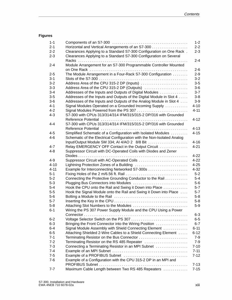
Figures
1-1 Components of an S7-300 1-2. . . . . . . . . . . . . . . . . . . . . . . . . . . . . . . . . . . . . . . . 2-1 Horizontal and Vertical Arrangements of an S7-300 2-2. . . . . . . . . . . . . . . . . . . 2-2 Clearances Applying to a Standard S7-300 Configuration on One Rack 2-3. 2-3 Clearances Applying to a Standard S7-300 Configuration on Several
Racks 2-4. . . . . . . . . . . . . . . . . . . . . . . . . . . . . . . . . . . . . . . . . . . . . . . . . . . . . . . . . . 2-4 Module Arrangement for an S7-300 Programmable Controller Mounted
on One Rack 2-6. . . . . . . . . . . . . . . . . . . . . . . . . . . . . . . . . . . . . . . . . . . . . . . . . . . . 2-5 The Module Arrangement in a Four-Rack S7-300 Configuration 2-9. . . . . . . . 3-1 Slots of the S7-300 3-2. . . . . . . . . . . . . . . . . . . . . . . . . . . . . . . . . . . . . . . . . . . . . . . 3-2 Address Area of the CPU 315-2 DP (Inputs) 3-5. . . . . . . . . . . . . . . . . . . . . . . . . 3-3 Address Area of the CPU 315-2 DP (Outputs) 3-6. . . . . . . . . . . . . . . . . . . . . . . 3-4 Addresses of the Inputs and Outputs of Digital Modules 3-7. . . . . . . . . . . . . . . 3-5 Addresses of the Inputs and Outputs of the Digital Module in Slot 4 3-8. . . . . 3-6 Addresses of the Inputs and Outputs of the Analog Module in Slot 4 3-9. . . . 4-1 Signal Modules Operated on a Grounded Incoming Supply 4-10. . . . . . . . . . . . 4-2 Signal Modules Powered from the PS 307 4-11. . . . . . . . . . . . . . . . . . . . . . . . . . . 4-3 S7-300 with CPUs 313/314/314 IFM/315/315-2 DP/316 with Grounded
Reference Potential 4-12. . . . . . . . . . . . . . . . . . . . . . . . . . . . . . . . . . . . . . . . . . . . . . 4-4 S7-300 with CPUs 313/314/314 IFM/315/315-2 DP/316 with Grounded
Reference Potential 4-13. . . . . . . . . . . . . . . . . . . . . . . . . . . . . . . . . . . . . . . . . . . . . . 4-5 Simplified Schematic of a Configuration with Isolated Modules 4-15. . . . . . . . . 4-6 Schematic of the Electrical Configuration with the Non-Isolated Analog
Input/Output Module SM 334; AI 4/AO 2 8/8 Bit 4-16. . . . . . . . . . . . . . . . . . . . . 4-7 Relay EMERGENCY OFF Contact in the Output Circuit 4-21. . . . . . . . . . . . . . . 4-8 Suppressor Circuit with DC-Operated Coils with Diodes and Zener
Diodes 4-22. . . . . . . . . . . . . . . . . . . . . . . . . . . . . . . . . . . . . . . . . . . . . . . . . . . . . . . . . . 4-9 Suppressor Circuit with AC-Operated Coils 4-22. . . . . . . . . . . . . . . . . . . . . . . . . . 4-10 Lightning Protection Zones of a Building 4-25. . . . . . . . . . . . . . . . . . . . . . . . . . . . 4-11 Example for Interconnecting Networked S7-300s 4-32. . . . . . . . . . . . . . . . . . . . . 5-1 Fixing Holes of the 2 m/6.56 ft. Rail 5-2. . . . . . . . . . . . . . . . . . . . . . . . . . . . . . . . . 5-2 Connecting the Protective Grounding Conductor to the Rail 5-4. . . . . . . . . . . . 5-3 Plugging Bus Connectors into Modules 5-6. . . . . . . . . . . . . . . . . . . . . . . . . . . . . 5-4 Hook the CPU onto the Rail and Swing it Down into Place 5-7. . . . . . . . . . . . . 5-5 Hook the Signal Module onto the Rail and Swing it Down into Place 5-7. . . . 5-6 Bolting a Module to the Rail 5-8. . . . . . . . . . . . . . . . . . . . . . . . . . . . . . . . . . . . . . . 5-7 Inserting the Key in the CPU 5-8. . . . . . . . . . . . . . . . . . . . . . . . . . . . . . . . . . . . . . . 5-8 Attaching Slot Numbers to the Modules 5-9. . . . . . . . . . . . . . . . . . . . . . . . . . . . . 6-1 Wiring the PS 307 Power Supply Module and the CPU Using a Power
Connector 6-3. . . . . . . . . . . . . . . . . . . . . . . . . . . . . . . . . . . . . . . . . . . . . . . . . . . . . . . 6-2 Voltage Selector Switch on the PS 307 6-5. . . . . . . . . . . . . . . . . . . . . . . . . . . . . . 6-3 Bringing the Front Connector into the Wiring Position 6-7. . . . . . . . . . . . . . . . . 6-4 Signal Module Assembly with Shield Connecting Element 6-11. . . . . . . . . . . . . 6-5 Attaching Shielded 2-Wire Cables to a Shield Connecting Element 6-12. . . . . 7-1 Terminating Resistor on the Bus Connector 7-9. . . . . . . . . . . . . . . . . . . . . . . . . . 7-2 Terminating Resistor on the RS 485 Repeater 7-9. . . . . . . . . . . . . . . . . . . . . . . 7-3 Connecting a Terminating Resistor in an MPI Subnet 7-10. . . . . . . . . . . . . . . . . 7-4 Example of an MPI Subnet 7-11. . . . . . . . . . . . . . . . . . . . . . . . . . . . . . . . . . . . . . . . 7-5 Example of a PROFIBUS Subnet 7-12. . . . . . . . . . . . . . . . . . . . . . . . . . . . . . . . . . 7-6 Example of a Configuration with the CPU 315-2 DP in an MPI and
PROFIBUS Subnet 7-13. . . . . . . . . . . . . . . . . . . . . . . . . . . . . . . . . . . . . . . . . . . . . . . 7-7 Maximum Cable Length between Two RS 485 Repeaters 7-15. . . . . . . . . . . . .
Contents
xivS7-300, Installation and Hardware
EWA 4NEB 710 6078-02a
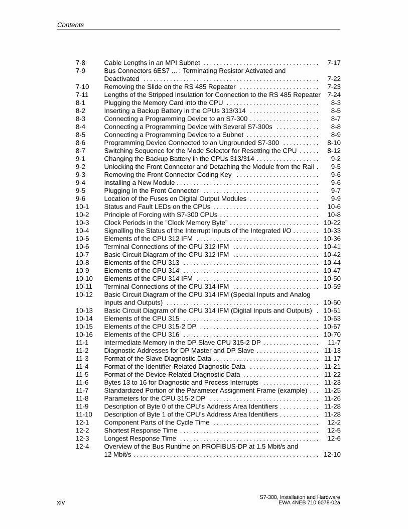
7-8 Cable Lengths in an MPI Subnet 7-17. . . . . . . . . . . . . . . . . . . . . . . . . . . . . . . . . . . 7-9 Bus Connectors 6ES7 ... : Terminating Resistor Activated and
Deactivated 7-22. . . . . . . . . . . . . . . . . . . . . . . . . . . . . . . . . . . . . . . . . . . . . . . . . . . . . 7-10 Removing the Slide on the RS 485 Repeater 7-23. . . . . . . . . . . . . . . . . . . . . . . . 7-11 Lengths of the Stripped Insulation for Connection to the RS 485 Repeater 7-248-1 Plugging the Memory Card into the CPU 8-3. . . . . . . . . . . . . . . . . . . . . . . . . . . . 8-2 Inserting a Backup Battery in the CPUs 313/314 8-5. . . . . . . . . . . . . . . . . . . . . 8-3 Connecting a Programming Device to an S7-300 8-7. . . . . . . . . . . . . . . . . . . . . 8-4 Connecting a Programming Device with Several S7-300s 8-8. . . . . . . . . . . . . 8-5 Connecting a Programming Device to a Subnet 8-9. . . . . . . . . . . . . . . . . . . . . . 8-6 Programming Device Connected to an Ungrounded S7-300 8-10. . . . . . . . . . . 8-7 Switching Sequence for the Mode Selector for Resetting the CPU 8-12. . . . . . 9-1 Changing the Backup Battery in the CPUs 313/314 9-2. . . . . . . . . . . . . . . . . . . 9-2 Unlocking the Front Connector and Detaching the Module from the Rail 9-5. 9-3 Removing the Front Connector Coding Key 9-6. . . . . . . . . . . . . . . . . . . . . . . . . 9-4 Installing a New Module 9-6. . . . . . . . . . . . . . . . . . . . . . . . . . . . . . . . . . . . . . . . . . . 9-5 Plugging In the Front Connector 9-7. . . . . . . . . . . . . . . . . . . . . . . . . . . . . . . . . . . 9-6 Location of the Fuses on Digital Output Modules 9-9. . . . . . . . . . . . . . . . . . . . . 10-1 Status and Fault LEDs on the CPUs 10-6. . . . . . . . . . . . . . . . . . . . . . . . . . . . . . . . 10-2 Principle of Forcing with S7-300 CPUs 10-8. . . . . . . . . . . . . . . . . . . . . . . . . . . . . . 10-3 Clock Periods in the ”Clock Memory Byte” 10-22. . . . . . . . . . . . . . . . . . . . . . . . . . . 10-4 Signalling the Status of the Interrupt Inputs of the Integrated I/O 10-33. . . . . . . . 10-5 Elements of the CPU 312 IFM 10-36. . . . . . . . . . . . . . . . . . . . . . . . . . . . . . . . . . . . . 10-6 Terminal Connections of the CPU 312 IFM 10-41. . . . . . . . . . . . . . . . . . . . . . . . . . 10-7 Basic Circuit Diagram of the CPU 312 IFM 10-42. . . . . . . . . . . . . . . . . . . . . . . . . . 10-8 Elements of the CPU 313 10-44. . . . . . . . . . . . . . . . . . . . . . . . . . . . . . . . . . . . . . . . . 10-9 Elements of the CPU 314 10-47. . . . . . . . . . . . . . . . . . . . . . . . . . . . . . . . . . . . . . . . . 10-10 Elements of the CPU 314 IFM 10-50. . . . . . . . . . . . . . . . . . . . . . . . . . . . . . . . . . . . . 10-11 Terminal Connections of the CPU 314 IFM 10-59. . . . . . . . . . . . . . . . . . . . . . . . . . 10-12 Basic Circuit Diagram of the CPU 314 IFM (Special Inputs and Analog
Inputs and Outputs) 10-60. . . . . . . . . . . . . . . . . . . . . . . . . . . . . . . . . . . . . . . . . . . . . . 10-13 Basic Circuit Diagram of the CPU 314 IFM (Digital Inputs and Outputs) 10-61. 10-14 Elements of the CPU 315 10-63. . . . . . . . . . . . . . . . . . . . . . . . . . . . . . . . . . . . . . . . . 10-15 Elements of the CPU 315-2 DP 10-67. . . . . . . . . . . . . . . . . . . . . . . . . . . . . . . . . . . . 10-16 Elements of the CPU 316 10-70. . . . . . . . . . . . . . . . . . . . . . . . . . . . . . . . . . . . . . . . . 11-1 Intermediate Memory in the DP Slave CPU 315-2 DP 11-7. . . . . . . . . . . . . . . . . 11-2 Diagnostic Addresses for DP Master and DP Slave 11-13. . . . . . . . . . . . . . . . . . . 11-3 Format of the Slave Diagnostic Data 11-17. . . . . . . . . . . . . . . . . . . . . . . . . . . . . . . . 11-4 Format of the Identifier-Related Diagnostic Data 11-21. . . . . . . . . . . . . . . . . . . . . 11-5 Format of the Device-Related Diagnostic Data 11-22. . . . . . . . . . . . . . . . . . . . . . . 11-6 Bytes 13 to 16 for Diagnostic and Process Interrupts 11-23. . . . . . . . . . . . . . . . . 11-7 Standardized Portion of the Parameter Assignment Frame (example) 11-25. . . 11-8 Parameters for the CPU 315-2 DP 11-26. . . . . . . . . . . . . . . . . . . . . . . . . . . . . . . . . 11-9 Description of Byte 0 of the CPU’s Address Area Identifiers 11-28. . . . . . . . . . . . 11-10 Description of Byte 1 of the CPU’s Address Area Identifiers 11-28. . . . . . . . . . . . 12-1 Component Parts of the Cycle Time 12-2. . . . . . . . . . . . . . . . . . . . . . . . . . . . . . . . 12-2 Shortest Response Time 12-5. . . . . . . . . . . . . . . . . . . . . . . . . . . . . . . . . . . . . . . . . . 12-3 Longest Response Time 12-6. . . . . . . . . . . . . . . . . . . . . . . . . . . . . . . . . . . . . . . . . . 12-4 Overview of the Bus Runtime on PROFIBUS-DP at 1.5 Mbit/s and
12 Mbit/s 12-10. . . . . . . . . . . . . . . . . . . . . . . . . . . . . . . . . . . . . . . . . . . . . . . . . . . . . . . .
Contents
xvS7-300, Installation and HardwareEWA 4NEB 710 6078-02a
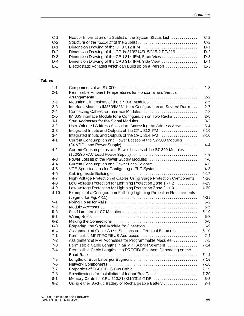
C-1 Header Information of a Sublist of the System Status List C-2. . . . . . . . . . . . . C-2 Structure of the “SZL-ID” of the Sublist C-2. . . . . . . . . . . . . . . . . . . . . . . . . . . . . . D-1 Dimension Drawing of the CPU 312 IFM D-1. . . . . . . . . . . . . . . . . . . . . . . . . . . . D-2 Dimension Drawing of the CPUs 313/314/315/315-2 DP/316 D-2. . . . . . . . . . D-3 Dimension Drawing of the CPU 314 IFM, Front View D-3. . . . . . . . . . . . . . . . . . D-4 Dimension Drawing of the CPU 314 IFM, Side View D-4. . . . . . . . . . . . . . . . . . E-1 Electrostatic Voltages which can Build up on a Person E-3. . . . . . . . . . . . . . . .
Tables
1-1 Components of an S7-300 1-3. . . . . . . . . . . . . . . . . . . . . . . . . . . . . . . . . . . . . . . . 2-1 Permissible Ambient Temperatures for Horizontal and Vertical
Arrangements 2-2. . . . . . . . . . . . . . . . . . . . . . . . . . . . . . . . . . . . . . . . . . . . . . . . . . . 2-2 Mounting Dimensions of the S7-300 Modules 2-5. . . . . . . . . . . . . . . . . . . . . . . . 2-3 Interface Modules IM360/IM361 for a Configuration on Several Racks 2-7. . 2-4 Connecting Cables for Interface Modules 2-8. . . . . . . . . . . . . . . . . . . . . . . . . . . 2-5 IM 365 Interface Module for a Configuration on Two Racks 2-8. . . . . . . . . . . . 3-1 Start Addresses for the Signal Modules 3-3. . . . . . . . . . . . . . . . . . . . . . . . . . . . 3-2 User-Oriented Address Allocation: Accessing the Address Areas 3-4. . . . . . 3-3 Integrated Inputs and Outputs of the CPU 312 IFM 3-10. . . . . . . . . . . . . . . . . . 3-4 Integrated Inputs and Outputs of the CPU 314 IFM 3-10. . . . . . . . . . . . . . . . . . 4-1 Current Consumption and Power Losses of the S7-300 Modules
(24 VDC Load Power Supply) 4-4. . . . . . . . . . . . . . . . . . . . . . . . . . . . . . . . . . . . . 4-2 Current Consumptions and Power Losses of the S7-300 Modules
(120/230 VAC Load Power Supply) 4-5. . . . . . . . . . . . . . . . . . . . . . . . . . . . . . . . . 4-3 Power Losses of the Power Supply Modules 4-6. . . . . . . . . . . . . . . . . . . . . . . . 4-4 Current Consumption and Power Loss Balance 4-6. . . . . . . . . . . . . . . . . . . . . 4-5 VDE Specifications for Configuring a PLC System 4-8. . . . . . . . . . . . . . . . . . . . 4-6 Cabling Inside Buildings 4-17. . . . . . . . . . . . . . . . . . . . . . . . . . . . . . . . . . . . . . . . . . 4-7 High-Voltage Protection of Cables Using Surge Protection Components 4-264-8 Low-Voltage Protection for Lightning Protection Zone 1 2 4-29. . . . . . . . . . 4-9 Low-Voltage Protection for Lightning Protection Zone 2 3 4-30. . . . . . . . . . . 4-10 Example of a Configuration Fulfilling Lightning Protection Requirements
(Legend for Fig. 4-11) 4-31. . . . . . . . . . . . . . . . . . . . . . . . . . . . . . . . . . . . . . . . . . . . . 5-1 Fixing Holes for Rails 5-3. . . . . . . . . . . . . . . . . . . . . . . . . . . . . . . . . . . . . . . . . . . . 5-2 Module Accessories 5-5. . . . . . . . . . . . . . . . . . . . . . . . . . . . . . . . . . . . . . . . . . . . . 5-3 Slot Numbers for S7 Modules 5-10. . . . . . . . . . . . . . . . . . . . . . . . . . . . . . . . . . . . . . 6-1 Wiring Rules 6-2. . . . . . . . . . . . . . . . . . . . . . . . . . . . . . . . . . . . . . . . . . . . . . . . . . . . 6-2 Making the Connections 6-8. . . . . . . . . . . . . . . . . . . . . . . . . . . . . . . . . . . . . . . . . . 6-3 Preparing the Signal Module for Operation 6-9. . . . . . . . . . . . . . . . . . . . . . . . . . 6-4 Assignment of Cable Cross-Sections and Terminal Elements 6-10. . . . . . . . . . 7-1 Permissible MPI/PROFIBUS Addresses 7-4. . . . . . . . . . . . . . . . . . . . . . . . . . . . 7-2 Assignment of MPI Addresses for Programmable Modules 7-5. . . . . . . . . . . . 7-3 Permissible Cable Lengths in an MPI Subnet Segment 7-14. . . . . . . . . . . . . . . 7-4 Permissible Cable Lengths in a PROFIBUS subnet Depending on the
Baud Rate 7-14. . . . . . . . . . . . . . . . . . . . . . . . . . . . . . . . . . . . . . . . . . . . . . . . . . . . . . 7-5 Lengths of Spur Lines per Segment 7-16. . . . . . . . . . . . . . . . . . . . . . . . . . . . . . . . 7-6 Network Components 7-18. . . . . . . . . . . . . . . . . . . . . . . . . . . . . . . . . . . . . . . . . . . . 7-7 Properties of PROFIBUS Bus Cable 7-19. . . . . . . . . . . . . . . . . . . . . . . . . . . . . . . . 7-8 Specifications for Installation of Indoor Bus Cable 7-20. . . . . . . . . . . . . . . . . . . . 8-1 Memory Cards for CPU 313/314/315/315-2 DP 8-2. . . . . . . . . . . . . . . . . . . . . . 8-2 Using either Backup Battery or Rechargeable Battery 8-4. . . . . . . . . . . . . . . . .
Contents
xviS7-300, Installation and Hardware
EWA 4NEB 710 6078-02a
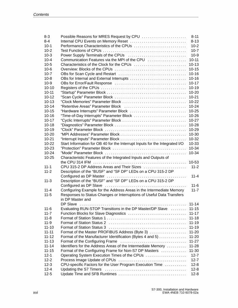
8-3 Possible Reasons for MRES Request by CPU 8-11. . . . . . . . . . . . . . . . . . . . . . . 8-4 Internal CPU Events on Memory Reset 8-13. . . . . . . . . . . . . . . . . . . . . . . . . . . . . 10-1 Performance Characteristics of the CPUs 10-2. . . . . . . . . . . . . . . . . . . . . . . . . . . 10-2 Test Functions of CPUs 10-7. . . . . . . . . . . . . . . . . . . . . . . . . . . . . . . . . . . . . . . . . . . 10-3 Power Supply Terminals of the CPUs 10-9. . . . . . . . . . . . . . . . . . . . . . . . . . . . . . 10-4 Communication Features via the MPI of the CPU 10-11. . . . . . . . . . . . . . . . . . . . 10-5 Characteristics of the Clock for the CPUs 10-13. . . . . . . . . . . . . . . . . . . . . . . . . . . 10-6 Overview: Blocks of the CPUs 10-15. . . . . . . . . . . . . . . . . . . . . . . . . . . . . . . . . . . . . 10-7 OBs for Scan Cycle and Restart 10-16. . . . . . . . . . . . . . . . . . . . . . . . . . . . . . . . . . . 10-8 OBs for Internal and External Interrupts 10-16. . . . . . . . . . . . . . . . . . . . . . . . . . . . . 10-9 OBs for Error/Fault Response 10-17. . . . . . . . . . . . . . . . . . . . . . . . . . . . . . . . . . . . . 10-10 Registers of the CPUs 10-19. . . . . . . . . . . . . . . . . . . . . . . . . . . . . . . . . . . . . . . . . . . . 10-11 “Startup” Parameter Block 10-20. . . . . . . . . . . . . . . . . . . . . . . . . . . . . . . . . . . . . . . . . 10-12 “Scan Cycle” Parameter Block 10-21. . . . . . . . . . . . . . . . . . . . . . . . . . . . . . . . . . . . . 10-13 “Clock Memories” Parameter Block 10-22. . . . . . . . . . . . . . . . . . . . . . . . . . . . . . . . . 10-14 “Retentive Areas” Parameter Block 10-24. . . . . . . . . . . . . . . . . . . . . . . . . . . . . . . . 10-15 “Hardware Interrupts” Parameter Block 10-25. . . . . . . . . . . . . . . . . . . . . . . . . . . . . 10-16 “Time-of-Day Interrupts” Parameter Block 10-26. . . . . . . . . . . . . . . . . . . . . . . . . . . 10-17 “Cyclic Interrupts” Parameter Block 10-27. . . . . . . . . . . . . . . . . . . . . . . . . . . . . . . . . 10-18 “Diagnostics” Parameter Block 10-28. . . . . . . . . . . . . . . . . . . . . . . . . . . . . . . . . . . . . 10-19 “Clock” Parameter Block 10-29. . . . . . . . . . . . . . . . . . . . . . . . . . . . . . . . . . . . . . . . . . 10-20 “MPI Addresses” Parameter Block 10-30. . . . . . . . . . . . . . . . . . . . . . . . . . . . . . . . . . 10-21 “Interrupt Inputs” Parameter Block 10-32. . . . . . . . . . . . . . . . . . . . . . . . . . . . . . . . . . 10-22 Start Information for OB 40 for the Interrupt Inputs for the Integrated I/O 10-3310-23 ”Protection” Parameter Block 10-34. . . . . . . . . . . . . . . . . . . . . . . . . . . . . . . . . . . . . . 10-24 ”Mode” Parameter Block 10-34. . . . . . . . . . . . . . . . . . . . . . . . . . . . . . . . . . . . . . . . . . 10-25 Characteristic Features of the Integrated Inputs and Outputs of
the CPU 314 IFM 10-53. . . . . . . . . . . . . . . . . . . . . . . . . . . . . . . . . . . . . . . . . . . . . . . . 11-1 CPU 315-2 DP Address Areas and Their Sizes 11-2. . . . . . . . . . . . . . . . . . . . . . 11-2 Description of the “BUSF” and “SF DP” LEDs on a CPU 315-2 DP
Configured as DP Master 11-4. . . . . . . . . . . . . . . . . . . . . . . . . . . . . . . . . . . . . . . . . 11-3 Description of the “BUSF” and “SF DP” LEDs on a CPU 315-2 DP
Configured as DP Slave 11-6. . . . . . . . . . . . . . . . . . . . . . . . . . . . . . . . . . . . . . . . . . 11-4 Configuring Example for the Address Areas in the Intermediate Memory 11-711-5 Responses to Status Changes or Interruptions of Useful Data Transfers
in DP Master andDP Slave 11-14. . . . . . . . . . . . . . . . . . . . . . . . . . . . . . . . . . . . . . . . . . . . . . . . . . . . . . .
11-6 Evaluating RUN-STOP Transitions in the DP Master/DP Slave 11-15. . . . . . . . 11-7 Function Blocks for Slave Diagnostics 11-17. . . . . . . . . . . . . . . . . . . . . . . . . . . . . . 11-8 Format of Station Status 1 11-18. . . . . . . . . . . . . . . . . . . . . . . . . . . . . . . . . . . . . . . . . 11-9 Format of Station Status 2 11-19. . . . . . . . . . . . . . . . . . . . . . . . . . . . . . . . . . . . . . . . 11-10 Format of Station Status 3 11-19. . . . . . . . . . . . . . . . . . . . . . . . . . . . . . . . . . . . . . . . 11-11 Format of the Master PROFIBUS Address (Byte 3) 11-20. . . . . . . . . . . . . . . . . . . 11-12 Format of the Manufacturer Identification (Bytes 4 and 5) 11-20. . . . . . . . . . . . . . 11-13 Format of the Configuring Frame 11-27. . . . . . . . . . . . . . . . . . . . . . . . . . . . . . . . . . 11-14 Identifiers for the Address Areas of the Intermediate Memory 11-28. . . . . . . . . . 11-15 Format of the Configuring Frame for Non-S7 DP Masters 11-30. . . . . . . . . . . . . 12-1 Operating System Execution Times of the CPUs 12-7. . . . . . . . . . . . . . . . . . . . . 12-2 Process Image Update of CPUs 12-7. . . . . . . . . . . . . . . . . . . . . . . . . . . . . . . . . . . 12-3 CPU-specific Factors for the User Program Execution Time 12-8. . . . . . . . . . . 12-4 Updating the S7 Timers 12-8. . . . . . . . . . . . . . . . . . . . . . . . . . . . . . . . . . . . . . . . . . 12-5 Update Time and SFB Runtimes 12-8. . . . . . . . . . . . . . . . . . . . . . . . . . . . . . . . . . .
Contents
xviiS7-300, Installation and HardwareEWA 4NEB 710 6078-02a
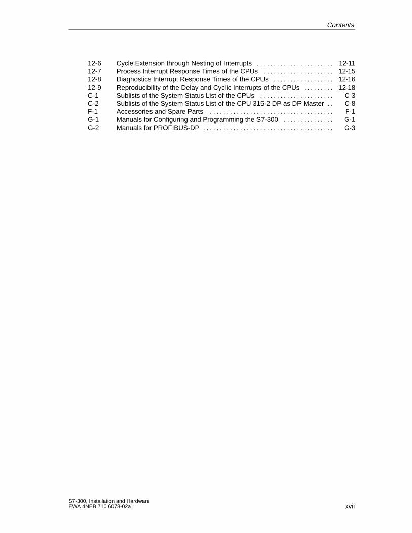
12-6 Cycle Extension through Nesting of Interrupts 12-11. . . . . . . . . . . . . . . . . . . . . . . 12-7 Process Interrupt Response Times of the CPUs 12-15. . . . . . . . . . . . . . . . . . . . . 12-8 Diagnostics Interrupt Response Times of the CPUs 12-16. . . . . . . . . . . . . . . . . . 12-9 Reproducibility of the Delay and Cyclic Interrupts of the CPUs 12-18. . . . . . . . . C-1 Sublists of the System Status List of the CPUs C-3. . . . . . . . . . . . . . . . . . . . . . C-2 Sublists of the System Status List of the CPU 315-2 DP as DP Master C-8. . F-1 Accessories and Spare Parts F-1. . . . . . . . . . . . . . . . . . . . . . . . . . . . . . . . . . . . . G-1 Manuals for Configuring and Programming the S7-300 G-1. . . . . . . . . . . . . . . G-2 Manuals for PROFIBUS-DP G-3. . . . . . . . . . . . . . . . . . . . . . . . . . . . . . . . . . . . . . .
Contents

xviiiS7-300, Installation and Hardware
EWA 4NEB 710 6078-02a
Contents
1-1S7-300, Installation and HardwareEWA 4NEB 710 6078-02a
Product Overview
The S7-300 has a modular design. You can set up your own individual systemby combining components from a comprehensive range of S7-300 modules.
The range of modules includes the following components:
CPUs for various performance ranges
Signal modules for digital and analog input/output(see Module Specifica-tions Reference Manual)
Function modules for technological functions (see the relevant functionmodule manual for a description).
CP communication processors (see the communication processor manualfor a description)
Load power supply modules for connecting the S7-300 to 120/230 VACpower supplies (see Module Specifications Reference Manual)
Interface modules for the interconnection of racks in multi-rack installa-tions (see Module Specifications Reference Manual)
All of the S7-300 modules are contained in housings protected to IP 20, i.e.they are encapsulated and can be operated without a fan.
In this chapter, we will introduce you to the most important components thatgo to make up an S7-300.
Modular Design
In this Chapter
1
1-2S7-300, Installation and Hardware
EWA 4NEB 710 6078-02a
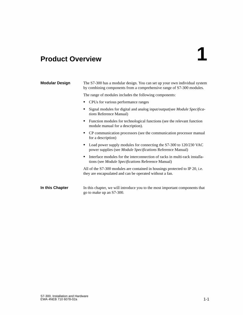
An S7-300 programmable controller is made up of the following compo-nents:
Power supply (PS)
CPU
Signal modules (SM)
Function modules (FM)
Communication processor (CP).
Several S7-300s can communicate with each other over PROFIBUS buscables.
You require a programming device to program the S7-300. You hook the pro-gramming device up to the S7-300 with a special programming device cable.
Fig. 1-1 shows a possible configuration with two S7-300 programmable con-trollers. The components in the shaded area are described in this manual.
Power supply (PS) Central processing unit CPU Signal module (SM) PROFIBUS bus cable Programming device cable
Figure 1-1 Components of an S7-300
Configuring anS7-300
Product Overview
1-3S7-300, Installation and HardwareEWA 4NEB 710 6078-02a
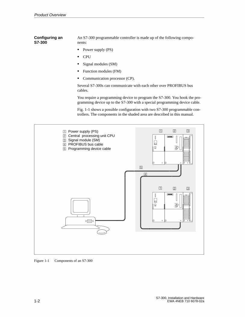
You have a number of components at your disposal for installing and startingup an S7-300 programmable controller. Table 1-1 lists the major componentsand their functions:
Table 1-1 Components of an S7-300
Components Function Illustration
Rail
Accessory:Shield connection element
... accommodates the S7-300modules
Power supply (PS) ... converts the power systemvoltage (120/230 VAC) into24 VDC for the S7-300 and loadpower supply for 24 VDC loadcircuits
CPU
Accessory:
CPU 313/314/315/315-2 DP/316
– Memory Card
– Backup battery (or accu-mulator for real-timeclock; except onCPU 313)
CPU 314 IFM
– Backup battery (or accu-mulator for real-timeclock)
– Front connector
CPU 312 IFM
– Front connector
... executes the user program;provides the 5 V supply for theS7-300 backplane bus; commu-nicates with other nodes in anMPI network via the MPI (mul-tipoint interface).You can also use the CPU 315-2DP in a PROFIBUS subnet:
as a DP master
as a DP slave on an S7/M7DP master or another DPmaster.
Signal modules (SMs)(digital input modules,digital output modules,digital input/output modulesanalog input moduleanalog output moduleanalog input/output modules)
Accessory:Front connector
... match different process signallevels to the S7-300
Components of anS7-300
Product Overview
1-4S7-300, Installation and Hardware
EWA 4NEB 710 6078-02a
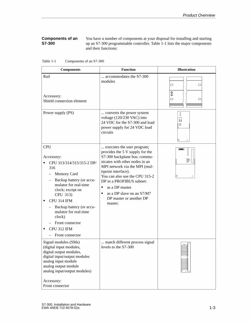
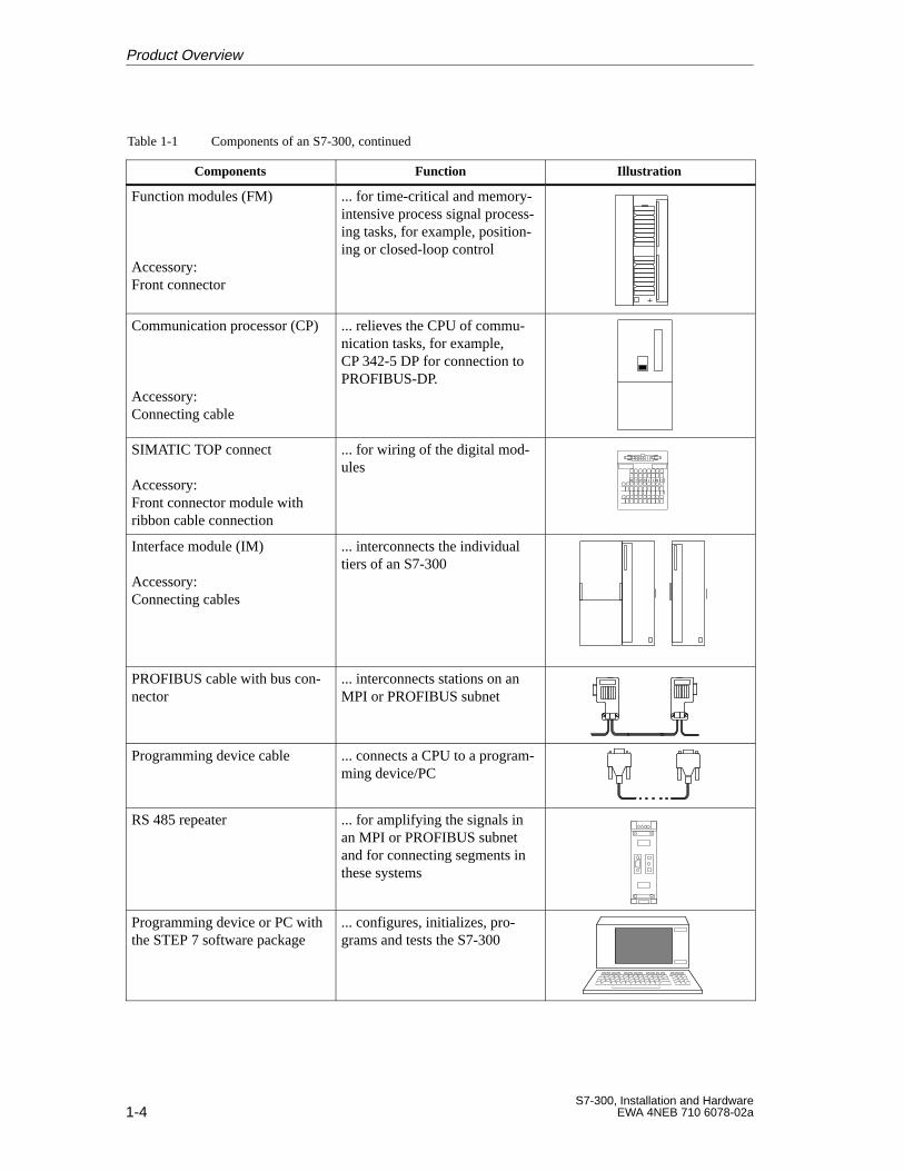
Table 1-1 Components of an S7-300, continued
Components IllustrationFunction
Function modules (FM)
Accessory:Front connector
... for time-critical and memory-intensive process signal process-ing tasks, for example, position-ing or closed-loop control
Communication processor (CP)
Accessory:Connecting cable
... relieves the CPU of commu-nication tasks, for example,CP 342-5 DP for connection toPROFIBUS-DP.
SIMATIC TOP connect
Accessory:Front connector module withribbon cable connection
... for wiring of the digital mod-ules
Interface module (IM)
Accessory:Connecting cables
... interconnects the individualtiers of an S7-300
PROFIBUS cable with bus con-nector
... interconnects stations on anMPI or PROFIBUS subnet
Programming device cable ... connects a CPU to a program-ming device/PC
RS 485 repeater ... for amplifying the signals inan MPI or PROFIBUS subnetand for connecting segments inthese systems
Programming device or PC withthe STEP 7 software package
... configures, initializes, pro-grams and tests the S7-300
Product Overview
2-1S7-300, Installation and HardwareEWA 4NEB 710 6078-02a
Mechanical Configuration
You will need to understand the following when installing an S7-300:
The mechanical configuration and
The electrical configuration.
Please therefore also read Chapter 4 “Electrical Configuration”.
The modules of an S7-300 are open components. That means you can onlyinstall the S7-300 in housings, cabinets or electrical equipment rooms whichare only accessible by key or a special tool. Only trained or authorized per-sonnel should have access to the housings, cabinets or electrical equipmentrooms.
This chapter contains the following sections on the mechanical configurationof the S7-300:
Section Contents Page
2.1 Horizontal and Vertical Arrangements of an S7-300 2-2
2.2 Mounting Dimensions of the S7-300 2-3
2.3 The Module Arrangement for an S7-300 Configura-tion on One Rack
2-6
2.4 The Module Arrangement for an S7-300 Configura-tion on Several Racks (not CPU 312 IFM/313)
2-7
Introduction
Open Components
In this Chapter
2
2-2S7-300, Installation and Hardware
EWA 4NEB 710 6078-02a
2.1 Horizontal and Vertical Arrangement of an S7-300
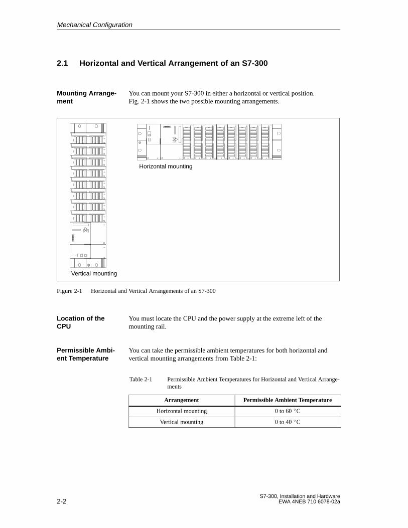
You can mount your S7-300 in either a horizontal or vertical position.Fig. 2-1 shows the two possible mounting arrangements.
Horizontal mounting
Vertical mounting
Figure 2-1 Horizontal and Vertical Arrangements of an S7-300
You must locate the CPU and the power supply at the extreme left of themounting rail.
You can take the permissible ambient temperatures for both horizontal andvertical mounting arrangements from Table 2-1:
Table 2-1 Permissible Ambient Temperatures for Horizontal and Vertical Arrange-ments
Arrangement Permissible Ambient Temperature
Horizontal mounting 0 to 60 C
Vertical mounting 0 to 40 C
Mounting Arrange -ment
Location of theCPU
Permissible Ambi -ent Temperature
Mechanical Configuration
2-3S7-300, Installation and HardwareEWA 4NEB 710 6078-02a
2.2 Mounting Dimensions of the S7-300
This section describes the various mounting dimensions for an S7-300 on oneor more racks.
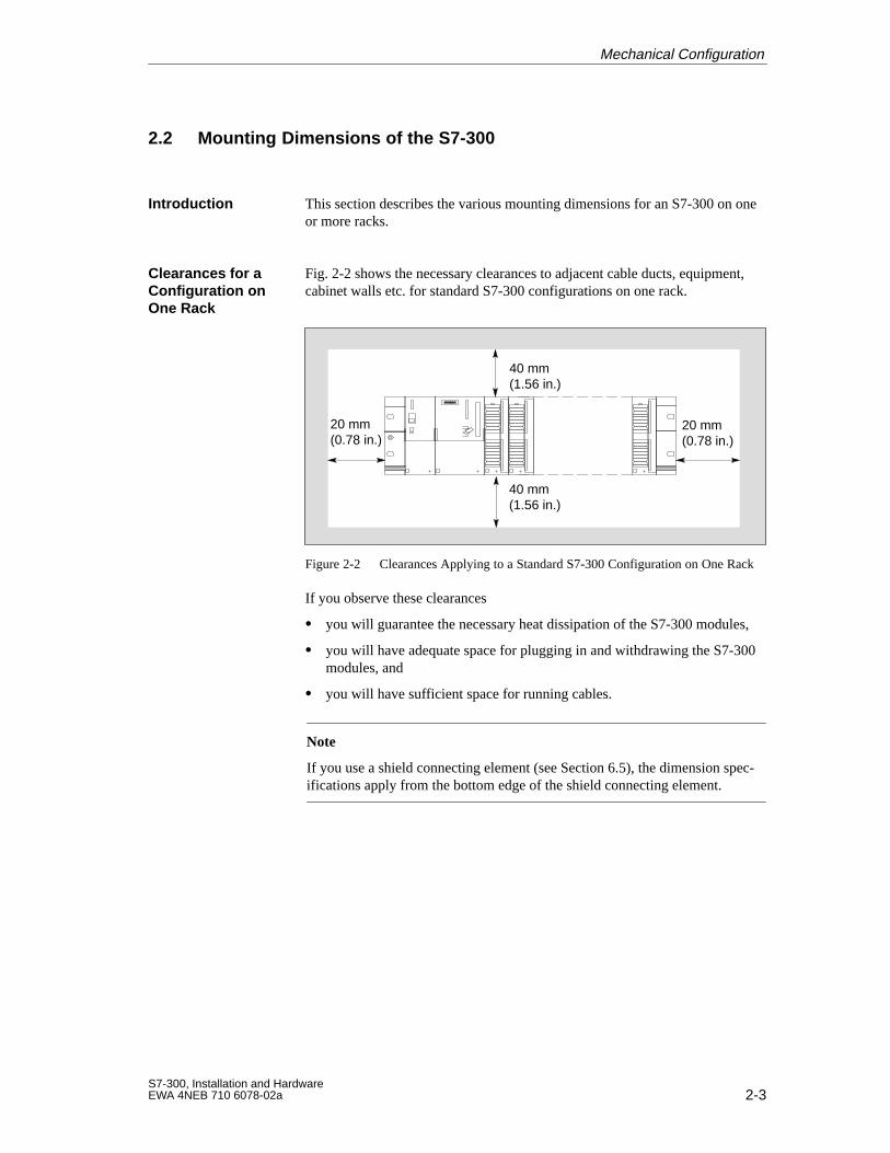
Fig. 2-2 shows the necessary clearances to adjacent cable ducts, equipment,cabinet walls etc. for standard S7-300 configurations on one rack.
40 mm(1.56 in.)
40 mm(1.56 in.)
20 mm(0.78 in.)
20 mm(0.78 in.)
Figure 2-2 Clearances Applying to a Standard S7-300 Configuration on One Rack
If you observe these clearances
you will guarantee the necessary heat dissipation of the S7-300 modules,
you will have adequate space for plugging in and withdrawing the S7-300modules, and
you will have sufficient space for running cables.
Note
If you use a shield connecting element (see Section 6.5), the dimension spec-ifications apply from the bottom edge of the shield connecting element.
Introduction
Clearances for aConfiguration onOne Rack
Mechanical Configuration
2-4S7-300, Installation and Hardware
EWA 4NEB 710 6078-02a
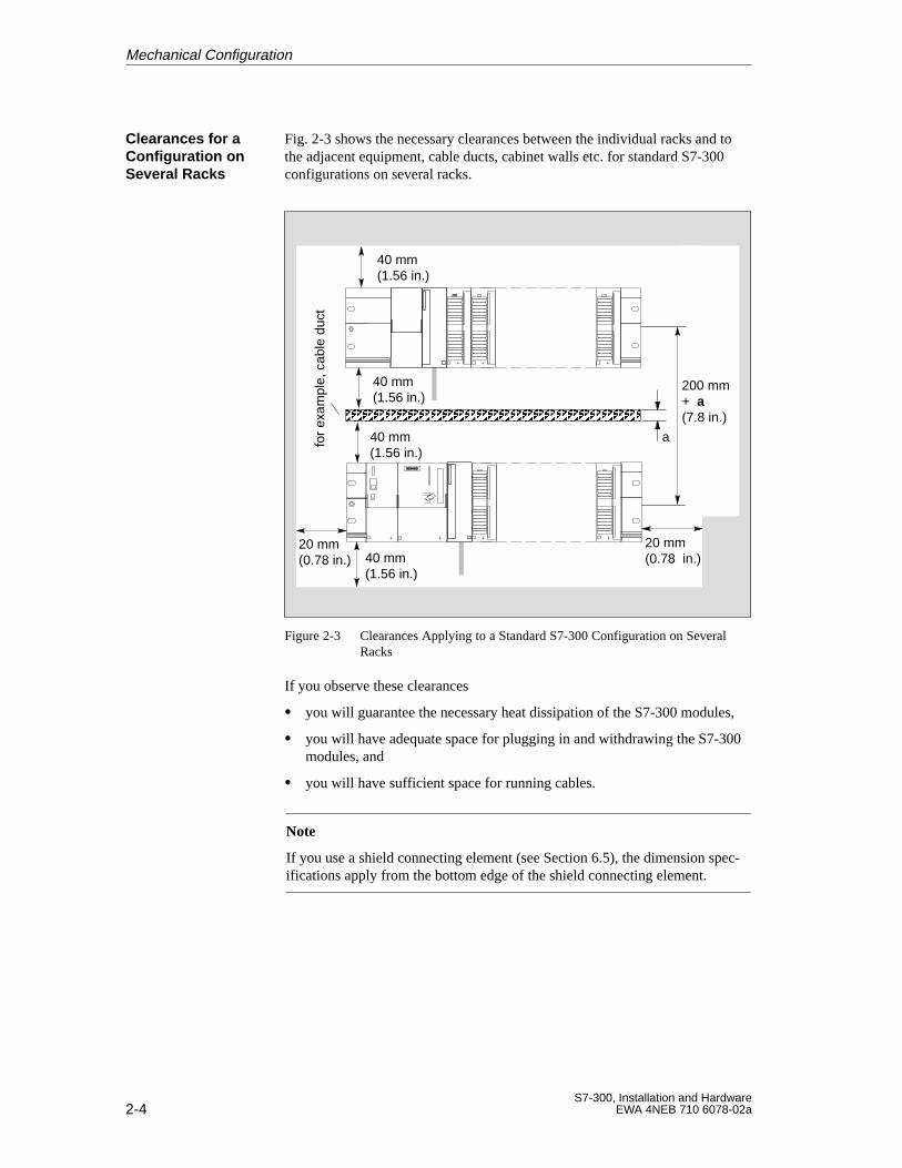
Fig. 2-3 shows the necessary clearances between the individual racks and tothe adjacent equipment, cable ducts, cabinet walls etc. for standard S7-300configurations on several racks.
40 mm (1.56 in.)
40 mm(1.56 in.)
20 mm(0.78 in.)
20 mm(0.78 in.)
ÂÂÂÂÂÂÂÂÂÂÂÂÂÂ
40 mm(1.56 in.)
40 mm(1.56 in.)
a
200 mm+ a(7.8 in.)
for
exam
ple,
cab
le d
uct
Figure 2-3 Clearances Applying to a Standard S7-300 Configuration on SeveralRacks
If you observe these clearances
you will guarantee the necessary heat dissipation of the S7-300 modules,
you will have adequate space for plugging in and withdrawing the S7-300modules, and
you will have sufficient space for running cables.
Note
If you use a shield connecting element (see Section 6.5), the dimension spec-ifications apply from the bottom edge of the shield connecting element.
Clearances for aConfiguration onSeveral Racks
Mechanical Configuration
2-5S7-300, Installation and HardwareEWA 4NEB 710 6078-02a
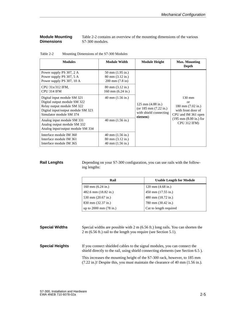
Table 2-2 contains an overview of the mounting dimensions of the variousS7-300 modules.
Table 2-2 Mounting Dimensions of the S7-300 Modules
Modules Module Width Module Height Max. MountingDepth
Power supply PS 307, 2 APower supply PS 307, 5 APower supply PS 307, 10 A
50 mm (1.95 in.)80 mm (3.12 in.)200 mm (7.8 in)
CPU 31x/312 IFM,CPU 314 IFM
80 mm (3.12 in.)160 mm (6.24 in.)
Digital input module SM 321Digital output module SM 322Relay output module SM 322Digital input/output module SM 323Simulator module SM 374
40 mm (1.56 in.)
125 mm (4.88 in.)(or 185 mm (7.22 in.)with shield connectingelement)
130 mmor
180 mm (7.02 in.)with front door of
CPU and IM 361 open(195 mm (8 00 in ) forAnalog input module SM 331
Analog output module SM 332Analog input/output module SM 334
40 mm (1.56 in.)element)
p(195 mm (8.00 in.) for
CPU 312 IFM)
Interface module IM 360Interface module IM 361Interface module IM 365
40 mm (1.56 in.)80 mm (3.12 in.)40 mm (1.56 in.)
Depending on your S7-300 configuration, you can use rails with the follow-ing lengths:
Rail Usable Length for Module
160 mm (6.24 in.)
482.6 mm (18.82 in.)
530 mm (20.67 in.)
830 mm (32.37 in.)
up to 2000 mm (78 in.)
120 mm (4.68 in.)
450 mm (17.55 in.)
480 mm (18.72 in.)
780 mm (30.42 in.)
Cut to length required
Special widths are possible with 2 m (6.56 ft.) long rails. You can shorten the2 m (6.56 ft.) rail to the length you require (see Section 5.1).
If you connect shielded cables to the signal modules, you can connect theshield directly to the rail, using shield connecting elements (see Section 6.5 ).
This increases the mounting height of the S7-300 rack, however, to 185 mm(7.22 in.)! Despite this, you must maintain the clearance of 40 mm (1.56 in.).
Module MountingDimensions
Rail Lenghts
Special W idths
Special Heights
Mechanical Configuration
2-6S7-300, Installation and Hardware
EWA 4NEB 710 6078-02a
2.3 The Module Arrangement for an S7-300 Configuration on One Rack
The following sections explain the rules governing the arrangement of themodules for an S7-300 programmable controller mounted on one rack.
The following rules apply to the arrangement of the modules on one rack:
No more than eight modules (SM, FM, CP) may be mounted to the rightof the CPU.
The number of modules (SM, FM, CP) that can be plugged in is limitedby the amount of power they draw from the S7-300’s backplane bus (seeTables 4-1 or 4-2 and the technical specifications of the individual mod-ules).
The total power drawn from the S7-300 backplane bus by all the moduleson one rack must not exceed
– for the CPUs 313/314/314 IFM/315/315-2 DP/3161.2 A
– for the CPU 312 IFM 0.8 A
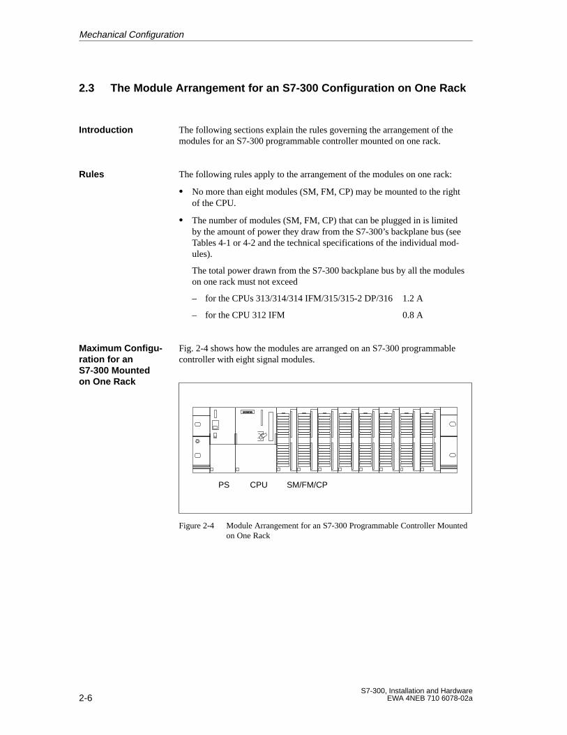
Fig. 2-4 shows how the modules are arranged on an S7-300 programmablecontroller with eight signal modules.
PS CPU SM/FM/CP
Figure 2-4 Module Arrangement for an S7-300 Programmable Controller Mountedon One Rack
Introduction
Rules
Maximum Configu-ration for anS7-300 Mountedon One Rack
Mechanical Configuration
2-7S7-300, Installation and HardwareEWA 4NEB 710 6078-02a
2.4 The Module Arrangement for an S7-300 Configuration on SeveralRacks (not CPU 312 IFM/313)
The following sections explain the rules governing the arrangement of themodules in an S7-300 configuration consisting of several racks.
Note
The CPU 312 IFM and CPU 313 can only be used for a configuration on onerack.
The following rules apply to the arrangement of the modules:
The interface module is always located in slot 3, to the left of the firstsignal module.
No more than 8 modules (SM, FM, CP) are permitted per rack. The mod-ules (SM, FM, CP) are always located to the right of the interface mod-ules.Exception: In the case of the CPU 314 IFM, a module must not beplugged into slot 11 on rack 3 (see Chapter 3)!
The number of modules (SM, FM, CP) that can be plugged in is limitedby the permissible current drawn from the S7-300 backplane bus. Thetotal current consumption per tier or rack must not exceed 1.2 A (seeTables 4-1 or 4-2 and the technical specifications of the modules).
If you mount the S7-300 on several racks, you require interface modules. Thetask of the interface modules is to connect the S7-300 backplane bus fromone rack to the next. The CPU is always in rack 0.
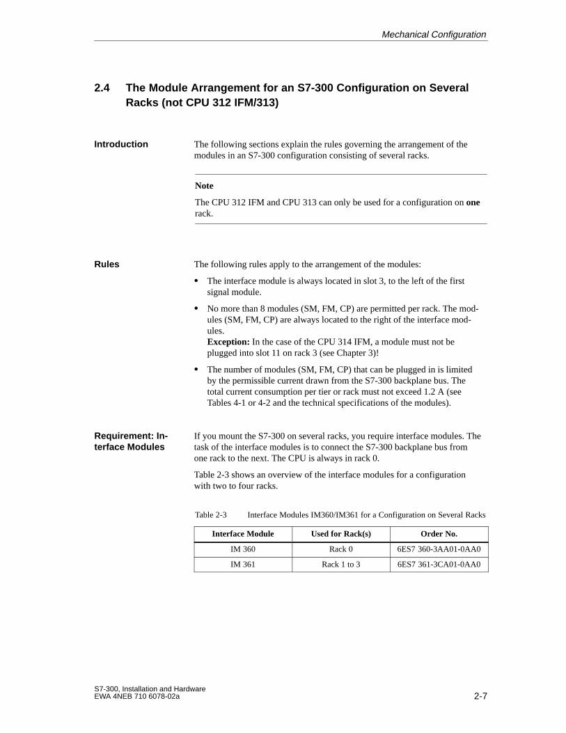
Table 2-3 shows an overview of the interface modules for a configurationwith two to four racks.
Table 2-3 Interface Modules IM360/IM361 for a Configuration on Several Racks
Interface Module Used for Rack(s) Order No.
IM 360 Rack 0 6ES7 360-3AA01-0AA0
IM 361 Rack 1 to 3 6ES7 361-3CA01-0AA0
Introduction
Rules
Requirement: In-terface Modules
Mechanical Configuration
2-8S7-300, Installation and Hardware
EWA 4NEB 710 6078-02a
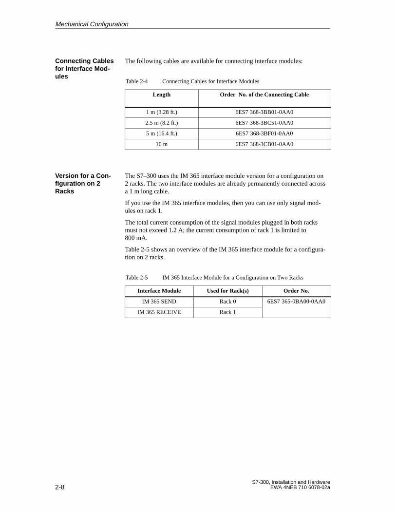
The following cables are available for connecting interface modules:
Table 2-4 Connecting Cables for Interface Modules
Length Order No. of the Connecting Cable
1 m (3.28 ft.) 6ES7 368-3BB01-0AA0
2.5 m (8.2 ft.) 6ES7 368-3BC51-0AA0
5 m (16.4 ft.) 6ES7 368-3BF01-0AA0
10 m 6ES7 368-3CB01-0AA0
The S7–300 uses the IM 365 interface module version for a configuration on2 racks. The two interface modules are already permanently connected acrossa 1 m long cable.
If you use the IM 365 interface modules, then you can use only signal mod-ules on rack 1.
The total current consumption of the signal modules plugged in both racksmust not exceed 1.2 A; the current consumption of rack 1 is limited to800 mA.
Table 2-5 shows an overview of the IM 365 interface module for a configura-tion on 2 racks.
Table 2-5 IM 365 Interface Module for a Configuration on Two Racks
Interface Module Used for Rack(s) Order No.
IM 365 SEND Rack 0 6ES7 365-0BA00-0AA0
IM 365 RECEIVE Rack 1
Connecting Cablesfor Interface Mod-ules
Version for a Con -figuration on 2Racks
Mechanical Configuration
2-9S7-300, Installation and HardwareEWA 4NEB 710 6078-02a
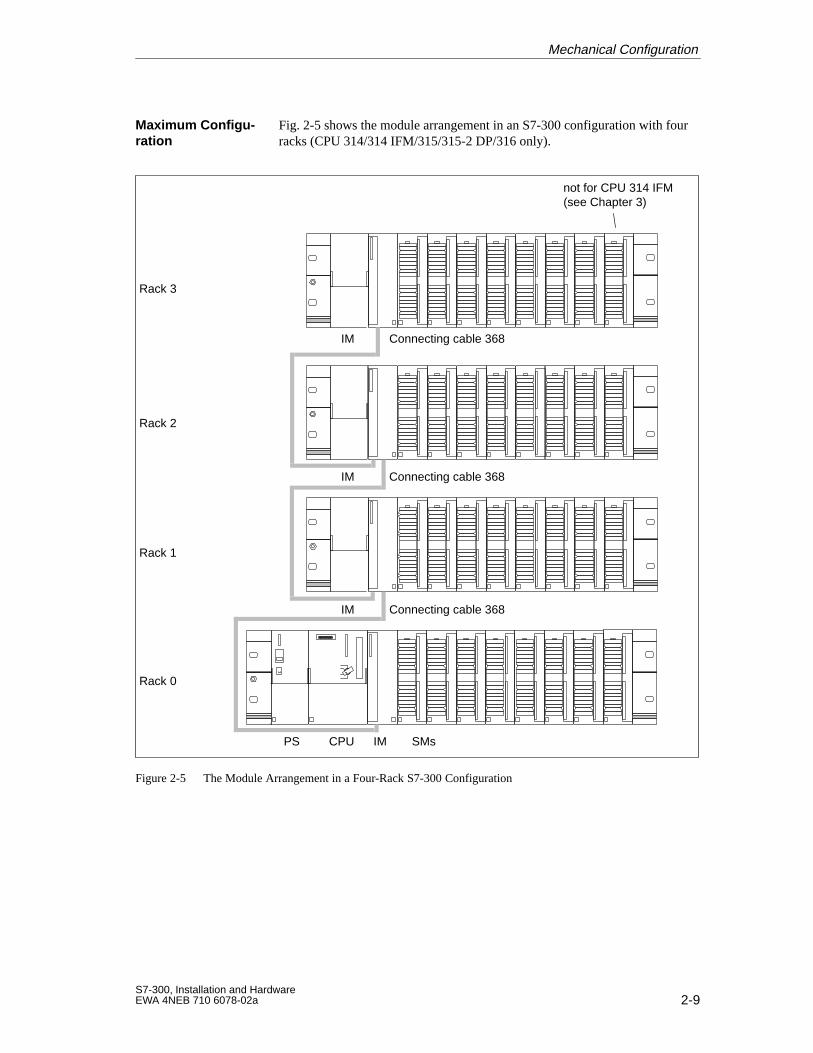
Fig. 2-5 shows the module arrangement in an S7-300 configuration with fourracks (CPU 314/314 IFM/315/315-2 DP/316 only).
PS CPU SMsIM
Connecting cable 368
Connecting cable 368
Connecting cable 368
Rack 0
Rack 1
Rack 2
Rack 3
IM
IM
IM
not for CPU 314 IFM(see Chapter 3)
Figure 2-5 The Module Arrangement in a Four-Rack S7-300 Configuration
Maximum Configu-ration
Mechanical Configuration

2-10S7-300, Installation and Hardware
EWA 4NEB 710 6078-02a
Mechanical Configuration
3-1S7-300, Installation and HardwareEWA 4NEB 710 6078-02a
Addressing the S7-300 Modules
In this chapter, you will learn about the different ways of addressing the indi-vidual channels of the signal modules.
Slot-oriented address allocation is the default addressing method on the S7,i.e. a defined module start address is allocated to each slot number.
With user-oriented address allocation, you can allocate any address within theavailable CPU address area to any module. User-oriented address allocationon the S7-300 is only possible with the CPU 315-2 DP.
You will find further information on addressing in the STEP 7 documenta-tion.
This chapter describes the addressing of the S7-300:
Section Contents Page
3.1 Slot-Oriented Addressing for Modules (Default Ad-dresses)
3-2
3.2 User-Oriented Addressing with the CPU 315-2 DP 3-4
3.3 Addressing Signal Modules 3-7
3.4 Addressing the Integrated Inputs and Outputs of theCPU 312 IFM und CPU 314 IFM
3-10
Introduction
Slot-Oriented Ad-dress Allocation
User-Oriented Ad -dress Allocation
Further Informa -tion
In this Chapter
3
3-2S7-300, Installation and Hardware
EWA 4NEB 710 6078-02a
3.1 Slot-Oriented Addressing for Modules (Default Addressing)
In slot-oriented addressing (default addressing), a module start address is al-located to each slot number (see Table 3-1). This section shows you whichmodule start address is allocated to which slot number. You need this infor-mation to determine the module start addresses on the installed modules.
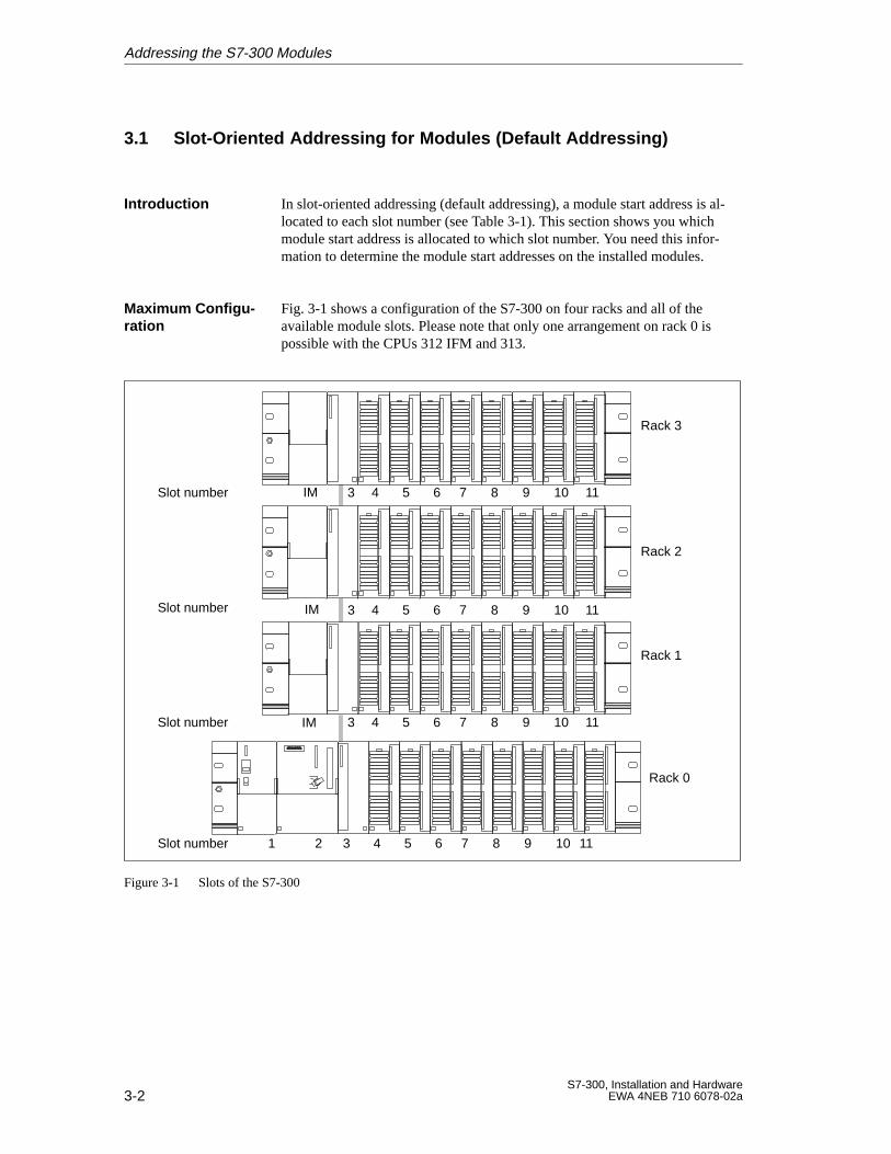
Fig. 3-1 shows a configuration of the S7-300 on four racks and all of theavailable module slots. Please note that only one arrangement on rack 0 ispossible with the CPUs 312 IFM and 313.
IM
1 2 3 4 5 6 7 8 9 10 11
Rack 3
3 4 5 6 7 8 9 10 11
3 4 5 6 7 8 9 10 11
Slot number 3 4 5 6 7 8 9 10 11
Slot number
Slot number
Slot number
Rack 2
Rack 1
Rack 0
IM
IM
Figure 3-1 Slots of the S7-300
Introduction
Maximum Configu-ration
Addressing the S7-300 Modules
3-3S7-300, Installation and HardwareEWA 4NEB 710 6078-02a
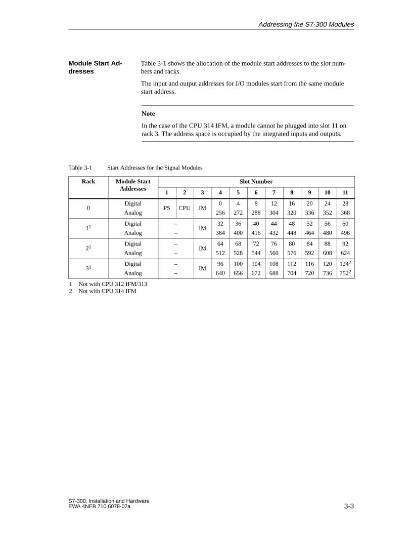
Table 3-1 shows the allocation of the module start addresses to the slot num-bers and racks.
The input and output addresses for I/O modules start from the same modulestart address.
Note
In the case of the CPU 314 IFM, a module cannot be plugged into slot 11 onrack 3. The address space is occupied by the integrated inputs and outputs.
Table 3-1 Start Addresses for the Signal Modules
Rack Module StartAddresses
Slot NumberAddresses
1 2 3 4 5 6 7 8 9 10 11
0Digital
AnalogPS CPU IM
0
256
4
272
8
288
12
304
16
320
20
336
24
352
28
368
11 Digital
Analog
–
–IM
32
384
36
400
40
416
44
432
48
448
52
464
56
480
60
496
21 Digital
Analog
–
–IM
64
512
68
528
72
544
76
560
80
576
84
592
88
608
92
624
31 Digital
Analog
–
–IM
96
640
100
656
104
672
108
688
112
704
116
720
120
736
1242
7522
1 Not with CPU 312 IFM/3132 Not with CPU 314 IFM
Module Start Ad -dresses
Addressing the S7-300 Modules
3-4S7-300, Installation and Hardware
EWA 4NEB 710 6078-02a
3.2 User-Oriented Address Allocation with the CPU 315-2 DP
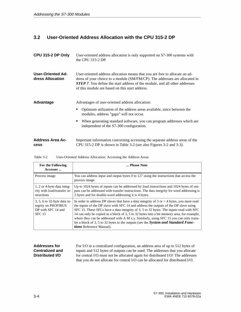
User-oriented address allocation is only supported on S7-300 systems withthe CPU 315-2 DP.
User-oriented address allocation means that you are free to allocate an ad-dress of your choice to a module (SM/FM/CP). The addresses are allocated inSTEP 7. You define the start address of the module, and all other addressesof this module are based on this start address.
Advantages of user-oriented address allocation:
Optimum utilization of the address areas available, since between themodules, address ”gaps” will not occur.
When generating standard software, you can program addresses which areindependent of the S7-300 configuration.
Important information concerning accessing the separate address areas of theCPU 315-2 DP is shown in Table 3-2 (see also Figures 3-2 and 3-3).
Table 3-2 User-Oriented Address Allocation: Accessing the Address Areas
For the FollowingAccesses ...
... Please Note
Process image You can address input and output bytes 0 to 127 using the instructions that access theprocess image.
1, 2 or 4-byte data integ-rity with load/transfer in-structions
Up to 1024 bytes of inputs can be addressed by load instructions and 1024 bytes of out-puts can be addressed with transfer instructions. The data integrity for word addressing is2 bytes and for double-word addressing it is 4 bytes.
3, 5, 6 to 32-byte data in-tegrity on PROFIBUSDP with SFC 14 andSFC 15
In order to address DP slaves that have a data integrity of 3 or > 4 bytes, you must readthe inputs of the DP slave with SFC 14 and address the outputs of the DP slave usingSFC 15. These SFCs have a data integrity of 3, 5 to 32 bytes. The inputs read with SFC14 can only be copied as a block of 3, 5 to 32 bytes into a bit memory area, for example,where they can be addressed with A M x.y. Similarly, using SFC 15 you can only trans-fer a block of 3, 5 to 32 bytes to the outputs (see the System and Standard Func-tions Reference Manual).
For I/O in a centralized configuration, an address area of up to 512 bytes ofinputs and 512 bytes of outputs can be used. The addresses that you allocatefor central I/O must not be allocated again for distributed I/O! The addressesthat you do not allocate for central I/O can be allocated for distributed I/O.
CPU 315-2 DP Only
User-Oriented Ad -dress Allocation
Advantage
Address Area Ac -cess
Addresses forCentralized andDistributed I/O
Addressing the S7-300 Modules
3-5S7-300, Installation and HardwareEWA 4NEB 710 6078-02a
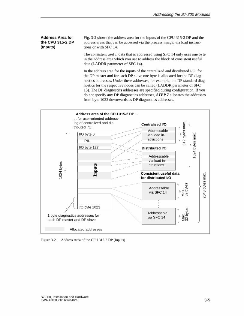
Fig. 3-2 shows the address area for the inputs of the CPU 315-2 DP and theaddress areas that can be accessed via the process image, via load instruc-tions or with SFC 14.
The consistent useful data that is addressed using SFC 14 only uses one bytein the address area which you use to address the block of consistent usefuldata (LADDR parameter of SFC 14).
In the address area for the inputs of the centralized and distributed I/O, forthe DP master and for each DP slave one byte is allocated for the DP diag-nostics addresses. Under these addresses, for example, the DP standard diag-nostics for the respective nodes can be called (LADDR parameter of SFC13). The DP diagnostics addresses are specified during configuration. If youdo not specify any DP diagnostics addresses, STEP 7 allocates the addressesfrom byte 1023 downwards as DP diagnostics addresses.
Address area of the CPU 315-2 DP ...... for user-oriented address-ing of centralized and dis-tributed I/O:
1 byte diagnostics addresses foreach DP master and DP slave
Allocated addresses
I/O byte 1023
Centralized I/O
Distributed I/O
Addressablevia SFC 14
Addressablevia SFC 14
1024
byt
es m
ax.
Max
.32
byt
esM
ax.
32 b
ytes
2048
byt
es m
ax.Consistent useful data
for distributed I/O1024
byt
es
512
byte
s m
ax.
I/O byte 0
PII.
Addressablevia load in-structions
Inpu
ts
Addressablevia load in-structions
I/O byte 127
Figure 3-2 Address Area of the CPU 315-2 DP (Inputs)
Address Area forthe CPU 315-2 DP(Inputs)
Addressing the S7-300 Modules
3-6S7-300, Installation and Hardware
EWA 4NEB 710 6078-02a
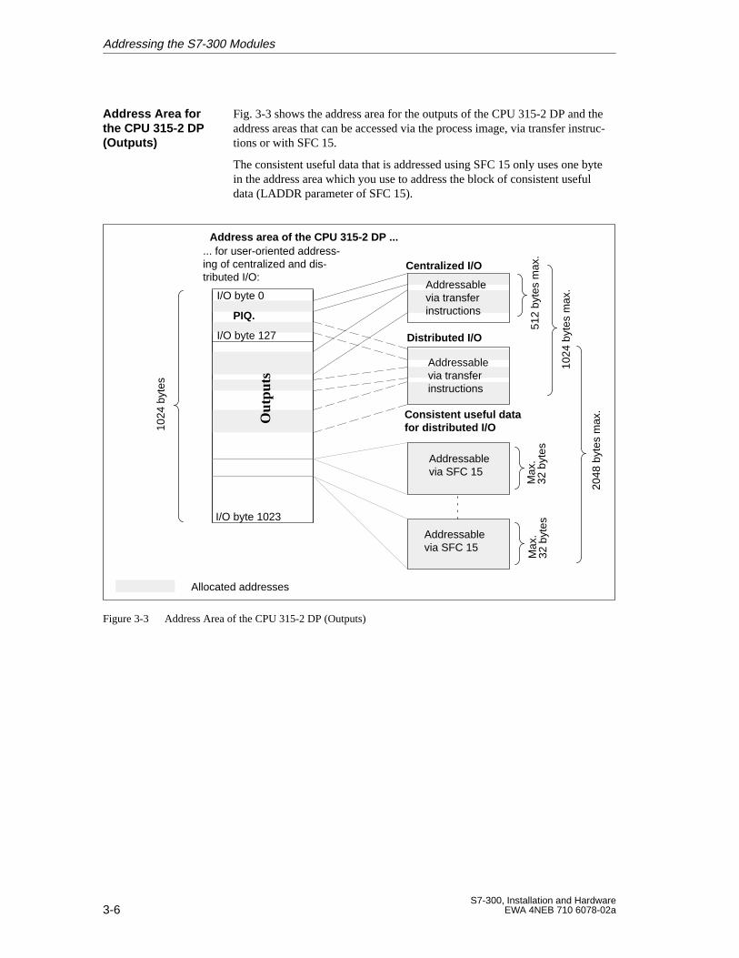
Fig. 3-3 shows the address area for the outputs of the CPU 315-2 DP and theaddress areas that can be accessed via the process image, via transfer instruc-tions or with SFC 15.
The consistent useful data that is addressed using SFC 15 only uses one bytein the address area which you use to address the block of consistent usefuldata (LADDR parameter of SFC 15).
Address area of the CPU 315-2 DP ...
I/O byte 1023
... for user-oriented address-ing of centralized and dis-tributed I/O:
Centralized I/O
Distributed I/O
Addressablevia SFC 15
Addressablevia SFC 15
1024
byt
es m
ax.
Max
.32
byt
esM
ax.
32 b
ytes
2048
byt
es m
ax.Consistent useful data
for distributed I/O1024
byt
es
512
byte
s m
ax.
I/O byte 0
PIQ.
Allocated addresses
Addressablevia transferinstructions
Out
puts
Addressablevia transferinstructions
I/O byte 127
Figure 3-3 Address Area of the CPU 315-2 DP (Outputs)
Address Area forthe CPU 315-2 DP(Outputs)
Addressing the S7-300 Modules
3-7S7-300, Installation and HardwareEWA 4NEB 710 6078-02a
3.3 Addressing Signal Modules
This section shows you how signal modules are addressed. You need this in-formation in order to be able the address the channels of the signal modulesin your user program.
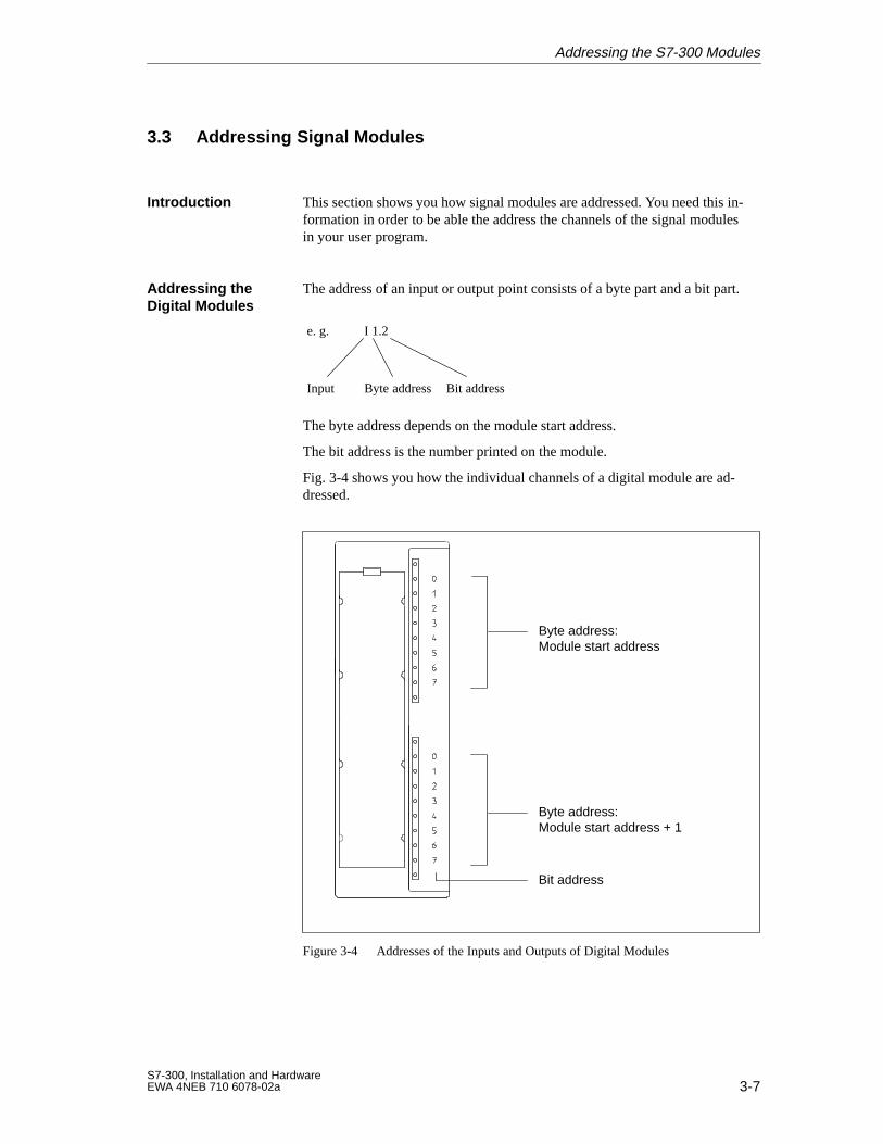
The address of an input or output point consists of a byte part and a bit part.
e. g. I 1.2
Input Byte address Bit address
The byte address depends on the module start address.
The bit address is the number printed on the module.
Fig. 3-4 shows you how the individual channels of a digital module are ad-dressed.
Byte address: Module start address
Byte address: Module start address + 1
Bit address
Figure 3-4 Addresses of the Inputs and Outputs of Digital Modules
Introduction
Addressing theDigital Modules
Addressing the S7-300 Modules
3-8S7-300, Installation and Hardware
EWA 4NEB 710 6078-02a
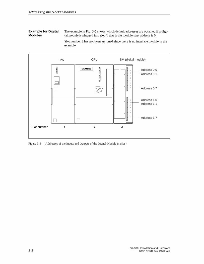
The example in Fig. 3-5 shows which default addresses are obtained if a digi-tal module is plugged into slot 4, that is the module start address is 0.
Slot number 3 has not been assigned since there is no interface module in theexample.
Address 0.0
Address 1.1
Address 0.1
Address 0.7
Address 1.7
Address 1.0
Slot number 1 2 4
PS CPU SM (digital module)
Figure 3-5 Addresses of the Inputs and Outputs of the Digital Module in Slot 4
Example for DigitalModules
Addressing the S7-300 Modules
3-9S7-300, Installation and HardwareEWA 4NEB 710 6078-02a
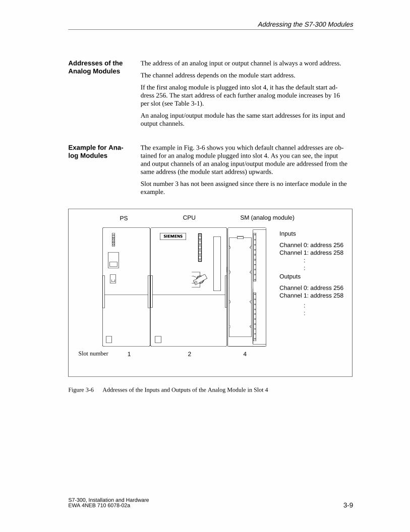
The address of an analog input or output channel is always a word address.
The channel address depends on the module start address.
If the first analog module is plugged into slot 4, it has the default start ad-dress 256. The start address of each further analog module increases by 16per slot (see Table 3-1).
An analog input/output module has the same start addresses for its input andoutput channels.
The example in Fig. 3-6 shows you which default channel addresses are ob-tained for an analog module plugged into slot 4. As you can see, the inputand output channels of an analog input/output module are addressed from thesame address (the module start address) upwards.
Slot number 3 has not been assigned since there is no interface module in theexample.
Slot number 1 2 4
PS CPU SM (analog module)
Inputs
Channel 0: address 256Channel 1: address 258
::
Outputs
Channel 0: address 256Channel 1: address 258
::
Figure 3-6 Addresses of the Inputs and Outputs of the Analog Module in Slot 4
Addresses of theAnalog Modules
Example for Ana -log Modules
Addressing the S7-300 Modules
3-10S7-300, Installation and Hardware
EWA 4NEB 710 6078-02a
3.4 Addressing the Integrated Inputs and Outputs of the CPUs 312 IFMand 314 IFM
The integrated inputs and outputs of the CPU 312 IFM have the followingaddresses:
Table 3-3 Integrated Inputs and Outputs of the CPU 312 IFM
Inputs/Outputs Addresses Remarks
10 digital inputs 124.0 to 125.1
of which 4 special channels:124.6 to 125.1
These special channels can be assigned the functions“Counter” and “Frequency meter” (see IntegratedFunctions Manual) or you can use them as inter-rupt inputs (see Section 10.7.9).
6 digital outputs 124.0 to 124.5 –
The integrated inputs and outputs of the CPU 314 IFM have the followingaddresses:
Table 3-4 Integrated Inputs and Outputs of the CPU 314 IFM
Inputs/Outputs Addresses Remarks
20 digital inputs 124.0 to 126.3
of which 4 special channels:126.0 to 126.3
These special channels can be assigned the functions“Counter”, “Frequency meter”, “Counter A/B” or“Positioning” (see Integrated Functions Manual)or you can use them as interrupt inputs (see Section10.7.9).
16 digital outputs 124.0 to 125.7 –
4 analog inputs 128 to 135 –
1 analog output 128 to 129 –
CPU 312 IFM
CPU 314 IFM
Addressing the S7-300 Modules
4-1S7-300, Installation and HardwareEWA 4NEB 710 6078-02a
Electrical Configuration
You will need to understand the following when installing an S7-300:
The mechanical configuration and
The electrical configuration.
Please therefore also read Chapter 2 “Mechanical Configuration”.
In view of the many and varied applications an S7-300 has, this chapter canonly describe a few basic rules on its electrical configuration. You must ob-serve at least these basic rules if you want your S7-300 to operate faultlesslyand satisfactorily.
This chapter contains the following sections on the electrical configuration ofthe S7-300:
Section Contents Page
4.1 General Rules and Guidelines for Operating an S7-300 Pro-grammable Controller
4-2
4.2 Current Consumption and Power Losses of an S7-300 4-4
4.3 Configuring the S7-300 Process Peripherals 4-8
4.4 S7-300 Configuration with Grounded Reference Potential 4-12
4.5 S7-300 Configuration with Ungrounded Reference Potential(not CPU 312 IFM)
4-13
4.6 S7-300 Configuration with Isolated Modules 4-14
4.7 Configuration of an S7-300 with NON-Isolated Modules 4-16
4.8 Cabling Inside Buildings 4-17
4.9 Cabling Outside Buildings 4-20
4.10 Protecting Digital Output Modules Against Induced Over-voltage
4-21
4.11 Lightning Protection 4-23
Introduction
Basic Rules
In this Chapter
4
4-2S7-300, Installation and Hardware
EWA 4NEB 710 6078-02a
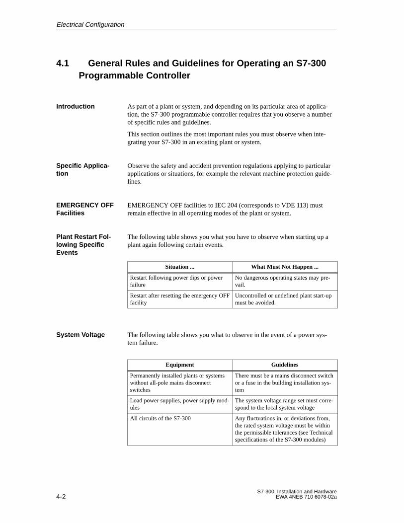
4.1 General Rules and Guidelines for Operating an S7-300 Programmable Controller
As part of a plant or system, and depending on its particular area of applica-tion, the S7-300 programmable controller requires that you observe a numberof specific rules and guidelines.
This section outlines the most important rules you must observe when inte-grating your S7-300 in an existing plant or system.
Observe the safety and accident prevention regulations applying to particularapplications or situations, for example the relevant machine protection guide-lines.
EMERGENCY OFF facilities to IEC 204 (corresponds to VDE 113) mustremain effective in all operating modes of the plant or system.
The following table shows you what you have to observe when starting up aplant again following certain events.
Situation ... What Must Not Happen ...
Restart following power dips or powerfailure
No dangerous operating states may pre-vail.
Restart after resetting the emergency OFFfacility
Uncontrolled or undefined plant start-upmust be avoided.
The following table shows you what to observe in the event of a power sys-tem failure.
Equipment Guidelines
Permanently installed plants or systemswithout all-pole mains disconnectswitches
There must be a mains disconnect switchor a fuse in the building installation sys-tem
Load power supplies, power supply mod-ules
The system voltage range set must corre-spond to the local system voltage
All circuits of the S7-300 Any fluctuations in, or deviations from,the rated system voltage must be withinthe permissible tolerances (see Technicalspecifications of the S7-300 modules)
Introduction
Specific Applica -tion
EMERGENCY OFFFacilities
Plant Restart Fol -lowing SpecificEvents
System V oltage
Electrical Configuration
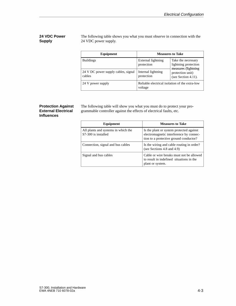
4-3S7-300, Installation and HardwareEWA 4NEB 710 6078-02a
The following table shows you what you must observe in connection with the24 VDC power supply.
Equipment Measures to Take
Buildings External lightningprotection
Take the necessarylightning protectionmeasures (lightning
24 V DC power supply cables, signalcables
Internal lightningprotection
measures (lightningprotection unit)(see Section 4.11).
24 V power supply Reliable electrical isolation of the extra-lowvoltage
The following table will show you what you must do to protect your pro-grammable controller against the effects of electrical faults, etc.
Equipment Measures to Take
All plants and systems in which theS7-300 is installed
Is the plant or system protected againstelectromagnetic interference by connec-tion to a protective ground conductor?
Connection, signal and bus cables Is the wiring and cable routing in order?(see Sections 4.8 and 4.9)
Signal and bus cables Cable or wire breaks must not be allowedto result in indefined situations in theplant or system.
24 VDC PowerSupply
Protection AgainstExternal ElectricalInfluences
Electrical Configuration
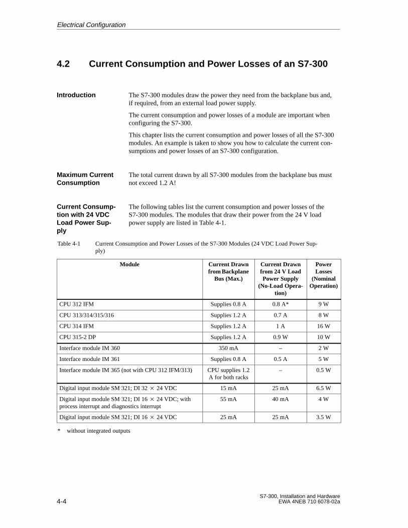
4-4S7-300, Installation and Hardware
EWA 4NEB 710 6078-02a
4.2 Current Consumption and Power Losses of an S7-300
The S7-300 modules draw the power they need from the backplane bus and,if required, from an external load power supply.
The current consumption and power losses of a module are important whenconfiguring the S7-300.
This chapter lists the current consumption and power losses of all the S7-300modules. An example is taken to show you how to calculate the current con-sumptions and power losses of an S7-300 configuration.
The total current drawn by all S7-300 modules from the backplane bus mustnot exceed 1.2 A!
The following tables list the current consumption and power losses of theS7-300 modules. The modules that draw their power from the 24 V loadpower supply are listed in Table 4-1.
Table 4-1 Current Consumption and Power Losses of the S7-300 Modules (24 VDC Load Power Sup-ply)
Module Current Drawnfrom Backplane
Bus (Max.)
Current Drawnfrom 24 V LoadPower Supply
(No-Load Opera-tion)
PowerLosses
(NominalOperation)
CPU 312 IFM Supplies 0.8 A 0.8 A* 9 W
CPU 313/314/315/316 Supplies 1.2 A 0.7 A 8 W
CPU 314 IFM Supplies 1.2 A 1 A 16 W
CPU 315-2 DP Supplies 1.2 A 0.9 W 10 W
Interface module IM 360 350 mA – 2 W
Interface module IM 361 Supplies 0.8 A 0.5 A 5 W
Interface module IM 365 (not with CPU 312 IFM/313) CPU supplies 1.2A for both racks
– 0.5 W
Digital input module SM 321; DI 32 24 VDC 15 mA 25 mA 6.5 W
Digital input module SM 321; DI 16 24 VDC; withprocess interrupt and diagnostics interrupt
55 mA 40 mA 4 W
Digital input module SM 321; DI 16 24 VDC 25 mA 25 mA 3.5 W
* without integrated outputs
Introduction
Maximum CurrentConsumption
Current Consump -tion with 24 VDCLoad Power Sup -ply
Electrical Configuration
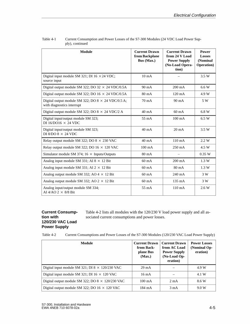
4-5S7-300, Installation and HardwareEWA 4NEB 710 6078-02a
Table 4-1 Current Consumption and Power Losses of the S7-300 Modules (24 VDC Load Power Sup-ply), continued
Module PowerLosses
(NominalOperation)
Current Drawnfrom 24 V LoadPower Supply
(No-Load Opera-tion)
Current Drawnfrom Backplane
Bus (Max.)
Digital input module SM 321; DI 16 24 VDC; source input
10 mA – 3.5 W
Digital output module SM 322; DO 32 24 VDC/0.5A 90 mA 200 mA 6.6 W
Digital output module SM 322; DO 16 24 VDC/0.5A 80 mA 120 mA 4.9 W
Digital output module SM 322; DO 8 24 VDC/0.5 A;with diagnostics interrupt
70 mA 90 mA 5 W
Digital output module SM 322; DO 8 24 VDC/2 A 40 mA 60 mA 6.8 W
Digital input/output module SM 323; DI 16/DO16 24 VDC
55 mA 100 mA 6.5 W
Digital input/output module SM 323; DI 8/DO 8 24 VDC
40 mA 20 mA 3.5 W
Relay output module SM 322; DO 8 230 VAC 40 mA 110 mA 2.2 W
Relay output module SM 322; DO 16 120 VAC 100 mA 250 mA 4.5 W
Simulator module SM 374; 16 Inputs/Outputs 80 mA – 0.35 W
Analog input module SM 331; AI 8 12 Bit 60 mA 200 mA 1.3 W
Analog input module SM 331; AI 2 12 Bit 60 mA 80 mA 1.3 W
Analog output module SM 332; AO 4 12 Bit 60 mA 240 mA 3 W
Analog output module SM 332; AO 2 12 Bit 60 mA 135 mA 3 W
Analog input/output module SM 334;AI 4/AO 2 8/8 Bit
55 mA 110 mA 2.6 W
Table 4-2 lists all modules with the 120/230 V load power supply and all as-sociated current consumptions and power losses.
Table 4-2 Current Consumptions and Power Losses of the S7-300 Modules (120/230 VAC Load Power Supply)
Module Current Drawnfrom Back-plane Bus
(Max.)
Current Drawnfrom AC LoadPower Supply(No-Load Op-
eration)
Power Losses(Nominal Op-
eration)
Digital input module SM 321; DI 8 120/230 VAC 29 mA – 4.9 W
Digital input module SM 321; DI 16 120 VAC 16 mA – 4.1 W
Digital output module SM 322; DO 8 120/230 VAC 100 mA 2 mA 8.6 W
Digital output module SM 322; DO 16 120 VAC 184 mA 3 mA 9.0 W
Current Consump -tion with120/230 VAC LoadPower Supply
Electrical Configuration
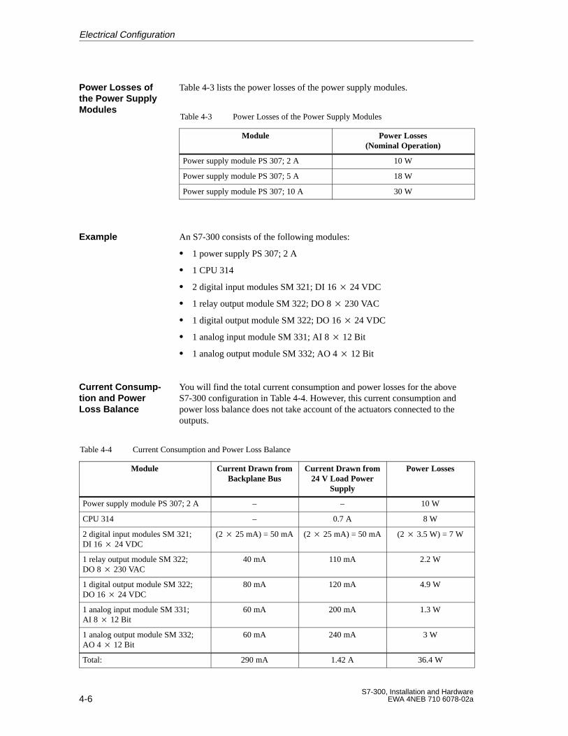
4-6S7-300, Installation and Hardware
EWA 4NEB 710 6078-02a
Table 4-3 lists the power losses of the power supply modules.
Table 4-3 Power Losses of the Power Supply Modules
Module Power Losses(Nominal Operation)
Power supply module PS 307; 2 A 10 W
Power supply module PS 307; 5 A 18 W
Power supply module PS 307; 10 A 30 W
An S7-300 consists of the following modules:
1 power supply PS 307; 2 A
1 CPU 314
2 digital input modules SM 321; DI 16 24 VDC
1 relay output module SM 322; DO 8 230 VAC
1 digital output module SM 322; DO 16 24 VDC
1 analog input module SM 331; AI 8 12 Bit
1 analog output module SM 332; AO 4 12 Bit
You will find the total current consumption and power losses for the aboveS7-300 configuration in Table 4-4. However, this current consumption andpower loss balance does not take account of the actuators connected to theoutputs.
Table 4-4 Current Consumption and Power Loss Balance
Module Current Drawn fromBackplane Bus
Current Drawn from24 V Load Power
Supply
Power Losses
Power supply module PS 307; 2 A – – 10 W
CPU 314 – 0.7 A 8 W
2 digital input modules SM 321;DI 16 24 VDC
(2 25 mA) = 50 mA (2 25 mA) = 50 mA (2 3.5 W) = 7 W
1 relay output module SM 322;DO 8 230 VAC
40 mA 110 mA 2.2 W
1 digital output module SM 322;DO 16 24 VDC
80 mA 120 mA 4.9 W
1 analog input module SM 331; AI 8 12 Bit
60 mA 200 mA 1.3 W
1 analog output module SM 332;AO 4 12 Bit
60 mA 240 mA 3 W
Total: 290 mA 1.42 A 36.4 W
Power Losses ofthe Power SupplyModules
Example
Current Consump -tion and PowerLoss Balance
Electrical Configuration
4-7S7-300, Installation and HardwareEWA 4NEB 710 6078-02a
The following results are obtained from Table 4-4:
1. Current drawn from the backplane bus:
The total current drawn by the signal modules from the backplane bus is290 mA, and therefore does not exceed the 1.2 A the CPU 314 supplies tothe backplane bus.
2. Current drawn from the 24 V load power supply:
The total current drawn by the signal modules from the 24 V load powersupply is approximately 1.5 A.In addition, you must take into account all other loads connected. De-pending thereon, you select the PS 307 power supply.
3. Power losses:
The total power losses of the S7-300 configuration are 36.4 W.
The total power losses of all the components installed in a cabinet (in-cluding the S7-300 with 36.4 W) must not exceed the maximum powerthat can be dissipated from the cabinet.
Tip: When fixing the dimensions of the cabinet, ensure that the tempera-ture inside the cabinet does not exceed the permissible 60 C (140 F)even where external temperatures are high.
Result
Electrical Configuration
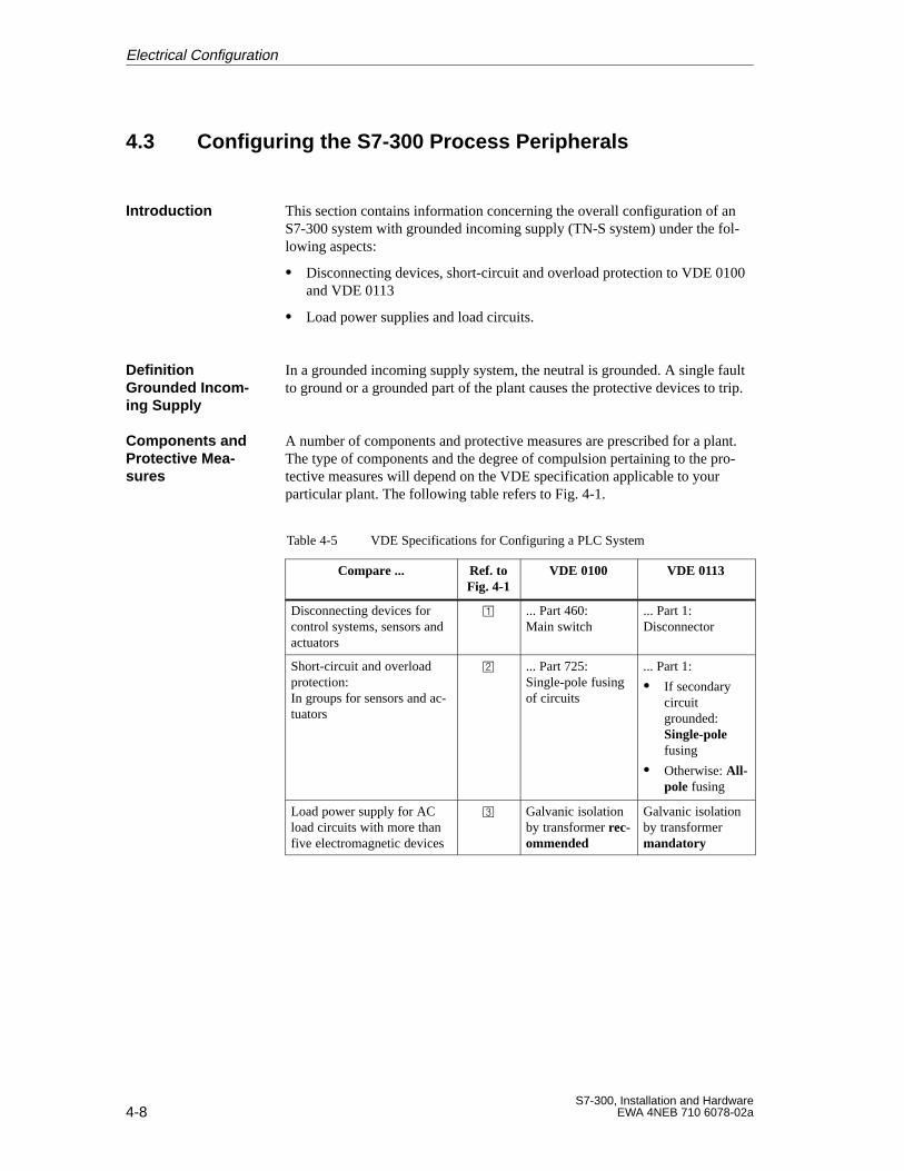
4-8S7-300, Installation and Hardware
EWA 4NEB 710 6078-02a
4.3 Configuring the S7-300 Process Peripherals
This section contains information concerning the overall configuration of anS7-300 system with grounded incoming supply (TN-S system) under the fol-lowing aspects:
Disconnecting devices, short-circuit and overload protection to VDE 0100and VDE 0113
Load power supplies and load circuits.
In a grounded incoming supply system, the neutral is grounded. A single faultto ground or a grounded part of the plant causes the protective devices to trip.
A number of components and protective measures are prescribed for a plant.The type of components and the degree of compulsion pertaining to the pro-tective measures will depend on the VDE specification applicable to yourparticular plant. The following table refers to Fig. 4-1.
Table 4-5 VDE Specifications for Configuring a PLC System
Compare ... Ref. toFig. 4-1
VDE 0100 VDE 0113
Disconnecting devices forcontrol systems, sensors andactuators
... Part 460:Main switch
... Part 1:Disconnector
Short-circuit and overloadprotection:In groups for sensors and ac-tuators
... Part 725:Single-pole fusingof circuits
... Part 1:
If secondarycircuitgrounded:Single-polefusing
Otherwise: All-pole fusing
Load power supply for ACload circuits with more thanfive electromagnetic devices
Galvanic isolationby transformer rec-ommended
Galvanic isolationby transformermandatory
Introduction
DefinitionGrounded Incom -ing Supply
Components andProtective Mea -sures
Electrical Configuration

4-9S7-300, Installation and HardwareEWA 4NEB 710 6078-02a
The load power supply powers input and output circuits (load circuits), aswell as sensors and actuators. The characteristic features of load power sup-plies required in specific applications are listed in the following table.
Characteristics ofthe Load Power
Supply
Mandatory for ... Remarks
Reliable separation Modules that have to bepowered with 60 VDC or25 VAC
The PS 307 power supply andthe Siemens load power suppliesof the 6EP1 series have thesecharacteristics
24 VDC load circuits
Output voltage toler-ances:20.4 V to 28.8 V
40.8 V to 57.6 V
51 V to 72 V
24 VDC load circuits
48 VDC load circuits
60 VDC load circuits
If the output voltage tolerancesare exceeded, we recommendyou fit a back-up capacitor ratedat 200 F for each ampere ofload current (with bridge rectifi-cation).
Load circuits should be grounded.
The common reference potential (ground) guarantees full functionality. Pro-vide a detachable link to the protective ground conductor on the load powersupply (terminal L- or M) or on the isolating transformer (Fig. 4-1, ). Inthe event of power distribution faults, this makes it easier to localize groundfaults.
A separate S7-300 grounding concept exists for the CPU 312 IFM and theCPUs 313/314/314 IFM/315/315-2 DP/316.
CPU 312 IFM:With the CPU 312 IFM, you can implement only agrounded configuration. Functional ground is connected with chassisground internally in CPU 312 IFM (see Section 10.8.1).
CPUs 313/314/314 IFM/315/315-2 DP/316: If you operate the S7-300with the CPUs 313/314/315/315-2 DP/316 on a grounded incoming sup-ply, you should also ground the S7-300’s reference potential. The refer-ence potential is grounded if the link between the M terminal and thefunctional ground terminal on the CPUs is in place (factory setting of theCPU).
Characteristics ofLoad Power Sup -plies
Rule: Ground allLoad Circuits
Grounding Con-cept for the S7-300
Electrical Configuration
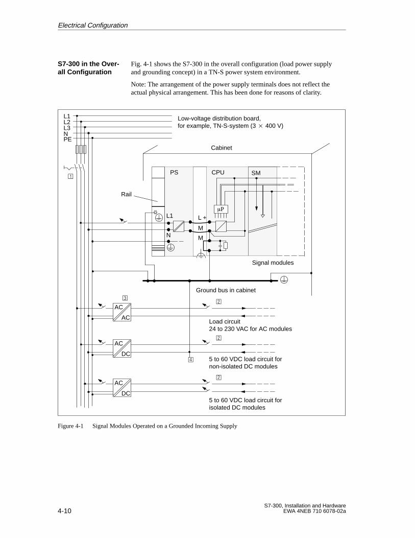
4-10S7-300, Installation and Hardware
EWA 4NEB 710 6078-02a
Fig. 4-1 shows the S7-300 in the overall configuration (load power supplyand grounding concept) in a TN-S power system environment.
Note: The arrangement of the power supply terminals does not reflect theactual physical arrangement. This has been done for reasons of clarity.
Ground bus in cabinet
N M
L1 L +
M
PS CPU
P
L1L2L3N
Load circuit 24 to 230 VAC for AC modules
5 to 60 VDC load circuit for non-isolated DC modules
5 to 60 VDC load circuit for isolated DC modules
Cabinet
AC
AC
AC
DC
AC
DC
Signal modules
Low-voltage distribution board, for example, TN-S-system (3 400 V)
PE
SM
Rail
Figure 4-1 Signal Modules Operated on a Grounded Incoming Supply
S7-300 in the Over -all Configuration
Electrical Configuration
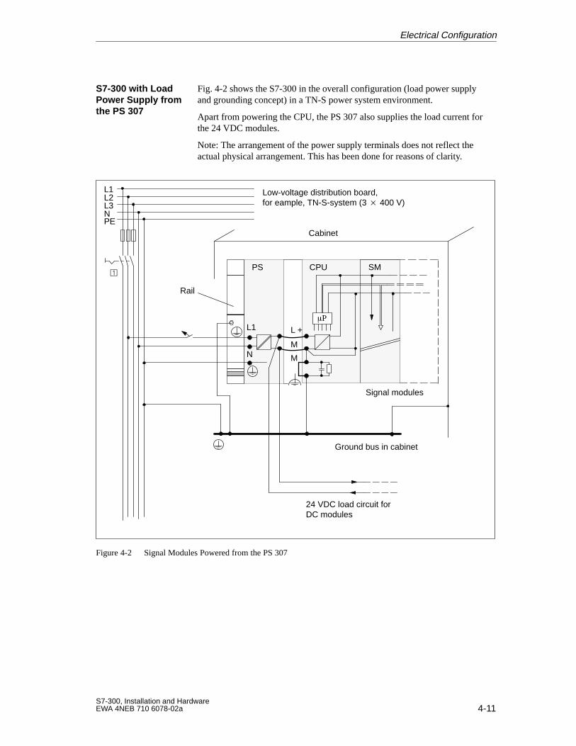
4-11S7-300, Installation and HardwareEWA 4NEB 710 6078-02a
Fig. 4-2 shows the S7-300 in the overall configuration (load power supplyand grounding concept) in a TN-S power system environment.
Apart from powering the CPU, the PS 307 also supplies the load current forthe 24 VDC modules.
Note: The arrangement of the power supply terminals does not reflect theactual physical arrangement. This has been done for reasons of clarity.
N M
L1 L +
M
PS CPU
P
L1L2L3N
24 VDC load circuit forDC modules
Ground bus in cabinet
Cabinet
Signal modules
Low-voltage distribution board, for eample, TN-S-system (3 400 V)
PE
SM
Rail
Figure 4-2 Signal Modules Powered from the PS 307
S7-300 with LoadPower Supply fromthe PS 307
Electrical Configuration
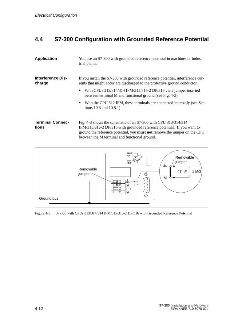
4-12S7-300, Installation and Hardware
EWA 4NEB 710 6078-02a
4.4 S7-300 Configuration with Grounded Reference Potential
You use an S7-300 with grounded reference potential in machines or indus-trial plants.
If you install the S7-300 with grounded reference potential, interference cur-rents that might occur are discharged to the protective ground conductor.
With CPUs 313/314/314 IFM/315/315-2 DP/316 via a jumper insertedbetween terminal M and functional ground (see Fig. 4-3)
With the CPU 312 IFM, these terminals are connected internally (see Sec-tions 10.3 and 10.8.1)
Fig. 4-3 shows the schematic of an S7-300 with CPU 313/314/314IFM/315/315-2 DP/316 with grounded reference potential. If you want toground the reference potential, you must not remove the jumper on the CPUbetween the M terminal and functional ground.
ML +M
M
47 nF 1 MΩ
Ground bus
Removablejumper
Removablejumper
Figure 4-3 S7-300 with CPUs 313/314/314 IFM/315/315-2 DP/316 with Grounded Reference Potential
Application
Interference Dis-charge
Terminal Connec -tions
Electrical Configuration
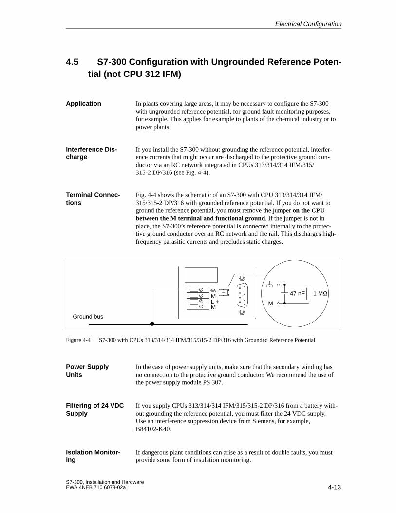
4-13S7-300, Installation and HardwareEWA 4NEB 710 6078-02a
4.5 S7-300 Configuration with Ungrounded Reference Poten -tial (not CPU 312 IFM)
In plants covering large areas, it may be necessary to configure the S7-300with ungrounded reference potential, for ground fault monitoring purposes,for example. This applies for example to plants of the chemical industry or topower plants.
If you install the S7-300 without grounding the reference potential, interfer-ence currents that might occur are discharged to the protective ground con-ductor via an RC network integrated in CPUs 313/314/314 IFM/315/315-2 DP/316 (see Fig. 4-4).
Fig. 4-4 shows the schematic of an S7-300 with CPU 313/314/314 IFM/315/315-2 DP/316 with grounded reference potential. If you do not want toground the reference potential, you must remove the jumper on the CPUbetween the M terminal and functional ground. If the jumper is not inplace, the S7-300’s reference potential is connected internally to the protec-tive ground conductor over an RC network and the rail. This discharges high-frequency parasitic currents and precludes static charges.
ML +M
M
47 nF 1 MΩ
Ground bus
Figure 4-4 S7-300 with CPUs 313/314/314 IFM/315/315-2 DP/316 with Grounded Reference Potential
In the case of power supply units, make sure that the secondary winding hasno connection to the protective ground conductor. We recommend the use ofthe power supply module PS 307.
If you supply CPUs 313/314/314 IFM/315/315-2 DP/316 from a battery with-out grounding the reference potential, you must filter the 24 VDC supply.Use an interference suppression device from Siemens, for example,B84102-K40.
If dangerous plant conditions can arise as a result of double faults, you mustprovide some form of insulation monitoring.
Application
Interference Dis-charge
Terminal Connec -tions
Power SupplyUnits
Filtering of 24 VDCSupply
Isolation Monitor-ing
Electrical Configuration
4-14S7-300, Installation and Hardware
EWA 4NEB 710 6078-02a
4.6 S7-300 Configuration with Isolated Modules
In configurations with isolated modules, the reference potentials of the con-trol circuit (Mint) and load circuit (Mext) are galvanically isolated(see Fig. 4-5).
You use isolated modules for the following:
AC load circuits
DC load circuits with separate reference potential
Examples of load circuits with separate reference potential:
– DC load circuits whose sensors have different reference potentials (forexample if grounded sensors are located at some considerable distancefrom the control system and no equipotential bonding is possible)
– DC load circuits whose positive pole (L+) is grounded (battery cir-cuits).
You can use isolated modules irrespective of whether the reference potentialof the control system is grounded or not.
Definition
Applications
Isolated Modulesand GroundingConcept
Electrical Configuration
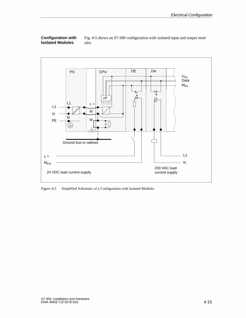
4-15S7-300, Installation and HardwareEWA 4NEB 710 6078-02a
Fig. 4-5 shows an S7-300 configuration with isolated input and output mod-ules.
NM
L1 L +
M
PS CPU
P
L1
N
24 VDC load current supply
Mext
L +
Uint
Mint
Data
L1
N
DE DA
PE
230 VAC loadcurrent supply
Ground bus in cabinet
Figure 4-5 Simplified Schematic of a Configuration with Isolated Modules
Configuration withIsolated Modules
Electrical Configuration
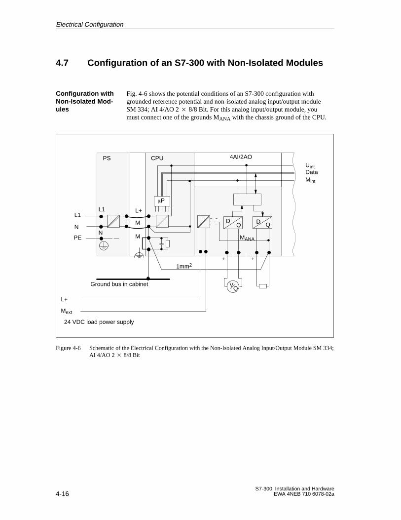
4-16S7-300, Installation and Hardware
EWA 4NEB 710 6078-02a
4.7 Configuration of an S7-300 with Non-Isolated Modules
Fig. 4-6 shows the potential conditions of an S7-300 configuration withgrounded reference potential and non-isolated analog input/output moduleSM 334; AI 4/AO 2 8/8 Bit. For this analog input/output module, youmust connect one of the grounds MANA with the chassis ground of the CPU.
L+
NM
L1 L+
M
PS CPU
P
L1
N
24 VDC load power supply
Uint
Mint
Data
4AI/2AO
PE
1mm2
MANA
Ground bus in cabinet
Mext
VQ
+ +
DQ Q
D
Figure 4-6 Schematic of the Electrical Configuration with the Non-Isolated Analog Input/Output Module SM 334;AI 4/AO 2 8/8 Bit
Configuration withNon-Isolated Mod-ules
Electrical Configuration
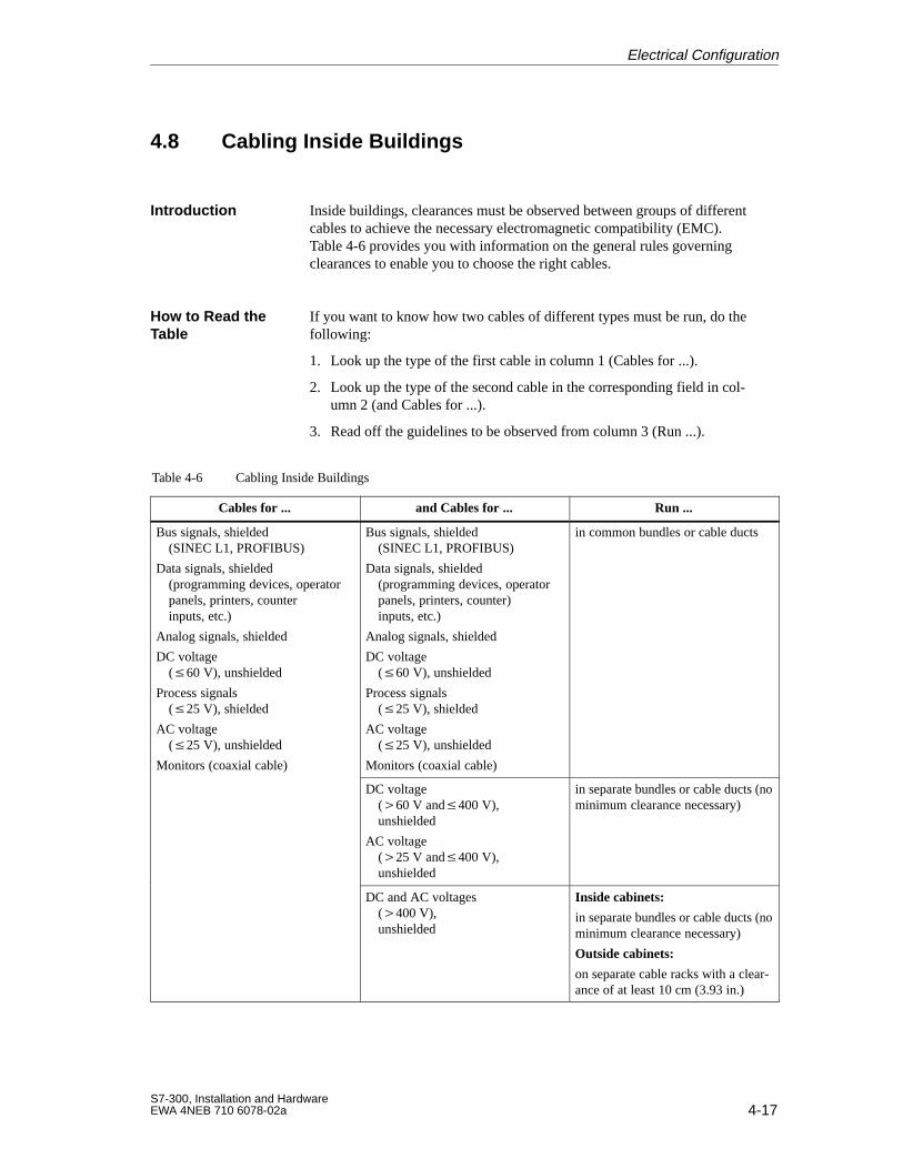
4-17S7-300, Installation and HardwareEWA 4NEB 710 6078-02a
4.8 Cabling Inside Buildings
Inside buildings, clearances must be observed between groups of differentcables to achieve the necessary electromagnetic compatibility (EMC).Table 4-6 provides you with information on the general rules governingclearances to enable you to choose the right cables.
If you want to know how two cables of different types must be run, do thefollowing:
1. Look up the type of the first cable in column 1 (Cables for ...).
2. Look up the type of the second cable in the corresponding field in col-umn 2 (and Cables for ...).
3. Read off the guidelines to be observed from column 3 (Run ...).
Table 4-6 Cabling Inside Buildings
Cables for ... and Cables for ... Run ...
Bus signals, shielded(SINEC L1, PROFIBUS)
Data signals, shielded (programming devices, operatorpanels, printers, counterinputs, etc.)
Analog signals, shielded
DC voltage(60 V), unshielded
Process signals(25 V), shielded
AC voltage(25 V), unshielded
Monitors (coaxial cable)
Bus signals, shielded(SINEC L1, PROFIBUS)
Data signals, shielded(programming devices, operatorpanels, printers, counter)inputs, etc.)
Analog signals, shielded
DC voltage(60 V), unshielded
Process signals(25 V), shielded
AC voltage(25 V), unshielded
Monitors (coaxial cable)
in common bundles or cable ducts
DC voltage(60 V and400 V),unshielded
AC voltage(25 V and400 V),unshielded
in separate bundles or cable ducts (nominimum clearance necessary)
DC and AC voltages(400 V), unshielded
Inside cabinets:
in separate bundles or cable ducts (nominimum clearance necessary)
Outside cabinets:
on separate cable racks with a clear-ance of at least 10 cm (3.93 in.)
Introduction
How to Read theTable
Electrical Configuration
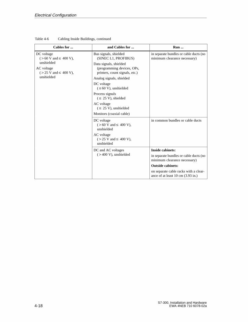
4-18S7-300, Installation and Hardware
EWA 4NEB 710 6078-02a
Table 4-6 Cabling Inside Buildings, continued
Cables for ... and Cables for ... Run ...
DC voltage(60 V and 400 V),unshielded
AC voltage(25 V and 400 V), unshielded
Bus signals, shielded(SINEC L1, PROFIBUS)
Data signals, shielded(programming devices, OPs,printers, count signals, etc.)
Analog signals, shielded
DC voltage(60 V), unshielded
Process signals( 25 V), shielded
AC voltage( 25 V), unshielded
Monitors (coaxial cable)
in separate bundles or cable ducts (nominimum clearance necessary)
DC voltage(60 V and 400 V),unshielded
AC voltage(25 V and 400 V), unshielded
in common bundles or cable ducts
DC and AC voltages(400 V), unshielded
Inside cabinets:
in separate bundles or cable ducts (nominimum clearance necessary)
Outside cabinets:
on separate cable racks with a clear-ance of at least 10 cm (3.93 in.)
Electrical Configuration
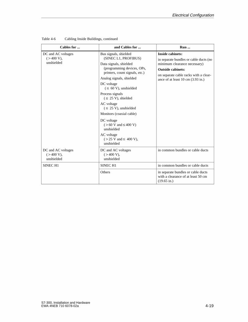
4-19S7-300, Installation and HardwareEWA 4NEB 710 6078-02a
Table 4-6 Cabling Inside Buildings, continued
Cables for ... and Cables for ... Run ...
DC and AC voltages(400 V), unshielded
Bus signals, shielded(SINEC L1, PROFIBUS)
Data signals, shielded(programming devices, OPs,printers, count signals, etc.)
Analog signals, shielded
DC voltage ( 60 V), unshielded
Process signals( 25 V), shielded
AC voltage( 25 V), unshielded
Monitors (coaxial cable)
Inside cabinets:
in separate bundles or cable ducts (nominimum clearance necessary)
Outside cabinets:
on separate cable racks with a clear-ance of at least 10 cm (3.93 in.)
DC voltage(60 V and400 V)unshielded
AC voltage(25 V and 400 V), unshielded
DC and AC voltages(400 V), unshielded
DC and AC voltages(400 V), unshielded
in common bundles or cable ducts
SINEC H1 SINEC H1 in common bundles or cable ducts
Others in separate bundles or cable ductswith a clearance of at least 50 cm(19.65 in.)
Electrical Configuration
4-20S7-300, Installation and Hardware
EWA 4NEB 710 6078-02a
4.9 Cabling Outside Buildings
When installing cables outside buildings, the same EMC rules apply as forinside buildings. The following also applies:
Run cables on metallic cable supports.
Establish a metallic connection between the joints in the cable supports
Ground the cable supports
If necessary, provide adequate equipotential bonding between the variousitems of equipment connected.
Take the necessary (internal and external) lightning protection andgrounding measures applying to your particular application (see below).
Run your cables either
in metallic conduits grounded at both ends, or
in concrete cable ducts with continuous end-to-end armoring
An individual appraisal of the entire plant is necessary before initiating anylightning protection measures (see Section 4.11).
Rules for EMC
Rules for Govern -ing LightningProtection OutsideBuildings
OvervoltageProtection Devices
Electrical Configuration
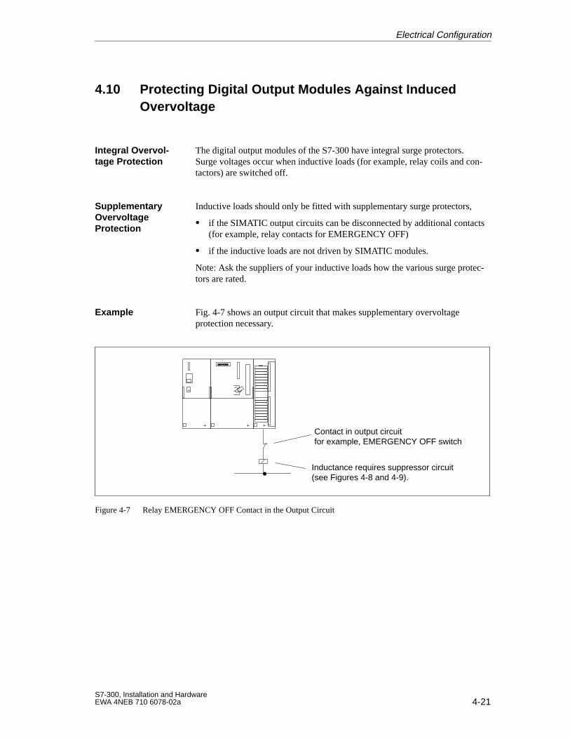
4-21S7-300, Installation and HardwareEWA 4NEB 710 6078-02a
4.10 Protecting Digital Output Modules Against Induced Overvoltage
The digital output modules of the S7-300 have integral surge protectors.Surge voltages occur when inductive loads (for example, relay coils and con-tactors) are switched off.
Inductive loads should only be fitted with supplementary surge protectors,
if the SIMATIC output circuits can be disconnected by additional contacts(for example, relay contacts for EMERGENCY OFF)
if the inductive loads are not driven by SIMATIC modules.
Note: Ask the suppliers of your inductive loads how the various surge protec-tors are rated.
Fig. 4-7 shows an output circuit that makes supplementary overvoltageprotection necessary.
Contact in output circuitfor example, EMERGENCY OFF switch
Inductance requires suppressor circuit(see Figures 4-8 and 4-9).
Figure 4-7 Relay EMERGENCY OFF Contact in the Output Circuit
Integral Overvol -tage Protection
SupplementaryOvervoltageProtection
Example
Electrical Configuration
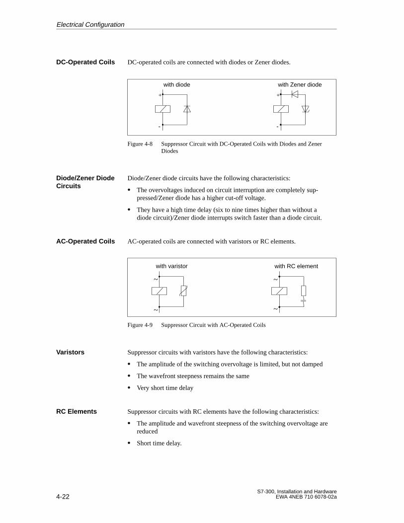
4-22S7-300, Installation and Hardware
EWA 4NEB 710 6078-02a
DC-operated coils are connected with diodes or Zener diodes.
+
-
+
-
with diode with Zener diode
Figure 4-8 Suppressor Circuit with DC-Operated Coils with Diodes and ZenerDiodes
Diode/Zener diode circuits have the following characteristics:
The overvoltages induced on circuit interruption are completely sup-pressed/Zener diode has a higher cut-off voltage.
They have a high time delay (six to nine times higher than without adiode circuit)/Zener diode interrupts switch faster than a diode circuit.
AC-operated coils are connected with varistors or RC elements.
with varistor with RC element
~
~
~
~
Figure 4-9 Suppressor Circuit with AC-Operated Coils
Suppressor circuits with varistors have the following characteristics:
The amplitude of the switching overvoltage is limited, but not damped
The wavefront steepness remains the same
Very short time delay
Suppressor circuits with RC elements have the following characteristics:
The amplitude and wavefront steepness of the switching overvoltage arereduced
Short time delay.
DC-Operated Coils
Diode/Zener DiodeCircuits
AC-Operated Coils
Varistors
RC Elements
Electrical Configuration
4-23S7-300, Installation and HardwareEWA 4NEB 710 6078-02a
4.11 Lightning Protection
The following section shows you possible solutions to protect your S7-300against the effects of overvoltages.
The solutions given are based on the lightning protection zone concept that isdescribed in the IEC 1312-1 “Protection against LEMP”.
Failures are very often the result of overvoltages caused by:
Atmospheric discharge or
Electrostatic discharge.
First of all, we want to introduce you to the lightning protection zone con-cept, on which the protection against overvoltage is based.
At the end of this section, you will find rules for the transitions between theindividual lightning protection zones.
Note
This section can only provide information on the protection of a program-mable controller against overvoltages.
However, a complete protection against overvoltage is guaranteed only if thewhole surrounding building is designed to provide protection against over-voltages. This refers especially to constructional measures for the buildingalready in the planning phase.
If you wish to obtain detailed information on overvoltage protection, wetherefore recommend you to address your Siemens contact or a companyspecialized in lightning protection.
Introduction
Reference Literature
Overview
Electrical Configuration
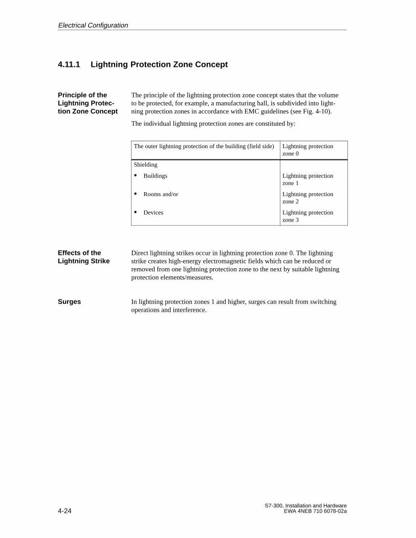
4-24S7-300, Installation and Hardware
EWA 4NEB 710 6078-02a
4.11.1 Lightning Protection Zone Concept
The principle of the lightning protection zone concept states that the volumeto be protected, for example, a manufacturing hall, is subdivided into light-ning protection zones in accordance with EMC guidelines (see Fig. 4-10).
The individual lightning protection zones are constituted by:
The outer lightning protection of the building (field side)Lightning protectionzone 0
Shielding
Buildings Lightning protectionzone 1
Rooms and/or Lightning protectionzone 2
Devices Lightning protectionzone 3
Direct lightning strikes occur in lightning protection zone 0. The lightningstrike creates high-energy electromagnetic fields which can be reduced orremoved from one lightning protection zone to the next by suitable lightningprotection elements/measures.
In lightning protection zones 1 and higher, surges can result from switchingoperations and interference.
Principle of theLightning Protec-tion Zone Concept
Effects of theLightning Strike
Surges
Electrical Configuration
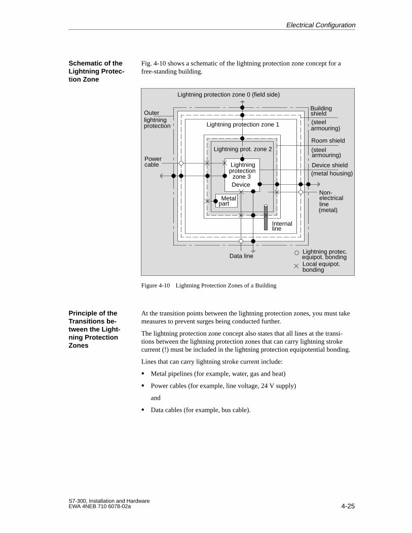
4-25S7-300, Installation and HardwareEWA 4NEB 710 6078-02a
Fig. 4-10 shows a schematic of the lightning protection zone concept for afree-standing building.
Lightning protection zone 0 (field side)
Lightning prot. zone 2
Lightningprotection
zone 3Device
Powercable
Lightning protection zone 1
BuildingOuterlightning
shield(steelarmouring)
Room shield
(steelarmouring)
Device shield(metal housing)
Non-electricalline(metal)
Lightning protec.equipot. bondingData line
bondingLocal equipot.
lineInternal
protection
Metalpart
Figure 4-10 Lightning Protection Zones of a Building
At the transition points between the lightning protection zones, you must takemeasures to prevent surges being conducted further.
The lightning protection zone concept also states that all lines at the transi-tions between the lightning protection zones that can carry lightning strokecurrent (!) must be included in the lightning protection equipotential bonding.
Lines that can carry lightning stroke current include:
Metal pipelines (for example, water, gas and heat)
Power cables (for example, line voltage, 24 V supply)
and
Data cables (for example, bus cable).
Schematic of theLightning Protec-tion Zone
Principle of theTransitions be-tween the Light-ning ProtectionZones
Electrical Configuration
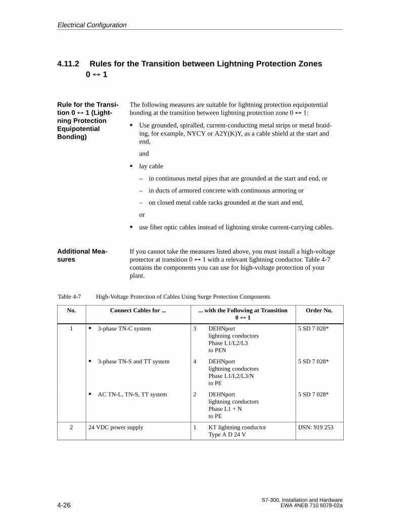
4-26S7-300, Installation and Hardware
EWA 4NEB 710 6078-02a
4.11.2 Rules for the Transition between Lightning Protection Zones0 1
The following measures are suitable for lightning protection equipotentialbonding at the transition between lightning protection zone 0 1:
Use grounded, spiralled, current-conducting metal strips or metal braid-ing, for example, NYCY or A2Y(K)Y, as a cable shield at the start andend,
and
lay cable
– in continuous metal pipes that are grounded at the start and end, or
– in ducts of armored concrete with continuous armoring or
– on closed metal cable racks grounded at the start and end,
or
use fiber optic cables instead of lightning stroke current-carrying cables.
If you cannot take the measures listed above, you must install a high-voltageprotector at transition 0 1 with a relevant lightning conductor. Table 4-7contains the components you can use for high-voltage protection of yourplant.
Table 4-7 High-Voltage Protection of Cables Using Surge Protection Components
No. Connect Cables for ... ... with the Following at Transition0 1
Order No.
1 3-phase TN-C system 3 DEHNportlightning conductorsPhase L1/L2/L3to PEN
5 SD 7 028*
3-phase TN-S and TT system 4 DEHNportlightning conductorsPhase L1/L2/L3/Nto PE
5 SD 7 028*
AC TN-L, TN-S, TT system 2 DEHNportlightning conductorsPhase L1 + Nto PE
5 SD 7 028*
2 24 VDC power supply 1 KT lightning conductorType A D 24 V
DSN: 919 253
Rule for the Transi-tion 0 1 (Light-ning ProtectionEquipotentialBonding)
Additional Mea-sures
Electrical Configuration
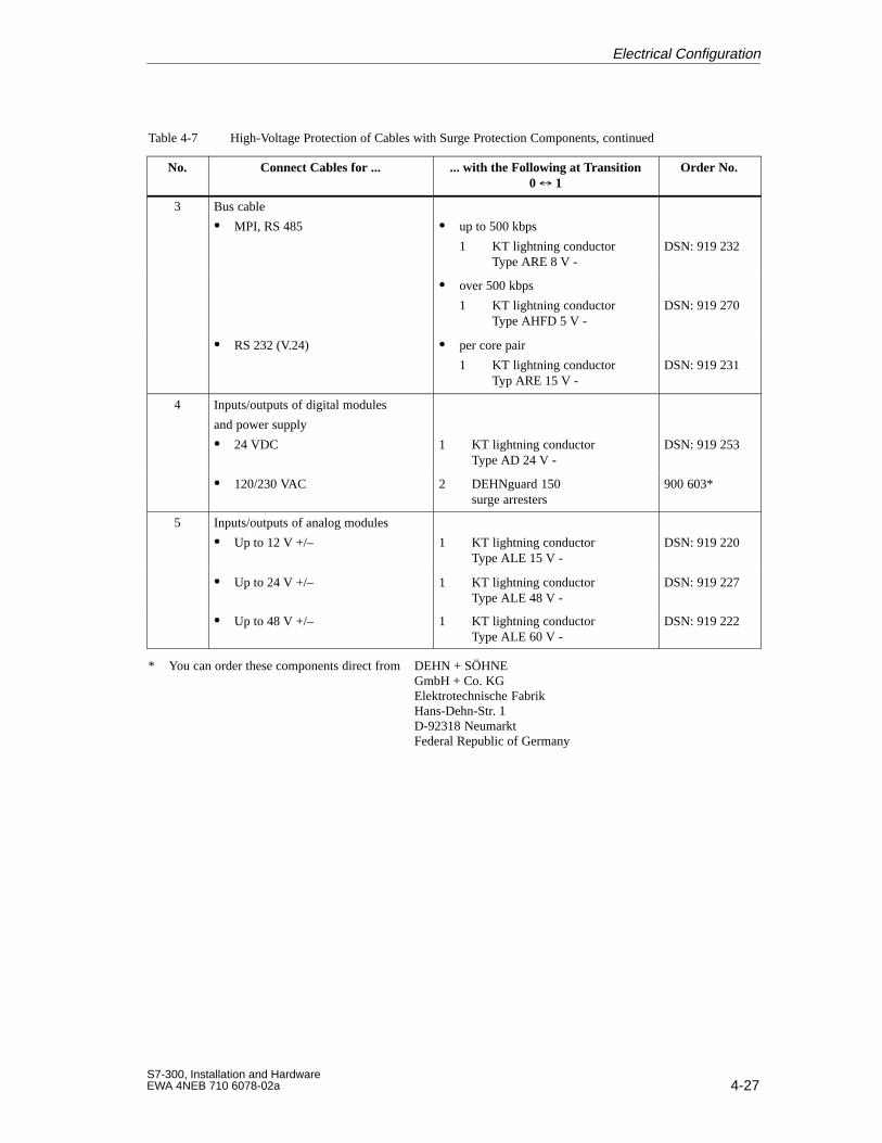
4-27S7-300, Installation and HardwareEWA 4NEB 710 6078-02a
Table 4-7 High-Voltage Protection of Cables with Surge Protection Components, continued
No. Connect Cables for ... ... with the Following at Transition0 1
Order No.
3 Bus cable
MPI, RS 485 up to 500 kbps
1 KT lightning conductorType ARE 8 V -
DSN: 919 232
over 500 kbps
1 KT lightning conductorType AHFD 5 V -
DSN: 919 270
RS 232 (V.24) per core pair
1 KT lightning conductorTyp ARE 15 V -
DSN: 919 231
4 Inputs/outputs of digital modules
and power supply
24 VDC 1 KT lightning conductorType AD 24 V -
DSN: 919 253
120/230 VAC 2 DEHNguard 150surge arresters
900 603*
5 Inputs/outputs of analog modules
Up to 12 V +/– 1 KT lightning conductorType ALE 15 V -
DSN: 919 220
Up to 24 V +/– 1 KT lightning conductorType ALE 48 V -
DSN: 919 227
Up to 48 V +/– 1 KT lightning conductorType ALE 60 V -
DSN: 919 222
* You can order these components direct from DEHN + SÖHNEGmbH + Co. KGElektrotechnische FabrikHans-Dehn-Str. 1D-92318 NeumarktFederal Republic of Germany
Electrical Configuration

4-28S7-300, Installation and Hardware
EWA 4NEB 710 6078-02a
4.11.3 Rules for Transition between Lightning Protection Zones 1 2and Greater
The following applies for all lightning protection zone transitions 1 2 andgreater:
Set up local equipotential bonding at each subsequent lightning protectionzone transition.
Include all cables (also metal pipelines, for example) in the local equipo-tential bonding at all subsequent lightning protection zone transitions.
Include all metal installations located within the lightning protection zonein the local equipotential bonding (for example, metal part within light-ning protection zone 2 at transition 1 2).
We recommend low-voltage protection
for all lightning protection zone transitions 1 2 and greater
and
for all cables that run within a lightning protection zone and are longerthan 100 m.
You must use only the KT lightning conductor, Type AD 24 V SIMATIC forthe 24 VDC power supply of the S7-300. All other surge protection compo-nents do not meet the required tolerance range of 20.4 V to 28.8 V of theS7-300’s power supply.
You can use standard surge protection components for the digital input/outputmodules. However, please note that these only permit a maximum of1.15 VNom = 27.6 V for 24 VDC nominal voltage. If the tolerance of your24 VDC power supply is higher, use the surge protection components for48 VDC nominal voltage.
You can also use the KT lightning conductor, Type AD 24 V SIMATIC. However, this can result in the following restrictions:
Digital inputs: An increased input current can flow in the case of negativeinput voltages.
Digital outputs: Dropout time of contactors can increase significantly.
Rules for Transi-tions 1 2 andGreater (LocalEquipotentialBonding)
Additional Mea-sures
Lightning Protec-tion Element for24 VDC PowerSupply
Lightning Protec-tion Element forSignal Modules
Electrical Configuration
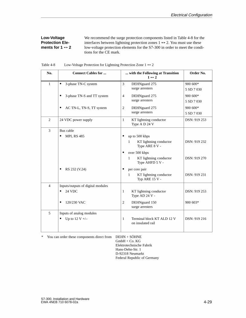
4-29S7-300, Installation and HardwareEWA 4NEB 710 6078-02a
We recommend the surge protection components listed in Table 4-8 for theinterfaces between lightning protection zones 1 2. You must use theselow-voltage protection elements for the S7-300 in order to meet the condi-tions for the CE mark.
Table 4-8 Low-Voltage Protection for Lightning Protection Zone 1 2
No. Connect Cables for ... ... with the Following at Transition1 2
Order No.
1 3-phase TN-C system 3 DEHNguard 275surge arresters
900 600*
5 SD 7 030
3-phase TN-S and TT system 4 DEHNguard 275surge arresters
900 600*
5 SD 7 030
AC TN-L, TN-S, TT system 2 DEHNguard 275surge arresters
900 600*
5 SD 7 030
2 24 VDC power supply 1 KT lightning conductor Type A D 24 V
DSN: 919 253
3 Bus cable
MPI, RS 485 up to 500 kbps
1 KT lightning conductorType ARE 8 V -
DSN: 919 232
over 500 kbps
1 KT lightning conductorType AHFD 5 V -
DSN: 919 270
RS 232 (V.24) per core pair
1 KT lightning conductorTyp ARE 15 V -
DSN: 919 231
4 Inputs/outputs of digital modules
24 VDC 1 KT lightning conductorType AD 24 V -
DSN: 919 253
120/230 VAC 2 DEHNguard 150surge arresters
900 603*
5 Inputs of analog modules
Up to 12 V +/– 1 Terminal block KT ALD 12 V on insulated rail
DSN: 919 216
* You can order these components direct from DEHN + SÖHNEGmbH + Co. KGElektrotechnische FabrikHans-Dehn-Str. 1D-92318 NeumarktFederal Republic of Germany
Low-VoltageProtection Ele-ments for 1 2
Electrical Configuration
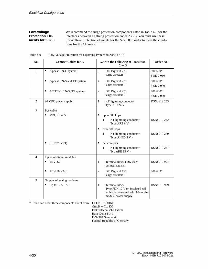
4-30S7-300, Installation and Hardware
EWA 4NEB 710 6078-02a
We recommend the surge protection components listed in Table 4-9 for theinterfaces between lightning protection zones 2 3. You must use theselow-voltage protection elements for the S7-300 in order to meet the condi-tions for the CE mark.
Table 4-9 Low-Voltage Protection for Lightning Protection Zone 2 3
No. Connect Cables for ... ... with the Following at Transition2 3
Order No.
1 3-phase TN-C system 3 DEHNguard 275surge arresters
900 600*
5 SD 7 030
3-phase TN-S and TT system 4 DEHNguard 275surge arresters
900 600*
5 SD 7 030
AC TN-L, TN-S, TT system 2 DEHNguard 275surge arresters
900 600*
5 SD 7 030
2 24 VDC power supply 1 KT lightning conductor Type A D 24 V
DSN: 919 253
3 Bus cable
MPI, RS 485 up to 500 kbps
1 KT lightning conductorType ARE 8 V -
DSN: 919 232
over 500 kbps
1 KT lightning conductorType AHFD 5 V -
DSN: 919 270
RS 232 (V.24) per core pair
1 KT lightning conductorTyp ARE 15 V -
DSN: 919 231
4 Inputs of digital modules
24 VDC 1 Terminal block FDK 60 V on insulated rail
DSN: 919 997
120/230 VAC 2 DEHNguard 150surge arresters
900 603*
5 Outputs of analog modules
Up to 12 V +/– 1 Terminal blockType FDK 12 V on insulated rail which is connected with M– of themodule power supply.
DSN: 919 999
* You can order these components direct from DEHN + SÖHNEGmbH + Co. KGElektrotechnische FabrikHans-Dehn-Str. 1D-92318 NeumarktFederal Republic of Germany
Low-VoltageProtection Ele-ments for 2 3
Electrical Configuration
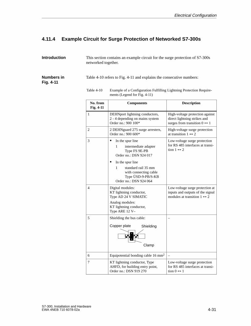
4-31S7-300, Installation and HardwareEWA 4NEB 710 6078-02a
4.11.4 Example Circuit for Surge Protection of Networked S7-300s
This section contains an example circuit for the surge protection of S7-300snetworked together.
Table 4-10 refers to Fig. 4-11 and explains the consecutive numbers:
Table 4-10 Example of a Configuration Fulfilling Lightning Protection Require-ments (Legend for Fig. 4-11)
No. fromFig. 4-11
Components Description
1 DEHNport lightning conductors,2 - 4 depending on mains systemOrder no.: 900 100*
High-voltage protection againstdirect lightning strikes andsurges from transition 0 1
2 2 DEHNguard 275 surge arresters,Order no.: 900 600*
High-voltage surge protectionat transition 1 2
3 In the spur line
1 intermediate adapterType FS 9E-PB
Order no.: DSN 924 017
Low-voltage surge protectionfor RS 485 interfaces at transi-tion 1 2
In the spur line
1 standard rail 35 mmwith connecting cableType ÜSD-9-PB/S-KB
Order no.: DSN 924 064
4 Digital modules:KT lightning conductor,Type AD 24 V SIMATIC
Analog modules:KT lightning conductor,Type ARE 12 V–
Low-voltage surge protection atinputs and outputs of the signalmodules at transition 1 2
5 Shielding the bus cable:
ÎÎÎ
Copper plate Shielding
Clamp
–
6 Equipotential bonding cable 16 mm2 –
7 KT lightning conductor, TypeAHFD, for building entry point,Order no.: DSN 919 270
Low-voltage surge protectionfor RS 485 interfaces at transi-tion 0 1
Introduction
Numbers inFig. 4-11
Electrical Configuration
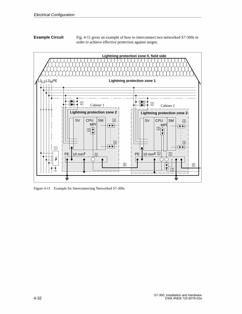
4-32S7-300, Installation and Hardware
EWA 4NEB 710 6078-02a
Fig. 4-11 gives an example of how to interconnect two networked S7-300s inorder to achieve effective protection against surges:
CPUSV
10 mm2PE
Cabinet 1
L1L2L3NPE
Lightning protection zone 0, field side
Lightning protection zone 1
Lightning protection zone 2
SMMPI
CPUSV
10 mm2PE
Cabinet 2
SM
MPI
Lightning protection zone 2
Figure 4-11 Example for Interconnecting Networked S7-300s
Example Circuit
Electrical Configuration
5-1S7-300, Installation and HardwareEWA 4NEB 710 6078-02a
Installing an S7-300
You have chosen the configuration for your S7-300 (see Chapter 2).
In this chapter we show you how to prepare and install the components of theS7-300 system.
This chapter contains the following sections describing how to install anS7-300:
Section Contents Page
5.1 Installing the Rail 5-2
5.2 Module Accessories 5-5
5.3 Installing the Modules on the Rail 5-6
5.4 Identifying the Modules with the Slot Numbers 5-9
Introduction
In this Chapter
5
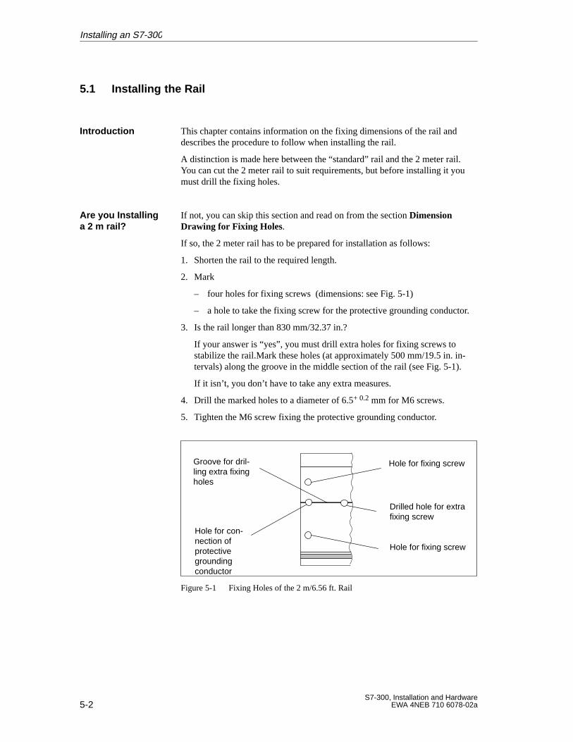
5-2S7-300, Installation and Hardware
EWA 4NEB 710 6078-02a
5.1 Installing the Rail
This chapter contains information on the fixing dimensions of the rail anddescribes the procedure to follow when installing the rail.
A distinction is made here between the “standard” rail and the 2 meter rail.You can cut the 2 meter rail to suit requirements, but before installing it youmust drill the fixing holes.
If not, you can skip this section and read on from the section DimensionDrawing for Fixing Holes.
If so, the 2 meter rail has to be prepared for installation as follows:
1. Shorten the rail to the required length.
2. Mark
– four holes for fixing screws (dimensions: see Fig. 5-1)
– a hole to take the fixing screw for the protective grounding conductor.
3. Is the rail longer than 830 mm/32.37 in.?
If your answer is “yes”, you must drill extra holes for fixing screws tostabilize the rail.Mark these holes (at approximately 500 mm/19.5 in. in-tervals) along the groove in the middle section of the rail (see Fig. 5-1).
If it isn’ t, you don’t have to take any extra measures.
4. Drill the marked holes to a diameter of 6.5+ 0.2 mm for M6 screws.
5. Tighten the M6 screw fixing the protective grounding conductor.
Groove for dril-ling extra fixingholes
Hole for con-nection ofprotectivegroundingconductor
Hole for fixing screw
Drilled hole for extrafixing screw
Hole for fixing screw
Figure 5-1 Fixing Holes of the 2 m/6.56 ft. Rail
Introduction
Are you Installinga 2 m rail?
Installing an S7-300
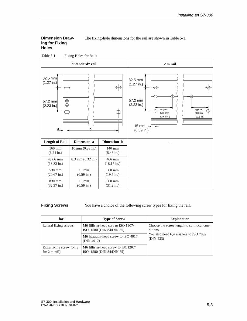
5-3S7-300, Installation and HardwareEWA 4NEB 710 6078-02a
The fixing-hole dimensions for the rail are shown in Table 5-1.
Table 5-1 Fixing Holes for Rails
“Standard” rail 2 m rail
32.5 mm(1.27 in.)
57.2 mm(2.23 in.)
a b
32.5 mm(1.27 in.)
57.2 mm(2.23 in.)
15 mm(0.59 in.)
approx.
500 mm
(19.5 in.)
approx.
500 mm
(19.5 in.)
Length of Rail Dimension a Dimension b –
160 mm(6.24 in.)
10 mm (0.39 in.) 140 mm(5.46 in.)
482.6 mm(18.82 in.)
8.3 mm (0.32 in.) 466 mm(18.17 in.)
530 mm(20.67 in.)
15 mm(0.59 in.)
500 mm(19.5 in.)
830 mm(32.37 in.)
15 mm(0.59 in.)
800 mm(31.2 in.)
You have a choice of the following screw types for fixing the rail.
for Type of Screw Explanation
Lateral fixing screws M6 fillister-head scre to ISO 1207/ISO 1580 (DIN 84/DIN 85)
Choose the screw length to suit local con-ditions.Y l d 6 4 h t ISO 7092
M6 hexagon-head screw to ISO 4017(DIN 4017)
You also need 6,4 washers to ISO 7092(DIN 433)
Extra fixing screw (onlyfor 2 m rail)
M6 fillister-head screw to ISO1207/ISO 1580 (DIN 84/DIN 85)
Dimension Draw-ing for FixingHoles
Fixing Screws
Installing an S7-300
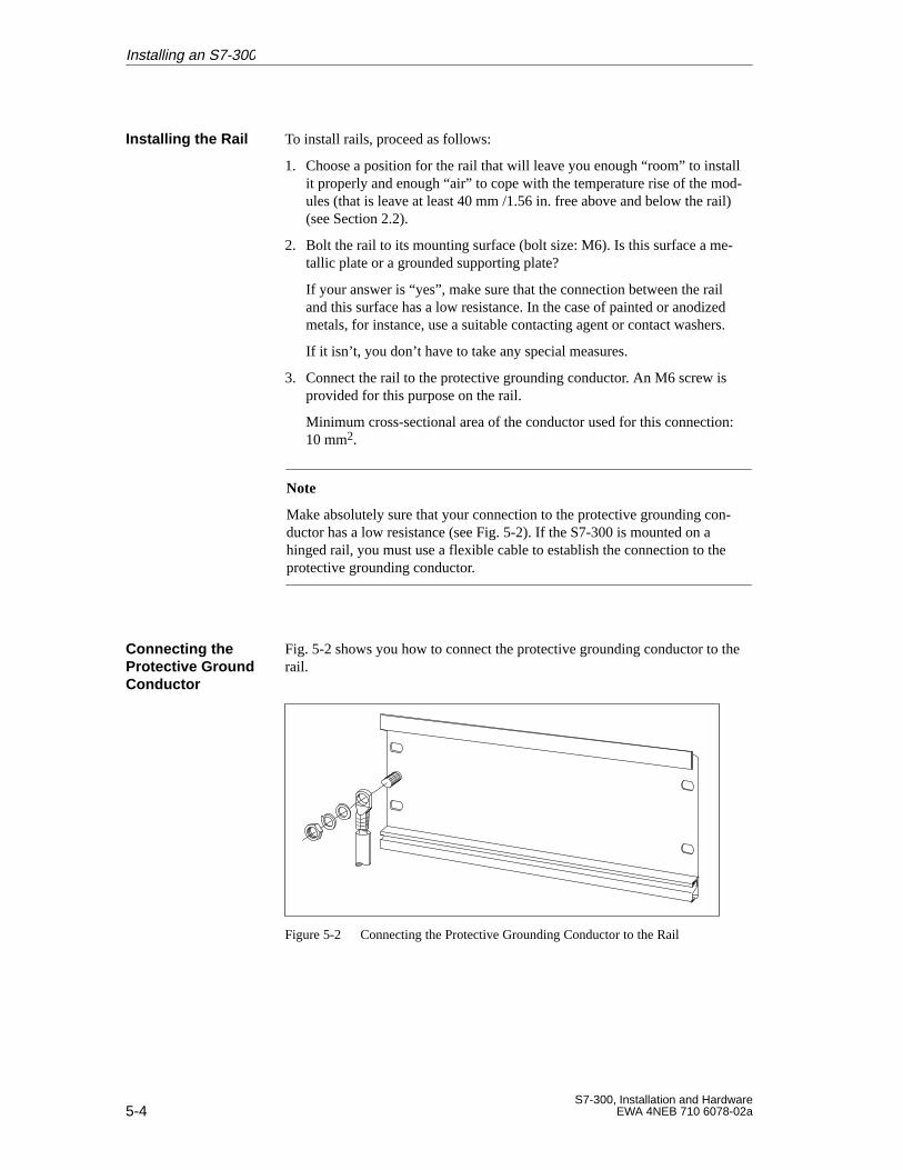
5-4S7-300, Installation and Hardware
EWA 4NEB 710 6078-02a
To install rails, proceed as follows:
1. Choose a position for the rail that will leave you enough “room” to installit properly and enough “air” to cope with the temperature rise of the mod-ules (that is leave at least 40 mm /1.56 in. free above and below the rail)(see Section 2.2).
2. Bolt the rail to its mounting surface (bolt size: M6). Is this surface a me-tallic plate or a grounded supporting plate?
If your answer is “yes”, make sure that the connection between the railand this surface has a low resistance. In the case of painted or anodizedmetals, for instance, use a suitable contacting agent or contact washers.
If it isn’ t, you don’t have to take any special measures.
3. Connect the rail to the protective grounding conductor. An M6 screw isprovided for this purpose on the rail.
Minimum cross-sectional area of the conductor used for this connection:10 mm2.
Note
Make absolutely sure that your connection to the protective grounding con-ductor has a low resistance (see Fig. 5-2). If the S7-300 is mounted on ahinged rail, you must use a flexible cable to establish the connection to theprotective grounding conductor.
Fig. 5-2 shows you how to connect the protective grounding conductor to therail.
Figure 5-2 Connecting the Protective Grounding Conductor to the Rail
Installing the Rail
Connecting theProtective GroundConductor
Installing an S7-300
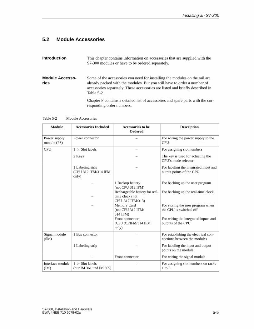
5-5S7-300, Installation and HardwareEWA 4NEB 710 6078-02a
5.2 Module Accessories
This chapter contains information on accessories that are supplied with theS7-300 modules or have to be ordered separately.
Some of the accessories you need for installing the modules on the rail arealready packed with the modules. But you still have to order a number ofaccessories separately. These accessories are listed and briefly described inTable 5-2.
Chapter F contains a detailed list of accessories and spare parts with the cor-responding order numbers.
Table 5-2 Module Accessories
Module Accessories Included Accessories to be Ordered
Description
Power supplymodule (PS)
Power connector – For wiring the power supply to theCPU
CPU 1 Slot labels – For assigning slot numbers
2 Keys – The key is used for actuating theCPU’s mode selector
1 Labeling strip(CPU 312 IFM/314 IFMonly)
– For labeling the integrated input andoutput points of the CPU
–
–
–
1 Backup battery(not CPU 312 IFM)Rechargeable battery for real-time clock (notCPU 312 IFM/313)Memory Card(not CPU 312 IFM/314 IFM)Front connector(CPU 312IFM/314 IFMonly)
For backing up the user program
For backing up the real-time clock
For storing the user program whenthe CPU is switched off For wiring the integrated inputs andoutputs of the CPU
Signal module(SM)
1 Bus connector – For establishing the electrical con-nections between the modules( )
1 Labeling strip – For labeling the input and outputpoints on the module
– Front connector For wiring the signal module
Interface module(IM)
1 Slot labels(nur IM 361 und IM 365)
– For assigning slot numbers on racks1 to 3
Introduction
Module Accesso -ries
Installing an S7-300
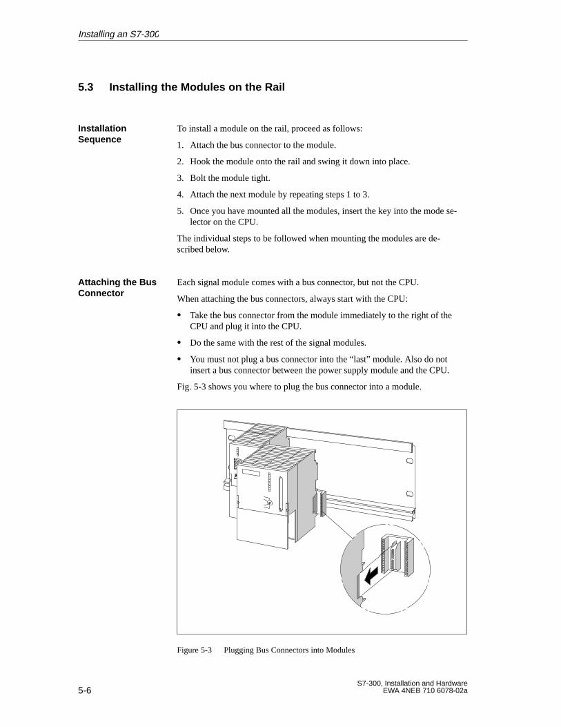
5-6S7-300, Installation and Hardware
EWA 4NEB 710 6078-02a
5.3 Installing the Modules on the Rail
To install a module on the rail, proceed as follows:
1. Attach the bus connector to the module.
2. Hook the module onto the rail and swing it down into place.
3. Bolt the module tight.
4. Attach the next module by repeating steps 1 to 3.
5. Once you have mounted all the modules, insert the key into the mode se-lector on the CPU.
The individual steps to be followed when mounting the modules are de-scribed below.
Each signal module comes with a bus connector, but not the CPU.
When attaching the bus connectors, always start with the CPU:
Take the bus connector from the module immediately to the right of theCPU and plug it into the CPU.
Do the same with the rest of the signal modules.
You must not plug a bus connector into the “last” module. Also do notinsert a bus connector between the power supply module and the CPU.
Fig. 5-3 shows you where to plug the bus connector into a module.
Figure 5-3 Plugging Bus Connectors into Modules
Installation Sequence
Attaching the BusConnector
Installing an S7-300
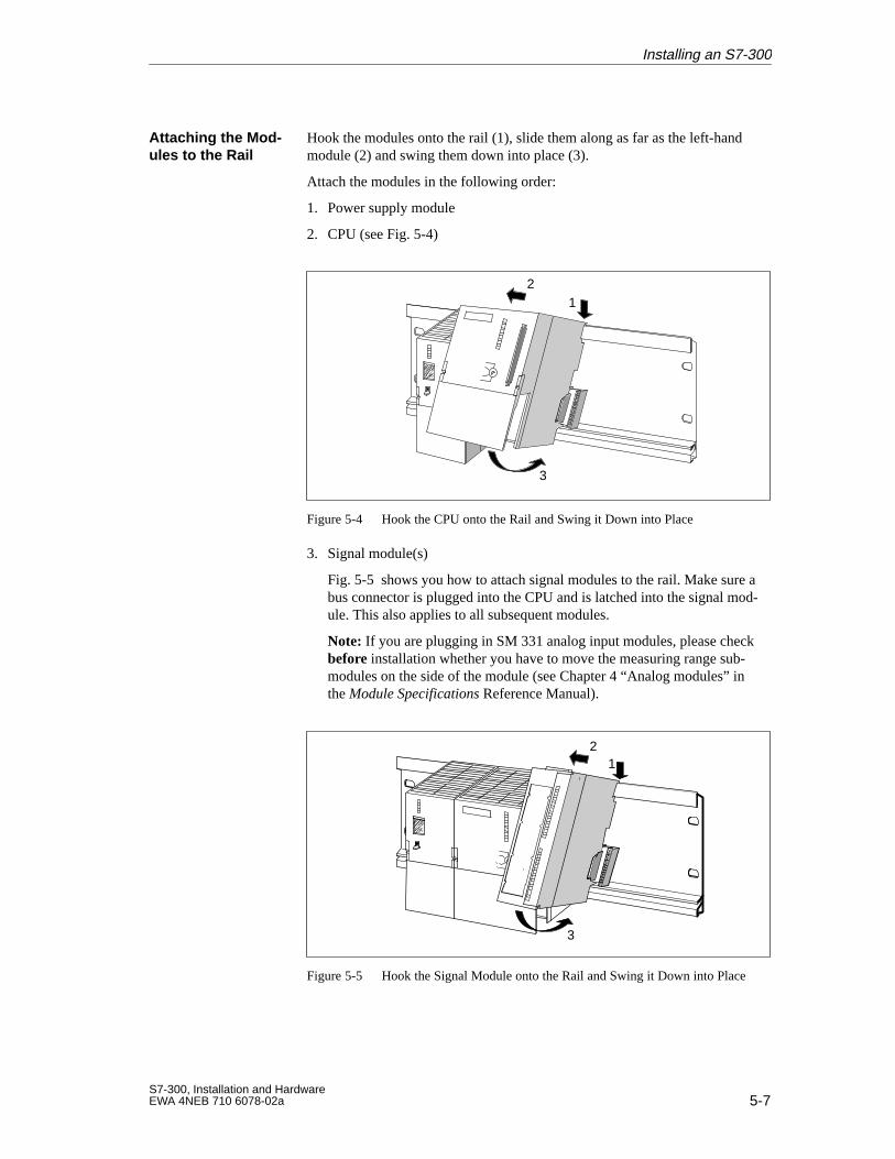
5-7S7-300, Installation and HardwareEWA 4NEB 710 6078-02a
Hook the modules onto the rail (1), slide them along as far as the left-handmodule (2) and swing them down into place (3).
Attach the modules in the following order:
1. Power supply module
2. CPU (see Fig. 5-4)
1
3
2
Figure 5-4 Hook the CPU onto the Rail and Swing it Down into Place
3. Signal module(s)
Fig. 5-5 shows you how to attach signal modules to the rail. Make sure abus connector is plugged into the CPU and is latched into the signal mod-ule. This also applies to all subsequent modules.
Note: If you are plugging in SM 331 analog input modules, please checkbefore installation whether you have to move the measuring range sub-modules on the side of the module (see Chapter 4 “Analog modules” inthe Module Specifications Reference Manual).
1
3
2
Figure 5-5 Hook the Signal Module onto the Rail and Swing it Down into Place
Attaching the Mod-ules to the Rail
Installing an S7-300
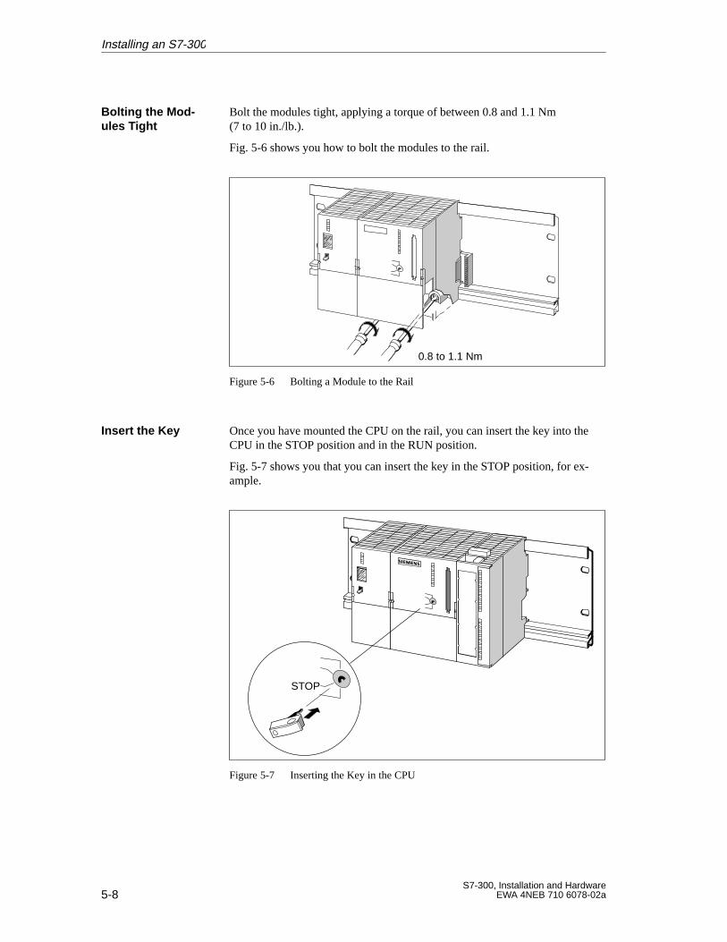
5-8S7-300, Installation and Hardware
EWA 4NEB 710 6078-02a
Bolt the modules tight, applying a torque of between 0.8 and 1.1 Nm(7 to 10 in./lb.).
Fig. 5-6 shows you how to bolt the modules to the rail.
0.8 to 1.1 Nm
Figure 5-6 Bolting a Module to the Rail
Once you have mounted the CPU on the rail, you can insert the key into theCPU in the STOP position and in the RUN position.
Fig. 5-7 shows you that you can insert the key in the STOP position, for ex-ample.
STOP
Figure 5-7 Inserting the Key in the CPU
Bolting the Mod-ules Tight
Insert the Key
Installing an S7-300
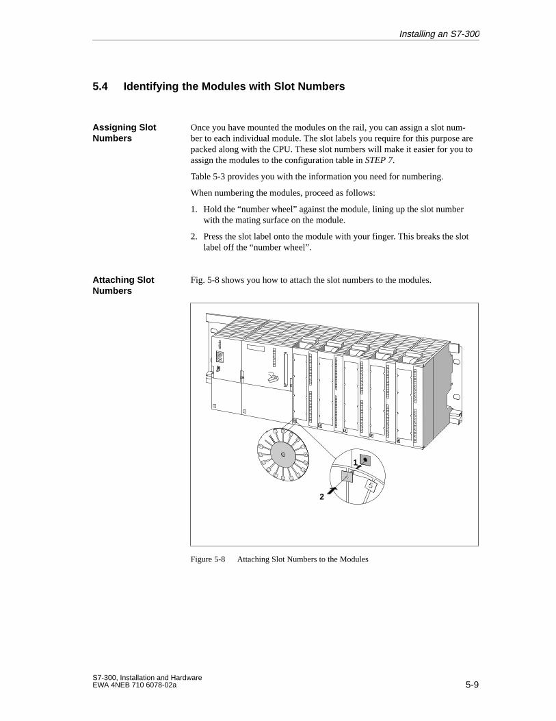
5-9S7-300, Installation and HardwareEWA 4NEB 710 6078-02a
5.4 Identifying the Modules with Slot Numbers
Once you have mounted the modules on the rail, you can assign a slot num-ber to each individual module. The slot labels you require for this purpose arepacked along with the CPU. These slot numbers will make it easier for you toassign the modules to the configuration table in STEP 7.
Table 5-3 provides you with the information you need for numbering.
When numbering the modules, proceed as follows:
1. Hold the “number wheel” against the module, lining up the slot numberwith the mating surface on the module.
2. Press the slot label onto the module with your finger. This breaks the slotlabel off the “number wheel”.
Fig. 5-8 shows you how to attach the slot numbers to the modules.
1
2
Figure 5-8 Attaching Slot Numbers to the Modules
Assigning SlotNumbers
Attaching SlotNumbers
Installing an S7-300
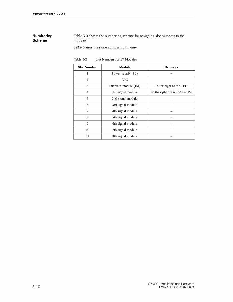
5-10S7-300, Installation and Hardware
EWA 4NEB 710 6078-02a
Table 5-3 shows the numbering scheme for assigning slot numbers to themodules.
STEP 7 uses the same numbering scheme.
Table 5-3 Slot Numbers for S7 Modules
Slot Number Module Remarks
1 Power supply (PS) –
2 CPU –
3 Interface module (IM) To the right of the CPU
4 1st signal module To the right of the CPU or IM
5 2nd signal module –
6 3rd signal module –
7 4th signal module –
8 5th signal module –
9 6th signal module –
10 7th signal module –
11 8th signal module –
NumberingScheme
Installing an S7-300
6-1S7-300, Installation and HardwareEWA 4NEB 710 6078-02a
Wiring an S7-300
You have mounted the S7-300 completely (see Chapter 5).
In this chapter we show you how to wire the modules of the S7-300.
The following sections describe the wiring:
Section Contents Page
6.1 Wiring Rules 6-2
6.2 Wiring the Power Supply Module and CPU 6-3
6.3 Setting the Power Supply Voltage Selector Switch 6-5
6.4 Wiring the Front Connectors of the Signal Modules 6-6
6.5 Connecting Shielded Cables Using the Shield ConnectionElement
6-10
Introduction
In this Chapter
6
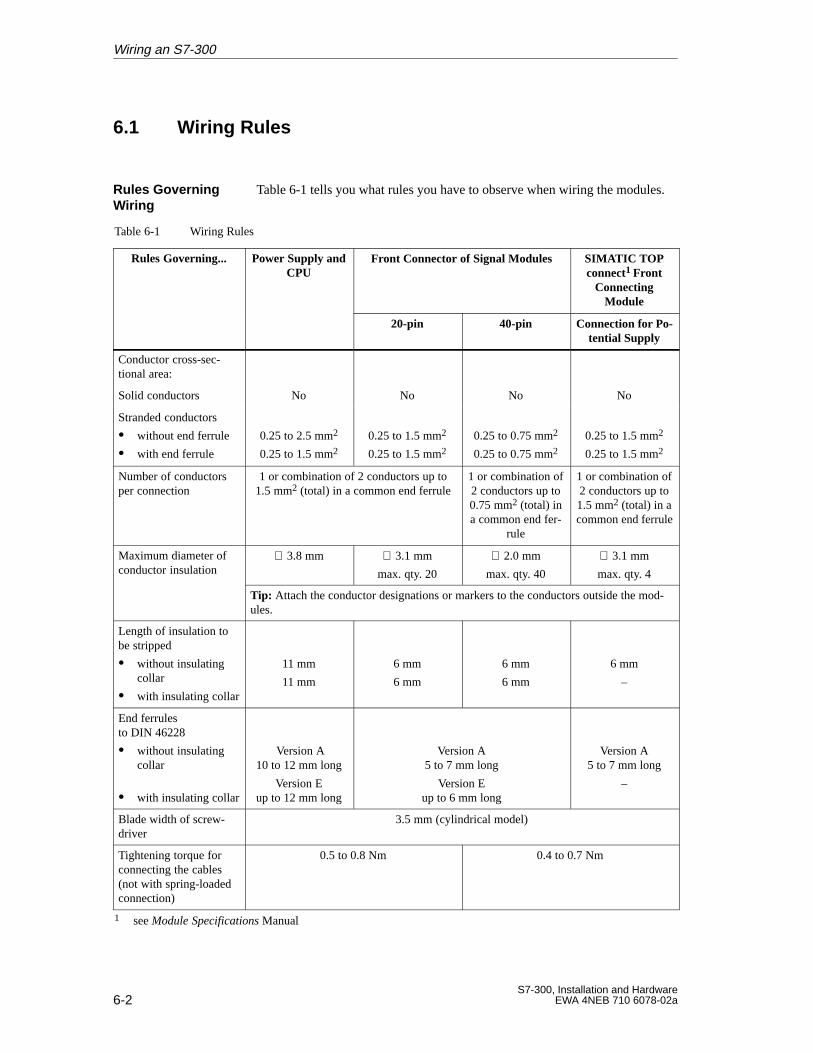
6-2S7-300, Installation and Hardware
EWA 4NEB 710 6078-02a
6.1 Wiring Rules
Table 6-1 tells you what rules you have to observe when wiring the modules.
Table 6-1 Wiring Rules
Rules Governing... Power Supply andCPU
Front Connector of Signal Modules SIMATIC TOPconnect1 Front
ConnectingModule
20-pin 40-pin Connection for Po-tential Supply
Conductor cross-sec-tional area:
Solid conductors No No No No
Stranded conductors
without end ferrule
with end ferrule
0.25 to 2.5 mm2
0.25 to 1.5 mm20.25 to 1.5 mm2
0.25 to 1.5 mm20.25 to 0.75 mm2
0.25 to 0.75 mm20.25 to 1.5 mm2
0.25 to 1.5 mm2
Number of conductorsper connection
1 or combination of 2 conductors up to1.5 mm2 (total) in a common end ferrule
1 or combination of2 conductors up to0.75 mm2 (total) ina common end fer-
rule
1 or combination of2 conductors up to1.5 mm2 (total) in acommon end ferrule
Maximum diameter ofconductor insulation
∅ 3.8 mm ∅ 3.1 mm
max. qty. 20
∅ 2.0 mm
max. qty. 40
∅ 3.1 mm
max. qty. 4
Tip: Attach the conductor designations or markers to the conductors outside the mod-ules.
Length of insulation tobe stripped
without insulatingcollar
with insulating collar
11 mm
11 mm
6 mm
6 mm
6 mm
6 mm
6 mm
–
End ferrulesto DIN 46228
without insulatingcollar
with insulating collar
Version A10 to 12 mm long
Version Eup to 12 mm long
Version A5 to 7 mm long
Version Eup to 6 mm long
Version A5 to 7 mm long
–
Blade width of screw-driver
3.5 mm (cylindrical model)
Tightening torque forconnecting the cables(not with spring-loadedconnection)
0.5 to 0.8 Nm 0.4 to 0.7 Nm
1 see Module Specifications Manual
Rules GoverningWiring
Wiring an S7-300
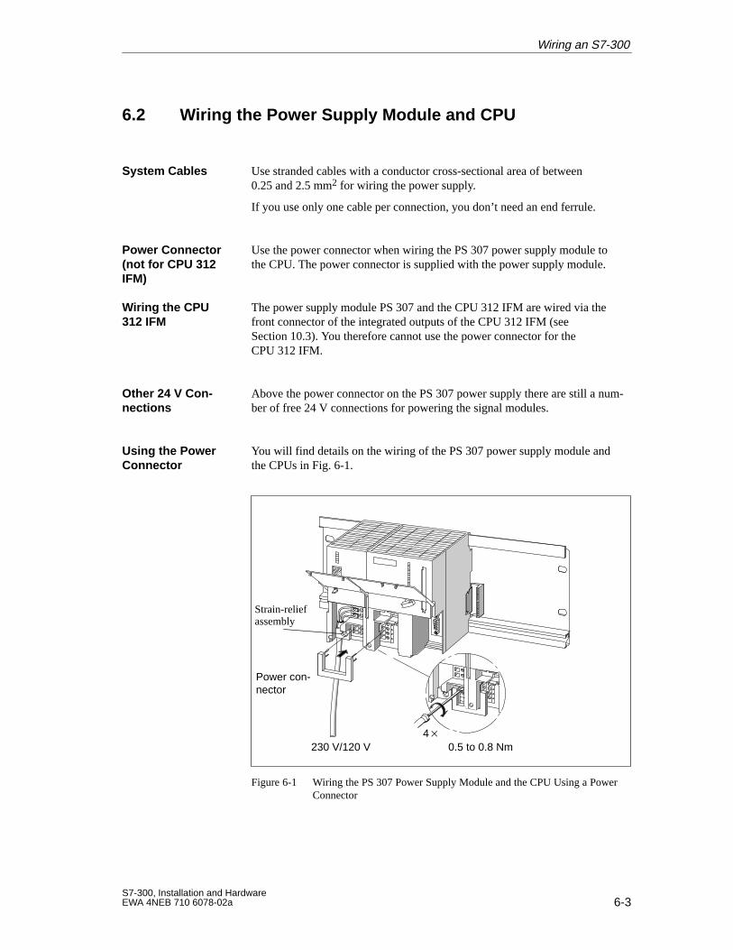
6-3S7-300, Installation and HardwareEWA 4NEB 710 6078-02a
6.2 Wiring the Power Supply Module and CPU
Use stranded cables with a conductor cross-sectional area of between0.25 and 2.5 mm2 for wiring the power supply.
If you use only one cable per connection, you don’t need an end ferrule.
Use the power connector when wiring the PS 307 power supply module tothe CPU. The power connector is supplied with the power supply module.
The power supply module PS 307 and the CPU 312 IFM are wired via thefront connector of the integrated outputs of the CPU 312 IFM (seeSection 10.3). You therefore cannot use the power connector for theCPU 312 IFM.
Above the power connector on the PS 307 power supply there are still a num-ber of free 24 V connections for powering the signal modules.
You will find details on the wiring of the PS 307 power supply module andthe CPUs in Fig. 6-1.
0.5 to 0.8 Nm
Power con-nector
230 V/120 V
Strain-relief assembly
4
Figure 6-1 Wiring the PS 307 Power Supply Module and the CPU Using a PowerConnector
System Cables
Power Connector(not for CPU 312IFM)
Wiring the CPU312 IFM
Other 24 V Con -nections
Using the PowerConnector
Wiring an S7-300
6-4S7-300, Installation and Hardware
EWA 4NEB 710 6078-02a
Proceed as follows when wiring the power supply module and CPU (seeFig. 6-1).
!Warning
Accidental contact with live conductors is possible, if the power supplymodule and any additional load power supplies are switched on.
Make sure the S7-300 is absolutely dead before doing any wiring!
1. Open the front doors of the PS 307 power supply and CPU.
2. Undo the strain-relief assembly on the PS 307.
3. Strip the insulation off the power cable (230V/120V) and connect it to thePS 307.
4. Screw the strain-relief assembly tight.
5. CPU 312 IFM: Strip the insulation off the power cable of theCPU 312 IFM and connect it to the PS 307.
CPU 313/314/314 IFM/315/315-2 DP/316: Plug in the power connectorand screw it tight.
6. Close the front doors.
Use a torque of between 0.5 and 0.8 Nm when tightening the terminalscrews.
Wiring
Tightening Torque
Wiring an S7-300

6-5S7-300, Installation and HardwareEWA 4NEB 710 6078-02a
6.3 Setting the Power Supply Voltage Selector Switch
Check to see that the voltage selector switch on the power supply module isset to your local system voltage. This switch is always factory-set to 230 V.To select another system voltage, do the following:
1. Pry the cover off with a screwdriver.
2. Set the selector to your system voltage.
3. Replace the cover.
Fig. 6-2 shows you how to set the voltage selector switch.
1
2
Figure 6-2 Voltage Selector Switch on the PS 307
Setting the VoltageSelector Switch
Wiring an S7-300
6-6S7-300, Installation and Hardware
EWA 4NEB 710 6078-02a
6.4 Wiring the Front Connectors of the Signal Modules
You can use cables with stranded conductors, for cross sections see Table 6-1.
You do not need end ferrules. However, if you prefer to use end ferrules, useonly the ferrules listed in Table 6-1.
You wire the integrated inputs/outputs of the CPU 312 IFM and 314 IFM alsovia the front connector as described in this section.
If you use the possible digital inputs of the CPUs for the special functions,you wire these inputs with shielded cables via a shield connecting element(see Section 6.5). This also applies for wiring the analog inputs/outputs of theCPU 314 IFM.
The 20-pin and 40–pin front connectors are available in two designs: withspring-loaded terminals and screw terminals.
The front connector with spring-loaded terminals is wired quite simply: Insertthe screw-driver vertically into the opening with the red opening mechanism,insert the wire into the associated terminal and remove the screw-driver.
Tip: There is a separate opening for test probes up to 2 mm in diameter to theleft of the opening for the screw-driver.
Wire the screw-type front connector as follows:
1. Prepare the connector for wiring.
2. Wire the connector.
3. Prepare the module for operation.
These three steps are described on the following pages.
Cables
Integrated Inputs/Outputs
Types of FrontConnector
Spring-LoadedTerminals
Wiring the FrontConnector
Wiring an S7-300
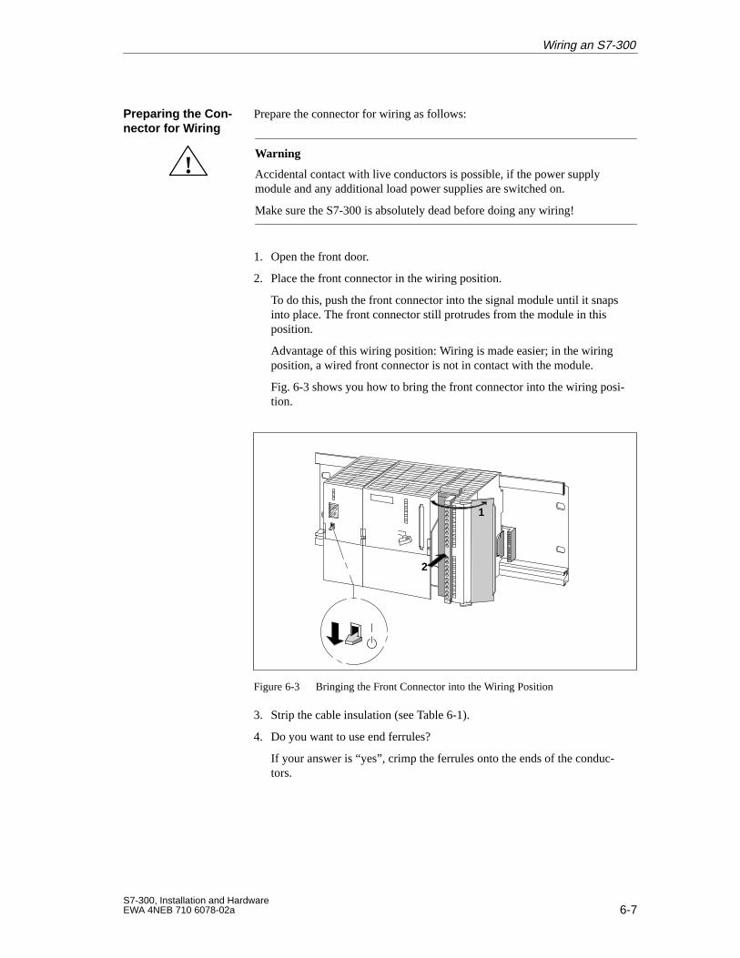
6-7S7-300, Installation and HardwareEWA 4NEB 710 6078-02a
Prepare the connector for wiring as follows:
!Warning
Accidental contact with live conductors is possible, if the power supplymodule and any additional load power supplies are switched on.
Make sure the S7-300 is absolutely dead before doing any wiring!
1. Open the front door.
2. Place the front connector in the wiring position.
To do this, push the front connector into the signal module until it snapsinto place. The front connector still protrudes from the module in thisposition.
Advantage of this wiring position: Wiring is made easier; in the wiringposition, a wired front connector is not in contact with the module.
Fig. 6-3 shows you how to bring the front connector into the wiring posi-tion.
2
1
Figure 6-3 Bringing the Front Connector into the Wiring Position
3. Strip the cable insulation (see Table 6-1).
4. Do you want to use end ferrules?
If your answer is “yes”, crimp the ferrules onto the ends of the conduc-tors.
Preparing the Con-nector for W iring
Wiring an S7-300
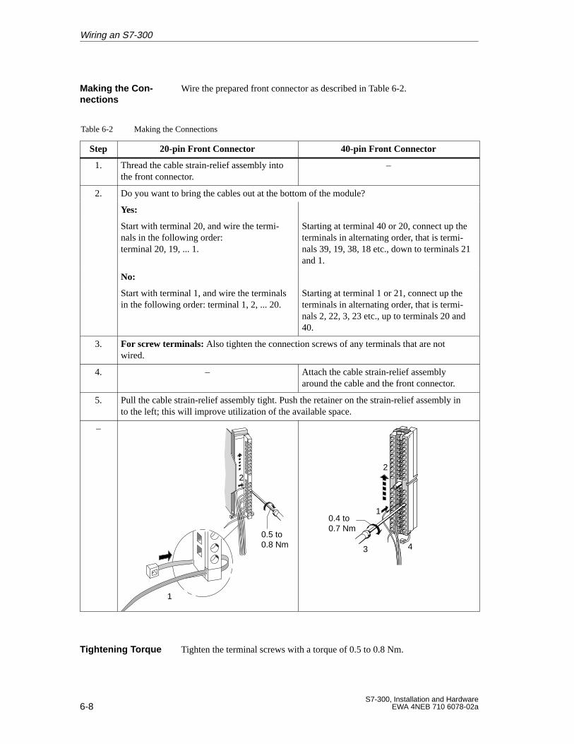
6-8S7-300, Installation and Hardware
EWA 4NEB 710 6078-02a
Wire the prepared front connector as described in Table 6-2.
Table 6-2 Making the Connections
Step 20-pin Front Connector 40-pin Front Connector
1. Thread the cable strain-relief assembly intothe front connector.
–
2. Do you want to bring the cables out at the bottom of the module?
Yes:
Start with terminal 20, and wire the termi-nals in the following order: terminal 20, 19, ... 1.
Starting at terminal 40 or 20, connect up theterminals in alternating order, that is termi-nals 39, 19, 38, 18 etc., down to terminals 21and 1.
No:
Start with terminal 1, and wire the terminalsin the following order: terminal 1, 2, ... 20.
Starting at terminal 1 or 21, connect up theterminals in alternating order, that is termi-nals 2, 22, 3, 23 etc., up to terminals 20 and40.
3. For screw terminals: Also tighten the connection screws of any terminals that are notwired.
4. – Attach the cable strain-relief assemblyaround the cable and the front connector.
5. Pull the cable strain-relief assembly tight. Push the retainer on the strain-relief assembly into the left; this will improve utilization of the available space.
–
1
2
0.5 to0.8 Nm
1
2
43
0.4 to0.7 Nm
Tighten the terminal screws with a torque of 0.5 to 0.8 Nm.
Making the Con-nections
Tightening Torque
Wiring an S7-300
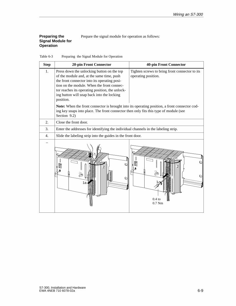
6-9S7-300, Installation and HardwareEWA 4NEB 710 6078-02a
Prepare the signal module for operation as follows:
Table 6-3 Preparing the Signal Module for Operation
Step 20-pin Front Connector 40-pin Front Connector
1. Press down the unlocking button on the topof the module and, at the same time, pushthe front connector into its operating posi-tion on the module. When the front connec-tor reaches its operating position, the unlock-ing button will snap back into the lockingposition.
Tighten screws to bring front connector to itsoperating position.
Note: When the front connector is brought into its operating position, a front connector cod-ing key snaps into place. The front connector then only fits this type of module (seeSection 9.2)
2. Close the front door.
3. Enter the addresses for identifying the individual channels in the labeling strip.
4. Slide the labeling strip into the guides in the front door.
–
1a
1
2
1
2
0.4 to0.7 Nm
Preparing the Signal Module forOperation
Wiring an S7-300
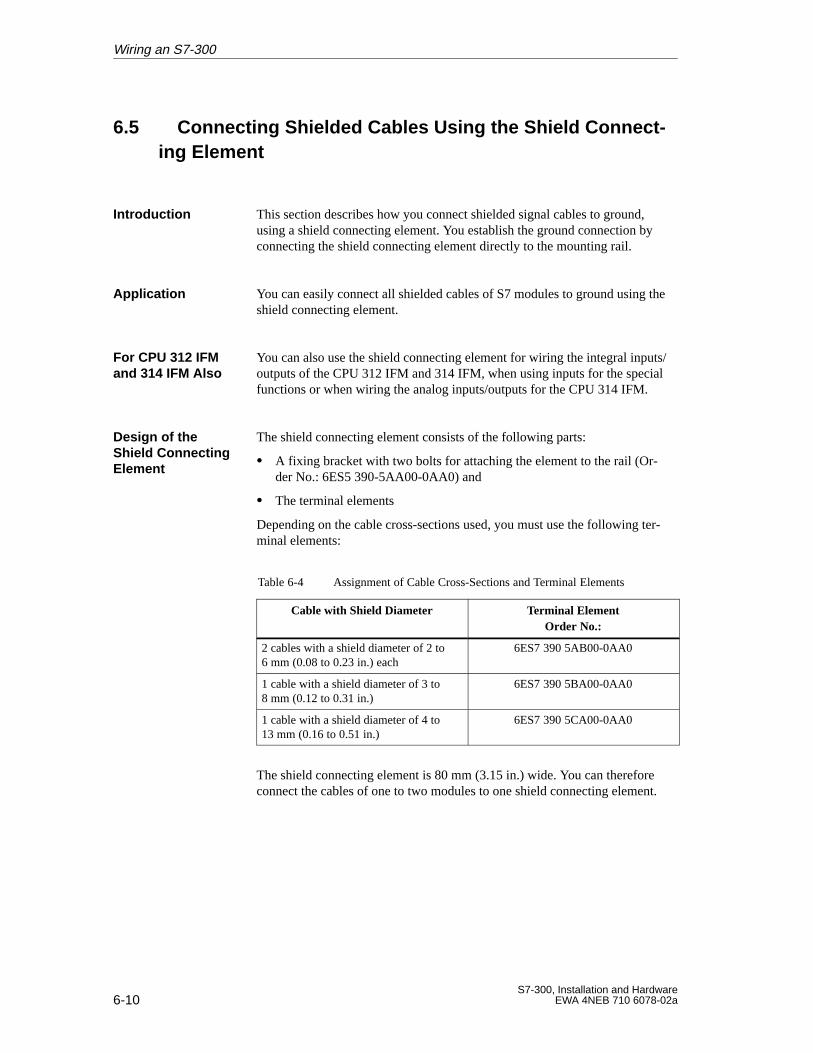
6-10S7-300, Installation and Hardware
EWA 4NEB 710 6078-02a
6.5 Connecting Shielded Cables Using the Shield Connect-ing Element
This section describes how you connect shielded signal cables to ground,using a shield connecting element. You establish the ground connection byconnecting the shield connecting element directly to the mounting rail.
You can easily connect all shielded cables of S7 modules to ground using theshield connecting element.
You can also use the shield connecting element for wiring the integral inputs/outputs of the CPU 312 IFM and 314 IFM, when using inputs for the specialfunctions or when wiring the analog inputs/outputs for the CPU 314 IFM.
The shield connecting element consists of the following parts:
A fixing bracket with two bolts for attaching the element to the rail (Or-der No.: 6ES5 390-5AA00-0AA0) and
The terminal elements
Depending on the cable cross-sections used, you must use the following ter-minal elements:
Table 6-4 Assignment of Cable Cross-Sections and Terminal Elements
Cable with Shield Diameter Terminal ElementOrder No.:
2 cables with a shield diameter of 2 to 6 mm (0.08 to 0.23 in.) each
6ES7 390 5AB00-0AA0
1 cable with a shield diameter of 3 to 8 mm (0.12 to 0.31 in.)
6ES7 390 5BA00-0AA0
1 cable with a shield diameter of 4 to 13 mm (0.16 to 0.51 in.)
6ES7 390 5CA00-0AA0
The shield connecting element is 80 mm (3.15 in.) wide. You can thereforeconnect the cables of one to two modules to one shield connecting element.
Introduction
Application
For CPU 312 IFMand 314 IFM Also
Design of theShield ConnectingElement
Wiring an S7-300
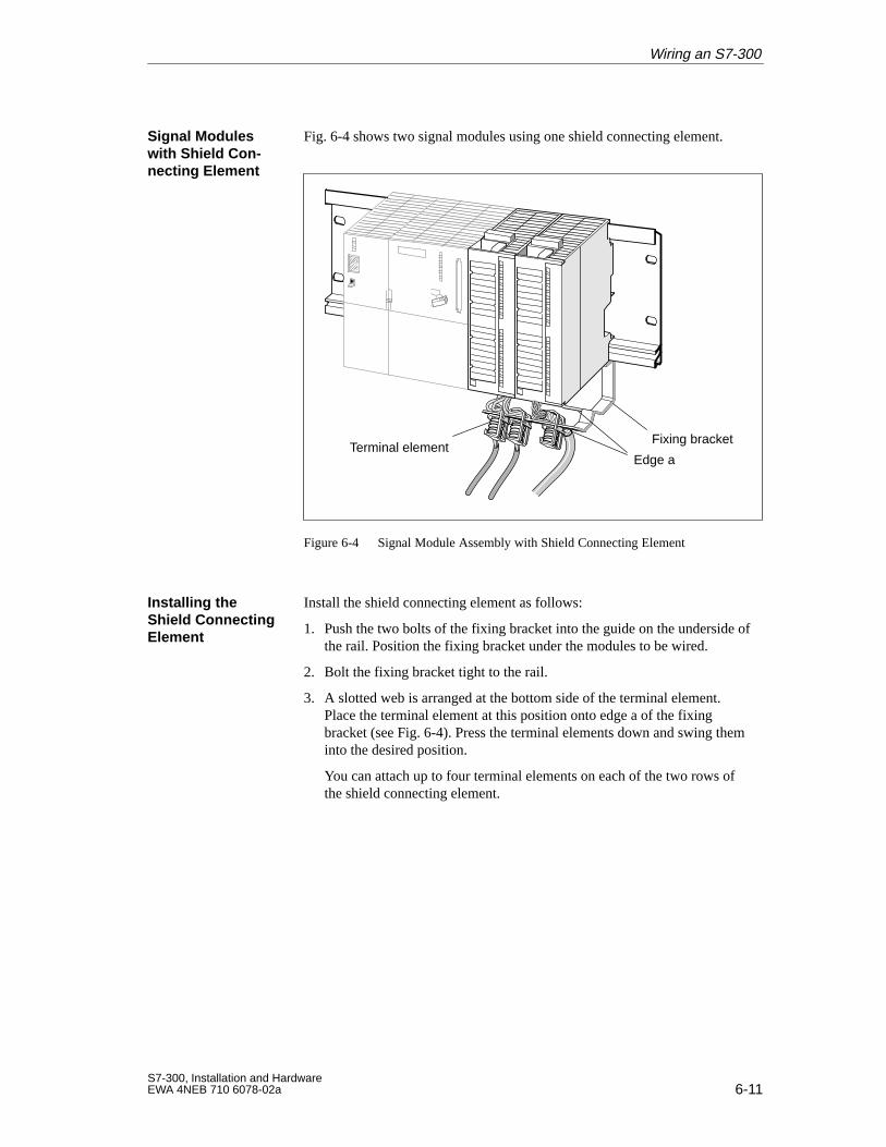
6-11S7-300, Installation and HardwareEWA 4NEB 710 6078-02a
Fig. 6-4 shows two signal modules using one shield connecting element.
Terminal elementFixing bracket
Edge a
Figure 6-4 Signal Module Assembly with Shield Connecting Element
Install the shield connecting element as follows:
1. Push the two bolts of the fixing bracket into the guide on the underside ofthe rail. Position the fixing bracket under the modules to be wired.
2. Bolt the fixing bracket tight to the rail.
3. A slotted web is arranged at the bottom side of the terminal element.Place the terminal element at this position onto edge a of the fixingbracket (see Fig. 6-4). Press the terminal elements down and swing theminto the desired position.
You can attach up to four terminal elements on each of the two rows ofthe shield connecting element.
Signal Moduleswith Shield Con -necting Element
Installing theShield ConnectingElement
Wiring an S7-300
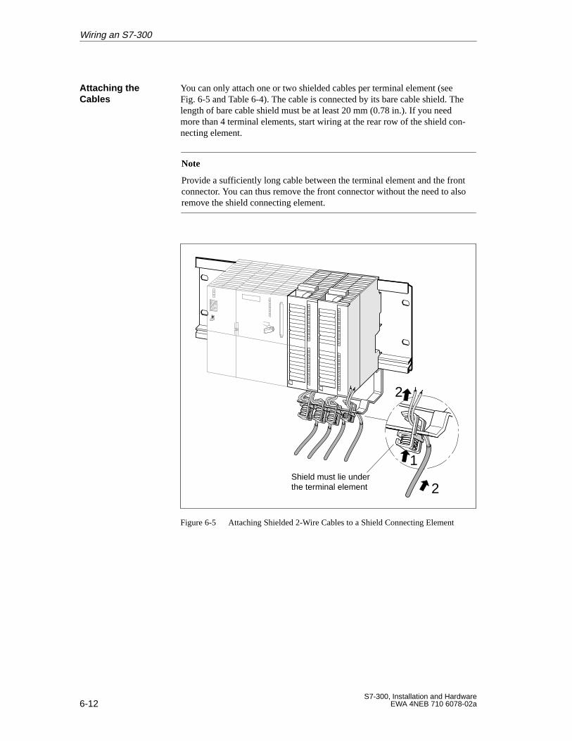
6-12S7-300, Installation and Hardware
EWA 4NEB 710 6078-02a
You can only attach one or two shielded cables per terminal element (seeFig. 6-5 and Table 6-4). The cable is connected by its bare cable shield. Thelength of bare cable shield must be at least 20 mm (0.78 in.). If you needmore than 4 terminal elements, start wiring at the rear row of the shield con-necting element.
Note
Provide a sufficiently long cable between the terminal element and the frontconnector. You can thus remove the front connector without the need to alsoremove the shield connecting element.
1
2
2
Shield must lie under the terminal element
Figure 6-5 Attaching Shielded 2-Wire Cables to a Shield Connecting Element
Attaching theCables
Wiring an S7-300
7-1S7-300, Installation and HardwareEWA 4NEB 710 6078-02a
Configuring an MPI or PROFIBUS Subnet
You can integrate the S7-300
in an MPI subnet via the MPI interface or
in a PROFIBUS subnet
– with a CPU 315-2 DP via the integrated PROFIBUS interface (seeChapter 11) or
– with a CP 342-5 DP.
The structure of an MPI subnet is basically the same as a PROFIBUS subnet.That means the same rules and the same components are used to set up thesubnet. The only exception arises if you set a baud rate > 1.5 Mbaud in aPROFIBUS subnet. In this case, you will need other components. Specialreference is made to these components where relevant in this documentation.
Since the structure of an MPI subnet does not differ from that of a PROFI-BUS subnet, general reference is made in the following sections to configur-ing a subnet.
You must assign MPI or PROFIBUS addresses to the individual nodes of anMPI or PROFIBUS subnet in order to enable them to communicate with eachother. How you assign these addresses and what rules you must observe isdescribed in the STEP 7 Manuals.
Chapter 11 (CPU 315–2 DP only) and Sections 10.4 and 10.7.8 contain allCPU-specific data you require for configuring communication.
The following sections in this chapter describe the configuration of an MPI orPROFIBUS subnet:
Section Contents Page
7.1 Configuring a Subnet 7-2
7.2 Network Components 7-18
Two Subnets
Same Structure
Configuring Com -munication
In this Chapter
7
7-2S7-300, Installation and Hardware
EWA 4NEB 710 6078-02a
7.1 Configuring a Subnet
The interface of the CPU for connecting, for example, programming devices,is called multipoint interface since several devices (that is, from severalpoints) can access the CPU via this interface. In other words: the CPU withthe multipoint interface can be networked without additional modules!
Digital, analog and intelligent modules of the programmable controller aswell as a wide range of field devices to EN 50170, part 3, such as drivers orvalve terminals, are installed in a distributed configuration in the direct vicin-ity of the process – across distances of up to 23 km (14.375 miles).
The modules and field devices are connected to the programmable controllervia the PROFIBUS-DP fieldbus and addressed in the same way as centralizedI/Os.
This chapter describes
The basic principles for configuring a subnet. It explains
– what a segment is
– the baud rates that are possible in a subnet, and
– special features of the MPI and PROFIBUS node addresses.
Rules for configuring a subnet. These rules are explained in examples ofpossible subnet configurations.
Possible cable lengths in a segment and options for extending the cablelengths.
Definition Multi-point Interface MPI
Definition PROFIBUS-DP
In this Chapter
Configuring an MPI or PROFIBUS Subnet
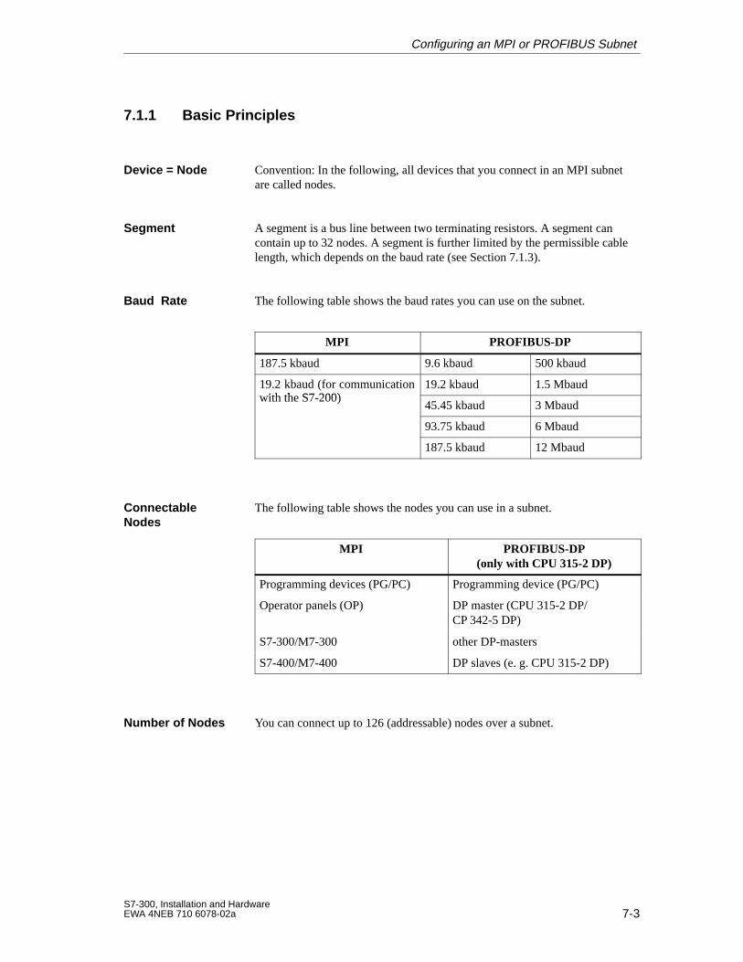
7-3S7-300, Installation and HardwareEWA 4NEB 710 6078-02a
7.1.1 Basic Principles
Convention: In the following, all devices that you connect in an MPI subnetare called nodes.
A segment is a bus line between two terminating resistors. A segment cancontain up to 32 nodes. A segment is further limited by the permissible cablelength, which depends on the baud rate (see Section 7.1.3).
The following table shows the baud rates you can use on the subnet.
MPI PROFIBUS-DP
187.5 kbaud 9.6 kbaud 500 kbaud
19.2 kbaud (for communicationwith the S7 200)
19.2 kbaud 1.5 Mbaud(with the S7-200)
45.45 kbaud 3 Mbaud
93.75 kbaud 6 Mbaud
187.5 kbaud 12 Mbaud
The following table shows the nodes you can use in a subnet.
MPI PROFIBUS-DP(only with CPU 315-2 DP)
Programming devices (PG/PC) Programming device (PG/PC)
Operator panels (OP) DP master (CPU 315-2 DP/CP 342-5 DP)
S7-300/M7-300 other DP-masters
S7-400/M7-400 DP slaves (e. g. CPU 315-2 DP)
You can connect up to 126 (addressable) nodes over a subnet.
Device = Node
Segment
Baud Rate
ConnectableNodes
Number of Nodes
Configuring an MPI or PROFIBUS Subnet
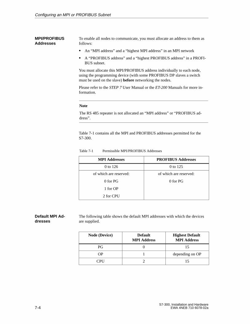
7-4S7-300, Installation and Hardware
EWA 4NEB 710 6078-02a
To enable all nodes to communicate, you must allocate an address to them asfollows:
An “MPI address” and a “highest MPI address” in an MPI network
A “PROFIBUS address” and a “highest PROFIBUS address” in a PROFI-BUS subnet.
You must allocate this MPI/PROFIBUS address individually to each node,using the programming device (with some PROFIBUS DP slaves a switchmust be used on the slave) before networking the nodes.
Please refer to the STEP 7 User Manual or the ET-200 Manuals for more in-formation.
Note
The RS 485 repeater is not allocated an “MPI address” or “PROFIBUS ad-dress”.
Table 7-1 contains all the MPI and PROFIBUS addresses permitted for theS7-300.
Table 7-1 Permissible MPI/PROFIBUS Addresses
MPI Addresses PROFIBUS Addresses
0 to 126 0 to 125
of which are reserved:
0 for PG
1 for OP
2 for CPU
of which are reserved:
0 for PG
The following table shows the default MPI addresses with which the devicesare supplied.
Node (Device) DefaultMPI Addr ess
Highest Default MPI Addr ess
PG 0 15
OP 1 depending on OP
CPU 2 15
MPI/PROFIBUSAddresses
Default MPI Ad-dresses
Configuring an MPI or PROFIBUS Subnet
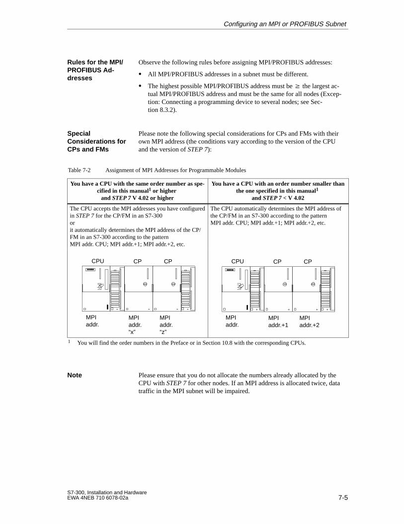
7-5S7-300, Installation and HardwareEWA 4NEB 710 6078-02a
Observe the following rules before assigning MPI/PROFIBUS addresses:
All MPI/PROFIBUS addresses in a subnet must be different.
The highest possible MPI/PROFIBUS address must be the largest ac-tual MPI/PROFIBUS address and must be the same for all nodes (Excep-tion: Connecting a programming device to several nodes; see Sec-tion 8.3.2).
Please note the following special considerations for CPs and FMs with theirown MPI address (the conditions vary according to the version of the CPUand the version of STEP 7):
Table 7-2 Assignment of MPI Addresses for Programmable Modules
You have a CPU with the same order number as spe-cified in this manual1 or higher
and STEP 7 V 4.02 or higher
You have a CPU with an order number smaller thanthe one specified in this manual1
and STEP 7 < V 4.02
The CPU accepts the MPI addresses you have configuredin STEP 7 for the CP/FM in an S7-300orit automatically determines the MPI address of the CP/FM in an S7-300 according to the pattern MPI addr. CPU; MPI addr.+1; MPI addr.+2, etc.
The CPU automatically determines the MPI address ofthe CP/FM in an S7-300 according to the pattern MPI addr. CPU; MPI addr.+1; MPI addr.+2, etc.
MPIaddr.
MPIaddr.“x”
MPIaddr.“z”
CPU CP CP
MPIaddr.
MPIaddr.+1
MPIaddr.+2
CPU CP CP
1 You will find the order numbers in the Preface or in Section 10.8 with the corresponding CPUs.
Please ensure that you do not allocate the numbers already allocated by theCPU with STEP 7 for other nodes. If an MPI address is allocated twice, datatraffic in the MPI subnet will be impaired.
Rules for the MPI/PROFIBUS Ad -dresses
SpecialConsiderations forCPs and FMs
Note
Configuring an MPI or PROFIBUS Subnet
7-6S7-300, Installation and Hardware
EWA 4NEB 710 6078-02a
CPU 315-2 DP: As an alternative to using the MPI interface you can also usethe PROFIBUS-DP interface to program the CPU or execute the PG func-tions “Monitor” and “Modify”. If you are using the CPU 315-2 DP as a DPslave, you must enable these functions when configuring the CPU in STEP7.
Note
The use of Monitor and Modify via the PROFIBUS-DP interface lengthensthe DP cycle.
You must not plug in or remove any modules (SM, FM, CP) of an S7-300configuration while data are being transmitted over the MPI.
!Warning
If you remove or plug in S7-300 modules (SM, FM, CP) during data trans-mission via the MPI, the data might be corrupted by disturbing pulses.
You must not plug in or remove modules (SM, FM, CP) of an S7-300 config-uration during data transmission via the MPI!
Please note the following special characteristics of the MPI subnet:
!Warning
Loss of data packets in the MPI subnet!
Connecting an additionnal CPU to the MPI subnet during running operationcan lead to loss of GD packets and to an increase in cycle time.
Remedy:
1. Disconnect the node to be connected from the supply.
2. Connect the node to the MPI subnet.
3. Switch the node on.
If a short-circuit occurs (between cables A and B) on a bus cable in parame-terized communication between CPUs, you must observe the following CPUbehavior:
After removing the cause of the short-circuit, the
GD packet which was due to be sent immediately before the short-circuitoccurred will be sent first.
PG Functions viathe PROFIBUS-DPInterface
Plugging in andRemoving Mod -ules in the MPISubnet
Data Packets in theMPI Subnet
Communicationbetween CPUs
Configuring an MPI or PROFIBUS Subnet
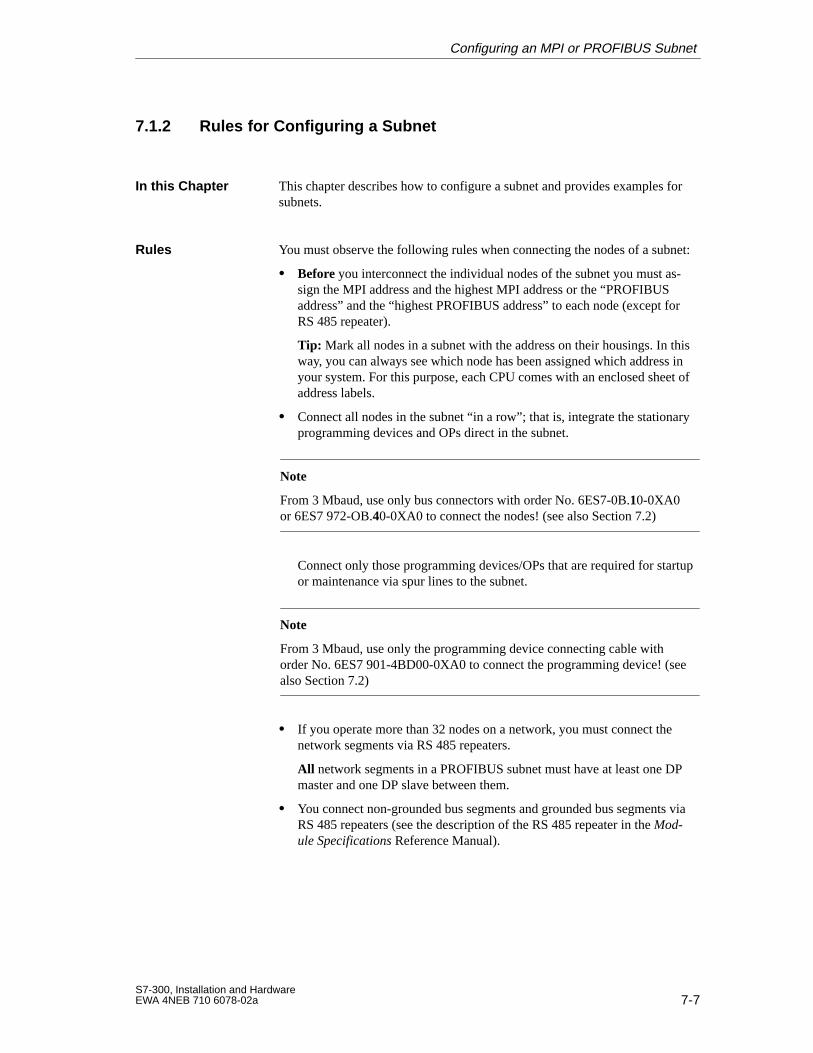
7-7S7-300, Installation and HardwareEWA 4NEB 710 6078-02a
7.1.2 Rules for Configuring a Subnet
This chapter describes how to configure a subnet and provides examples forsubnets.
You must observe the following rules when connecting the nodes of a subnet:
Before you interconnect the individual nodes of the subnet you must as-sign the MPI address and the highest MPI address or the “PROFIBUSaddress” and the “highest PROFIBUS address” to each node (except forRS 485 repeater).
Tip: Mark all nodes in a subnet with the address on their housings. In thisway, you can always see which node has been assigned which address inyour system. For this purpose, each CPU comes with an enclosed sheet ofaddress labels.
Connect all nodes in the subnet “in a row”; that is, integrate the stationaryprogramming devices and OPs direct in the subnet.
Note
From 3 Mbaud, use only bus connectors with order No. 6ES7-0B.10-0XA0or 6ES7 972-OB.40-0XA0 to connect the nodes! (see also Section 7.2)
Connect only those programming devices/OPs that are required for startupor maintenance via spur lines to the subnet.
Note
From 3 Mbaud, use only the programming device connecting cable with order No. 6ES7 901-4BD00-0XA0 to connect the programming device! (seealso Section 7.2)
If you operate more than 32 nodes on a network, you must connect thenetwork segments via RS 485 repeaters.
All network segments in a PROFIBUS subnet must have at least one DPmaster and one DP slave between them.
You connect non-grounded bus segments and grounded bus segments viaRS 485 repeaters (see the description of the RS 485 repeater in the Mod-ule Specifications Reference Manual).
In this Chapter
Rules
Configuring an MPI or PROFIBUS Subnet
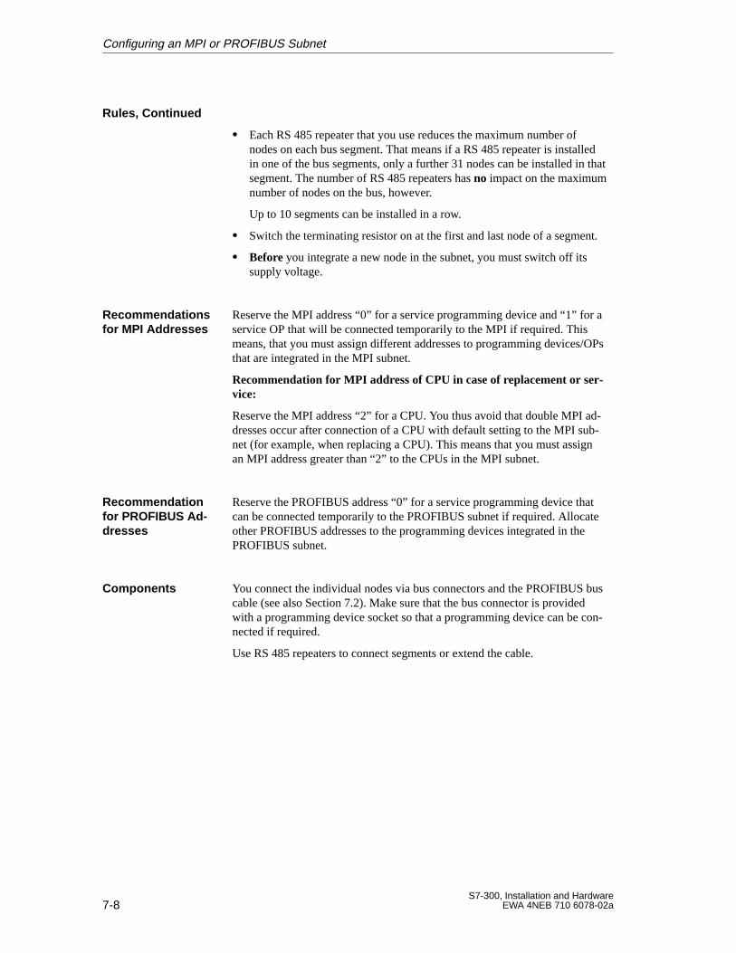
7-8S7-300, Installation and Hardware
EWA 4NEB 710 6078-02a
Each RS 485 repeater that you use reduces the maximum number ofnodes on each bus segment. That means if a RS 485 repeater is installedin one of the bus segments, only a further 31 nodes can be installed in thatsegment. The number of RS 485 repeaters has no impact on the maximumnumber of nodes on the bus, however.
Up to 10 segments can be installed in a row.
Switch the terminating resistor on at the first and last node of a segment.
Before you integrate a new node in the subnet, you must switch off itssupply voltage.
Reserve the MPI address “0” for a service programming device and “1” for aservice OP that will be connected temporarily to the MPI if required. Thismeans, that you must assign different addresses to programming devices/OPsthat are integrated in the MPI subnet.
Recommendation for MPI address of CPU in case of replacement or ser-vice:
Reserve the MPI address “2” for a CPU. You thus avoid that double MPI ad-dresses occur after connection of a CPU with default setting to the MPI sub-net (for example, when replacing a CPU). This means that you must assignan MPI address greater than “2” to the CPUs in the MPI subnet.
Reserve the PROFIBUS address “0” for a service programming device thatcan be connected temporarily to the PROFIBUS subnet if required. Allocateother PROFIBUS addresses to the programming devices integrated in thePROFIBUS subnet.
You connect the individual nodes via bus connectors and the PROFIBUS buscable (see also Section 7.2). Make sure that the bus connector is providedwith a programming device socket so that a programming device can be con-nected if required.
Use RS 485 repeaters to connect segments or extend the cable.
Rules, Continued
Recommendationsfor MPI Addresses
Recommendationfor PROFIBUS Ad -dresses
Components
Configuring an MPI or PROFIBUS Subnet
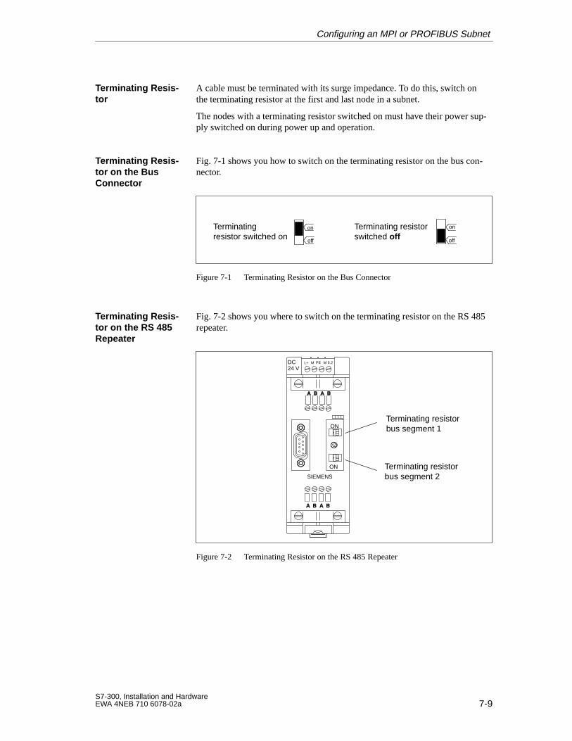
7-9S7-300, Installation and HardwareEWA 4NEB 710 6078-02a
A cable must be terminated with its surge impedance. To do this, switch onthe terminating resistor at the first and last node in a subnet.
The nodes with a terminating resistor switched on must have their power sup-ply switched on during power up and operation.
Fig. 7-1 shows you how to switch on the terminating resistor on the bus con-nector.
Terminating resistor switched on
Terminating resistorswitched off
on
off
on
off
Figure 7-1 Terminating Resistor on the Bus Connector
Fig. 7-2 shows you where to switch on the terminating resistor on the RS 485repeater.
Terminating resistorbus segment 1
Terminating resistorbus segment 2
DC24 V
L+ M PE M 5.2
SIEMENS
ON
ON
Figure 7-2 Terminating Resistor on the RS 485 Repeater
Terminating Resis -tor
Terminating Resis -tor on the BusConnector
Terminating Resis -tor on the RS 485Repeater
Configuring an MPI or PROFIBUS Subnet
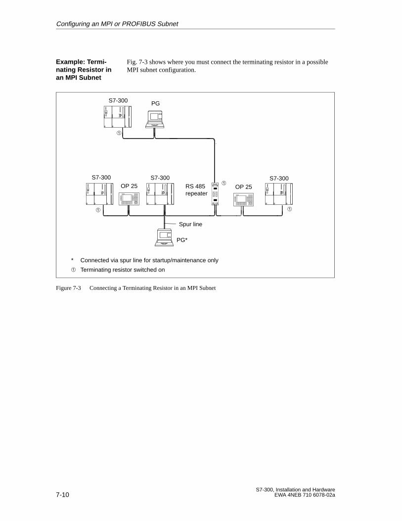
7-10S7-300, Installation and Hardware
EWA 4NEB 710 6078-02a
Fig. 7-3 shows where you must connect the terminating resistor in a possibleMPI subnet configuration.
RS 485repeater
Terminating resistor switched on
S7-300 S7-300
S7-300
Spur line
S7-300
OP 25 OP 25
PG
PG*
* Connected via spur line for startup/maintenance only
Figure 7-3 Connecting a Terminating Resistor in an MPI Subnet
Example: Termi-nating Resistor inan MPI Subnet
Configuring an MPI or PROFIBUS Subnet
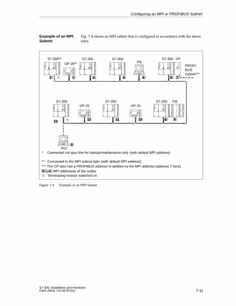
7-11S7-300, Installation and HardwareEWA 4NEB 710 6078-02a
Fig. 7-4 shows an MPI subnet that is configured in accordance with the aboverules.
S7-300** S7-300 S7-300 S7-300
S7-300S7-300
* Connected via spur line for startup/maintenance only (with default MPI address)
S7-300
** Connected to the MPI subnet later (with default MPI address)
0
13
0 ... x MPI addresses of the nodes
9101112
12 3 4 5 6
PG*
OP 25 OP 25
PGOP 25**
Terminating resistor switched on
*** The CP also has a PROFIBUS address in addition to the MPI address (address 7 here)
FM
8
CP
7
PROFI-BUSsubnet***
Figure 7-4 Example of an MPI Subnet
Example of an MPISubnet
Configuring an MPI or PROFIBUS Subnet
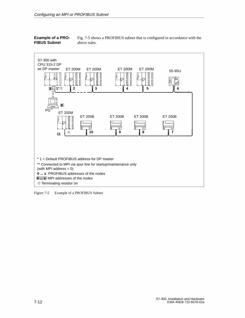
7-12S7-300, Installation and Hardware
EWA 4NEB 710 6078-02a
Fig. 7-5 shows a PROFIBUS subnet that is configured in accordance with theabove rules.
** Connected to MPI via spur line for startup/maintenance only (with MPI address = 0)0 ... x PROFIBUS addresses of the nodes
S7-300 withCPU 315-2 DPas DP master ET 200M
0
11 78910
2 3 4 5 6
ET 200M S5-95U
ET 200BET 200B
Terminating resistor on
ET 200MET 200M
ET 200MET 200B ET 200B
PG**
* 1 = Default PROFIBUS address for DP master
1*3
0 ... x MPI addresses of the nodes
Figure 7-5 Example of a PROFIBUS Subnet
Example of a PRO-FIBUS Subnet
Configuring an MPI or PROFIBUS Subnet
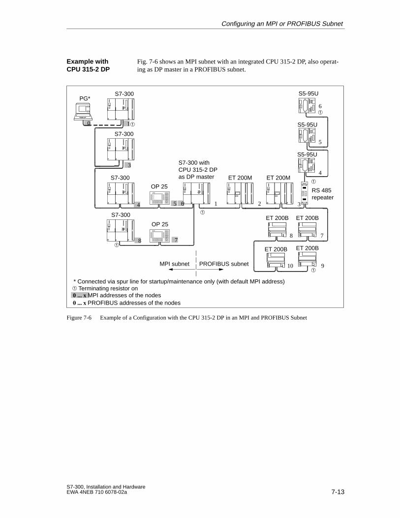
7-13S7-300, Installation and HardwareEWA 4NEB 710 6078-02a
Fig. 7-6 shows an MPI subnet with an integrated CPU 315-2 DP, also operat-ing as DP master in a PROFIBUS subnet.
OP 25
S7-300
S7-300 withCPU 315-2 DPas DP master ET 200M
S5-95U
ET 200B
RS 485repeater
PG*
S7-300
S7-300
S7-300
OP 25
ET 200M
S5-95U
ET 200B
Terminating resistor on* Connected via spur line for startup/maintenance only (with default MPI address)
S5-95U
ET 200B
ET 200B
1
3
4 5 6
8 7
1 2 3
4
5
6
8 7
10 9
0 ... x MPI addresses of the nodes PROFIBUS addresses of the nodes
0
PROFIBUS subnet
MPI subnet
Figure 7-6 Example of a Configuration with the CPU 315-2 DP in an MPI and PROFIBUS Subnet
Example withCPU 315-2 DP
Configuring an MPI or PROFIBUS Subnet
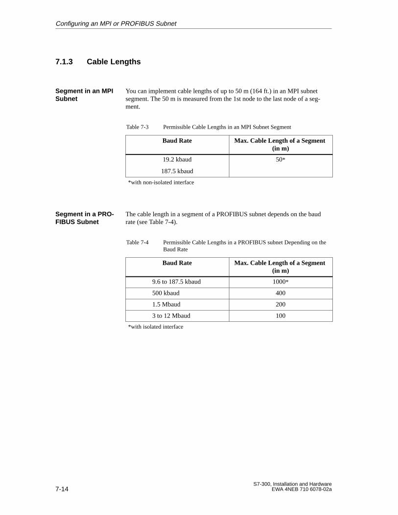
7-14S7-300, Installation and Hardware
EWA 4NEB 710 6078-02a
7.1.3 Cable Lengths
You can implement cable lengths of up to 50 m (164 ft.) in an MPI subnetsegment. The 50 m is measured from the 1st node to the last node of a seg-ment.
Table 7-3 Permissible Cable Lengths in an MPI Subnet Segment
Baud Rate Max. Cable Length of a Segment (in m)
19.2 kbaud
187.5 kbaud
50*
*with non-isolated interface
The cable length in a segment of a PROFIBUS subnet depends on the baudrate (see Table 7-4).
Table 7-4 Permissible Cable Lengths in a PROFIBUS subnet Depending on theBaud Rate
Baud Rate Max. Cable Length of a Segment (in m)
9.6 to 187.5 kbaud 1000*
500 kbaud 400
1.5 Mbaud 200
3 to 12 Mbaud 100
*with isolated interface
Segment in an MPISubnet
Segment in a PRO -FIBUS Subnet
Configuring an MPI or PROFIBUS Subnet
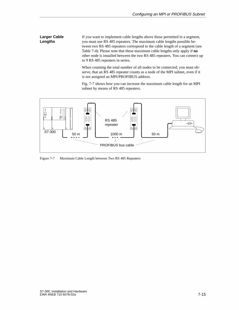
7-15S7-300, Installation and HardwareEWA 4NEB 710 6078-02a
If you want to implement cable lengths above those permitted in a segment,you must use RS 485 repeaters. The maximum cable lengths possible be-tween two RS 485 repeaters correspond to the cable length of a segment (seeTable 7-4). Please note that these maximum cable lengths only apply if noother node is installed between the two RS 485 repeaters. You can connect upto 9 RS 485 repeaters in series.
When counting the total number of all nodes to be connected, you must ob-serve, that an RS 485 repeater counts as a node of the MPI subnet, even if itis not assigned an MPI/PROFIBUS address.
Fig. 7-7 shows how you can increase the maximum cable length for an MPIsubnet by means of RS 485 repeaters.
S7-30050 m 1000 m 50 m
RS 485repeater
PROFIBUS bus cable
Figure 7-7 Maximum Cable Length between Two RS 485 Repeaters
Larger CableLengths
Configuring an MPI or PROFIBUS Subnet
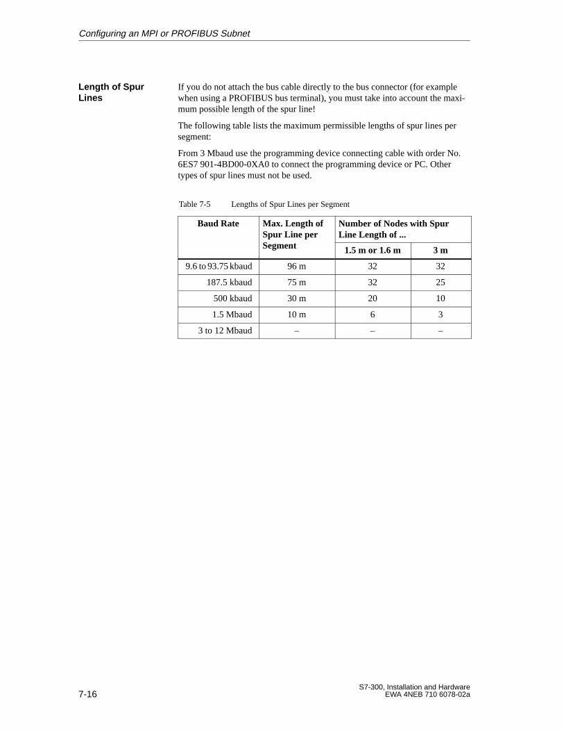
7-16S7-300, Installation and Hardware
EWA 4NEB 710 6078-02a
If you do not attach the bus cable directly to the bus connector (for examplewhen using a PROFIBUS bus terminal), you must take into account the maxi-mum possible length of the spur line!
The following table lists the maximum permissible lengths of spur lines persegment:
From 3 Mbaud use the programming device connecting cable with order No.6ES7 901-4BD00-0XA0 to connect the programming device or PC. Othertypes of spur lines must not be used.
Table 7-5 Lengths of Spur Lines per Segment
Baud Rate Max. Length ofSpur Line perS t
Number of Nodes with SpurLine Length of ...p p
Segment 1.5 m or 1.6 m 3 m
9.6 to 93.75 kbaud 96 m 32 32
187.5 kbaud 75 m 32 25
500 kbaud 30 m 20 10
1.5 Mbaud 10 m 6 3
3 to 12 Mbaud – – –
Length of SpurLines
Configuring an MPI or PROFIBUS Subnet
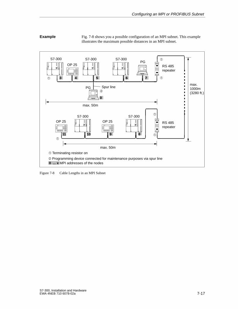
7-17S7-300, Installation and HardwareEWA 4NEB 710 6078-02a
Fig. 7-8 shows you a possible configuration of an MPI subnet. This exampleillustrates the maximum possible distances in an MPI subnet.
RS 485repeater
RS 485repeater
max. 50m
max. 50m
max.1000m(3280 ft.)
Terminating resistor on
S7-300 S7-300 S7-300
S7-300 S7-300
Spur line
Programming device connected for maintenance purposes via spur line
0
11
0 ... x MPI addresses of the nodes
7
8910
3 4 5 6
OP 25
PG
PG
OP 25
OP 25
Figure 7-8 Cable Lengths in an MPI Subnet
Example
Configuring an MPI or PROFIBUS Subnet
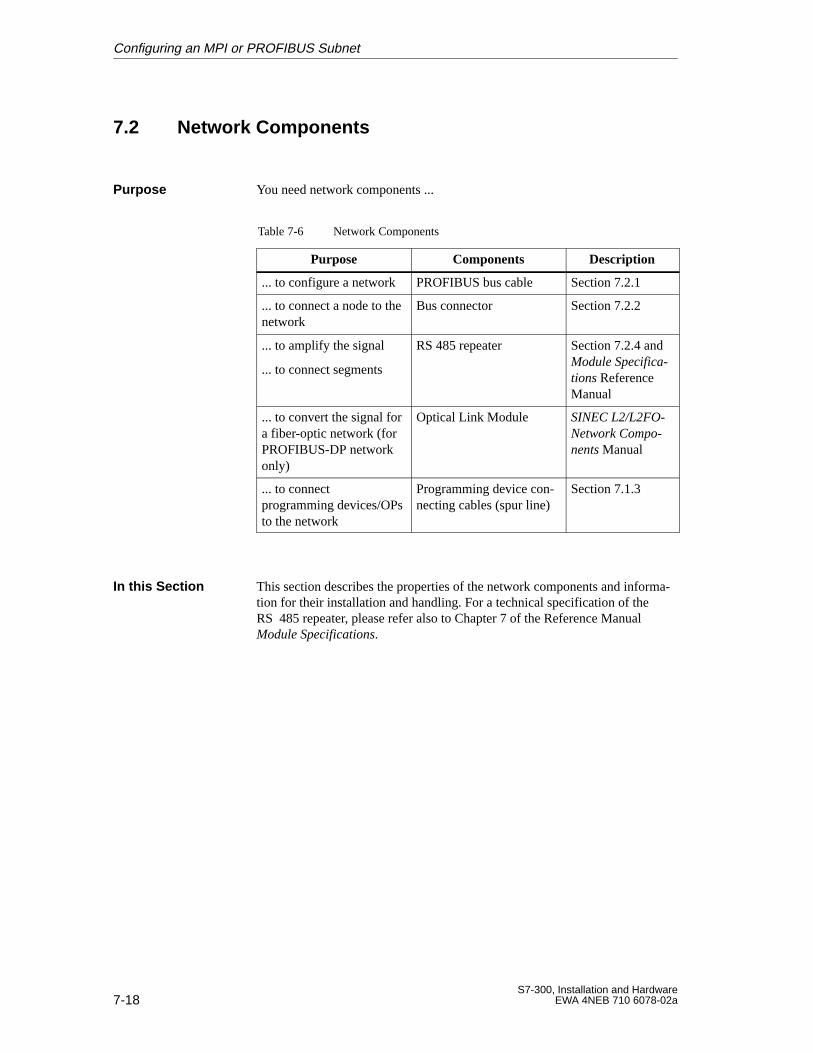
7-18S7-300, Installation and Hardware
EWA 4NEB 710 6078-02a
7.2 Network Components
You need network components ...
Table 7-6 Network Components
Purpose Components Description
... to configure a network PROFIBUS bus cable Section 7.2.1
... to connect a node to thenetwork
Bus connector Section 7.2.2
... to amplify the signal
... to connect segments
RS 485 repeater Section 7.2.4 andModule Specifica-tions ReferenceManual
... to convert the signal fora fiber-optic network (forPROFIBUS-DP networkonly)
Optical Link Module SINEC L2/L2FO-Network Compo-nents Manual
... to connectprogramming devices/OPsto the network
Programming device con-necting cables (spur line)
Section 7.1.3
This section describes the properties of the network components and informa-tion for their installation and handling. For a technical specification of theRS 485 repeater, please refer also to Chapter 7 of the Reference ManualModule Specifications.
Purpose
In this Section
Configuring an MPI or PROFIBUS Subnet
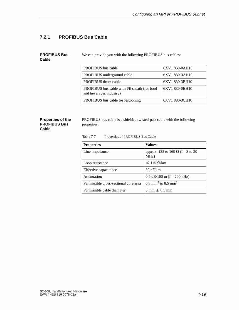
7-19S7-300, Installation and HardwareEWA 4NEB 710 6078-02a
7.2.1 PROFIBUS Bus Cable
We can provide you with the following PROFIBUS bus cables:
PROFIBUS bus cable 6XV1 830-0AH10
PROFIBUS underground cable 6XV1 830-3AH10
PROFIBUS drum cable 6XV1 830-3BH10
PROFIBUS bus cable with PE sheath (for foodand beverages industry)
6XV1 830-0BH10
PROFIBUS bus cable for festooning 6XV1 830-3CH10
PROFIBUS bus cable is a shielded twisted-pair cable with the followingproperties:
Table 7-7 Properties of PROFIBUS Bus Cable
Properties Values
Line impedance approx. 135 to 160 Ω (f = 3 to 20MHz)
Loop resistance 115 Ω/km
Effective capacitance 30 nF/km
Attenuation 0.9 dB/100 m (f = 200 kHz)
Permissible cross-sectional core area0.3 mm2 to 0.5 mm2
Permissible cable diameter 8 mm 0.5 mm
PROFIBUS BusCable
Properties of thePROFIBUS BusCable
Configuring an MPI or PROFIBUS Subnet
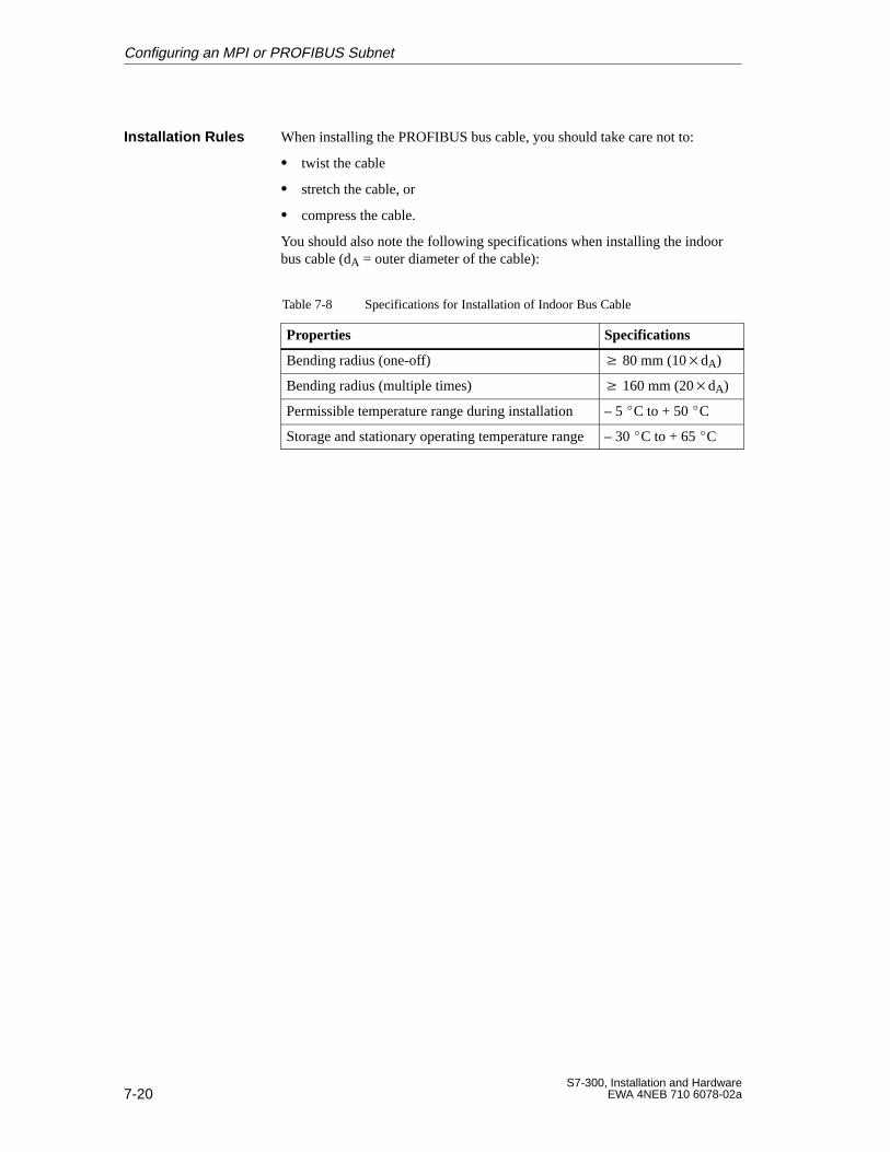
7-20S7-300, Installation and Hardware
EWA 4NEB 710 6078-02a
When installing the PROFIBUS bus cable, you should take care not to:
twist the cable
stretch the cable, or
compress the cable.
You should also note the following specifications when installing the indoorbus cable (dA = outer diameter of the cable):
Table 7-8 Specifications for Installation of Indoor Bus Cable
Properties Specifications
Bending radius (one-off) 80 mm (10dA)
Bending radius (multiple times) 160 mm (20dA)
Permissible temperature range during installation – 5 C to + 50 C
Storage and stationary operating temperature range– 30 C to + 65 C
Installation Rules
Configuring an MPI or PROFIBUS Subnet
7-21S7-300, Installation and HardwareEWA 4NEB 710 6078-02a
7.2.2 Bus Connectors
The bus connector is used to connect the PROFIBUS cable to the MPI orPROFIBUS-DP interface. You thus make the connections to further nodes.
The following bus connectors are available:
Up to 12 Mbaud
– without programming device socket(6ES7 972-0BA10-0XA0)
– with programming device socket (6ES7 972-0BB10-0XA0)
up to 12 Mbaud, angular outgoing cable
– without programming device socket(6ES7 972-0BA40-0XA0)
– with programming device socket (6ES7 972-0BB40-0XA0)
You do not require the bus connector for:
DP slaves in degree of protection IP 65 (e.g. ET 200C)
RS 485 repeaters
Purpose of theBus Connector
No ApplicationArea
Configuring an MPI or PROFIBUS Subnet
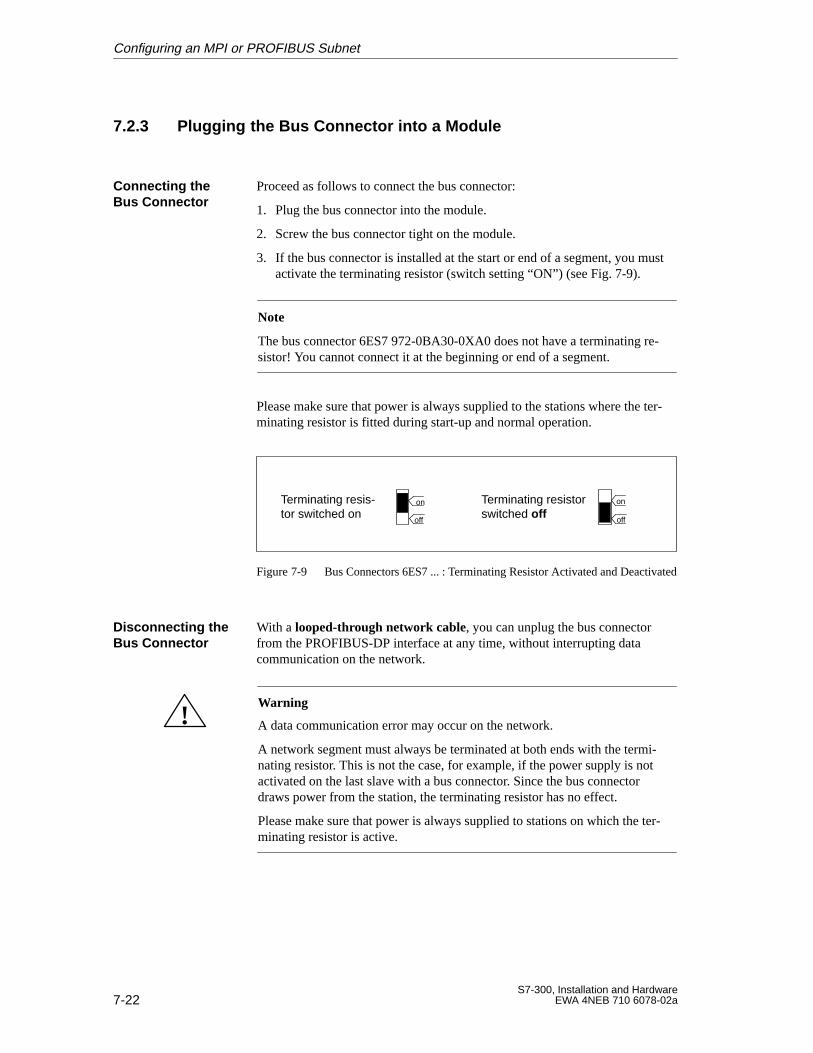
7-22S7-300, Installation and Hardware
EWA 4NEB 710 6078-02a
7.2.3 Plugging the Bus Connector into a Module
Proceed as follows to connect the bus connector:
1. Plug the bus connector into the module.
2. Screw the bus connector tight on the module.
3. If the bus connector is installed at the start or end of a segment, you mustactivate the terminating resistor (switch setting “ON”) (see Fig. 7-9).
Note
The bus connector 6ES7 972-0BA30-0XA0 does not have a terminating re-sistor! You cannot connect it at the beginning or end of a segment.
Please make sure that power is always supplied to the stations where the ter-minating resistor is fitted during start-up and normal operation.
Terminating resis-tor switched on
Terminating resistorswitched off
on
off
on
off
Figure 7-9 Bus Connectors 6ES7 ... : Terminating Resistor Activated and Deactivated
With a looped-through network cable, you can unplug the bus connectorfrom the PROFIBUS-DP interface at any time, without interrupting datacommunication on the network.
!Warning
A data communication error may occur on the network.
A network segment must always be terminated at both ends with the termi-nating resistor. This is not the case, for example, if the power supply is notactivated on the last slave with a bus connector. Since the bus connectordraws power from the station, the terminating resistor has no effect.
Please make sure that power is always supplied to stations on which the ter-minating resistor is active.
Connecting theBus Connector
Disconnecting theBus Connector
Configuring an MPI or PROFIBUS Subnet
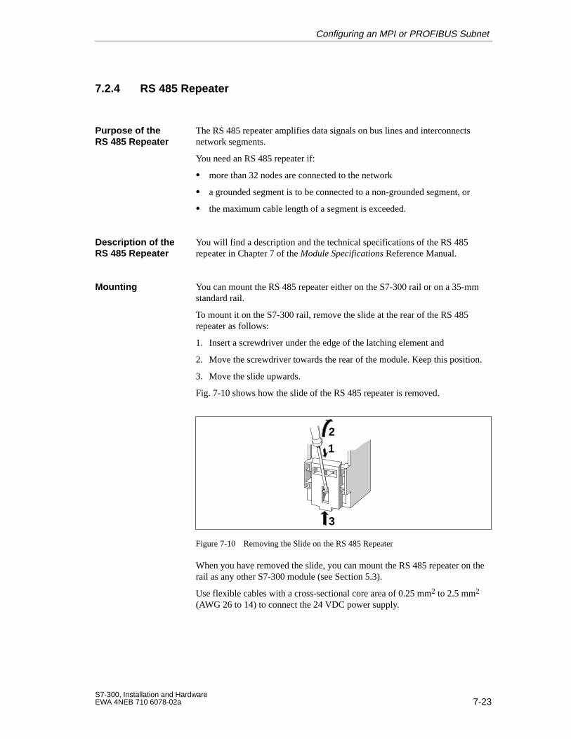
7-23S7-300, Installation and HardwareEWA 4NEB 710 6078-02a
7.2.4 RS 485 Repeater
The RS 485 repeater amplifies data signals on bus lines and interconnectsnetwork segments.
You need an RS 485 repeater if:
more than 32 nodes are connected to the network
a grounded segment is to be connected to a non-grounded segment, or
the maximum cable length of a segment is exceeded.
You will find a description and the technical specifications of the RS 485repeater in Chapter 7 of the Module Specifications Reference Manual.
You can mount the RS 485 repeater either on the S7-300 rail or on a 35-mmstandard rail.
To mount it on the S7-300 rail, remove the slide at the rear of the RS 485repeater as follows:
1. Insert a screwdriver under the edge of the latching element and
2. Move the screwdriver towards the rear of the module. Keep this position.
3. Move the slide upwards.
Fig. 7-10 shows how the slide of the RS 485 repeater is removed.
3
1
2
Figure 7-10 Removing the Slide on the RS 485 Repeater
When you have removed the slide, you can mount the RS 485 repeater on therail as any other S7-300 module (see Section 5.3).
Use flexible cables with a cross-sectional core area of 0.25 mm2 to 2.5 mm2
(AWG 26 to 14) to connect the 24 VDC power supply.
Purpose of theRS 485 Repeater
Description of theRS 485 Repeater
Mounting
Configuring an MPI or PROFIBUS Subnet
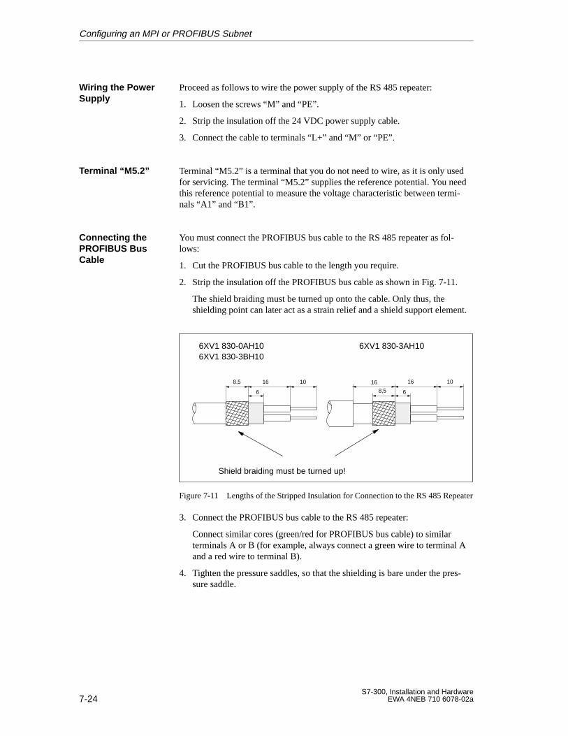
7-24S7-300, Installation and Hardware
EWA 4NEB 710 6078-02a
Proceed as follows to wire the power supply of the RS 485 repeater:
1. Loosen the screws “M” and “PE”.
2. Strip the insulation off the 24 VDC power supply cable.
3. Connect the cable to terminals “L+” and “M” or “PE”.
Terminal “M5.2” is a terminal that you do not need to wire, as it is only usedfor servicing. The terminal “M5.2” supplies the reference potential. You needthis reference potential to measure the voltage characteristic between termi-nals “A1” and “B1”.
You must connect the PROFIBUS bus cable to the RS 485 repeater as fol-lows:
1. Cut the PROFIBUS bus cable to the length you require.
2. Strip the insulation off the PROFIBUS bus cable as shown in Fig. 7-11.
The shield braiding must be turned up onto the cable. Only thus, theshielding point can later act as a strain relief and a shield support element.
6XV1 830-0AH106XV1 830-3BH10
6XV1 830-3AH10
Shield braiding must be turned up!
8,5 16 10
6 8,5
16 10
6
16
Figure 7-11 Lengths of the Stripped Insulation for Connection to the RS 485 Repeater
3. Connect the PROFIBUS bus cable to the RS 485 repeater:
Connect similar cores (green/red for PROFIBUS bus cable) to similarterminals A or B (for example, always connect a green wire to terminal Aand a red wire to terminal B).
4. Tighten the pressure saddles, so that the shielding is bare under the pres-sure saddle.
Wiring the PowerSupply
Terminal “M5.2”
Connecting thePROFIBUS BusCable
Configuring an MPI or PROFIBUS Subnet
8-1S7-300, Installation and HardwareEWA 4NEB 710 6078-02a
Preparing an S7-300 for Operation andStart-up of PROFIBUS-DP
This chapter tells you what you must do before taking the S7-300 into service
Plug in the memory card (not CPU 312 IFM/314 IFM)
You require the memory card only if you want to expand the loadmemory of your CPU or to store the user program so that it is protectedagainst power failure.
Insert the backup battery (only when CPU in POWER UP) or recharge-able battery.
You require the backup battery (notCPU 312 IFM) ...
You require the backup battery (not CPU 312 IFM/313) ...
to retain an amount of data greaterth th t ibl ith t
if backup is required for the real-timel k l
gthan the amount possible without backup battery
p qclock only.
backup battery
for backup of the real-time clock for backup of the real-time clock
if the user program is not stored on a if the user program is not stored on amemory card
Connect the programming device
Reset the CPU memory
If you use the CPU 315-2 DP as DP master or DP slave, you should refer toSection 8.5 “PROFIBUS-DP Startup”. This chapter provides you with rulesand tips for the hardware startup of PROFIBUS-DP.
The sections in this chapter describe the following:
Section Contents Page
8.1 Plug in the memory card (Not CPU 312 IFM/314 IFM) 8-2
8.2 Inserting the Backup Battery or Rechargeable Battery (NotCPU 312 IFM)
8-4
8.3 Connect the Programming Device 8-6
8.4 Reset the CPU Memory 8-11
8.5 PROFIBUS-DP Startup 8-14
What‘s Involved inPreparation
PROFIBUS-DP
In this Chapter
8
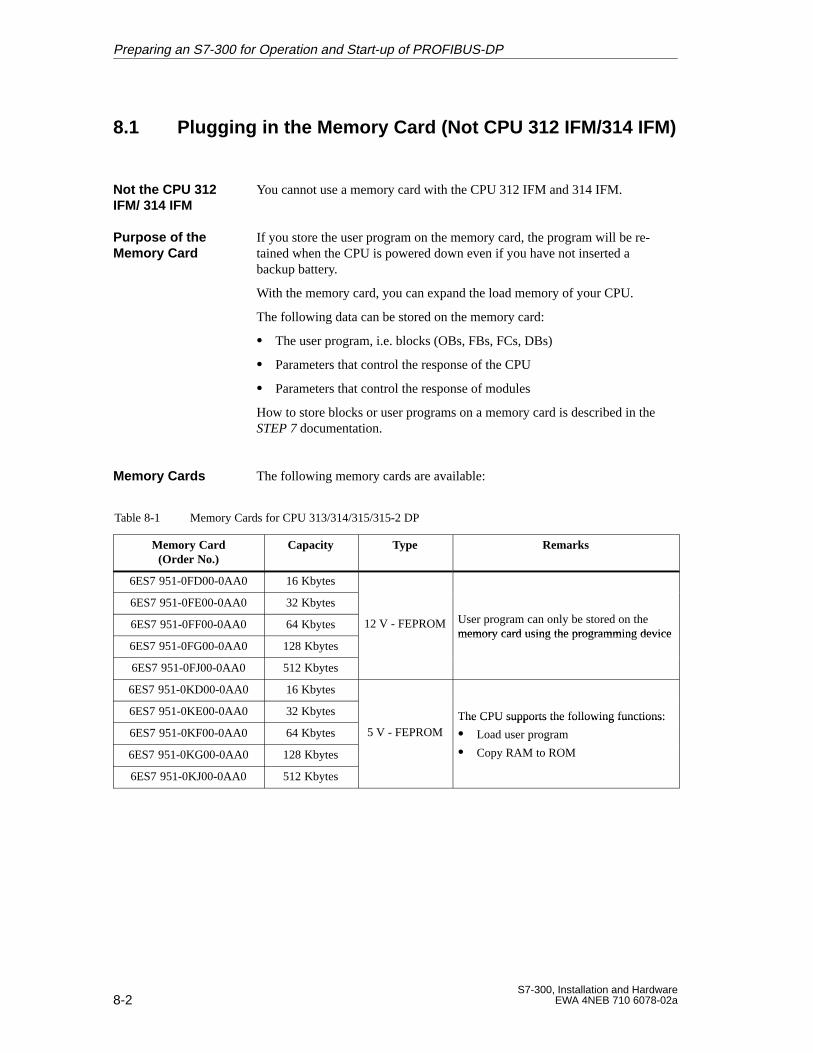
8-2S7-300, Installation and Hardware
EWA 4NEB 710 6078-02a
8.1 Plugging in the Memory Card (Not CPU 312 IFM/314 IFM)
You cannot use a memory card with the CPU 312 IFM and 314 IFM.
If you store the user program on the memory card, the program will be re-tained when the CPU is powered down even if you have not inserted abackup battery.
With the memory card, you can expand the load memory of your CPU.
The following data can be stored on the memory card:
The user program, i.e. blocks (OBs, FBs, FCs, DBs)
Parameters that control the response of the CPU
Parameters that control the response of modules
How to store blocks or user programs on a memory card is described in theSTEP 7 documentation.
The following memory cards are available:
Table 8-1 Memory Cards for CPU 313/314/315/315-2 DP
Memory Card(Order No.)
Capacity Type Remarks
6ES7 951-0FD00-0AA0 16 Kbytes
6ES7 951-0FE00-0AA0 32 KbytesU l b d h6ES7 951-0FF00-0AA0 64 Kbytes 12 V - FEPROM User program can only be stored on thememory card using the programming device
6ES7 951-0FG00-0AA0 128 Kbytesmemory card using the programming device
6ES7 951-0FJ00-0AA0 512 Kbytes
6ES7 951-0KD00-0AA0 16 Kbytes
6ES7 951-0KE00-0AA0 32 Kbytes The CPU supports the following functions:
6ES7 951-0KF00-0AA0 64 Kbytes 5 V - FEPROMThe CPU supports the following functions:
Load user program
6ES7 951-0KG00-0AA0 128 Kbytes
p g
Copy RAM to ROM
6ES7 951-0KJ00-0AA0 512 Kbytes
Not the CPU 312IFM/ 314 IFM
Purpose of theMemory Card
Memory Cards
Preparing an S7-300 for Operation and Start-up of PROFIBUS-DP
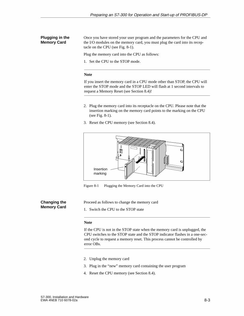
8-3S7-300, Installation and HardwareEWA 4NEB 710 6078-02a
Once you have stored your user program and the parameters for the CPU andthe I/O modules on the memory card, you must plug the card into its recep-tacle on the CPU (see Fig.8-1).
Plug the memory card into the CPU as follows:
1. Set the CPU to the STOP mode.
Note
If you insert the memory card in a CPU mode other than STOP, the CPU willenter the STOP mode and the STOP LED will flash at 1 second intervals torequest a Memory Reset (see Section 8.4)!
2. Plug the memory card into its receptacle on the CPU. Please note that theinsertion marking on the memory card points to the marking on the CPU(see Fig. 8-1).
3. Reset the CPU memory (see Section 8.4).
Insertionmarking
Figure 8-1 Plugging the Memory Card into the CPU
Proceed as follows to change the memory card
1. Switch the CPU to the STOP state
Note
If the CPU is not in the STOP state when the memory card is unplugged, theCPU switches to the STOP state and the STOP indicator flashes in a one-sec-ond cycle to request a memory reset. This process cannot be controlled byerror OBs.
2. Unplug the memory card
3. Plug in the “new” memory card containing the user program
4. Reset the CPU memory (see Section 8.4).
Plugging in theMemory Card
Changing theMemory Card
Preparing an S7-300 for Operation and Start-up of PROFIBUS-DP
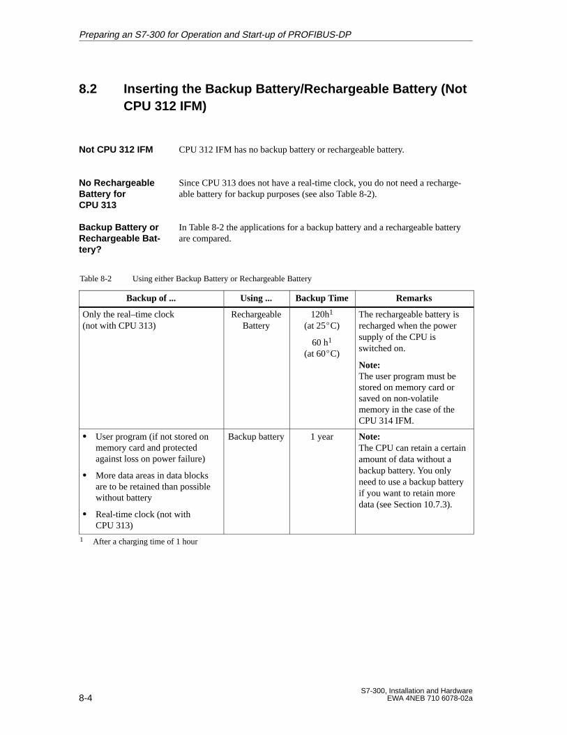
8-4S7-300, Installation and Hardware
EWA 4NEB 710 6078-02a
8.2 Inserting the Backup Battery/Rechargeable Battery (Not CPU 312 IFM)
CPU 312 IFM has no backup battery or rechargeable battery.
Since CPU 313 does not have a real-time clock, you do not need a recharge-able battery for backup purposes (see also Table 8-2).
In Table 8-2 the applications for a backup battery and a rechargeable batteryare compared.
Table 8-2 Using either Backup Battery or Rechargeable Battery
Backup of ... Using ... Backup Time Remarks
Only the real–time clock (not with CPU 313)
RechargeableBattery
120h1
(at 25C)
60 h1
(at 60C)
The rechargeable battery isrecharged when the powersupply of the CPU isswitched on.
Note:The user program must bestored on memory card orsaved on non-volatilememory in the case of theCPU 314 IFM.
User program (if not stored onmemory card and protectedagainst loss on power failure)
More data areas in data blocksare to be retained than possiblewithout battery
Real-time clock (not withCPU 313)
Backup battery 1 year Note:The CPU can retain a certainamount of data without abackup battery. You onlyneed to use a backup batteryif you want to retain moredata (see Section 10.7.3).
1 After a charging time of 1 hour
Not CPU 312 IFM
No RechargeableBattery forCPU 313
Backup Battery orRechargeable Bat -tery?
Preparing an S7-300 for Operation and Start-up of PROFIBUS-DP
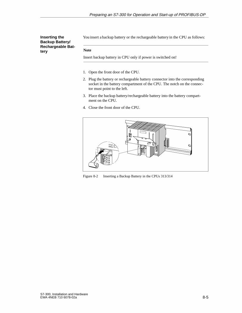
8-5S7-300, Installation and HardwareEWA 4NEB 710 6078-02a
You insert a backup battery or the rechargeable battery in the CPU as follows:
Note
Insert backup battery in CPU only if power is switched on!
1. Open the front door of the CPU.
2. Plug the battery or rechargeable battery connector into the correspondingsocket in the battery compartment of the CPU. The notch on the connec-tor must point to the left.
3. Place the backup battery/rechargeable battery into the battery compart-ment on the CPU.
4. Close the front door of the CPU.
Figure 8-2 Inserting a Backup Battery in the CPUs 313/314
Inserting theBackup Battery/Rechargeable Bat -tery
Preparing an S7-300 for Operation and Start-up of PROFIBUS-DP

8-6S7-300, Installation and Hardware
EWA 4NEB 710 6078-02a
8.3 Connecting a Programming Device
The programming device must be equipped with an integrated MPI interfaceor an MPI card, in order to connect it to an MPI.
This section describes how to connect the programming device
to the MPI of an S7-300
to several networked nodes of a subnet
to ungrounded nodes in a subnet.
Refer to Section 7.1.3 for information on possible cable lenghts.
Requirements
In this Section
Cable Lengths
Preparing an S7-300 for Operation and Start-up of PROFIBUS-DP
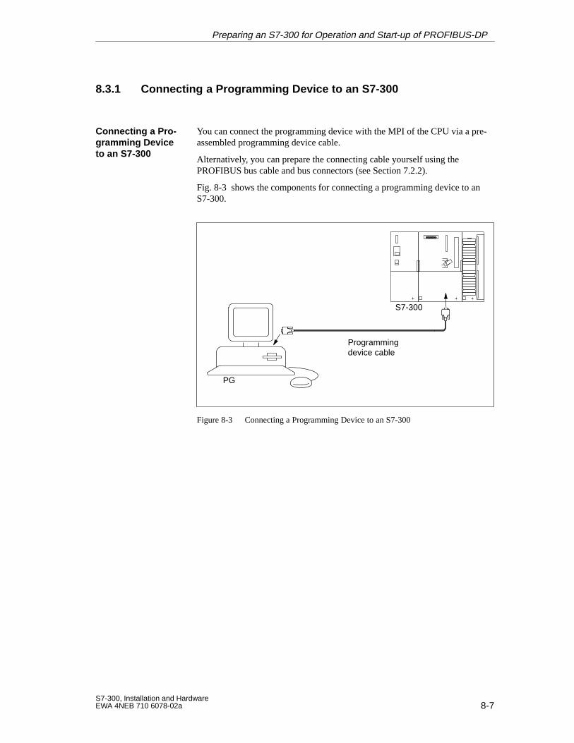
8-7S7-300, Installation and HardwareEWA 4NEB 710 6078-02a
8.3.1 Connecting a Programming Device to an S7-300
You can connect the programming device with the MPI of the CPU via a pre-assembled programming device cable.
Alternatively, you can prepare the connecting cable yourself using the PROFIBUS bus cable and bus connectors (see Section 7.2.2).
Fig. 8-3 shows the components for connecting a programming device to anS7-300.
Programmingdevice cable
S7-300
PG
Figure 8-3 Connecting a Programming Device to an S7-300
Connecting a Pro-gramming Deviceto an S7-300
Preparing an S7-300 for Operation and Start-up of PROFIBUS-DP
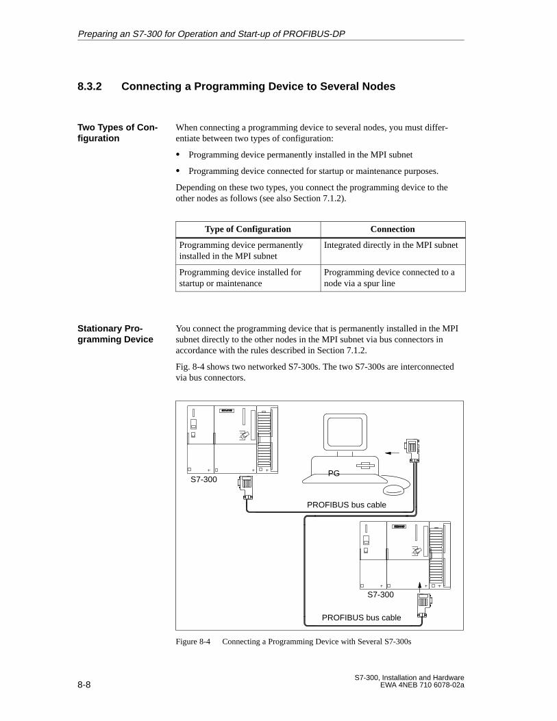
8-8S7-300, Installation and Hardware
EWA 4NEB 710 6078-02a
8.3.2 Connecting a Programming Device to Several Nodes
When connecting a programming device to several nodes, you must differ-entiate between two types of configuration:
Programming device permanently installed in the MPI subnet
Programming device connected for startup or maintenance purposes.
Depending on these two types, you connect the programming device to theother nodes as follows (see also Section 7.1.2).
Type of Configuration Connection
Programming device permanentlyinstalled in the MPI subnet
Integrated directly in the MPI subnet
Programming device installed forstartup or maintenance
Programming device connected to anode via a spur line
You connect the programming device that is permanently installed in the MPIsubnet directly to the other nodes in the MPI subnet via bus connectors inaccordance with the rules described in Section 7.1.2.
Fig. 8-4 shows two networked S7-300s. The two S7-300s are interconnectedvia bus connectors.
PROFIBUS bus cable
S7-300
S7-300
PG
PROFIBUS bus cable
Figure 8-4 Connecting a Programming Device with Several S7-300s
Two Types of Con-figuration
Stationary Pro -gramming Device
Preparing an S7-300 for Operation and Start-up of PROFIBUS-DP
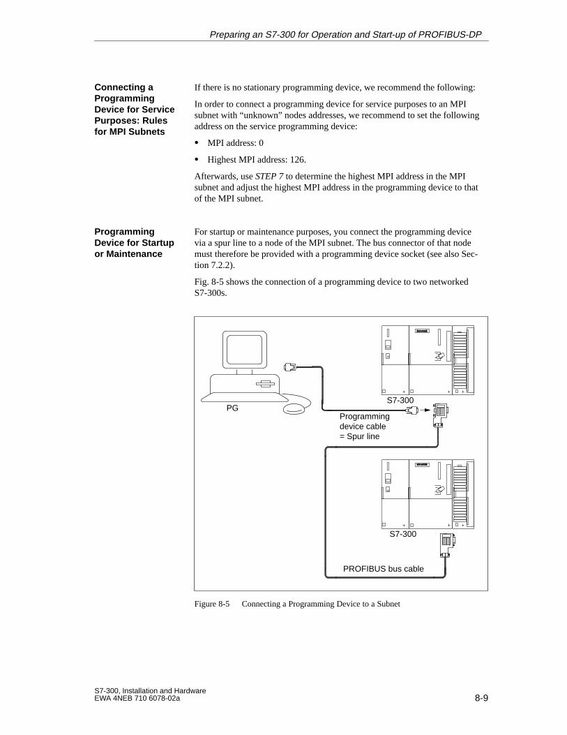
8-9S7-300, Installation and HardwareEWA 4NEB 710 6078-02a
If there is no stationary programming device, we recommend the following:
In order to connect a programming device for service purposes to an MPIsubnet with “unknown” nodes addresses, we recommend to set the followingaddress on the service programming device:
MPI address: 0
Highest MPI address: 126.
Afterwards, use STEP 7 to determine the highest MPI address in the MPIsubnet and adjust the highest MPI address in the programming device to thatof the MPI subnet.
For startup or maintenance purposes, you connect the programming devicevia a spur line to a node of the MPI subnet. The bus connector of that nodemust therefore be provided with a programming device socket (see also Sec-tion 7.2.2).
Fig. 8-5 shows the connection of a programming device to two networkedS7-300s.
PROFIBUS bus cable
Programmingdevice cable = Spur line
S7-300
S7-300
PG
Figure 8-5 Connecting a Programming Device to a Subnet
Connecting a Programming Device for ServicePurposes: Rulesfor MPI Subnets
Programming Device for Startupor Maintenance
Preparing an S7-300 for Operation and Start-up of PROFIBUS-DP
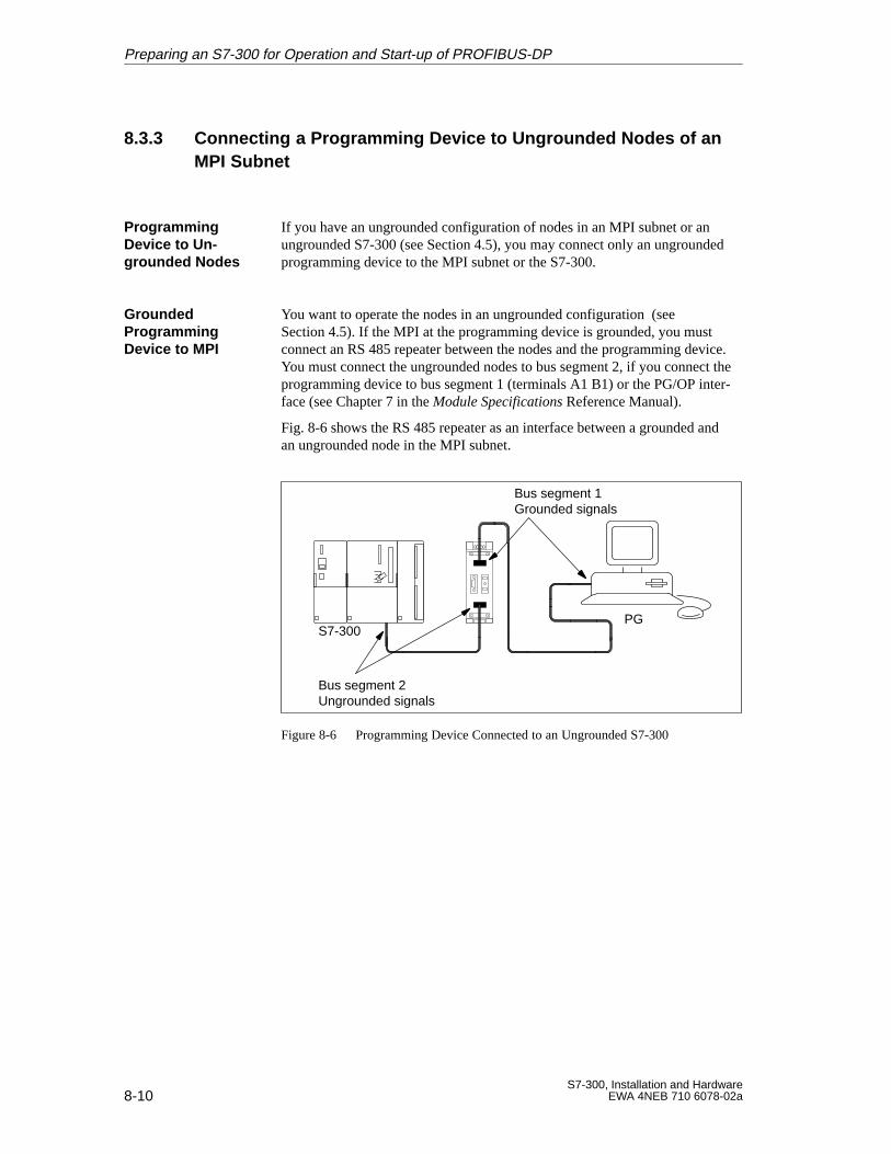
8-10S7-300, Installation and Hardware
EWA 4NEB 710 6078-02a
8.3.3 Connecting a Programming Device to Ungrounded Nodes of an MPI Subnet
If you have an ungrounded configuration of nodes in an MPI subnet or anungrounded S7-300 (see Section 4.5), you may connect only an ungroundedprogramming device to the MPI subnet or the S7-300.
You want to operate the nodes in an ungrounded configuration (seeSection 4.5). If the MPI at the programming device is grounded, you mustconnect an RS 485 repeater between the nodes and the programming device.You must connect the ungrounded nodes to bus segment 2, if you connect theprogramming device to bus segment 1 (terminals A1 B1) or the PG/OP inter-face (see Chapter 7 in the Module Specifications Reference Manual).
Fig. 8-6 shows the RS 485 repeater as an interface between a grounded andan ungrounded node in the MPI subnet.
S7-300
Bus segment 2Ungrounded signals
PG
Bus segment 1Grounded signals
Figure 8-6 Programming Device Connected to an Ungrounded S7-300
Programming Device to Un -grounded Nodes
Grounded Programming Device to MPI
Preparing an S7-300 for Operation and Start-up of PROFIBUS-DP
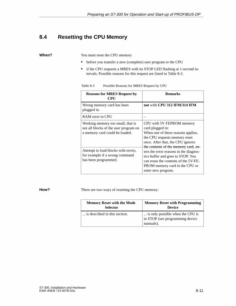
8-11S7-300, Installation and HardwareEWA 4NEB 710 6078-02a
8.4 Resetting the CPU Memory
You must reset the CPU memory
before you transfer a new (complete) user program to the CPU
if the CPU requests a MRES with its STOP LED flashing at 1-second in-tervals. Possible reasons for this request are listed in Table 8-3.
Table 8-3 Possible Reasons for MRES Request by CPU
Reasons for MRES Request byCPU
Remarks
Wrong memory card has beenplugged in.
not with CPU 312 IFM/314 IFM
RAM error in CPU –
Working memory too small, that isnot all blocks of the user program ona memory card could be loaded.
CPU with 5V FEPROM memorycard plugged in:When one of these reasons applies,the CPU requests memory resetonce. After that, the CPU ignoresthe contents of the memory card en-
Attempt to load blocks with errors,for example if a wrong commandhas been programmed.
the contents of the memory card, en-ters the error reasons in the diagnos-tics buffer and goes to STOP. Youcan erase the contents of the 5V-FE-PROM memory card in the CPU orenter new program.
There are two ways of resetting the CPU memory:
Memory Reset with the Mode Selector
Memory Reset with ProgrammingDevice
... is described in this section. ... is only possible when the CPU isin STOP (see programming devicemanuals).
When?
How?
Preparing an S7-300 for Operation and Start-up of PROFIBUS-DP

8-12S7-300, Installation and Hardware
EWA 4NEB 710 6078-02a
To reset the CPU memory using the mode selector, do the following (also seeFig. 8-7):
1. Turn the key to the STOP position.
2. Turn the key to the MRES position. Hold the key in this position until theSTOP LED lights up for the second time (this takes 3 seconds).
The CPU acknowledges the reset request.
3. Within 3 seconds, you must turn the key back to the MRES position andhold it in this position until the STOP-LED flashes (at 2 Hz). When theCPU has completed the reset, the STOP LED stops flashing and remainslit.
The CPU has performed the reset.
t
On
Off 3 s
max. 3 s
min. 3 s
STOPLED
Figure 8-7 Switching Sequence for the Mode Selector for Resetting the CPU
If the STOP LED does not flash on reset or if another LED flashes (otherthan the BATF LED), you must repeat steps 2 and 3. If the CPU does not per-form the reset this time, evaluate the diagnostics buffer of the CPU.
Resetting the CPUMemory Using theMode Selector
STOP LED Doesnot Flash on Re-set?
Preparing an S7-300 for Operation and Start-up of PROFIBUS-DP
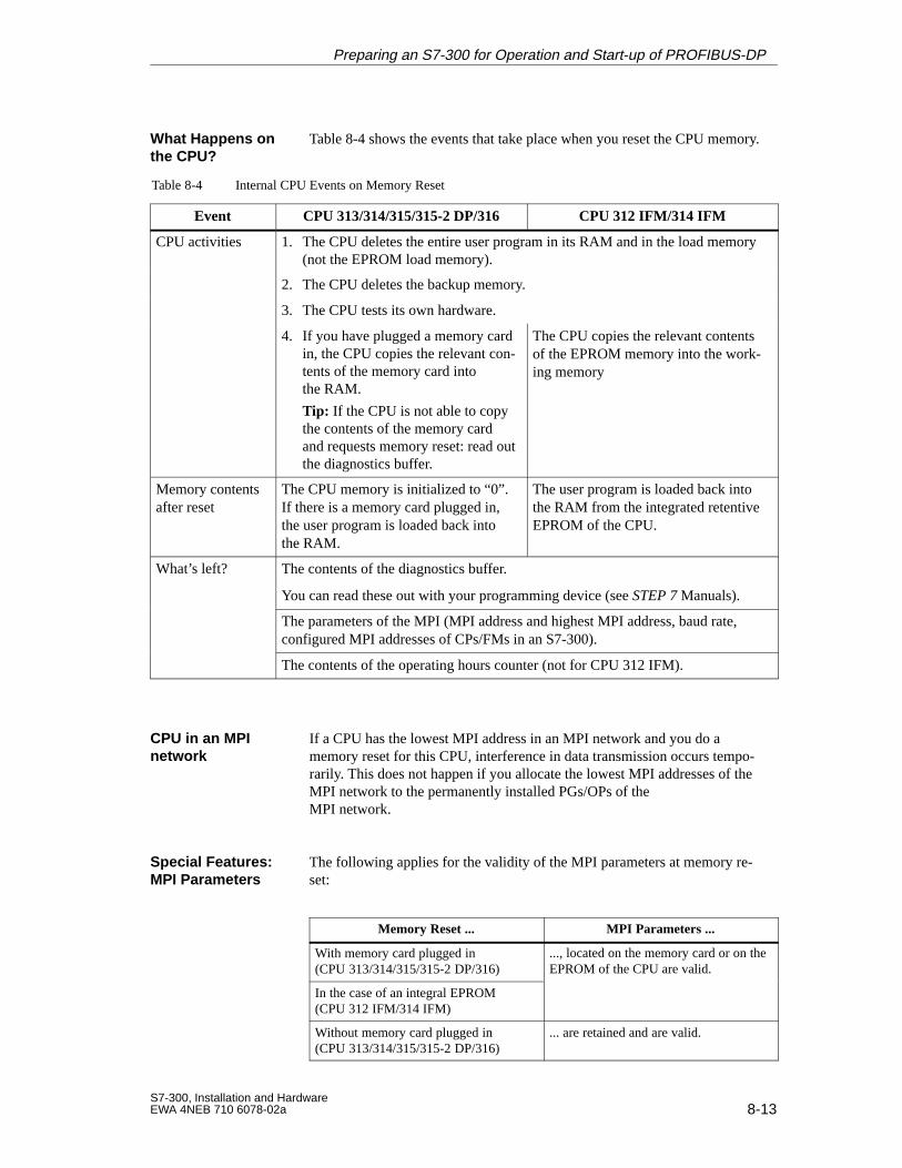
8-13S7-300, Installation and HardwareEWA 4NEB 710 6078-02a
Table 8-4 shows the events that take place when you reset the CPU memory.
Table 8-4 Internal CPU Events on Memory Reset
Event CPU 313/314/315/315-2 DP/316 CPU 312 IFM/314 IFM
CPU activities 1. The CPU deletes the entire user program in its RAM and in the load memory(not the EPROM load memory).
2. The CPU deletes the backup memory.
3. The CPU tests its own hardware.
4. If you have plugged a memory cardin, the CPU copies the relevant con-tents of the memory card intothe RAM.
Tip: If the CPU is not able to copythe contents of the memory cardand requests memory reset: read outthe diagnostics buffer.
The CPU copies the relevant contentsof the EPROM memory into the work-ing memory
Memory contentsafter reset
The CPU memory is initialized to “0”.If there is a memory card plugged in,the user program is loaded back intothe RAM.
The user program is loaded back intothe RAM from the integrated retentiveEPROM of the CPU.
What’s left? The contents of the diagnostics buffer.
You can read these out with your programming device (see STEP 7 Manuals).
The parameters of the MPI (MPI address and highest MPI address, baud rate,configured MPI addresses of CPs/FMs in an S7-300).
The contents of the operating hours counter (not for CPU 312 IFM).
If a CPU has the lowest MPI address in an MPI network and you do amemory reset for this CPU, interference in data transmission occurs tempo-rarily. This does not happen if you allocate the lowest MPI addresses of theMPI network to the permanently installed PGs/OPs of the MPI network.
The following applies for the validity of the MPI parameters at memory re-set:
Memory Reset ... MPI Parameters ...
With memory card plugged in(CPU 313/314/315/315-2 DP/316)
..., located on the memory card or on theEPROM of the CPU are valid.
In the case of an integral EPROM(CPU 312 IFM/314 IFM)
Without memory card plugged in(CPU 313/314/315/315-2 DP/316)
... are retained and are valid.
What Happens onthe CPU?
CPU in an MPI network
Special Features:MPI Parameters
Preparing an S7-300 for Operation and Start-up of PROFIBUS-DP
8-14S7-300, Installation and Hardware
EWA 4NEB 710 6078-02a
8.5 PROFIBUS-DP Startup
This section describes how to proceed if you want to start up a PROFIBUSsubnet with a CPU 315-2 DP.
Section Contents Page
8.5.1 Startup of the CPU 315-2 DP as a DP Master 8-15
8.5.2 Startup of the CPU 315-2 DP as a DP Slave 8-16
Before you can start up the PROFIBUS subnet, you must perform the follow-ing actions:
Set up the PROFIBUS subnet (see Chapter 7).
Configure the PROFIBUS subnet with STEP 7 and allocate a PROFIBUSaddress and the address area (see the STEP 7 User Manual). Please notethat the PROFIBUS address switch must be set on some DP slaves (seethe description for the DP slave).
In this Section
Requirements
Preparing an S7-300 for Operation and Start-up of PROFIBUS-DP
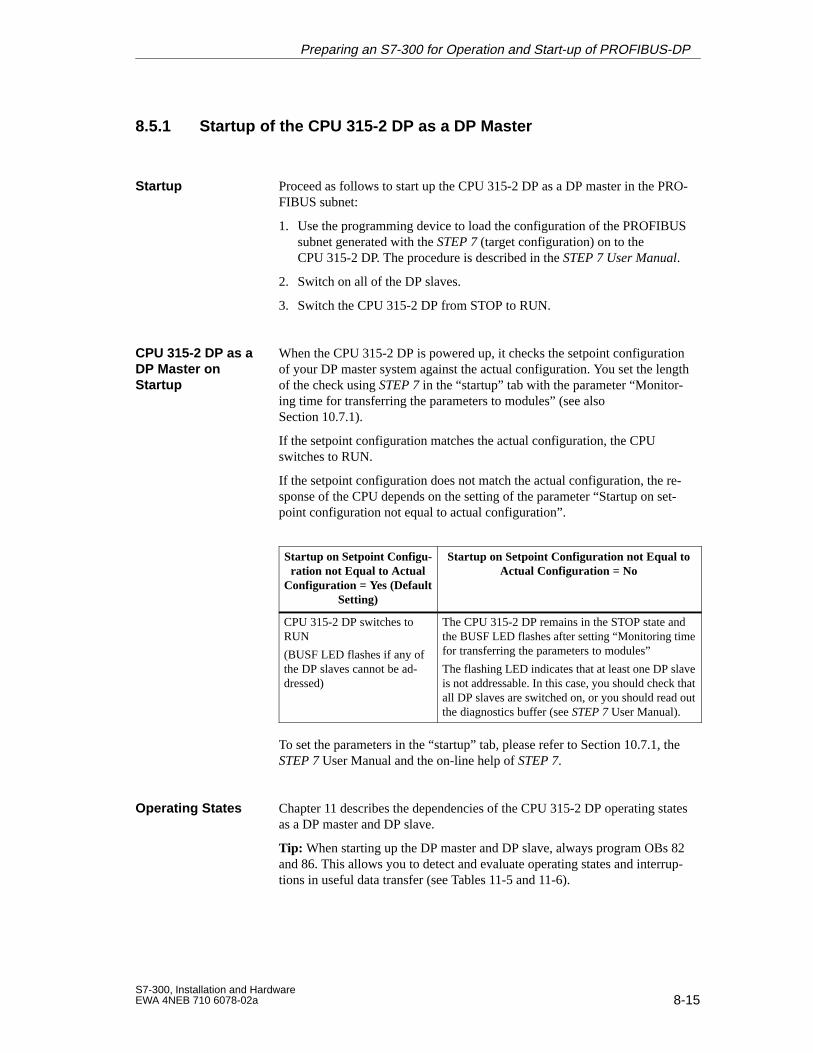
8-15S7-300, Installation and HardwareEWA 4NEB 710 6078-02a
8.5.1 Startup of the CPU 315-2 DP as a DP Master
Proceed as follows to start up the CPU 315-2 DP as a DP master in the PRO-FIBUS subnet:
1. Use the programming device to load the configuration of the PROFIBUSsubnet generated with the STEP 7 (target configuration) on to theCPU 315-2 DP. The procedure is described in the STEP 7 User Manual.
2. Switch on all of the DP slaves.
3. Switch the CPU 315-2 DP from STOP to RUN.
When the CPU 315-2 DP is powered up, it checks the setpoint configurationof your DP master system against the actual configuration. You set the lengthof the check using STEP 7 in the “startup” tab with the parameter “Monitor-ing time for transferring the parameters to modules” (see alsoSection 10.7.1).
If the setpoint configuration matches the actual configuration, the CPUswitches to RUN.
If the setpoint configuration does not match the actual configuration, the re-sponse of the CPU depends on the setting of the parameter “Startup on set-point configuration not equal to actual configuration”.
Startup on Setpoint Configu-ration not Equal to Actual
Configuration = Yes (DefaultSetting)
Startup on Setpoint Configuration not Equal toActual Configuration = No
CPU 315-2 DP switches toRUN
(BUSF LED flashes if any ofthe DP slaves cannot be ad-dressed)
The CPU 315-2 DP remains in the STOP state andthe BUSF LED flashes after setting “Monitoring timefor transferring the parameters to modules”
The flashing LED indicates that at least one DP slaveis not addressable. In this case, you should check thatall DP slaves are switched on, or you should read outthe diagnostics buffer (see STEP 7 User Manual).
To set the parameters in the “startup” tab, please refer to Section 10.7.1, theSTEP 7 User Manual and the on-line help of STEP 7.
Chapter 11 describes the dependencies of the CPU 315-2 DP operating statesas a DP master and DP slave.
Tip: When starting up the DP master and DP slave, always program OBs 82and 86. This allows you to detect and evaluate operating states and interrup-tions in useful data transfer (see Tables 11-5 and 11-6).
Startup
CPU 315-2 DP as aDP Master onStartup
Operating States
Preparing an S7-300 for Operation and Start-up of PROFIBUS-DP
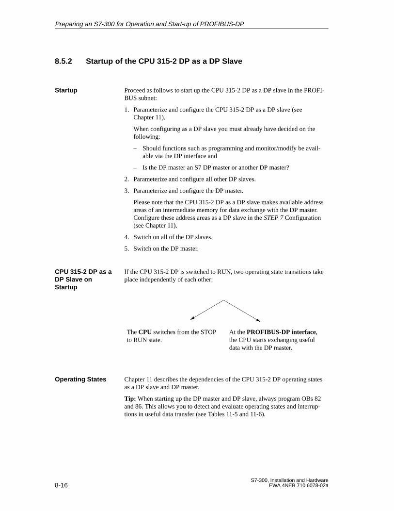
8-16S7-300, Installation and Hardware
EWA 4NEB 710 6078-02a
8.5.2 Startup of the CPU 315-2 DP as a DP Slave
Proceed as follows to start up the CPU 315-2 DP as a DP slave in the PROFI-BUS subnet:
1. Parameterize and configure the CPU 315-2 DP as a DP slave (seeChapter 11).
When configuring as a DP slave you must already have decided on thefollowing:
– Should functions such as programming and monitor/modify be avail-able via the DP interface and
– Is the DP master an S7 DP master or another DP master?
2. Parameterize and configure all other DP slaves.
3. Parameterize and configure the DP master.
Please note that the CPU 315-2 DP as a DP slave makes available addressareas of an intermediate memory for data exchange with the DP master.Configure these address areas as a DP slave in the STEP 7 Configuration(see Chapter 11).
4. Switch on all of the DP slaves.
5. Switch on the DP master.
If the CPU 315-2 DP is switched to RUN, two operating state transitions takeplace independently of each other:
The CPU switches from the STOPto RUN state.
At the PROFIBUS-DP interface,the CPU starts exchanging usefuldata with the DP master.
Chapter 11 describes the dependencies of the CPU 315-2 DP operating statesas a DP slave and DP master.
Tip: When starting up the DP master and DP slave, always program OBs 82and 86. This allows you to detect and evaluate operating states and interrup-tions in useful data transfer (see Tables 11-5 and 11-6).
Startup
CPU 315-2 DP as aDP Slave onStartup
Operating States
Preparing an S7-300 for Operation and Start-up of PROFIBUS-DP
9-1S7-300, Installation and HardwareEWA 4NEB 710 6078-02a
Changing the Backup Battery/Recharg-able Battery, Module and Fuses
In this chapter, you will learn
how to change the backup battery or rechargeable battery
how to dispose of the backup battery
how to replace the modules of the S7-300
how to replace the fuses of digital output modules and which replacementfuses you must use.
The sections in this chapter describe the following:
Section Contents Page
9.1 Changing the Backup Battery/Rechargeable Battery (notCPU 312 IFM)
9-2
9.2 Replacing Modules 9-4
9.3 Replacing Fuses on 120/230 VAC Digital Output Modules 9-8
Chapter Contents
In this Chapter
9
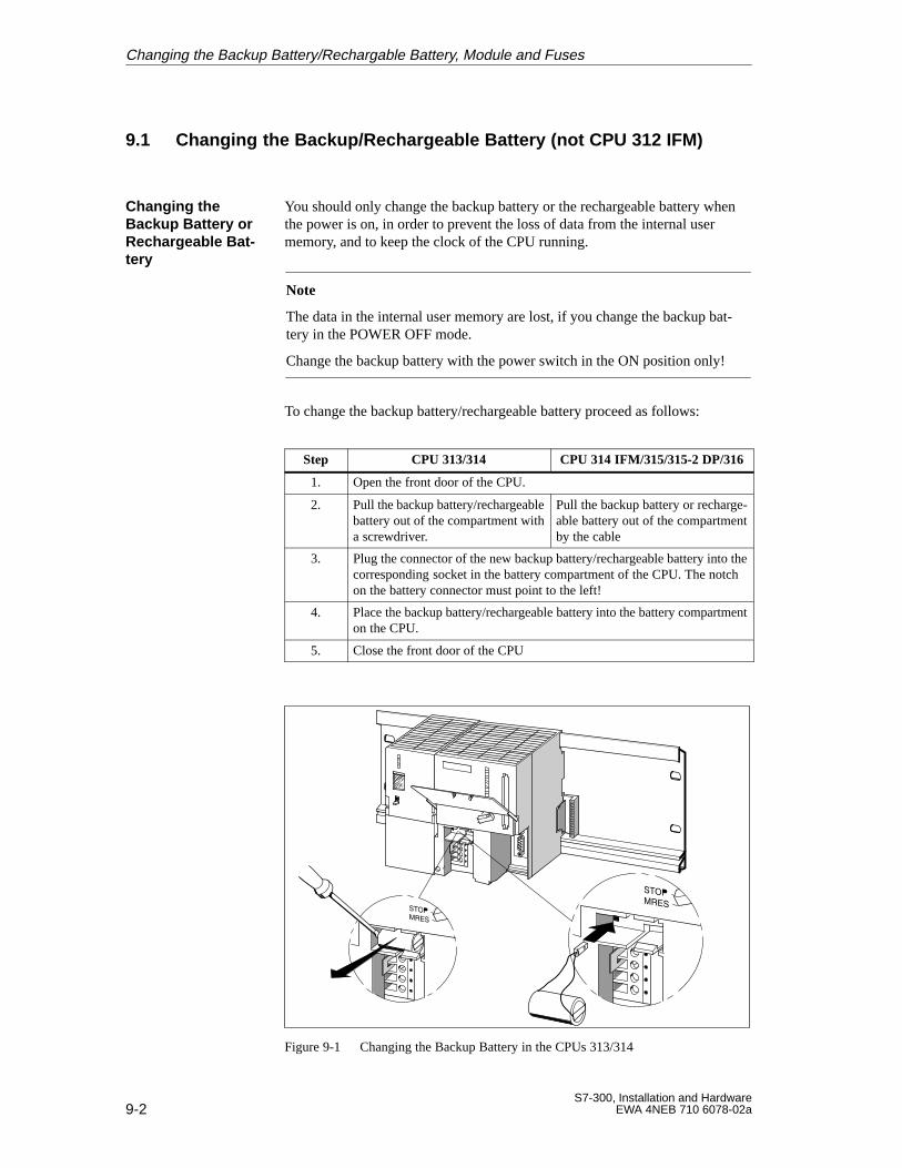
9-2S7-300, Installation and Hardware
EWA 4NEB 710 6078-02a
9.1 Changing the Backup/Rechargeable Battery (not CPU 312 IFM)
You should only change the backup battery or the rechargeable battery whenthe power is on, in order to prevent the loss of data from the internal usermemory, and to keep the clock of the CPU running.
Note
The data in the internal user memory are lost, if you change the backup bat-tery in the POWER OFF mode.
Change the backup battery with the power switch in the ON position only!
To change the backup battery/rechargeable battery proceed as follows:
Step CPU 313/314 CPU 314 IFM/315/315-2 DP/316
1. Open the front door of the CPU.
2. Pull the backup battery/rechargeablebattery out of the compartment witha screwdriver.
Pull the backup battery or recharge-able battery out of the compartmentby the cable
3. Plug the connector of the new backup battery/rechargeable battery into thecorresponding socket in the battery compartment of the CPU. The notchon the battery connector must point to the left!
4. Place the backup battery/rechargeable battery into the battery compartmenton the CPU.
5. Close the front door of the CPU
Figure 9-1 Changing the Backup Battery in the CPUs 313/314
Changing theBackup Battery orRechargeable Bat -tery
Changing the Backup Battery/Rechargable Battery, Module and Fuses
9-3S7-300, Installation and HardwareEWA 4NEB 710 6078-02a
Backup battery: We recommend that you replace the backup battery atyearly intervals.
Rechargeable battery: It is not necessary to replace the rechargeable bat-tery.
Backup batteries must be disposed of in keeping with the relevant nationalenvironment protection regulations/guidelines.
Store backup batteries in a dry and cool place.
Backup batteries can be stored for five years.
!Warning
If backup batteries are not treated properly, they can ignite, explode andcause severe burning.
Store backup batteries in a dry and cool place.
To reduce the risk of danger when handling backup batteries, you must ob-serve the following rules:
!Warning
Improper handling of backup batteries can cause injuries and property dam-age.
Backup batteries that are not handled properly can explode and cause severeburns.
Do not
recharge
overheat
burn
puncture
crush
short-circuit backup batteries!
You must not charge the rechargeable battery when not inserted in the CPU!Charge rechargeable battery only via CPU when power is switched on.
How Often?
Disposal of theOld Battery
Storing BackupBatteries
Rules Governingthe Handling ofBackup Batteries
Rules Governingthe Handling ofRechargeable Bat -teries
Changing the Backup Battery/Rechargable Battery, Module and Fuses
9-4S7-300, Installation and Hardware
EWA 4NEB 710 6078-02a
9.2 Replacing Modules
The following table tells you what you have to do when wiring, detachingand installing the S7-300 modules.
Rules Governing ... Power Supply
... CPU ... SM/FM/CP
Blade width of screwdriver 3.5 mm (cylindrical model)
Tightening torque
Attaching modules to the rail 0.8 toto 1.1 Nm
0.8 toto 1.1 Nm
Terminating cables 0.5 to0.8 Nm
–
POWER OFF when replac-ing the ...
Yes No
Operating mode of S7-300when replacing the ...
– STOP
Load voltage OFF when re-placing the ...
Yes Yes
The module you want to replace is installed and wired. You want to install anew module of the same type.
!Warning
If you remove or plug in the S7-300 modules during data transmission viathe MPI, the data might be corrupted by disturbing pulses.
You must not plug in or remove any S7-300 modules during data transmis-sion via the MPI!
If you are not sure whether any communications activities are taking place,pull the connector out of the MPI port.
Rules GoverningWiring and Instal-lation
Situation
Changing the Backup Battery/Rechargable Battery, Module and Fuses
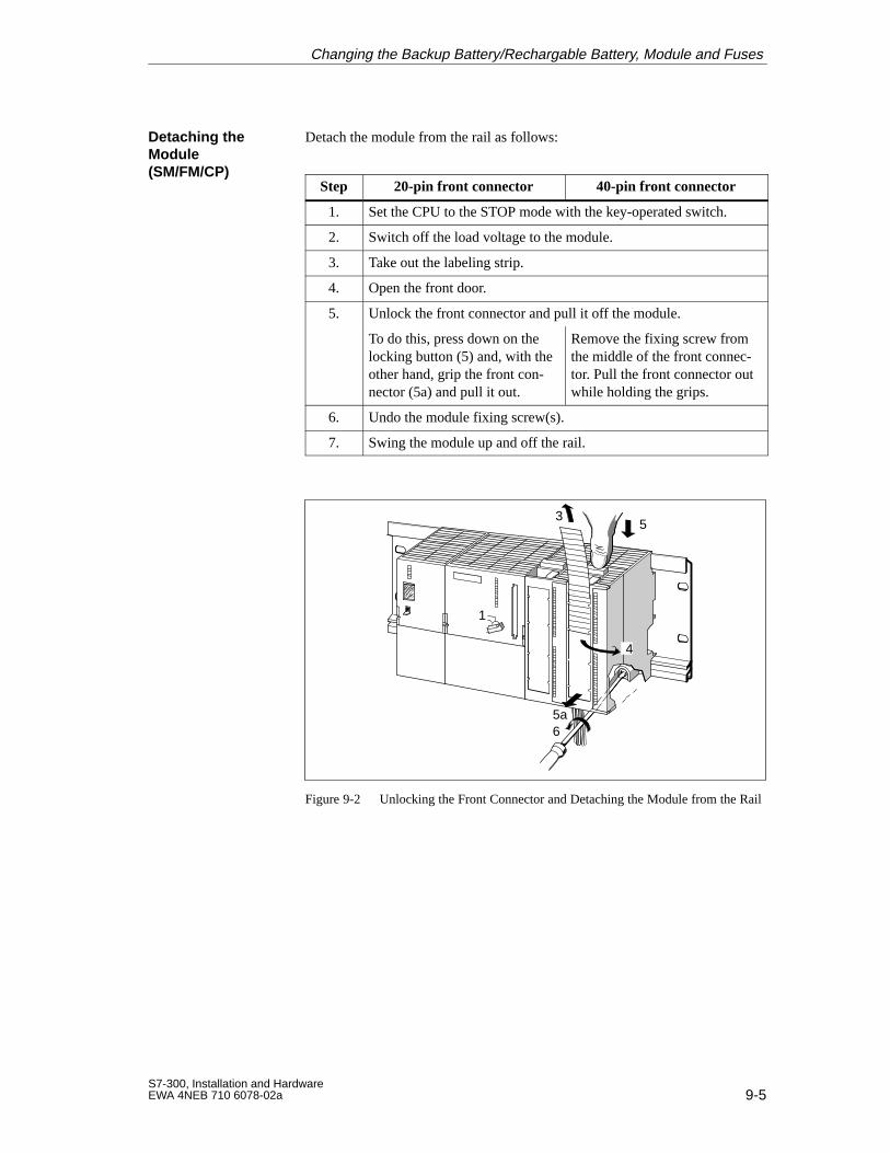
9-5S7-300, Installation and HardwareEWA 4NEB 710 6078-02a
Detach the module from the rail as follows:
Step 20-pin front connector 40-pin front connector
1. Set the CPU to the STOP mode with the key-operated switch.
2. Switch off the load voltage to the module.
3. Take out the labeling strip.
4. Open the front door.
5. Unlock the front connector and pull it off the module.
To do this, press down on thelocking button (5) and, with theother hand, grip the front con-nector (5a) and pull it out.
Remove the fixing screw fromthe middle of the front connec-tor. Pull the front connector outwhile holding the grips.
6. Undo the module fixing screw(s).
7. Swing the module up and off the rail.
1
35
4
65a
Figure 9-2 Unlocking the Front Connector and Detaching the Module from the Rail
Detaching theModule (SM/FM/CP)
Changing the Backup Battery/Rechargable Battery, Module and Fuses
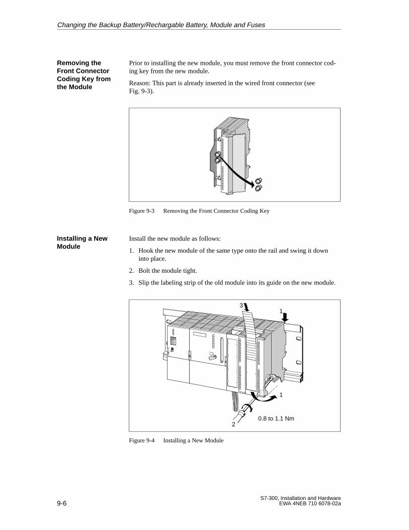
9-6S7-300, Installation and Hardware
EWA 4NEB 710 6078-02a
Prior to installing the new module, you must remove the front connector cod-ing key from the new module.
Reason: This part is already inserted in the wired front connector (seeFig. 9-3).
Figure 9-3 Removing the Front Connector Coding Key
Install the new module as follows:
1. Hook the new module of the same type onto the rail and swing it downinto place.
2. Bolt the module tight.
3. Slip the labeling strip of the old module into its guide on the new module.
0.8 to 1.1 Nm
1
2
13
Figure 9-4 Installing a New Module
Removing theFront ConnectorCoding Key fromthe Module
Installing a NewModule
Changing the Backup Battery/Rechargable Battery, Module and Fuses
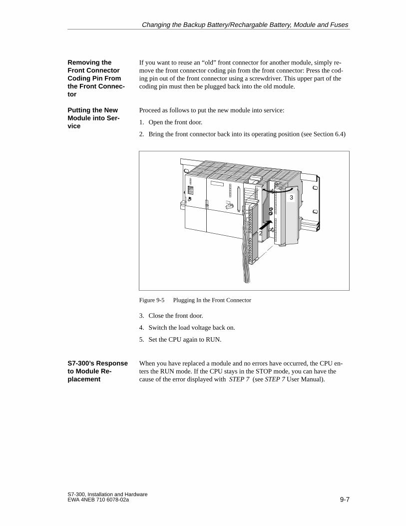
9-7S7-300, Installation and HardwareEWA 4NEB 710 6078-02a
If you want to reuse an “old” front connector for another module, simply re-move the front connector coding pin from the front connector: Press the cod-ing pin out of the front connector using a screwdriver. This upper part of thecoding pin must then be plugged back into the old module.
Proceed as follows to put the new module into service:
1. Open the front door.
2. Bring the front connector back into its operating position (see Section 6.4)
3
2
Figure 9-5 Plugging In the Front Connector
3. Close the front door.
4. Switch the load voltage back on.
5. Set the CPU again to RUN.
When you have replaced a module and no errors have occurred, the CPU en-ters the RUN mode. If the CPU stays in the STOP mode, you can have thecause of the error displayed with STEP 7 (see STEP 7 User Manual).
Removing theFront ConnectorCoding Pin Fromthe Front Connec-tor
Putting the NewModule into Ser -vice
S7-300’s Responseto Module Re-placement
Changing the Backup Battery/Rechargable Battery, Module and Fuses
9-8S7-300, Installation and Hardware
EWA 4NEB 710 6078-02a
9.3 Replacing Fuses on 120/230 VAC Digital Output Modules
Fuses are used for the individual channel groups of the digital outputs of thefollowing digital output modules, to protect these against short circuit:
Digital output module SM 322; DO 16 120 VAC
Digital output module SM 322; DO 8 120/230 VAC
If you have to change fuses, you can use, for example, the following sparefuses:
8 A, 250 V fuse
– Wickmann 19 194-8 A
– Schurter SP001.013
– Littlefuse 217.008
Fuse holder
– Wickmann 19 653
Fuses for DigitalOutputs
Spare Fuses
Changing the Backup Battery/Rechargable Battery, Module and Fuses
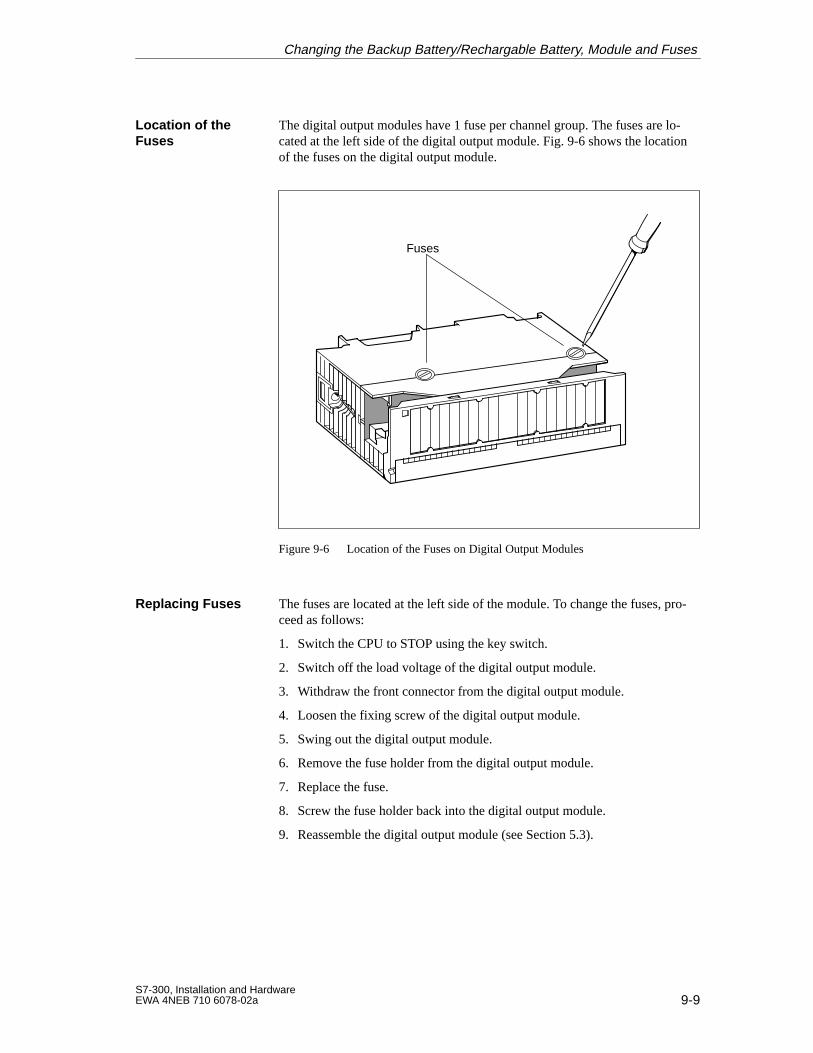
9-9S7-300, Installation and HardwareEWA 4NEB 710 6078-02a
The digital output modules have 1 fuse per channel group. The fuses are lo-cated at the left side of the digital output module. Fig. 9-6 shows the locationof the fuses on the digital output module.
Fuses
Figure 9-6 Location of the Fuses on Digital Output Modules
The fuses are located at the left side of the module. To change the fuses, pro-ceed as follows:
1. Switch the CPU to STOP using the key switch.
2. Switch off the load voltage of the digital output module.
3. Withdraw the front connector from the digital output module.
4. Loosen the fixing screw of the digital output module.
5. Swing out the digital output module.
6. Remove the fuse holder from the digital output module.
7. Replace the fuse.
8. Screw the fuse holder back into the digital output module.
9. Reassemble the digital output module (see Section 5.3).
Location of theFuses
Replacing Fuses
Changing the Backup Battery/Rechargable Battery, Module and Fuses

9-10S7-300, Installation and Hardware
EWA 4NEB 710 6078-02a
Changing the Backup Battery/Rechargable Battery, Module and Fuses
10-1S7-300, Installation and HardwareEWA 4NEB 710 6078-02a
CPUs
This chapter describes the CPUs of the S7-300 programmable controller.
The CPUs differ in performance and functionality but they are operated inexactly the same manner.
The tables in Section 10.1 summarize the performance characteristics of theCPUs. The common characteristics of the CPUs are described in Sections10.2 to 10.7.
The specific characteristics and the technical specifications of the individualCPUs are described in Section 10.8.
If you are using the CPU 315-2 DP as a DP master or DP slave, you mustalso read Chapter 11. Here you will find the CPU data and characteristicsrelevant to PROFIBUS DP.
How to insert the memory card, the backup battery and the rechargeable bat-tery and how to reset the CPU is described in Chapter 8.
Section Contents Page
10.1 Performance Characteristics 10-2
10.2 Mode Selector, LEDs and Test Functions 10-5
10.3 Connection of the Power Supply Unit 10-9
10.4 Multipoint Interface (MPI) 10-10
10.5 Clock and Operating Hours Counter 10-13
10.6 Blocks 10-15
10.7 Parameters 10-19
10.8 CPUs – Technical Specifications 10-35
Introduction
In this Chapter
10
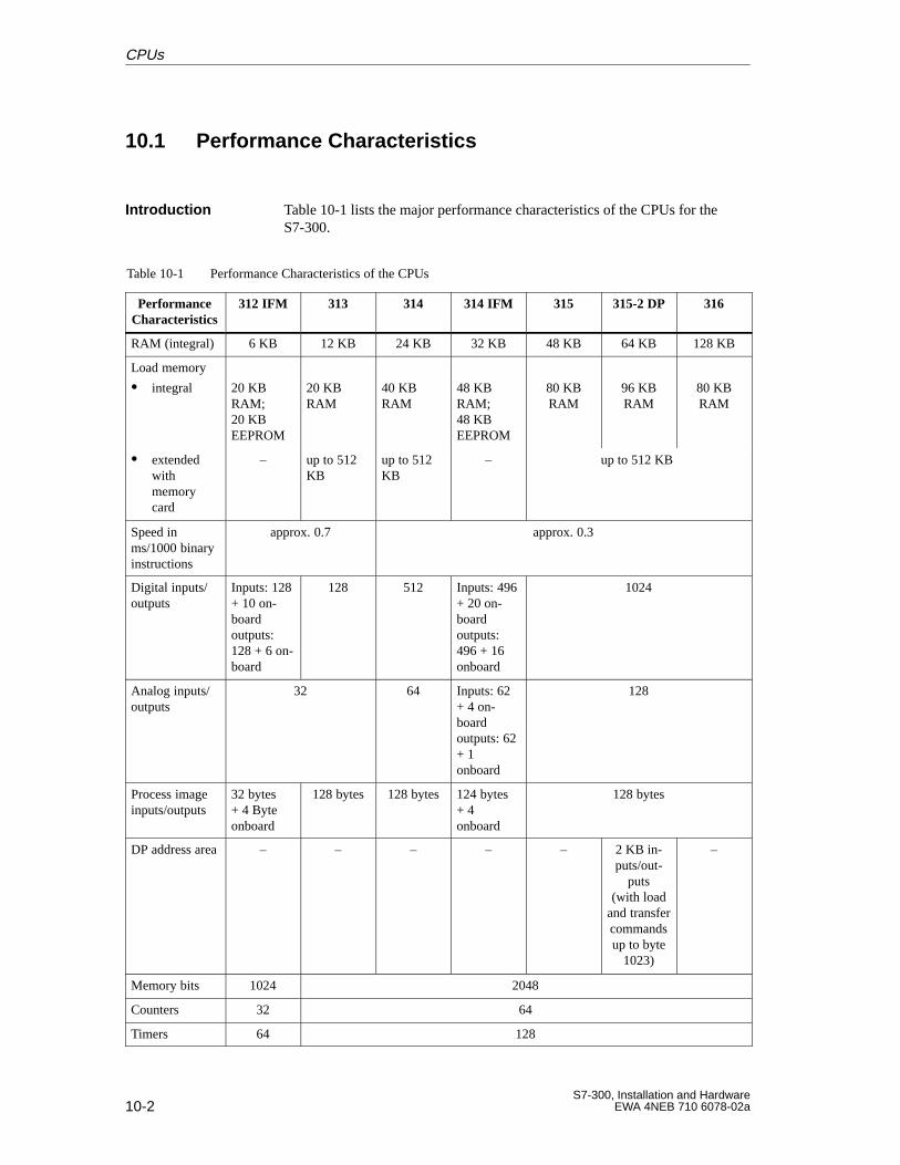
10-2S7-300, Installation and Hardware
EWA 4NEB 710 6078-02a
10.1 Performance Characteristics
Table 10-1 lists the major performance characteristics of the CPUs for theS7-300.
Table 10-1 Performance Characteristics of the CPUs
PerformanceCharacteristics
312 IFM 313 314 314 IFM 315 315-2 DP 316
RAM (integral) 6 KB 12 KB 24 KB 32 KB 48 KB 64 KB 128 KB
Load memory
integral 20 KBRAM;20 KB EEPROM
20 KBRAM
40 KBRAM
48 KBRAM;48 KB EEPROM
80 KBRAM
96 KBRAM
80 KBRAM
extendedwithmemorycard
– up to 512KB
up to 512KB
– up to 512 KB
Speed inms/1000 binaryinstructions
approx. 0.7 approx. 0.3
Digital inputs/outputs
Inputs: 128+ 10 on-boardoutputs:128 + 6 on-board
128 512 Inputs: 496+ 20 on-boardoutputs:496 + 16onboard
1024
Analog inputs/outputs
32 64 Inputs: 62+ 4 on-boardoutputs: 62+ 1 onboard
128
Process imageinputs/outputs
32 bytes+ 4 Byteonboard
128 bytes 128 bytes 124 bytes+ 4 onboard
128 bytes
DP address area – – – – – 2 KB in-puts/out-
puts(with load
and transfercommandsup to byte
1023)
–
Memory bits 1024 2048
Counters 32 64
Timers 64 128
Introduction
CPUs
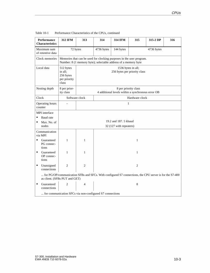
10-3S7-300, Installation and HardwareEWA 4NEB 710 6078-02a
Table 10-1 Performance Characteristics of the CPUs, continued
PerformanceCharacteristics
316315-2 DP315314 IFM314313312 IFM
Maximum sumof retentive data
72 bytes 4736 bytes 144 bytes 4736 bytes
Clock memories Memories that can be used for clocking purposes in the user program.Number: 8 (1 memory byte); selectable address of a memory byte
Local data 512 bytesin all;256 bytesper priorityclass
1536 bytes in all;256 bytes per priority class
Nesting depth 8 per prior-ity class
8 per priority class4 additional levels within a synchronous error OB
Clock Software clock Hardware clock
Operating hourscounter
– 1
MPI interface
Baud rate
Max. No. ofnodes
19.2 and 187. 5 kbaud
32 (127 with repeaters)
Communicationvia MPI
GuaranteedPG connec-tions
GuaranteedOP connec-tions
1
1
1
1
1
1
Unassignedconnections
2 2 2
... for PG/OP/communication SFBs and SFCs. With configured S7 connections, the CPU server is for the S7-400as client. (SFBs PUT and GET)
Guaranteedconnections
2 4 8
... for communication SFCs via non-configured S7 connections
CPUs
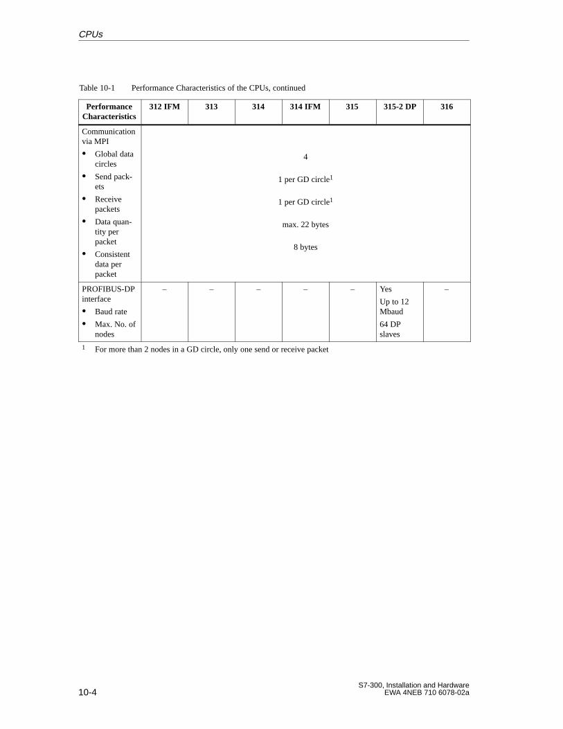
10-4S7-300, Installation and Hardware
EWA 4NEB 710 6078-02a
Table 10-1 Performance Characteristics of the CPUs, continued
PerformanceCharacteristics
316315-2 DP315314 IFM314313312 IFM
Communicationvia MPI
Global datacircles
Send pack-ets
Receivepackets
Data quan-tity per packet
Consistentdata perpacket
4
1 per GD circle1
1 per GD circle1
max. 22 bytes
8 bytes
PROFIBUS-DPinterface
Baud rate
Max. No. ofnodes
– – – – – Yes
Up to 12Mbaud
64 DPslaves
–
1 For more than 2 nodes in a GD circle, only one send or receive packet
CPUs
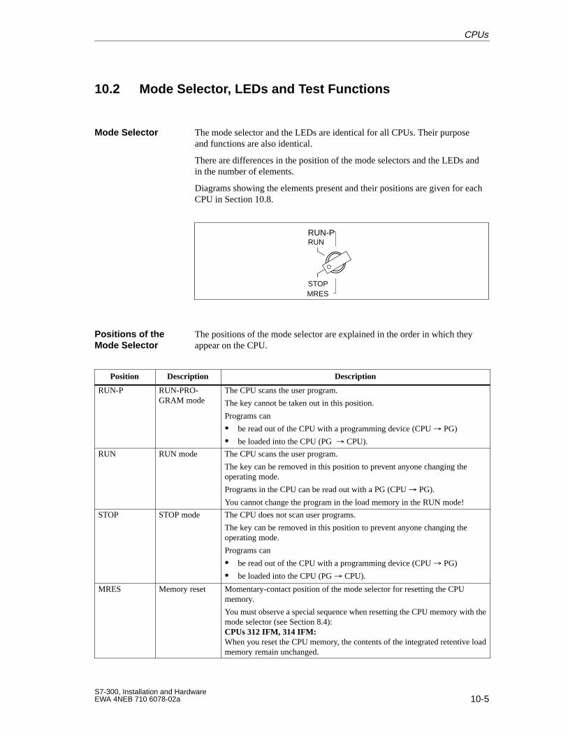
10-5S7-300, Installation and HardwareEWA 4NEB 710 6078-02a
10.2 Mode Selector , LEDs and T est Functions
The mode selector and the LEDs are identical for all CPUs. Their purposeand functions are also identical.
There are differences in the position of the mode selectors and the LEDs andin the number of elements.
Diagrams showing the elements present and their positions are given for eachCPU in Section 10.8.
MRESSTOP
RUNRUN-P
The positions of the mode selector are explained in the order in which theyappear on the CPU.
Position Description Description
RUN-P RUN-PRO-GRAM mode
The CPU scans the user program.
The key cannot be taken out in this position.
Programs can
be read out of the CPU with a programming device (CPU PG)
be loaded into the CPU (PG CPU).
RUN RUN mode The CPU scans the user program.
The key can be removed in this position to prevent anyone changing the operating mode.
Programs in the CPU can be read out with a PG (CPU PG).
You cannot change the program in the load memory in the RUN mode!
STOP STOP mode The CPU does not scan user programs.
The key can be removed in this position to prevent anyone changing the operating mode.
Programs can
be read out of the CPU with a programming device (CPU PG)
be loaded into the CPU (PG CPU).
MRES Memory reset Momentary-contact position of the mode selector for resetting the CPUmemory.
You must observe a special sequence when resetting the CPU memory with themode selector (see Section 8.4):CPUs 312 IFM, 314 IFM:When you reset the CPU memory, the contents of the integrated retentive loadmemory remain unchanged.
Mode Selector
Positions of theMode Selector
CPUs
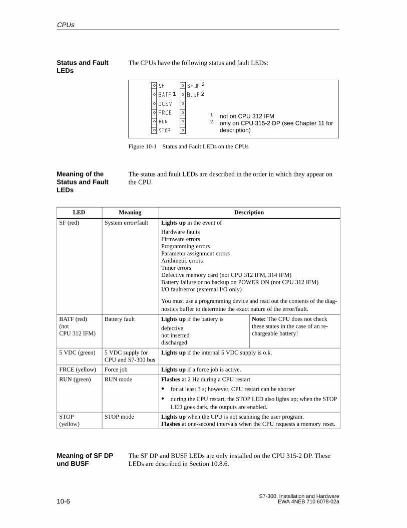
10-6S7-300, Installation and Hardware
EWA 4NEB 710 6078-02a
The CPUs have the following status and fault LEDs:
1
1 not on CPU 312 IFM2 only on CPU 315-2 DP (see Chapter 11 for
description)
2
2
Figure 10-1 Status and Fault LEDs on the CPUs
The status and fault LEDs are described in the order in which they appear onthe CPU.
LED Meaning Description
SF (red) System error/fault Lights up in the event of
Hardware faultsFirmware errorsProgramming errorsParameter assignment errorsArithmetic errorsTimer errorsDefective memory card (not CPU 312 IFM, 314 IFM)Battery failure or no backup on POWER ON (not CPU 312 IFM)I/O fault/error (external I/O only)
You must use a programming device and read out the contents of the diag-nostics buffer to determine the exact nature of the error/fault.
BATF (red)(notCPU 312 IFM)
Battery fault Lights up if the battery is
defectivenot inserteddischarged
Note: The CPU does not checkthese states in the case of an re-chargeable battery!
5 VDC (green) 5 VDC supply forCPU and S7-300 bus
Lights up if the internal 5 VDC supply is o.k.
FRCE (yellow) Force job Lights up if a force job is active.
RUN (green) RUN mode Flashes at 2 Hz during a CPU restart
for at least 3 s; however, CPU restart can be shorter
during the CPU restart, the STOP LED also lights up; when the STOPLED goes dark, the outputs are enabled.
STOP (yellow)
STOP mode Lights up when the CPU is not scanning the user program.Flashes at one-second intervals when the CPU requests a memory reset.
The SF DP and BUSF LEDs are only installed on the CPU 315-2 DP. TheseLEDs are described in Section 10.8.6.
Status and FaultLEDs
Meaning of theStatus and FaultLEDs
Meaning of SF DPund BUSF
CPUs
10-7S7-300, Installation and HardwareEWA 4NEB 710 6078-02a
The hardware and the operating system of the CPU provide you with variousmonitoring functions.
Any errors are indicated by the SF LED and the cause of error is written tothe diagnostics buffer. The CPU either goes into the STOP state or you canrespond in the user program to errors via error or interrupt OBs. The OBs thatcan be programmed for the individual CPUs are listed in Section 10.6.
Note
Please note that despite the extensive monitoring and error response func-tions provided, this is not a safety-oriented or fault-tolerant system.
With a series of test and reference data functions, the CPUs also offer you thepossibility to scan the status of the CPU and the corresponding signal mod-ules. You can thus obtain information on
the configuration of your S7-300
the parameters currently assigned
the current statuses and
the current sequences
in the CPU and the corresponding modules.
Independent of the user program you can also change process variables.
Table 10-2 contains the test functions of CPUs. See the STEP 7 User Manualfor an extensive description of the test functions.
Table 10-2 Test Functions of CPUs
Test Functions Application
Monitor variable Monitor selected process variables (inputs, outputs, bit memories, timers, counters, data) at aspecified point: Start/end of cycle, RUN STOP transition
Modify variable Assign a value to selected process variables (inputs, outputs, bit memories, data) at a specifiedpoint (Start/end of cycle, RUN STOP transition) and so force the user program.
Force Initialize up to 10 selected process variables with permanent values (on S7-300-CPUs onlyinputs and outputs in the process image) The force job remains active
when the connection is canceled
when the power is switched off if the CPU has a backup battery.
Status block Monitor a block with regard to the program sequence for support in start-up and trouble-shooting.
“Status block” offers the possibility to monitor certain register contents, such as rechargeablebatteries, address registers, status registers, DB registers, during instruction processing.
Set breakpoint Interrupt execution of the user program to perform a step–by–step test.
Monitoring Func-tions
List of Test Func-tions
CPUs
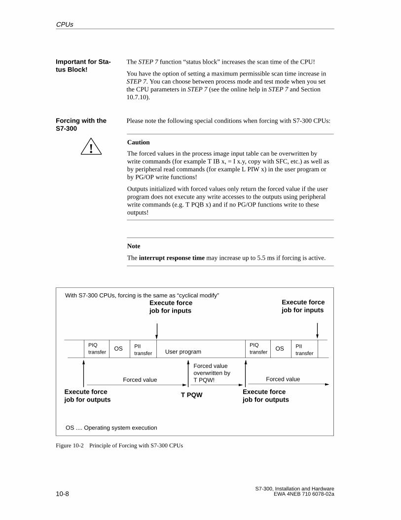
10-8S7-300, Installation and Hardware
EWA 4NEB 710 6078-02a
The STEP 7 function “status block” increases the scan time of the CPU!
You have the option of setting a maximum permissible scan time increase inSTEP 7. You can choose between process mode and test mode when you setthe CPU parameters in STEP 7 (see the online help in STEP 7 and Section10.7.10).
Please note the following special conditions when forcing with S7-300 CPUs:
!Caution
The forced values in the process image input table can be overwritten bywrite commands (for example T IB x, = I x.y, copy with SFC, etc.) as well asby peripheral read commands (for example L PIW x) in the user program orby PG/OP write functions!
Outputs initialized with forced values only return the forced value if the userprogram does not execute any write accesses to the outputs using peripheralwrite commands (e.g. T PQB x) and if no PG/OP functions write to theseoutputs!
Note
The interrupt r esponse time may increase up to 5.5 ms if forcing is active.
Execute forcejob for outputs
With S7-300 CPUs, forcing is the same as “cyclical modify”
PII transfer User programOS
T PQW
Forced valueoverwritten byT PQW!
Execute forcejob for inputs
Forced value
Execute forcejob for outputs
Forced value
Execute forcejob for inputs
OS .... Operating system execution
PIQtransfer
PII transfer
OSPIQtransfer
Figure 10-2 Principle of Forcing with S7-300 CPUs
Important for Sta -tus Block!
Forcing with theS7-300
CPUs
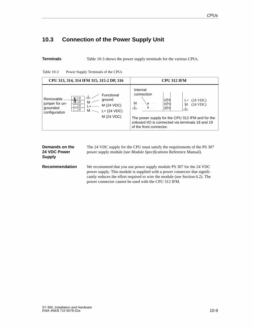
10-9S7-300, Installation and HardwareEWA 4NEB 710 6078-02a
10.3 Connection of the Power Supply Unit
Table 10-3 shows the power supply terminals for the various CPUs.
Table 10-3 Power Supply Terminals of the CPUs
CPU 313, 314, 314 IFM 315, 315-2 DP, 316 CPU 312 IFM
ML+M
Functionalground
M (24 VDC)
L+ (24 VDC)
M (24 VDC)
Removablejumper for un-groundedconfiguration
1 89
2 01
L+M
(24 VDC)(24 VDC)M
Internalconnection
The power supply for the CPU 312 IFM and for theonboard I/O is connected via terminals 18 and 19of the front connector.
The 24 VDC supply for the CPU must satisfy the requirements of the PS 307power supply module (see Module Specifications Reference Manual).
We recommend that you use power supply module PS 307 for the 24 VDCpower supply. This module is supplied with a power connector that signifi-cantly reduces the effort required to wire the module (see Section 6.2). Thepower connector cannot be used with the CPU 312 IFM.
Terminals
Demands on the24 VDC PowerSupply
Recommendation
CPUs
10-10S7-300, Installation and Hardware
EWA 4NEB 710 6078-02a
10.4 Multipoint Interface (MPI)
The multipoint interface (MPI) is the CPU port for the programming device/operator panel (PG/OP) or for communication with several nodes in an MPIsubnet (see also Chapter 7).
187.5 kbaud is the typical transmission rate for an MPI subnet.
You only need 19.2 kbaud if an S7–200 is connected to the MPI subnet.
Note
With 19.2 kbaud for communication with the S7-200:– up to 8 nodes (CPU, PG/OP, FM/CP with their own MPI address) are al-lowed in a subnet and– global data communication is not supported.
Please consult the S7-200 Manual for further information!
Please note that older CPU versions for the S7–300 programmable controllerdo not support the 19.2 kbaud transmission rate. Similarly, it is only possibleto set the 19.2 kbaud transmission rate with STEP 7 V 4.02 or higher.
You can interface the following devices over the MPI port:
Programming devices (PG/PC)
Operator panels (OPs)
Other S7-300 programmable controllers.
S7-200 programmable controllers
You can interconnect 32 nodes (programming devices, operator panels,S7-300s, etc.) via the MPI port of the CPU. Each node then has its ownMPI address.
The rules for allocating MPI addresses to the nodes are explained inSection 7.1.1.
Set the “MPI addresses” and the “highest MPI address” in STEP 7 (seeSTEP 7 User Manual)
MPI
187.5 kbaud
19.2 kbaud
Devices That CanBe Interfaced
Rules for the MPIAddresses
CPUs
10-11S7-300, Installation and HardwareEWA 4NEB 710 6078-02a
The CPUs provide the following communication features via the MPI:Note: With the CPU 315-2 DP, you can also use these communication fea-tures via the DP interface (except for global data communication).
Table 10-4 Communication Features via the MPI of the CPU
Communications Description
PG/OP-CPU A CPU can maintain four on-line connections simultaneously to one or moreprogramming devices or operator panels that need not necessarily be of thesame type. Of these four possible connections, however, one is always re-served for a programming device and one for an operator panel. The CPUcan therefore communicate, for example,
with up to three programming devices and one operator panel or
with up to three operator panels and one programming device
Communication SFCs for non-con-figured S7 connections
These functions can be used to transfer data over the MPI subnet or within anS7-300.(You will find a list of the SFCs in Appendix B.1)
Communication SFCs for configuredS7 connections
With these S7 connections, the S7-300-CPUs are servers for S7-400 CPUs.That means the S7-400-CPUs can write data to or read data from the S7-300CPUs.
Global data communication The CPUs of the S7-300 can exchange global data. A CPU can communicatewith up to 4 other CPUs.
Note:
If a short-circuit occurs (between cables A and B) on a bus cable in parame-terized communication between CPUs, you must observe the following CPUbehavior:
After removing the cause of the short-circuit, the GD packet which was dueto be sent immediately before the short-circuit occurred will be sent first.
... on communication can be found in the Reference Manual System andStandard Functions and in the Manual Communication with SIMATIC.
Global data is sent and received in GD circles. Each CPU of an S7-300 canparticipate in four different GD circles. In a GD circle, a CPU can sendglobal data to up to four other CPUs or receive global data from one otherCPU.
The following can constitute a GD circle:
More than two CPUs form a GD circle. Exactly one CPU is then thesender and all other CPUs are the receivers of a data packet in this GDcircle.
Exactly two CPUs form a GD circle. In this case, each CPU can both senda data packet to the other CPU and also receive a data packet from theother CPU.
A GD circle can have up to 22 bytes.
CommunicationFeatures
Further Informa -tion
GD Circle
CPUs
10-12S7-300, Installation and Hardware
EWA 4NEB 710 6078-02a
For the communication via GD circles, you should observe the followingconditions:
The following must apply for the sender of a GD packet:
Cycle ratesender cycle timesender 60 ms
The following must apply for the receiver of a GD packet:
Cycle ratereceiver cycle timereceiver cycle ratesender cycletimesender
Non-observance of these conditions can lead to a loss of a GD packet. Thereasons for this are:
The CPU’s performance capability
Sending and receiving of global data is carried out asynchronously by thesender and receiver.
Loss of global data is displayed in the status field of a GD circle if you haveconfigured this with STEP 7.
Note
For communication via global data, you must observe that sent global data isnot acknowledged by the receiver!
The sender therefore receives no information on whether a receiver andwhich receiver has received global data.
As from STEP 7 Version 3.0, you can specify that the CPU must send GDpackets at least after every CPU cycle (until now: 4 CPU cycles). If you set:“Send after every CPU cycle” and the CPU has a short CPU cycle (< 60 ms),it is possible that the operating system overwrites a GD packet that has notyet been sent by the CPU.Note: Loss of global data is displayed in the status field of a GD circle if youhave configured this with STEP 7.
Send and ReceiveConditions
Send Cycles forGlobal Data
CPUs
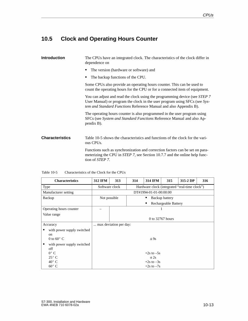
10-13S7-300, Installation and HardwareEWA 4NEB 710 6078-02a
10.5 Clock and Operating Hours Counter
The CPUs have an integrated clock. The characteristics of the clock differ independence on
The version (hardware or software) and
The backup functions of the CPU.
Some CPUs also provide an operating hours counter. This can be used tocount the operating hours for the CPU or for a connected item of equipment.
You can adjust and read the clock using the programming device (see STEP 7User Manual) or program the clock in the user program using SFCs (see Sys-tem and Standard Functions Reference Manual and also Appendix B).
The operating hours counter is also programmed in the user program usingSFCs (see System and Standard Functions Reference Manual and also Ap-pendix B).
Table 10-5 shows the characteristics and functions of the clock for the vari-ous CPUs.
Functions such as synchronization and correction factors can be set on para-meterizing the CPU in STEP 7, see Section 10.7.7 and the online help func-tion of STEP 7.
Table 10-5 Characteristics of the Clock for the CPUs
Characteristics 312 IFM 313 314 314 IFM 315 315-2 DP 316
Type Software clock Hardware clock (integrated “real-time clock”)
Manufacturer setting DT#1994-01-01-00:00:00
Backup Not possible Backup battery
Rechargeable Battery
Operating hours counter
Value range
– 1
0 to 32767 hours
Accuracy
with power supply switchedon 0 to 60 C
with power supply switchedoff0 C25 C40 C60 C
... max deviation per day:
9s
+2s to –5s2s
+2s to –3s+2s to –7s
Introduction
Characteristics
CPUs
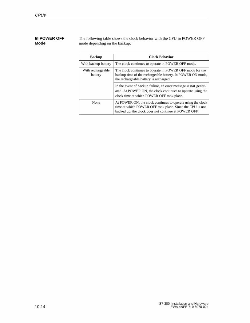
10-14S7-300, Installation and Hardware
EWA 4NEB 710 6078-02a
The following table shows the clock behavior with the CPU in POWER OFFmode depending on the backup:
Backup Clock Behavior
With backup battery The clock continues to operate in POWER OFF mode.
With rechargeablebattery
The clock continues to operate in POWER OFF mode for thebackup time of the rechargeable battery. In POWER ON mode,the rechargeable battery is recharged.
In the event of backup failure, an error message is not gener-ated. At POWER ON, the clock continues to operate using theclock time at which POWER OFF took place.
None At POWER ON, the clock continues to operate using the clocktime at which POWER OFF took place. Since the CPU is notbacked up, the clock does not continue at POWER OFF.
In POWER OFFMode
CPUs
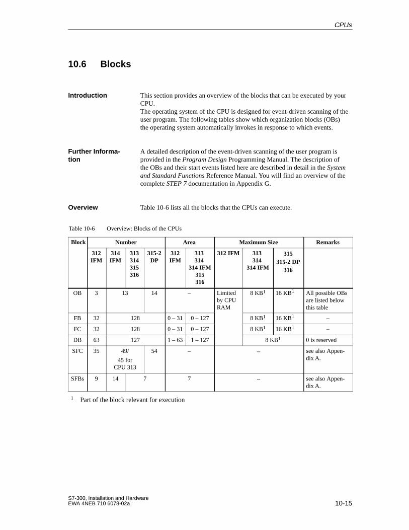
10-15S7-300, Installation and HardwareEWA 4NEB 710 6078-02a
10.6 Blocks
This section provides an overview of the blocks that can be executed by yourCPU.The operating system of the CPU is designed for event-driven scanning of theuser program. The following tables show which organization blocks (OBs)the operating system automatically invokes in response to which events.
A detailed description of the event-driven scanning of the user program isprovided in the Program Design Programming Manual. The description ofthe OBs and their start events listed here are described in detail in the Systemand Standard Functions Reference Manual. You will find an overview of thecomplete STEP 7 documentation in Appendix G.
Overview Table 10-6 lists all the blocks that the CPUs can execute.
Table 10-6 Overview: Blocks of the CPUs
Block Number Area Maximum Size Remarks
312IFM
314IFM
313314315316
315-2DP
312IFM
313 314
314 IFM315316
312 IFM 313 314
314 IFM
315315-2 DP
316
OB 3 13 14 – Limitedby CPURAM
8 KB1 16 KB1 All possible OBsare listed belowthis table
FB 32 128 0 – 31 0 – 127 8 KB1 16 KB1 –
FC 32 128 0 – 31 0 – 127 8 KB1 16 KB1 –
DB 63 127 1 – 63 1 – 127 8 KB1 0 is reserved
SFC 35 49/
45 forCPU 313
54 – – see also Appen-dix A.
SFBs 9 14 7 7 – see also Appen-dix A.
1 Part of the block relevant for execution
Introduction
Further Informa -tion
CPUs
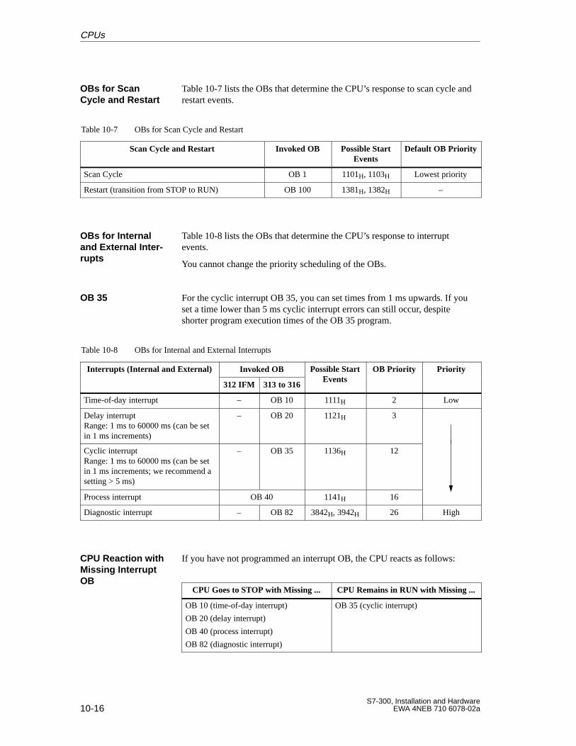
10-16S7-300, Installation and Hardware
EWA 4NEB 710 6078-02a
Table 10-7 lists the OBs that determine the CPU’s response to scan cycle andrestart events.
Table 10-7 OBs for Scan Cycle and Restart
Scan Cycle and Restart Invoked OB Possible StartEvents
Default OB Priority
Scan Cycle OB 1 1101H, 1103H Lowest priority
Restart (transition from STOP to RUN) OB 100 1381H, 1382H –
Table 10-8 lists the OBs that determine the CPU’s response to interruptevents.
You cannot change the priority scheduling of the OBs.
For the cyclic interrupt OB 35, you can set times from 1 ms upwards. If youset a time lower than 5 ms cyclic interrupt errors can still occur, despiteshorter program execution times of the OB 35 program.
Table 10-8 OBs for Internal and External Interrupts
Interrupts (Internal and External) Invoked OB Possible StartEvents
OB Priority Priorityp ( )
312 IFM 313 to 316Events
y y
Time-of-day interrupt – OB 10 1111H 2 Low
Delay interruptRange: 1 ms to 60000 ms (can be setin 1 ms increments)
– OB 20 1121H 3
Cyclic interruptRange: 1 ms to 60000 ms (can be setin 1 ms increments; we recommend asetting > 5 ms)
– OB 35 1136H 12
Process interrupt OB 40 1141H 16
Diagnostic interrupt – OB 82 3842H, 3942H 26 High
If you have not programmed an interrupt OB, the CPU reacts as follows:
CPU Goes to STOP with Missing ... CPU Remains in RUN with Missing ...
OB 10 (time-of-day interrupt)
OB 20 (delay interrupt)
OB 40 (process interrupt)
OB 82 (diagnostic interrupt)
OB 35 (cyclic interrupt)
OBs for ScanCycle and Restart
OBs for Internaland External Inter -rupts
OB 35
CPU Reaction withMissing InterruptOB
CPUs
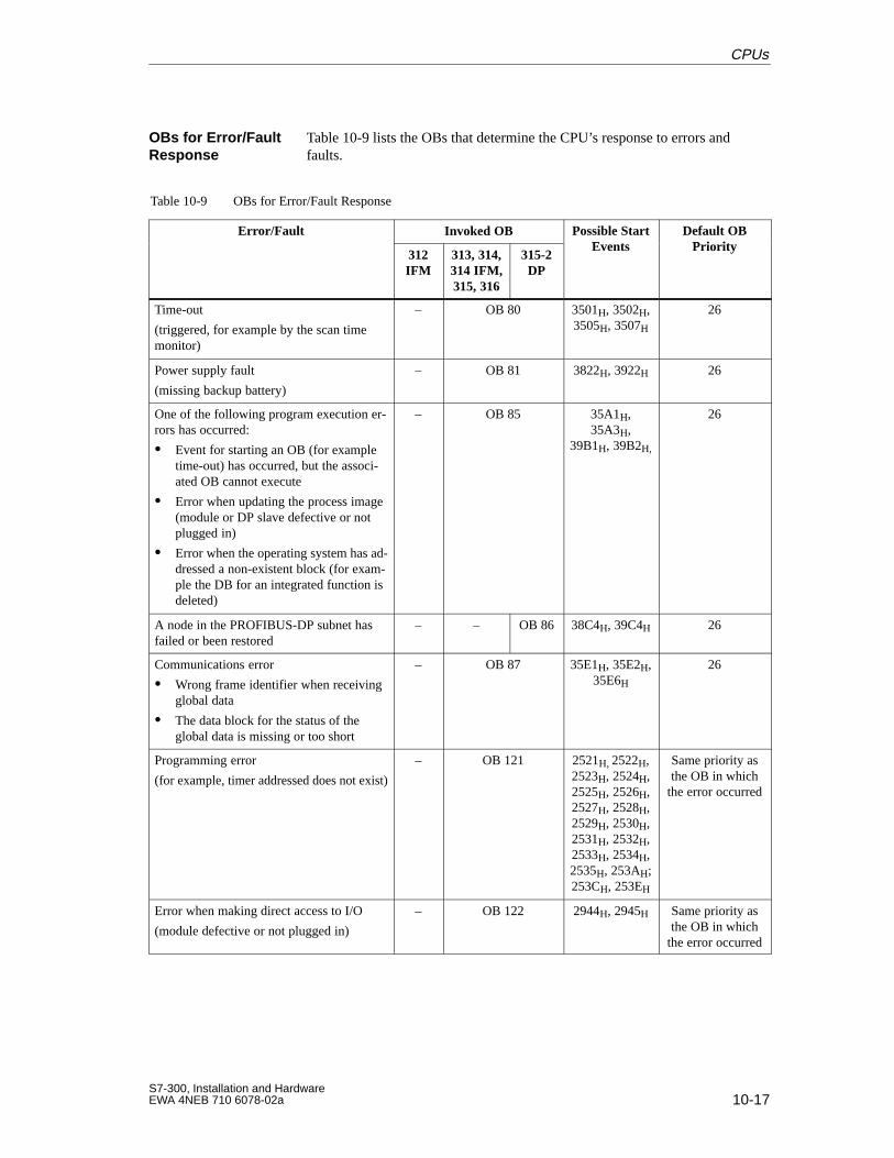
10-17S7-300, Installation and HardwareEWA 4NEB 710 6078-02a
Table 10-9 lists the OBs that determine the CPU’s response to errors andfaults.
Table 10-9 OBs for Error/Fault Response
Error/Fault Invoked OB Possible StartEvents
Default OBPriority
312IFM
313, 314,314 IFM,315, 316
315-2DP
Events Priority
Time-out
(triggered, for example by the scan timemonitor)
– OB 80 3501H, 3502H,3505H, 3507H
26
Power supply fault
(missing backup battery)
– OB 81 3822H, 3922H 26
One of the following program execution er-rors has occurred:
Event for starting an OB (for exampletime-out) has occurred, but the associ-ated OB cannot execute
Error when updating the process image(module or DP slave defective or notplugged in)
Error when the operating system has ad-dressed a non-existent block (for exam-ple the DB for an integrated function isdeleted)
– OB 85 35A1H,35A3H,
39B1H, 39B2H,
26
A node in the PROFIBUS-DP subnet hasfailed or been restored
– – OB 86 38C4H, 39C4H 26
Communications error
Wrong frame identifier when receivingglobal data
The data block for the status of theglobal data is missing or too short
– OB 87 35E1H, 35E2H,35E6H
26
Programming error
(for example, timer addressed does not exist)
– OB 121 2521H, 2522H,2523H, 2524H,2525H, 2526H,2527H, 2528H,2529H, 2530H,2531H, 2532H,2533H, 2534H,2535H, 253AH;253CH, 253EH
Same priority asthe OB in which
the error occurred
Error when making direct access to I/O
(module defective or not plugged in)
– OB 122 2944H, 2945H Same priority asthe OB in which
the error occurred
OBs for Error/FaultResponse
CPUs
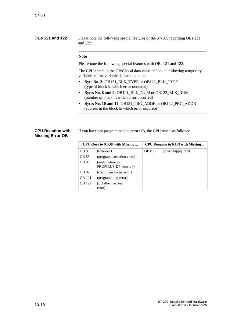
10-18S7-300, Installation and Hardware
EWA 4NEB 710 6078-02a
Please note the following special features of the S7-300 regarding OBs 121and 122:
Note
Please note the following special features with OBs 121 and 122:
The CPU enters in the OBs’ local data value “0” in the following temporaryvariables of the variable declaration table:
Byte No. 3: OB121_BLK_TYPE or OB122_BLK_TYPE (type of block in which error occurred)
Bytes No. 8 and 9: OB121_BLK_NUM or OB122_BLK_NUM (number of block in which error occurred)
Bytes No. 10 and 11: OB121_PRG_ADDR or OB122_PRG_ADDR (address in the block in which error occurred)
If you have not programmed an error OB, the CPU reacts as follows:
CPU Goes to STOP with Missing ... CPU Remains in RUN with Missing ...
OB 80 (time-out)
OB 85 (program execution error)
OB 86 (node failure in PROFIBUS-DP network)
OB 87 (communications error)
OB 121 (programming error)
OB 122 (I/O direct access error)
OB 81 (power supply fault)
OBs 121 and 122
CPU Reaction withMissing Error OB
CPUs
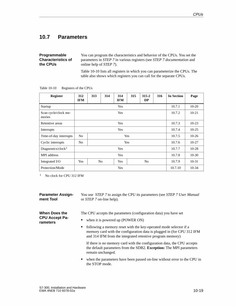
10-19S7-300, Installation and HardwareEWA 4NEB 710 6078-02a
10.7 Parameters
You can program the characteristics and behavior of the CPUs. You set theparameters in STEP 7 in various registers (see STEP 7 documentation andonline help of STEP 7).
Table 10-10 lists all registers in which you can parameterize the CPUs. Thetable also shows which registers you can call for the separate CPUs.
Table 10-10 Registers of the CPUs
Register 312IFM
313 314 314IFM
315 315-2 DP
316 In Section Page
Startup Yes 10.7.1 10-20
Scan cycle/clock me-mories
Yes 10.7.2 10-21
Retentive areas Yes 10.7.3 10-23
Interrupts Yes 10.7.4 10-25
Time-of-day interrupts No Yes 10.7.5 10-26
Cyclic interrupts No Yes 10.7.6 10-27
Diagnostics/clock1 Yes 10.7.7 10-28
MPI address Yes 10.7.8 10-30
Integrated I/O Yes No Yes No 10.7.9 10-31
Protection/Mode Yes 10.7.10 10-34
1 No clock for CPU 312 IFM
You use STEP 7 to assign the CPU its parameters (see STEP 7 User Manualor STEP 7 on-line help).
The CPU accepts the parameters (configuration data) you have set
when it is powered up (POWER ON)
following a memory reset with the key-operated mode selector if amemory card with the configuration data is plugged in (for CPU 312 IFMand 314 IFM from the integrated retentive program memory)
If there is no memory card with the configuration data, the CPU acceptsthe default parameters from the SDB2. Exception: The MPI parametersremain unchanged.
when the parameters have been passed on-line without error to the CPU inthe STOP mode.
ProgrammableCharacteristics ofthe CPUs
Parameter Assign -ment Tool
When Does theCPU Accept Pa -rameters
CPUs
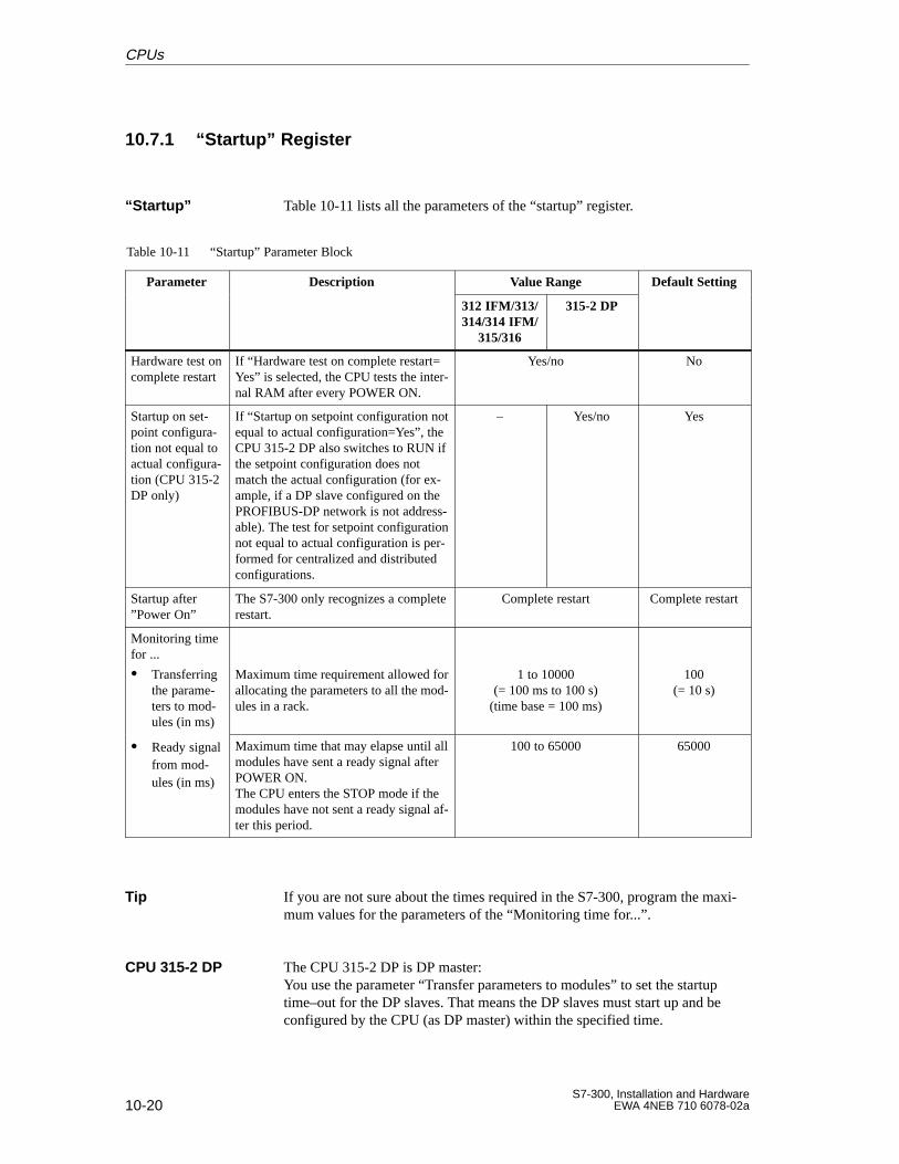
10-20S7-300, Installation and Hardware
EWA 4NEB 710 6078-02a
10.7.1 “Startup” Register
Table 10-11 lists all the parameters of the “startup” register.
Table 10-11 “Startup” Parameter Block
Parameter Description Value Range Default Settingp
312 IFM/313/314/314 IFM/
315/316
315-2 DP
g
Hardware test oncomplete restart
If “Hardware test on complete restart=Yes” is selected, the CPU tests the inter-nal RAM after every POWER ON.
Yes/no No
Startup on set-point configura-tion not equal toactual configura-tion (CPU 315-2DP only)
If “Startup on setpoint configuration notequal to actual configuration=Yes”, theCPU 315-2 DP also switches to RUN ifthe setpoint configuration does notmatch the actual configuration (for ex-ample, if a DP slave configured on thePROFIBUS-DP network is not address-able). The test for setpoint configurationnot equal to actual configuration is per-formed for centralized and distributedconfigurations.
– Yes/no Yes
Startup after”Power On”
The S7-300 only recognizes a completerestart.
Complete restart Complete restart
Monitoring timefor ...
Transferringthe parame-ters to mod-ules (in ms)
Maximum time requirement allowed forallocating the parameters to all the mod-ules in a rack.
1 to 10000(= 100 ms to 100 s)
(time base = 100 ms)
100(= 10 s)
Ready signalfrom mod-ules (in ms)
Maximum time that may elapse until allmodules have sent a ready signal afterPOWER ON.The CPU enters the STOP mode if themodules have not sent a ready signal af-ter this period.
100 to 65000 65000
If you are not sure about the times required in the S7-300, program the maxi-mum values for the parameters of the “Monitoring time for...”.
The CPU 315-2 DP is DP master:You use the parameter “Transfer parameters to modules” to set the startuptime–out for the DP slaves. That means the DP slaves must start up and beconfigured by the CPU (as DP master) within the specified time.
“Startup”
Tip
CPU 315-2 DP
CPUs
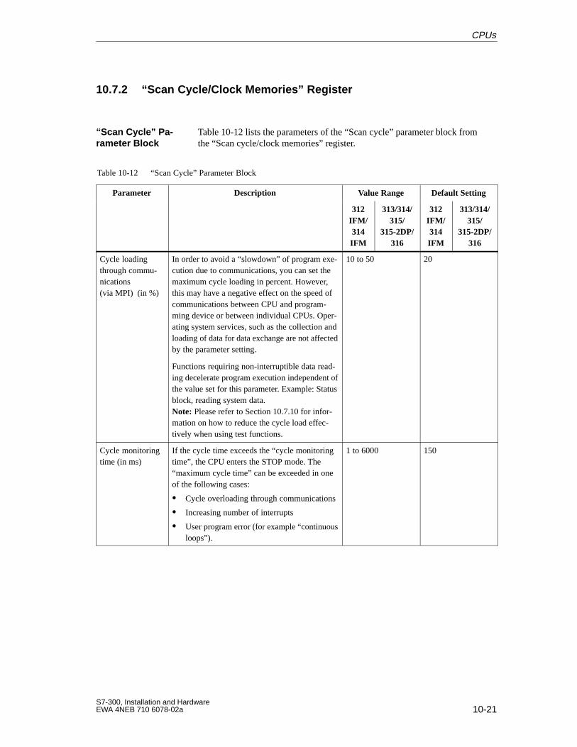
10-21S7-300, Installation and HardwareEWA 4NEB 710 6078-02a
10.7.2 “Scan Cycle/Clock Memories” Register
Table 10-12 lists the parameters of the “Scan cycle” parameter block fromthe “Scan cycle/clock memories” register.
Table 10-12 “Scan Cycle” Parameter Block
Parameter Description Value Range Default Settingp
312IFM/314IFM
313/314/315/
315-2DP/316
312IFM/314IFM
313/314/315/
315-2DP/316
Cycle loadingthrough commu-nications(via MPI) (in %)
In order to avoid a “slowdown” of program exe-cution due to communications, you can set themaximum cycle loading in percent. However,this may have a negative effect on the speed ofcommunications between CPU and program-ming device or between individual CPUs. Oper-ating system services, such as the collection andloading of data for data exchange are not affectedby the parameter setting.
Functions requiring non-interruptible data read-ing decelerate program execution independent ofthe value set for this parameter. Example: Statusblock, reading system data.Note: Please refer to Section 10.7.10 for infor-mation on how to reduce the cycle load effec-tively when using test functions.
10 to 50 20
Cycle monitoringtime (in ms)
If the cycle time exceeds the “cycle monitoringtime”, the CPU enters the STOP mode. The“maximum cycle time” can be exceeded in oneof the following cases:
Cycle overloading through communications
Increasing number of interrupts
User program error (for example “continuousloops”).
1 to 6000 150
“Scan Cycle” Pa -rameter Block
CPUs
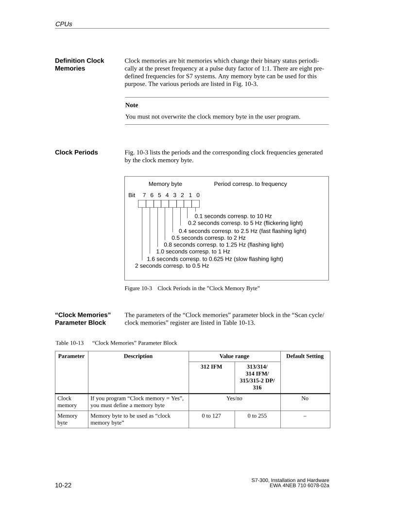
10-22S7-300, Installation and Hardware
EWA 4NEB 710 6078-02a
Clock memories are bit memories which change their binary status periodi-cally at the preset frequency at a pulse duty factor of 1:1. There are eight pre-defined frequencies for S7 systems. Any memory byte can be used for thispurpose. The various periods are listed in Fig. 10-3.
Note
You must not overwrite the clock memory byte in the user program.
Fig. 10-3 lists the periods and the corresponding clock frequencies generatedby the clock memory byte.
234567 01Bit
Memory byte
0.1 seconds corresp. to 10 Hz0.2 seconds corresp. to 5 Hz (flickering light)
0.4 seconds corresp. to 2.5 Hz (fast flashing light)0.5 seconds corresp. to 2 Hz
0.8 seconds corresp. to 1.25 Hz (flashing light)1.0 seconds corresp. to 1 Hz
1.6 seconds corresp. to 0.625 Hz (slow flashing light)2 seconds corresp. to 0.5 Hz
Period corresp. to frequency
Figure 10-3 Clock Periods in the ”Clock Memory Byte”
The parameters of the “Clock memories” parameter block in the “Scan cycle/clock memories” register are listed in Table 10-13.
Table 10-13 “Clock Memories” Parameter Block
Parameter Description Value range Default Settingp
312 IFM 313/314/314 IFM/
315/315-2 DP/316
g
Clockmemory
If you program “Clock memory = Yes”,you must define a memory byte
Yes/no No
Memorybyte
Memory byte to be used as “clockmemory byte”
0 to 127 0 to 255 –
Definition ClockMemories
Clock Periods
“Clock Memories”Parameter Block
CPUs
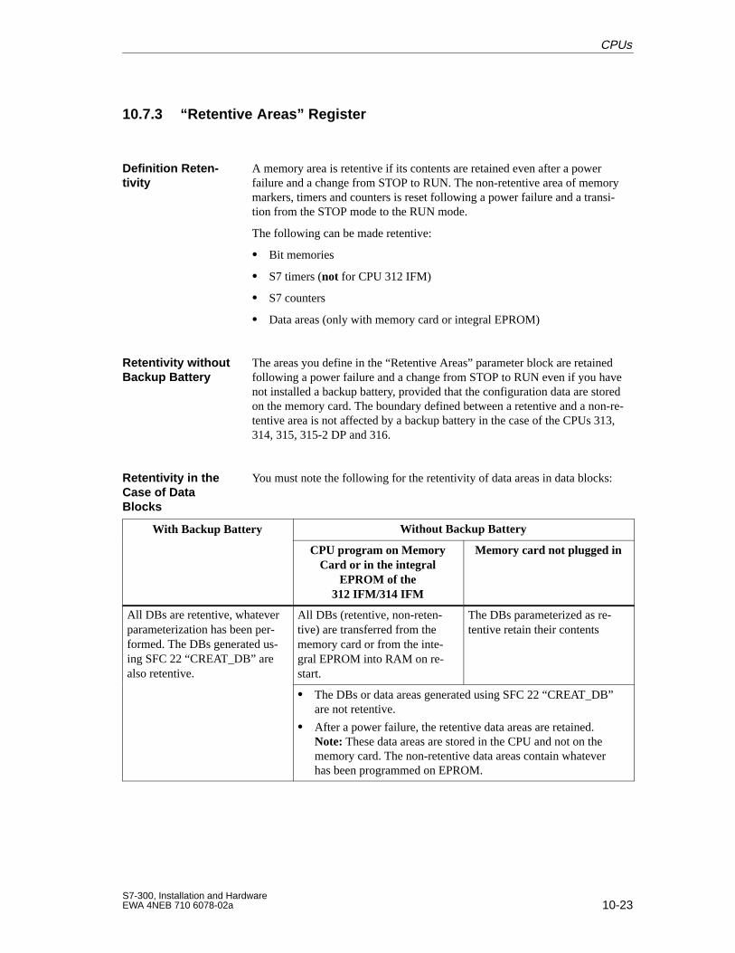
10-23S7-300, Installation and HardwareEWA 4NEB 710 6078-02a
10.7.3 “Retentive Areas” Register
A memory area is retentive if its contents are retained even after a powerfailure and a change from STOP to RUN. The non-retentive area of memorymarkers, timers and counters is reset following a power failure and a transi-tion from the STOP mode to the RUN mode.
The following can be made retentive:
Bit memories
S7 timers (not for CPU 312 IFM)
S7 counters
Data areas (only with memory card or integral EPROM)
The areas you define in the “Retentive Areas” parameter block are retainedfollowing a power failure and a change from STOP to RUN even if you havenot installed a backup battery, provided that the configuration data are storedon the memory card. The boundary defined between a retentive and a non-re-tentive area is not affected by a backup battery in the case of the CPUs 313,314, 315, 315-2 DP and 316.
You must note the following for the retentivity of data areas in data blocks:
With Backup Battery Without Backup Batteryp y
CPU program on MemoryCard or in the integral
EPROM of the312 IFM/314 IFM
Memory card not plugged in
All DBs are retentive, whateverparameterization has been per-formed. The DBs generated us-ing SFC 22 “CREAT_DB” arealso retentive.
All DBs (retentive, non-reten-tive) are transferred from thememory card or from the inte-gral EPROM into RAM on re-start.
The DBs parameterized as re-tentive retain their contents
The DBs or data areas generated using SFC 22 “CREAT_DB”are not retentive.
After a power failure, the retentive data areas are retained.Note: These data areas are stored in the CPU and not on thememory card. The non-retentive data areas contain whateverhas been programmed on EPROM.
Definition Reten-tivity
Retentivity withoutBackup Battery
Retentivity in theCase of DataBlocks
CPUs
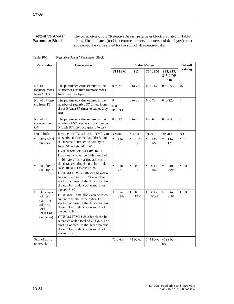
10-24S7-300, Installation and Hardware
EWA 4NEB 710 6078-02a
The parameters of the “Retentive Areas” parameter block are listed in Table10-14. The total area (for bit memories, timers, counters and data bytes) mustnot exceed the value stated for the sum of all retentive data.
Table 10-14 “Retentive Areas” Parameter Block
Parameter Description Value Range DefaultSetting
p
312 IFM 313 314 IFM 314, 315,315-2 DP,
316
Setting
No. ofmemory bytesfrom MB 0
The parameter value entered is thenumber of retentive memory bytesfrom memory byte 0
0 to 72 0 to 72 0 to 144 0 to 256 16
No. of S7 tim-ers from T0
The parameter value entered is thenumber of retentive S7 timers fromtimer 0 (each S7 timer occupies 2 by-tes)
0
(non-re-tentive)
0 to 36 0 to 72 0 to 128 0
No. of S7counters fromC0
The parameter value entered is thenumber of S7 counters from counter0 (each S7 timer occupies 2 bytes)
0 to 32 0 to 36 0 to 64 0 to 64 8
Data block
Data blocknumber
If you enter “Data block = Yes”, youmust also define the data block andthe desired “number of data bytes”from “data byte address”.
CPU 314/315/315-2 DP/316: 8DBs can be retentive with a total of4096 bytes. The starting address ofth d t l th b f d t
Yes/no
1 to 63
Yes/no
1 to 127
Yes/no
1 to 127
Yes/no
1 to 127
No
1
Number ofdata bytes
y gthe data area plus the number of databytes must not exceed 8192.
CPU 314 IFM: 2 DBs can be reten-tive with a total of 144 bytes. Thestarting address of the data area plusthe number of data bytes must notexceed 8192
0 to72
0 to 72
0 to 144
0 to 4096
0
Data byteaddress(startingaddresswithlength ofdata area)
exceed 8192.
CPU 313: 1 data block can be reten-tive with a total of 72 bytes. Thestarting address of the data area plusthe number of data bytes must notexceed 8192.
CPU 312 IFM: 1 data block can beretentive with a total of 72 bytes. Thestarting address of the data area plusthe number of data bytes must notexceed 6143.
0 to 6143
0 to 8191
0 to 8191
0 to 8191
0
Sum of all re-tentive data
72 bytes 72 bytes 144 bytes 4736 by-tes
“Retentive Areas”Parameter Block
CPUs
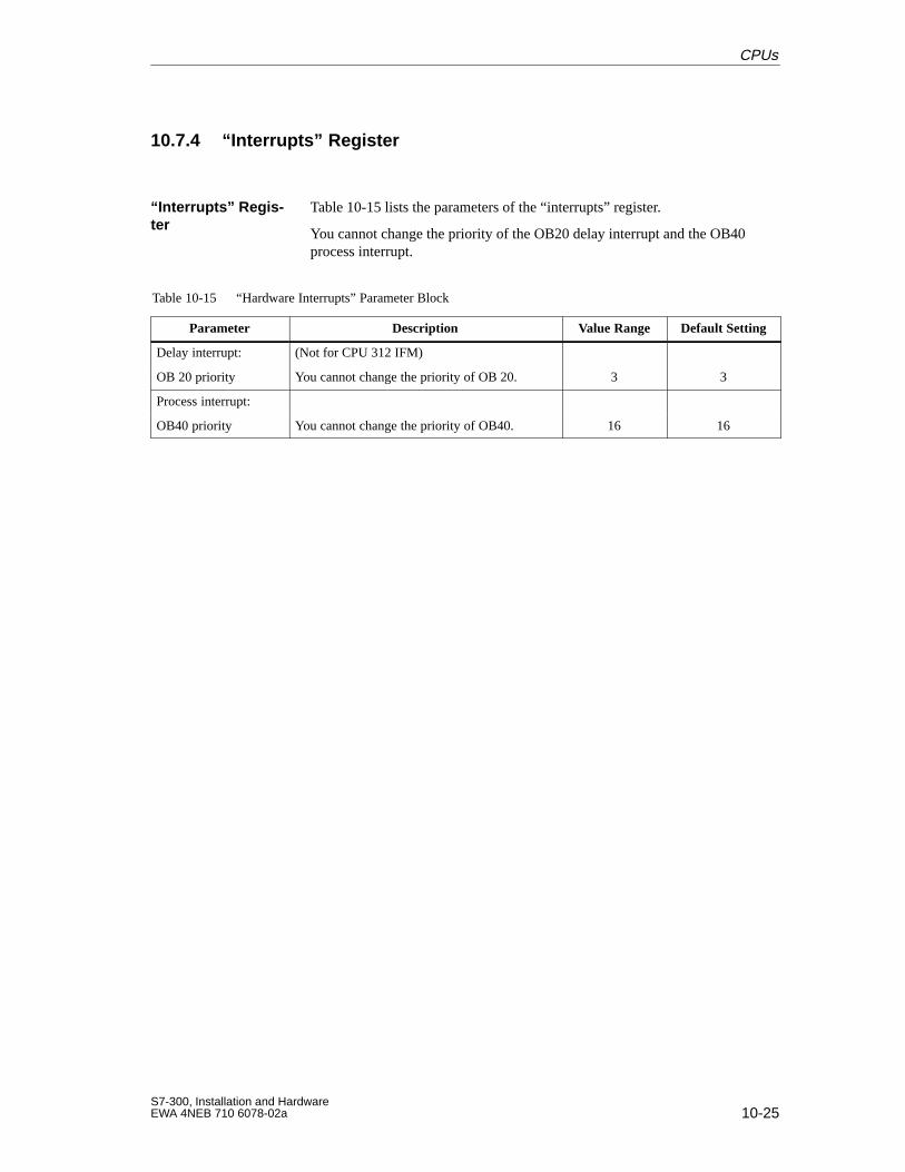
10-25S7-300, Installation and HardwareEWA 4NEB 710 6078-02a
10.7.4 “Interrupts” Register
Table 10-15 lists the parameters of the “interrupts” register.
You cannot change the priority of the OB20 delay interrupt and the OB40process interrupt.
Table 10-15 “Hardware Interrupts” Parameter Block
Parameter Description Value Range Default Setting
Delay interrupt: (Not for CPU 312 IFM)
OB 20 priority You cannot change the priority of OB 20. 3 3
Process interrupt:
OB40 priority You cannot change the priority of OB40. 16 16
“Interrupts” Regis -ter
CPUs
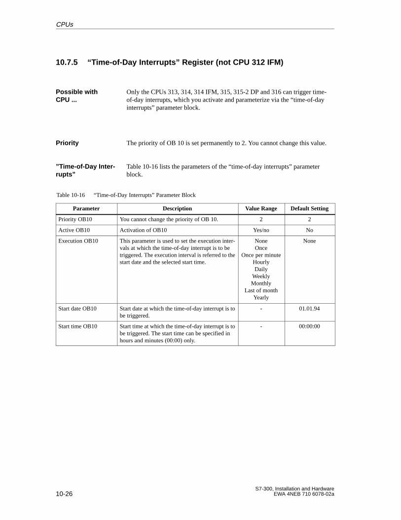
10-26S7-300, Installation and Hardware
EWA 4NEB 710 6078-02a
10.7.5 “Time-of-Day Interrupts” Register (not CPU 312 IFM)
Only the CPUs 313, 314, 314 IFM, 315, 315-2 DP and 316 can trigger time-of-day interrupts, which you activate and parameterize via the “time-of-dayinterrupts” parameter block.
The priority of OB 10 is set permanently to 2. You cannot change this value.
Table 10-16 lists the parameters of the “time-of-day interrupts” parameterblock.
Table 10-16 “Time-of-Day Interrupts” Parameter Block
Parameter Description Value Range Default Setting
Priority OB10 You cannot change the priority of OB 10. 2 2
Active OB10 Activation of OB10 Yes/no No
Execution OB10 This parameter is used to set the execution inter-vals at which the time-of-day interrupt is to betriggered. The execution interval is referred to thestart date and the selected start time.
NoneOnce
Once per minuteHourlyDaily
WeeklyMonthly
Last of monthYearly
None
Start date OB10 Start date at which the time-of-day interrupt is tobe triggered.
- 01.01.94
Start time OB10 Start time at which the time-of-day interrupt is tobe triggered. The start time can be specified inhours and minutes (00:00) only.
- 00:00:00
Possible with CPU ...
Priority
”T ime-of-Day Inter -rupts”
CPUs
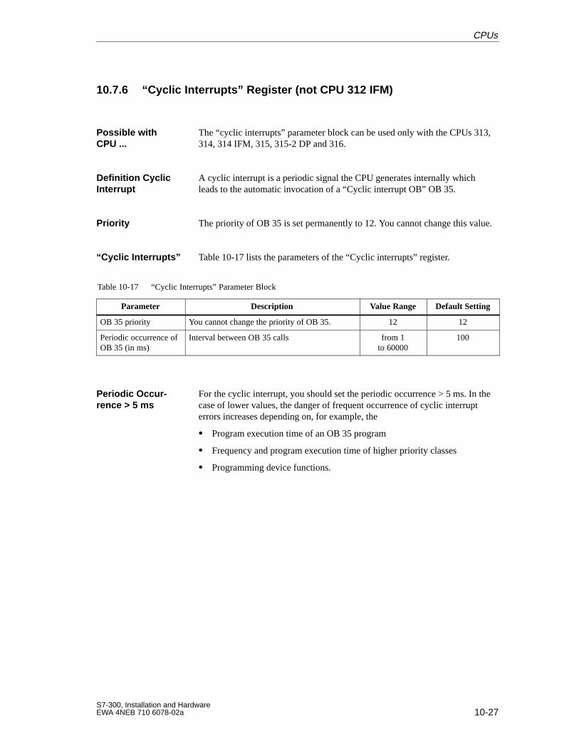
10-27S7-300, Installation and HardwareEWA 4NEB 710 6078-02a
10.7.6 “Cyclic Interrupts” Register (not CPU 312 IFM)
The “cyclic interrupts” parameter block can be used only with the CPUs 313,314, 314 IFM, 315, 315-2 DP and 316.
A cyclic interrupt is a periodic signal the CPU generates internally whichleads to the automatic invocation of a “Cyclic interrupt OB” OB 35.
The priority of OB 35 is set permanently to 12. You cannot change this value.
Table 10-17 lists the parameters of the “Cyclic interrupts” register.
Table 10-17 “Cyclic Interrupts” Parameter Block
Parameter Description Value Range Default Setting
OB 35 priority You cannot change the priority of OB 35. 12 12
Periodic occurrence ofOB 35 (in ms)
Interval between OB 35 calls from 1to 60000
100
For the cyclic interrupt, you should set the periodic occurrence > 5 ms. In thecase of lower values, the danger of frequent occurrence of cyclic interrupterrors increases depending on, for example, the
Program execution time of an OB 35 program
Frequency and program execution time of higher priority classes
Programming device functions.
Possible with CPU ...
Definition CyclicInterrupt
Priority
“Cyclic Interrupts”
Periodic Occur -rence > 5 ms
CPUs
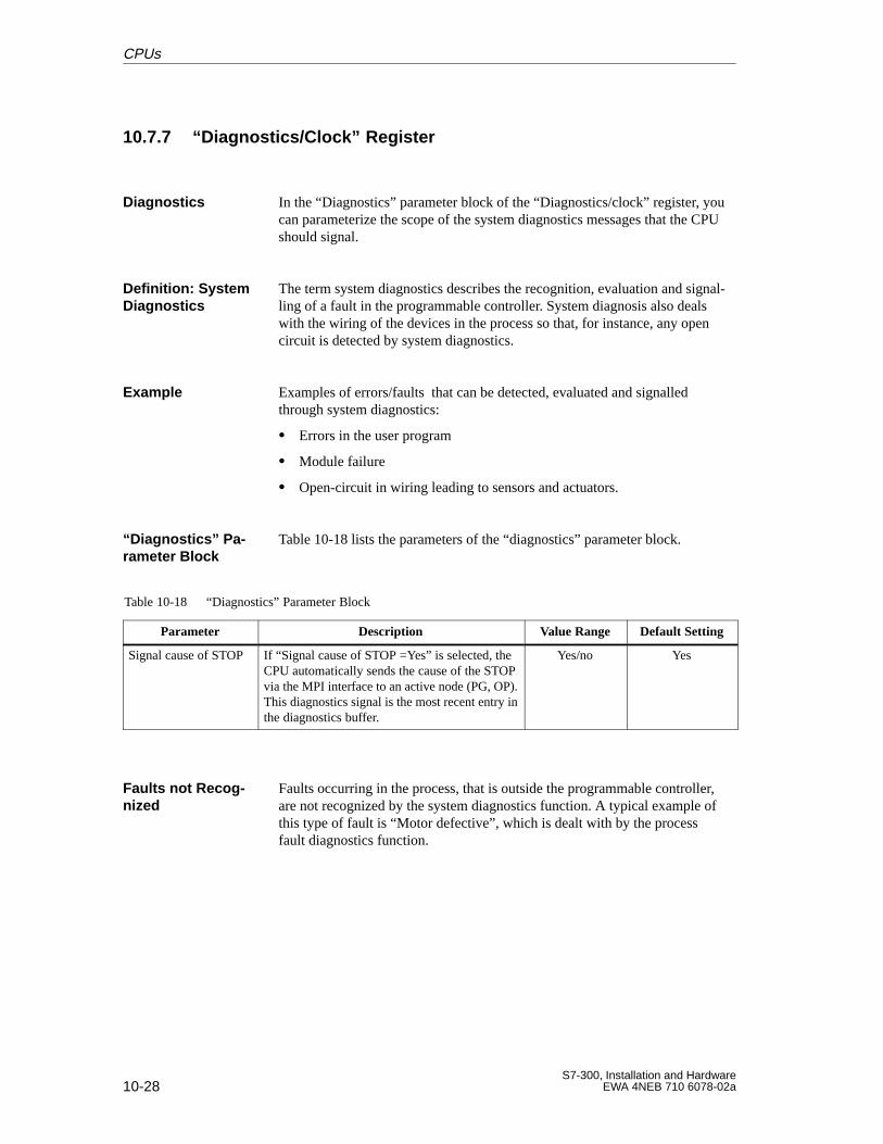
10-28S7-300, Installation and Hardware
EWA 4NEB 710 6078-02a
10.7.7 “Diagnostics/Clock” Register
In the “Diagnostics” parameter block of the “Diagnostics/clock” register, youcan parameterize the scope of the system diagnostics messages that the CPUshould signal.
The term system diagnostics describes the recognition, evaluation and signal-ling of a fault in the programmable controller. System diagnosis also dealswith the wiring of the devices in the process so that, for instance, any opencircuit is detected by system diagnostics.
Examples of errors/faults that can be detected, evaluated and signalledthrough system diagnostics:
Errors in the user program
Module failure
Open-circuit in wiring leading to sensors and actuators.
Table 10-18 lists the parameters of the “diagnostics” parameter block.
Table 10-18 “Diagnostics” Parameter Block
Parameter Description Value Range Default Setting
Signal cause of STOP If “Signal cause of STOP =Yes” is selected, theCPU automatically sends the cause of the STOPvia the MPI interface to an active node (PG, OP).This diagnostics signal is the most recent entry inthe diagnostics buffer.
Yes/no Yes
Faults occurring in the process, that is outside the programmable controller,are not recognized by the system diagnostics function. A typical example ofthis type of fault is “Motor defective”, which is dealt with by the processfault diagnostics function.
Diagnostics
Definition: SystemDiagnostics
Example
“Diagnostics” Pa -rameter Block
Faults not Recog-nized
CPUs
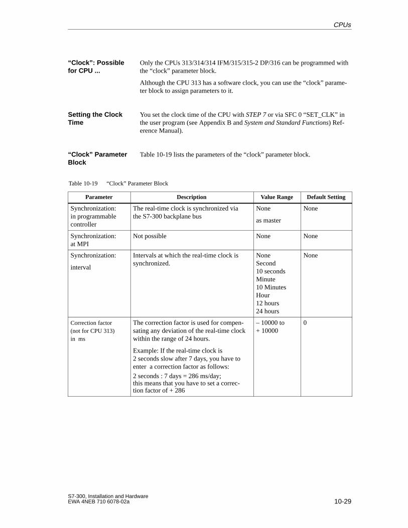
10-29S7-300, Installation and HardwareEWA 4NEB 710 6078-02a
Only the CPUs 313/314/314 IFM/315/315-2 DP/316 can be programmed withthe “clock” parameter block.
Although the CPU 313 has a software clock, you can use the “clock” parame-ter block to assign parameters to it.
You set the clock time of the CPU with STEP 7 or via SFC 0 “SET_CLK” inthe user program (see Appendix B and System and Standard Functions) Ref-erence Manual).
Table 10-19 lists the parameters of the “clock” parameter block.
Table 10-19 “Clock” Parameter Block
Parameter Description Value Range Default Setting
Synchronization:in programmablecontroller
The real-time clock is synchronized viathe S7-300 backplane bus
None
as master
None
Synchronization:at MPI
Not possible None None
Synchronization:
interval
Intervals at which the real-time clock issynchronized.
NoneSecond10 secondsMinute10 MinutesHour12 hours24 hours
None
Correction factor(not for CPU 313)in ms
The correction factor is used for compen-sating any deviation of the real-time clockwithin the range of 24 hours.
Example: If the real-time clock is 2 seconds slow after 7 days, you have toenter a correction factor as follows:
2 seconds : 7 days = 286 ms/day;this means that you have to set a correc-tion factor of + 286
– 10000 to+ 10000
0
“Clock”: Possiblefor CPU ...
Setting the ClockTime
“Clock” ParameterBlock
CPUs
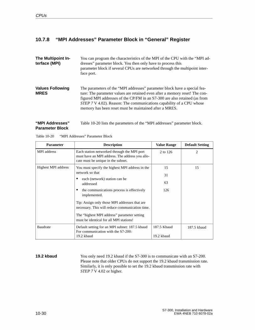
10-30S7-300, Installation and Hardware
EWA 4NEB 710 6078-02a
10.7.8 “MPI Addresses” Parameter Block in “General” Register
You can program the characteristics of the MPI of the CPU with the “MPI ad-dresses” parameter block. You then only have to process this parameter block if several CPUs are networked through the multipoint inter-face port.
The parameters of the “MPI addresses” parameter block have a special fea-ture: The parameter values are retained even after a memory reset! The con-figured MPI addresses of the CP/FM in an S7-300 are also retained (as fromSTEP 7 V 4.02). Reason: The communications capability of a CPU whosememory has been reset must be maintained after a MRES.
Table 10-20 lists the parameters of the “MPI addresses” parameter block.
Table 10-20 “MPI Addresses” Parameter Block
Parameter Description Value Range Default Setting
MPI address Each station networked through the MPI portmust have an MPI address. The address you allo-cate must be unique in the subnet.
2 to 126 2
Highest MPI address You must specify the highest MPI address in thenetwork so that
each (network) station can be addressed
the communications process is effectivelyimplemented.
Tip: Assign only those MPI addresses that arenecessary. This will reduce communication time.
The “highest MPI address” parameter settingmust be identical for all MPI stations!
15
31
63
126
15
Baudrate Default setting for an MPI subnet: 187.5 kbaudFor communication with the S7-200: 19.2 kbaud
187.5 Kbaud 19.2 kbaud
187.5 kbaud
You only need 19.2 kbaud if the S7-300 is to communicate with an S7-200.Please note that older CPUs do not support the 19.2 kbaud transmission rate.Similarly, it is only possible to set the 19.2 kbaud transmission rate withSTEP 7 V 4.02 or higher.
The Multipoint In-terface (MPI)
Values FollowingMRES
“MPI Addresses”Parameter Block
19.2 kbaud
CPUs
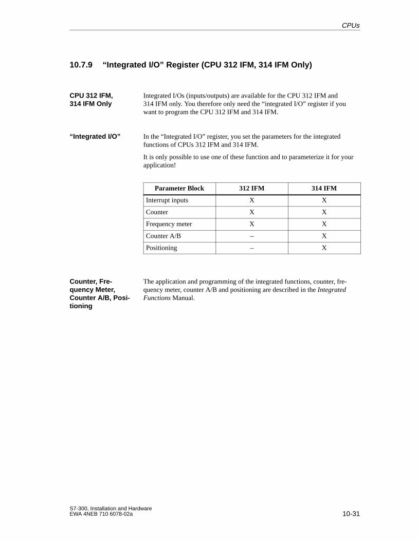
10-31S7-300, Installation and HardwareEWA 4NEB 710 6078-02a
10.7.9 “Integrated I/O” Register (CPU 312 IFM, 314 IFM Only)
Integrated I/Os (inputs/outputs) are available for the CPU 312 IFM and314 IFM only. You therefore only need the “integrated I/O” register if youwant to program the CPU 312 IFM and 314 IFM.
In the “Integrated I/O” register, you set the parameters for the integratedfunctions of CPUs 312 IFM and 314 IFM.
It is only possible to use one of these function and to parameterize it for yourapplication!
Parameter Block 312 IFM 314 IFM
Interrupt inputs X X
Counter X X
Frequency meter X X
Counter A/B – X
Positioning – X
The application and programming of the integrated functions, counter, fre-quency meter, counter A/B and positioning are described in the IntegratedFunctions Manual.
CPU 312 IFM,314 IFM Only
“Integrated I/O”
Counter , Fre-quency Meter,Counter A/B, Posi -tioning
CPUs
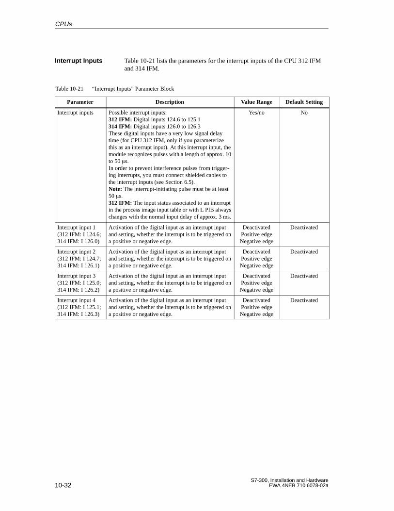
10-32S7-300, Installation and Hardware
EWA 4NEB 710 6078-02a
Table 10-21 lists the parameters for the interrupt inputs of the CPU 312 IFMand 314 IFM.
Table 10-21 “Interrupt Inputs” Parameter Block
Parameter Description Value Range Default Setting
Interrupt inputs Possible interrupt inputs:312 IFM: Digital inputs 124.6 to 125.1314 IFM: Digital inputs 126.0 to 126.3These digital inputs have a very low signal delaytime (for CPU 312 IFM, only if you parameterizethis as an interrupt input). At this interrupt input, themodule recognizes pulses with a length of approx. 10to 50 s.In order to prevent interference pulses from trigger-ing interrupts, you must connect shielded cables tothe interrupt inputs (see Section 6.5).Note: The interrupt-initiating pulse must be at least50 s.312 IFM: The input status associated to an interruptin the process image input table or with L PIB alwayschanges with the normal input delay of approx. 3 ms.
Yes/no No
Interrupt input 1(312 IFM: I 124.6;314 IFM: I 126.0)
Activation of the digital input as an interrupt inputand setting, whether the interrupt is to be triggered ona positive or negative edge.
DeactivatedPositive edgeNegative edge
Deactivated
Interrupt input 2(312 IFM: I 124.7;314 IFM: I 126.1)
Activation of the digital input as an interrupt inputand setting, whether the interrupt is to be triggered ona positive or negative edge.
DeactivatedPositive edgeNegative edge
Deactivated
Interrupt input 3(312 IFM: I 125.0;314 IFM: I 126.2)
Activation of the digital input as an interrupt inputand setting, whether the interrupt is to be triggered ona positive or negative edge.
DeactivatedPositive edgeNegative edge
Deactivated
Interrupt input 4(312 IFM: I 125.1;314 IFM: I 126.3)
Activation of the digital input as an interrupt inputand setting, whether the interrupt is to be triggered ona positive or negative edge.
DeactivatedPositive edgeNegative edge
Deactivated
Interrupt Inputs
CPUs
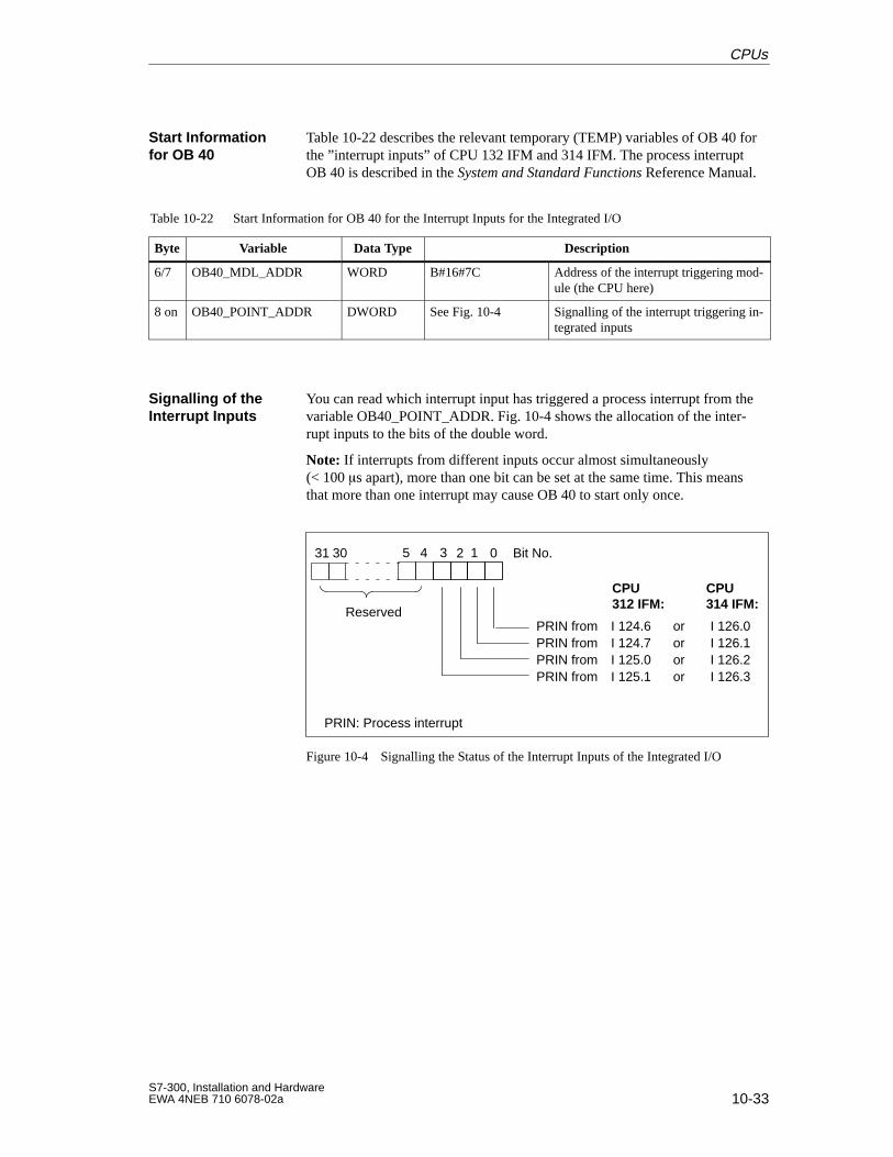
10-33S7-300, Installation and HardwareEWA 4NEB 710 6078-02a
Table 10-22 describes the relevant temporary (TEMP) variables of OB 40 forthe ”interrupt inputs” of CPU 132 IFM and 314 IFM. The process interruptOB 40 is described in the System and Standard Functions Reference Manual.
Table 10-22 Start Information for OB 40 for the Interrupt Inputs for the Integrated I/O
Byte Variable Data Type Description
6/7 OB40_MDL_ADDR WORD B#16#7C Address of the interrupt triggering mod-ule (the CPU here)
8 on OB40_POINT_ADDR DWORD See Fig. 10-4 Signalling of the interrupt triggering in-tegrated inputs
You can read which interrupt input has triggered a process interrupt from thevariable OB40_POINT_ADDR. Fig. 10-4 shows the allocation of the inter-rupt inputs to the bits of the double word.
Note: If interrupts from different inputs occur almost simultaneously(< 100 s apart), more than one bit can be set at the same time. This meansthat more than one interrupt may cause OB 40 to start only once.
0 Bit No.
PRIN from I 124.6 or I 126.0
5 4 13 231 30
PRIN from I 124.7 or I 126.1PRIN from I 125.0 or I 126.2PRIN from I 125.1 or I 126.3
Reserved
PRIN: Process interrupt
CPU312 IFM:
CPU314 IFM:
Figure 10-4 Signalling the Status of the Interrupt Inputs of the Integrated I/O
Start Informationfor OB 40
Signalling of theInterrupt Inputs
CPUs
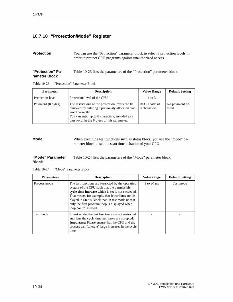
10-34S7-300, Installation and Hardware
EWA 4NEB 710 6078-02a
10.7.10 “Protection/Mode” Register
You can use the ”Protection” parameter block to select 3 protection levels inorder to protect CPU programs against unauthorized access.
Table 10-23 lists the parameters of the ”Protection” parameter block.
Table 10-23 ”Protection” Parameter Block
Parameter Description Value Range Default Setting
Protection level Protection level of the CPU 1 to 3 1
Password (8 bytes) The restrictions of the protection levels can beremoved by entering a previously allocated pass-word correctly.You can enter up to 8 characters, encoded as apassword, in the 8 bytes of this parameter.
ASCII code of8 characters
No password en-tered
When executing test functions such as status block, you use the “mode” pa-rameter block to set the scan time behavior of your CPU.
Table 10-24 lists the parameters of the ”Mode” parameter block.
Table 10-24 ”Mode” Parameter Block
Parameters Description Value range Default Setting
Process mode The test functions are restricted by the operatingsystem of the CPU such that the permissiblecycle time increase which is set is not exceeded.That means, for example, that fewer lines are dis-played in Status Block than in test mode or thatonly the first program loop is displayed whenloop control is used.
3 to 20 ms Test mode
Test mode In test mode, the test functions are not restrictedand thus the cycle time increases are accepted.Important: Please ensure that the CPU and theprocess can “tolerate” large increases in the cycletime.
- -
Protection
”Protection” Pa-rameter Block
Mode
”Mode” ParameterBlock
CPUs
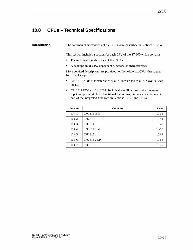
10-35S7-300, Installation and HardwareEWA 4NEB 710 6078-02a
10.8 CPUs – Technical Specifications
The common characteristics of the CPUs were described in Sections 10.2 to10.7.
This section includes a section for each CPU of the S7-300 which contains
The technical specifications of the CPU and
A description of CPU-dependent functions or characteristics.
More detailed descriptions are provided for the following CPUs due to theirfunctional scope:
CPU 315-2 DP: Characteristics as a DP master and as a DP slave in Chap-ter 11,
CPU 312 IFM and 314 IFM: Technical specifications of the integratedinputs/outputs and characteristics of the interrupt inputs as a componentpart of the integrated functions in Sections 10.8.1 and 10.8.4.
Section Contents Page
10.8.1 CPU 312 IFM 10-36
10.8.2 CPU 313 10-44
10.8.3 CPU 314 10-47
10.8.4 CPU 314 IFM 10-50
10.8.5 CPU 315 10-63
10.8.6 CPU 315-2 DP 10-66
10.8.7 CPU 316 10-70
Introduction
CPUs
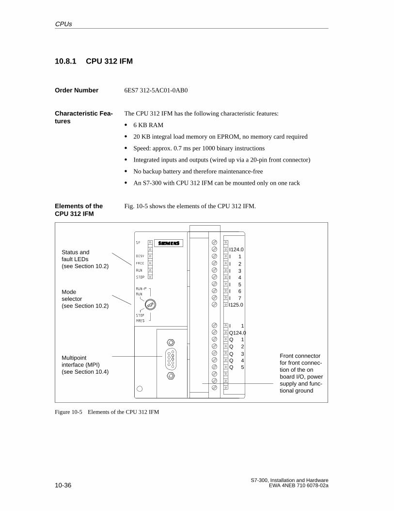
10-36S7-300, Installation and Hardware
EWA 4NEB 710 6078-02a
10.8.1 CPU 312 IFM
6ES7 312-5AC01-0AB0
The CPU 312 IFM has the following characteristic features:
6 KB RAM
20 KB integral load memory on EPROM, no memory card required
Speed: approx. 0.7 ms per 1000 binary instructions
Integrated inputs and outputs (wired up via a 20-pin front connector)
No backup battery and therefore maintenance-free
An S7-300 with CPU 312 IFM can be mounted only on one rack
Fig. 10-5 shows the elements of the CPU 312 IFM.
Status and fault LEDs(see Section 10.2)
Modeselector(see Section 10.2)
Multipoint interface (MPI)(see Section 10.4)
Front connectorfor front connec-tion of the onboard I/O, powersupply and func-tional ground
I124.0I 1I 2I 3I 4I 5I 6I 7I125.0
I 1Q124.0Q 1
Q 3Q 2
Q 4Q 5
Figure 10-5 Elements of the CPU 312 IFM
Order Number
Characteristic Fea -tures
Elements of theCPU 312 IFM
CPUs
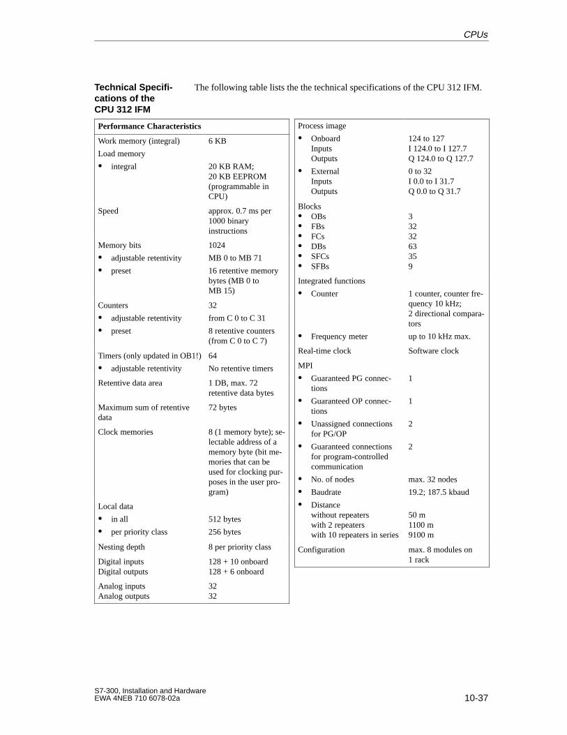
10-37S7-300, Installation and HardwareEWA 4NEB 710 6078-02a
The following table lists the the technical specifications of the CPU 312 IFM.
Performance Characteristics
Work memory (integral)
Load memory
integral
6 KB
20 KB RAM; 20 KB EEPROM(programmable inCPU)
Speed approx. 0.7 ms per1000 binaryinstructions
Memory bits
adjustable retentivity
preset
1024
MB 0 to MB 71
16 retentive memorybytes (MB 0 toMB 15)
Counters
adjustable retentivity
preset
32
from C 0 to C 31
8 retentive counters(from C 0 to C 7)
Timers (only updated in OB1!)
adjustable retentivity
64
No retentive timers
Retentive data area 1 DB, max. 72retentive data bytes
Maximum sum of retentivedata
72 bytes
Clock memories 8 (1 memory byte); se-lectable address of amemory byte (bit me-mories that can beused for clocking pur-poses in the user pro-gram)
Local data
in all
per priority class
512 bytes
256 bytes
Nesting depth 8 per priority class
Digital inputsDigital outputs
128 + 10 onboard128 + 6 onboard
Analog inputsAnalog outputs
3232
Process image
OnboardInputs Outputs
ExternalInputs Outputs
124 to 127I 124.0 to I 127.7Q 124.0 to Q 127.7
0 to 32I 0.0 to I 31.7Q 0.0 to Q 31.7
Blocks OBs FBs FCs DBs SFCs SFBs
3323263359
Integrated functions
Counter
Frequency meter
1 counter, counter fre-quency 10 kHz; 2 directional compara-tors
up to 10 kHz max.
Real-time clock Software clock
MPI
Guaranteed PG connec-tions
Guaranteed OP connec-tions
Unassigned connectionsfor PG/OP
Guaranteed connectionsfor program-controlledcommunication
No. of nodes
Baudrate
Distancewithout repeaterswith 2 repeaterswith 10 repeaters in series
1
1
2
2
max. 32 nodes
19.2; 187.5 kbaud
50 m1100 m9100 m
Configuration max. 8 modules on1 rack
Technical Specifi -cations of theCPU 312 IFM
CPUs
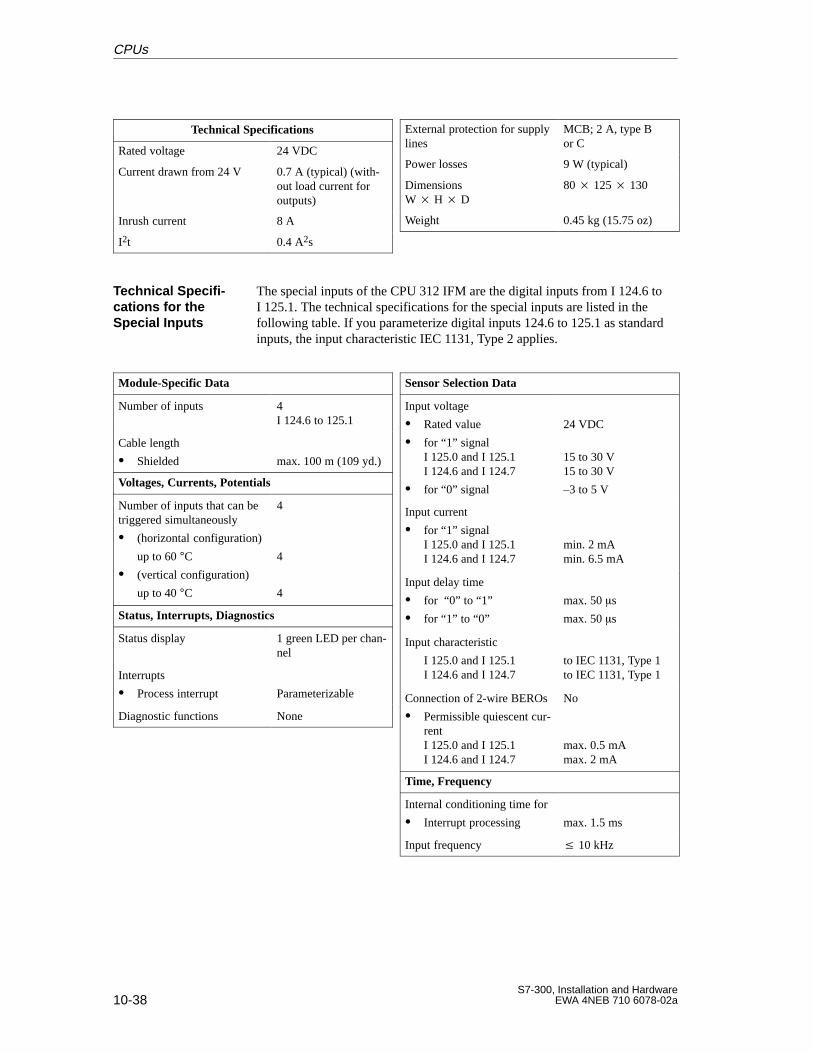
10-38S7-300, Installation and Hardware
EWA 4NEB 710 6078-02a
Technical Specifications
Rated voltage 24 VDC
Current drawn from 24 V 0.7 A (typical) (with-out load current foroutputs)
Inrush current 8 A
I2t 0.4 A2s
External protection for supplylines
MCB; 2 A, type Bor C
Power losses 9 W (typical)
DimensionsW H D
80 125 130
Weight 0.45 kg (15.75 oz)
The special inputs of the CPU 312 IFM are the digital inputs from I 124.6 toI 125.1. The technical specifications for the special inputs are listed in thefollowing table. If you parameterize digital inputs 124.6 to 125.1 as standardinputs, the input characteristic IEC 1131, Type 2 applies.
Module-Specific Data
Number of inputs 4I 124.6 to 125.1
Cable length
Shielded max. 100 m (109 yd.)
Voltages, Currents, Potentials
Number of inputs that can betriggered simultaneously
(horizontal configuration)
up to 60 °C (vertical configuration)
up to 40 °C
4
4
4
Status, Interrupts, Diagnostics
Status display 1 green LED per chan-nel
Interrupts
Process interrupt Parameterizable
Diagnostic functions None
Sensor Selection Data
Input voltage
Rated value
for “1” signalI 125.0 and I 125.1I 124.6 and I 124.7
for “0” signal
24 VDC
15 to 30 V15 to 30 V
–3 to 5 V
Input current
for “1” signalI 125.0 and I 125.1I 124.6 and I 124.7
min. 2 mAmin. 6.5 mA
Input delay time
for “0” to “1”
for “1” to “0”
max. 50 s
max. 50 s
Input characteristic
I 125.0 and I 125.1I 124.6 and I 124.7
to IEC 1131, Type 1to IEC 1131, Type 1
Connection of 2-wire BEROs
Permissible quiescent cur-rentI 125.0 and I 125.1I 124.6 and I 124.7
No
max. 0.5 mAmax. 2 mA
Time, Frequency
Internal conditioning time for
Interrupt processing max. 1.5 ms
Input frequency 10 kHz
Technical Specifi -cations for theSpecial Inputs
CPUs
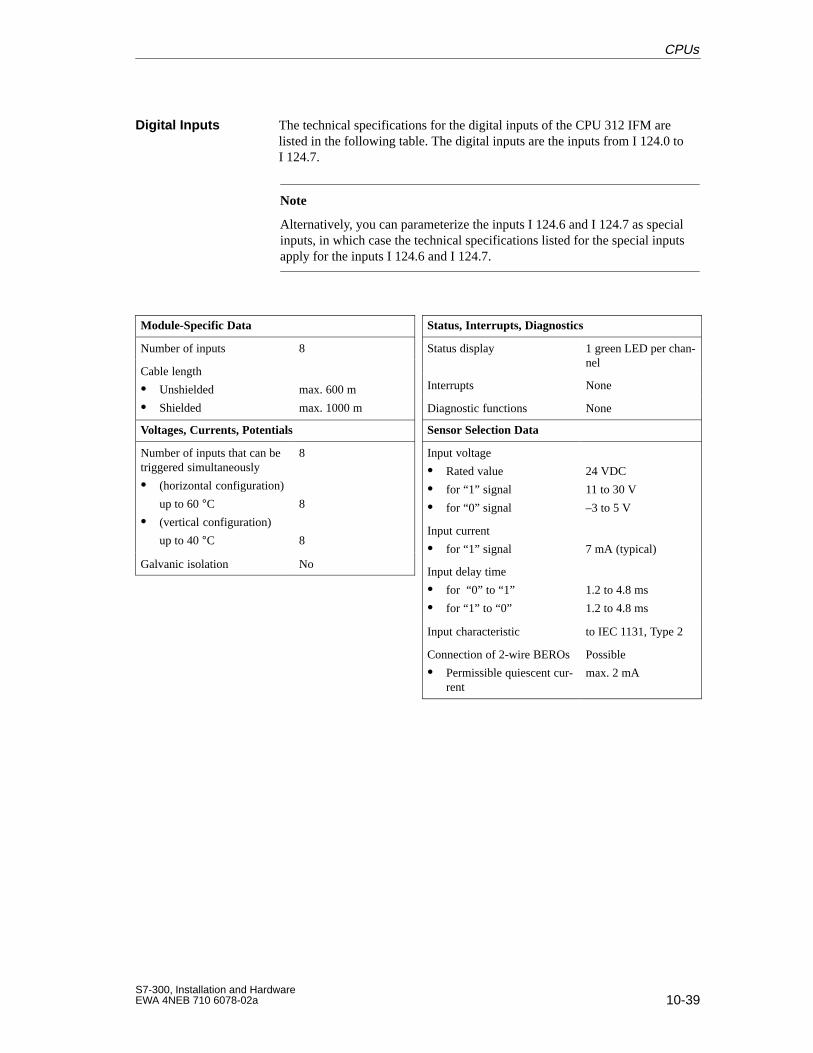
10-39S7-300, Installation and HardwareEWA 4NEB 710 6078-02a
The technical specifications for the digital inputs of the CPU 312 IFM arelisted in the following table. The digital inputs are the inputs from I 124.0 toI 124.7.
Note
Alternatively, you can parameterize the inputs I 124.6 and I 124.7 as specialinputs, in which case the technical specifications listed for the special inputsapply for the inputs I 124.6 and I 124.7.
Module-Specific Data
Number of inputs 8
Cable length
Unshielded
Shielded
max. 600 m
max. 1000 m
Voltages, Currents, Potentials
Number of inputs that can betriggered simultaneously
(horizontal configuration)
up to 60 °C (vertical configuration)
up to 40 °C
8
8
8
Galvanic isolation No
Status, Interrupts, Diagnostics
Status display 1 green LED per chan-nel
Interrupts None
Diagnostic functions None
Sensor Selection Data
Input voltage
Rated value
for “1” signal
for “0” signal
24 VDC
11 to 30 V
–3 to 5 V
Input current
for “1” signal 7 mA (typical)
Input delay time
for “0” to “1”
for “1” to “0”
1.2 to 4.8 ms
1.2 to 4.8 ms
Input characteristic to IEC 1131, Type 2
Connection of 2-wire BEROs
Permissible quiescent cur-rent
Possible
max. 2 mA
Digital Inputs
CPUs
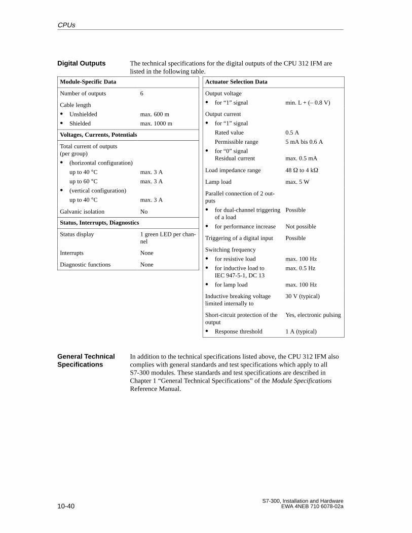
10-40S7-300, Installation and Hardware
EWA 4NEB 710 6078-02a
The technical specifications for the digital outputs of the CPU 312 IFM arelisted in the following table.
Module-Specific Data
Number of outputs 6
Cable length
Unshielded
Shielded
max. 600 m
max. 1000 m
Voltages, Currents, Potentials
Total current of outputs(per group)
(horizontal configuration)
up to 40 °Cup to 60 °C
(vertical configuration)
up to 40 °C
max. 3 A
max. 3 A
max. 3 A
Galvanic isolation No
Status, Interrupts, Diagnostics
Status display 1 green LED per chan-nel
Interrupts None
Diagnostic functions None
Actuator Selection Data
Output voltage
for “1” signal min. L + (– 0.8 V)
Output current
for “1” signal
Rated value
Permissible range
for “0” signal Residual current
0.5 A
5 mA bis 0.6 A
max. 0.5 mA
Load impedance range 48 to 4 k
Lamp load max. 5 W
Parallel connection of 2 out-puts
for dual-channel triggeringof a load
for performance increase
Possible
Not possible
Triggering of a digital input Possible
Switching frequency
for resistive load
for inductive load toIEC 947-5-1, DC 13
for lamp load
max. 100 Hz
max. 0.5 Hz
max. 100 Hz
Inductive breaking voltagelimited internally to
30 V (typical)
Short-citcuit protection of theoutput
Response threshold
Yes, electronic pulsing
1 A (typical)
In addition to the technical specifications listed above, the CPU 312 IFM alsocomplies with general standards and test specifications which apply to allS7-300 modules. These standards and test specifications are described inChapter 1 “General Technical Specifications” of the Module SpecificationsReference Manual.
Digital Outputs
General TechnicalSpecifications
CPUs
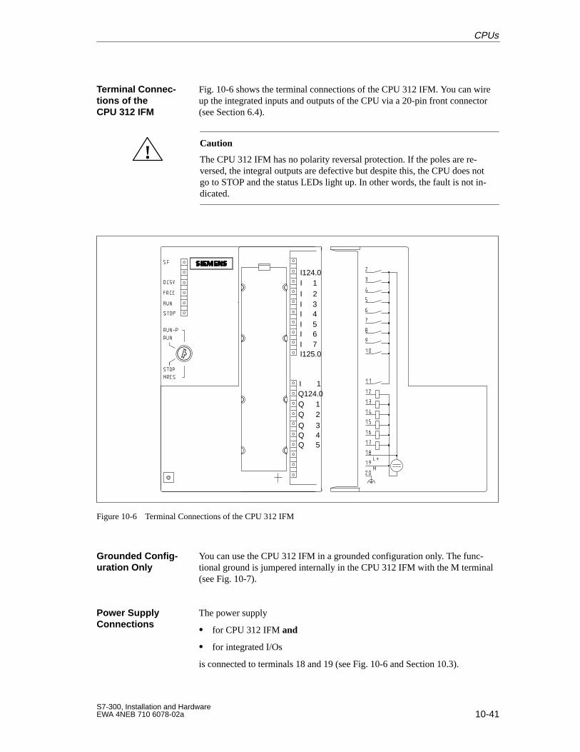
10-41S7-300, Installation and HardwareEWA 4NEB 710 6078-02a
Fig. 10-6 shows the terminal connections of the CPU 312 IFM. You can wireup the integrated inputs and outputs of the CPU via a 20-pin front connector(see Section 6.4).
!Caution
The CPU 312 IFM has no polarity reversal protection. If the poles are re-versed, the integral outputs are defective but despite this, the CPU does notgo to STOP and the status LEDs light up. In other words, the fault is not in-dicated.
I124.0I 1I 2I 3I 4I 5I 6I 7I125.0
I 1Q124.0Q 1
Q 3Q 2
Q 4Q 5
Figure 10-6 Terminal Connections of the CPU 312 IFM
You can use the CPU 312 IFM in a grounded configuration only. The func-tional ground is jumpered internally in the CPU 312 IFM with the M terminal(see Fig. 10-7).
The power supply
for CPU 312 IFM and
for integrated I/Os
is connected to terminals 18 and 19 (see Fig. 10-6 and Section 10.3).
Terminal Connec-tions of theCPU 312 IFM
Grounded Config-uration Only
Power SupplyConnections
CPUs
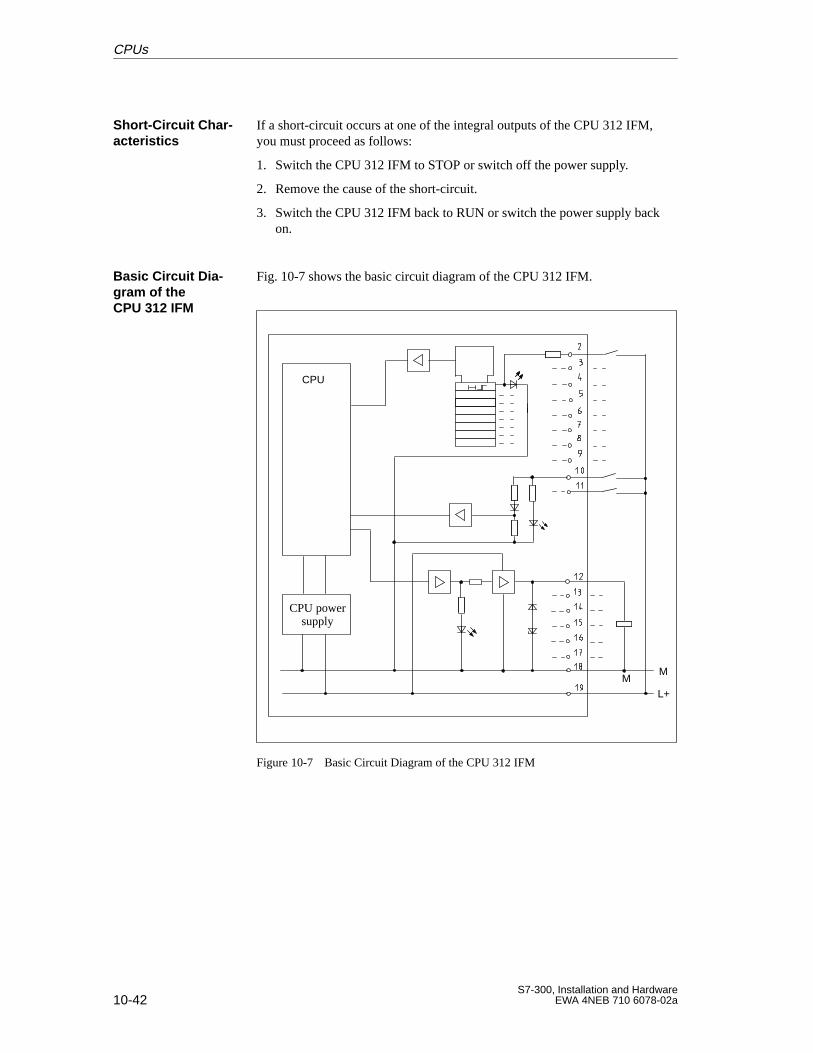
10-42S7-300, Installation and Hardware
EWA 4NEB 710 6078-02a
If a short-circuit occurs at one of the integral outputs of the CPU 312 IFM,you must proceed as follows:
1. Switch the CPU 312 IFM to STOP or switch off the power supply.
2. Remove the cause of the short-circuit.
3. Switch the CPU 312 IFM back to RUN or switch the power supply backon.
Fig. 10-7 shows the basic circuit diagram of the CPU 312 IFM.
CPU
CPU powersupply
M
L+M
Figure 10-7 Basic Circuit Diagram of the CPU 312 IFM
Short-Circuit Char-acteristics
Basic Circuit Dia -gram of theCPU 312 IFM
CPUs
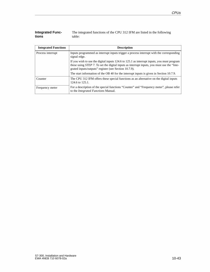
10-43S7-300, Installation and HardwareEWA 4NEB 710 6078-02a
The integrated functions of the CPU 312 IFM are listed in the followingtable:
Integrated Functions Description
Process interrupt Inputs programmed as interrupt inputs trigger a process interrupt with the correspondingsignal edge.
If you wish to use the digital inputs 124.6 to 125.1 as interrupt inputs, you must programthese using STEP 7. To set the digital inputs as interrupt inputs, you must use the “Inte-grated inputs/outputs” register (see Section 10.7.9).
The start information of the OB 40 for the interrupt inputs is given in Section 10.7.9.
Counter The CPU 312 IFM offers these special functions as an alternative on the digital inputs124.6 to 125.1.
Frequency meter For a description of the special functions “Counter” and “Frequency meter”, please referto the Integrated Functions Manual.
Integrated Func-tions
CPUs
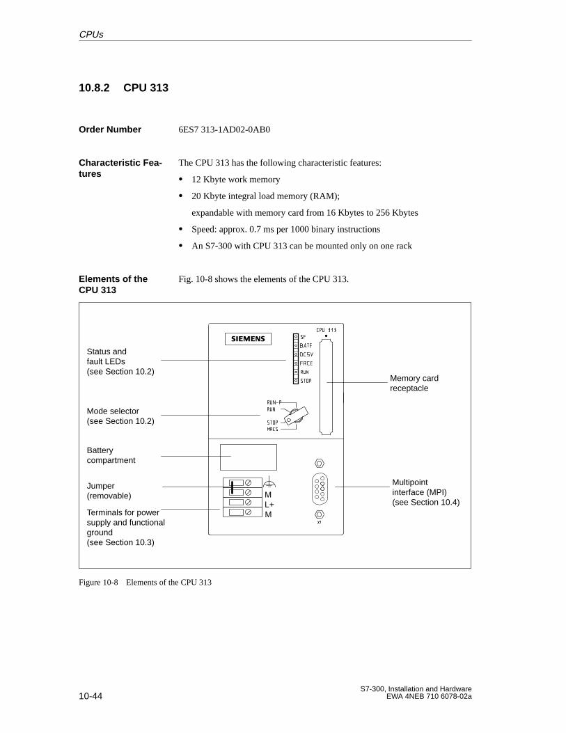
10-44S7-300, Installation and Hardware
EWA 4NEB 710 6078-02a
10.8.2 CPU 313
6ES7 313-1AD02-0AB0
The CPU 313 has the following characteristic features:
12 Kbyte work memory
20 Kbyte integral load memory (RAM);
expandable with memory card from 16 Kbytes to 256 Kbytes
Speed: approx. 0.7 ms per 1000 binary instructions
An S7-300 with CPU 313 can be mounted only on one rack
Fig. 10-8 shows the elements of the CPU 313.
Status andfault LEDs(see Section 10.2)
Mode selector(see Section 10.2)
Battery compartment
Terminals for powersupply and functionalground(see Section 10.3)
Multipoint interface (MPI)(see Section 10.4)
Memory cardreceptacle
ML+M
Jumper (removable)
Figure 10-8 Elements of the CPU 313
Order Number
Characteristic Fea -tures
Elements of theCPU 313
CPUs
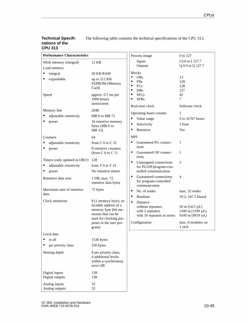
10-45S7-300, Installation and HardwareEWA 4NEB 710 6078-02a
The following table contains the technical specifications of the CPU 313.
Performance Characteristics
Work memory (integral)
Load memory
integral
expandable
12 KB
20 KB RAM
up to 512 KBFEPROM (MemoryCard)
Speed approx. 0.7 ms per1000 binaryinstructions
Memory bits
adjustable retentivity
preset
2048
MB 0 to MB 71
16 retentive memorybytes (MB 0 toMB 15)
Counters
adjustable retentivity
preset
64
from C 0 to C 31
8 retentive counters(from C 0 to C 7)
Timers (only updated in OB1!)
adjustable retentivity
preset
128
from T 0 to T 31
No retentive timers
Retentive data area 1 DB, max. 72retentive data bytes
Maximum sum of retentivedata
72 bytes
Clock memories 8 (1 memory byte); se-lectable address of amemory byte (bit me-mories that can beused for clocking pur-poses in the user pro-gram)
Local data
in all
per priority class
1536 bytes
256 bytes
Nesting depth 8 per priority class; 4 additional levels within a synchronouserror OB
Digital inputsDigital outputs
128128
Analog inputsAnalog outputs
3232
Process image
InputsOutputs
0 to 127
I 0.0 to I 127.7Q 0.0 to Q 127.7
Blocks OBs FBs FCs DBs SFCs SFBs
13128128127457
Real-time clock Software clock
Operating hours counter
Value range
Selectivity
Retentive
1
0 to 32767 hours
1 hour
Yes
MPI
Guaranteed PG connec-tions
Guaranteed OP connec-tions
Unassigned connectionsfor PG/OP/program-con-trolled communication
Guaranteed connectionsfor program-controlledcommunication
No. of nodes
Baudrate
Distancewithout repeaterswith 2 repeaterswith 10 repeaters in series
1
1
2
4
max. 32 nodes
19.2; 187.5 kbaud
50 m (54.5 yd.)1100 m (1199 yd.)9100 m (9919 yd.)
Configuration max. 8 modules on1 rack
Technical Specifi -cations of theCPU 313
CPUs
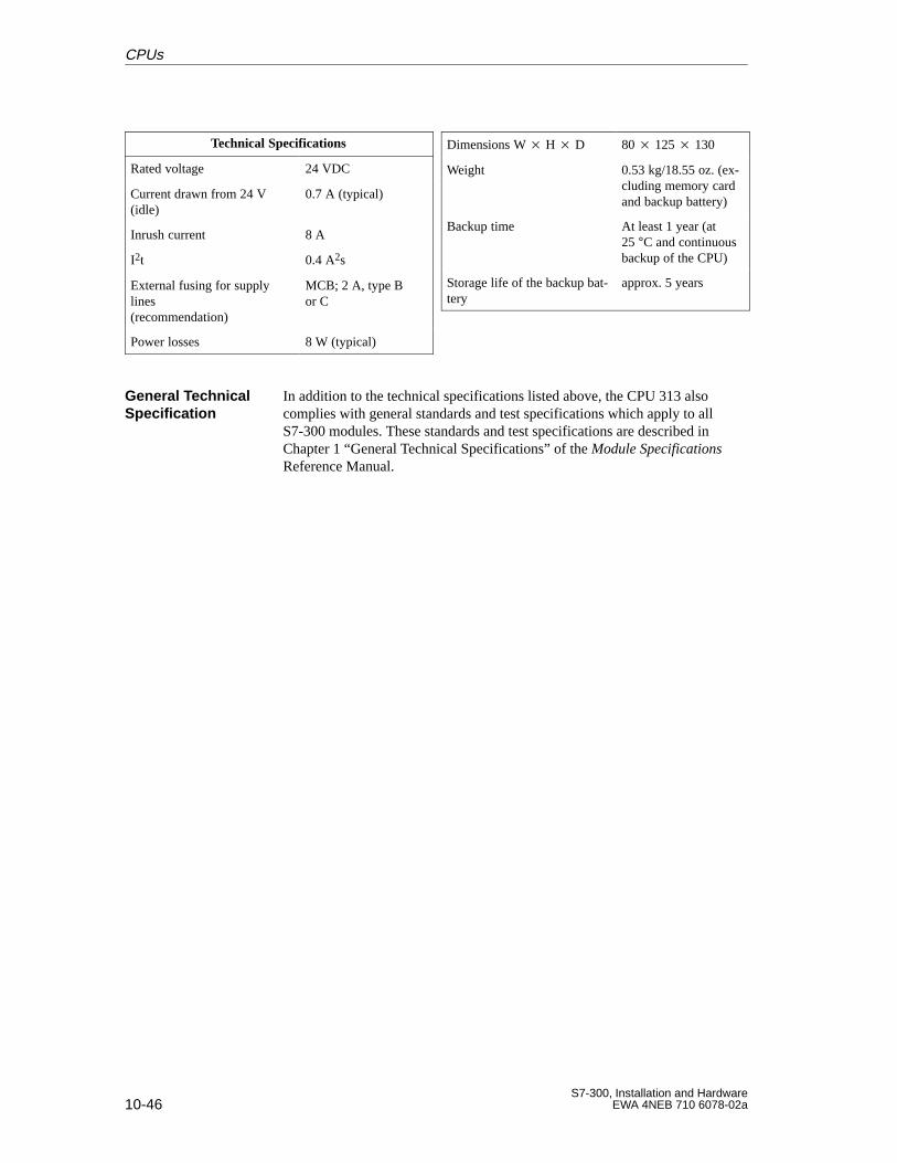
10-46S7-300, Installation and Hardware
EWA 4NEB 710 6078-02a
Technical Specifications
Rated voltage 24 VDC
Current drawn from 24 V(idle)
0.7 A (typical)
Inrush current 8 A
I2t 0.4 A2s
External fusing for supplylines (recommendation)
MCB; 2 A, type Bor C
Power losses 8 W (typical)
Dimensions W H D 80 125 130
Weight 0.53 kg/18.55 oz. (ex-cluding memory cardand backup battery)
Backup time At least 1 year (at25 °C and continuousbackup of the CPU)
Storage life of the backup bat-tery
approx. 5 years
In addition to the technical specifications listed above, the CPU 313 alsocomplies with general standards and test specifications which apply to allS7-300 modules. These standards and test specifications are described inChapter 1 “General Technical Specifications” of the Module SpecificationsReference Manual.
General TechnicalSpecification
CPUs
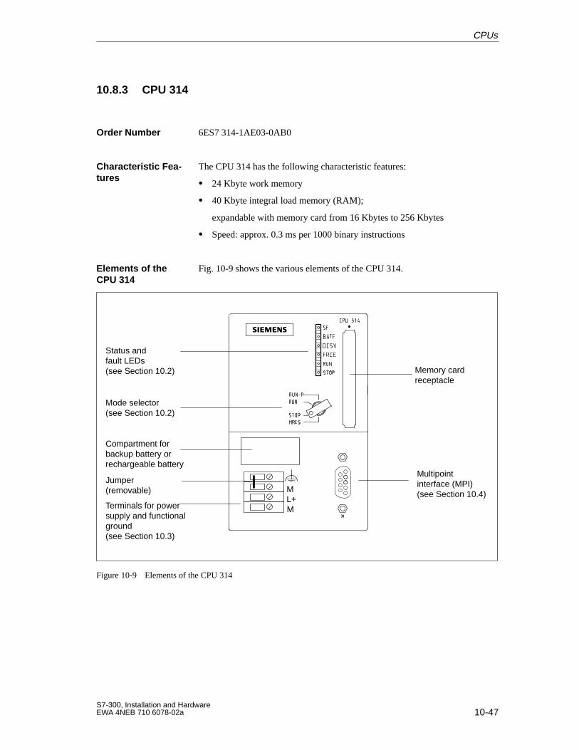
10-47S7-300, Installation and HardwareEWA 4NEB 710 6078-02a
10.8.3 CPU 314
6ES7 314-1AE03-0AB0
The CPU 314 has the following characteristic features:
24 Kbyte work memory
40 Kbyte integral load memory (RAM);
expandable with memory card from 16 Kbytes to 256 Kbytes
Speed: approx. 0.3 ms per 1000 binary instructions
Fig. 10-9 shows the various elements of the CPU 314.
Status andfault LEDs(see Section 10.2)
Mode selector(see Section 10.2)
Compartment forbackup battery or rechargeable battery
Terminals for powersupply and functionalground(see Section 10.3)
Multipoint interface (MPI)(see Section 10.4)
Memory cardreceptacle
ML+M
Jumper (removable)
Figure 10-9 Elements of the CPU 314
Order Number
Characteristic Fea -tures
Elements of theCPU 314
CPUs
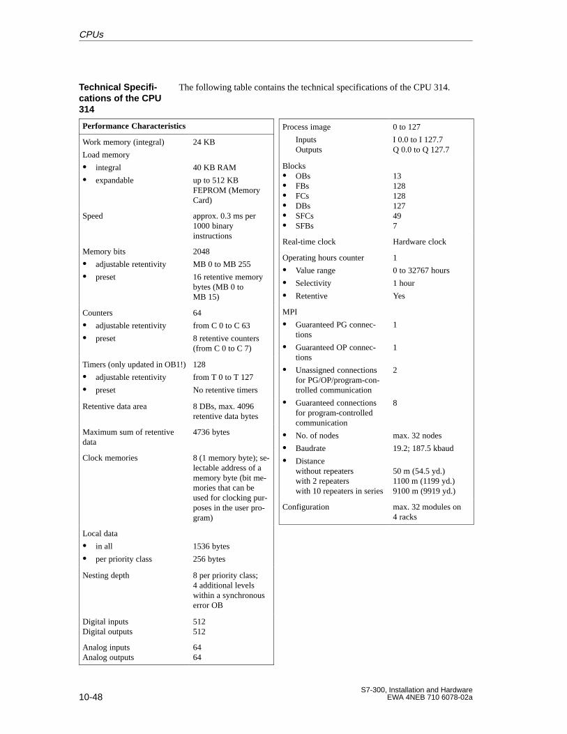
10-48S7-300, Installation and Hardware
EWA 4NEB 710 6078-02a
The following table contains the technical specifications of the CPU 314.
Performance Characteristics
Work memory (integral)
Load memory
integral
expandable
24 KB
40 KB RAM
up to 512 KBFEPROM (MemoryCard)
Speed approx. 0.3 ms per1000 binaryinstructions
Memory bits
adjustable retentivity
preset
2048
MB 0 to MB 255
16 retentive memorybytes (MB 0 toMB 15)
Counters
adjustable retentivity
preset
64
from C 0 to C 63
8 retentive counters(from C 0 to C 7)
Timers (only updated in OB1!)
adjustable retentivity
preset
128
from T 0 to T 127
No retentive timers
Retentive data area 8 DBs, max. 4096retentive data bytes
Maximum sum of retentivedata
4736 bytes
Clock memories 8 (1 memory byte); se-lectable address of amemory byte (bit me-mories that can beused for clocking pur-poses in the user pro-gram)
Local data
in all
per priority class
1536 bytes
256 bytes
Nesting depth 8 per priority class; 4 additional levels within a synchronouserror OB
Digital inputsDigital outputs
512512
Analog inputsAnalog outputs
6464
Process image
InputsOutputs
0 to 127
I 0.0 to I 127.7Q 0.0 to Q 127.7
Blocks OBs FBs FCs DBs SFCs SFBs
13128128127497
Real-time clock Hardware clock
Operating hours counter
Value range
Selectivity
Retentive
1
0 to 32767 hours
1 hour
Yes
MPI
Guaranteed PG connec-tions
Guaranteed OP connec-tions
Unassigned connectionsfor PG/OP/program-con-trolled communication
Guaranteed connectionsfor program-controlledcommunication
No. of nodes
Baudrate
Distancewithout repeaterswith 2 repeaterswith 10 repeaters in series
1
1
2
8
max. 32 nodes
19.2; 187.5 kbaud
50 m (54.5 yd.)1100 m (1199 yd.)9100 m (9919 yd.)
Configuration max. 32 modules on4 racks
Technical Specifi -cations of the CPU314
CPUs
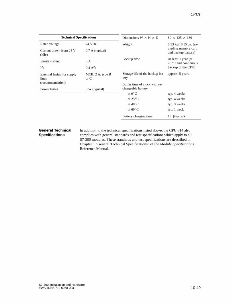
10-49S7-300, Installation and HardwareEWA 4NEB 710 6078-02a
Technical Specifications
Rated voltage 24 VDC
Current drawn from 24 V(idle)
0.7 A (typical)
Inrush current 8 A
I2t 0.4 A2s
External fusing for supplylines (recommendation)
MCB; 2 A, type Bor C
Power losses 8 W (typical)
Dimensions W H D 80 125 130
Weight 0.53 kg/18.55 oz. (ex-cluding memory cardand backup battery)
Backup time At least 1 year (at 25 °C and continuousbackup of the CPU)
Storage life of the backup bat-tery
approx. 5 years
Buffer time of clock with re-chargeable battery
at 0C
at 25C
at 40C
at 60C
typ. 4 weeks
typ. 4 weeks
typ. 3 weeks
typ. 1 week
Battery charging time 1 h (typical)
In addition to the technical specifications listed above, the CPU 314 alsocomplies with general standards and test specifications which apply to allS7-300 modules. These standards and test specifications are described inChapter 1 “General Technical Specifications” of the Module SpecificationsReference Manual.
General TechnicalSpecifications
CPUs
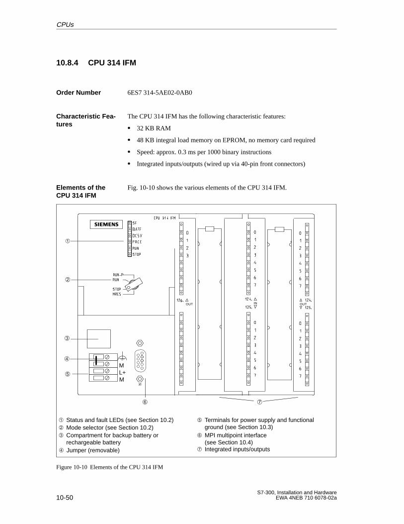
10-50S7-300, Installation and Hardware
EWA 4NEB 710 6078-02a
10.8.4 CPU 314 IFM
6ES7 314-5AE02-0AB0
The CPU 314 IFM has the following characteristic features:
32 KB RAM
48 KB integral load memory on EPROM, no memory card required
Speed: approx. 0.3 ms per 1000 binary instructions
Integrated inputs/outputs (wired up via 40-pin front connectors)
Fig. 10-10 shows the various elements of the CPU 314 IFM.
IN OUTOUT
ML+M
Status and fault LEDs (see Section 10.2) Mode selector (see Section 10.2) Compartment for backup battery or
rechargeable battery Jumper (removable)
Terminals for power supply and functional ground (see Section 10.3)
MPI multipoint interface (see Section 10.4)
Integrated inputs/outputs
Figure 10-10 Elements of the CPU 314 IFM
Order Number
Characteristic Fea -tures
Elements of theCPU 314 IFM
CPUs
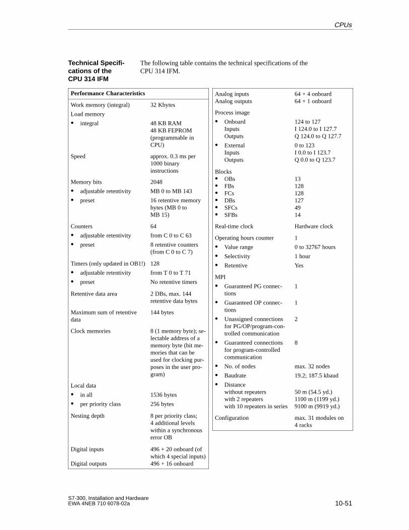
10-51S7-300, Installation and HardwareEWA 4NEB 710 6078-02a
The following table contains the technical specifications of theCPU 314 IFM.
Performance Characteristics
Work memory (integral)
Load memory
integral
32 Kbytes
48 KB RAM48 KB FEPROM(programmable inCPU)
Speed approx. 0.3 ms per1000 binaryinstructions
Memory bits
adjustable retentivity
preset
2048
MB 0 to MB 143
16 retentive memorybytes (MB 0 toMB 15)
Counters
adjustable retentivity
preset
64
from C 0 to C 63
8 retentive counters(from C 0 to C 7)
Timers (only updated in OB1!)
adjustable retentivity
preset
128
from T 0 to T 71
No retentive timers
Retentive data area 2 DBs, max. 144retentive data bytes
Maximum sum of retentivedata
144 bytes
Clock memories 8 (1 memory byte); se-lectable address of amemory byte (bit me-mories that can beused for clocking pur-poses in the user pro-gram)
Local data
in all
per priority class
1536 bytes
256 bytes
Nesting depth 8 per priority class;4 additional levelswithin a synchronouserror OB
Digital inputs
Digital outputs
496 + 20 onboard (ofwhich 4 special inputs)496 + 16 onboard
Analog inputsAnalog outputs
64 + 4 onboard64 + 1 onboard
Process image
OnboardInputs Outputs
ExternalInputs Outputs
124 to 127I 124.0 to I 127.7Q 124.0 to Q 127.7
0 to 123I 0.0 to I 123.7Q 0.0 to Q 123.7
Blocks OBs FBs FCs DBs SFCs SFBs
131281281274914
Real-time clock Hardware clock
Operating hours counter
Value range
Selectivity
Retentive
1
0 to 32767 hours
1 hour
Yes
MPI
Guaranteed PG connec-tions
Guaranteed OP connec-tions
Unassigned connectionsfor PG/OP/program-con-trolled communication
Guaranteed connectionsfor program-controlledcommunication
No. of nodes
Baudrate
Distancewithout repeaterswith 2 repeaterswith 10 repeaters in series
1
1
2
8
max. 32 nodes
19.2; 187.5 kbaud
50 m (54.5 yd.)1100 m (1199 yd.)9100 m (9919 yd.)
Configuration max. 31 modules on4 racks
Technical Specifi -cations of theCPU 314 IFM
CPUs
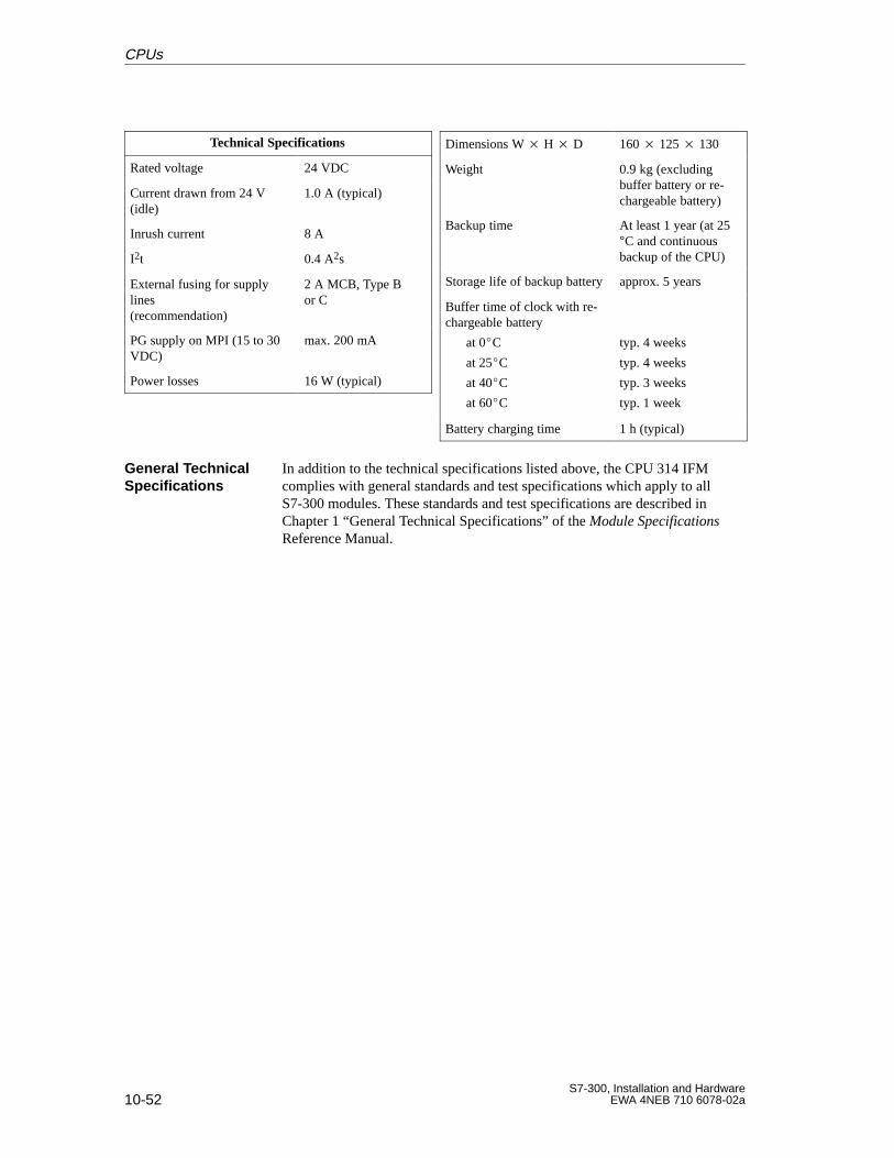
10-52S7-300, Installation and Hardware
EWA 4NEB 710 6078-02a
Technical Specifications
Rated voltage 24 VDC
Current drawn from 24 V(idle)
1.0 A (typical)
Inrush current 8 A
I2t 0.4 A2s
External fusing for supplylines (recommendation)
2 A MCB, Type Bor C
PG supply on MPI (15 to 30VDC)
max. 200 mA
Power losses 16 W (typical)
Dimensions W H D 160 125 130
Weight 0.9 kg (excludingbuffer battery or re-chargeable battery)
Backup time At least 1 year (at 25°C and continuousbackup of the CPU)
Storage life of backup battery approx. 5 years
Buffer time of clock with re-chargeable battery
at 0C
at 25C
at 40C
at 60C
typ. 4 weeks
typ. 4 weeks
typ. 3 weeks
typ. 1 week
Battery charging time 1 h (typical)
In addition to the technical specifications listed above, the CPU 314 IFMcomplies with general standards and test specifications which apply to allS7-300 modules. These standards and test specifications are described inChapter 1 “General Technical Specifications” of the Module SpecificationsReference Manual.
General TechnicalSpecifications
CPUs
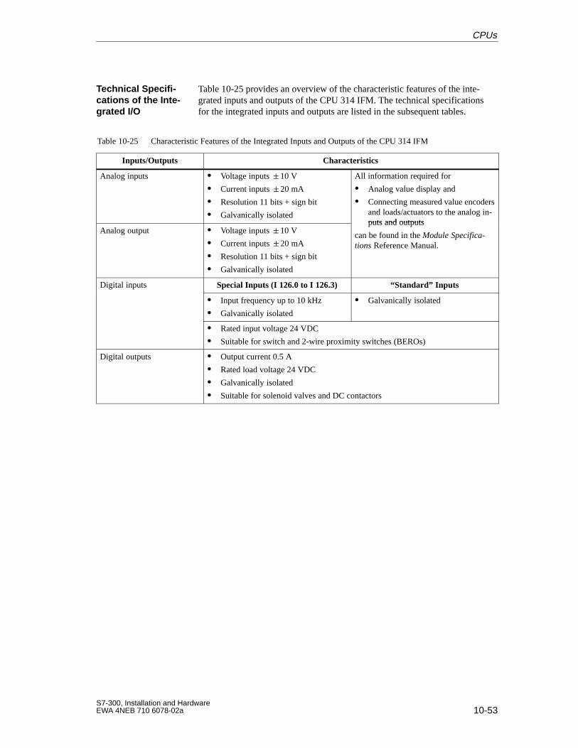
10-53S7-300, Installation and HardwareEWA 4NEB 710 6078-02a
Table 10-25 provides an overview of the characteristic features of the inte-grated inputs and outputs of the CPU 314 IFM. The technical specificationsfor the integrated inputs and outputs are listed in the subsequent tables.
Table 10-25 Characteristic Features of the Integrated Inputs and Outputs of the CPU 314 IFM
Inputs/Outputs Characteristics
Analog inputs Voltage inputs 10 V
Current inputs 20 mA
Resolution 11 bits + sign bit
Galvanically isolated
All information required for
Analog value display and
Connecting measured value encodersand loads/actuators to the analog in-puts and outputs
Analog output Voltage inputs 10 V
Current inputs 20 mA
Resolution 11 bits + sign bit
Galvanically isolated
puts and outputs
can be found in the Module Specifica-tions Reference Manual.
Digital inputs Special Inputs (I 126.0 to I 126.3) “Standard” Inputsg p
Input frequency up to 10 kHz
Galvanically isolated
Galvanically isolated
Rated input voltage 24 VDC
Suitable for switch and 2-wire proximity switches (BEROs)
Digital outputs Output current 0.5 A
Rated load voltage 24 VDC
Galvanically isolated
Suitable for solenoid valves and DC contactors
Technical Specifi -cations of the Inte-grated I/O
CPUs
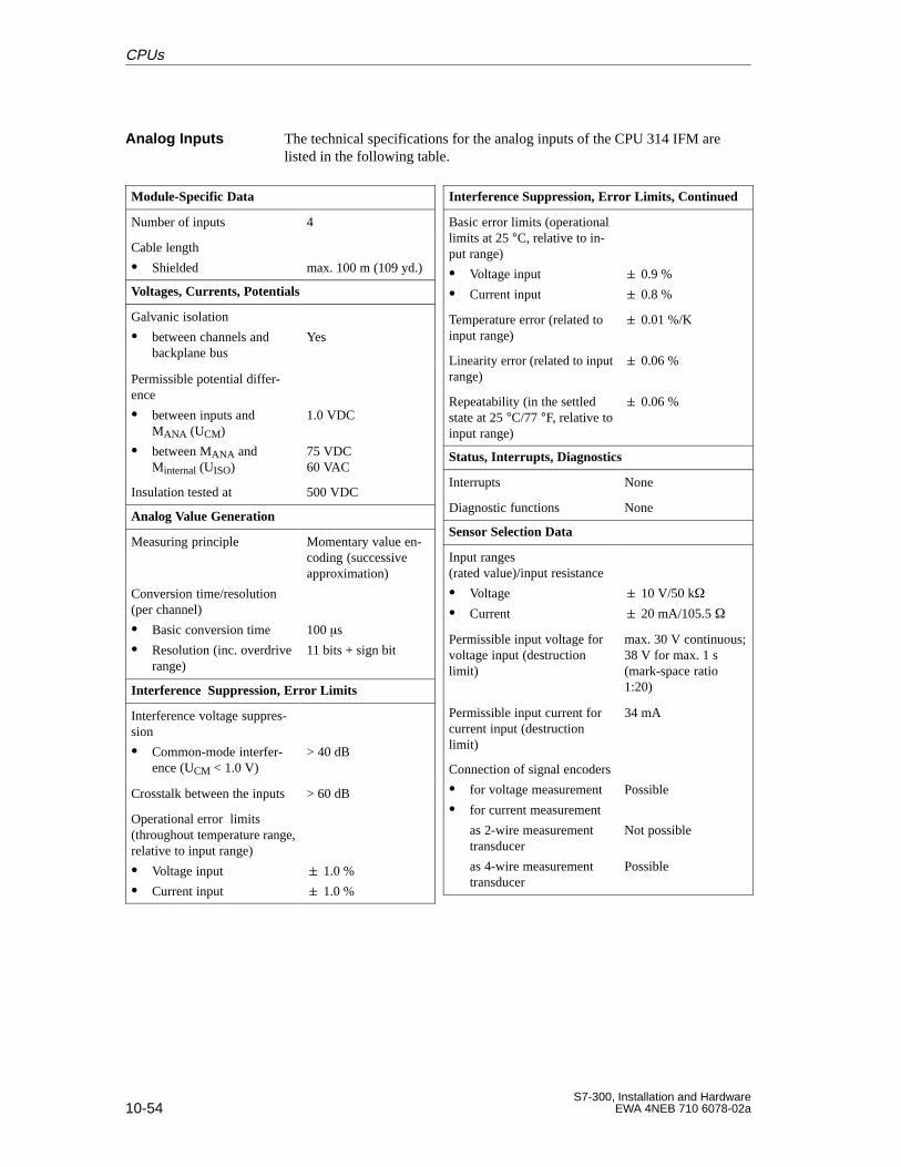
10-54S7-300, Installation and Hardware
EWA 4NEB 710 6078-02a
The technical specifications for the analog inputs of the CPU 314 IFM arelisted in the following table.
Module-Specific Data
Number of inputs 4
Cable length
Shielded max. 100 m (109 yd.)
Voltages, Currents, Potentials
Galvanic isolation
between channels andbackplane bus
Yes
Permissible potential differ-ence
between inputs and MANA (UCM)
between MANA andMinternal (UISO)
1.0 VDC
75 VDC60 VAC
Insulation tested at 500 VDC
Analog Value Generation
Measuring principle
Conversion time/resolution(per channel)
Basic conversion time
Resolution (inc. overdriverange)
Momentary value en-coding (successiveapproximation)
100 s
11 bits + sign bit
Interference Suppression, Error Limits
Interference voltage suppres-sion
Common-mode interfer-ence (UCM < 1.0 V)
> 40 dB
Crosstalk between the inputs > 60 dB
Operational error limits(throughout temperature range,relative to input range)
Voltage input
Current input
1.0 %
1.0 %
Interference Suppression, Error Limits, Continued
Basic error limits (operationallimits at 25 °C, relative to in-put range)
Voltage input
Current input
0.9 %
0.8 %
Temperature error (related toinput range)
0.01 %/K
Linearity error (related to inputrange)
0.06 %
Repeatability (in the settledstate at 25 °C/77 °F, relative toinput range)
0.06 %
Status, Interrupts, Diagnostics
Interrupts None
Diagnostic functions None
Sensor Selection Data
Input ranges(rated value)/input resistance
Voltage
Current
10 V/50 k
20 mA/105.5
Permissible input voltage forvoltage input (destructionlimit)
max. 30 V continuous;38 V for max. 1 s(mark-space ratio1:20)
Permissible input current forcurrent input (destructionlimit)
34 mA
Connection of signal encoders
for voltage measurement
for current measurement
as 2-wire measurementtransducer
as 4-wire measurementtransducer
Possible
Not possible
Possible
Analog Inputs
CPUs
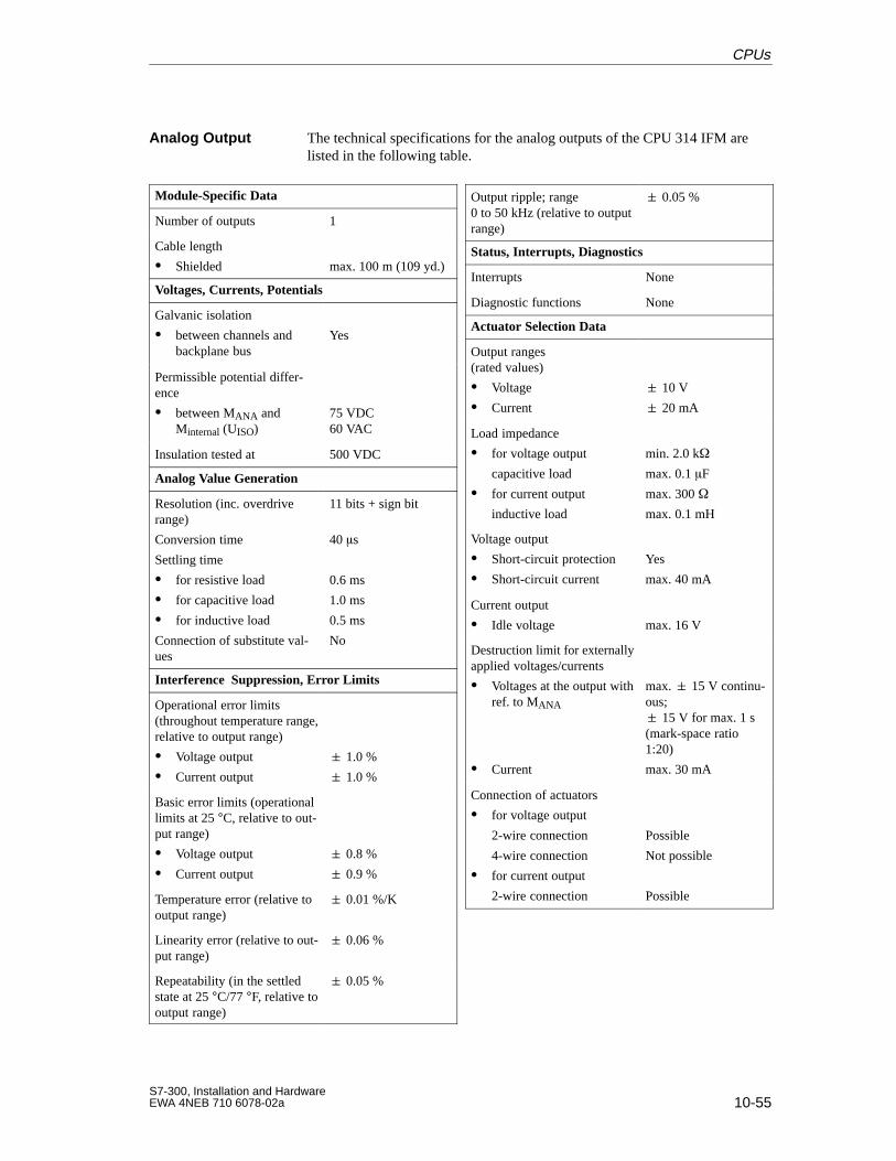
10-55S7-300, Installation and HardwareEWA 4NEB 710 6078-02a
The technical specifications for the analog outputs of the CPU 314 IFM arelisted in the following table.
Module-Specific Data
Number of outputs 1
Cable length
Shielded max. 100 m (109 yd.)
Voltages, Currents, Potentials
Galvanic isolation
between channels andbackplane bus
Yes
Permissible potential differ-ence
between MANA andMinternal (UISO)
75 VDC60 VAC
Insulation tested at 500 VDC
Analog Value Generation
Resolution (inc. overdriverange)
Conversion time
Settling time
for resistive load
for capacitive load
for inductive load
Connection of substitute val-ues
11 bits + sign bit
40 s
0.6 ms
1.0 ms
0.5 ms
No
Interference Suppression, Error Limits
Operational error limits(throughout temperature range,relative to output range)
Voltage output
Current output
1.0 %
1.0 %
Basic error limits (operationallimits at 25 °C, relative to out-put range)
Voltage output
Current output
0.8 %
0.9 %
Temperature error (relative tooutput range)
0.01 %/K
Linearity error (relative to out-put range)
0.06 %
Repeatability (in the settledstate at 25 °C/77 °F, relative tooutput range)
0.05 %
Output ripple; range0 to 50 kHz (relative to outputrange)
0.05 %
Status, Interrupts, Diagnostics
Interrupts None
Diagnostic functions None
Actuator Selection Data
Output ranges (rated values)
Voltage
Current
10 V
20 mA
Load impedance
for voltage output
capacitive load
for current output
inductive load
min. 2.0 k
max. 0.1 F
max. 300
max. 0.1 mH
Voltage output
Short-circuit protection
Short-circuit current
Yes
max. 40 mA
Current output
Idle voltage max. 16 V
Destruction limit for externallyapplied voltages/currents
Voltages at the output withref. to MANA
Current
max. 15 V continu-ous; 15 V for max. 1 s(mark-space ratio1:20)
max. 30 mA
Connection of actuators
for voltage output
2-wire connection
4-wire connection
for current output
2-wire connection
Possible
Not possible
Possible
Analog Output
CPUs
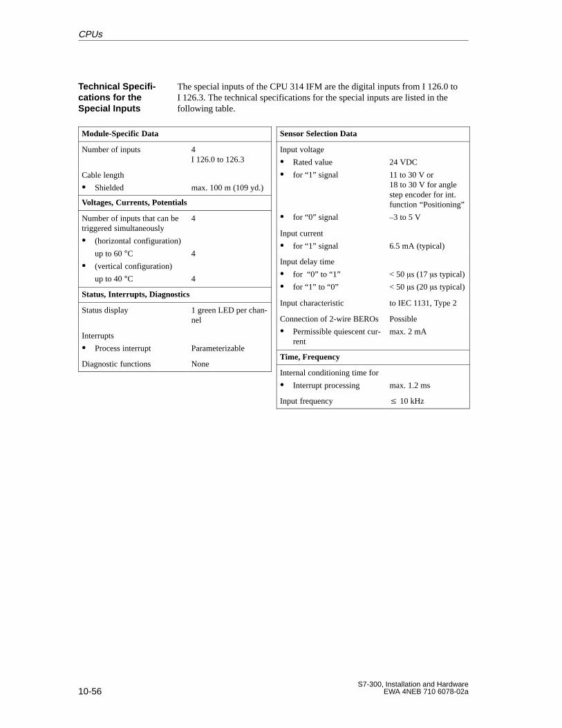
10-56S7-300, Installation and Hardware
EWA 4NEB 710 6078-02a
The special inputs of the CPU 314 IFM are the digital inputs from I 126.0 toI 126.3. The technical specifications for the special inputs are listed in thefollowing table.
Module-Specific Data
Number of inputs 4I 126.0 to 126.3
Cable length
Shielded max. 100 m (109 yd.)
Voltages, Currents, Potentials
Number of inputs that can betriggered simultaneously
(horizontal configuration)
up to 60 °C (vertical configuration)
up to 40 °C
4
4
4
Status, Interrupts, Diagnostics
Status display 1 green LED per chan-nel
Interrupts
Process interrupt Parameterizable
Diagnostic functions None
Sensor Selection Data
Input voltage
Rated value
for “1” signal
for “0” signal
24 VDC
11 to 30 V or18 to 30 V for anglestep encoder for int.function “Positioning”
–3 to 5 V
Input current
for “1” signal 6.5 mA (typical)
Input delay time
for “0” to “1”
for “1” to “0”
< 50 s (17 s typical)
< 50 s (20 s typical)
Input characteristic to IEC 1131, Type 2
Connection of 2-wire BEROs
Permissible quiescent cur-rent
Possible
max. 2 mA
Time, Frequency
Internal conditioning time for
Interrupt processing max. 1.2 ms
Input frequency 10 kHz
Technical Specifi -cations for theSpecial Inputs
CPUs
10-57S7-300, Installation and HardwareEWA 4NEB 710 6078-02a
The technical specifications for the digital inputs of the CPU 314 IFM arelisted in the following table.
Module-Specific Data
Number of inputs 16
Cable length
Unshielded
Shielded
max. 600 m
max. 1000 m
Voltages, Currents, Potentials
Rated load current L+
Polarity reversal protection
24 VDC
Yes
Number of inputs that can betriggered simultaneously
(horizontal configuration)
up to 60 °C (vertical configuration)
up to 40 °C
16
16
16
Galvanic isolation
between channels andbackplane bus
Yes
Permissible potential differ-ence
between different circuits75 VDC60 VAC
Insulation tested at 500 VDC
Current consumption
from L+ supply max. 40 mA
Status, Interrupts, Diagnostics
Status display 1 green LED per chan-nel
Interrupts None
Diagnostic functions None
Sensor Selection Data
Input voltage
Rated value
for “1” signal
for “0” signal
24 VDC
11 to 30 V
–3 to 5 V
Input current
for “1” signal 7 mA (typical)
Input delay time
for “0” to “1”
for “1” to “0”
1.2 to 4.8 ms
1.2 to 4.8 ms
Input characteristic to IEC 1131, Type 2
Connection of 2-wire BEROs
Permissible quiescent cur-rent
Possible
max. 2 mA
The technical specifications for the digital outputs of the CPU 314 IFM arelisted in the following table.
When the supply voltage is switched on a pulse occurs on the digital outputs!This can be s long within the permissible output current range. You mustnot, therefore, use the digital outputs to trigger high-speed counters.
Digital Inputs
Digital Outputs
Note
CPUs
10-58S7-300, Installation and Hardware
EWA 4NEB 710 6078-02a
Module-Specific Data
Number of outputs 16
Cable length
Unshielded
Shielded
max. 600 m
max. 1000 m
Voltages, Currents, Potentials
Rated load current L+
Polarity reversal protection
24 VDC
No
Total current of outputs(per group)
(horizontal configuration)
up to 40 °Cup to 60 °C
(vertical configuration)
up to 40 °C
max. 4 A
max. 2 A
max. 2 A
Galvanic isolation
between channels andbackplane bus
between the channels
in groups of
Yes
Yes
8
Permissible potential differ-ence
between different circuits75 VDC60 VAC
Insulation tested at 500 VDC
Current consumption
from L+ supply (no-load) max. 100 mA
Status, Interrupts, Diagnostics
Status display 1 green LED per chan-nel
Interrupts None
Diagnostic functions None
Actuator Selection Data
Output voltage
for “1” signal min. L + (– 0.8 V)
Output current
for “1” signal
Rated value
Permissible range
for “0” signal(residual current)
0.5 A
5 mA bis 0.6 A
max. 0.5 mA
Load impedance range 48 to 4 k
Lgep load max. 5 W
Parallel connection of 2 out-puts
for dual-channel triggeringof a load
for performance increase
Possible, only outputsof the same group
Not possible
Triggering of a digital input Possible
Switching frequency
for resistive load
for inductive load toIEC 947-5-1, DC 13
for lamp load
max. 100 Hz
max. 0.5 Hz
max. 100 Hz
Inductive breaking voltagelimited internally to
L+ (– 48 V) typical
Short-citcuit protection of theoutput
Response threshold
Yes, electronic pulsing
1 A (typical)
CPUs
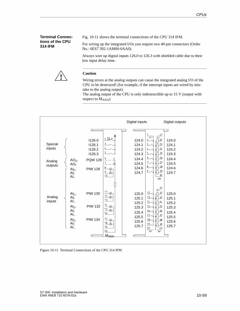
10-59S7-300, Installation and HardwareEWA 4NEB 710 6078-02a
Fig. 10-11 shows the terminal connections of the CPU 314 IFM.
For wiring up the integrated I/Os you require two 40-pin connectors (OrderNo.: 6ES7 392-1AM00-0AA0).
Always wire up digital inputs 126.0 to 126.3 with shielded cable due to theirlow input delay time.
!Caution
Wiring errors at the analog outputs can cause the integrated analog I/O of theCPU to be destroyed! (for example, if the interrupt inputs are wired by mis-take to the analog output).The analog output of the CPU is only indestructible up to 15 V (output withrespect to MANA).
1M
1L+
3L+
3M
2L+
2M
1L+
MANA
Special inputs
Analog outputs
Analog inputs
I126.0I126.1I126.2I126.3
PQW 128
PIW 128
PIW 130
PIW 132
PIW 134
AOUAOI
AIUAIIAI–
AIUAIIAI–AIUAIIAI–AIUAIIAI–
124.0124.1124.2124.3124.4124.5124.6124.7
125.0125.1125.2125.3125.4125.5125.6125.7
124.0124.1124.2124.3124.4124.5124.6124.7
125.0125.1125.2125.3125.4125.5125.6125.7
Digital inputs Digital outputs
Figure 10-11 Terminal Connections of the CPU 314 IFM
Terminal Connec-tions of the CPU314 IFM
CPUs
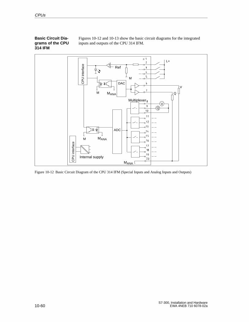
10-60S7-300, Installation and Hardware
EWA 4NEB 710 6078-02a
Figures 10-12 and 10-13 show the basic circuit diagrams for the integratedinputs and outputs of the CPU 314 IFM.
L+
DAC
Internal supply
+ Ref
M
ADC
VQ
MANA
MANA
Multiplexer
V
Q
MANA
CP
U in
terf
ace
CP
U in
terf
ace
M
M
Figure 10-12 Basic Circuit Diagram of the CPU 314 IFM (Special Inputs and Analog Inputs and Outputs)
Basic Circuit Dia -grams of the CPU314 IFM
CPUs
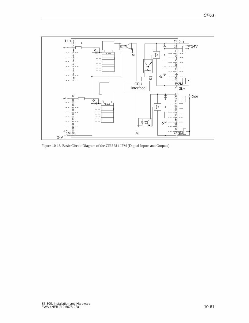
10-61S7-300, Installation and HardwareEWA 4NEB 710 6078-02a
1 L+
CPUinterface
24V1M M
2L+
M
2M
3M
24V
24V
3L+
M
Figure 10-13 Basic Circuit Diagram of the CPU 314 IFM (Digital Inputs and Outputs)
CPUs
10-62S7-300, Installation and Hardware
EWA 4NEB 710 6078-02a
The integrated functions of the CPU 314 IFM are listed in the followingtable:
Integrated Functions Description
Process interrupt Inputs programmed as interrupt inputs trigger a process interrupt with thecorresponding signal edge. If you wish to use the digital inputs 126.0 to 126.3as interrupt inputs, you must program these using STEP 7. To set the digitalinputs as interrupt inputs, you must use the “Integrated inputs/outputs” regis-ter (see Section 10.7.9).
The start information for OB 40 of the interrupt inputs is given in Sec-tion 10.7.9.
Note: To prevent lengthening of the interrupt reaction times for the CPU, youshould address the analog inputs of the CPU separately in the user programusing L PIW. Double-word addressing can lengthen the access times by up to200 s!
Counter The CPU 314 IFM offers these special functions as an alternative on digitali t 126 0 t 126 3 F d i ti f th i l f ti lFrequency meter
p ginputs 126.0 to 126.3. For a description of these special functions, please re-fer to theIntegrated FunctionsManual
Counter A/Bfer to the Integrated Functions Manual.
Positioning
CONT_C These functions are not restricted to specific inputs and outputs of the CPU314 IFM F d i ti f th f ti l f t th S t dCONT_S
p p p314 IFM. For a description of these functions, please refer to the System andStandard FunctionsReference Manual
PULSEGENStandard Functions Reference Manual.
Integrated Func-tions
CPUs
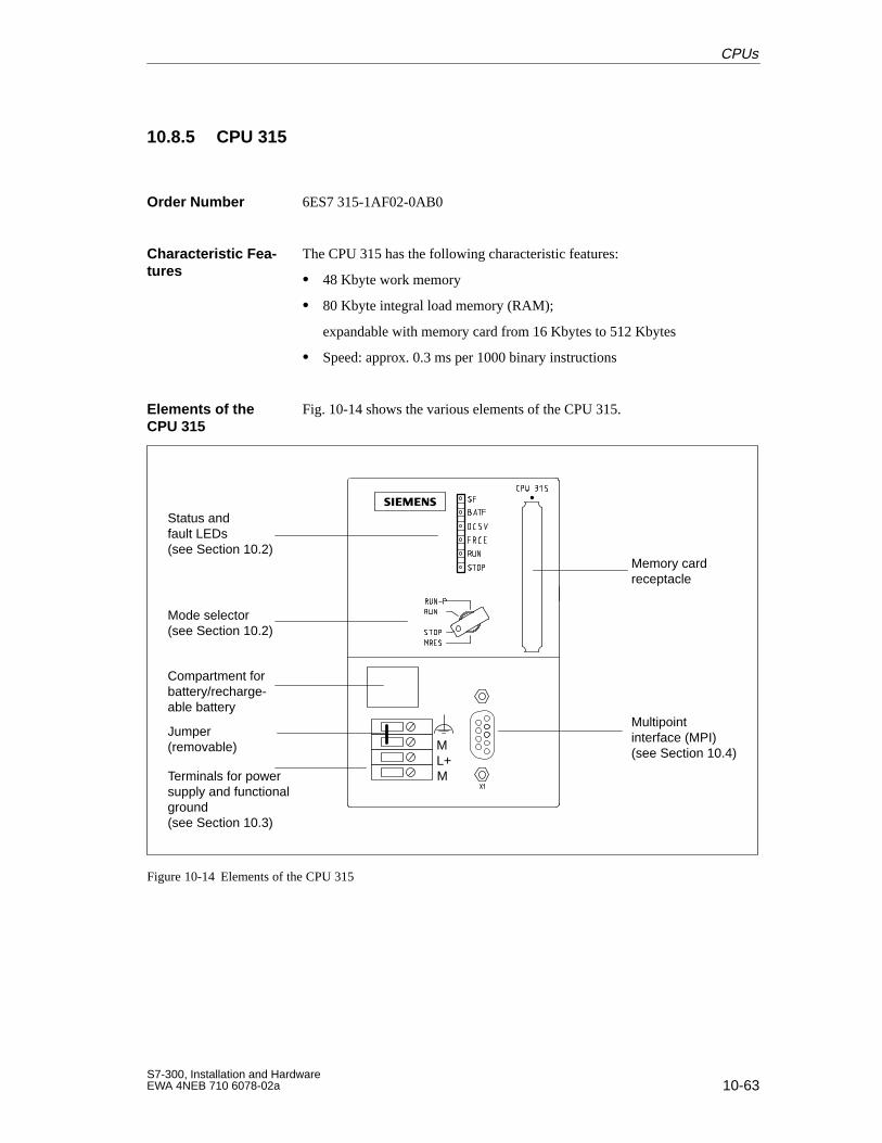
10-63S7-300, Installation and HardwareEWA 4NEB 710 6078-02a
10.8.5 CPU 315
6ES7 315-1AF02-0AB0
The CPU 315 has the following characteristic features:
48 Kbyte work memory
80 Kbyte integral load memory (RAM);
expandable with memory card from 16 Kbytes to 512 Kbytes
Speed: approx. 0.3 ms per 1000 binary instructions
Fig. 10-14 shows the various elements of the CPU 315.
Memory cardreceptacle
Compartment forbattery/recharge-able battery
ML+M
Jumper (removable)
Status andfault LEDs(see Section 10.2)
Mode selector(see Section 10.2)
Terminals for powersupply and functionalground(see Section 10.3)
Multipoint interface (MPI)(see Section 10.4)
Figure 10-14 Elements of the CPU 315
Order Number
Characteristic Fea -tures
Elements of theCPU 315
CPUs
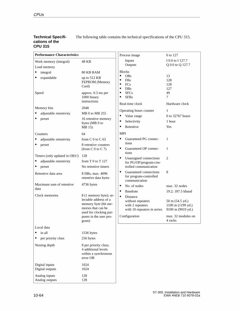
10-64S7-300, Installation and Hardware
EWA 4NEB 710 6078-02a
The following table contains the technical specifications of the CPU 315.
Performance Characteristics
Work memory (integral)
Load memory
integral
expandable
48 KB
80 KB RAM
up to 512 KBFEPROM (MemoryCard)
Speed approx. 0.3 ms per1000 binaryinstructions
Memory bits
adjustable retentivity
preset
2048
MB 0 to MB 255
16 retentive memorybytes (MB 0 toMB 15)
Counters
adjustable retentivity
preset
64
from C 0 to C 63
8 retentive counters(from C 0 to C 7)
Timers (only updated in OB1!)
adjustable retentivity
preset
128
from T 0 to T 127
No retentive timers
Retentive data area 8 DBs, max. 4096retentive data bytes
Maximum sum of retentivedata
4736 bytes
Clock memories 8 (1 memory byte); se-lectable address of amemory byte (bit me-mories that can beused for clocking pur-poses in the user pro-gram)
Local data
in all
per priority class
1536 bytes
256 bytes
Nesting depth 8 per priority class;4 additional levels within a synchronouserror OB
Digital inputsDigital outputs
10241024
Analog inputsAnalog outputs
128128
Process image
InputsOutputs
0 to 127
I 0.0 to I 127.7Q 0.0 to Q 127.7
Blocks OBs FBs FCs DBs SFCs SFBs
13128128127497
Real-time clock Hardware clock
Operating hours counter
Value range
Selectivity
Retentive
1
0 to 32767 hours
1 hour
Yes
MPI
Guaranteed PG connec-tions
Guaranteed OP connec-tions
Unassigned connectionsfor PG/OP/program-con-trolled communication
Guaranteed connectionsfor program-controlledcommunication
No. of nodes
Baudrate
Distancewithout repeaterswith 2 repeaterswith 10 repeaters in series
1
1
2
8
max. 32 nodes
19.2; 187.5 kbaud
50 m (54.5 yd.)1100 m (1199 yd.)9100 m (9919 yd.)
Configuration max. 32 modules on4 racks
Technical Specifi -cations of theCPU 315
CPUs
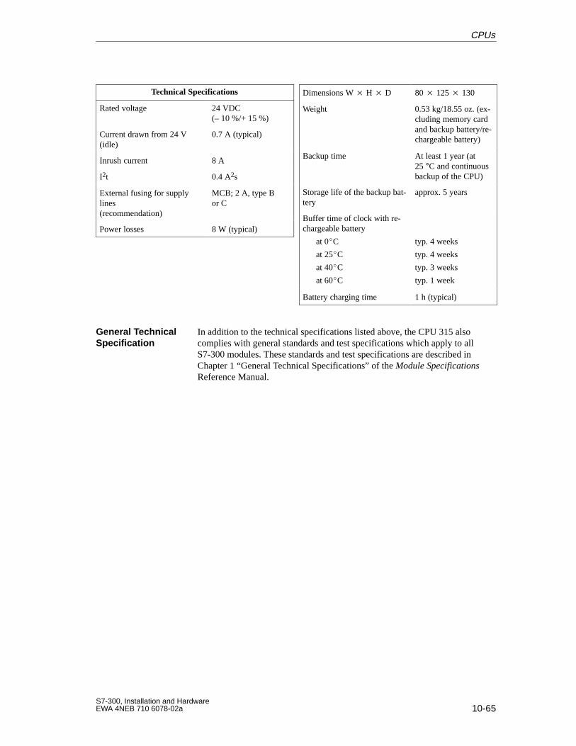
10-65S7-300, Installation and HardwareEWA 4NEB 710 6078-02a
Technical Specifications
Rated voltage 24 VDC(– 10 %/+ 15 %)
Current drawn from 24 V(idle)
0.7 A (typical)
Inrush current 8 A
I2t 0.4 A2s
External fusing for supplylines (recommendation)
MCB; 2 A, type Bor C
Power losses 8 W (typical)
Dimensions W H D 80 125 130
Weight 0.53 kg/18.55 oz. (ex-cluding memory cardand backup battery/re-chargeable battery)
Backup time At least 1 year (at 25 °C and continuousbackup of the CPU)
Storage life of the backup bat-tery
approx. 5 years
Buffer time of clock with re-chargeable battery
at 0C
at 25C
at 40C
at 60C
typ. 4 weeks
typ. 4 weeks
typ. 3 weeks
typ. 1 week
Battery charging time 1 h (typical)
In addition to the technical specifications listed above, the CPU 315 alsocomplies with general standards and test specifications which apply to allS7-300 modules. These standards and test specifications are described inChapter 1 “General Technical Specifications” of the Module SpecificationsReference Manual.
General TechnicalSpecification
CPUs
10-66S7-300, Installation and Hardware
EWA 4NEB 710 6078-02a
10.8.6 CPU 315-2 DP
6ES7 315-2AF02-0AB0
The CPU 315-2 DP has the following characteristic features:
DP master or DP slave
64 KB RAM
96 KB integral load memory (RAM);
expandable with memory card from 16 Kbytes to 512 Kbytes
Speed: approx. 0.3 ms per 1000 binary instructions
In the case of a combined central and distributed configuration, a total of1024 bytes of inputs and 1024 bytes of outputs can be connected that canbe addressed directly with load and transfer instructions up to addressbyte 1023. If consistent data areas are used, up to 2048 bytes of inputsand 2048 bytes of outputs can be used (see Section 3.2).
As a DP slave the CPU can be configured in STEP 7 from Version 3.1 orwith COM PROFIBUS from Version 3.1.
You can use the CPU 315-2 DP with its 2nd interface (PROFIBUS-DP inter-face) either as a DP master or as a DP slave in a PROFIBUS-DP network.
You can operate the CPU 315-2 DP as a DP master with up to 64 S7 DPslaves or other DP slaves (to standard EN 50170, Volume 2, PROFIBUS).
You can connect the CPU 315-2 DP as a DP slave to an S7 DP master or toanother DP master to standard EN 50170, Volume 2, PROFIBUS.
See Chapter 11 for a detailed description of the PROFIBUS-DP characteris-tics of the CPU 315-2 DP.
Order Number
Characteristic Features
DP Master or DPSlave
CPUs
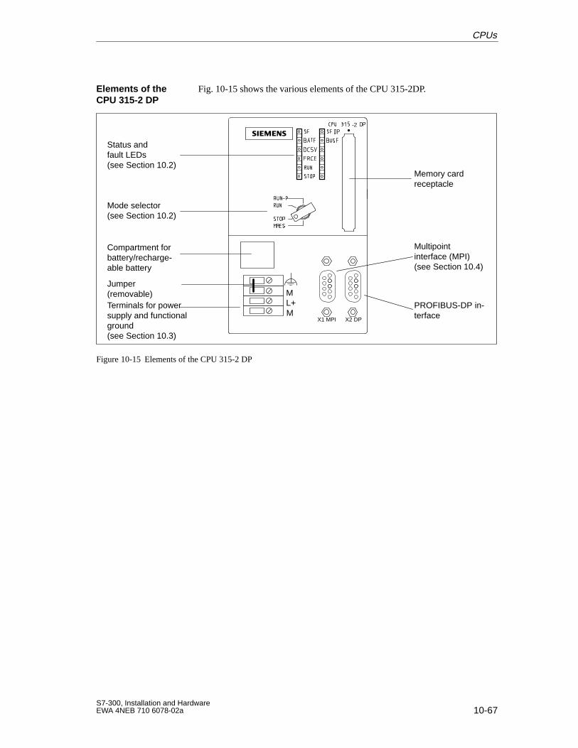
10-67S7-300, Installation and HardwareEWA 4NEB 710 6078-02a
Fig. 10-15 shows the various elements of the CPU 315-2DP.
Memory cardreceptacle
Compartment forbattery/recharge-able battery
ML+M
Jumper (removable)
X1 MPI X2 DP
PROFIBUS-DP in-terface
-2
Status andfault LEDs(see Section 10.2)
Mode selector(see Section 10.2)
Terminals for powersupply and functionalground(see Section 10.3)
Multipoint interface (MPI)(see Section 10.4)
Figure 10-15 Elements of the CPU 315-2 DP
Elements of theCPU 315-2 DP
CPUs
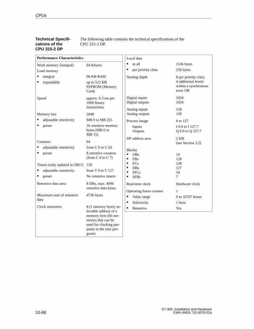
10-68S7-300, Installation and Hardware
EWA 4NEB 710 6078-02a
The following table contains the technical specifications of theCPU 315-2 DP.
Performance Characteristics
Work memory (integral)
Load memory
integral
expandable
64 Kbytes
96 KB RAM
up to 512 KBFEPROM (MemoryCard)
Speed approx. 0.3 ms per1000 binaryinstructions
Memory bits
adjustable retentivity
preset
2048
MB 0 to MB 255
16 retentive memorybytes (MB 0 toMB 15)
Counters
adjustable retentivity
preset
64
from C 0 to C 63
8 retentive counters(from C 0 to C 7)
Timers (only updated in OB1!)
adjustable retentivity
preset
128
from T 0 to T 127
No retentive timers
Retentive data area 8 DBs, max. 4096retentive data bytes
Maximum sum of retentivedata
4736 bytes
Clock memories 8 (1 memory byte); se-lectable address of amemory byte (bit me-mories that can beused for clocking pur-poses in the user pro-gram)
Local data
in all
per priority class
1536 bytes
256 bytes
Nesting depth 8 per priority class;4 additional levelswithin a synchronouserror OB
Digital inputsDigital outputs
10241024
Analog inputsAnalog outputs
128128
Process image
InputsOutputs
0 to 127
I 0.0 to I 127.7Q 0.0 to Q 127.7
DP address area 2 KB (see Section 3.2)
Blocks OBs FBs FCs DBs SFCs SFBs
14128128127547
Real-time clock Hardware clock
Operating hours counter
Value range
Selectivity
Retentive
1
0 to 32767 hours
1 hour
Yes
Technical Specifi -cations of theCPU 315-2 DP
CPUs
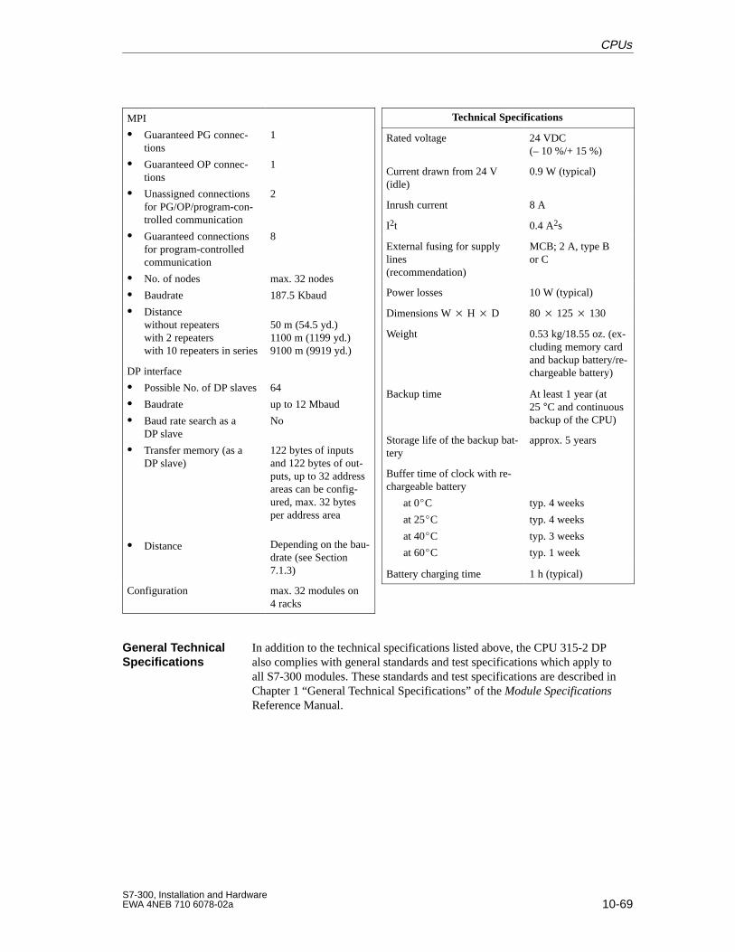
10-69S7-300, Installation and HardwareEWA 4NEB 710 6078-02a
MPI
Guaranteed PG connec-tions
Guaranteed OP connec-tions
Unassigned connectionsfor PG/OP/program-con-trolled communication
Guaranteed connectionsfor program-controlledcommunication
No. of nodes
Baudrate
Distancewithout repeaterswith 2 repeaterswith 10 repeaters in series
1
1
2
8
max. 32 nodes
187.5 Kbaud
50 m (54.5 yd.)1100 m (1199 yd.)9100 m (9919 yd.)
DP interface
Possible No. of DP slaves
Baudrate
Baud rate search as aDP slave
Transfer memory (as aDP slave)
Distance
64
up to 12 Mbaud
No
122 bytes of inputsand 122 bytes of out-puts, up to 32 addressareas can be config-ured, max. 32 bytesper address area
Depending on the bau-drate (see Section7.1.3)
Configuration max. 32 modules on4 racks
Technical Specifications
Rated voltage 24 VDC(– 10 %/+ 15 %)
Current drawn from 24 V(idle)
0.9 W (typical)
Inrush current 8 A
I2t 0.4 A2s
External fusing for supplylines (recommendation)
MCB; 2 A, type Bor C
Power losses 10 W (typical)
Dimensions W H D 80 125 130
Weight 0.53 kg/18.55 oz. (ex-cluding memory cardand backup battery/re-chargeable battery)
Backup time At least 1 year (at25 °C and continuousbackup of the CPU)
Storage life of the backup bat-tery
approx. 5 years
Buffer time of clock with re-chargeable battery
at 0C
at 25C
at 40C
at 60C
typ. 4 weeks
typ. 4 weeks
typ. 3 weeks
typ. 1 week
Battery charging time 1 h (typical)
In addition to the technical specifications listed above, the CPU 315-2 DPalso complies with general standards and test specifications which apply toall S7-300 modules. These standards and test specifications are described inChapter 1 “General Technical Specifications” of the Module SpecificationsReference Manual.
General TechnicalSpecifications
CPUs
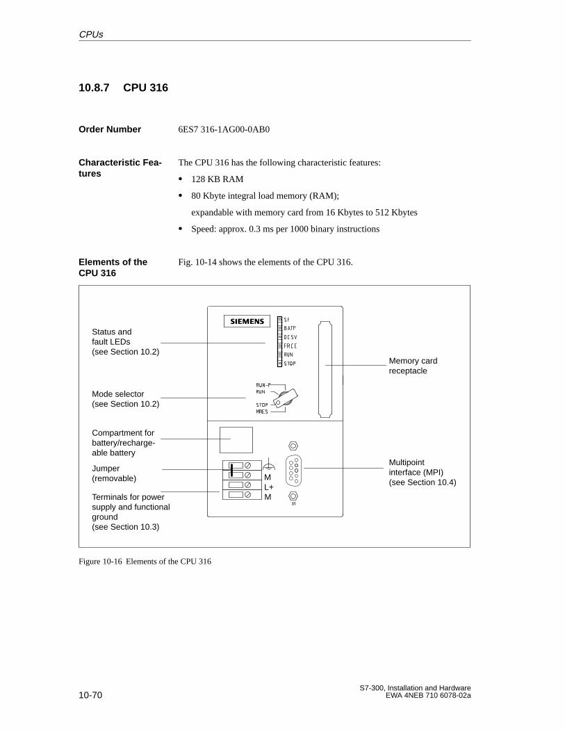
10-70S7-300, Installation and Hardware
EWA 4NEB 710 6078-02a
10.8.7 CPU 316
6ES7 316-1AG00-0AB0
The CPU 316 has the following characteristic features:
128 KB RAM
80 Kbyte integral load memory (RAM);
expandable with memory card from 16 Kbytes to 512 Kbytes
Speed: approx. 0.3 ms per 1000 binary instructions
Fig. 10-14 shows the elements of the CPU 316.
Memory cardreceptacle
Compartment forbattery/recharge-able battery
ML+M
Jumper (removable)
Status andfault LEDs(see Section 10.2)
Mode selector(see Section 10.2)
Terminals for powersupply and functionalground(see Section 10.3)
Multipoint interface (MPI)(see Section 10.4)
Figure 10-16 Elements of the CPU 316
Order Number
Characteristic Fea -tures
Elements of theCPU 316
CPUs
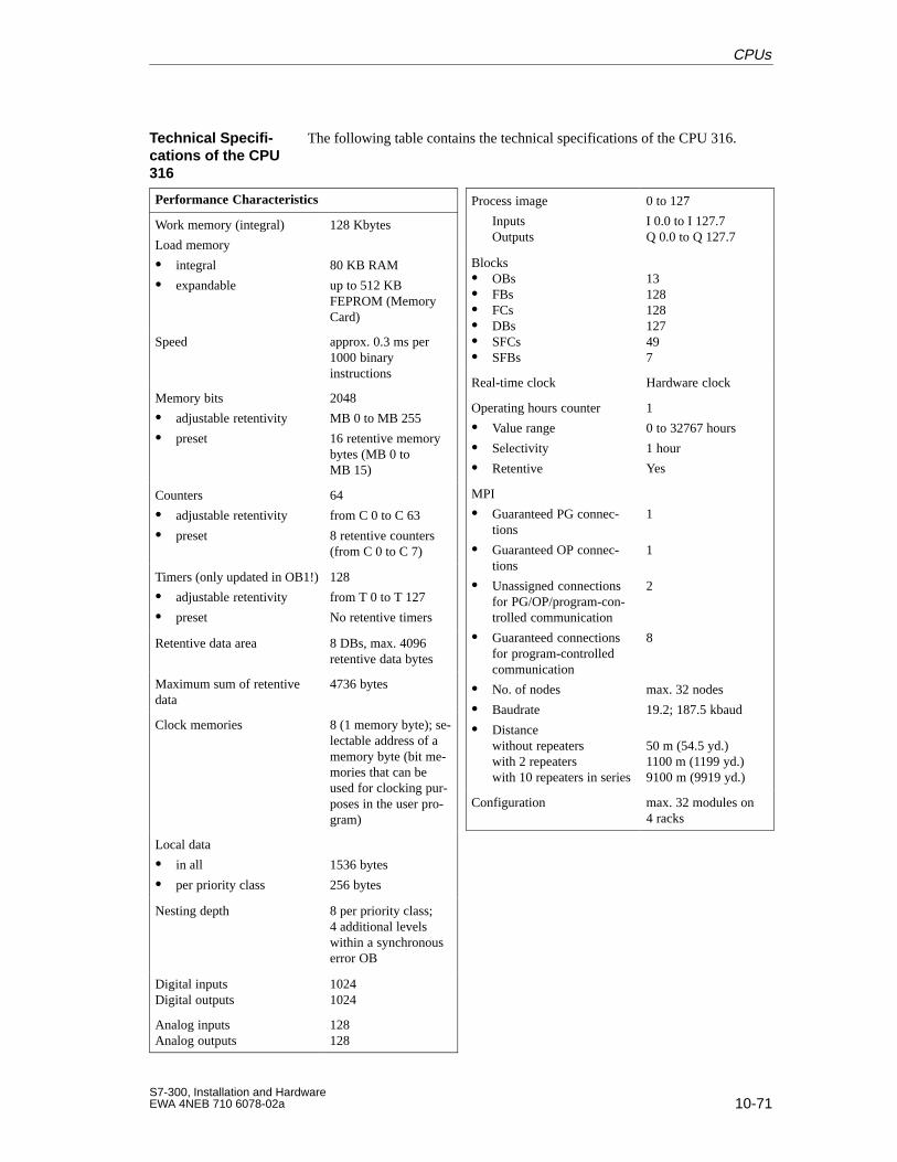
10-71S7-300, Installation and HardwareEWA 4NEB 710 6078-02a
The following table contains the technical specifications of the CPU 316.
Performance Characteristics
Work memory (integral)
Load memory
integral
expandable
128 Kbytes
80 KB RAM
up to 512 KBFEPROM (MemoryCard)
Speed approx. 0.3 ms per1000 binaryinstructions
Memory bits
adjustable retentivity
preset
2048
MB 0 to MB 255
16 retentive memorybytes (MB 0 toMB 15)
Counters
adjustable retentivity
preset
64
from C 0 to C 63
8 retentive counters(from C 0 to C 7)
Timers (only updated in OB1!)
adjustable retentivity
preset
128
from T 0 to T 127
No retentive timers
Retentive data area 8 DBs, max. 4096retentive data bytes
Maximum sum of retentivedata
4736 bytes
Clock memories 8 (1 memory byte); se-lectable address of amemory byte (bit me-mories that can beused for clocking pur-poses in the user pro-gram)
Local data
in all
per priority class
1536 bytes
256 bytes
Nesting depth 8 per priority class;4 additional levels within a synchronouserror OB
Digital inputsDigital outputs
10241024
Analog inputsAnalog outputs
128128
Process image
InputsOutputs
0 to 127
I 0.0 to I 127.7Q 0.0 to Q 127.7
Blocks OBs FBs FCs DBs SFCs SFBs
13128128127497
Real-time clock Hardware clock
Operating hours counter
Value range
Selectivity
Retentive
1
0 to 32767 hours
1 hour
Yes
MPI
Guaranteed PG connec-tions
Guaranteed OP connec-tions
Unassigned connectionsfor PG/OP/program-con-trolled communication
Guaranteed connectionsfor program-controlledcommunication
No. of nodes
Baudrate
Distancewithout repeaterswith 2 repeaterswith 10 repeaters in series
1
1
2
8
max. 32 nodes
19.2; 187.5 kbaud
50 m (54.5 yd.)1100 m (1199 yd.)9100 m (9919 yd.)
Configuration max. 32 modules on4 racks
Technical Specifi -cations of the CPU316
CPUs
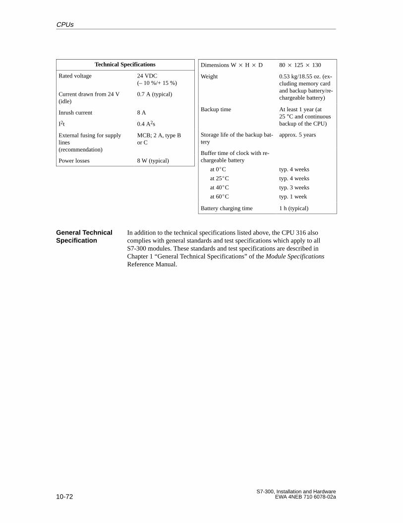
10-72S7-300, Installation and Hardware
EWA 4NEB 710 6078-02a
Technical Specifications
Rated voltage 24 VDC(– 10 %/+ 15 %)
Current drawn from 24 V(idle)
0.7 A (typical)
Inrush current 8 A
I2t 0.4 A2s
External fusing for supplylines (recommendation)
MCB; 2 A, type Bor C
Power losses 8 W (typical)
Dimensions W H D 80 125 130
Weight 0.53 kg/18.55 oz. (ex-cluding memory cardand backup battery/re-chargeable battery)
Backup time At least 1 year (at 25 °C and continuousbackup of the CPU)
Storage life of the backup bat-tery
approx. 5 years
Buffer time of clock with re-chargeable battery
at 0C
at 25C
at 40C
at 60C
typ. 4 weeks
typ. 4 weeks
typ. 3 weeks
typ. 1 week
Battery charging time 1 h (typical)
In addition to the technical specifications listed above, the CPU 316 alsocomplies with general standards and test specifications which apply to allS7-300 modules. These standards and test specifications are described inChapter 1 “General Technical Specifications” of the Module SpecificationsReference Manual.
General TechnicalSpecification
CPUs
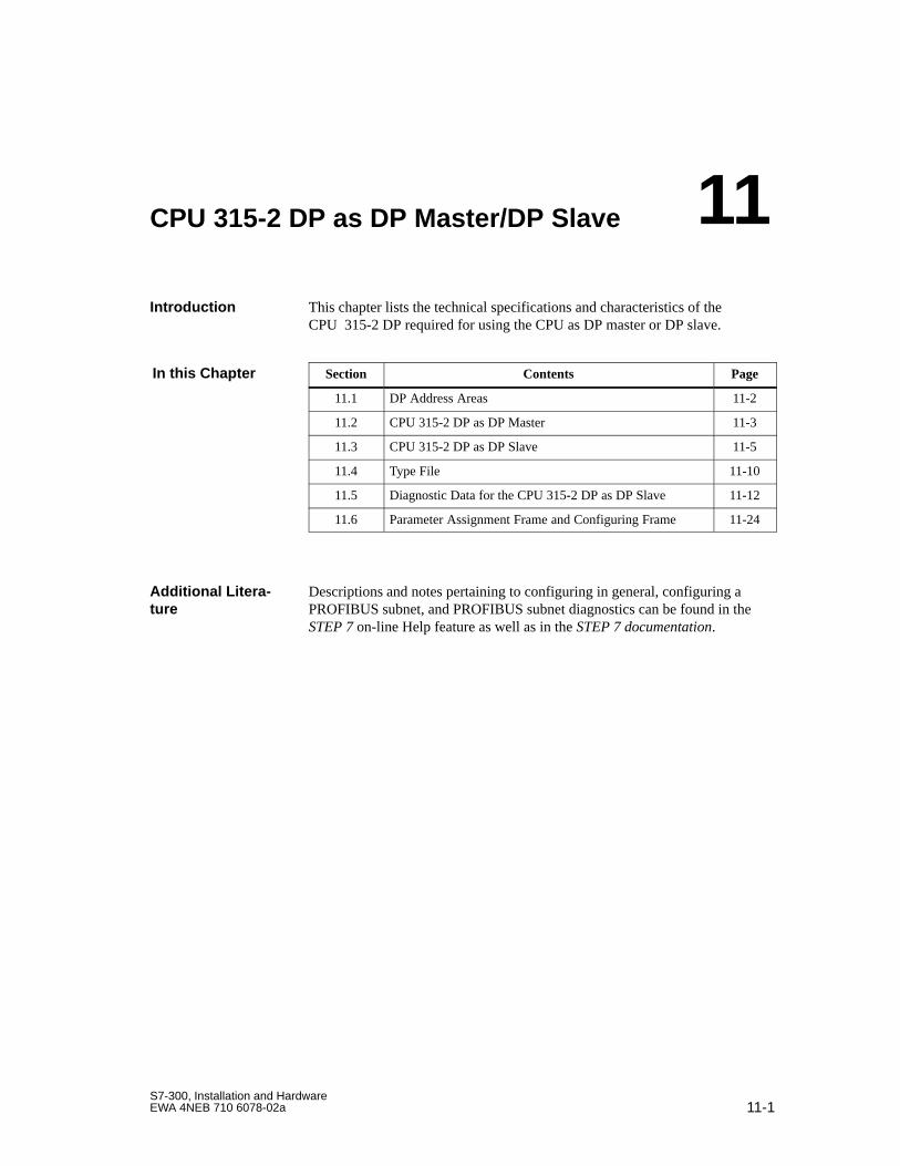
11-1S7-300, Installation and HardwareEWA 4NEB 710 6078-02a
CPU 315-2 DP as DP Master/DP Slave
This chapter lists the technical specifications and characteristics of theCPU 315-2 DP required for using the CPU as DP master or DP slave.
Section Contents Page
11.1 DP Address Areas 11-2
11.2 CPU 315-2 DP as DP Master 11-3
11.3 CPU 315-2 DP as DP Slave 11-5
11.4 Type File 11-10
11.5 Diagnostic Data for the CPU 315-2 DP as DP Slave 11-12
11.6 Parameter Assignment Frame and Configuring Frame 11-24
Descriptions and notes pertaining to configuring in general, configuring aPROFIBUS subnet, and PROFIBUS subnet diagnostics can be found in theSTEP 7 on-line Help feature as well as in the STEP 7 documentation.
Introduction
In this Chapter
Additional Litera-ture
11
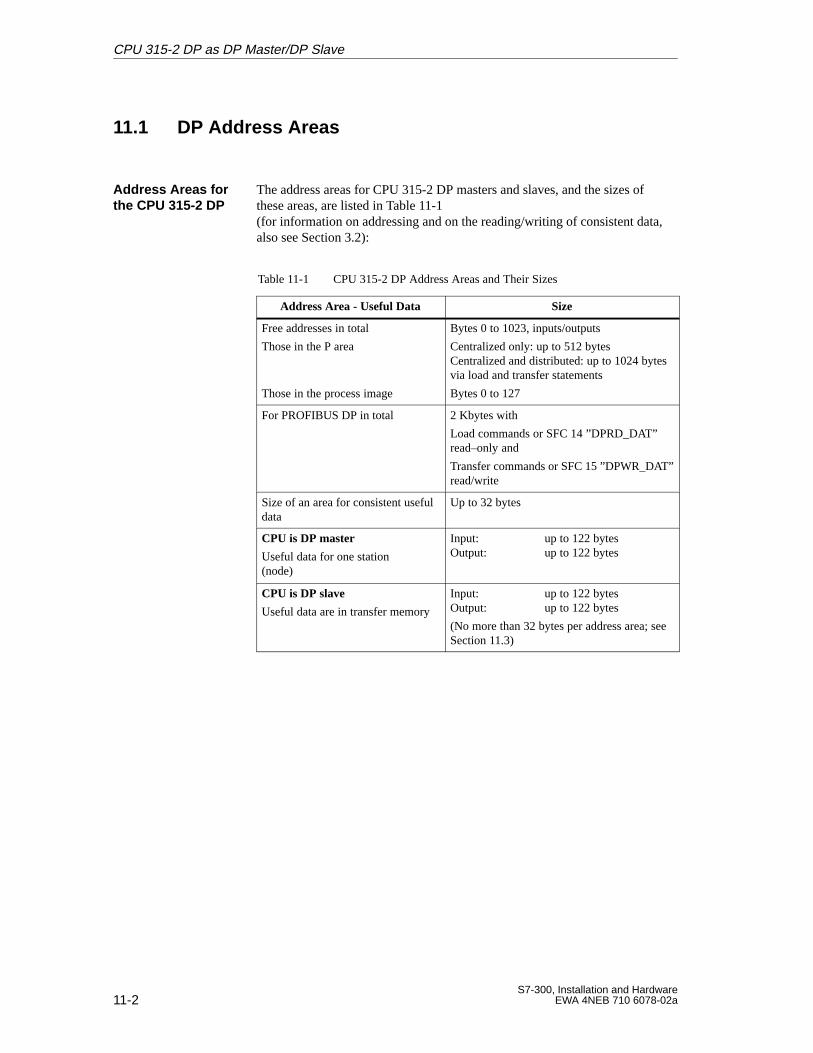
11-2S7-300, Installation and Hardware
EWA 4NEB 710 6078-02a
11.1 DP Address Areas
The address areas for CPU 315-2 DP masters and slaves, and the sizes ofthese areas, are listed in Table 11-1 (for information on addressing and on the reading/writing of consistent data,also see Section 3.2):
Table 11-1 CPU 315-2 DP Address Areas and Their Sizes
Address Area - Useful Data Size
Free addresses in total
Those in the P area
Those in the process image
Bytes 0 to 1023, inputs/outputs
Centralized only: up to 512 bytesCentralized and distributed: up to 1024 bytesvia load and transfer statements
Bytes 0 to 127
For PROFIBUS DP in total 2 Kbytes with
Load commands or SFC 14 ”DPRD_DAT”read–only and
Transfer commands or SFC 15 ”DPWR_DAT”read/write
Size of an area for consistent usefuldata
Up to 32 bytes
CPU is DP master
Useful data for one station (node)
Input: up to 122 bytesOutput: up to 122 bytes
CPU is DP slave
Useful data are in transfer memory
Input: up to 122 bytesOutput: up to 122 bytes
(No more than 32 bytes per address area; seeSection 11.3)
Address Areas forthe CPU 315-2 DP
CPU 315-2 DP as DP Master/DP Slave
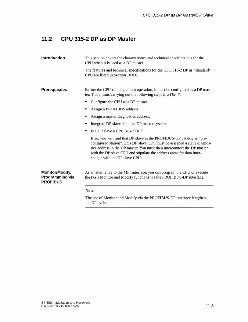
11-3S7-300, Installation and HardwareEWA 4NEB 710 6078-02a
11.2 CPU 315-2 DP as DP Master
This section covers the characteristics and technical specifications for theCPU when it is used as a DP master.
The features and technical specifications for the CPU 315-2 DP as “standard”CPU are listed in Section 10.8.6.
Before the CPU can be put into operation, it must be configured as a DP mas-ter. This means carrying out the following steps in STEP 7:
Configure the CPU as a DP master.
Assign a PROFIBUS address.
Assign a master diagnostics address.
Integrate DP slaves into the DP master system.
Is a DP slave a CPU 315-2 DP?
If so, you will find that DP slave in the PROFIBUS-DP catalog as “pre-configured station”. This DP slave CPU must be assigned a slave diagnos-tics address in the DP master. You must then interconnect the DP masterwith the DP slave CPU and stipulate the address areas for data inter-change with the DP slave CPU.
As an alternative to the MPI interface, you can program the CPU or executethe PG’s Monitor and Modify functions via the PROFIBUS-DP interface.
Note
The use of Monitor and Modify via the PROFIBUS-DP interface lengthensthe DP cycle.
Introduction
Prerequisites
Monitor/Modify, Programming viaPROFIBUS
CPU 315-2 DP as DP Master/DP Slave
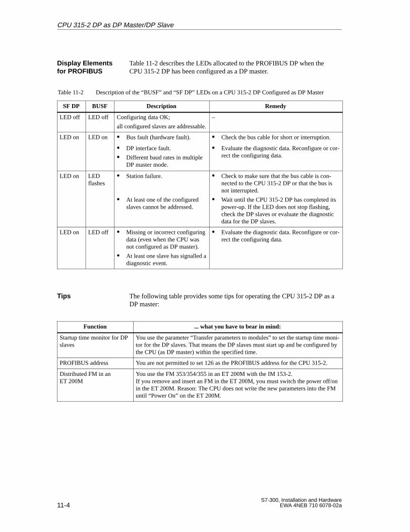
11-4S7-300, Installation and Hardware
EWA 4NEB 710 6078-02a
Table 11-2 describes the LEDs allocated to the PROFIBUS DP when theCPU 315-2 DP has been configured as a DP master.
Table 11-2 Description of the “BUSF” and “SF DP” LEDs on a CPU 315-2 DP Configured as DP Master
SF DP BUSF Description Remedy
LED off LED off Configuring data OK;
all configured slaves are addressable.
–
LED on LED on Bus fault (hardware fault). Check the bus cable for short or interruption.
DP interface fault.
Different baud rates in multipleDP master mode.
Evaluate the diagnostic data. Reconfigure or cor-rect the configuring data.
LED on LEDflashes
Station failure.
At least one of the configuredslaves cannot be addressed.
Check to make sure that the bus cable is con-nected to the CPU 315-2 DP or that the bus isnot interrupted.
Wait until the CPU 315-2 DP has completed itspower-up. If the LED does not stop flashing,check the DP slaves or evaluate the diagnosticdata for the DP slaves.
LED on LED off Missing or incorrect configuringdata (even when the CPU wasnot configured as DP master).
At least one slave has signalled adiagnostic event.
Evaluate the diagnostic data. Reconfigure or cor-rect the configuring data.
The following table provides some tips for operating the CPU 315-2 DP as aDP master:
Function ... what you have to bear in mind:
Startup time monitor for DPslaves
You use the parameter “Transfer parameters to modules” to set the startup time moni-tor for the DP slaves. That means the DP slaves must start up and be configured bythe CPU (as DP master) within the specified time.
PROFIBUS address You are not permitted to set 126 as the PROFIBUS address for the CPU 315-2.
Distributed FM in anET 200M
You use the FM 353/354/355 in an ET 200M with the IM 153-2.If you remove and insert an FM in the ET 200M, you must switch the power off/onin the ET 200M. Reason: The CPU does not write the new parameters into the FMuntil “Power On” on the ET 200M.
Display Elementsfor PROFIBUS
Tips
CPU 315-2 DP as DP Master/DP Slave
11-5S7-300, Installation and HardwareEWA 4NEB 710 6078-02a
11.3 CPU 315-2 DP as a DP Slave
This section lists the characteristics and technical specifications for the CPUwhen it is operated as a DP slave.
The characteristics and technical specifications for the CPU as “standard”CPU can be found in Section 10.8.6.
Prior to start-up, the CPU must be configured as a DP slave. This means car-rying out the following steps in STEP 7:
“Switch on” the CPU as DP slave.
Assign a PROFIBUS address.
Assign a slave diagnostics address.
Stipulate the address areas for data interchange with the DP master.
As an alternative to the MPI interface, you can program the CPU or executethe PG’s Monitor and Modify functions via the PROFIBUS-DP interface. Todo so, you must enable these functions when configuring the CPU as DPslave in STEP 7.
Note
The use of Monitor and Modify via the PROFIBUS-DP interface lengthensthe DP cycle.
Introduction
Prerequisites
Monitor/Modify, Programming viaPROFIBUS
CPU 315-2 DP as DP Master/DP Slave
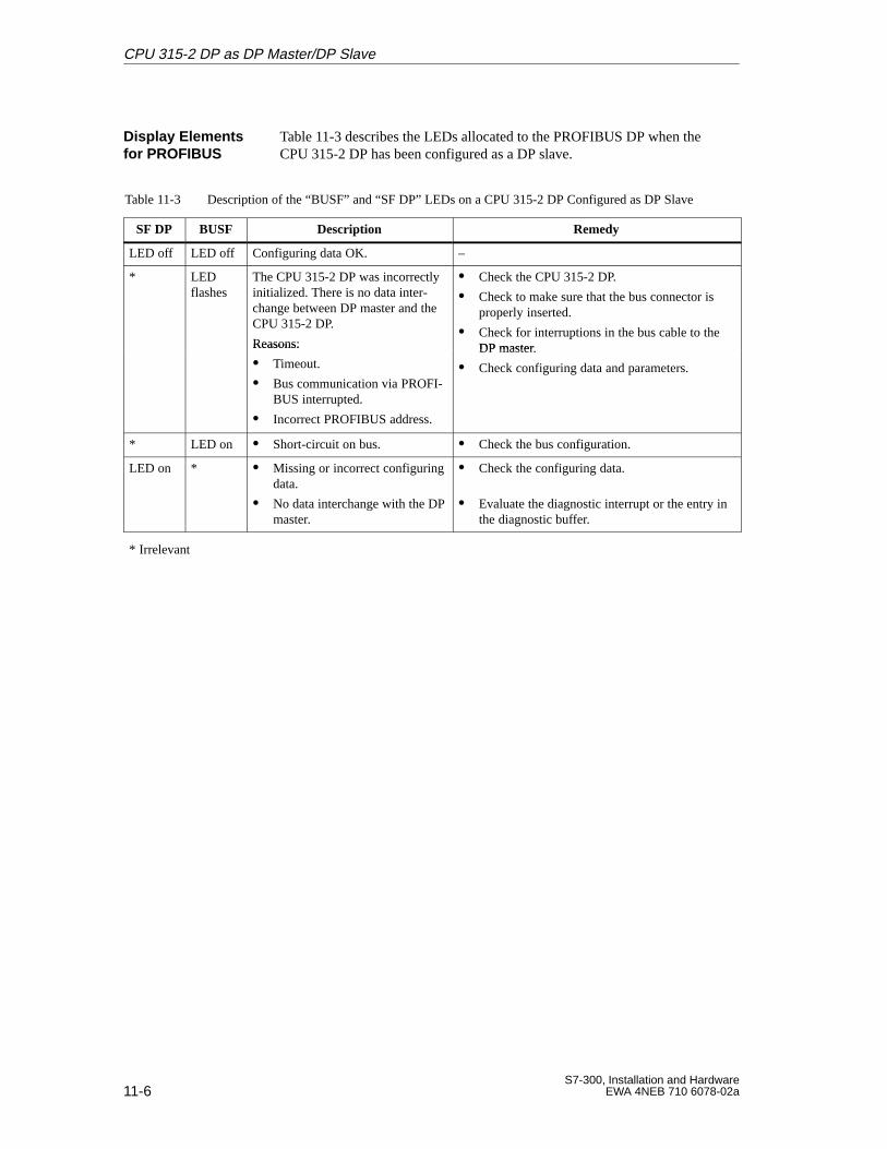
11-6S7-300, Installation and Hardware
EWA 4NEB 710 6078-02a
Table 11-3 describes the LEDs allocated to the PROFIBUS DP when theCPU 315-2 DP has been configured as a DP slave.
Table 11-3 Description of the “BUSF” and “SF DP” LEDs on a CPU 315-2 DP Configured as DP Slave
SF DP BUSF Description Remedy
LED off LED off Configuring data OK. –
* LEDflashes
The CPU 315-2 DP was incorrectlyinitialized. There is no data inter-change between DP master and theCPU 315-2 DP.
Reasons:
Check the CPU 315-2 DP.
Check to make sure that the bus connector isproperly inserted.
Check for interruptions in the bus cable to theDP masterReasons:
Timeout.
Bus communication via PROFI-BUS interrupted.
Incorrect PROFIBUS address.
DP master.
Check configuring data and parameters.
* LED on Short-circuit on bus. Check the bus configuration.
LED on * Missing or incorrect configuringdata.
No data interchange with the DPmaster.
Check the configuring data.
Evaluate the diagnostic interrupt or the entry inthe diagnostic buffer.
* Irrelevant
Display Elementsfor PROFIBUS
CPU 315-2 DP as DP Master/DP Slave
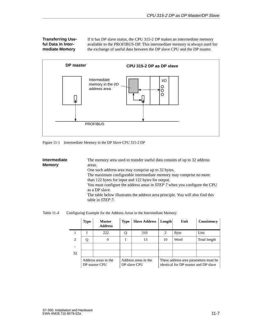
11-7S7-300, Installation and HardwareEWA 4NEB 710 6078-02a
If it has DP slave status, the CPU 315-2 DP makes an intermediate memoryavailable to the PROFIBUS-DP. This intermediate memory is always used forthe exchange of useful data between the DP slave CPU and the DP master.
Intermediate memory in the I/Oaddress area
PROFIBUS
I/O
CPU 315-2 DP as DP slaveDP master
Figure 11-1 Intermediate Memory in the DP Slave CPU 315-2 DP
The memory area used to transfer useful data consists of up to 32 addressareas. One such address area may comprise up to 32 bytes. The maximum configurable intermediate memory may comprise no morethan 122 bytes for input and 122 bytes for output. You must configure the address areas in STEP 7 when you configure the CPUas a DP slave. The table below illustrates the address area principle. You will also find thistable in STEP 7.
Table 11-4 Configuring Example for the Address Areas in the Intermediate Memory
Type Master Address
Type Slave Address Length Unit Consistency
1 I 222 Q 310 2 Byte Unit
2 Q 0 I 13 10 Word Total length
:
32
Address areas in theDP master CPU
Address areas in theDP slave CPU
These address area parameters must beidentical for DP master and DP slave
Transferring Use-ful Data in Inter-mediate Memory
IntermediateMemory
CPU 315-2 DP as DP Master/DP Slave
11-8S7-300, Installation and Hardware
EWA 4NEB 710 6078-02a
The following rules must be followed when using the intermediate memory:
Allocating the address areas:
– Input data of the DP slave are always output data of the DP master
– Output data of the DP slave are always input data of the DP master
The addresses can be freely allocated. In the user program, access thedata with Load/Transfer statements or with SFCs 14 and 15. You may alsospecify addresses from the process input or process output image (also seeSection 3.2).
Note
Assign addresses from the CPU 315-2 DP’s DP address area to the inter-mediate memory.
Never allocate the addresses already assigned to the intermediate memory toI/O modules connected to the CPU 315-2 DP!
The lowest address in any given address area is that address area’s startaddress.
The length, unit and consistency of the address areas for DP master andDP slave must be identical.
The following applies to the interchange of consistent data when using an IM308 C as DP master and a CPU 315-2 DP as DP slave:
In the IM 308 C, you must program FB 192 to enable the exchange of consis-tent data between DP master and DP slave. With FB 192, CPU 315-2 DP dataare output or read out consecutively in one block!
Rules
S5 DP Master
CPU 315-2 DP as DP Master/DP Slave
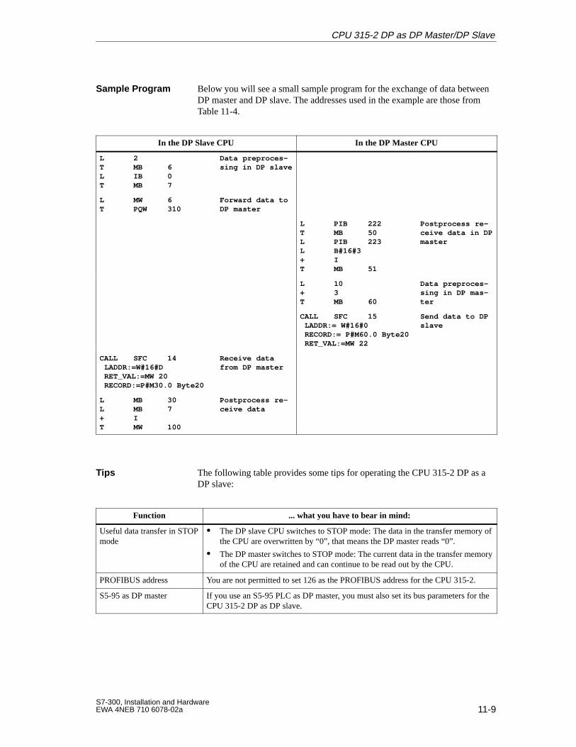
11-9S7-300, Installation and HardwareEWA 4NEB 710 6078-02a
Below you will see a small sample program for the exchange of data betweenDP master and DP slave. The addresses used in the example are those fromTable 11-4.
In the DP Slave CPU In the DP Master CPU
L 2T MB 6L IB 0T MB 7
Data preproces-sing in DP slave
L MW 6T PQW 310
Forward data toDP master
L PIB 222T MB 50L PIB 223L B#16#3+ IT MB 51
Postprocess re-ceive data in DPmaster
L 10+ 3T MB 60
Data preproces-sing in DP mas-ter
CALL SFC 15 LADDR:= W#16#0 RECORD:= P#M60.0 Byte20 RET_VAL:=MW 22
Send data to DPslave
CALL SFC 14 LADDR:=W#16#D RET_VAL:=MW 20 RECORD:=P#M30.0 Byte20
Receive datafrom DP master
L MB 30L MB 7+ IT MW 100
Postprocess re-ceive data
The following table provides some tips for operating the CPU 315-2 DP as aDP slave:
Function ... what you have to bear in mind:
Useful data transfer in STOPmode
The DP slave CPU switches to STOP mode: The data in the transfer memory ofthe CPU are overwritten by “0”, that means the DP master reads “0”.
The DP master switches to STOP mode: The current data in the transfer memoryof the CPU are retained and can continue to be read out by the CPU.
PROFIBUS address You are not permitted to set 126 as the PROFIBUS address for the CPU 315-2.
S5-95 as DP master If you use an S5-95 PLC as DP master, you must also set its bus parameters for theCPU 315-2 DP as DP slave.
Sample Program
Tips
CPU 315-2 DP as DP Master/DP Slave
11-10S7-300, Installation and Hardware
EWA 4NEB 710 6078-02a
11.4 Type File
The type file is included in COM PROFIBUS beginning Version 3.1.
If you do not have a type file, you can call it up via modem from the Inter-face Center Fuerth by calling +49/911/737972.
A type file contains all characteristics of a DP slave.
You require a GSD file only when using an S7-300 equipped with a CPU315-2 DP as slave together with a DP master which cannot process the typefile.
The GSD file can be obtained via modem from the Interface Center Fuerthby calling +49/911/737972.
All slave-specific characteristics are stored on a device master file (GSDfile). The format of the GSD file is defined in the EN 50170 standard, Vol-ume 2, PROFIBUS.
If your DP master does not support the identification format described in thismanual (see Section 11.6.2), you can obtain another type/GSD file by callingthe Interface Center Fuerth.
Type Files
Definition of aType File
GSD Files
Definition of aGSD File
Other Type/GSDFiles
CPU 315-2 DP as DP Master/DP Slave
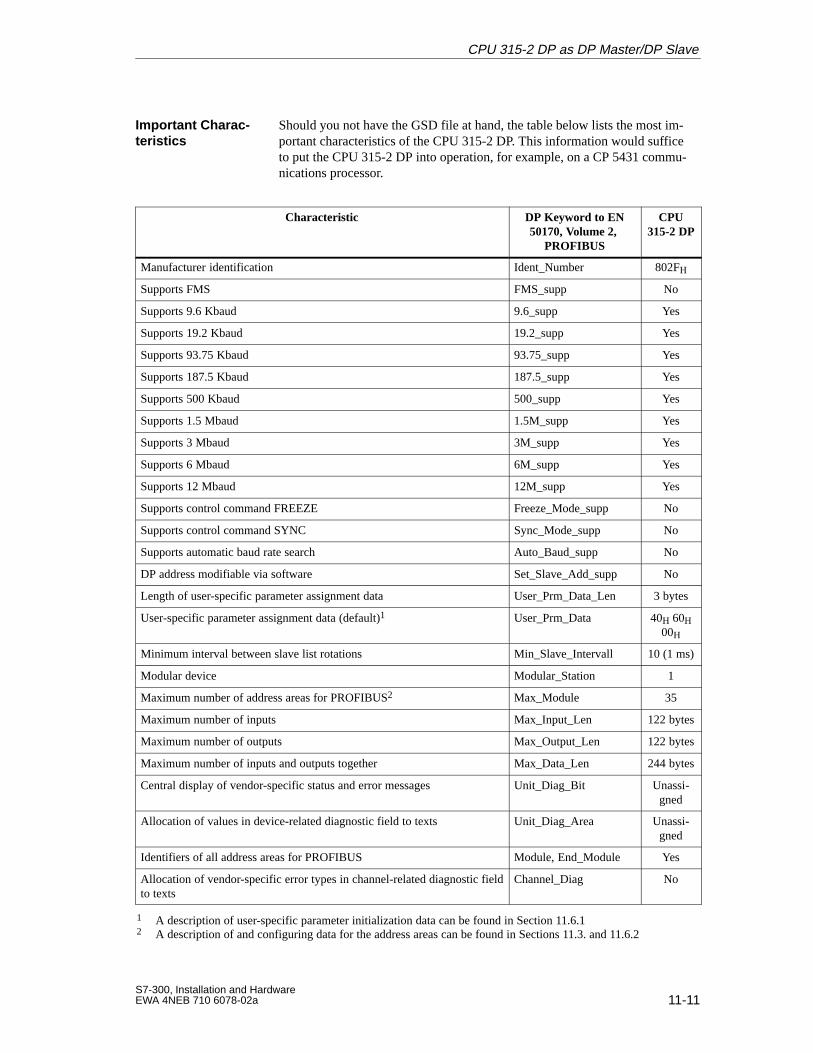
11-11S7-300, Installation and HardwareEWA 4NEB 710 6078-02a
Should you not have the GSD file at hand, the table below lists the most im-portant characteristics of the CPU 315-2 DP. This information would sufficeto put the CPU 315-2 DP into operation, for example, on a CP 5431 commu-nications processor.
Characteristic DP Keyword to EN50170, Volume 2,
PROFIBUS
CPU315-2 DP
Manufacturer identification Ident_Number 802FH
Supports FMS FMS_supp No
Supports 9.6 Kbaud 9.6_supp Yes
Supports 19.2 Kbaud 19.2_supp Yes
Supports 93.75 Kbaud 93.75_supp Yes
Supports 187.5 Kbaud 187.5_supp Yes
Supports 500 Kbaud 500_supp Yes
Supports 1.5 Mbaud 1.5M_supp Yes
Supports 3 Mbaud 3M_supp Yes
Supports 6 Mbaud 6M_supp Yes
Supports 12 Mbaud 12M_supp Yes
Supports control command FREEZE Freeze_Mode_supp No
Supports control command SYNC Sync_Mode_supp No
Supports automatic baud rate search Auto_Baud_supp No
DP address modifiable via software Set_Slave_Add_supp No
Length of user-specific parameter assignment data User_Prm_Data_Len 3 bytes
User-specific parameter assignment data (default)1 User_Prm_Data 40H 60H00H
Minimum interval between slave list rotations Min_Slave_Intervall 10 (1 ms)
Modular device Modular_Station 1
Maximum number of address areas for PROFIBUS2 Max_Module 35
Maximum number of inputs Max_Input_Len 122 bytes
Maximum number of outputs Max_Output_Len 122 bytes
Maximum number of inputs and outputs together Max_Data_Len 244 bytes
Central display of vendor-specific status and error messages Unit_Diag_Bit Unassi-gned
Allocation of values in device-related diagnostic field to texts Unit_Diag_Area Unassi-gned
Identifiers of all address areas for PROFIBUS Module, End_Module Yes
Allocation of vendor-specific error types in channel-related diagnostic fieldto texts
Channel_Diag No
1 A description of user-specific parameter initialization data can be found in Section 11.6.12 A description of and configuring data for the address areas can be found in Sections 11.3. and 11.6.2
Important Charac -teristics
CPU 315-2 DP as DP Master/DP Slave
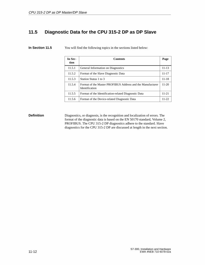
11-12S7-300, Installation and Hardware
EWA 4NEB 710 6078-02a
11.5 Diagnostic Data for the CPU 315-2 DP as DP Slave
You will find the following topics in the sections listed below:
In Sec-tion
Contents Page
11.5.1 General Information on Diagnostics 11-13
11.5.2 Format of the Slave Diagnostic Data 11-17
11.5.3 Station Status 1 to 3 11-18
11.5.4 Format of the Master PROFIBUS Address and the ManufacturerIdentification
11-20
11.5.5 Format of the Identification-related Diagnostic Data 11-21
11.5.6 Format of the Device-related Diagnostic Data 11-22
Diagnostics, or diagnosis, is the recognition and localization of errors. Theformat of the diagnostic data is based on the EN 50170 standard, Volume 2,PROFIBUS. The CPU 315-2 DP diagnostics adhere to the standard. Slavediagnostics for the CPU 315-2 DP are discussed at length in the next section.
In Section 1 1.5
Definition
CPU 315-2 DP as DP Master/DP Slave
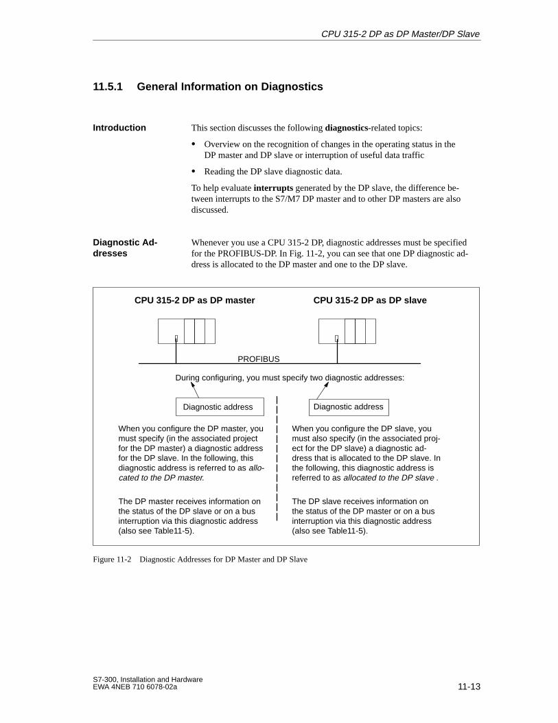
11-13S7-300, Installation and HardwareEWA 4NEB 710 6078-02a
11.5.1 General Information on Diagnostics
This section discusses the following diagnostics-related topics:
Overview on the recognition of changes in the operating status in theDP master and DP slave or interruption of useful data traffic
Reading the DP slave diagnostic data.
To help evaluate interrupts generated by the DP slave, the difference be-tween interrupts to the S7/M7 DP master and to other DP masters are alsodiscussed.
Whenever you use a CPU 315-2 DP, diagnostic addresses must be specifiedfor the PROFIBUS-DP. In Fig. 11-2, you can see that one DP diagnostic ad-dress is allocated to the DP master and one to the DP slave.
During configuring, you must specify two diagnostic addresses:
PROFIBUS
CPU 315-2 DP as DP slaveCPU 315-2 DP as DP master
Diagnostic address Diagnostic address
When you configure the DP master, youmust specify (in the associated projectfor the DP master) a diagnostic addressfor the DP slave. In the following, thisdiagnostic address is referred to as allo-cated to the DP master.
When you configure the DP slave, youmust also specify (in the associated proj-ect for the DP slave) a diagnostic ad-dress that is allocated to the DP slave. Inthe following, this diagnostic address isreferred to as allocated to the DP slave .
The DP master receives information onthe status of the DP slave or on a businterruption via this diagnostic address(also see Table11-5).
The DP slave receives information onthe status of the DP master or on a businterruption via this diagnostic address(also see Table11-5).
Figure 11-2 Diagnostic Addresses for DP Master and DP Slave
Introduction
Diagnostic Ad-dresses
CPU 315-2 DP as DP Master/DP Slave
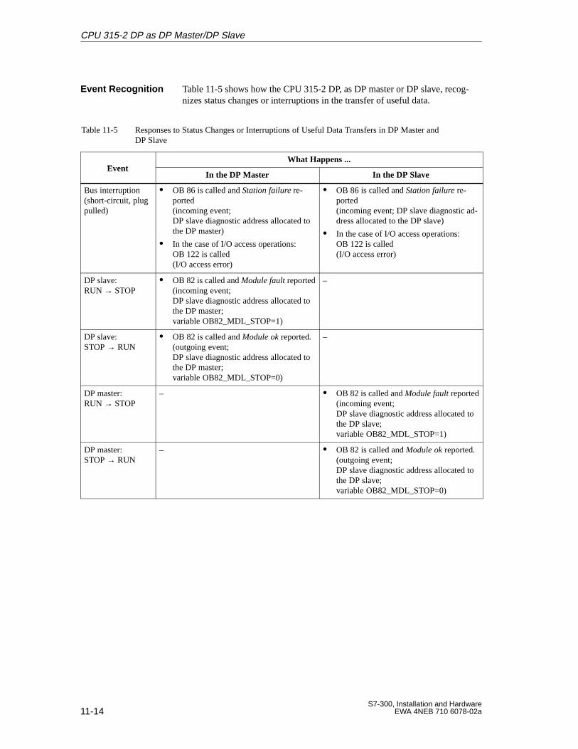
11-14S7-300, Installation and Hardware
EWA 4NEB 710 6078-02a
Table 11-5 shows how the CPU 315-2 DP, as DP master or DP slave, recog-nizes status changes or interruptions in the transfer of useful data.
Table 11-5 Responses to Status Changes or Interruptions of Useful Data Transfers in DP Master andDP Slave
EventWhat Happens ...
EventIn the DP Master In the DP Slave
Bus interruption(short-circuit, plugpulled)
OB 86 is called and Station failure re-ported(incoming event;DP slave diagnostic address allocated tothe DP master)
In the case of I/O access operations:OB 122 is called (I/O access error)
OB 86 is called and Station failure re-ported (incoming event; DP slave diagnostic ad-dress allocated to the DP slave)
In the case of I/O access operations:OB 122 is called (I/O access error)
DP slave: RUN → STOP
OB 82 is called and Module fault reported(incoming event;DP slave diagnostic address allocated tothe DP master;variable OB82_MDL_STOP=1)
–
DP slave: STOP → RUN
OB 82 is called and Module ok reported.(outgoing event;DP slave diagnostic address allocated tothe DP master; variable OB82_MDL_STOP=0)
–
DP master: RUN → STOP
– OB 82 is called and Module fault reported(incoming event; DP slave diagnostic address allocated tothe DP slave;variable OB82_MDL_STOP=1)
DP master: STOP → RUN
– OB 82 is called and Module ok reported. (outgoing event; DP slave diagnostic address allocated tothe DP slave;variable OB82_MDL_STOP=0)
Event Recognition
CPU 315-2 DP as DP Master/DP Slave
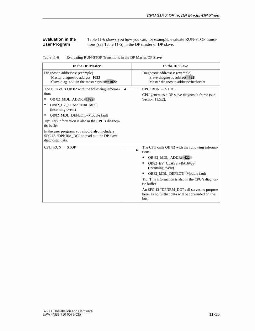
11-15S7-300, Installation and HardwareEWA 4NEB 710 6078-02a
Table 11-6 shows you how you can, for example, evaluate RUN-STOP transi-tions (see Table 11-5) in the DP master or DP slave.
Table 11-6 Evaluating RUN-STOP Transitions in the DP Master/DP Slave
In the DP Master In the DP Slave
Diagnostic addresses: (example)Master diagnostic address=1023Slave diag. add. in the master system=1022
Diagnostic addresses: (example)Slave diagnostic address=422Master diagnostic address=Irrelevant
The CPU calls OB 82 with the following informa-tion:
OB 82_MDL_ADDR:=1022
OB82_EV_CLASS:=B#16#39(incoming event)
OB82_MDL_DEFECT:=Module fault
Tip: This information is also in the CPU’s diagnos-tic buffer
In the user program, you should also include aSFC 13 “DPNRM_DG” to read out the DP slavediagnostic data.
CPU: RUN → STOP
CPU generates a DP slave diagnostic frame (seeSection 11.5.2).
CPU: RUN → STOP The CPU calls OB 82 with the following informa-tion:
OB 82_MDL_ADDR:=422
OB82_EV_CLASS:=B#16#39(incoming event)
OB82_MDL_DEFECT:=Module fault
Tip: This information is also in the CPU’s diagnos-tic buffer
An SFC 13 “DPNRM_DG” call serves no purposehere, as no further data will be forwarded on thebus!
Evaluation in theUser Program
CPU 315-2 DP as DP Master/DP Slave
11-16S7-300, Installation and Hardware
EWA 4NEB 710 6078-02a
In an S7 DP master, the DP slave diagnostic data are read out withSFC 13 “DPNRM_DG”. The format of the DP slave diagnostic data can befound in Sections 11.5.2 to 11.5.6.
For configurations in which the CPU 315-2 DP is used as a DP slave withanother DP master (such as an IM 308-C in SIMATIC S5), you can find theformat of the slave diagnostic data for the CPU 315-2 DP in Sections 11.5.2to 11.5.6.
You can generate a process interrupt in the DP master via the CPU 315-2 DPslave’s user program. OB 40 is called in the DP master’s user program bycalling SFC 7 “DP_PRAL”. SFC 7 allows you to to forward interrupt infor-mation in a doubleword to the DP master; this information can then be evalu-ated in OB 40 in variable OB40_POINT_ADDR. A detailed description ofSFC 7 “DP_PRAL” can be found in the reference manual entitled SystemSoftware S7-300/400 - System and Standard Functions.
If you operate the CPU 315-2 DP with another DP master, these interrupts aresimulated in the CPU 315-2 DP’s device-related diagnostics. You must post-process the relevant diagnostic events in the DP master’s user program.
Note
Note the following in order to be able to evaluate diagnostic interrupts andprocess interrupts via the device-related diagnostics when using a differentDP master:
The DP master should be able to store the diagnostic messages, that is,the DP master should have a ring buffer in which to place these mes-sages. If the DP master can not store diagnostic messages, only the lastdiagnostic message would be available for evaluation.
You must scan the relevant bits in the device-related diagnostic data inyour user program at regular intervals. You must also take the PROFI-BUS-DP’s bus cycle time into consideration so that you can scan the bitsat least once in sync with the bus cycle time, for example.
When using an IM 308-C as DP master, you can not utilize process inter-rupts in device-related diagnostics, as only incoming interrupts can besignalled, not outgoing interrupts.
Diagnostics withan S7 DP Master
Diagnostics with aDifferent DP Mas -ter
Interrupts with anS7/M7 DP Master
Interrupts with aDifferent DP Mas -ter
CPU 315-2 DP as DP Master/DP Slave
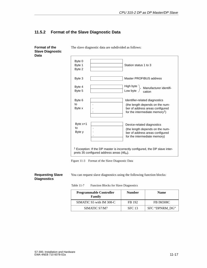
11-17S7-300, Installation and HardwareEWA 4NEB 710 6078-02a
11.5.2 Format of the Slave Diagnostic Data
The slave diagnostic data are subdivided as follows:
Byte 0Byte 1 Station status 1 to 3Byte 2
Byte 3 Master PROFIBUS address
Byte 4Byte 5 Low byte
High byteManufacturer identifi-cation
Byte 6to
Identifier-related diagnostics
Byte x
Device-related diagnostics...
.
.
.
Byte x+1toByte y
(the length depends on the num-ber of address areas configuredfor the intermediate memory1)
(the length depends on the num-ber of address areas configuredfor the intermediate memory)
1 Exception: If the DP master is incorrectly configured, the DP slave inter-prets 35 configured address areas (46H).
Figure 11-3 Format of the Slave Diagnostic Data
You can request slave diagnostics using the following function blocks:
Table 11-7 Function Blocks for Slave Diagnostics
Programmable Controller Family
Number Name
SIMATIC S5 with IM 308-C FB 192 FB IM308C
SIMATIC S7/M7 SFC 13 SFC “DPNRM_DG”
Format of theSlave DiagnosticData
Requesting SlaveDiagnostics
CPU 315-2 DP as DP Master/DP Slave
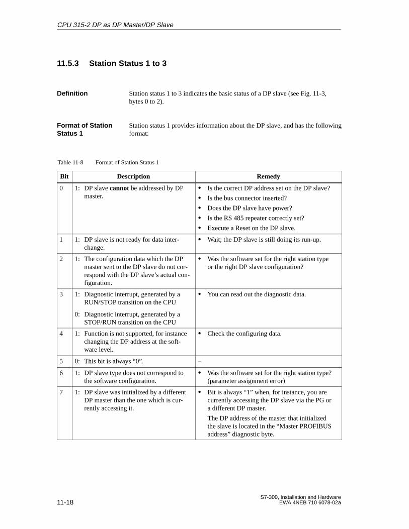
11-18S7-300, Installation and Hardware
EWA 4NEB 710 6078-02a
11.5.3 Station Status 1 to 3
Station status 1 to 3 indicates the basic status of a DP slave (see Fig. 11-3,bytes 0 to 2).
Station status 1 provides information about the DP slave, and has the followingformat:
Table 11-8 Format of Station Status 1
Bit Description Remedy
0 1: DP slave cannot be addressed by DPmaster.
Is the correct DP address set on the DP slave?
Is the bus connector inserted?
Does the DP slave have power?
Is the RS 485 repeater correctly set?
Execute a Reset on the DP slave.
1 1: DP slave is not ready for data inter-change.
Wait; the DP slave is still doing its run-up.
2 1: The configuration data which the DPmaster sent to the DP slave do not cor-respond with the DP slave’s actual con-figuration.
Was the software set for the right station typeor the right DP slave configuration?
3 1: Diagnostic interrupt, generated by aRUN/STOP transition on the CPU
0: Diagnostic interrupt, generated by aSTOP/RUN transition on the CPU
You can read out the diagnostic data.
4 1: Function is not supported, for instancechanging the DP address at the soft-ware level.
Check the configuring data.
5 0: This bit is always “0”. –
6 1: DP slave type does not correspond tothe software configuration.
Was the software set for the right station type?(parameter assignment error)
7 1: DP slave was initialized by a differentDP master than the one which is cur-rently accessing it.
Bit is always “1” when, for instance, you arecurrently accessing the DP slave via the PG ora different DP master.
The DP address of the master that initializedthe slave is located in the “Master PROFIBUSaddress” diagnostic byte.
Definition
Format of StationStatus 1
CPU 315-2 DP as DP Master/DP Slave
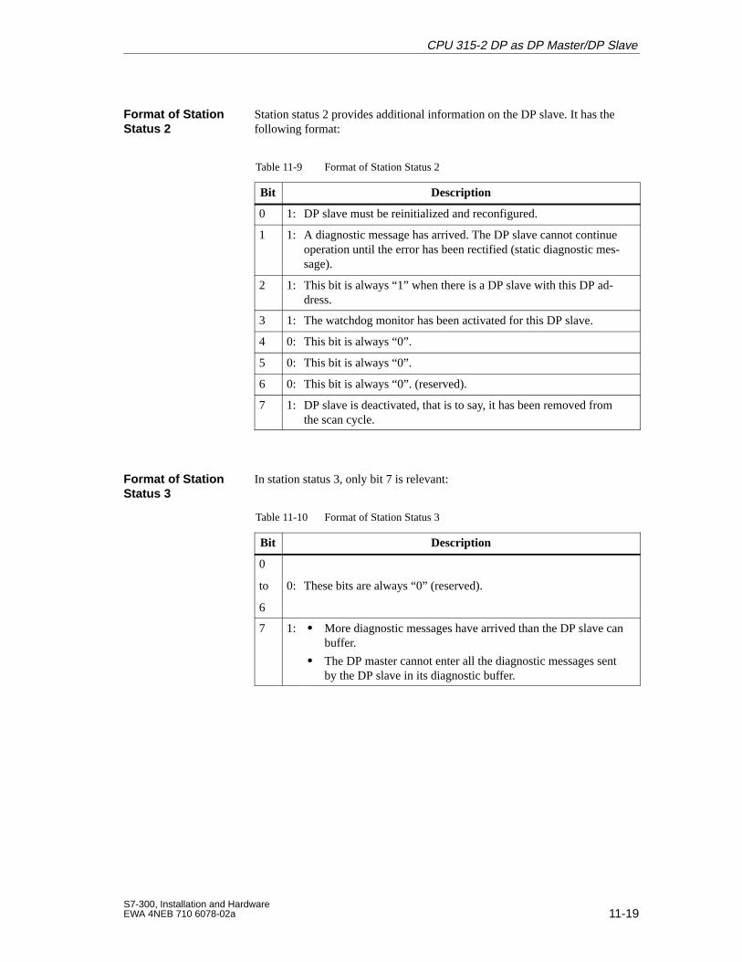
11-19S7-300, Installation and HardwareEWA 4NEB 710 6078-02a
Station status 2 provides additional information on the DP slave. It has thefollowing format:
Table 11-9 Format of Station Status 2
Bit Description
0 1: DP slave must be reinitialized and reconfigured.
1 1: A diagnostic message has arrived. The DP slave cannot continueoperation until the error has been rectified (static diagnostic mes-sage).
2 1: This bit is always “1” when there is a DP slave with this DP ad-dress.
3 1: The watchdog monitor has been activated for this DP slave.
4 0: This bit is always “0”.
5 0: This bit is always “0”.
6 0: This bit is always “0”. (reserved).
7 1: DP slave is deactivated, that is to say, it has been removed fromthe scan cycle.
In station status 3, only bit 7 is relevant:
Table 11-10 Format of Station Status 3
Bit Description
0
to
6
0: These bits are always “0” (reserved).
7 1: More diagnostic messages have arrived than the DP slave canbuffer.
The DP master cannot enter all the diagnostic messages sentby the DP slave in its diagnostic buffer.
Format of StationStatus 2
Format of StationStatus 3
CPU 315-2 DP as DP Master/DP Slave
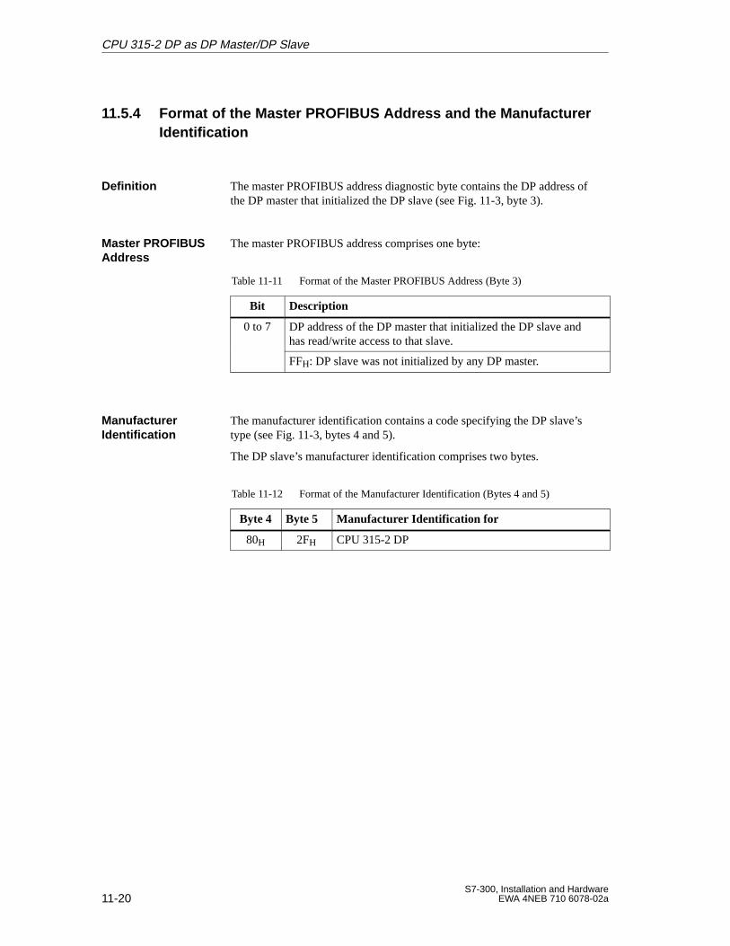
11-20S7-300, Installation and Hardware
EWA 4NEB 710 6078-02a
11.5.4 Format of the Master PROFIBUS Address and the Manufacturer Identification
The master PROFIBUS address diagnostic byte contains the DP address ofthe DP master that initialized the DP slave (see Fig. 11-3, byte 3).
The master PROFIBUS address comprises one byte:
Table 11-11 Format of the Master PROFIBUS Address (Byte 3)
Bit Description
0 to 7 DP address of the DP master that initialized the DP slave andhas read/write access to that slave.
FFH: DP slave was not initialized by any DP master.
The manufacturer identification contains a code specifying the DP slave’stype (see Fig. 11-3, bytes 4 and 5).
The DP slave’s manufacturer identification comprises two bytes.
Table 11-12 Format of the Manufacturer Identification (Bytes 4 and 5)
Byte 4 Byte 5 Manufactur er Identification for
80H 2FH CPU 315-2 DP
Definition
Master PROFIBUSAddress
Manufacturer Identification
CPU 315-2 DP as DP Master/DP Slave
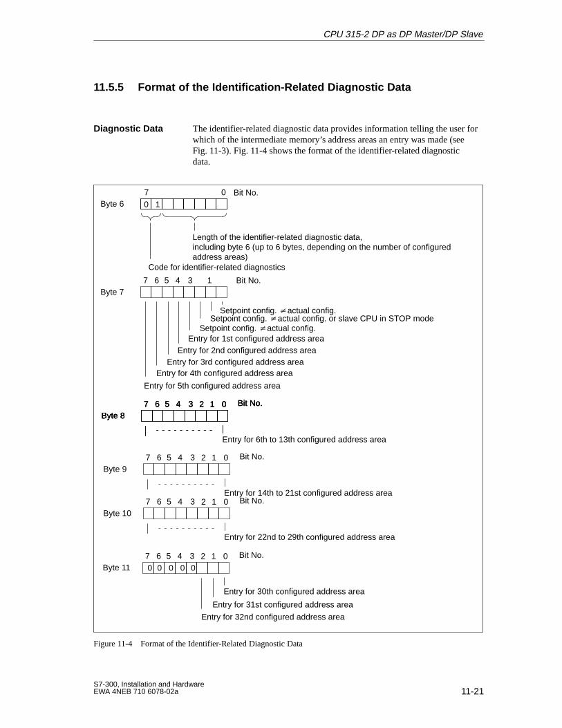
11-21S7-300, Installation and HardwareEWA 4NEB 710 6078-02a
11.5.5 Format of the Identification-Related Diagnostic Data
The identifier-related diagnostic data provides information telling the user forwhich of the intermediate memory’s address areas an entry was made (seeFig. 11-3). Fig. 11-4 shows the format of the identifier-related diagnosticdata.
Byte 67 0 Bit No.
Length of the identifier-related diagnostic data, including byte 6 (up to 6 bytes, depending on the number of configuredaddress areas)
Byte 7
Setpoint config. actual config. or slave CPU in STOP mode
Entry for 2nd configured address areaEntry for 3rd configured address area
Entry for 4th configured address area
Entry for 5th configured address area
Byte 8
Entry for 6th to 13th configured address area
Code for identifier-related diagnostics
0 1
7 6 5 4 1
02 1
3
Entry for 1st configured address area
Bit No.
Bit No.7 6 5 4 3
Byte 11
Entry for 30th configured address area
Entry for 31st configured address area
02 1 Bit No.7 6 5 4 3
Byte 802 1 Bit No.7 6 5 4 3
Byte 802 1 Bit No.7 6 5 4 3
Byte 9
Entry for 14th to 21st configured address area
02 1 Bit No.7 6 5 4 3
Byte 10
Entry for 22nd to 29th configured address area
02 1 Bit No.7 6 5 4 3
Entry for 32nd configured address area
00 00 0
Setpoint config. actual config.
Setpoint config. actual config.
Figure 11-4 Format of the Identifier-Related Diagnostic Data
Diagnostic Data
CPU 315-2 DP as DP Master/DP Slave
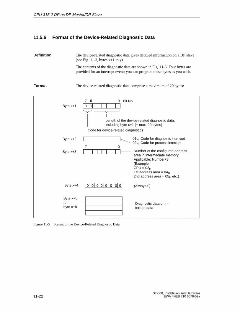
11-22S7-300, Installation and Hardware
EWA 4NEB 710 6078-02a
11.5.6 Format of the Device-Related Diagnostic Data
The device-related diagnostic data gives detailed information on a DP slave(see Fig. 11-3, bytes x+1 to y).
The contents of the diagnostic data are shown in Fig. 11-6. Four bytes areprovided for an interrupt event; you can program these bytes as you wish.
The device-related diagnostic data comprise a maximum of 20 bytes:
Byte x+2 01H: Code for diagnostic interrupt02H: Code for process interrupt
Byte x+5tobyte x+8
Byte x+17 0 Bit No.
Length of the device-related diagnostic data, including byte x+1 (= max. 20 bytes)
Code for device-related diagnostics
0 0
6
Byte x+3
Byte x+4
Number of the configured addressarea in intermediate memoryApplicable: Number+3(Example:CPU = 02H1st address area = 04H2nd address area = 05H etc.)
(Always 0)
Diagnostic data or in-terrupt data
7 0
0 0 0 0 0 0 0 0
Figure 11-5 Format of the Device-Related Diagnostic Data
Definition
Format
CPU 315-2 DP as DP Master/DP Slave
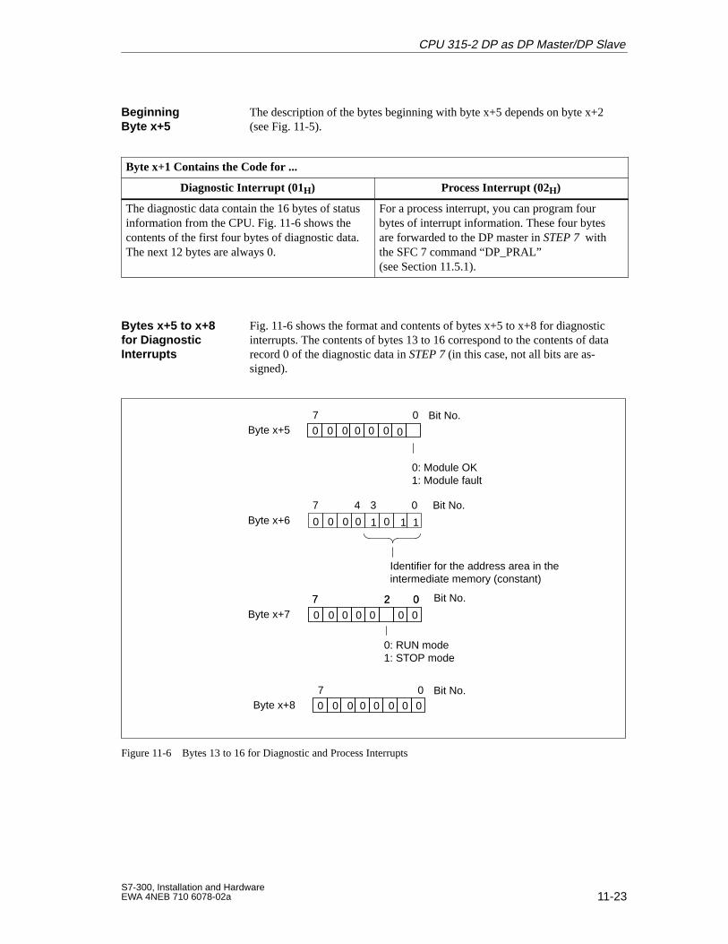
11-23S7-300, Installation and HardwareEWA 4NEB 710 6078-02a
The description of the bytes beginning with byte x+5 depends on byte x+2(see Fig. 11-5).
Byte x+1 Contains the Code for ...
Diagnostic Interrupt (01H) Process Interrupt (02H)
The diagnostic data contain the 16 bytes of statusinformation from the CPU. Fig. 11-6 shows thecontents of the first four bytes of diagnostic data.The next 12 bytes are always 0.
For a process interrupt, you can program four bytes of interrupt information. These four bytesare forwarded to the DP master in STEP 7 withthe SFC 7 command “DP_PRAL” (see Section 11.5.1).
Fig. 11-6 shows the format and contents of bytes x+5 to x+8 for diagnosticinterrupts. The contents of bytes 13 to 16 correspond to the contents of datarecord 0 of the diagnostic data in STEP 7 (in this case, not all bits are as-signed).
Byte x+57 0 Bit No.
Byte x+6
Byte x+7
0: RUN mode1: STOP mode
0: Module OK1: Module fault
0
1
0 0 0 0
1
7 4 0
02
3 Bit No.
Bit No.7 027
0 0
0 0 00 01
Identifier for the address area in theintermediate memory (constant)
0000000
Byte x+87 0 Bit No.0 0 0 0 00 0 0
Figure 11-6 Bytes 13 to 16 for Diagnostic and Process Interrupts
Beginning Byte x+5
Bytes x+5 to x+8for Diagnostic Interrupts
CPU 315-2 DP as DP Master/DP Slave
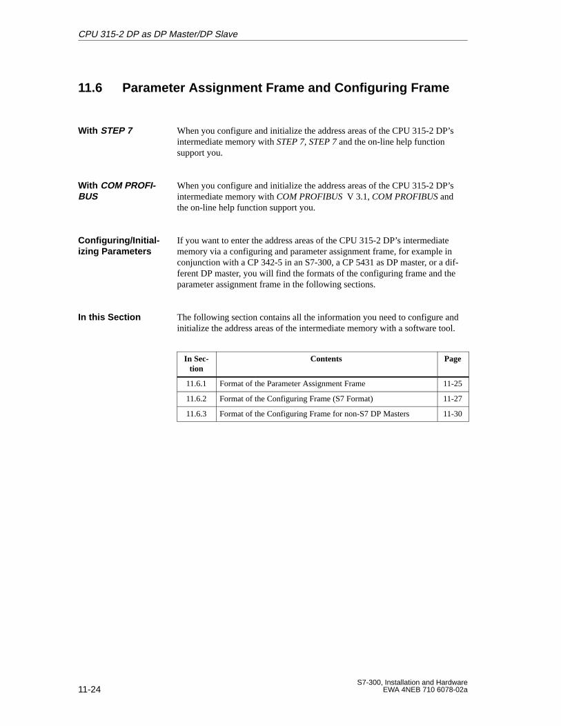
11-24S7-300, Installation and Hardware
EWA 4NEB 710 6078-02a
11.6 Parameter Assignment Frame and Configuring Frame
When you configure and initialize the address areas of the CPU 315-2 DP’sintermediate memory with STEP 7, STEP 7 and the on-line help functionsupport you.
When you configure and initialize the address areas of the CPU 315-2 DP’sintermediate memory with COM PROFIBUS V 3.1, COM PROFIBUS andthe on-line help function support you.
If you want to enter the address areas of the CPU 315-2 DP’s intermediatememory via a configuring and parameter assignment frame, for example inconjunction with a CP 342-5 in an S7-300, a CP 5431 as DP master, or a dif-ferent DP master, you will find the formats of the configuring frame and theparameter assignment frame in the following sections.
The following section contains all the information you need to configure andinitialize the address areas of the intermediate memory with a software tool.
In Sec-tion
Contents Page
11.6.1 Format of the Parameter Assignment Frame 11-25
11.6.2 Format of the Configuring Frame (S7 Format) 11-27
11.6.3 Format of the Configuring Frame for non-S7 DP Masters 11-30
With STEP 7
With COM PROFI-BUS
Configuring/Initial-izing Parameters
In this Section
CPU 315-2 DP as DP Master/DP Slave
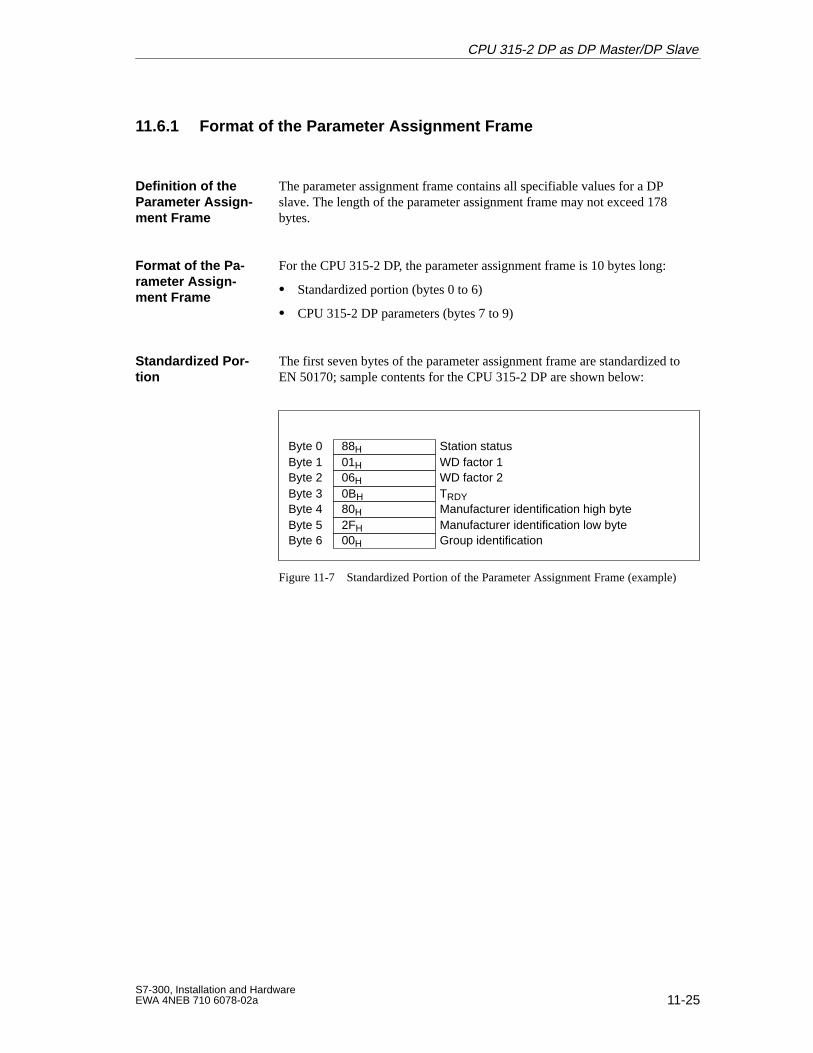
11-25S7-300, Installation and HardwareEWA 4NEB 710 6078-02a
11.6.1 Format of the Parameter Assignment Frame
The parameter assignment frame contains all specifiable values for a DPslave. The length of the parameter assignment frame may not exceed 178bytes.
For the CPU 315-2 DP, the parameter assignment frame is 10 bytes long:
Standardized portion (bytes 0 to 6)
CPU 315-2 DP parameters (bytes 7 to 9)
The first seven bytes of the parameter assignment frame are standardized toEN 50170; sample contents for the CPU 315-2 DP are shown below:
Byte 3
WD factor 1
TRDY
Station status
WD factor 2
Manufacturer identification high byte
Byte 0Byte 1Byte 2
Byte 4
01H
0BH
88H
06H
80HByte 5 Manufacturer identification low byte
Group identificationByte 62FH00H
Figure 11-7 Standardized Portion of the Parameter Assignment Frame (example)
Definition of theParameter Assign -ment Frame
Format of the Pa -rameter Assign -ment Frame
Standardized Por -tion
CPU 315-2 DP as DP Master/DP Slave
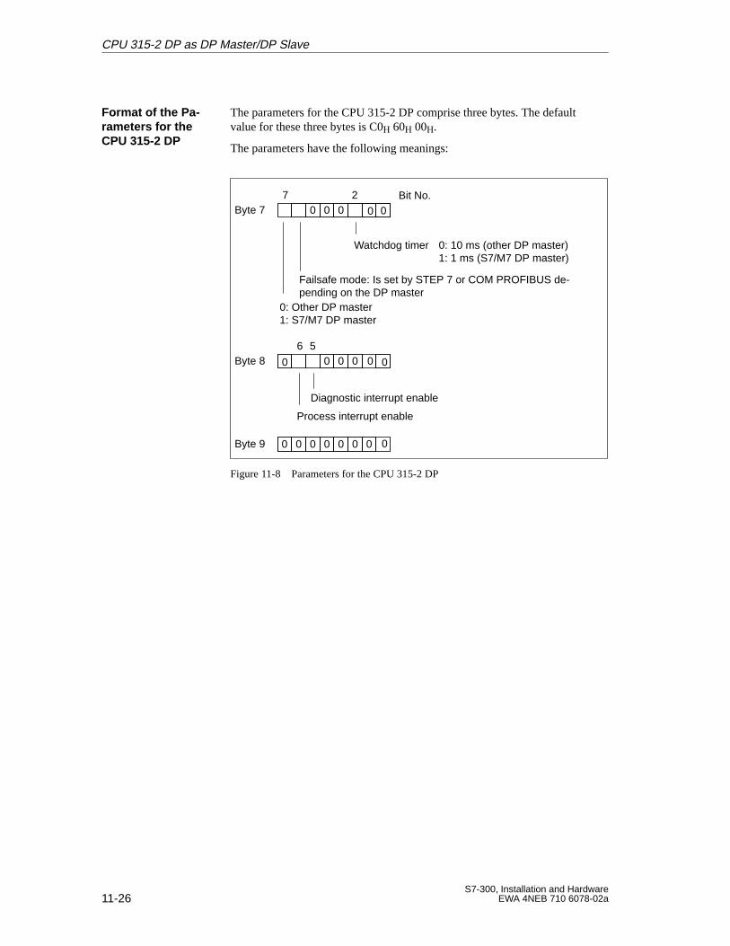
11-26S7-300, Installation and Hardware
EWA 4NEB 710 6078-02a
The parameters for the CPU 315-2 DP comprise three bytes. The defaultvalue for these three bytes is C0H 60H 00H.
The parameters have the following meanings:
Byte 77 Bit No.
0: Other DP master1: S7/M7 DP master
Byte 86
Process interrupt enable
Diagnostic interrupt enable
5
Byte 9
Watchdog timer 0: 10 ms (other DP master)1: 1 ms (S7/M7 DP master)
2000
0000
0000000
0 0
0
0
0
Failsafe mode: Is set by STEP 7 or COM PROFIBUS de-pending on the DP master
Figure 11-8 Parameters for the CPU 315-2 DP
Format of the Pa-rameters for theCPU 315-2 DP
CPU 315-2 DP as DP Master/DP Slave
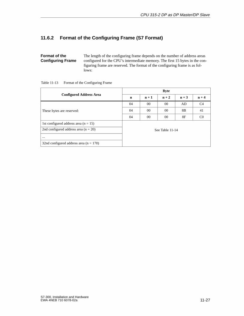
11-27S7-300, Installation and HardwareEWA 4NEB 710 6078-02a
11.6.2 Format of the Configuring Frame (S7 Format)
The length of the configuring frame depends on the number of address areasconfigured for the CPU’s intermediate memory. The first 15 bytes in the con-figuring frame are reserved. The format of the configuring frame is as fol-lows:
Table 11-13 Format of the Configuring Frame
Configured Address AreaByte
Configured Address Arean n + 1 n + 2 n + 3 n + 4
04 00 00 AD C4
These bytes are reserved: 04 00 00 8B 41y
04 00 00 8F C0
1st configured address area (n = 15)
2nd configured address area (n = 20) See Table 11-14
...
32nd configured address area (n = 170)
Format of the Configuring Frame
CPU 315-2 DP as DP Master/DP Slave
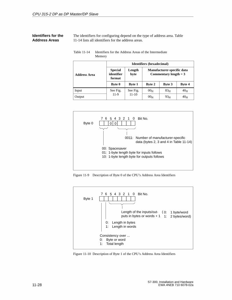
11-28S7-300, Installation and Hardware
EWA 4NEB 710 6078-02a
The identifiers for configuring depend on the type of address area. Table11-14 lists all identifiers for the address areas.
Table 11-14 Identifiers for the Address Areas of the IntermediateMemory
Identifiers (hexadecimal)
Address AreaSpecial
identifierformat
Lengthbyte
Manufacturer-specific dataCommentary length = 3
Byte 0 Byte 1 Byte 2 Byte 3 Byte 4
Input See Fig.11 9
See Fig.11 10
00H 83H 40H
Output
g11-9
g11-10
00H 93H 40H
Byte 07 0 Bit No.6 45 3 12
0011: Number of manufacturer-specific data (bytes 2, 3 and 4 in Table 11-14)
00
00: Spacesaver01: 1-byte length byte for inputs follows10: 1-byte length byte for outputs follows
Figure 11-9 Description of Byte 0 of the CPU’s Address Area Identifiers
Byte 17 0 Bit No.6 45 3 12
Length of the inputs/out-puts in bytes or words + 1
0: Length in bytes1: Length in words
Consistency over ...0: Byte or word1: Total length
0: 1 byte/word1: 2 bytes/word)
(
Figure 11-10 Description of Byte 1 of the CPU’s Address Area Identifiers
Identifiers for theAddress Areas
CPU 315-2 DP as DP Master/DP Slave
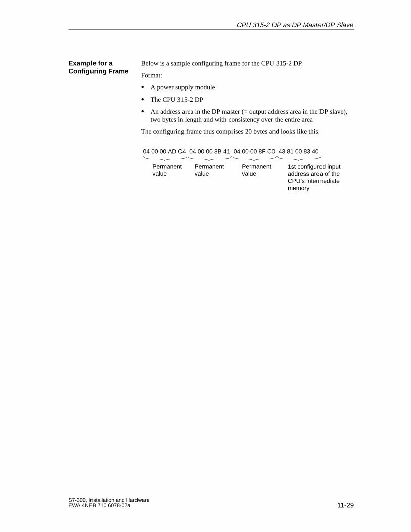
11-29S7-300, Installation and HardwareEWA 4NEB 710 6078-02a
Below is a sample configuring frame for the CPU 315-2 DP.
Format:
A power supply module
The CPU 315-2 DP
An address area in the DP master (= output address area in the DP slave),two bytes in length and with consistency over the entire area
The configuring frame thus comprises 20 bytes and looks like this:
04 00 00 AD C4 04 00 00 8B 41 04 00 00 8F C0 43 81 00 83 40
1st configured inputaddress area of theCPU’s intermediatememory
Permanentvalue
Permanentvalue
Permanentvalue
Example for a Configuring Frame
CPU 315-2 DP as DP Master/DP Slave
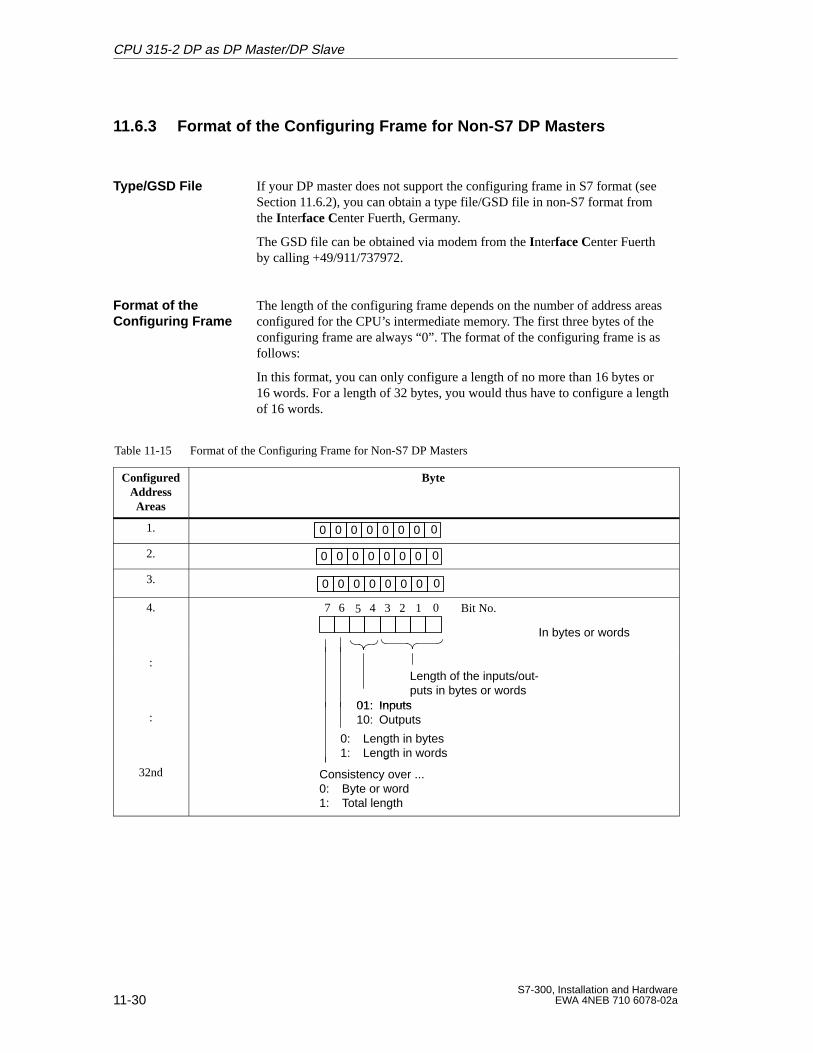
11-30S7-300, Installation and Hardware
EWA 4NEB 710 6078-02a
11.6.3 Format of the Configuring Frame for Non-S7 DP Masters
If your DP master does not support the configuring frame in S7 format (seeSection 11.6.2), you can obtain a type file/GSD file in non-S7 format fromthe Interface Center Fuerth, Germany.
The GSD file can be obtained via modem from the Interface Center Fuerthby calling +49/911/737972.
The length of the configuring frame depends on the number of address areasconfigured for the CPU’s intermediate memory. The first three bytes of theconfiguring frame are always “0”. The format of the configuring frame is asfollows:
In this format, you can only configure a length of no more than 16 bytes or16 words. For a length of 32 bytes, you would thus have to configure a lengthof 16 words.
Table 11-15 Format of the Configuring Frame for Non-S7 DP Masters
ConfiguredAddressAreas
Byte
1. 0000000 0
2. 0000000 0
3. 0000000 0
4. 7 0 Bit No.6 45 3 12
In bytes or words
:Length of the inputs/out-puts in bytes or words
01: Inputs:
0: Length in bytes1: Length in words
01: Inputs10: Outputs
32nd
1: Length in words
Consistency over ...0: Byte or word1: Total length
Type/GSD File
Format of the Configuring Frame
CPU 315-2 DP as DP Master/DP Slave
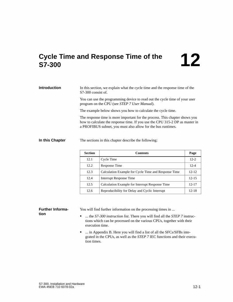
12-1S7-300, Installation and HardwareEWA 4NEB 710 6078-02a
Cycle Time and Response Time of theS7-300
In this section, we explain what the cycle time and the response time of theS7-300 consist of.
You can use the programming device to read out the cycle time of your userprogram on the CPU (see STEP 7 User Manual).
The example below shows you how to calculate the cycle time.
The response time is more important for the process. This chapter shows youhow to calculate the response time. If you use the CPU 315-2 DP as master ina PROFIBUS subnet, you must also allow for the bus runtimes.
The sections in this chapter describe the following:
Section Contents Page
12.1 Cycle Time 12-2
12.2 Response Time 12-4
12.3 Calculation Example for Cycle Time and Response Time 12-12
12.4 Interrupt Response Time 12-15
12.5 Calculation Example for Interrupt Response Time 12-17
12.6 Reproducibility for Delay and Cyclic Interrupt 12-18
You will find further information on the processing times in ...
... the S7-300 instruction list. There you will find all the STEP 7 instruc-tions which can be processed on the various CPUs, together with theirexecution time.
... in Appendix B. Here you will find a list of all the SFCs/SFBs inte-grated in the CPUs, as well as the STEP 7 IEC functions and their execu-tion times.
Introduction
In this Chapter
Further Informa -tion
12
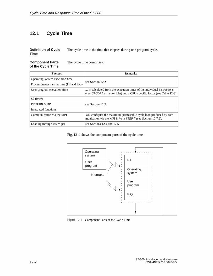
12-2S7-300, Installation and Hardware
EWA 4NEB 710 6078-02a
12.1 Cycle Time
The cycle time is the time that elapses during one program cycle.
The cycle time comprises:
Factors Remarks
Operating system execution timesee Section 12 2
Process image transfer time (PII and PIQ)see Section 12.2
User program execution time ... is calculated from the execution times of the individual instructions(see S7-300 Instruction List) and a CPU-specific factor (see Table 12-3)
S7 timers
PROFIBUS DP see Section 12.2
Integrated functions
Communication via the MPI You configure the maximum permissible cycle load produced by com-munication via the MPI in % in STEP 7 (see Section 10.7.2).
Loading through interrupts see Sections 12.4 and 12.5
Fig. 12-1 shows the component parts of the cycle time
PII
Operatingsystem
User program
PIQ
Interrupts
Operatingsystem
User program
Figure 12-1 Component Parts of the Cycle Time
Definition of CycleTime
Component Partsof the Cycle Time
Cycle Time and Response Time of the S7-300

12-3S7-300, Installation and HardwareEWA 4NEB 710 6078-02a
Note that the cycle time of a user program is extended by the following:
Time-controlled interrupt handling
Process interrupt handling (see also Section 12.4)
Diagnostics and error handling (see also Section 12.4)
Communication via MPI
Extension of theCycle T ime
Cycle Time and Response Time of the S7-300
12-4S7-300, Installation and Hardware
EWA 4NEB 710 6078-02a
12.2 Response Time
The response time is the time between detection of an input signal and modi-fication of an associated output signal.
The response time depends on the cycle time and the following factors:
Factors Remarks
Delay of the inputs and outputs The delay times are given in the technical specifications
In the Module Specifications Reference Manual for the signalmodules
In Section 10.8.1 for the integrated inputs and outputs of theCPU 312 IFM
In Section 10.8.4 for the integrated inputs and outputs of theCPU 314 IFM.
Additional bus runtimes on the PROFIBUS sub-net
CPU 315-2 DP only
The actual response time lies between a shortest and a longest response time.You must always reckon on the longest response time when configuring yoursystem.
The shortest and longest response times are considered below to let you getan idea of the width of fluctuation of the response time.
Definition of theResponse Time
Factors
Fluctuation Width
Cycle Time and Response Time of the S7-300
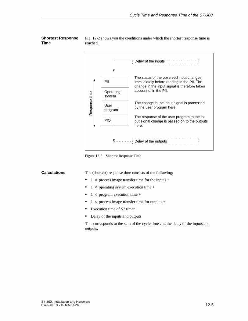
12-5S7-300, Installation and HardwareEWA 4NEB 710 6078-02a
Fig. 12-2 shows you the conditions under which the shortest response time isreached.
Operatingsystem
User program
PIIThe status of the observed input changesimmediately before reading in the PII. Thechange in the input signal is therefore takenaccount of in the PII.
PIQ
The change in the input signal is processedby the user program here.
The response of the user program to the in-put signal change is passed on to the outputshere.
Res
pons
e tim
e
Delay of the inputs
Delay of the outputs
Figure 12-2 Shortest Response Time
The (shortest) response time consists of the following:
1 process image transfer time for the inputs +
1 operating system execution time +
1 program execution time +
1 process image transfer time for outputs +
Execution time of S7 timer
Delay of the inputs and outputs
This corresponds to the sum of the cycle time and the delay of the inputs andoutputs.
Shortest ResponseTime
Calculations
Cycle Time and Response Time of the S7-300
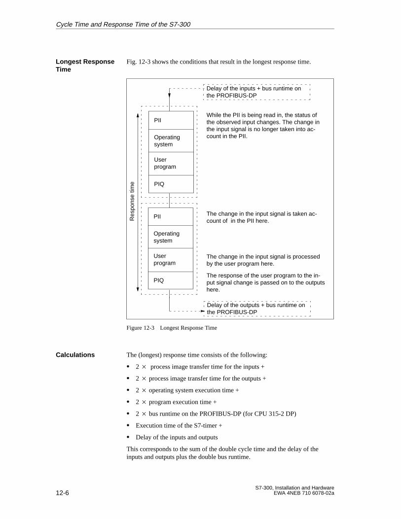
12-6S7-300, Installation and Hardware
EWA 4NEB 710 6078-02a
Fig. 12-3 shows the conditions that result in the longest response time.
Operatingsystem
User program
PIIWhile the PII is being read in, the status ofthe observed input changes. The change inthe input signal is no longer taken into ac-count in the PII.
PIQ
The change in the input signal is taken ac-count of in the PII here.
The change in the input signal is processedby the user program here.
The response of the user program to the in-put signal change is passed on to the outputshere.
Res
pons
e tim
e
Delay of the inputs + bus runtime onthe PROFIBUS-DP
Delay of the outputs + bus runtime onthe PROFIBUS-DP
Operatingsystem
User program
PII
PIQ
Figure 12-3 Longest Response Time
The (longest) response time consists of the following:
2 process image transfer time for the inputs +
2 process image transfer time for the outputs +
2 operating system execution time +
2 program execution time +
2 bus runtime on the PROFIBUS-DP (for CPU 315-2 DP)
Execution time of the S7-timer +
Delay of the inputs and outputs
This corresponds to the sum of the double cycle time and the delay of theinputs and outputs plus the double bus runtime.
Longest ResponseTime
Calculations
Cycle Time and Response Time of the S7-300
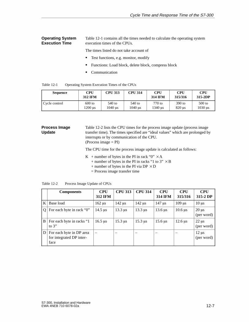
12-7S7-300, Installation and HardwareEWA 4NEB 710 6078-02a
Table 12-1 contains all the times needed to calculate the operating systemexecution times of the CPUs.
The times listed do not take account of
Test functions, e.g. monitor, modify
Functions: Load block, delete block, compress block
Communication
Table 12-1 Operating System Execution Times of the CPUs
Sequence CPU312 IFM
CPU 313 CPU 314 CPU314 IFM
CPU315/316
CPU315-2DP
Cycle control 600 to1200 s
540 to1040 s
540 to1040 s
770 to1340 s
390 to820 s
500 to1030 s
Table 12-2 lists the CPU times for the process image update (process imagetransfer time). The times specified are “ideal values” which are prolonged byinterrupts or by communication of the CPU.(Process image = PI)
The CPU time for the process image update is calculated as follows:
K + number of bytes in the PI in rack “0” A + number of bytes in the PI in racks “1 to 3” B+ number of bytes in the PI via DP D= Process image transfer time
Table 12-2 Process Image Update of CPUs
Components CPU312 IFM
CPU 313 CPU 314 CPU314 IFM
CPU315/316
CPU315-2 DP
K Base load 162 s 142 s 142 s 147 s 109 s 10 s
Q For each byte in rack “0” 14.5 s 13.3 s 13.3 s 13.6 s 10.6 s 20 s(per word)
B For each byte in racks “1to 3”
16.5 s 15.3 s 15.3 s 15.6 s 12.6 s 22 s(per word)
D For each byte in DP areafor integrated DP inter-face
– – – – – 12 s(per word)
Operating SystemExecution Time
Process Image Update
Cycle Time and Response Time of the S7-300
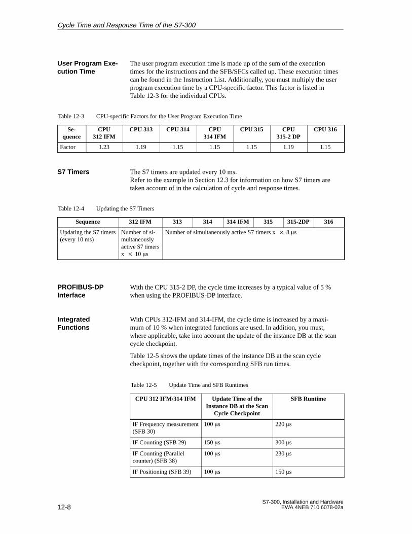
12-8S7-300, Installation and Hardware
EWA 4NEB 710 6078-02a
The user program execution time is made up of the sum of the executiontimes for the instructions and the SFB/SFCs called up. These execution timescan be found in the Instruction List. Additionally, you must multiply the userprogram execution time by a CPU-specific factor. This factor is listed inTable 12-3 for the individual CPUs.
Table 12-3 CPU-specific Factors for the User Program Execution Time
Se-quence
CPU312 IFM
CPU 313 CPU 314 CPU314 IFM
CPU 315 CPU315-2 DP
CPU 316
Factor 1.23 1.19 1.15 1.15 1.15 1.19 1.15
The S7 timers are updated every 10 ms.Refer to the example in Section 12.3 for information on how S7 timers aretaken account of in the calculation of cycle and response times.
Table 12-4 Updating the S7 Timers
Sequence 312 IFM 313 314 314 IFM 315 315-2DP 316
Updating the S7 timers(every 10 ms)
Number of si-multaneouslyactive S7 timersx 10 s
Number of simultaneously active S7 timers x 8 s
With the CPU 315-2 DP, the cycle time increases by a typical value of 5 %when using the PROFIBUS-DP interface.
With CPUs 312-IFM and 314-IFM, the cycle time is increased by a maxi-mum of 10 % when integrated functions are used. In addition, you must,where applicable, take into account the update of the instance DB at the scancycle checkpoint.
Table 12-5 shows the update times of the instance DB at the scan cyclecheckpoint, together with the corresponding SFB run times.
Table 12-5 Update Time and SFB Runtimes
CPU 312 IFM/314 IFM Update Time of theInstance DB at the Scan
Cycle Checkpoint
SFB Runtime
IF Frequency measurement(SFB 30)
100 s 220 s
IF Counting (SFB 29) 150 s 300 s
IF Counting (Parallelcounter) (SFB 38)
100 s 230 s
IF Positioning (SFB 39) 100 s 150 s
User Program Exe -cution Time
S7 Timers
PROFIBUS-DP Interface
Integrated Functions
Cycle Time and Response Time of the S7-300

12-9S7-300, Installation and HardwareEWA 4NEB 710 6078-02a
You must take account of the following delay times, depending on the mod-ule:
For digital inputs: The input delay time
For digital outputs: Negligible delay times
For relay outputs: Typical delay times of between 10 ms and 20 ms. The delay of the relay outputs depends, among other things, on the tem-perature and voltage.
For analog inputs: Cycle time of the analog input
For analog outputs: Response time of the analog output
Delay of I/Os
Cycle Time and Response Time of the S7-300
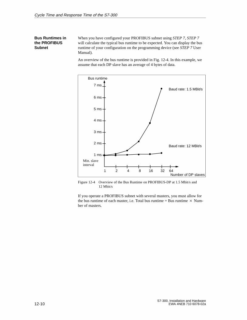
12-10S7-300, Installation and Hardware
EWA 4NEB 710 6078-02a
When you have configured your PROFIBUS subnet using STEP 7, STEP 7will calculate the typical bus runtime to be expected. You can display the busruntime of your configuration on the programming device (see STEP 7 UserManual).
An overview of the bus runtime is provided in Fig. 12-4. In this example, weassume that each DP slave has an average of 4 bytes of data.
Bus runtime
Number of DP slaves
6 ms
4 ms
2 ms
1 2 4 8 16 32
Baud rate: 12 MBit/s
Baud rate: 1.5 MBit/s
1 ms
3 ms
5 ms
7 ms
Min. slaveinterval
64
Figure 12-4 Overview of the Bus Runtime on PROFIBUS-DP at 1.5 Mbit/s and 12 Mbit/s
If you operate a PROFIBUS subnet with several masters, you must allow forthe bus runtime of each master, i.e. Total bus runtime = Bus runtime Num-ber of masters.
Bus Runtimes inthe PROFIBUSSubnet
Cycle Time and Response Time of the S7-300
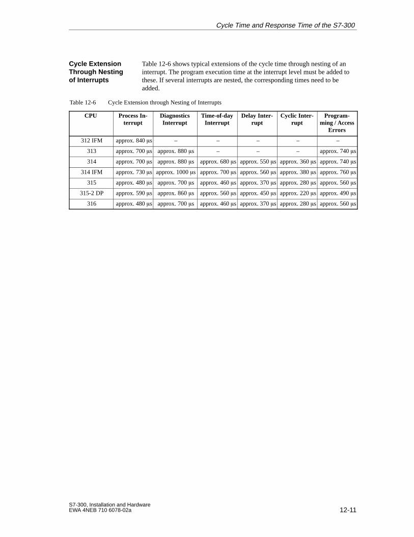
12-11S7-300, Installation and HardwareEWA 4NEB 710 6078-02a
Table 12-6 shows typical extensions of the cycle time through nesting of aninterrupt. The program execution time at the interrupt level must be added tothese. If several interrupts are nested, the corresponding times need to beadded.
Table 12-6 Cycle Extension through Nesting of Interrupts
CPU Process In-terrupt
DiagnosticsInterrupt
Time-of-dayInterrupt
Delay Inter-rupt
Cyclic Inter-rupt
Program-ming / Access
Errors
312 IFM approx. 840 s – – – – –
313 approx. 700 s approx. 880 s – – – approx. 740 s
314 approx. 700 s approx. 880 s approx. 680 s approx. 550 s approx. 360 s approx. 740 s
314 IFM approx. 730 s approx. 1000 s approx. 700 s approx. 560 s approx. 380 s approx. 760 s
315 approx. 480 s approx. 700 s approx. 460 s approx. 370 s approx. 280 s approx. 560 s
315-2 DP approx. 590 s approx. 860 s approx. 560 s approx. 450 s approx. 220 s approx. 490 s
316 approx. 480 s approx. 700 s approx. 460 s approx. 370 s approx. 280 s approx. 560 s
Cycle ExtensionThrough Nestingof Interrupts
Cycle Time and Response Time of the S7-300
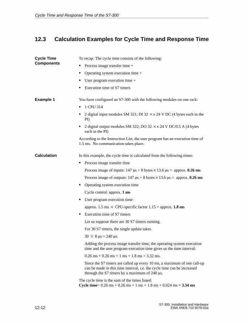
12-12S7-300, Installation and Hardware
EWA 4NEB 710 6078-02a
12.3 Calculation Examples for Cycle T ime and Response Time
To recap: The cycle time consists of the following:
Process image transfer time +
Operating system execution time +
User program execution time +
Execution time of S7 timers
You have configured an S7-300 with the following modules on one rack:
1 CPU 314
2 digital input modules SM 321; DI 32 x 24 V DC (4 bytes each in thePI)
2 digital output modules SM 322; DO 32 x 24 V DC/0.5 A (4 byteseach in the PI)
According to the Instruction List, the user program has an execution time of1.5 ms. No communication takes place.
In this example, the cycle time is calculated from the following times:
Process image transfer time
Process image of inputs: 147 s + 8 bytes13.6 s = approx. 0.26 ms
Process image of outputs: 147 s + 8 bytes13.6 s = approx. 0.26 ms
Operating system execution time
Cycle control: approx. 1 ms
User program execution time:
approx. 1.5 ms CPU-specific factor 1.15 = approx. 1.8 ms
Execution time of S7 timers
Let us suppose there are 30 S7 timers running.
For 30 S7 timers, the single update takes
30 8 s = 240s.
Adding the process image transfer time, the operating system executiontime and the user program execution time gives us the time interval:
0.26 ms + 0.26 ms + 1 ms + 1.8 ms = 3.32 ms.
Since the S7 timers are called up every 10 ms, a maximum of one call-upcan be made in this time interval, i.e. the cycle time can be increasedthrough the S7 timers by a maximum of 240 s.
The cycle time is the sum of the times listed:Cycle time= 0.26 ms + 0.26 ms + 1 ms + 1.8 ms + 0.024 ms = 3.34 ms
Cycle T ime Components
Example 1
Calculation
Cycle Time and Response Time of the S7-300
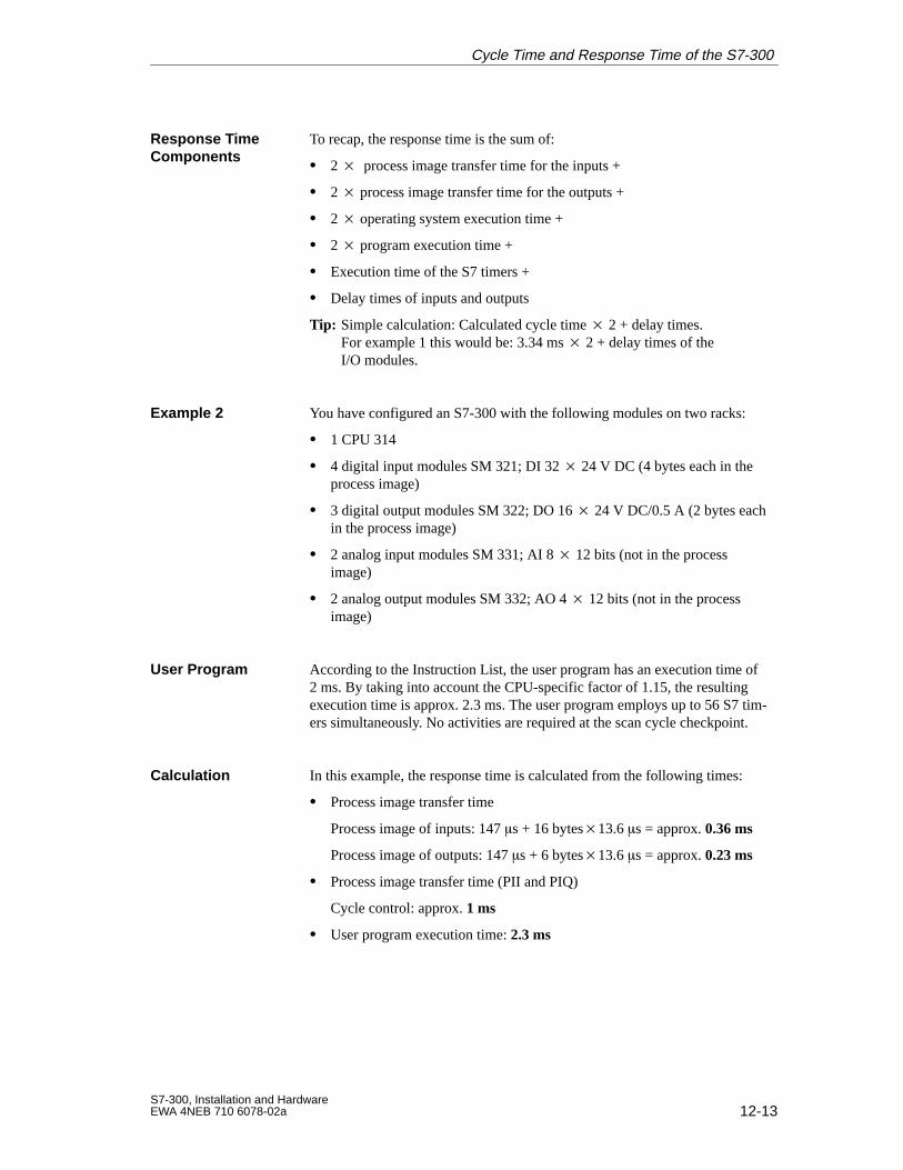
12-13S7-300, Installation and HardwareEWA 4NEB 710 6078-02a
To recap, the response time is the sum of:
2 process image transfer time for the inputs +
2 process image transfer time for the outputs +
2 operating system execution time +
2 program execution time +
Execution time of the S7 timers +
Delay times of inputs and outputs
Tip: Simple calculation: Calculated cycle time 2 + delay times.For example 1 this would be: 3.34 ms 2 + delay times of the I/O modules.
You have configured an S7-300 with the following modules on two racks:
1 CPU 314
4 digital input modules SM 321; DI 32 24 V DC (4 bytes each in theprocess image)
3 digital output modules SM 322; DO 16 24 V DC/0.5 A (2 bytes eachin the process image)
2 analog input modules SM 331; AI 8 12 bits (not in the processimage)
2 analog output modules SM 332; AO 4 12 bits (not in the processimage)
According to the Instruction List, the user program has an execution time of2 ms. By taking into account the CPU-specific factor of 1.15, the resultingexecution time is approx. 2.3 ms. The user program employs up to 56 S7 tim-ers simultaneously. No activities are required at the scan cycle checkpoint.
In this example, the response time is calculated from the following times:
Process image transfer time
Process image of inputs: 147 s + 16 bytes13.6 s = approx. 0.36 ms
Process image of outputs: 147 s + 6 bytes13.6 s = approx. 0.23 ms
Process image transfer time (PII and PIQ)
Cycle control: approx. 1 ms
User program execution time: 2.3 ms
Response TimeComponents
Example 2
User Program
Calculation
Cycle Time and Response Time of the S7-300
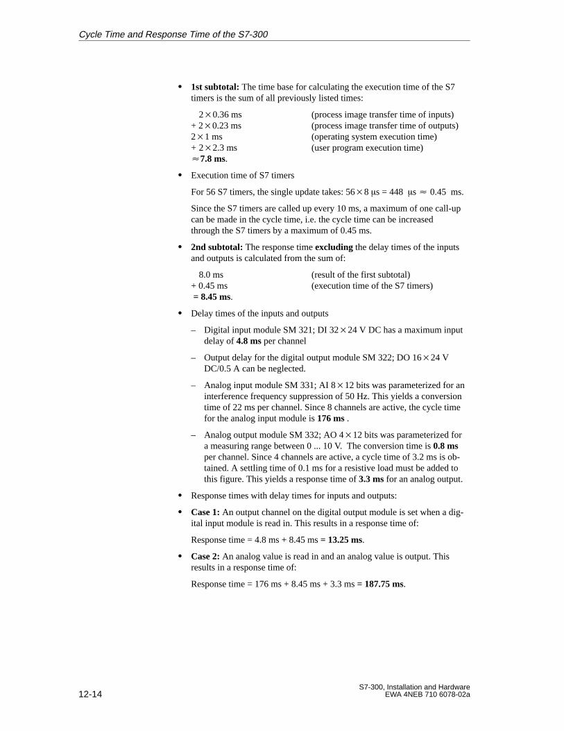
12-14S7-300, Installation and Hardware
EWA 4NEB 710 6078-02a
1st subtotal: The time base for calculating the execution time of the S7timers is the sum of all previously listed times:
20.36 ms (process image transfer time of inputs)+ 20.23 ms (process image transfer time of outputs)21 ms (operating system execution time)+ 22.3 ms (user program execution time) 7.8 ms.
Execution time of S7 timers
For 56 S7 timers, the single update takes: 568 s = 448 s 0.45 ms.
Since the S7 timers are called up every 10 ms, a maximum of one call-upcan be made in the cycle time, i.e. the cycle time can be increasedthrough the S7 timers by a maximum of 0.45 ms.
2nd subtotal: The response time excluding the delay times of the inputsand outputs is calculated from the sum of:
8.0 ms (result of the first subtotal)+ 0.45 ms (execution time of the S7 timers) = 8.45 ms.
Delay times of the inputs and outputs
– Digital input module SM 321; DI 3224 V DC has a maximum inputdelay of 4.8 ms per channel
– Output delay for the digital output module SM 322; DO 1624 VDC/0.5 A can be neglected.
– Analog input module SM 331; AI 812 bits was parameterized for aninterference frequency suppression of 50 Hz. This yields a conversiontime of 22 ms per channel. Since 8 channels are active, the cycle timefor the analog input module is 176 ms .
– Analog output module SM 332; AO 412 bits was parameterized fora measuring range between 0 ... 10 V. The conversion time is 0.8 msper channel. Since 4 channels are active, a cycle time of 3.2 ms is ob-tained. A settling time of 0.1 ms for a resistive load must be added tothis figure. This yields a response time of 3.3 ms for an analog output.
Response times with delay times for inputs and outputs:
Case 1: An output channel on the digital output module is set when a dig-ital input module is read in. This results in a response time of:
Response time = 4.8 ms + 8.45 ms = 13.25 ms.
Case 2: An analog value is read in and an analog value is output. Thisresults in a response time of:
Response time = 176 ms + 8.45 ms + 3.3 ms = 187.75 ms.
Cycle Time and Response Time of the S7-300
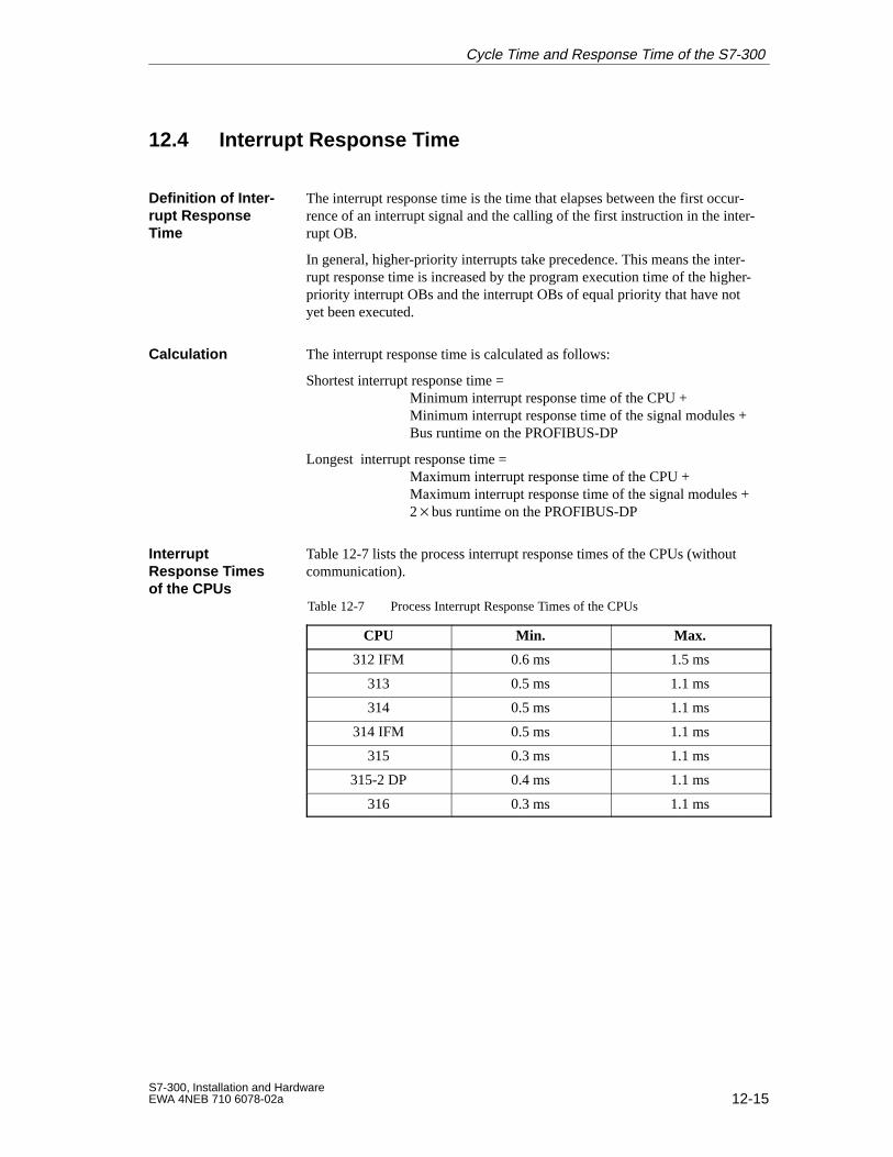
12-15S7-300, Installation and HardwareEWA 4NEB 710 6078-02a
12.4 Interrupt Response T ime
The interrupt response time is the time that elapses between the first occur-rence of an interrupt signal and the calling of the first instruction in the inter-rupt OB.
In general, higher-priority interrupts take precedence. This means the inter-rupt response time is increased by the program execution time of the higher-priority interrupt OBs and the interrupt OBs of equal priority that have notyet been executed.
The interrupt response time is calculated as follows:
Shortest interrupt response time = Minimum interrupt response time of the CPU +
Minimum interrupt response time of the signal modules +Bus runtime on the PROFIBUS-DP
Longest interrupt response time = Maximum interrupt response time of the CPU +
Maximum interrupt response time of the signal modules +2bus runtime on the PROFIBUS-DP
Table 12-7 lists the process interrupt response times of the CPUs (withoutcommunication).
Table 12-7 Process Interrupt Response Times of the CPUs
CPU Min. Max.
312 IFM 0.6 ms 1.5 ms
313 0.5 ms 1.1 ms
314 0.5 ms 1.1 ms
314 IFM 0.5 ms 1.1 ms
315 0.3 ms 1.1 ms
315-2 DP 0.4 ms 1.1 ms
316 0.3 ms 1.1 ms
Definition of Inter-rupt ResponseTime
Calculation
Interrupt Response T imes of the CPUs
Cycle Time and Response Time of the S7-300
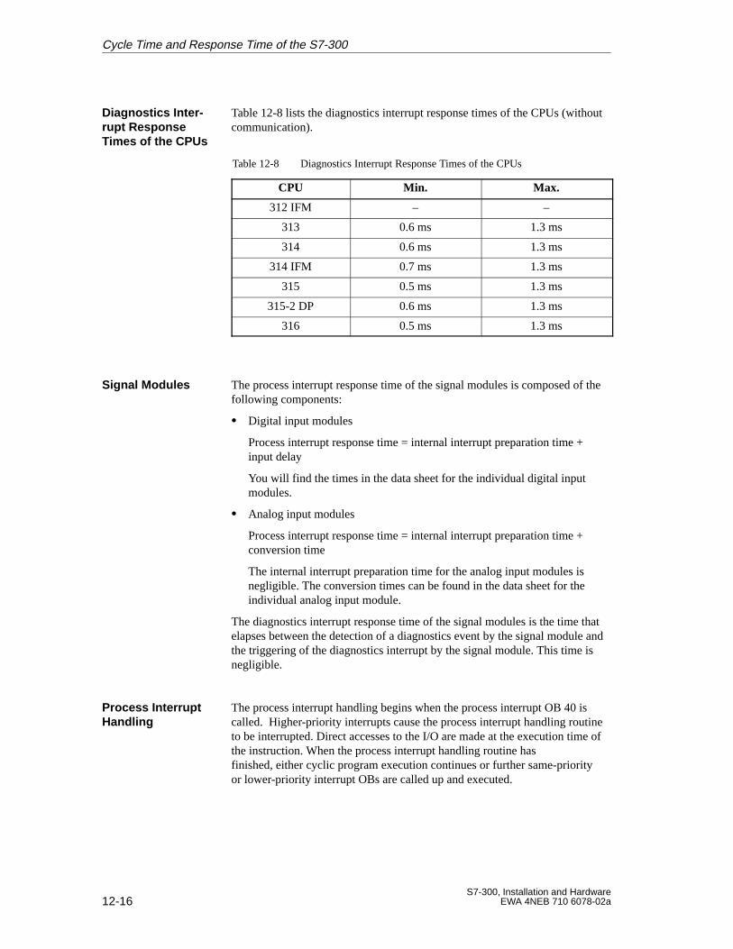
12-16S7-300, Installation and Hardware
EWA 4NEB 710 6078-02a
Table 12-8 lists the diagnostics interrupt response times of the CPUs (withoutcommunication).
Table 12-8 Diagnostics Interrupt Response Times of the CPUs
CPU Min. Max.
312 IFM – –
313 0.6 ms 1.3 ms
314 0.6 ms 1.3 ms
314 IFM 0.7 ms 1.3 ms
315 0.5 ms 1.3 ms
315-2 DP 0.6 ms 1.3 ms
316 0.5 ms 1.3 ms
The process interrupt response time of the signal modules is composed of thefollowing components:
Digital input modules
Process interrupt response time = internal interrupt preparation time +input delay
You will find the times in the data sheet for the individual digital inputmodules.
Analog input modules
Process interrupt response time = internal interrupt preparation time +conversion time
The internal interrupt preparation time for the analog input modules isnegligible. The conversion times can be found in the data sheet for theindividual analog input module.
The diagnostics interrupt response time of the signal modules is the time thatelapses between the detection of a diagnostics event by the signal module andthe triggering of the diagnostics interrupt by the signal module. This time isnegligible.
The process interrupt handling begins when the process interrupt OB 40 iscalled. Higher-priority interrupts cause the process interrupt handling routineto be interrupted. Direct accesses to the I/O are made at the execution time ofthe instruction. When the process interrupt handling routine has finished, either cyclic program execution continues or further same-priorityor lower-priority interrupt OBs are called up and executed.
Diagnostics Inter -rupt ResponseTimes of the CPUs
Signal Modules
Process InterruptHandling
Cycle Time and Response Time of the S7-300
12-17S7-300, Installation and HardwareEWA 4NEB 710 6078-02a
12.5 Calculation Example for the Interrupt Response Time
To recap, the process interrupt response time is composed of:
The process interrupt response time of the CPU and
The process interrupt response time of the signal module.
Example: You have configured an S7-300 with a CPU 314 and four digitalmodules. One of the digital modules is the SM 321; DI 1624 V DC withprocess and diagnostics interrupts. You have only enabled the process inter-rupt when setting the parameters for the CPU and the SM. You decided not touse time-controlled processing, diagnostics or error handling. You configuredan input delay of 0.5 ms for the digital input module. No activities are neces-sary at the scan cycle checkpoint. There is no communication via the MPI.
The process interrupt response time in this example is calculated from thefollowing times:
Process interrupt response time of the CPU 314: approx. 1.1 ms
Process interrupt response time of the SM 321; DI 1624 V DC:
– Internal interrupt preparation time:0.25 ms
– Input delay: 0.5 ms
The process interrupt response time is calculated from the sum of times:
Process interrupt response time = 1.1 ms + 0.25 ms + 0.5 ms = approx. 1.85 ms.
This process interrupt response time elapses from the time a signal is appliedto the digital input until the first instruction in OB 40.
Interrupt Re-sponse T ime Components
Calculation
Cycle Time and Response Time of the S7-300
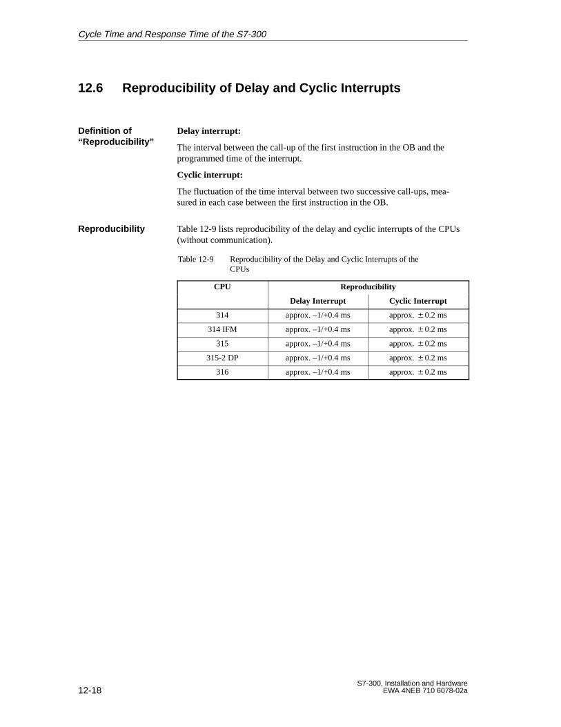
12-18S7-300, Installation and Hardware
EWA 4NEB 710 6078-02a
12.6 Reproducibility of Delay and Cyclic Interrupts
Delay interrupt:
The interval between the call-up of the first instruction in the OB and theprogrammed time of the interrupt.
Cyclic interrupt:
The fluctuation of the time interval between two successive call-ups, mea-sured in each case between the first instruction in the OB.
Table 12-9 lists reproducibility of the delay and cyclic interrupts of the CPUs(without communication).
Table 12-9 Reproducibility of the Delay and Cyclic Interrupts of theCPUs
CPU Reproducibility
Delay Interrupt Cyclic Interrupt
314 approx. –1/+0.4 ms approx. 0.2 ms
314 IFM approx. –1/+0.4 ms approx. 0.2 ms
315 approx. –1/+0.4 ms approx. 0.2 ms
315-2 DP approx. –1/+0.4 ms approx. 0.2 ms
316 approx. –1/+0.4 ms approx. 0.2 ms
Definition of “Reproducibility”
Reproducibility
Cycle Time and Response Time of the S7-300
A-1S7-300, Installation and HardwareEWA 4NEB 710 6078-02a
Standards and Approvals
This Appendix provides the following information on the S7-300 modulesand components:
The most important standards and criteria met by S7-300 and
Approvals that have been granted for the S7-300.
The S7-300 programmable controller meets the requirements and criteria tostandard IEC 1131, Part 2.
Our products meet the requirements and protection guidelines of the follow-ing EC Directives and comply with the harmonized European standards (EN)issued in the Official Journal of the European Communities with regard toprogrammable controllers:
89/336/EEC “Electromagnetic Compatibility” (EMC Directive)
73/23/EEC “Electrical Equipment Designed for Use between CertainVoltage Limits” (Low-Voltage Directive)
The declarations of conformity are held at the address below, where they canbe obtained if and when required by the respective authorities:
Siemens AktiengesellschaftAutomation Group A&D AS E 4P.O. Box 1963D-92209 AmbergFederal Republic of Germany
SIMATIC products have been designed for use in the industrial area.
They can also be used in residential environments (residential, commer-cial and light industry) with individual approval. You must acquire the indi-vidual approval from the respective national authority or testing body. InDeutschland erteilt die Einzelgenehmigung das Bundesamt für Post und Tele-kommunikation und seine Nebenstellen.
Area of Application Requirements:
Emitted interference
Immunity
Industry EN 50081-2 : 1993 EN 50082-2 : 1995
Domestic Individual approval EN 50082-1 : 1992
Introduction
IEC 1131
CE Marking
EMC Directive
A
A-2S7-300, Installation and Hardware
EWA 4NEB 710 6078-02a
UL Recognition MarkUnderwriters Laboratories (UL) toUL standard 508, Report 116536
CSA Certification MarkCanadian Standard Association (CSA) toC22.2 standard No. 142, Report LR 48323
FM Approval to Factory Mutual Approval Standard Class Number 3611,Class I, Division 2, Group A, B, C, D.
!Warning
Personal injury or property damage can result.
In hazardous areas, personal injury or property damage can result if youwithdraw any connectors while an S7-300 is in operation.
Always isolate the S7-300 in hazardous areas before withdrawing connec-tors.
The CPU 315-2 DP has received PNO certificate no.: Z00258 (as DP slave)
UL Approval
CSA Approval
FM Approval
PNO (PROFIBUSuser organization)(CPU 315-2 DP)only
Standards and Approvals
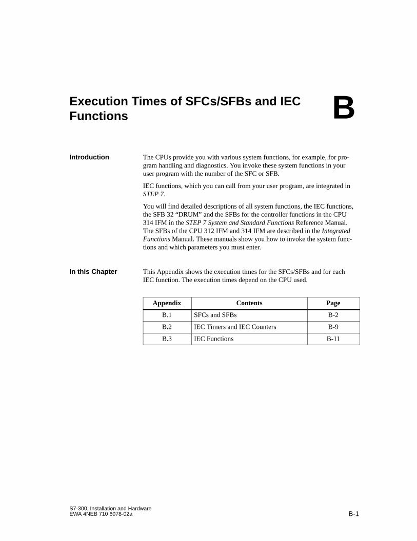
B-1S7-300, Installation and HardwareEWA 4NEB 710 6078-02a
Execution Times of SFCs/SFBs and IECFunctions
The CPUs provide you with various system functions, for example, for pro-gram handling and diagnostics. You invoke these system functions in youruser program with the number of the SFC or SFB.
IEC functions, which you can call from your user program, are integrated inSTEP 7.
You will find detailed descriptions of all system functions, the IEC functions,the SFB 32 “DRUM” and the SFBs for the controller functions in the CPU314 IFM in the STEP 7 System and Standard Functions Reference Manual.The SFBs of the CPU 312 IFM and 314 IFM are described in the IntegratedFunctions Manual. These manuals show you how to invoke the system func-tions and which parameters you must enter.
This Appendix shows the execution times for the SFCs/SFBs and for eachIEC function. The execution times depend on the CPU used.
Appendix Contents Page
B.1 SFCs and SFBs B-2
B.2 IEC Timers and IEC Counters B-9
B.3 IEC Functions B-11
Introduction
In this Chapter
B
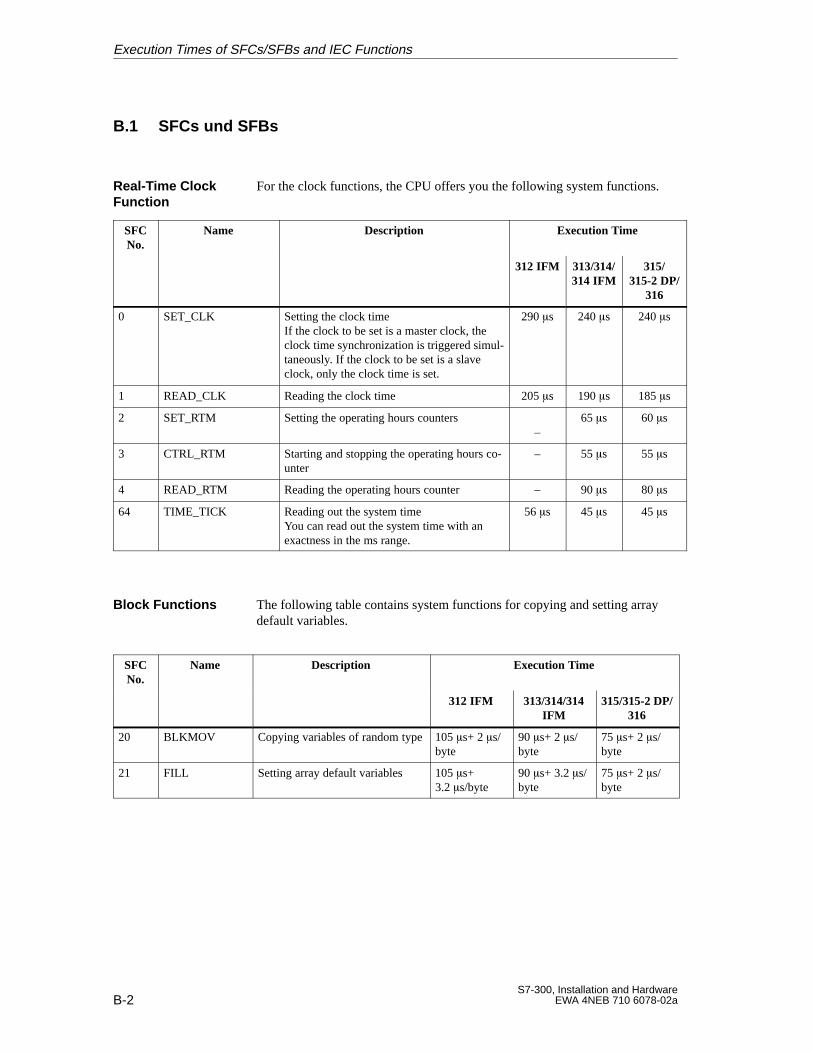
B-2S7-300, Installation and Hardware
EWA 4NEB 710 6078-02a
B.1 SFCs und SFBs
For the clock functions, the CPU offers you the following system functions.
SFCNo.
Name Description Execution Time
312 IFM 313/314/314 IFM
315/315-2 DP/
316
0 SET_CLK Setting the clock timeIf the clock to be set is a master clock, theclock time synchronization is triggered simul-taneously. If the clock to be set is a slaveclock, only the clock time is set.
290 s 240 s 240 s
1 READ_CLK Reading the clock time 205 s 190 s 185 s
2 SET_RTM Setting the operating hours counters–
65 s 60 s
3 CTRL_RTM Starting and stopping the operating hours co-unter
– 55 s 55 s
4 READ_RTM Reading the operating hours counter – 90 s 80 s
64 TIME_TICK Reading out the system timeYou can read out the system time with an exactness in the ms range.
56 s 45 s 45 s
The following table contains system functions for copying and setting arraydefault variables.
SFCNo.
Name Description Execution Time
312 IFM 313/314/314IFM
315/315-2 DP/316
20 BLKMOV Copying variables of random type105 s+ 2 s/byte
90 s+ 2 s/byte
75 s+ 2 s/byte
21 FILL Setting array default variables 105 s+3.2 s/byte
90 s+ 3.2 s/byte
75 s+ 2 s/byte
Real-Time ClockFunction
Block Functions
Execution Times of SFCs/SFBs and IEC Functions
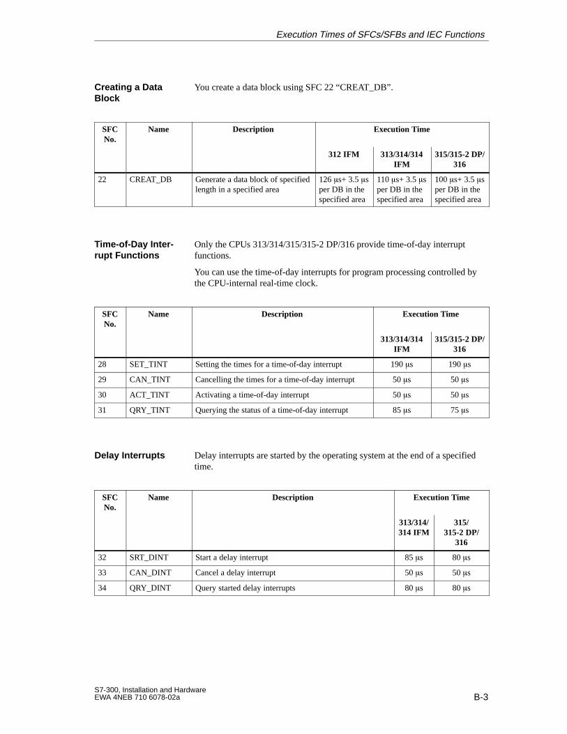
B-3S7-300, Installation and HardwareEWA 4NEB 710 6078-02a
You create a data block using SFC 22 “CREAT_DB”.
SFCNo.
Name Description Execution Time
312 IFM 313/314/314IFM
315/315-2 DP/316
22 CREAT_DB Generate a data block of specifiedlength in a specified area
126 s+ 3.5 sper DB in thespecified area
110 s+ 3.5 sper DB in thespecified area
100 s+ 3.5 sper DB in thespecified area
Only the CPUs 313/314/315/315-2 DP/316 provide time-of-day interruptfunctions.
You can use the time-of-day interrupts for program processing controlled bythe CPU-internal real-time clock.
SFCNo.
Name Description Execution Time
313/314/314IFM
315/315-2 DP/316
28 SET_TINT Setting the times for a time-of-day interrupt 190 s 190 s
29 CAN_TINT Cancelling the times for a time-of-day interrupt 50 s 50 s
30 ACT_TINT Activating a time-of-day interrupt 50 s 50 s
31 QRY_TINT Querying the status of a time-of-day interrupt 85 s 75 s
Delay interrupts are started by the operating system at the end of a specifiedtime.
SFCNo.
Name Description Execution Time
313/314/314 IFM
315/315-2 DP/
316
32 SRT_DINT Start a delay interrupt 85 s 80 s
33 CAN_DINT Cancel a delay interrupt 50 s 50 s
34 QRY_DINT Query started delay interrupts 80 s 80 s
Creating a DataBlock
Time-of-Day Inter -rupt Functions
Delay Interrupts
Execution Times of SFCs/SFBs and IEC Functions
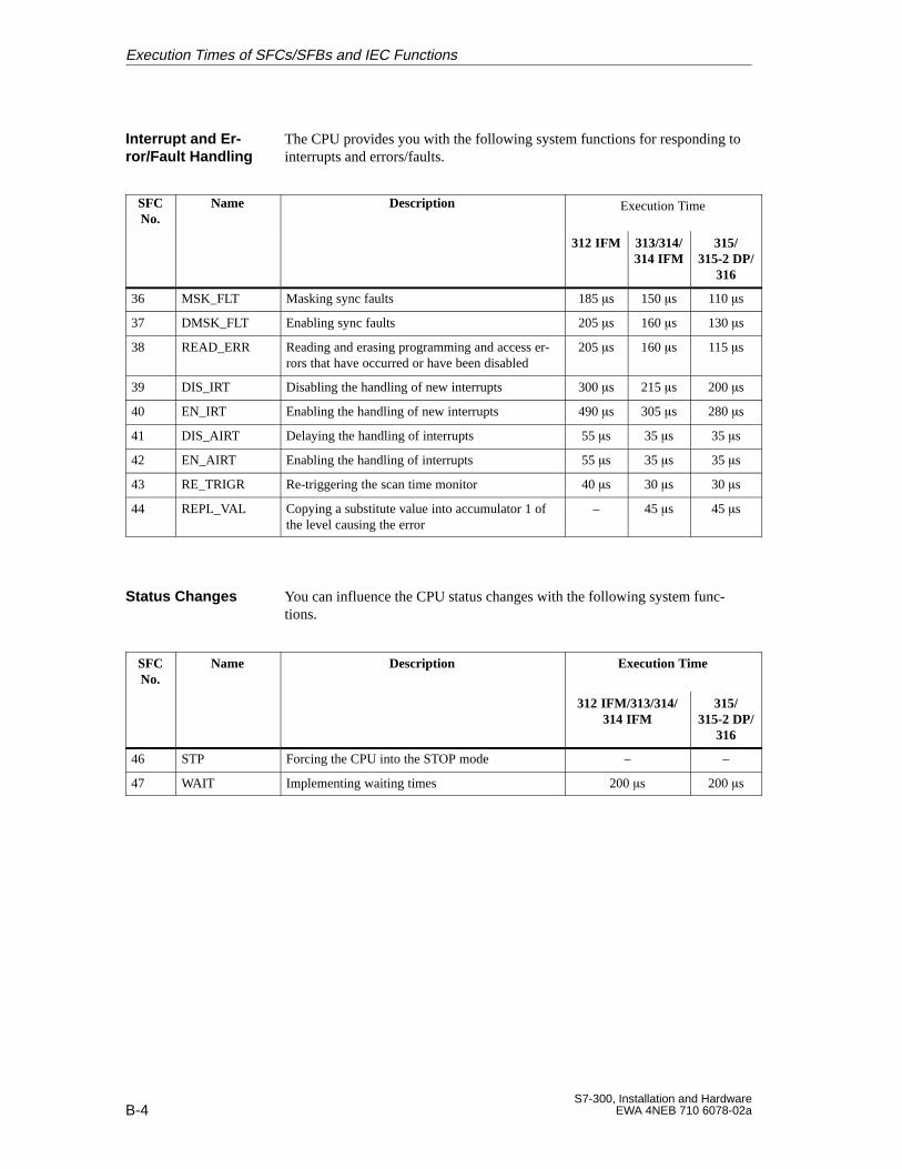
B-4S7-300, Installation and Hardware
EWA 4NEB 710 6078-02a
The CPU provides you with the following system functions for responding tointerrupts and errors/faults.
SFCNo.
Name Description Execution Time
312 IFM 313/314/314 IFM
315/315-2 DP/
316
36 MSK_FLT Masking sync faults 185 s 150 s 110 s
37 DMSK_FLT Enabling sync faults 205 s 160 s 130 s
38 READ_ERR Reading and erasing programming and access er-rors that have occurred or have been disabled
205 s 160 s 115 s
39 DIS_IRT Disabling the handling of new interrupts 300 s 215 s 200 s
40 EN_IRT Enabling the handling of new interrupts 490 s 305 s 280 s
41 DIS_AIRT Delaying the handling of interrupts 55 s 35 s 35 s
42 EN_AIRT Enabling the handling of interrupts 55 s 35 s 35 s
43 RE_TRIGR Re-triggering the scan time monitor 40 s 30 s 30 s
44 REPL_VAL Copying a substitute value into accumulator 1 ofthe level causing the error
– 45 s 45 s
You can influence the CPU status changes with the following system func-tions.
SFCNo.
Name Description Execution Time
312 IFM/313/314/314 IFM
315/315-2 DP/
316
46 STP Forcing the CPU into the STOP mode – –
47 WAIT Implementing waiting times 200 s 200 s
Interrupt and Er -ror/Fault Handling
Status Changes
Execution Times of SFCs/SFBs and IEC Functions
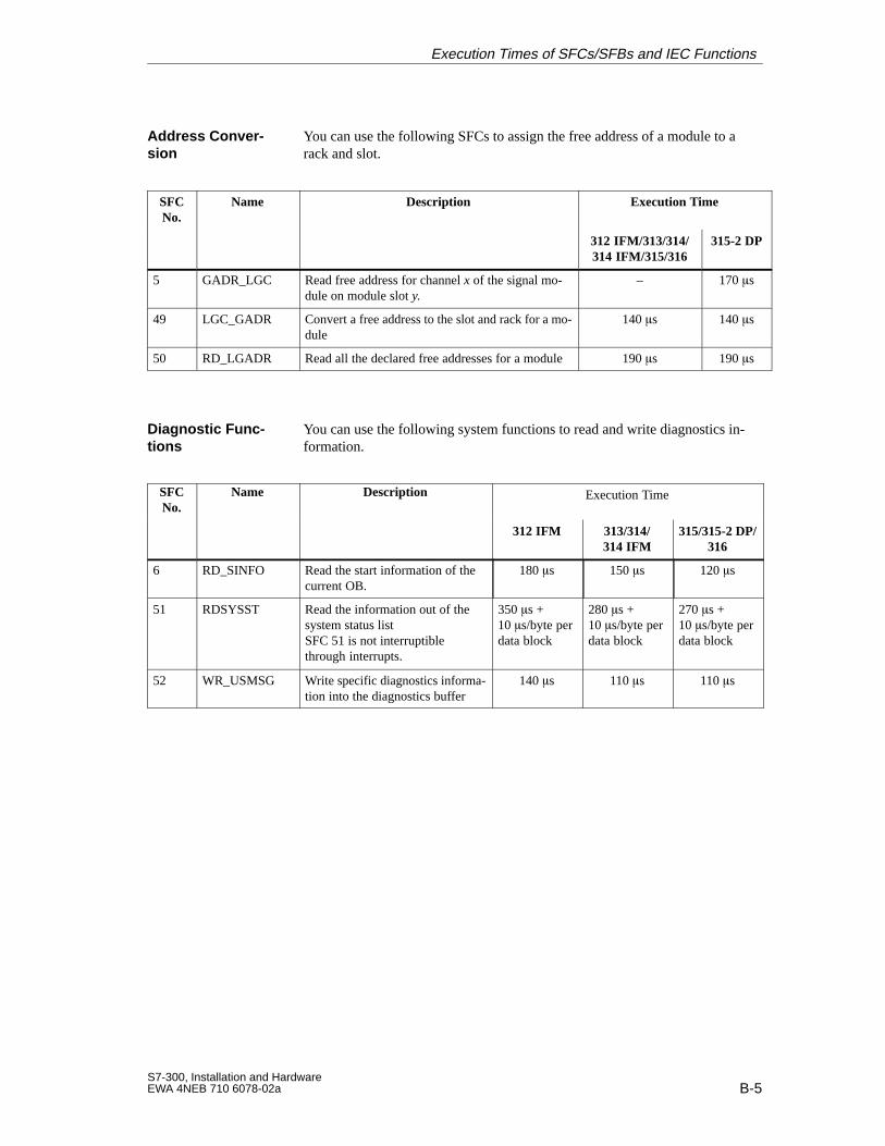
B-5S7-300, Installation and HardwareEWA 4NEB 710 6078-02a
You can use the following SFCs to assign the free address of a module to arack and slot.
SFCNo.
Name Description Execution Time
312 IFM/313/314/314 IFM/315/316
315-2 DP
5 GADR_LGC Read free address for channel x of the signal mo-dule on module slot y.
– 170 s
49 LGC_GADR Convert a free address to the slot and rack for a mo-dule
140 s 140 s
50 RD_LGADR Read all the declared free addresses for a module 190 s 190 s
You can use the following system functions to read and write diagnostics in-formation.
SFCNo.
Name Description Execution Time
312 IFM 313/314/314 IFM
315/315-2 DP/316
6 RD_SINFO Read the start information of thecurrent OB.
180 s 150 s 120 s
51 RDSYSST Read the information out of the system status listSFC 51 is not interruptiblethrough interrupts.
350 s +10 s/byte perdata block
280 s +10 s/byte perdata block
270 s +10 s/byte perdata block
52 WR_USMSG Write specific diagnostics informa-tion into the diagnostics buffer
140 s 110 s 110 s
Address Conver -sion
Diagnostic Func-tions
Execution Times of SFCs/SFBs and IEC Functions
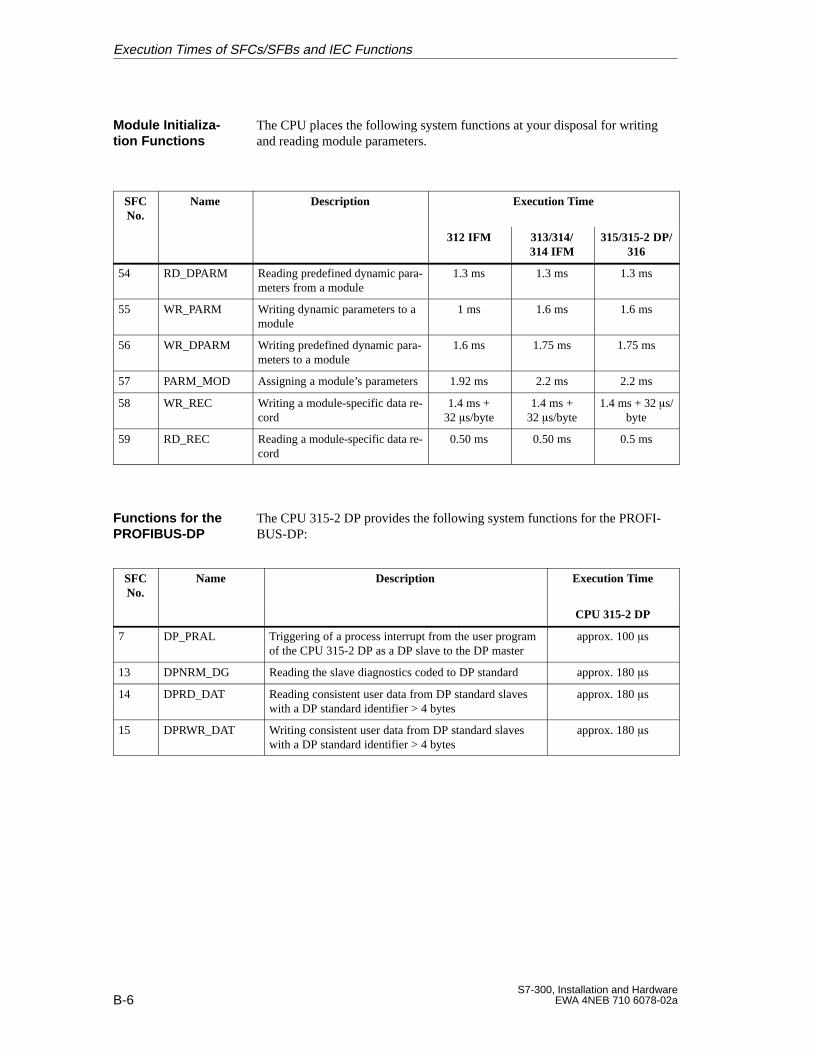
B-6S7-300, Installation and Hardware
EWA 4NEB 710 6078-02a
The CPU places the following system functions at your disposal for writingand reading module parameters.
SFCNo.
Name Description Execution Time
312 IFM 313/314/314 IFM
315/315-2 DP/316
54 RD_DPARM Reading predefined dynamic para-meters from a module
1.3 ms 1.3 ms 1.3 ms
55 WR_PARM Writing dynamic parameters to amodule
1 ms 1.6 ms 1.6 ms
56 WR_DPARM Writing predefined dynamic para-meters to a module
1.6 ms 1.75 ms 1.75 ms
57 PARM_MOD Assigning a module’s parameters 1.92 ms 2.2 ms 2.2 ms
58 WR_REC Writing a module-specific data re-cord
1.4 ms +32 s/byte
1.4 ms +32 s/byte
1.4 ms + 32 s/byte
59 RD_REC Reading a module-specific data re-cord
0.50 ms 0.50 ms 0.5 ms
The CPU 315-2 DP provides the following system functions for the PROFI-BUS-DP:
SFCNo.
Name Description Execution Time
CPU 315-2 DP
7 DP_PRAL Triggering of a process interrupt from the user programof the CPU 315-2 DP as a DP slave to the DP master
approx. 100 s
13 DPNRM_DG Reading the slave diagnostics coded to DP standard approx. 180 s
14 DPRD_DAT Reading consistent user data from DP standard slaveswith a DP standard identifier > 4 bytes
approx. 180 s
15 DPRWR_DAT Writing consistent user data from DP standard slaveswith a DP standard identifier > 4 bytes
approx. 180 s
Module Initializa -tion Functions
Functions for thePROFIBUS-DP
Execution Times of SFCs/SFBs and IEC Functions
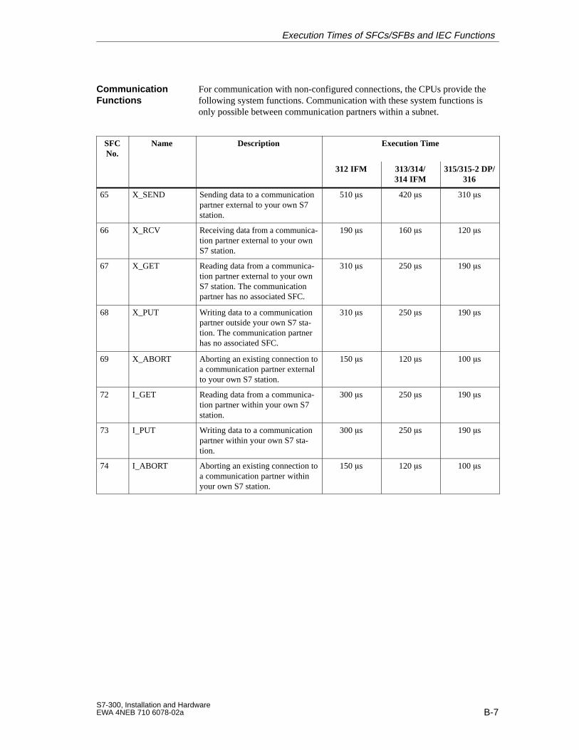
B-7S7-300, Installation and HardwareEWA 4NEB 710 6078-02a
For communication with non-configured connections, the CPUs provide thefollowing system functions. Communication with these system functions isonly possible between communication partners within a subnet.
SFCNo.
Name Description Execution Time
312 IFM 313/314/314 IFM
315/315-2 DP/316
65 X_SEND Sending data to a communicationpartner external to your own S7station.
510 s 420 s 310 s
66 X_RCV Receiving data from a communica-tion partner external to your ownS7 station.
190 s 160 s 120 s
67 X_GET Reading data from a communica-tion partner external to your ownS7 station. The communicationpartner has no associated SFC.
310 s 250 s 190 s
68 X_PUT Writing data to a communicationpartner outside your own S7 sta-tion. The communication partnerhas no associated SFC.
310 s 250 s 190 s
69 X_ABORT Aborting an existing connection toa communication partner externalto your own S7 station.
150 s 120 s 100 s
72 I_GET Reading data from a communica-tion partner within your own S7station.
300 s 250 s 190 s
73 I_PUT Writing data to a communicationpartner within your own S7 sta-tion.
300 s 250 s 190 s
74 I_ABORT Aborting an existing connection toa communication partner withinyour own S7 station.
150 s 120 s 100 s
CommunicationFunctions
Execution Times of SFCs/SFBs and IEC Functions
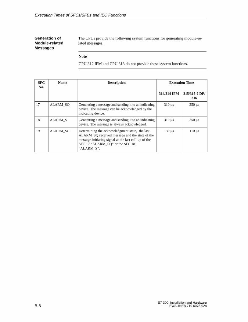
B-8S7-300, Installation and Hardware
EWA 4NEB 710 6078-02a
The CPUs provide the following system functions for generating module-re-lated messages.
Note
CPU 312 IFM and CPU 313 do not provide these system functions.
SFCNo.
Name Description Execution Time
314/314 IFM 315/315-2 DP/316
17 ALARM_SQ Generating a message and sending it to an indicatingdevice. The message can be acknowledged by theindicating device.
310 s 250 s
18 ALARM_S Generating a message and sending it to an indicatingdevice. The message is always acknowledged.
310 s 250 s
19 ALARM_SC Determining the acknowledgment state, the lastALARM_SQ received message and the state of themessage-initiating signal at the last call-up of theSFC 17 “ALARM_SQ” or the SFC 18“ALARM_S”.
130 s 110 s
Generation ofModule-relatedMessages
Execution Times of SFCs/SFBs and IEC Functions
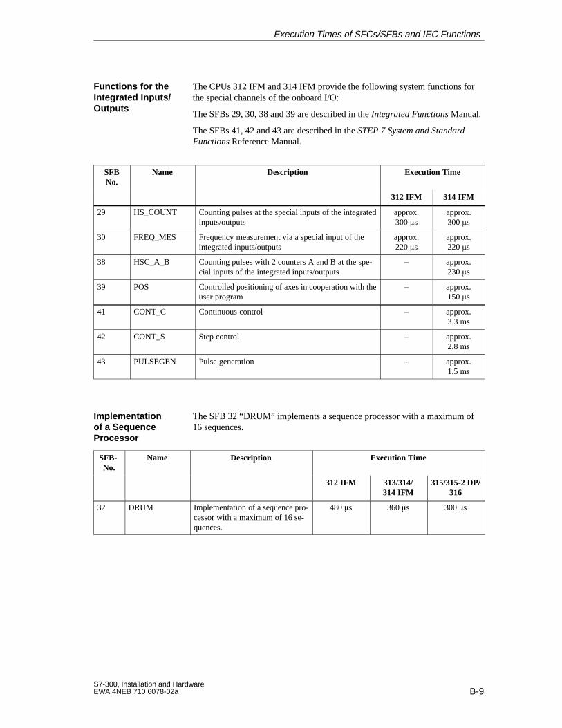
B-9S7-300, Installation and HardwareEWA 4NEB 710 6078-02a
The CPUs 312 IFM and 314 IFM provide the following system functions forthe special channels of the onboard I/O:
The SFBs 29, 30, 38 and 39 are described in the Integrated Functions Manual.
The SFBs 41, 42 and 43 are described in the STEP 7 System and StandardFunctions Reference Manual.
SFBNo.
Name Description Execution Time
312 IFM 314 IFM
29 HS_COUNT Counting pulses at the special inputs of the integratedinputs/outputs
approx.300 s
approx.300 s
30 FREQ_MES Frequency measurement via a special input of theintegrated inputs/outputs
approx.220 s
approx.220 s
38 HSC_A_B Counting pulses with 2 counters A and B at the spe-cial inputs of the integrated inputs/outputs
– approx.230 s
39 POS Controlled positioning of axes in cooperation with theuser program
– approx.150 s
41 CONT_C Continuous control – approx.3.3 ms
42 CONT_S Step control – approx.2.8 ms
43 PULSEGEN Pulse generation – approx.1.5 ms
The SFB 32 “DRUM” implements a sequence processor with a maximum of16 sequences.
SFB-No.
Name Description Execution Time
312 IFM 313/314/314 IFM
315/315-2 DP/316
32 DRUM Implementation of a sequence pro-cessor with a maximum of 16 se-quences.
480 s 360 s 300 s
Functions for theIntegrated Inputs/Outputs
Implementation of a Sequence Processor
Execution Times of SFCs/SFBs and IEC Functions
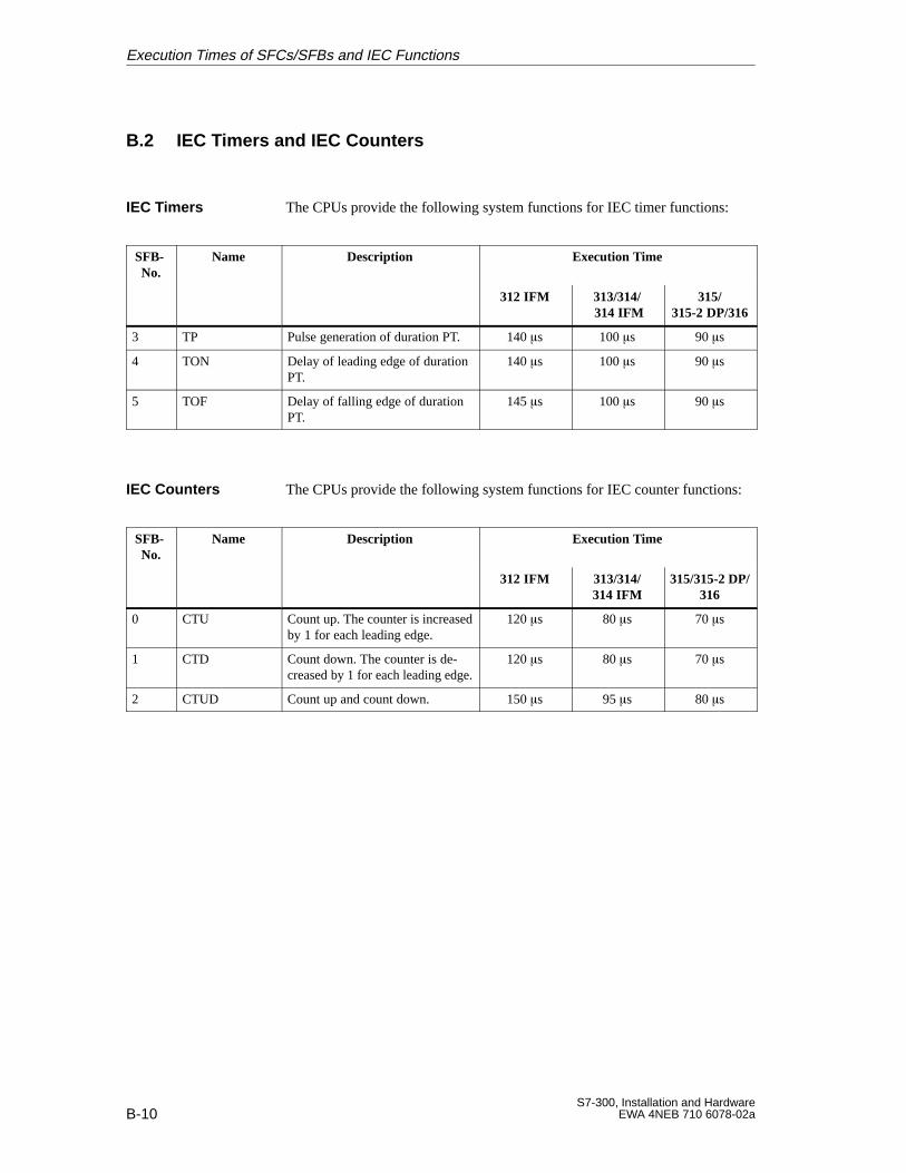
B-10S7-300, Installation and Hardware
EWA 4NEB 710 6078-02a
B.2 IEC Timers and IEC Counters
The CPUs provide the following system functions for IEC timer functions:
SFB-No.
Name Description Execution Time
312 IFM 313/314/ 314 IFM
315/315-2 DP/316
3 TP Pulse generation of duration PT. 140 s 100 s 90 s
4 TON Delay of leading edge of durationPT.
140 s 100 s 90 s
5 TOF Delay of falling edge of durationPT.
145 s 100 s 90 s
The CPUs provide the following system functions for IEC counter functions:
SFB-No.
Name Description Execution Time
312 IFM 313/314/314 IFM
315/315-2 DP/316
0 CTU Count up. The counter is increasedby 1 for each leading edge.
120 s 80 s 70 s
1 CTD Count down. The counter is de-creased by 1 for each leading edge.
120 s 80 s 70 s
2 CTUD Count up and count down. 150 s 95 s 80 s
IEC Timers
IEC Counters
Execution Times of SFCs/SFBs and IEC Functions
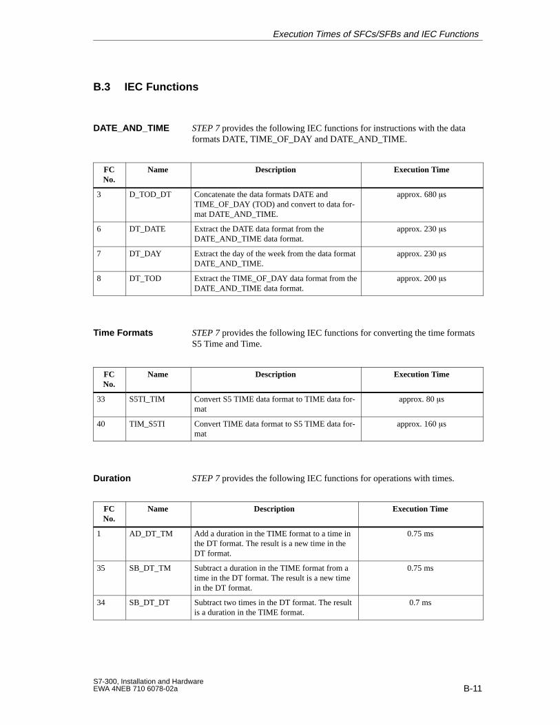
B-11S7-300, Installation and HardwareEWA 4NEB 710 6078-02a
B.3 IEC Functions
STEP 7 provides the following IEC functions for instructions with the dataformats DATE, TIME_OF_DAY and DATE_AND_TIME.
FCNo.
Name Description Execution Time
3 D_TOD_DT Concatenate the data formats DATE andTIME_OF_DAY (TOD) and convert to data for-mat DATE_AND_TIME.
approx. 680 s
6 DT_DATE Extract the DATE data format from theDATE_AND_TIME data format.
approx. 230 s
7 DT_DAY Extract the day of the week from the data formatDATE_AND_TIME.
approx. 230 s
8 DT_TOD Extract the TIME_OF_DAY data format from theDATE_AND_TIME data format.
approx. 200 s
STEP 7 provides the following IEC functions for converting the time formatsS5 Time and Time.
FCNo.
Name Description Execution Time
33 S5TI_TIM Convert S5 TIME data format to TIME data for-mat
approx. 80 s
40 TIM_S5TI Convert TIME data format to S5 TIME data for-mat
approx. 160 s
STEP 7 provides the following IEC functions for operations with times.
FCNo.
Name Description Execution Time
1 AD_DT_TM Add a duration in the TIME format to a time inthe DT format. The result is a new time in theDT format.
0.75 ms
35 SB_DT_TM Subtract a duration in the TIME format from atime in the DT format. The result is a new timein the DT format.
0.75 ms
34 SB_DT_DT Subtract two times in the DT format. The resultis a duration in the TIME format.
0.7 ms
DATE_AND_TIME
Time Formats
Duration
Execution Times of SFCs/SFBs and IEC Functions
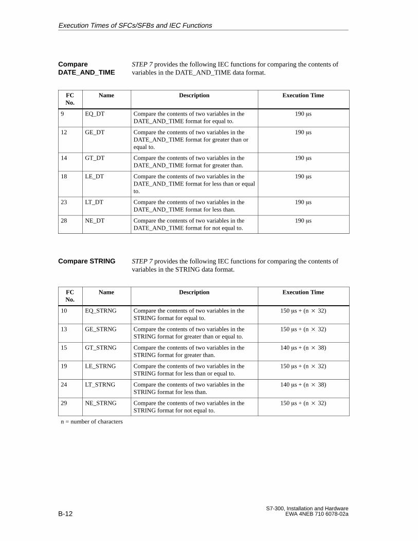
B-12S7-300, Installation and Hardware
EWA 4NEB 710 6078-02a
STEP 7 provides the following IEC functions for comparing the contents ofvariables in the DATE_AND_TIME data format.
FCNo.
Name Description Execution Time
9 EQ_DT Compare the contents of two variables in theDATE_AND_TIME format for equal to.
190 s
12 GE_DT Compare the contents of two variables in theDATE_AND_TIME format for greater than orequal to.
190 s
14 GT_DT Compare the contents of two variables in theDATE_AND_TIME format for greater than.
190 s
18 LE_DT Compare the contents of two variables in theDATE_AND_TIME format for less than or equalto.
190 s
23 LT_DT Compare the contents of two variables in theDATE_AND_TIME format for less than.
190 s
28 NE_DT Compare the contents of two variables in theDATE_AND_TIME format for not equal to.
190 s
STEP 7 provides the following IEC functions for comparing the contents ofvariables in the STRING data format.
FCNo.
Name Description Execution Time
10 EQ_STRNG Compare the contents of two variables in theSTRING format for equal to.
150 s + (n 32)
13 GE_STRNG Compare the contents of two variables in theSTRING format for greater than or equal to.
150 s + (n 32)
15 GT_STRNG Compare the contents of two variables in theSTRING format for greater than.
140 s + (n 38)
19 LE_STRNG Compare the contents of two variables in theSTRING format for less than or equal to.
150 s + (n 32)
24 LT_STRNG Compare the contents of two variables in theSTRING format for less than.
140 s + (n 38)
29 NE_STRNG Compare the contents of two variables in theSTRING format for not equal to.
150 s + (n 32)
n = number of characters
CompareDATE_AND_TIME
Compare STRING
Execution Times of SFCs/SFBs and IEC Functions
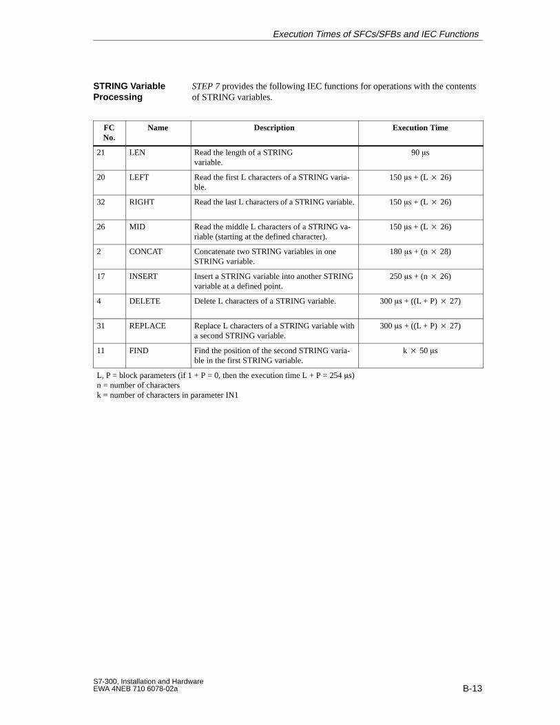
B-13S7-300, Installation and HardwareEWA 4NEB 710 6078-02a
STEP 7 provides the following IEC functions for operations with the contentsof STRING variables.
FCNo.
Name Description Execution Time
21 LEN Read the length of a STRING variable.
90 s
20 LEFT Read the first L characters of a STRING varia-ble.
150 s + (L 26)
32 RIGHT Read the last L characters of a STRING variable. 150 s + (L 26)
26 MID Read the middle L characters of a STRING va-riable (starting at the defined character).
150 s + (L 26)
2 CONCAT Concatenate two STRING variables in oneSTRING variable.
180 s + (n 28)
17 INSERT Insert a STRING variable into another STRINGvariable at a defined point.
250 s + (n 26)
4 DELETE Delete L characters of a STRING variable. 300 s + ((L + P) 27)
31 REPLACE Replace L characters of a STRING variable witha second STRING variable.
300 s + ((L + P) 27)
11 FIND Find the position of the second STRING varia-ble in the first STRING variable.
k 50 s
L, P = block parameters (if 1 + P = 0, then the execution time L + P = 254 s)n = number of charactersk = number of characters in parameter IN1
STRING VariableProcessing
Execution Times of SFCs/SFBs and IEC Functions
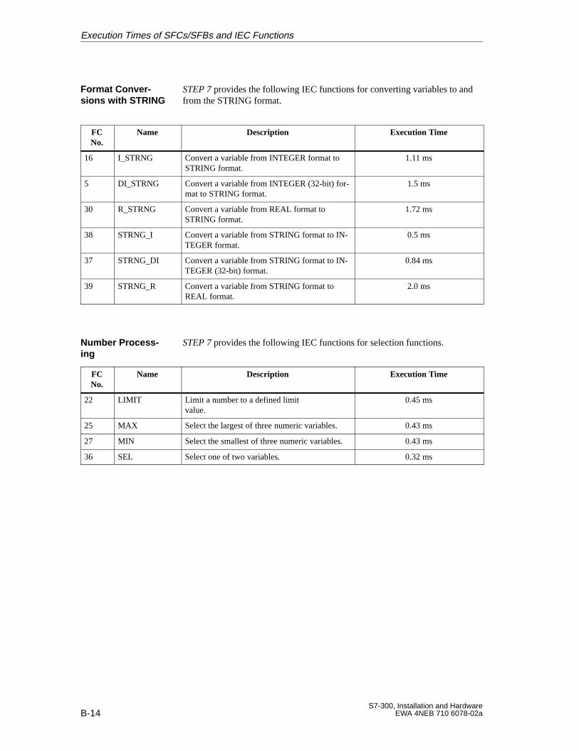
B-14S7-300, Installation and Hardware
EWA 4NEB 710 6078-02a
STEP 7 provides the following IEC functions for converting variables to andfrom the STRING format.
FCNo.
Name Description Execution Time
16 I_STRNG Convert a variable from INTEGER format toSTRING format.
1.11 ms
5 DI_STRNG Convert a variable from INTEGER (32-bit) for-mat to STRING format.
1.5 ms
30 R_STRNG Convert a variable from REAL format toSTRING format.
1.72 ms
38 STRNG_I Convert a variable from STRING format to IN-TEGER format.
0.5 ms
37 STRNG_DI Convert a variable from STRING format to IN-TEGER (32-bit) format.
0.84 ms
39 STRNG_R Convert a variable from STRING format toREAL format.
2.0 ms
STEP 7 provides the following IEC functions for selection functions.
FCNo.
Name Description Execution Time
22 LIMIT Limit a number to a defined limit value.
0.45 ms
25 MAX Select the largest of three numeric variables. 0.43 ms
27 MIN Select the smallest of three numeric variables. 0.43 ms
36 SEL Select one of two variables. 0.32 ms
Format Conver -sions with STRING
Number Process -ing
Execution Times of SFCs/SFBs and IEC Functions
C-1S7-300, Installation and HardwareEWA 4NEB 710 6078-02a
System Status List in the CPUs
The CPU is able to provide you, the S7-300 user, with certain information.The CPU stores this information in the “System status list”.
This appendix contains the sublists of the system status list provided by theCPU 312 IFM, 313, 314, 314 IFM, 315, 315-2 DP and 316.
The system status list contains data describing the current status of anS7-300. You can use it to gain an overview of the following at any time:
The S7-300 configuration
The current parameterization of the CPU and the parameterizable signalmodules
The current statuses and sequences in the CPU and the parameterizablesignal modules.
See the System and Standard Functions Reference Manual for a detailed de-scription of the structure of the system status list and all possible entries.
You can use SFC 51 “RDSYSST” from the user program to read out the en-tries in the system status list (see the System and Standard Functions Refer-ence Manual).
The system status list is divided into sublists. This makes it possible to targetspecific information in the system status list.
Each sublist contains:
Header information of four data words
A specific number of records containing the event information
Introduction
Definition
Reading the System Status List
Sublists
Structure of theSublists
C
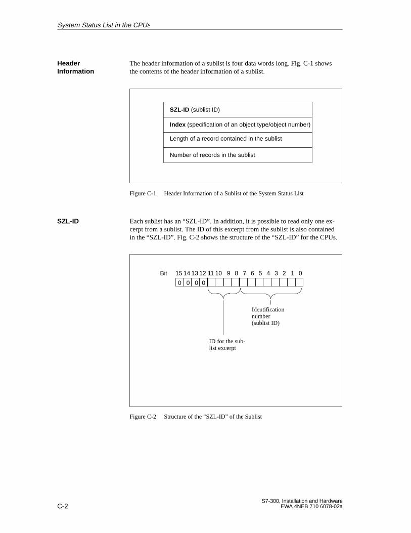
C-2S7-300, Installation and Hardware
EWA 4NEB 710 6078-02a
The header information of a sublist is four data words long. Fig. C-1 showsthe contents of the header information of a sublist.
SZL-ID (sublist ID)
Index (specification of an object type/object number)
Length of a record contained in the sublist
Number of records in the sublist
Figure C-1 Header Information of a Sublist of the System Status List
Each sublist has an “SZL-ID”. In addition, it is possible to read only one ex-cerpt from a sublist. The ID of this excerpt from the sublist is also containedin the “SZL-ID”. Fig. C-2 shows the structure of the “SZL-ID” for the CPUs.
101112131415 89Bit 234567 01
Identification number (sublist ID)
ID for the sub-list excerpt
0 00 0
Figure C-2 Structure of the “SZL-ID” of the Sublist
Header Information
SZL-ID
System Status List in the CPUs
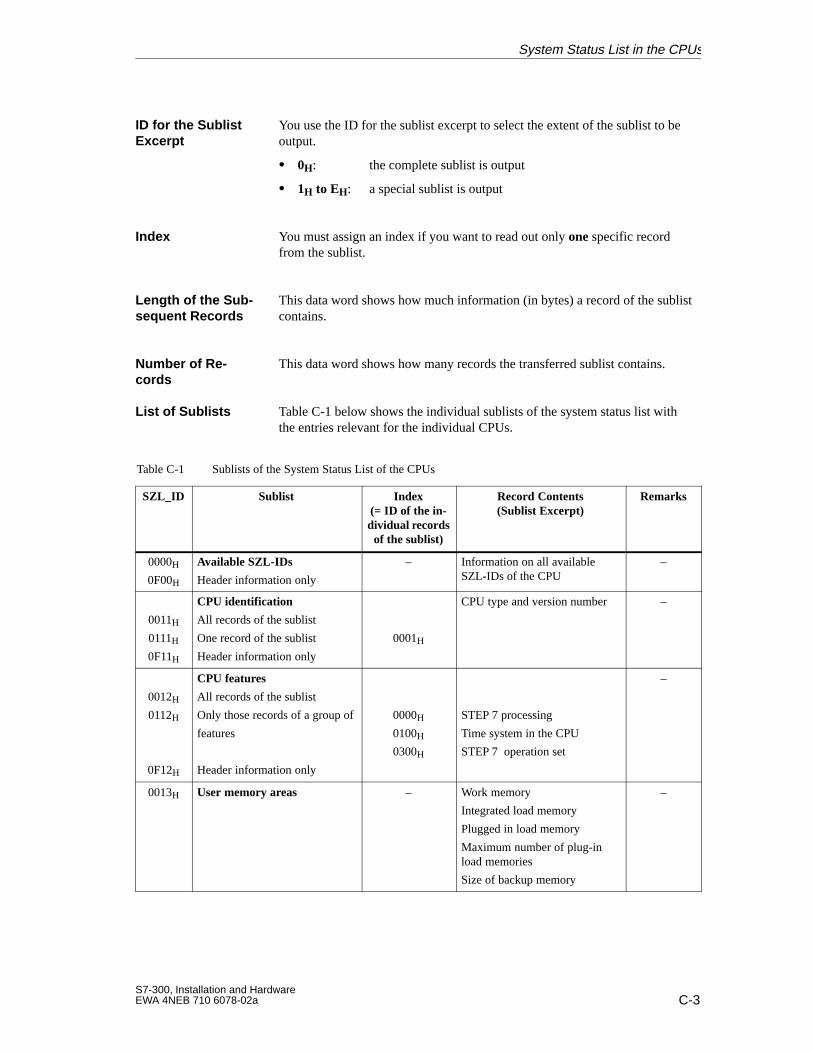
C-3S7-300, Installation and HardwareEWA 4NEB 710 6078-02a
You use the ID for the sublist excerpt to select the extent of the sublist to beoutput.
0H: the complete sublist is output
1H to EH: a special sublist is output
You must assign an index if you want to read out only one specific recordfrom the sublist.
This data word shows how much information (in bytes) a record of the sublistcontains.
This data word shows how many records the transferred sublist contains.
Table C-1 below shows the individual sublists of the system status list withthe entries relevant for the individual CPUs.
Table C-1 Sublists of the System Status List of the CPUs
SZL_ID Sublist Index(= ID of the in-dividual recordsof the sublist)
Record Contents(Sublist Excerpt)
Remarks
0000H
0F00H
Available SZL-IDs
Header information only
– Information on all availableSZL-IDs of the CPU
–
0011H0111H0F11H
CPU identification
All records of the sublist
One record of the sublist
Header information only
0001H
CPU type and version number –
0012H
0112H
0F12H
CPU features
All records of the sublist
Only those records of a group of
features
Header information only
0000H
0100H
0300H
STEP 7 processing
Time system in the CPU
STEP 7 operation set
–
0013H User memory areas – Work memory
Integrated load memory
Plugged in load memory
Maximum number of plug-inload memories
Size of backup memory
–
ID for the SublistExcerpt
Index
Length of the Sub-sequent Records
Number of Re -cords
List of Sublists
System Status List in the CPUs
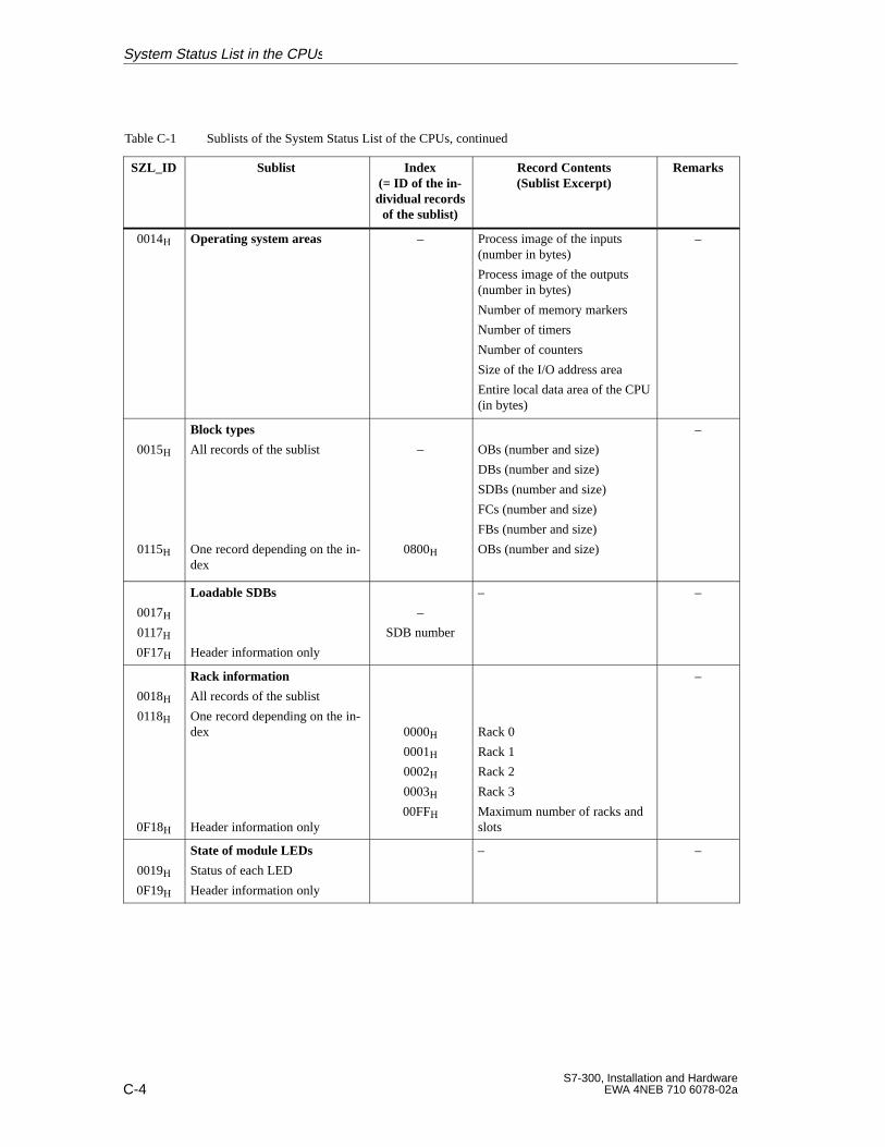
C-4S7-300, Installation and Hardware
EWA 4NEB 710 6078-02a
Table C-1 Sublists of the System Status List of the CPUs, continued
SZL_ID RemarksRecord Contents(Sublist Excerpt)
Index(= ID of the in-dividual recordsof the sublist)
Sublist
0014H Operating system areas – Process image of the inputs(number in bytes)
Process image of the outputs(number in bytes)
Number of memory markers
Number of timers
Number of counters
Size of the I/O address area
Entire local data area of the CPU(in bytes)
–
0015H
0115H
Block types
All records of the sublist
One record depending on the in-dex
–
0800H
OBs (number and size)
DBs (number and size)
SDBs (number and size)
FCs (number and size)
FBs (number and size)
OBs (number and size)
–
0017H
0117H0F17H
Loadable SDBs
Header information only
–
SDB number
– –
0018H
0118H
0F18H
Rack information
All records of the sublist
One record depending on the in-dex
Header information only
0000H
0001H
0002H
0003H
00FFH
Rack 0
Rack 1
Rack 2
Rack 3
Maximum number of racks andslots
–
0019H
0F19H
State of module LEDs
Status of each LED
Header information only
– –
System Status List in the CPUs
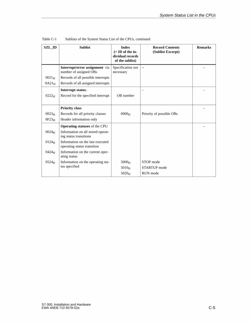
C-5S7-300, Installation and HardwareEWA 4NEB 710 6078-02a
Table C-1 Sublists of the System Status List of the CPUs, continued
SZL_ID RemarksRecord Contents(Sublist Excerpt)
Index(= ID of the in-dividual recordsof the sublist)
Sublist
0021H
0A21H
Interrupt/error assignment vianumber of assigned OBs
Records of all possible interrupts
Records of all assigned interrupts
Specification notnecessary
– –
0222H
Interrupt status ;
Record for the specified interrupt OB number
– –
0023H
0F23H
Priority class
Records for all priority classes
Header information only
0000H Priority of possible OBs
–
0024H
0124H
0424H
0524H
Operating statuses of the CPU
Information on all stored operat-ing status transitions
Information on the last executedoperating status transition
Information on the current oper-ating status
Information on the operating sta-tus specified
5000H
5010H
5020H
STOP mode
STARTUP mode
RUN mode
–
System Status List in the CPUs
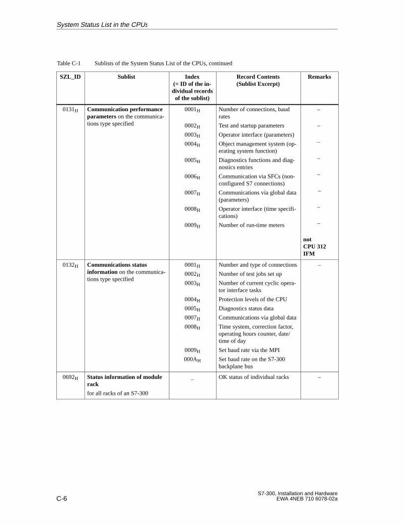
C-6S7-300, Installation and Hardware
EWA 4NEB 710 6078-02a
Table C-1 Sublists of the System Status List of the CPUs, continued
SZL_ID RemarksRecord Contents(Sublist Excerpt)
Index(= ID of the in-dividual recordsof the sublist)
Sublist
0131H Communication performanceparameters on the communica-tions type specified
0001H
0002H
0003H
0004H
0005H
0006H
0007H
0008H
0009H
Number of connections, baudrates
Test and startup parameters
Operator interface (parameters)
Object management system (op-erating system function)
Diagnostics functions and diag-nostics entries
Communication via SFCs (non-configured S7 connections)
Communications via global data(parameters)
Operator interface (time specifi-cations)
Number of run-time meters
–
–
–
–
–
–
–
–
notCPU 312IFM
0132H Communications status information on the communica-tions type specified
0001H
0002H
0003H
0004H
0005H
0007H
0008H
0009H
000AH
Number and type of connections
Number of test jobs set up
Number of current cyclic opera-tor interface tasks
Protection levels of the CPU
Diagnostics status data
Communications via global data
Time system, correction factor,operating hours counter, date/time of day
Set baud rate via the MPI
Set baud rate on the S7-300backplane bus
–
0692H Status information of modulerack
for all racks of an S7-300
_ OK status of individual racks –
System Status List in the CPUs
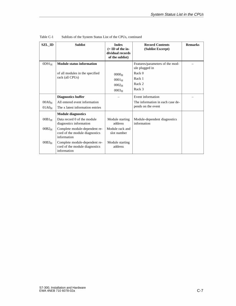
C-7S7-300, Installation and HardwareEWA 4NEB 710 6078-02a
Table C-1 Sublists of the System Status List of the CPUs, continued
SZL_ID RemarksRecord Contents(Sublist Excerpt)
Index(= ID of the in-dividual recordsof the sublist)
Sublist
0D91H Module status information
of all modules in the specifiedrack (all CPUs)
0000H
0001H
0002H
0003H
Features/parameters of the mod-ule plugged in
Rack 0
Rack 1
Rack 2
Rack 3
–
00A0H
01A0H
Diagnostics buffer
All entered event information
The x latest information entries
– Event information
The information in each case de-pends on the event
–
00B1H
00B2H
00B3H
Module diagnostics
Data record 0 of the modulediagnostics information
Complete module-dependent re-cord of the module diagnosticsinformation
Complete module-dependent re-cord of the module diagnosticsinformation
Module startingaddress
Module rack andslot number
Module startingaddress
Module-dependent diagnosticsinformation
System Status List in the CPUs
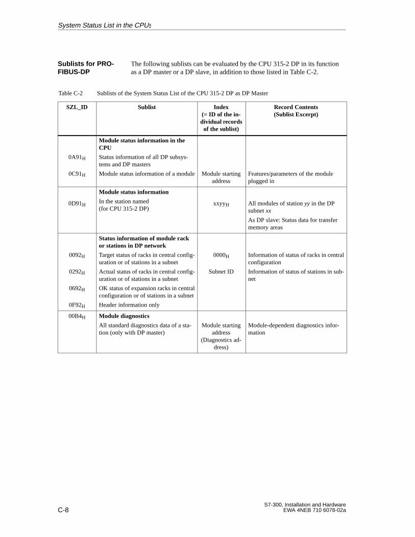
C-8S7-300, Installation and Hardware
EWA 4NEB 710 6078-02a
The following sublists can be evaluated by the CPU 315-2 DP in its functionas a DP master or a DP slave, in addition to those listed in Table C-2.
Table C-2 Sublists of the System Status List of the CPU 315-2 DP as DP Master
SZL_ID Sublist Index(= ID of the in-dividual recordsof the sublist)
Record Contents(Sublist Excerpt)
0A91H
0C91H
Module status information in theCPU
Status information of all DP subsys-tems and DP masters
Module status information of a module
Module startingaddress
Features/parameters of the moduleplugged in
0D91H
Module status information
In the station named (for CPU 315-2 DP)
xxyyH All modules of station yy in the DPsubnet xx
As DP slave: Status data for transfermemory areas
0092H
0292H
0692H
0F92H
Status information of module rackor stations in DP network
Target status of racks in central config-uration or of stations in a subnet
Actual status of racks in central config-uration or of stations in a subnet
OK status of expansion racks in centralconfiguration or of stations in a subnet
Header information only
0000H
Subnet ID
Information of status of racks in centralconfiguration
Information of status of stations in sub-net
00B4H Module diagnostics
All standard diagnostics data of a sta-tion (only with DP master)
Module startingaddress
(Diagnostics ad-dress)
Module-dependent diagnostics infor-mation
Sublists for PRO -FIBUS-DP
System Status List in the CPUs
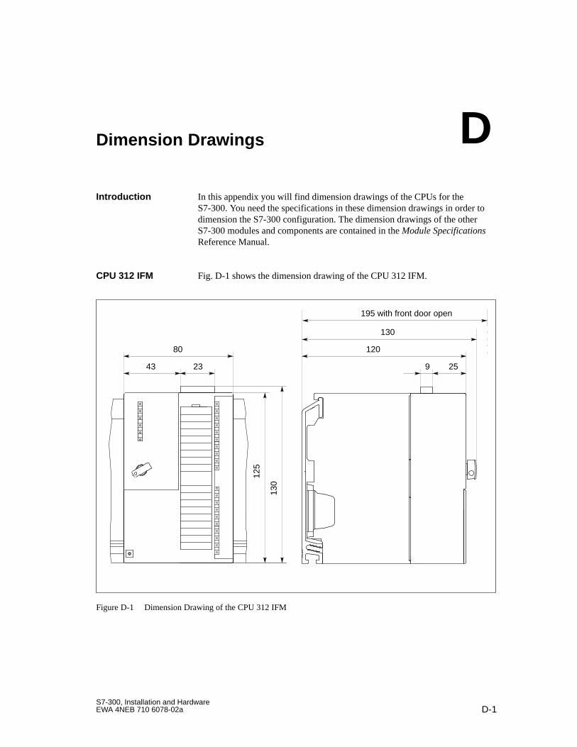
D-1S7-300, Installation and HardwareEWA 4NEB 710 6078-02a
Dimension Drawings
In this appendix you will find dimension drawings of the CPUs for theS7-300. You need the specifications in these dimension drawings in order todimension the S7-300 configuration. The dimension drawings of the otherS7-300 modules and components are contained in the Module SpecificationsReference Manual.
Fig. D-1 shows the dimension drawing of the CPU 312 IFM.
130
12080
43 23
125
130
9 25
195 with front door open
Figure D-1 Dimension Drawing of the CPU 312 IFM
Introduction
CPU 312 IFM
D
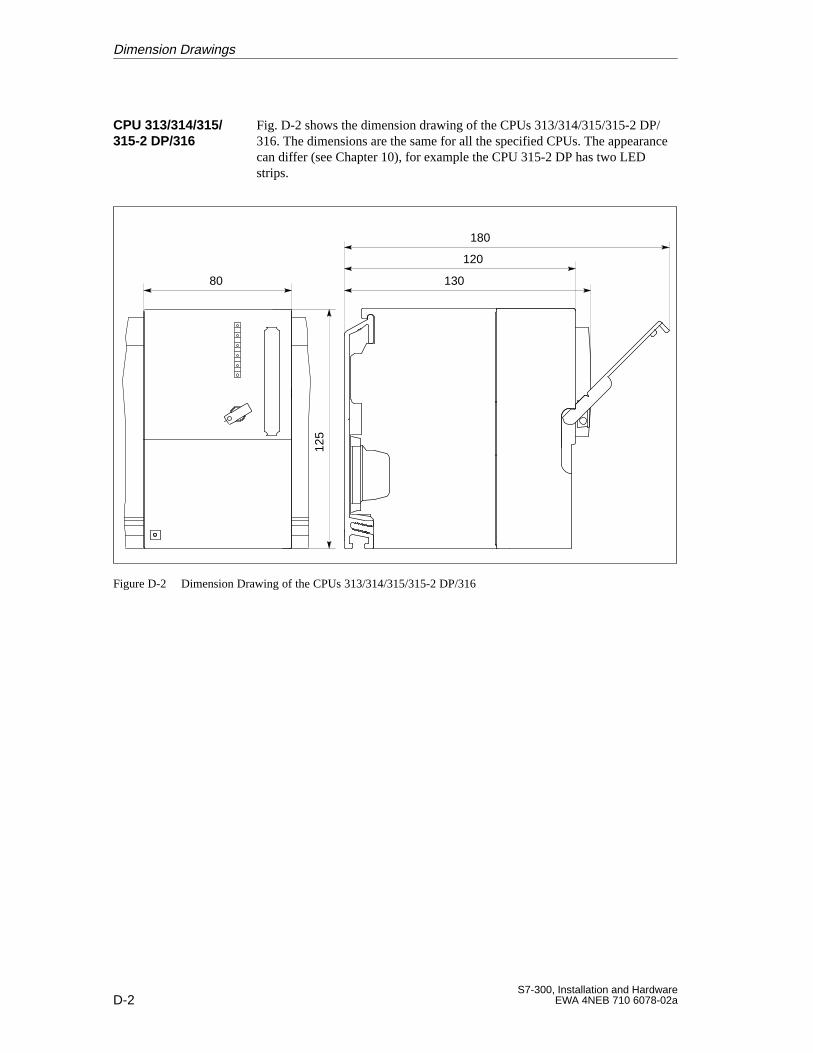
D-2S7-300, Installation and Hardware
EWA 4NEB 710 6078-02a
Fig. D-2 shows the dimension drawing of the CPUs 313/314/315/315-2 DP/316. The dimensions are the same for all the specified CPUs. The appearancecan differ (see Chapter 10), for example the CPU 315-2 DP has two LEDstrips.
125
130
120
180
80
Figure D-2 Dimension Drawing of the CPUs 313/314/315/315-2 DP/316
CPU 313/314/315/315-2 DP/316
Dimension Drawings
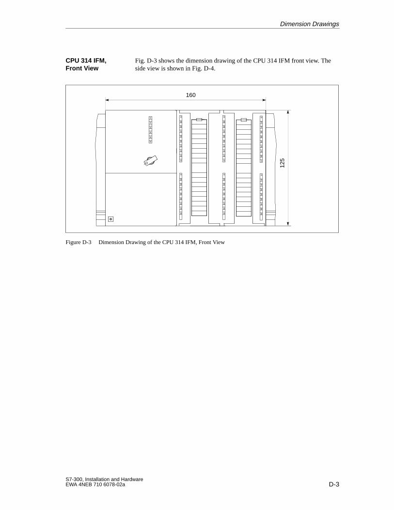
D-3S7-300, Installation and HardwareEWA 4NEB 710 6078-02a
Fig. D-3 shows the dimension drawing of the CPU 314 IFM front view. Theside view is shown in Fig. D-4.
125
160
Figure D-3 Dimension Drawing of the CPU 314 IFM, Front View
CPU 314 IFM,Front V iew
Dimension Drawings
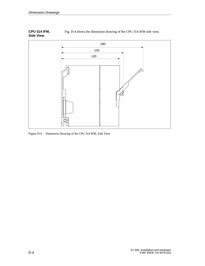
D-4S7-300, Installation and Hardware
EWA 4NEB 710 6078-02a
Fig. D-4 shows the dimension drawing of the CPU 314 IFM side view.
130
120
180
Figure D-4 Dimension Drawing of the CPU 314 IFM, Side View
CPU 314 IFM, Side View
Dimension Drawings
E-1S7-300, Installation and HardwareEWA 4NEB 710 6078-02a
Guidelines for Handling ElectrostaticSensitive Devices (ESD)
In this appendix, we explain
what is meant by “electrostatic sensitive devices”
the precautions you must observe when handling and working with elec-trostatic sensitive devices.
This chapter contains the following sections on electrostatic sensitive de-vices:
Section Contents Page
E.1 What is ESD? E-2
E.2 Electrostatic charging of persons E-3
E.3 General protective measures against electrostatic dischargedamage
E-4
Introduction
In this Chapter
E
E-2S7-300, Installation and Hardware
EWA 4NEB 710 6078-02a
E.1 What is ESD?
All electronic modules are equipped with large-scale integrated ICs or com-ponents. Due to their design, these electronic elements are very sensitive toovervoltages and thus to any electrostatic discharge.
These Electrostatic Sensitive Devices are commonly referred to by the ab-breviation ESD.
Electrostatic sensitive devices are labelled with the following symbol:
!Caution
Electrostatic sensitive devices are subject to voltages that are far below thevoltage values that can still be perceived by human beings. These voltagesare present if you touch a component or the electrical connections of a mod-ule without previously being electrostatically discharged. In most cases, thedamage caused by an overvoltage is not immediately noticeable and resultsin total damage only after a prolonged period of operation.
Definition
Guidelines for Handling Electrostatic Sensitive Devices (ESD)
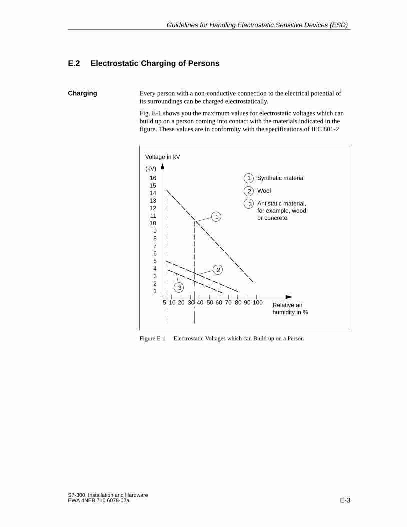
E-3S7-300, Installation and HardwareEWA 4NEB 710 6078-02a
E.2 Electrostatic Charging of Persons
Every person with a non-conductive connection to the electrical potential ofits surroundings can be charged electrostatically.
Fig. E-1 shows you the maximum values for electrostatic voltages which canbuild up on a person coming into contact with the materials indicated in thefigure. These values are in conformity with the specifications of IEC 801-2.
Voltage in kV
123456789
10111213141516
(kV)
5 10 20 30 40 50 60 70 80 90 100 Relative airhumidity in %
1
3
1 Synthetic material
2 Wool
3 Antistatic material,for example, woodor concrete
2
Figure E-1 Electrostatic Voltages which can Build up on a Person
Charging
Guidelines for Handling Electrostatic Sensitive Devices (ESD)
E-4S7-300, Installation and Hardware
EWA 4NEB 710 6078-02a
E.3 General Protective Measures against Electrostatic Discharge Dam-age
Make sure that the personnel, working surfaces and packaging are suffi-ciently grounded when handling electrostatic sensitive devices.You thus avoid electrostatic charging.
You should touch electrostatic sensitive devices only if it is unavoidable(for example, during maintenance work). Hold modules without touching thepins of components or printed conductors. In this way, the discharged energycannot affect the sensitive devices.
If you have to carry out measurements on a module, you must discharge yourbody before you start the measurement by touching grounded metallic parts.Use grounded measuring devices only.
Ensure SufficientGrounding
Avoid Direct Contact
Guidelines for Handling Electrostatic Sensitive Devices (ESD)
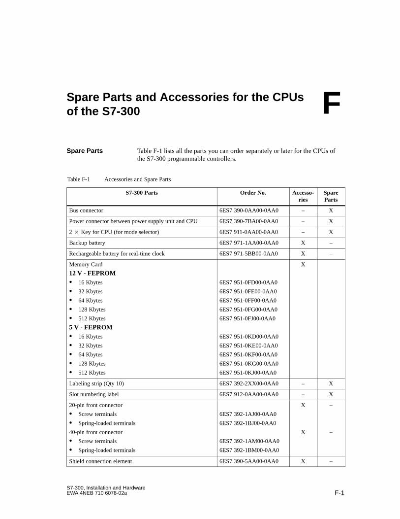
F-1S7-300, Installation and HardwareEWA 4NEB 710 6078-02a
Spare Parts and Accessories for the CPUsof the S7-300
Table F-1 lists all the parts you can order separately or later for the CPUs ofthe S7-300 programmable controllers.
Table F-1 Accessories and Spare Parts
S7-300 Parts Order No. Accesso-ries
SpareParts
Bus connector 6ES7 390-0AA00-0AA0 – X
Power connector between power supply unit and CPU 6ES7 390-7BA00-0AA0 – X
2 Key for CPU (for mode selector) 6ES7 911-0AA00-0AA0 – X
Backup battery 6ES7 971-1AA00-0AA0 X –
Rechargeable battery for real-time clock 6ES7 971-5BB00-0AA0 X –
Memory Card
12 V - FEPROM 16 Kbytes
32 Kbytes
64 Kbytes
128 Kbytes
512 Kbytes
5 V - FEPROM 16 Kbytes
32 Kbytes
64 Kbytes
128 Kbytes
512 Kbytes
6ES7 951-0FD00-0AA0
6ES7 951-0FE00-0AA0
6ES7 951-0FF00-0AA0
6ES7 951-0FG00-0AA0
6ES7 951-0FJ00-0AA0
6ES7 951-0KD00-0AA0
6ES7 951-0KE00-0AA0
6ES7 951-0KF00-0AA0
6ES7 951-0KG00-0AA0
6ES7 951-0KJ00-0AA0
X
Labeling strip (Qty 10) 6ES7 392-2XX00-0AA0 – X
Slot numbering label 6ES7 912-0AA00-0AA0 – X
20-pin front connector
Screw terminals
Spring-loaded terminals
40-pin front connector
Screw terminals
Spring-loaded terminals
6ES7 392-1AJ00-0AA0
6ES7 392-1BJ00-0AA0
6ES7 392-1AM00-0AA0
6ES7 392-1BM00-0AA0
X
X
–
–
Shield connection element 6ES7 390-5AA00-0AA0 X –
Spare Parts
F
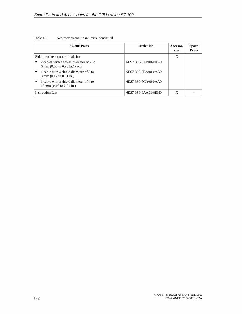
F-2S7-300, Installation and Hardware
EWA 4NEB 710 6078-02a
Table F-1 Accessories and Spare Parts, continued
S7-300 Parts SpareParts
Accesso-ries
Order No.
Shield connection terminals for
2 cables with a shield diameter of 2 to 6 mm (0.08 to 0.23 in.) each
1 cable with a shield diameter of 3 to 8 mm (0.12 to 0.31 in.)
1 cable with a shield diameter of 4 to 13 mm (0.16 to 0.51 in.)
6ES7 390-5AB00-0AA0
6ES7 390-5BA00-0AA0
6ES7 390-5CA00-0AA0
X –
Instruction List 6ES7 398-8AA01-8BN0 X –
Spare Parts and Accessories for the CPUs of the S7-300
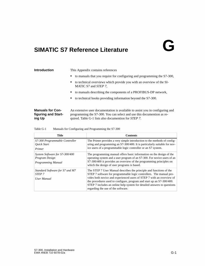
G-1S7-300, Installation and HardwareEWA 4NEB 710 6078-02a
SIMATIC S7 Reference Literature
This Appendix contains references
to manuals that you require for configuring and programming the S7-300,
to technical overviews which provide you with an overview of the SI-MATIC S7 and STEP 7,
to manuals describing the components of a PROFIBUS-DP network,
to technical books providing information beyond the S7-300.
An extensive user documentation is available to assist you in configuring andprogramming the S7-300. You can select and use this documention as re-quired. Table G-1 lists also documention for STEP 7.
Table G-1 Manuals for Configuring and Programming the S7-300
Title Contents
S7-300 Programmable ControllerQuick Start
Primer
The Primer provides a very simple introduction to the methods of config-uring and programming an S7-300/400. It is particularly suitable for nov-ice users of a programmable logic controller or an S7 system.
System Software for S7-300/400Program Design
Programming Manual
The programming manual offers basic information on the design of theoperating system and a user program of an S7-300. For novice users of anS7-300/400 it provides an overview of the programming principles onwhich the design of user programs is based.
Standard Software for S7 und M7STEP 7
User Manual
The STEP 7 User Manual describes the principle and functions of theSTEP 7 software for programmable logic controllers. The manual pro-vides both novice and experienced users of STEP 7 with an overview ofthe procedures used to configure, program and start up an S7-300/400.STEP 7 includes an online help system for detailed answers to questionsregarding the use of the software.
Introduction
Manuals for Con -figuring and Start -ing Up
G
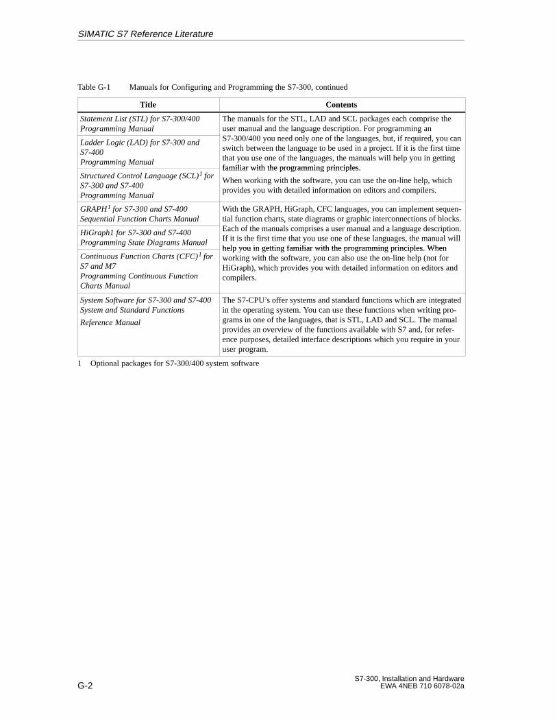
G-2S7-300, Installation and Hardware
EWA 4NEB 710 6078-02a
Table G-1 Manuals for Configuring and Programming the S7-300, continued
Title Contents
Statement List (STL) for S7-300/400Programming Manual
The manuals for the STL, LAD and SCL packages each comprise theuser manual and the language description. For programming anS7 300/400 d l f th l b t if i dLadder Logic (LAD) for S7-300 and
S7-400Programming Manual
g g p p g gS7-300/400 you need only one of the languages, but, if required, you canswitch between the language to be used in a project. If it is the first timethat you use one of the languages, the manuals will help you in gettingfamiliar with the programming principles
Structured Control Language (SCL)1 forS7-300 and S7-400Programming Manual
familiar with the programming principles.
When working with the software, you can use the on-line help, whichprovides you with detailed information on editors and compilers.
GRAPH1 for S7-300 and S7-400Sequential Function Charts Manual
With the GRAPH, HiGraph, CFC languages, you can implement sequen-tial function charts, state diagrams or graphic interconnections of blocks.E h f th l i l d l d i tiHiGraph1 for S7-300 and S7-400
Programming State Diagrams Manual
, g g pEach of the manuals comprises a user manual and a language description.If it is the first time that you use one of these languages, the manual willhelp you in getting familiar with the programming principles. When
Continuous Function Charts (CFC)1 forS7 and M7Programming Continuous FunctionCharts Manual
help you in getting famili ar with the programming principles. Whenworking with the software, you can also use the on-line help (not forHiGraph), which provides you with detailed information on editors andcompilers.
System Software for S7-300 and S7-400System and Standard Functions
Reference Manual
The S7-CPU’s offer systems and standard functions which are integratedin the operating system. You can use these functions when writing pro-grams in one of the languages, that is STL, LAD and SCL. The manualprovides an overview of the functions available with S7 and, for refer-ence purposes, detailed interface descriptions which you require in youruser program.
1 Optional packages for S7-300/400 system software
SIMATIC S7 Reference Literature
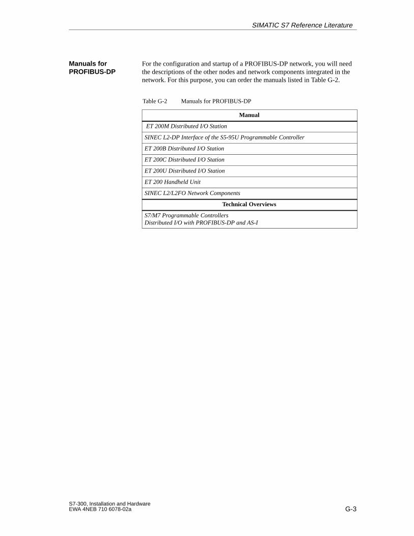
G-3S7-300, Installation and HardwareEWA 4NEB 710 6078-02a
For the configuration and startup of a PROFIBUS-DP network, you will needthe descriptions of the other nodes and network components integrated in thenetwork. For this purpose, you can order the manuals listed in Table G-2.
Table G-2 Manuals for PROFIBUS-DP
Manual
ET 200M Distributed I/O Station
SINEC L2-DP Interface of the S5-95U Programmable Controller
ET 200B Distributed I/O Station
ET 200C Distributed I/O Station
ET 200U Distributed I/O Station
ET 200 Handheld Unit
SINEC L2/L2FO Network Components
Technical Overviews
S7/M7 Programmable ControllersDistributed I/O with PROFIBUS-DP and AS-I
Manuals forPROFIBUS-DP
SIMATIC S7 Reference Literature

G-4S7-300, Installation and Hardware
EWA 4NEB 710 6078-02a
SIMATIC S7 Reference Literature
H-1S7-300, Installation and HardwareEWA 4NEB 710 6078-02a
Safety of Electronic Control Equipment
The information provided here is of a predominantly fundamental nature andapplies regardless of the type of electronic control system and its manufac-turer.
Maximum reliability of the SIMATIC systems and components is achievedby implementing the following extensive and cost-effective measures duringthe development and manufacture:
Use of high-quality components;
Worst-case design of all circuits;
Systematic and computer-controlled testing of all components supplied bysubcontractors;
Burn-in of all LSI circuits (e.g. processors, memories, etc.);
Measures to prevent static charge building up when handling MOS ICs;
Visual checks at different stages of manufacture;
Continuous heat-run test at elevated ambient temperature over a period ofseveral days;
Careful computer-controlled final testing;
Statistical evaluation of all faulty systems and components to enable theimmediate initiation of suitable corrective measures;
Monitoring of the most important control components using on-line tests(watchdog for the CPU, etc.).
These measures are basic measures. They prevent or rectify a large propor-tion of possible faults.
Introduction
Reliability
H
H-2S7-300, Installation and Hardware
EWA 4NEB 710 6078-02a
In all cases where the occurrence of failures can result in material damage orinjury to persons, special measures must be taken to enhance the safety of theinstallation – and therefore also of the situation. For this type of application,relevant, plant-specific regulations exist that must be observed on installingthe control systems (e.g. VDE 0116 for burner control systems).
For electronic control equipment with a safety function, the measures thathave to be taken to prevent or rectify faults are based on the risks involved inthe installation. Above a certain potential danger, the basic measures listedabove are no longer sufficient. In such cases, additional measures (e.g. redun-dant configurations, tests, etc.) must be implemented for the control equip-ment and certified (DIN VDE 0801). The S5-95F fail-safe programmablecontroller has been prototype tested by the German Technical Inspectorate,BIA and GEM III and several certificates have been granted. It is, therefore,just as able as the S5-115F fail-safe PLC that has already been tested to con-trol and monitor safety-related areas of the installation.
In almost every installation there are sections that perform safety-relatedtasks (e.g. Emergency Stop pushbuttons, protective guards, two-hand-oper-ated switches). To avoid the need to observe the entire control equipmentfrom the safety aspect, the control equipment is usually divided into a safety-related and non-safety-related area. In the non-safety-related area, no spe-cial demands are placed on the safety of the control equipment because anyfailure in the electronics will have no effect on the safety of the installation.In the safety-related area, however, the only control systems and switchgearthat are permitted to be used are those that comply with the relevant regula-tions.
The following divisions are common in practical situations:
1. For control equipment with few safety-related functions (e.g. machinecontrols)
The conventional PLC is responsible for machine control and the safety-related functions are implemented with the fail-safe S5-95F mini PLC.
2. For control equipment with a medium degree of safety-related functional-ity (e.g. chemical installations, cable cars)
The non-safety-related area is also implemented here with a conventionalPLC and the safety-related area is implemented with a tested fail-safePLC (S5-115F or several S5-95Fs).
The entire installation is implemented with a fail-safe control system.
3. For control equipment with mainly safety-related functions (e.g. burnercontrol systems)
The entire control system is implemented with fail-safe technology.
The Risks
Division Into Safe -ty-Related andNon-Safety-Related Areas
Safety of Electronic Control Equipment

H-3S7-300, Installation and HardwareEWA 4NEB 710 6078-02a
Even when electronic control equipment has been configured for maximumdesign safety, for example using multi-channel setups, it is still of the utmostimportance that the instructions given in the operating manual are followedexactly. Incorrect handling can render measures intended to prevent danger-ous faults ineffective, or generate additional sources of danger.
Important Note
Safety of Electronic Control Equipment

H-4S7-300, Installation and Hardware
EWA 4NEB 710 6078-02a
Safety of Electronic Control Equipment

I-1S7-300, Installation and HardwareEWA 4NEB 710 6078-02a
Siemens Worldwide
In this appendix you will find a list of
locations of Siemens offices in Germany and
all European and non–European offices and representatives ofSiemens AG.
The following table lists all Siemens offices in Germany.
Aachen
Augsburg
Bayreuth
Berlin
Bielefeld
Bonn
Braunschweig
Bremen
Chemnitz
Darmstadt
Dortmund
Dresden
Duisburg
Düsseldorf
Erfurt
Essen
Frankfurt a.M.
Freiburg
Hamburg
Heilbronn
Karlsruhe
Kassel
Kempten/Allg.
Kiel
Koblenz
Cologne
Constance
Laatzen
Leipzig
Lingen
Magdeburg
Mainz
Mannheim
Munich
Münster/Westf.
Nuremberg
Osnabrück
Regensburg
Rostock
Saarbrücken
Siegen
Stuttgart
Ulm
Wetzlar
Wilhelmshaven
Wuppertal
Würzburg
In this Appendix
Siemens Offices inGermany
I

I-2S7-300, Installation and Hardware
EWA 4NEB 710 6078-02a
The following table lists all European Siemens offices and representatives.
Austria
Siemens AG Austria
Bregenz
Graz
Innsbruck
Linz
Salzburg
Vienna
Belgium
Siemens S.A.
Brussels
Liège
Siemens N. V.
Antwerp
Bosnia-Hercegovina
Generalexport Predstavnistvo Sarajevo
Sarajevo
Bulgaria
Siemens AG, Representative in Bulgaria
Sofia
Croatia
Siemens d. o. o.
Zagreb
Cyprus
GEVO Ltd.
or
Jolali Ltd.
Nicosia
Czech Republic
Siemens AG
Brno
Mladá Boleslav
Prague
Denmark
Siemens A/S
Copenhagen, Ballerup
Finland
Siemens Oy
Espoo, Helsinki
France
Siemens S.A.
Haguenau
Lille, Seclin
Lyon, Caluire-et-Cuire
Marseille
Metz
Paris, Saint-Denis
Strasbourg
Toulouse
Great Britain
Siemens plc
Birmingham, Walsall
Bristol, Clevedon
Congleton
Edinburgh
Glasgow
Leeds
Liverpool
London, Sunbury-on-Thames
Manchester
Newcastle
Greece
Siemens A.E.
Athens, Amaroussio
Thessaloniki
Hungary
Siemens Kft
Budapest
Iceland
Smith & Norland H/F
Reykjavik
Ireland
Siemens Ltd.
Dublin
European Compa -nies and Repre -sentatives
Siemens Worldwide
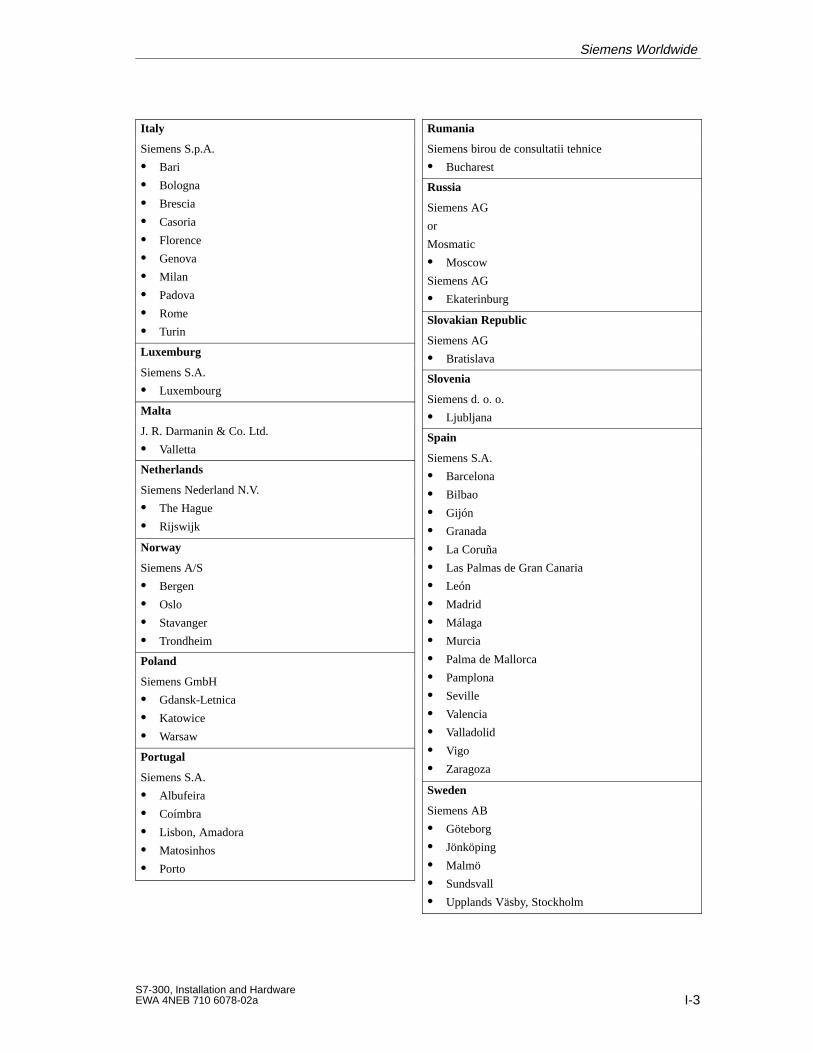
I-3S7-300, Installation and HardwareEWA 4NEB 710 6078-02a
Italy
Siemens S.p.A.
Bari
Bologna
Brescia
Casoria
Florence
Genova
Milan
Padova
Rome
Turin
Luxemburg
Siemens S.A.
Luxembourg
Malta
J. R. Darmanin & Co. Ltd.
Valletta
Netherlands
Siemens Nederland N.V.
The Hague
Rijswijk
Norway
Siemens A/S
Bergen
Oslo
Stavanger
Trondheim
Poland
Siemens GmbH
Gdansk-Letnica
Katowice
Warsaw
Portugal
Siemens S.A.
Albufeira
Coímbra
Lisbon, Amadora
Matosinhos
Porto
Rumania
Siemens birou de consultatii tehnice
Bucharest
Russia
Siemens AG
or
Mosmatic
Moscow
Siemens AG
Ekaterinburg
Slovakian Republic
Siemens AG
Bratislava
Slovenia
Siemens d. o. o.
Ljubljana
Spain
Siemens S.A.
Barcelona
Bilbao
Gijón
Granada
La Coruña
Las Palmas de Gran Canaria
León
Madrid
Málaga
Murcia
Palma de Mallorca
Pamplona
Seville
Valencia
Valladolid
Vigo
Zaragoza
Sweden
Siemens AB
Göteborg
Jönköping
Malmö
Sundsvall
Upplands Väsby, Stockholm
Siemens Worldwide

I-4S7-300, Installation and Hardware
EWA 4NEB 710 6078-02a
Switzerland
Siemens-Albis AG
Basle
Berne
Zürich
Siemens-Albis S.A.
Renens, Lausanne
Turkey
SIMKO
Adana
Ankara
Bursa
Istanbul
Izmir
Samsun
Ukraine
Siemens AG
Kiev
The following table lists all non–European Siemens offices and representa-tives.
The following table lists all Siemens offices and representatives in Africa.
Algeria
Siemens Bureau d’Alger
Alger
Angola
TECNIDATA
Luanda
Bophuthatswana
Siemens Ltd.
Mafekeng
Egypt
Siemens Technical Office
Cairo-Mohandessin
Siemens Technical Office
Alexandria
EGEMAC S.A.E.
Cairo-Mattaria
Ethopia
Addis Electrical Engineering Ltd.
Addis Abeba
Ivory Coast
Siemens AG
Abidjan
Libya
Siemens AG, Branch Libya
Tripoli
Morocco
SETEL
Société Electrotechnique et de Télécommunications S.A.
Casablanca
Moçambique
Siemens Liaison Office
Maputo
Namibia
Siemens (Pty.) Ltd.
Windhoek
Nigeria
Electro Technologies Nigeria Ltd. (ELTEC)
Lagos
Rwanda
Etablissement Rwandais
Kigali
Non-EuropeanCompanies andRepresentatives
Africa
Siemens Worldwide

I-5S7-300, Installation and HardwareEWA 4NEB 710 6078-02a
South Africa
Siemens Ltd.
Cape Town
Durban
Johannesburg
Middelburg
Newcastle
Port Elizabeth
Pretoria
Sudan
National Electrical & Commercial Company (NECC)
Khartoum
Swaziland
Siemens (Pty.) Ltd.
Mbabane
Tanzania
Tanzania Electrical Services Ltd.
Dar-es-Salaam
Tunisia
Sitelec S.A.
Tunis
Zaire
SOFAMATEL S.P.R.L.
Kinshasa
Zambia
Electrical Maintenance Lusaka Ltd.
Lusaka
Zimbabwe
Electro Technologies Corporation (Pvt.) Ltd. (ETC)
Harare
The following table lists all Siemens offices and representatives in America.
Argentina
Siemens S.A.
Bahía Blanca
Buenos Aires
Còrdoba
Mendoza
Rosario
Bolivia
Sociedad Comercial é Industrial Hansa Ltda.
La Paz
Brazil
Siemens S.A.
Belém
Belo Horizonte
Brasilia
Campinas
Curitiba
Fortaleza
Pôrto Alegre
Recife
Rio de Janeiro
Salvador de Bahia
São Paulo
Vitória
Canada
Siemens Electric Ltd.
Montreal, Québec
Toronto
Chile
INGELSAC
Santiago de Chile
Columbia
Siemens S.A.
Barranquilla
Bogotá
Cali
Medellín
Costa Rica
Siemens S.A.
Panama
San José
Cuba
Respresentación
Consult iva EUMEDA
La Habana
Ecuador
Siemens S.A.
Quito
America
Siemens Worldwide
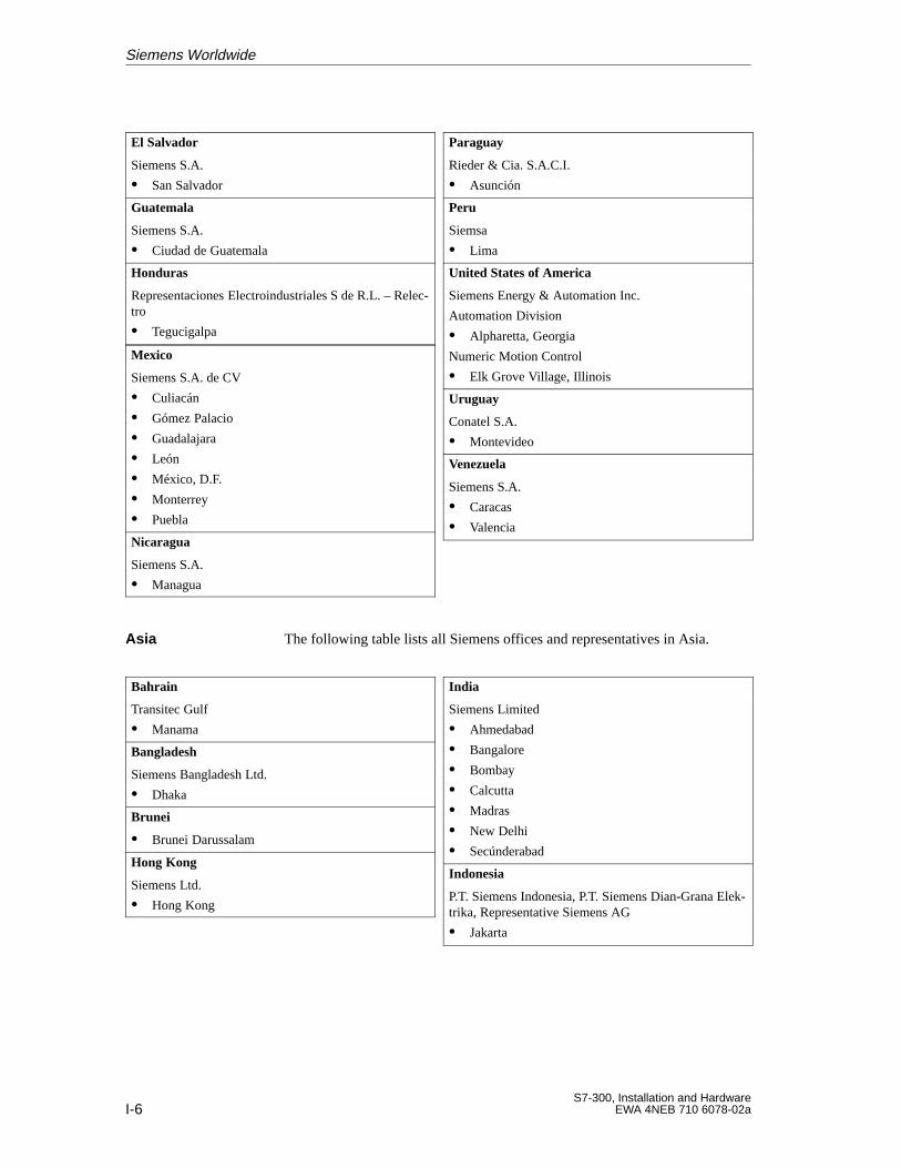
I-6S7-300, Installation and Hardware
EWA 4NEB 710 6078-02a
El Salvador
Siemens S.A.
San Salvador
Guatemala
Siemens S.A.
Ciudad de Guatemala
Honduras
Representaciones Electroindustriales S de R.L. – Relec-tro
Tegucigalpa
Mexico
Siemens S.A. de CV
Culiacán
Gómez Palacio
Guadalajara
León
México, D.F.
Monterrey
Puebla
Nicaragua
Siemens S.A.
Managua
Paraguay
Rieder & Cia. S.A.C.I.
Asunción
Peru
Siemsa
Lima
United States of America
Siemens Energy & Automation Inc.
Automation Division
Alpharetta, Georgia
Numeric Motion Control
Elk Grove Village, Illinois
Uruguay
Conatel S.A.
Montevideo
Venezuela
Siemens S.A.
Caracas
Valencia
The following table lists all Siemens offices and representatives in Asia.
Bahrain
Transitec Gulf
Manama
Bangladesh
Siemens Bangladesh Ltd.
Dhaka
Brunei
Brunei Darussalam
Hong Kong
Siemens Ltd.
Hong Kong
India
Siemens Limited
Ahmedabad
Bangalore
Bombay
Calcutta
Madras
New Delhi
Secúnderabad
Indonesia
P.T. Siemens Indonesia, P.T. Siemens Dian-Grana Elek-trika, Representative Siemens AG
Jakarta
Asia
Siemens Worldwide
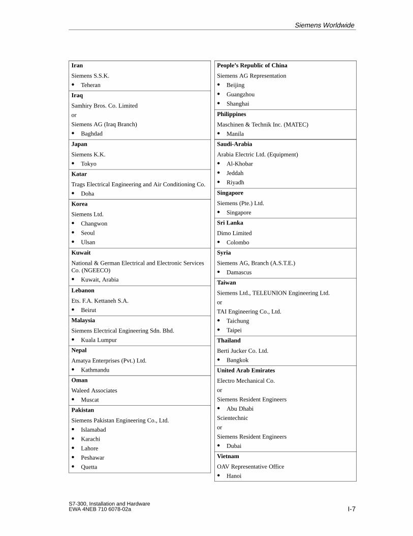
I-7S7-300, Installation and HardwareEWA 4NEB 710 6078-02a
Iran
Siemens S.S.K.
Teheran
Iraq
Samhiry Bros. Co. Limited
or
Siemens AG (Iraq Branch)
Baghdad
Japan
Siemens K.K.
Tokyo
Katar
Trags Electrical Engineering and Air Conditioning Co.
Doha
Korea
Siemens Ltd.
Changwon
Seoul
Ulsan
Kuwait
National & German Electrical and Electronic ServicesCo. (NGEECO)
Kuwait, Arabia
Lebanon
Ets. F.A. Kettaneh S.A.
Beirut
Malaysia
Siemens Electrical Engineering Sdn. Bhd.
Kuala Lumpur
Nepal
Amatya Enterprises (Pvt.) Ltd.
Kathmandu
Oman
Waleed Associates
Muscat
Pakistan
Siemens Pakistan Engineering Co., Ltd.
Islamabad
Karachi
Lahore
Peshawar
Quetta
People’s Republic of China
Siemens AG Representation
Beijing
Guangzhou
Shanghai
Philippines
Maschinen & Technik Inc. (MATEC)
Manila
Saudi-Arabia
Arabia Electric Ltd. (Equipment)
Al-Khobar
Jeddah
Riyadh
Singapore
Siemens (Pte.) Ltd.
Singapore
Sri Lanka
Dimo Limited
Colombo
Syria
Siemens AG, Branch (A.S.T.E.)
Damascus
Taiwan
Siemens Ltd., TELEUNION Engineering Ltd.
or
TAI Engineering Co., Ltd.
Taichung
Taipei
Thailand
Berti Jucker Co. Ltd.
Bangkok
United Arab Emirates
Electro Mechanical Co.
or
Siemens Resident Engineers
Abu Dhabi
Scientechnic
or
Siemens Resident Engineers
Dubai
Vietnam
OAV Representative Office
Hanoi
Siemens Worldwide
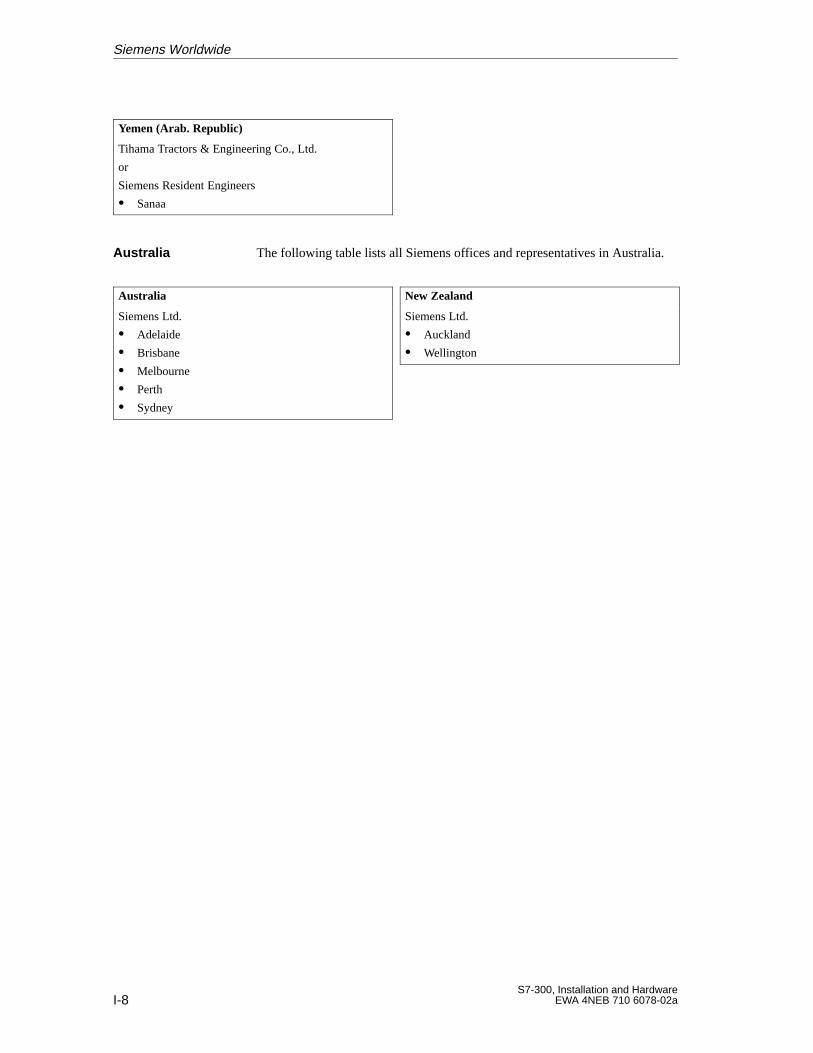
I-8S7-300, Installation and Hardware
EWA 4NEB 710 6078-02a
Yemen (Arab. Republic)
Tihama Tractors & Engineering Co., Ltd.
or
Siemens Resident Engineers
Sanaa
The following table lists all Siemens offices and representatives in Australia.
Australia
Siemens Ltd.
Adelaide
Brisbane
Melbourne
Perth
Sydney
New Zealand
Siemens Ltd.
Auckland
Wellington
Australia
Siemens Worldwide
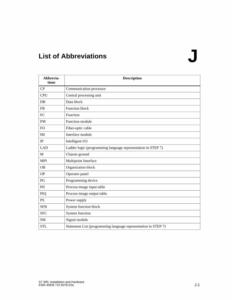
J-1S7-300, Installation and HardwareEWA 4NEB 710 6078-02a
List of Abbreviations
Abbrevia-tions
Description
CP Communication processor
CPU Central processing unit
DB Data block
FB Function block
FC Function
FM Function module
FO Fiber-optic cable
IM Interface module
IP Intelligent I/O
LAD Ladder logic (programming language representation in STEP 7)
M Chassis ground
MPI Multipoint Interface
OB Organization block
OP Operator panel
PG Programming device
PII Process-image input table
PIQ Process-image output table
PS Power supply
SFB System function block
SFC System function
SM Signal module
STL Statement List (programming language representation in STEP 7)
J

J-2S7-300, Installation and Hardware
EWA 4NEB 710 6078-02a
Abkürzungsverzeichnis
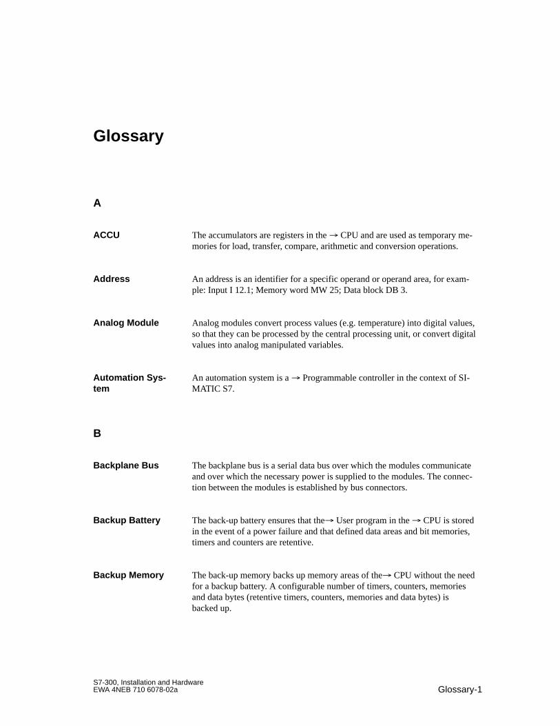
Glossary-1S7-300, Installation and HardwareEWA 4NEB 710 6078-02a
Glossary
A
The accumulators are registers in the CPU and are used as temporary me-mories for load, transfer, compare, arithmetic and conversion operations.
An address is an identifier for a specific operand or operand area, for exam-ple: Input I 12.1; Memory word MW 25; Data block DB 3.
Analog modules convert process values (e.g. temperature) into digital values,so that they can be processed by the central processing unit, or convert digitalvalues into analog manipulated variables.
An automation system is a Programmable controller in the context of SI-MATIC S7.
B
The backplane bus is a serial data bus over which the modules communicateand over which the necessary power is supplied to the modules. The connec-tion between the modules is established by bus connectors.
The back-up battery ensures that the User program in the CPU is storedin the event of a power failure and that defined data areas and bit memories,timers and counters are retentive.
The back-up memory backs up memory areas of the CPU without the needfor a backup battery. A configurable number of timers, counters, memoriesand data bytes (retentive timers, counters, memories and data bytes) isbacked up.
ACCU
Address
Analog Module
Automation Sys -tem
Backplane Bus
Backup Battery
Backup Memory
Glossary-2S7-300, Installation and Hardware
EWA 4NEB 710 6078-02a
Bit memories are part of the System memory of the CPU for storing in-terim results. They can be accessed in units of a bit, byte, word or double-word.
A bus is a communication medium connecting several nodes. Data transmis-sion can be serial or parallel across electrical conductors or fiber-optic cables.
A bus segment is a self-contained section of a serial bus system. Bus seg-ments are interconnected using repeaters.
C
Chassis ground is the totality of all the interconnected inactive parts of apiece of equipment on which a hazardous touch voltage cannot build up evenin the event of a fault.
A code block in SIMATIC S7 is a block which contains a section of theSTEP 7 user program. (as opposed to a Data block which only containsdata)
Communication processors are modules for point-to-point and bus links.
When a central processing unit is started up (e.g. by switching the mode se-lector from STOP to RUN or by switching the power on), organization blockOB 100 (complete restart) is executed before cyclic program execution com-mences. On a complete restart, the process-image input table is read in andthe STEP 7 user program is executed starting with the first command inOB 1.
The programming device online function “Compress” is used to align allvalid blocks contiguously in the RAM of the CPU at the start of the usermemory. This eliminates all gaps which arose when blocks were deleted ormodified.
Assignment of modules to racks/slots and (e.g. for signal modules) addresses.
Data whose contents are related and which should not be separated areknown as consistent data.
For example, the values of analog modules must always be handled consis-tently, that is the value of an analog module must not be corrupted by readingit out at two different times.
Bit Memories
Bus
Bus Segment
Chassis Ground
Code Block
CommunicationProcessor
Complete Restart
Compress
Configuration
Consistent Data
Glossary
Glossary-3S7-300, Installation and HardwareEWA 4NEB 710 6078-02a
Counters are part of the System memory of the CPU. The content of the“counter cells” can by modified by STEP 7 instructions (e.g. count up/down).
Communication processor
Central Processing Unit of the S7 programmable controller with open andclosed-loop control systems, memory, operating system and interface for pro-gramming device.
The cycle time is the time taken by the CPU to scan the User programonce.
Interrupt, Cyclic
D
Data blocks (DB) are data areas in the user program which contain programdata. Global data blocks can be accessed by all code blocks while instancedata blocks are assigned to a specific FB call.
Static data are data which can only be used within a function block. The dataare saved in an instance data block belonging to the function block. The datastored in the instance data block are retained until the next function blockcall.
Temporary data are local data of a block which are stored in the L stack dur-ing execution of a block and which are no longer available after execution.
System diagnostics
The diagnostics buffer is a buffered memory area in the CPU in which diag-nostic events are stored in the order of their occurrence.
Diagnostics-capable modules use diagnostics interrupts to report system er-rors which they have detected to the CPU.
A Master which behaves in accordance with the standard EN 50170, Part3 is known as a DP master.
Counters
CP
CPU
Cycle Time
Cyclic Interrupt
Data Block
Data,Static
Data,Temporary
Diagnostics
Diagnostics Buffer
Diagnostics Inter -rupt
DP Master
Glossary
Glossary-4S7-300, Installation and Hardware
EWA 4NEB 710 6078-02a
A Slave which is operated on the PROFIBUS using the PROFIBUS-DPprotocol and which behaves in accordance with the standard EN 50170, Part3 is known as a DP slave.
E
Electrical connection (equipotential bonding conductor) which gives the bod-ies of electrical equipment and external conducting bodies the same orapproximately the same potential, in order to prevent disturbing or dangerousvoltages from being generated between these bodies.
The error display is one of the possible responses of the operating system to a Runtime error. The other possible responses are: Error response in theuser program, STOP mode on CPU.
If the operating system detects a specific error (e.g. an access error withSTEP 7), it calls the organization block (error OB) which is provided for thiserror and which specifies the subsequent behavior of the CPU.
Reaction to a Runtime error. The operating system can react in the follow-ing ways: switch the programmable controller to STOP mode, call an orga-nization block in which the user can program a reaction, or display the error.
F
Function block
Function
FEPROMs are the same as electrically erasable EEPROMS with reference totheir ability to retain data in the event of a power failure, but they can beerased much more quickly (FEPROM = Flash Erasable Programmable ReadOnly Memory). They are used on the Memory cards.
A function (FC) in accordance with IEC 1131-3 is a Code block without Static data. A function allows parameters to be passed in the user pro-gram. Functions are therefore suitable for programming complex functions,e.g. calculations, which are repeated frequently.
DP Slave
EquipotentialBonding
Error Display
Error Handling viaOB
Error Response
FB
FC
Flash EPROM
Function
Glossary
Glossary-5S7-300, Installation and HardwareEWA 4NEB 710 6078-02a
A function block (FB) in accordance with IEC 1131-3 is a Code blockwith Static data. An FB allows parameters to be passed in the user pro-gram. Function blocks are therefore suitable for programming complex func-tions, e.g. closed-loop controls, mode selections, which are repeated fre-quently.
Grounding which has the sole purpose of safeguarding the intended functionof the electrical equipment. Functional grounding short-circuits interferencevoltage which would otherwise have an impermissible impact on the equip-ment.
G
A GD element is generated by assigning the Global data to be shared andis identified by the global data identifier in the global data table.
A GD circle encompasses a number of CPUs which exchange data by meansof global data communication and which are used as follows:
One CPU sends a GD packet to the other CPUs.
One CPU sends and receives a GD packet from another CPU.
A GD circle is identified by a GD circle number.
A GD packet can consist of one or more GD objects which are transmittedtogether in a frame.
Global data are data which can be addressed from any Code block (FC,FB, OB). In detail, this refers to memories M, inputs I, outputs Q, timers,counters and data blocks DB. Absolute or symbolic access can be made toglobal data.
Global data communication is a procedure used to transfer Global databetween CPUs (without CFBs).
The conducting earth whose electrical potential can be set equal to zero atany point.
In the vicinity of grounding electrodes, the earth can have a potential differ-ent to zero. The term “reference ground” is frequently used to describe thesecircumstances.
Function Block
FunctionalGrounding
GD Element
GD Circle
GD Packet
Global Data
Global Data Com -munication
Ground
Glossary
Glossary-6S7-300, Installation and Hardware
EWA 4NEB 710 6078-02a
To ground means to connect an electrically conducting component to thegrounding electrode (one or more conducting components which have a verygood contact with the earth) across a grounding system.
I
A data block, which is generated automatically, is assigned to each functionblock call in the STEP 7 user program. The values of the input, output andin/out parameters are stored in the instance data block, together with the localblock data.
MPI
The Operating system of the CPU recognizes 10 different runtime levelswhich control the execution of the user program. These runtime levels in-clude interrupts, e.g. process interrupts. When an interrupt is triggered, theoperating system automatically calls an assigned organization block in whichthe user can program the desired response (for example in an FB).
A cyclic interrupt is generated periodically by the CPU in configurable timeintervals. A corresponding Organization block is then executed.
Diagnostic interrupt
Process interrupt
The time-delay interrupt belongs to one of the runtime levels for programexecution on the SIMATIC S7 system. The interrupt is generated after expiryof a time delay started in the user program. A corresponding organizationblock is then executed.
The time-of-day interrupt belongs to one of the priority levels for programexecution in the SIMATIC S7 system. The interrupt is generated on a certaindate (or daily) at a certain time (e.g. 9:50 or every hour, every minute). Acorresponding organization block is then executed.
On isolated I/O modules, the reference potentials of the control and load cir-cuits are galvanically isolated, for example by optocoupler, relay contact ortransformer. Input/output circuits can be connected to a common potential.
Ground (verb)
Instance DataBlock
Interface, Multi-point
Interrupt
Interrupt,Cyclic
Interrupt,Diagnostic
Interrupt,Process
Interrupt, Time-delay
Interrupt,Time-of-Day
Isolated
Glossary
Glossary-7S7-300, Installation and HardwareEWA 4NEB 710 6078-02a
L
The load memory is part of the central processing unit. It contains objectsgenerated by the programming device. It is implemented either as a plug-inmemory card or a permanently integrated memory.
Data, temporary
M
When they are in possession of the Token, masters can send data to othernodes and request data from other nodes (= active node).
Memory cards are memory media in cheque card format for CPUs and CPs.They are implemented as RAM or FEPROM.
Module parameters are values which can be used to control the response ofthe module. A distinction is made between static and dynamic module pa-rameters.
The multipoint interface (MPI) is the programming device interface of SI-MATIC S7. It enables the simultaneous operation of several stations (pro-gramming devices, text displays, operator panels) on one or more centralprocessing units. Each station is identified by a unique address (MPI ad-dress).
MPI
N
One block can be called from another by means of a block call. The nestingdepth is the number of Code blocks which can be activated simulta-neously.
On non-isolated input/output modules, there is an electrical connection be-tween the reference potentials of the control and load circuits.
Load Memory
Local Data
Master
Memory Card
Module Parame -ters
MPI
MPI Address
Nesting Depth
Non-Isolated
Glossary
Glossary-8S7-300, Installation and Hardware
EWA 4NEB 710 6078-02a
O
Organization block
The Operating system of the CPU distinguishes between various priorityclasses, such as cyclic program scanning, process interrupt-driven programscanning, etc. Organization blocks (OBs), in which the S7 user can pro-gram a reaction, are assigned to each priority class. The OBs have differentstandard priorities which determine the order in which they are executed orinterrupted in the event that they are activated simultaneously.
SIMATIC S7 programmable logic controllers recognize the following operat-ing modes: STOP, STARTUP, RUN.
The operating system of the CPU organizes all functions and processes of theCPU which are not associated with a special control task.
Organization blocks (OBs) represent the interface between the operating sys-tem of the CPU and the user program. The processing sequence of the userprogram is defined in the organization blocks.
P
1. Variable of a STEP 7 code block2. Variable for setting the behavior of a module (one or more per module).Each module is delivered with a suitable default setting which can bechanged by configuring the parameters in STEP 7.Parameters can be Static parameters or Dynamic parameters
Unlike static parameters, dynamic parameters of modules can be changedduring operation by calling an SFC in the user program, for example limitvalues of an analog signal input module.
Unlike dynamic parameters, static parameters of modules cannot be changedby the user program, but only by changing the configuration in STEP 7, forexample the input delay on a digital signal input module.
Programmable controller
OB
OB Priority
Operating Mode
Operating Systemof the CPU
Organization Block
Parameters
Parameters, Dy -namic
Parameters, Static
PLC
Glossary
Glossary-9S7-300, Installation and HardwareEWA 4NEB 710 6078-02a
Power supply for the signal and function modules and the process peripheralsconnected to them.
The operating system of an S7-CPU provides up to 26 priority classes (or”runtime levels”) to which various organization blocks are assigned. Thepriority classes determine which OBs interrupt other OBs. If a priority classincludes several OBs, they do not interrupt each other, but are executed se-quentially.
The process image is part of the System memory of the CPU. The signalstates of the input modules are written into the process-image input table atthe start of the cyclic program. At the end of the cyclic program, the signalstates in the process-image output table are transferred to the output modules.
A process interrupt is triggered by interrupt-triggering modules on the occur-rence of a specific event in the process. The process interrupt is reported tothe CPU. The assigned Organization block is then executed in accordancewith the priority of this interrupt.
The product version differentiates between products which have the sameorder number. The product version is increased with each upwardly compat-ible function extension, production-related modification (use of new compo-nents) or bug-fix.
Programmable controllers (PLCs) are electronic controllers whose function issaved as a program in the control unit. The configuration and wiring of theunit are therefore independent of the function of the control system. The pro-grammable controller has the same structure as a computer; it consists of a CPU (central processing unit) with a memory, I/O modules and an internalbus system. The I/Os and the programming language are oriented to controlengineering needs.
Programming devices are essentially personal computers which are compact,portable and suitable for industrial applications. They are equipped with spe-cial hardware and software for SIMATIC programmable controllers.
R
A RAM (Random Access Memory) is a semiconductor read/write memory.
Ground
Power Supply , Ex-ternal
Priority Class
Process Image
Process Interrupt
Product V ersion
ProgrammableController
Programming De -vice
RAM
Reference Ground
Glossary
Glossary-10S7-300, Installation and Hardware
EWA 4NEB 710 6078-02a
Potential with reference to which the voltages of participating circuits areobserved and/or measured.
RESTART mode is activated on a transition from STOP mode to RUN mode.Can be triggered by the Mode selector or after Power On or an operatoraction on the programming device. A Restart is initiated on the S7-300.
Error which occurs during execution of the user program on the program-mable controller (and not in the process).
S
The scan rate determines the frequency with which GD packets are trans-mitted and received on the basis of the CPU cycle.
Bus segment
System function block
System function
Signal modules (SM) represent the interface between the process and the pro-grammable controller. Input and output modules can be digital (Input/outputmodule, digital) or analog. (Input/output module, analog)
A slave can only exchange data with a Master when so requested by themaster.
Programming language for developing user programs for SIMATIC S7 PLCs.
Substitute values are configurable values which output modules transmit tothe process when the CPU switches to STOP mode.
In the event of an input access error, a substitute value can be written to theaccumulator instead of the input value which could not be read (SFC 44).
System diagnostics is the term used to describe the detection, evaluation andsignaling of errors which occur within the programmable controller. Exam-ples of such errors include program errors or module malfunctions. Systemerrors can be displayed with LED indicators or in STEP 7.
Reference Poten -tial
RESTART
Runtime Error
Scan Rate
Segment
SFB
SFC
Signal Module
Slave
STEP 7
Substitute V alue
System Diagnos -tics
Glossary
Glossary-11S7-300, Installation and HardwareEWA 4NEB 710 6078-02a
A system function (SFC) is a Function which is integrated in the operatingsystem of the CPU and which can be called in the STEP 7 user program asrequired.
A system function block (SFB) is a Function block which is integrated inthe operating system of the CPU and which can be called in the STEP 7 userprogram as required.
The system memory is integrated on the central processing unit and imple-mented as a RAM memory. The system memory includes the operand areas(for example timers, counters, bit memories, etc.) as well as the data areas(for example communication buffers) required by the Internal operatingsystem.
T
A terminating resistor is a resistor used to terminate a data communicationline in order to prevent reflection.
Interrupt, Time-Delay
Interrupt, time-of-day
Timers are part of the System memory of the CPU. The contents of the”timer cells” are updated automatically by the operating system asynchro-nously to the user program. STEP 7 instructions are used to define the exactfunction of the timer cells (for example on-delay) and initiate their execution(e.g. start).
Access right on bus
Rate of data transfer (bit/s)
U
Having no galvanic connection to ground
System Function
System FunctionBlock
System Memory
Terminating Resis -tor
Time-Delay Inter -rupt
Time-of-Day Inter -rupt
Timers
Token
Transmission Rate
Ungrounded
Glossary
Glossary-12S7-300, Installation and Hardware
EWA 4NEB 710 6078-02a
The user memory contains the Code and Data blocks of the user pro-gram. The user memory can be integrated in the CPU or can be provided onplug-in memory cards or memory modules. The user program is always exe-cuted in the Work memory of the CPU, however.
The SIMATIC system distinguishes between the Operating system of theCPU and user programs. The latter are created with the programming soft-ware STEP 7 in the available programming languages (ladder logic andstatement list) and saved in code blocks. Data are stored in data blocks.
V
Voltage-independent resistor
W
The work memory is a random-access memory in the CPU which theprocessor access during program execution.
User Memory
User Program
Varistor
Work Memory
Glossary
Index-1S7-300, Installation and HardwareEWA 4NEB 710 6078-02a
Index
AAccessories, F-1
backup battery, 5-5bus connector, 5-5front connector, 5-5key, 5-5labeling strip, 5-5memory card, 5-5power connector, 5-5rechargeable battery, 5-5slot label, 5-5
Accessories , modules, 5-5ACCU, Glossary-1ACT_TINT, B-3Activating OB 10, parameters, 10-26AD_DT_TM, B-11Address, Glossary-1Address allocation, user–oriented, 3-4Address area, CPU 315-2 DP, 11-2Address space, CPU 315-2 DP, 3-5Addresses, analog modules, 3-9Addressing, 3-1
default, 3-2digital modules, 3-7integrated inputs and outputs, 3-10slot-oriented, 3-2
ALARM_S, B-8ALARM_SC, B-8ALARM_SQ, B-8Ambient temperature, permissible, 2-2Analog module, 1-3, Glossary-1
addresses, 3-9Approvals, A-1Area of application, A-1Arrangement
horizontal, 2-2of the modules, 2-6vertical, 2-2
Assignment of parameters, to the CPU, 10-19Automatic restart after Power On, parameters,
10-20
BBackplane bus, Glossary-1Backup
battery, 10-23with backup battery, 8-4with rechargeable battery, 8-4
Backup battery, 5-5, Glossary-1backup, 8-4changing, 9-2disposal, 9-3inserting, 8-4retentivity without, 10-23
Backup memory, Glossary-1Basic circuit diagram, CPU 312 IFM, 10-42BATF, LED, 10-6Battery, Glossary-1Battery fault, 10-6Baud rate, 7-3Bit memories, Glossary-2BLKMOV, B-2Blocks, of the CPU, 10-15Bus, Glossary-2
backplane, Glossary-1Bus cable
connecting to the RS 485 repeater, 7-24length of spur lines, 7-16PROFIBUS, 7-19
Bus connector, 5-5, 7-18activating the terminating resistance, 7-22attaching, 5-6connecting the module, 7-22disconnecting, 7-22purpose, 7-21terminating resistor, 7-9
Bus runtimes, PROFIBUS-DP subnet, 12-10Bus segment, Glossary-2
Siehe auch SegmentBUSF, LED, 11-4, 11-6
Index-2S7-300, Installation and Hardware
EWA 4NEB 710 6078-02a
CCable lengths
in the subnet, 7-14maximum, 7-15
Cables, shielded, 6-10Cabling
EMC rules, 4-20inside buildings, 4-17outside buildings, 4-20–4-32rules concerning lightning protection, 4-20
Calculation, response time, 12-4Calculation example, interrupt response time,
12-17CAN_DINT, B-3CAN_TINT, B-3CE, marking, A-1Changing
modules, 9-4the backup battery, 9-2the rechargeable battery, 9-2
Chassis ground, Glossary-2Clearances, for configuration on one rack, 2-3Clock
of the CPU, 10-3, 10-13parameter block, 10-29register, 10-19
Clock memoriesof the CPU, 10-3parameters, 10-22register, 10-19
Clocksfrequency, 10-22periods, 10-22
Code block, Glossary-2Communication
cyclic loading through, 10-21global data, 10-11PG/OP-CPU, 10-11
Communication processor, 1-4Communication SFCs for configured S7 con-
nections, 10-11Communication SFCs for non–configured S7
connections, 10-11Communication via MPI
cycle load, 12-2number of connections, 10-3
Communications error, OB 87, 10-17Complete restart, Glossary-2Component, open, 2-1
Componentsfor MPI subnet, 7-8for the MPI subnet, 7-18for the PROFIBUS–DP subnet, 7-18of an S7-300, 1-3subnet, 7-8
Compress, Glossary-2CONCAT, B-13Conductor cross–sections, 6-2Conductors
diameter of insulation, 6-2length of insulation to be stripped, 6-2number of, 6-2
Configuration, Glossary-2arrangement of the modules, 2-6electrical, 4-1grounded reference potential, 4-12in TN -S-power system, 4-10in TN-S-power system, 4-10lightning protection, 4-23maximum, 2-9mechanical, 2-1mechanical configuration, 2-1mounting dimensions, 2-3overvoltage protection, 4-23special heights, 2-5ungrounded reference potential, 4-13with isolated modules, 4-14with non–isolated modules, 4-16with process peripherals, 4-8
ConfiguringCPU 315-2 DP as DP slave, 11-24with DP master, 11-24
Configuring frame, 11-24example, 11-29format
non-S7 format, 11-30S7 format, 11-27
Connectinga programming device, 8-6the bus connector, 7-22
Connecting cablefor interface modules, 2-8PROFIBUS, 1-4
Connector cables, tightening torque, 6-2Consistent data, Glossary-2Consistent useful data, CPU 315-2 DP, 11-2CONT_C, B-9
CPU 314 IFM, 10-62
Index
Index-3S7-300, Installation and HardwareEWA 4NEB 710 6078-02a
CONT_S, B-9CPU 314 IFM, 10-62
Contents of the manual, iiiConversion factor, GD circle, 10-12Correction factor (of the clock), parameters,
10-29Counter
CPU 312 IFM, 10-43CPU 314 IFM, 10-62
Counter A/B, CPU 314 IFM, 10-62Counters, Glossary-3
Siehe auch S7–Zählerof the CPU, 10-2
CPU, 1-3accessories, 5-5analog inputs, 10-2analog outputs, 10-2assignment of parameters, 10-19blocks, 10-15clock, 10-3, 10-13clock memories, 10-3connection of the power supply unit, 10-9counters, 10-2DBs, 10-15digital inputs, 10-2digital outputs, 10-2dimension drawing, D-1DP address area, 10-2fault LEDs, 10-6FBs, 10-15FCs, 10-15FCs (IEC-), B-11load memory, 10-2local data, 10-3memory bit, 10-2memory reset, 8-11mode selector, 10-5MPI, 10-3, 10-10nesting depth, 10-3OBs, 10-15operating hours counter, 10-3, 10-13operating system, Glossary-8parameters, 10-19priority classes, 10-3
process image, 10-2PROFIBUS DP interface, 10-4RAM, 10-2reference data functions, 10-7retentive data, 10-3SFBs, 10-15, B-2SFBs (IEC-), B-10SFCs, 10-15, B-2speed, 10-2status LEDs, 10-6system state list, C-1test functions, 10-7timers, 10-2wiring, 6-3
CPU 312 IFM, 10-36basic circuit diagram, 10-42characteristics, 10-36connecting the power supply, 10-41grounded configuration, 10-41integrated functions, 10-43performance characteristics, 10-2short-circuit characteristics, 10-42technical specifications, 10-37terminal connections, 10-41
CPU 313, 10-44characteristic features, 10-44performance characteristics, 10-2technical specifications, 10-45
CPU 314, 10-47characteristic features, 10-47performance characteristics, 10-2technical specifications, 10-48
CPU 314 IFM, 10-50basic circuit diagrams, 10-60characteristic features, 10-50integrated functions, 10-62performance characteristics, 10-2technical specifications, 10-51wiring schematic, 10-59
CPU 315, 10-63characteristic features, 10-63performance characteristics, 10-2technical specifications, 10-64
Index
Index-4S7-300, Installation and Hardware
EWA 4NEB 710 6078-02a
CPU 315-2 DP, 10-66address areas, 11-2address space, 3-5bus interruption, 11-14characteristic features, 10-66characteristics as DP slave, 11-11consistent useful data, 11-2diagnostic addresses for PROFIBUS, 11-13display elements as DP master, 11-4display elements as DP slave, 11-6DP master, 11-3DP slave, 11-5parameter assignment frame, 11-26performance characteristics, 10-2startup as a DP master, 8-15startup as a DP slave, 8-16status changes, 11-14technical specifications, 10-68transfer memory, 11-7
CPU 316, 10-70characteristic features, 10-70performance characteristics, 10-2technical specifications, 10-71
CPUs, 10-1CREAT_DB, B-3CSA, A-2CTD, B-10CTRL_RTM, B-2CTU, B-10CTUD, B-10Current consumption, of an S7-300, 4-4Current consumption balance, 4-6Custumer Support, viiCycle control, execution time, 12-7Cycle extension, through interrupts, 12-11Cycle interrupts, register, 10-19Cycle load, communication via MPI, 12-2Cycle monitoring time, parameters, 10-21Cycle time, 12-2, Glossary-3
calculation example, 12-12components, 12-2extension, 12-3
Cyclic interrupt, 10-27, Glossary-6OB 35, 10-16reproducibility, 12-18
Cyclic interrupts, parameter block, 10-27Cyclic loading through communication, param-
eters, 10-21
DD_TOD_DT, B-11Data
consistent, 11-2, Glossary-2static, Glossary-3temporary, Glossary-3
Data block, Glossary-3parameters, 10-24
Data, retentive, of the CPU, 10-3DBs, of the CPU, 10-15DC 24 V supply, 4-3Default addressing, 3-2Delay, of inputs / outputs, 12-9Delay interrupt
OB 20, 10-16reproducibility, 12-18
DELETE, B-13Device. Siehe NodesDevice master file, 11-10Device-related diagnostic data, CPU 315-2 DP
as DP slave, 11-22DI_STRNG, B-14Diagnosis/clock, register, 10-28Diagnostic addresses, CPU 315-2 DP, 11-13Diagnostic buffer, Glossary-3Diagnostic byte, master PROFIBUS address,
CPU 315-2 DP as DP slave, 11-20Diagnostic data
device-related, CPU 315-2 DP as DP slave,11-22
identifier-related, CPU 315-2 DP as DPslave, 11-21
Diagnostic data for the CPU 315-2 DP, as DPslave, 11-12
Diagnostic interrupt, Glossary-3CPU 315-2 DP as DP slave, 11-23OB 82, 10-16
Diagnostic interrupt response times, of theCPUs, 12-16
DiagnosticsCPU 315-2 DP as DP slave, 11-16register, 10-19, 10-28system, Glossary-10
Digital module, 1-3addressing, 3-7
Dimension drawing, CPU, D-1DIS_AIRT, B-4
Index
Index-5S7-300, Installation and HardwareEWA 4NEB 710 6078-02a
DIS_IRT, B-4Disposal, v
of the backup battery, 9-3DMSK_FLT, B-4Documentation package, iiiDP address area, of the CPU, 10-2DP master, Glossary-3
CPU 315-2 DP, 8-15, 11-3display elements of the CPU 315-2 DP, 11-4
DP slave, Glossary-4CPU 315-2 DP, 8-16, 11-5diagnostics, requesting, 11-17display elements of the CPU 315-2 DP, 11-6
DP slave diagnostics, format, 11-17DP_PRAL, B-6DPNRM_DG, B-6DPRD_DAT, B-6DPWR_DAT, B-6DRUM, B-9DT_DATE, B-11DT_DAY, B-11DT_TOD, B-11
EElectrical configuration, 4-1Electrical influences, protection against, 4-3Emergency OFF facilities, 4-2EN_AIRT, B-4EN_IRT, B-4EQ_DT, B-12EQ_STRNG, B-12Equipotential bonding, 4-25, Glossary-4Error, battery fault, 10-6Error display, Glossary-4Error response, Glossary-4Error when direct access to I/O, OB 122, 10-17Error/fault
communications error, OB 87, 10-17direct access to I/O, OB 122, 10-17power supply fault, OB 81, 10-17program execution errors, OB 85, 10-17programming error, OB 121, 10-17time-out, OB 80, 10-17
Error/fault response, 10-17ESD guideline, E-1
Execution timecycle control, 12-7FC (IEC-), B-11operating system, 12-7process image update, 12-7SFB (IEC-), B-10SFBs, B-2SFCs, B-2user program, 12-2, 12-8
FFault LEDs, of the CPU, 10-6FBs, of the CPU, 10-15
Index
Index-6S7-300, Installation and Hardware
EWA 4NEB 710 6078-02a
FCAD_DT_TM, B-11CONCAT, B-13D_TOD_DT, B-11DELETE, B-13DI_STRNG, B-14DT_DATE, B-11DT_DAY, B-11DT_TOD, B-11EQ_DT, B-12EQ_STRNG, B-12FIND, B-13GE_DT, B-12GE_STRNG, B-12GT_DT, B-12GT_STRNG, B-12I_STRNG, B-14INSERT, B-13LE_DT, B-12LE_STRNG, B-12LEFT, B-13LEN, B-13LIMIT , B-14LT_DT, B-12LT_STRNG, B-12MAX, B-14MID, B-13MIN, B-14NE_DT, B-12NE_STRNG, B-12R_STRNG, B-14REPLACE, B-13RIGHT, B-13S5TI_TIM, B-11SB_DT_DT, B-11SB_DT_TM, B-11SEL, B-14STRNG_DI, B-14STRNG_I, B-14STRNG_R, B-14TIM_S5TI, B-11
FC (IEC-), execution time, B-11FCs, of the CPU, 10-15FEPROM
12 V, 8-25 V, 8-2memory card, 8-2
FILL, B-2FIND, B-13FM, approval, A-2Force, 10-7Force job, 10-6
FRCE, LED, 10-6FREQ_MES, B-9Frequency, of clocks, 10-22Frequency meter
CPU 312 IFM, 10-43CPU 314 IFM, 10-62
Front connector, 5-5wiring, 6-6wiring position, 6-7
Front connector coding, 6-9removing, 9-6removing from the front connector, 9-7
Function, FC, Glossary-4Function block, FB, Glossary-5Function module, 1-4Functional grounding, Glossary-5Fuses, replacing, 9-8
GGADR_LGC, B-5GD circle, 10-11, Glossary-5
conversion factor, 10-12receive conditions, 10-12send conditions, 10-12
GD element, Glossary-5GD packet, Glossary-5GE_DT, B-12GE_STRNG, B-12Global data, Glossary-5
send cycles, 10-12Global data communication, 10-11Ground, Glossary-5, Glossary-6Grounded configuration, CPU 312 IFM, 10-41Grounding concept, 4-9GSD file, 11-10GT_DT, B-12GT_STRNG, B-12Guideline, ESD, E-1Guidelines, for operating an S7–300, 4-2
HHardware test on complete restart, parameters,
10-20Highest MPI address, 7-4
parameters, 10-30Highest PROFIBUS address, 7-4HS_COUNT, B-9HSC_A_B, B-9
Index
Index-7S7-300, Installation and HardwareEWA 4NEB 710 6078-02a
II_ABORT, B-7I_GET, B-7I_PUT, B-7I_STRNG, B-14Identifier, configuring frame, S7 format, 11-28Identifier-related diagnostic data, CPU 315-2
DP as DP slave, 11-21IEC 1131, A-1IEC function, B-1IEC-FC, execution time, B-11IEC-SFB, execution time, B-10Incoming supply, grounded, 4-8Initializing, CPU 315-2 DP as DP slave, 11-24Inputs
analog, 10-2delay time, 12-9digital, 10-2
Inputs/outputsintegrated, CPU 312 IFM, 10-36integrated, CPU 314 IFM, 10-50
INSERT, B-13Installation, of the modules, 5-6Installation rules, PROFIBUS bus cable, 7-20Installing
an S7-300, 5-1the rail, 5-2
Instance data block, Glossary-6Integrated functions, CPU 314 IFM, 10-62Integrated I/O, register, 10-19Integrated I/Os, parameter block, 10-31Integrated inputs and outputs, addressing, 3-10Integrated inputs/outputs
of the CPU 312 IFM, 10-36of the CPU 314 IFM, 10-50wiring, 6-6
Interface module, 1-4, 2-7Accessories, 5-5
Interface modules, connecting cable, 2-8Internet, up-to-date information, viiInterrupt, Glossary-6
cyclic, Glossary-6diagnostic, Glossary-3process, Glossary-9time–delay, Glossary-6time–of–day, Glossary-6
Interrupt inputs, parameter, 10-32Interrupt response time, calculation example,
12-17Interrupt response times
of the CPUs, 12-15of the signal modes, 12-16
InterruptsCPU 315-2 DP as DP slave, 11-16cycle extension, 12-11register, 10-19, 10-25
Isolated, Glossary-6Isolation monitoring, 4-13
KKey, 5-5
inserting, 5-8Key-operated mode selector. Siehe Betriebsar-
tenschalter
LL2 address, recommendation, 7-8L2-DP, 7-2L2-DP network, rules for configuring, 7-7Labeling strip, 5-5, 6-9LE_DT, B-12LE_STRNG, B-12LED
5 VDC, 10-6BATF, 10-6BUSF, 11-4, 11-6FRCE, 10-6RUN, 10-6SF, 10-6SF DP, 11-4, 11-6STOP, 10-6
LEFT, B-13LEN, B-13Length of insulation to be stripped, 6-2LGC_GADR, B-5Lightning protection, 4-23
cabling, 4-20high-voltage protection, 4-26low–voltage protection, 4-29, 4-30
Lightning protection zone concept, 4-23Lightning protection zones, 4-24Lightning strike, effects, 4-24LIMIT , B-14Load circuit, ground, 4-9Load memory, Glossary-7
of the CPU, 10-2Load power supplies, characteristics, 4-9Load power supply, from PS 307, 4-11Local data, Glossary-7
of the CPU, 10-3LT_DT, B-12
Index
Index-8S7-300, Installation and Hardware
EWA 4NEB 710 6078-02a
LT_STRNG, B-12
MMaintenance. Siehe wechselnManufacturer identification, format, CPU 315-2
DP as DP slave, 11-20Master PROFIBUS address, format, 11-20MAX, B-14Maximum configuration, 2-9Memory
backup, Glossary-1load, Glossary-7system, Glossary-11user, Glossary-12work, Glossary-12
Memory bit, of the CPU, 10-2Memory bytes, parameter, 10-24Memory card, 5-5, Glossary-7
12 V FEPROM, 8-25 V FEPROM, 8-2changing, 8-3plugging in, 8-2–8-16purpose, 8-2
Memory reset, 8-11internal CPU events, 8-13MPI parameter, 8-13
MID, B-13MIN, B-14Mode
parameter block, 10-34RUN, 10-6STOP, 10-6
Mode selector, 10-5MRES, 10-5resetting with, 8-12RUN, 10-5RUN-P, 10-5STOP, 10-5
Modify variable, 10-7Module
accessories, 5-5, F-1mounting dimensions, 2-5non–isolated, 4-16
Module parameters, Glossary-7Module start address, 3-2Modules
arrangement, 2-6installing, 5-6isolated, 4-14replacing, 9-4
Monitor variable, 10-7Monitoring time (... parameters to modules),
parameters, 10-20Monitoring time (... ready signal from modules),
parameters, 10-20Mounting, the RS 485 repeater, 7-23Mounting dimensions
of the modules, 2-5S7-300-configuration, 2-3
MPI, 10-10–10-12, Glossary-7definition, 7-2guaranteed connections, 10-3of the CPU, 10-3
MPI address, 7-4FMs and CPs, 7-5highest, 7-4parameter, 10-30parameters, 10-30recommendations, 7-8register, 10-19rules, 7-5
MPI address, highest, parameters, 10-30MPI addresses
parameter, 10-30register, 10-30
MPI networkdata packets in the, 7-6rules for configuring, 7-7
MPI subnetcable lengths, 7-14components, 7-8, 7-18configuration example, 7-11, 7-13segment, 7-14
MRES, mode selector, 10-5MSK_FLT, B-4Multipoint interface MPI. Siehe MPI
NNE_DT, B-12NE_STRNG, B-12Nesting depth, Glossary-7
of the CPU, 10-3Net. Siehe SubnetzNetwork components, 7-18Node, 7-3Nodes, number of, 7-3Non–isolated, Glossary-7
Index
Index-9S7-300, Installation and HardwareEWA 4NEB 710 6078-02a
OOB, Glossary-8OB 1, 10-16
start event, 10-16OB 10, 10-16
start event, 10-16OB 10 priority, parameter, 10-26OB 10 start date, parameters, 10-26OB 10 start time, parameters, 10-26OB 10, execution, parameter, 10-26OB 100, 10-16
start event, 10-16OB 121, 10-17
start events, 10-17OB 122, 10-17
start events, 10-17OB 20, 10-16
start event, 10-16OB 35, 10-16
start event, 10-16OB 35 periodic occurrence, parameters, 10-27OB 35 priority, parameter, 10-27OB 40, 10-16
start event, 10-16start information for inputs/outputs, 10-33
OB 40, priority, parameters, 10-25OB 80, 10-17
start events, 10-17OB 81, 10-17
start events, 10-17OB 82, 10-16
start events, 10-16OB 85, 10-17
start events, 10-17OB 86, 10-17
start events, 10-17OB 87, 10-17
start events, 10-17OB priority, Glossary-8OB20 priority, parameter, 10-25OBs
of the CPU, 10-15start events, 10-16
Open component, 2-1Operating an S7-300
guidelines, 4-2rules, 4-2
Operating hours counter, of the CPU, 10-3,10-13
Operating mode, Glossary-8Operating system
execution time, 12-7of the CPU, Glossary-8
Organization block, Glossary-8Outputs
analog, 10-2delay time, 12-9digital, 10-2
Overvoltage, induced, 4-21Overvoltage protection, 4-21, 4-23Overvoltages, 4-23
PParameter
interrupt inputs, 10-32memory bytes, 10-24MPI address, 10-30MPI addresses, 10-30OB 10 priority, 10-26OB 10, execution, 10-26OB 20 priority, 10-25OB 35 priority, 10-27password, 10-34process mode, 10-34protection level, 10-34S7-counters, 10-24S7-Timer, 10-24test mode, 10-34
Parameter assignment frame, 11-24, 11-25for CPU 315-2 DP, 11-26
Parameter blockcyclic interrupts, 10-27integrated I/Os, 10-31
Parameterblock. Siehe Register
Index
Index-10S7-300, Installation and Hardware
EWA 4NEB 710 6078-02a
Parameters, Glossary-8activating OB 10, 10-26Automatic restart after Power On, 10-20clock memories, 10-22correction factor (of the clock), 10-29CPU, 10-19cycle monitoring time, 10-21cyclic loading through communication,
10-21data block, 10-24hardware test on complete restart, 10-20module, Glossary-7monitoring time (... parameters to modules),
10-20monitoring time (... ready signal from mod-
ules), 10-20MPI address, 10-30MPI address, highest, 10-30OB 10 start date, 10-26OB 10 start time, 10-26OB 35 periodic occurrence, 10-27OB 40 priority, 10-25signal cause of STOP, 10-28startup on setpoint configuration not equal to
actual configuration, 10-20synchronisation (of the clock), 10-29
PARM_MOD, B-6Password, parameter, 10-34Performance characteristics, CPU, 10-2Periods, of clocks, 10-22PG functions, via the PROFIBUS-DP interface,
7-6PG/OP-CPU-communication, 10-11POS, B-9Positioning, CPU 314 IFM, 10-62Power connector, 5-5, 6-3Power loss balance, 4-6Power losses, of an S7-300, 4-4Power supply, 1-3
24 VDC, 4-3connection to CPU, 10-9setting the voltage selector switch, 6-5
Power supply fault, OB 81, 10-17Power supply module
Accessoiries, 5-5wiring, 6-3
Priority, OB, Glossary-8Priority class, Glossary-9Priority classes, of the CPU, 10-3
Process image, Glossary-9of the CPU, 10-2
Process image update, execution time, 12-7Process interrupt, Glossary-9
CPU 312 IFM, 10-43CPU 314 IFM, 10-62CPU 315-2 DP as DP slave, 11-23OB 40, 10-16
Process interrupt handling, 12-16Process mode, parameter, 10-34Product version, Glossary-9PROFIBUS address, 7-4
highest, 7-4rules, 7-5
PROFIBUS bus cable, 7-18, 7-19installation rules, 7-20
PROFIBUS connecting cable, 1-4PROFIBUS DP interface, of the CPU, 10-4PROFIBUS subnet, segment, 7-14PROFIBUS–DP subnet
cable lengths, 7-14components, 7-18
PROFIBUS-DP, startup, 8-14PROFIBUS-DP interface, PG functions via, 7-6PROFIBUS-DP subnet
bus runtimes, 12-10configuration example, 7-12
Program execution errors, OB 85, 10-17Programming device
Siehe auch PGconnected to the network via a spur line, 8-9connecting, 8-6connecting to an S7-300, 8-7connecting to several nodes, 8-8in an ungrounded configuration, 8-10installed in a network, 8-8must be equipped with, 8-6
Programming device cable, 1-4Programming error, OB 121, 10-17Protection, parameter block, 10-34Protection against electrical influences, 4-3Protection level, parameter, 10-34Protection/mode, register, 10-19, 10-34Protective grounding conductor, for the rail, 5-4Protective measures, for a plant, 4-8PS 307, power supply module, 5-5PULSEGEN, B-9
CPU 314 IFM, 10-62
Index
Index-11S7-300, Installation and HardwareEWA 4NEB 710 6078-02a
QQRY_DINT, B-3QRY_TINT, B-3
RR_STRNG, B-14Rail, 1-3
fixing holes, 5-3fixing screws, 5-3installing, 5-2length, 2-5protective grounding conductor, 5-4
RAM, of the CPU, 10-2RD_LGADR, B-5RD_REC, B-6RD_SINFO, B-5RDSYSST, B-5RE_TRIGR, B-4READ_CLK, B-2READ_ERR, B-4READ_RTM, B-2Receive conditions, GD circle, 10-12Rechargeable battery, 5-5
backup, 8-4changing, 9-2inserting, 8-4
Recycling, vReference data functions, of the CPU, 10-7Reference literature, G-1Reference potential
grounded, 4-12ungrounded, 4-13
Registerdiagnosis/clock, 10-28–10-29in general, 10-30interrupts, 10-25MPI addresses, 10-30protection/mode, 10-34retentive areas, 10-23scan cycle/clock memories, 10-21–10-22startup, 10-20time-of-day interrupts, 10-26
Repeater. Siehe RS 485–RepeaterREPL_VAL, B-4REPLACE, B-13Replacing
fuses, 9-8modules, 9-4
Reproducibility, delay / cyclic interrupts, 12-18Reset, with mode selector, 8-12, 10-5
Response time, 12-4calculation, 12-4, 12-5, 12-6calculation example, 12-12diagnostic interrupt, 12-15factors, 12-4longest, 12-6process interrupt, 12-15shortest, 12-5
RESTART, Glossary-10Restart
OB 100, 10-16of the plant, 4-2
Retentive areas, register, 10-19, 10-23Retentivity, 10-23RIGHT, B-13RS 485 repeater, 1-4, 7-7, 7-18, 7-23
connecting the bus cable, 7-24mounting, 7-23terminating resistor, 7-9
Rulesfor configuring a network, 7-7for operating an S7–300, 4-2for wiring, 6-2
RUNLED, 10-6mode, 10-6mode selector, 10-5
RUN-P, mode selector, 10-5Runtime error, Glossary-10
SS5TI_TIM, B-11S7 timer, parameter, 10-24S7 timers, updating, 12-8S7-300, 1-2
accessories, F-1components, 1-3grounding concept, 4-9installing, 5-1spare parts, F-1wiring, 6-1
S7-counters, parameter, 10-24SB_DT_DT, B-11SB_DT_TM, B-11Scan cycle, OB 1, 10-16Scan cycle/clock memories, register, 10-21Scan rate, Glossary-10Scan-cycle, register, 10-19Scope, of this manual, iv
Index

Index-12S7-300, Installation and Hardware
EWA 4NEB 710 6078-02a
Segment, 7-3MPI subnet, 7-14PROFIBUS subnet, 7-14
SEL, B-14Send conditions, GD circle, 10-12Send cycles, for global data, 10-12SET_CLK, B-2SET_RTM, B-2SET_TINT, B-3SF, LED, 10-6SF DP, LED, 11-4, 11-6SFB, B-1
CONT_C, B-9CONT_S, B-9CTD, B-10CTU, B-10CTUD, B-10DRUM, B-9execution time, B-2FREQ_MES, B-9HS_COUNT, B-9HSC_A_B, B-9POS, B-9PULSEGEN, B-9TOF, B-10TON, B-10TP, B-10
SFB (IEC-), execution time, B-10SFBs, of the CPU, 10-15SFC, B-1
ACT_TINT, B-3ALARM_S, B-8ALARM_SC, B-8ALARM_SQ, B-8BLKMOV, B-2CAN_DINT, B-3CAN_TINT, B-3CREAT_DB, B-3CTRL_RTM, B-2DIS_AIRT, B-4DIS_IRT, B-4DMSK_FLT, B-4DP_PRAL, B-6DPNRM_DG, B-6DPRD_DAT, B-6DPWR_DAT, B-6EN_AIRT, B-4EN_IRT, B-4execution time, B-2FILL, B-2GADR_LGC, B-5I_ABORT, B-7
I_GET, B-7I_PUT, B-7LGC_GADR, B-5MSK_FLT, B-4PARM_MOD, B-6PD_LGADR, B-5QRY_DINT, B-3QRY_TINT, B-3RD_REC, B-6RD_SINFO, B-5RDSYSST, B-5RE_TRIGR, B-4READ_CLK, B-2READ_ERR, B-4READ_RTM, B-2REPL_VAL, B-4SET_CLK, B-2SET_RTM, B-2SET_TINT, B-3SRT_DINT, B-3STP, B-4TIME_TICK, B-2WAIT, B-4WR_DPARM, B-6WR_PARM, B-6WR_REC, B-6WR_USMSG, B-5X_ABORT, B-7X_GET, B-7X_PUT, B-7X_RCV, B-7X_SEND, B-7
SFCs, of the CPU, 10-15Shield connecting element, 6-10Short-circuit characteristics, CPU 312 IFM,
10-42Signal cause of STOP, parameters, 10-28Signal module, 1-3, Glossary-10
Accessories, 5-5SIMATIC S7, reference literature, G-1SIMATIC TOP connect, 1-4SINEC L2-DP. Siehe PROFIBUS DPSlot label, 5-5, 5-9Slot number, 3-2Slot numbers, 5-9Spare parts, F-1Speed, of the CPU, 10-2Spur line, 7-7Spur lines, length, 7-16SRT_DINT, B-3Standards, A-1Start events, for OBs, 10-16
Index
Index-13S7-300, Installation and HardwareEWA 4NEB 710 6078-02a
Start information for inputs/outputs, OB 40,10-33
StartupCPU 315-2 DP as a DP master, 8-15CPU 315-2 DP as a DP slave, 8-16of the CPU 315-2 DP as a DP slave, 8-16PROFIBUS-DP, 8-14register, 10-19, 10-20
Startup on setpoint configuration not equal toactual configuration, parameters, 10-20
Station status, format, CPU 315-2 DP as DPslave, 11-18
Status block, 10-7Status LEDs, of the CPU, 10-6STOP
LED, 10-6mode, 10-6mode selector, 10-5
STP, B-4Strain relief, 6-8STRNG_DI, B-14STRNG_I, B-14STRNG_R, B-14Sublist, System state list, C-1Subnet
Siehe auch MPI–Subnetzcomponents, 7-8configuration example, 7-13
Subnet failure (DP), OB 86, 10-17Substitute value, Glossary-10Surge impedance. Siehe Terminating resistorSurge protection, components, 4-29, 4-30Surges, 4-24Synchronisation (of the clock), parameters,
10-29System diagnostics, Glossary-10
Definition, 10-28System error/fault, 10-6System function, SFC, Glossary-11System function block, SFB, Glossary-11System functions, B-1System memory, Glossary-11System state list, C-1
sublist, C-1System voltage, 4-2SZL. Siehe SystemzustandslisteSZL-ID, structure, C-2
TTerminal element, 6-10
Terminating resistance, activating on the busconnector, 7-22
Terminating resistor, 7-9, Glossary-11example, 7-10on the bus connector, 7-9on the RS 485 repeater, 7-9
Test functions, of the CPU, 10-7Test mode, parameter, 10-34Tightening torque, for connecting cables, 6-2TIM_S5TI, B-11Time–delay interrupt, Glossary-6Time–of–day interrupt, Glossary-6Time-of-day interrupt, OB 10, 10-16Time-of-day interrupts, register, 10-19, 10-26Time-out, OB 80, 10-17TIME_TICK, B-2Timer. Siehe S7–TimerTimers, Glossary-11
of the CPU, 10-2TOF, B-10TON, B-10TP, B-10Transfer memory
CPU 315-2 DP, 11-7for transferring useful data, 11-7
Type file, 11-10
UUL, A-2Ungrounded, Glossary-11Ungrounded configuration, connecting a pro-
gramming device, 8-10Updating, of S7 timers, 12-8Useful data, consistent, CPU 315-2 DP, 11-2User memory, Glossary-12User program, Glossary-12
execution time, 12-8User program execution time, 12-2User–oriented address allocation, 3-4
VVersion. Siehe ErzeugnisstandVoltage selector switch, setting to power supply,
6-5
Index
Index-14S7-300, Installation and Hardware
EWA 4NEB 710 6078-02a
WWAIT, B-4Wiring
an S7-300, 6-1integrated inputs/outputs, 6-6the CPU, 6-3the front connector, 6-6the power supply module, 6-3
Wiring position, of the front connector, 6-7Wiring rules, 6-2Work memory, Glossary-12WR_DPARM, B-6
WR_PARM, B-6WR_REC, B-6WR_USMSG, B-5
XX_ABORT, B-7X_GET, B-7X_PUT, B-7X_RCV, B-7X_SEND, B-7
Index
1S7-300, Installation and HardwareEWA 4NEB 710 6078-02a
Siemens AG
A&D AS E 48
Postfach 1963
D–92209 Amberg
Federal Republic of Germany
From:
Your Name: _ _ _ _ _ _ _ _ _ _ _ _ _ _ _ _ _ _ _ _ _ _ _ _ _ _ _ _ _ _ _
Your Title: _ _ _ _ _ _ _ _ _ _ _ _ _ _ _ _ _ _ _ _ _ _ _ _ _ _ _ _ _ _
Company Name:_ _ _ _ _ _ _ _ _ _ _ _ _ _ _ _ _ _ _ _ _ _ _ _ _ _ _ _ _ _
Street: _ _ _ _ _ _ _ _ _ _ _ _ _ _ _ _ _ _ _ _ _ _ _ _ _ _ _ _ _ _ _
City, Zip Code:_ _ _ _ _ _ _ _ _ _ _ _ _ _ _ _ _ _ _ _ _ _ _ _ _ _ _ _ _
Country: _ _ _ _ _ _ _ _ _ _ _ _ _ _ _ _ _ _ _ _ _ _ _ _ _ _ _ _ _ _
Phone: _ _ _ _ _ _ _ _ _ _ _ _ _ _ _ _ _ _ _ _ _ _ _ _ _ _ _ _ _ _
Please check any industry that applies to you:
Automotive
Chemical
Electrical Machinery
Food
Instrument and Control
Nonelectrical Machinery
Petrochemical
Pharmaceutical
Plastic
Pulp and Paper
Textiles
Transportation
Other _ _ _ _ _ _ _ _ _ _ _ _ _
2S7-300, Installation and Hardware
EWA 4NEB 710 6078-02a
Additional comments:
_ _ _ _ _ _ _ _ _ _ _ _ _ _ _ _ _ _ _ _ _ _ _ _ _ _ _ _ _ _ _ _ _ _ _ _ _
_ _ _ _ _ _ _ _ _ _ _ _ _ _ _ _ _ _ _ _ _ _ _ _ _ _ _ _ _ _ _ _ _ _ _ _ _
_ _ _ _ _ _ _ _ _ _ _ _ _ _ _ _ _ _ _ _ _ _ _ _ _ _ _ _ _ _ _ _ _ _ _ _ _
_ _ _ _ _ _ _ _ _ _ _ _ _ _ _ _ _ _ _ _ _ _ _ _ _ _ _ _ _ _ _ _ _ _ _ _ _
_ _ _ _ _ _ _ _ _ _ _ _ _ _ _ _ _ _ _ _ _ _ _ _ _ _ _ _ _ _ _ _ _ _ _ _ _
_ _ _ _ _ _ _ _ _ _ _ _ _ _ _ _ _ _ _ _ _ _ _ _ _ _ _ _ _ _ _ _ _ _ _ _ _
_ _ _ _ _ _ _ _ _ _ _ _ _ _ _ _ _ _ _ _ _ _ _ _ _ _ _ _ _ _ _ _ _ _ _ _ _
_ _ _ _ _ _ _ _ _ _ _ _ _ _ _ _ _ _ _ _ _ _ _ _ _ _ _ _ _ _ _ _ _ _ _ _ _
_ _ _ _ _ _ _ _ _ _ _ _ _ _ _ _ _ _ _ _ _ _ _ _ _ _ _ _ _ _ _ _ _ _ _ _ _
_ _ _ _ _ _ _ _ _ _ _ _ _ _ _ _ _ _ _ _ _ _ _ _ _ _ _ _ _ _ _ _ _ _ _ _ _
_ _ _ _ _ _ _ _ _ _ _ _ _ _ _ _ _ _ _ _ _ _ _ _ _ _ _ _ _ _ _ _ _ _ _ _ _
_ _ _ _ _ _ _ _ _ _ _ _ _ _ _ _ _ _ _ _ _ _ _ _ _ _ _ _ _ _ _ _ _ _ _ _ _
Remarks Form
Your comments and recommendations will help us to improve the quality and usefulnessof our publications. Please take the first available opportunity to fill out this questionnaireand return it to Siemens.
Please give each of the following questions your own personal mark within the rangefrom 1 (very good) to 5 (poor).
1. Do the contents meet your requirements?
2. Is the information you need easy to find?
3. Is the text easy to understand?
4. Does the level of technical detail meet your requirements?
5. Please rate the quality of the graphics/tables:

1S7-300, Installation and HardwareEWA 4NEB 710 6078-02a
Siemens AG
A&D AS E 48
Postfach 1963
D–92209 Amberg
Federal Republic of Germany
From:
Your Name: _ _ _ _ _ _ _ _ _ _ _ _ _ _ _ _ _ _ _ _ _ _ _ _ _ _ _ _ _ _ _
Your Title: _ _ _ _ _ _ _ _ _ _ _ _ _ _ _ _ _ _ _ _ _ _ _ _ _ _ _ _ _ _
Company Name:_ _ _ _ _ _ _ _ _ _ _ _ _ _ _ _ _ _ _ _ _ _ _ _ _ _ _ _ _ _
Street: _ _ _ _ _ _ _ _ _ _ _ _ _ _ _ _ _ _ _ _ _ _ _ _ _ _ _ _ _ _ _
City, Zip Code:_ _ _ _ _ _ _ _ _ _ _ _ _ _ _ _ _ _ _ _ _ _ _ _ _ _ _ _ _
Country: _ _ _ _ _ _ _ _ _ _ _ _ _ _ _ _ _ _ _ _ _ _ _ _ _ _ _ _ _ _
Phone: _ _ _ _ _ _ _ _ _ _ _ _ _ _ _ _ _ _ _ _ _ _ _ _ _ _ _ _ _ _
Please check any industry that applies to you:
Automotive
Chemical
Electrical Machinery
Food
Instrument and Control
Nonelectrical Machinery
Petrochemical
Pharmaceutical
Plastic
Pulp and Paper
Textiles
Transportation
Other _ _ _ _ _ _ _ _ _ _ _ _ _

2S7-300, Installation and Hardware
EWA 4NEB 710 6078-02a
Additional comments:
_ _ _ _ _ _ _ _ _ _ _ _ _ _ _ _ _ _ _ _ _ _ _ _ _ _ _ _ _ _ _ _ _ _ _ _ _
_ _ _ _ _ _ _ _ _ _ _ _ _ _ _ _ _ _ _ _ _ _ _ _ _ _ _ _ _ _ _ _ _ _ _ _ _
_ _ _ _ _ _ _ _ _ _ _ _ _ _ _ _ _ _ _ _ _ _ _ _ _ _ _ _ _ _ _ _ _ _ _ _ _
_ _ _ _ _ _ _ _ _ _ _ _ _ _ _ _ _ _ _ _ _ _ _ _ _ _ _ _ _ _ _ _ _ _ _ _ _
_ _ _ _ _ _ _ _ _ _ _ _ _ _ _ _ _ _ _ _ _ _ _ _ _ _ _ _ _ _ _ _ _ _ _ _ _
_ _ _ _ _ _ _ _ _ _ _ _ _ _ _ _ _ _ _ _ _ _ _ _ _ _ _ _ _ _ _ _ _ _ _ _ _
_ _ _ _ _ _ _ _ _ _ _ _ _ _ _ _ _ _ _ _ _ _ _ _ _ _ _ _ _ _ _ _ _ _ _ _ _
_ _ _ _ _ _ _ _ _ _ _ _ _ _ _ _ _ _ _ _ _ _ _ _ _ _ _ _ _ _ _ _ _ _ _ _ _
_ _ _ _ _ _ _ _ _ _ _ _ _ _ _ _ _ _ _ _ _ _ _ _ _ _ _ _ _ _ _ _ _ _ _ _ _
_ _ _ _ _ _ _ _ _ _ _ _ _ _ _ _ _ _ _ _ _ _ _ _ _ _ _ _ _ _ _ _ _ _ _ _ _
_ _ _ _ _ _ _ _ _ _ _ _ _ _ _ _ _ _ _ _ _ _ _ _ _ _ _ _ _ _ _ _ _ _ _ _ _
_ _ _ _ _ _ _ _ _ _ _ _ _ _ _ _ _ _ _ _ _ _ _ _ _ _ _ _ _ _ _ _ _ _ _ _ _
Remarks Form
Your comments and recommendations will help us to improve the quality and usefulnessof our publications. Please take the first available opportunity to fill out this questionnaireand return it to Siemens.
Please give each of the following questions your own personal mark within the rangefrom 1 (very good) to 5 (poor).
1. Do the contents meet your requirements?
2. Is the information you need easy to find?
3. Is the text easy to understand?
4. Does the level of technical detail meet your requirements?
5. Please rate the quality of the graphics/tables: