sim card connector series - digi-key sheets/tyco electonics amp pdfs... · sim card connector...
TRANSCRIPT
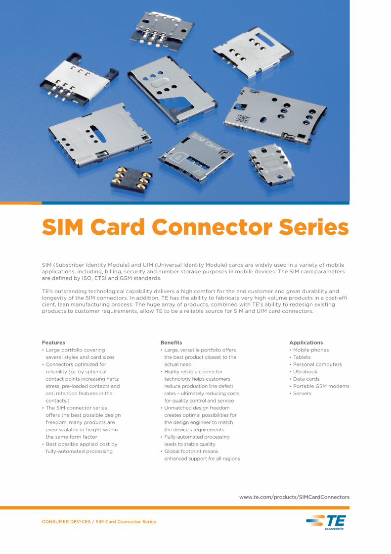
SIM Card Connector Series
Features Large portfolio covering •
several styles and card sizes Connectors optimized for •
reliability (i.e. by spherical contact points increasing hertz stress, pre-loaded contacts and anti retention features in the contacts.) The SIM connector series •
o�ers the best possible design freedom; many products are even scalable in height within the same form factor Best possible applied cost by •
fully-automated processing
Benefi ts Large, versatile portfolio o�ers •
the best product closest to the actual need Highly reliable connector •
technology helps customers reduce production line defect rates – ultimately reducing costs for quality control and service Unmatched design freedom •
creates optimal possibilities for the design engineer to match the device's requirements Fully-automated processing •
leads to stable quality Global footprint means •
enhanced support for all regions
ApplicationsMobile phones•
Tablets•
Personal computers•
Ultrabook•
Data cards•
Portable GSM modems•
Servers•
SIM (Subscriber Identity Module) and UIM (Universal Identity Module) cards are widely used in a variety of mobile applications, including, billing, security and number storage purposes in mobile devices. The SIM card parameters are defined by ISO, ETSI and GSM standards.
TE's outstanding technological capability delivers a high comfort for the end customer and great durability and longevity of the SIM connectors. In addition, TE has the ability to fabricate very high volume products in a cost-effi cient, lean manufacturing process. The huge array of products, combined with TE's ability to redesign existing products to customer requirements, allow TE to be a reliable source for SIM and UIM card connectors.
CONSUMER DEVICES / SIM Card Connector Series
www.te.com/products/SIMCardConnectors
CONSUMER DEVICES / SIM Card Connector Series
Variety of SIM Card Connectors Portfolio
PAGE 2
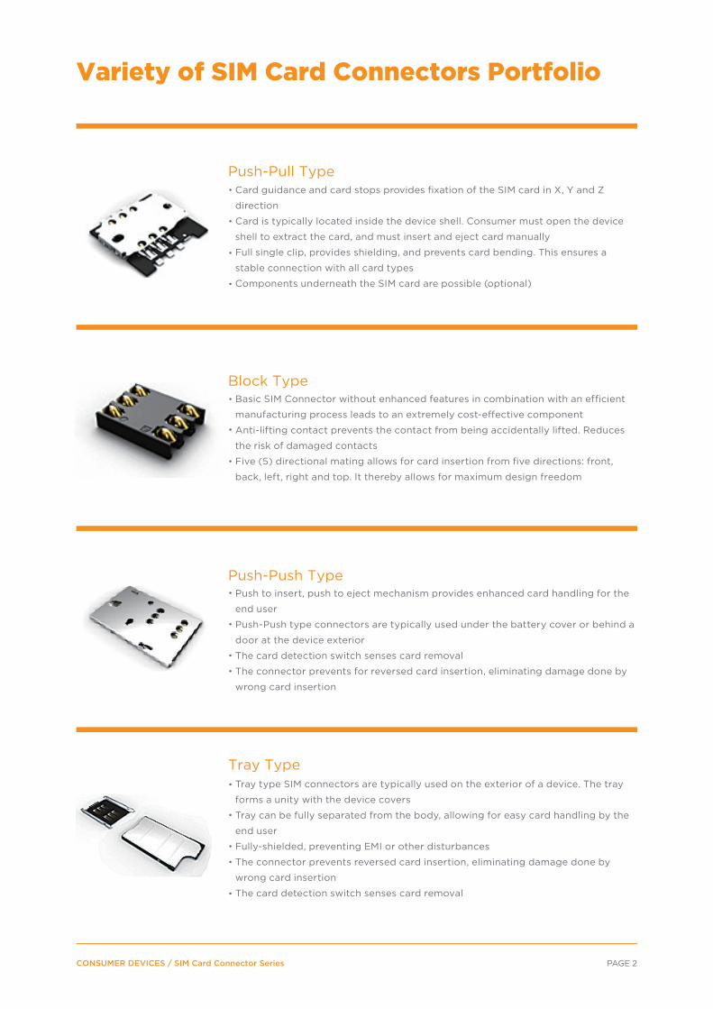
Push-Pull TypeCard guidance and card stops provides fi xation of the SIM card in X, Y and Z
direction
Card is typically located inside the device shell. Consumer must open the device
shell to extract the card, and must insert and eject card manually
Full single clip, provides shielding, and prevents card bending. This ensures a
stable connection with all card types
Components underneath the SIM card are possible (optional)
Block TypeBasic SIM Connector without enhanced features in combination with an efficient
manufacturing process leads to an extremely cost-e�ective component
Anti-lifting contact prevents the contact from being accidentally lifted. Reduces
the risk of damaged contacts
Five (5) directional mating allows for card insertion from five directions: front,
back, left, right and top. It thereby allows for maximum design freedom
Push-Push TypePush to insert, push to eject mechanism provides enhanced card handling for the
end user
Push-Push type connectors are typically used under the battery cover or behind a
door at the device exterior
The card detection switch senses card removal
The connector prevents for reversed card insertion, eliminating damage done by
wrong card insertion
Tray TypeTray type SIM connectors are typically used on the exterior of a device. The tray
forms a unity with the device covers
Tray can be fully separated from the body, allowing for easy card handling by the
end user
Fully-shielded, preventing EMI or other disturbances
The connector prevents reversed card insertion, eliminating damage done by
wrong card insertion
The card detection switch senses card removal

CONSUMER DEVICES / SIM Card Connector Series
Pus
h-P
ull T
ype
PictureP/N Height range
Length ×width Description Features and benefits Status
*-2042647-**-2042920-*
Side entry SIM connector LEFTSide entry SIM connector RIGHT
Super low profi le SIM with fl ange(big shield)
(dimensions:mm)
Connectors for Mini SIM (2FF) Cards
*-1551663-*
1981898-1
1932669-2
1551956-1
1932766-1
1932768-1
1.8 – 2.0
1.8 – 2.0
1.43
2.05
1.4
1.5
1.95
15.5 x 10
15.5 x 10
17.5 x 16.3
26.3 x 14.7
15.5 x 14.25
17.6 x 16.1
16.3 x 14.8
Scalable shielded SIM
Narrow shield version
Super low profile SIM
SIM 1.4mm height
SIM 1.5mm height
MPSH/India
MPSH/India
MP SH
MP SH
MP GD
MP GD
MP SH
Features- shielded- holes for additional components under the connector- test holes for automatic inline testing
Benefits- shield protects against radio interference- holes under the connector save space- test holes reduce applied costs
Features- fully shielded- test holes- super low height contact- super low height
Benefits- shield protects against radio interference- test holes reduce applied costs- can only be engaged from one side
Features- visible detection of wrong card insertion- chamfered housing- user friendly shield design- test holes
Benefits- prevents wrong card insertion- safe user handling- can remove card without tools- shield prevents EMI- inline testing reduces costs
Features- one clip type (bridge type) - shielded- holes under the connector- card stop and guide- preloaded contacts- test holes
Benefits- prevents card damage- shield prevents EMI, RF distortion and card bend- preloaded anti-lifting contacts protect card from abuse- mounting components under the connector saves space- automated testing reduces costs
Features- provides card stop- shielded- preloaded contacts- holes under the connector- test holes
Benefits- card stop prevents damage to the SIM card- shield prevents EMI, RF distortion and card bend- preloaded anti-lifting contacts protect card from abuse- mounting components under the connector saves space- automated testing reduces costs
PAGE 3P

CONSUMER DEVICES / SIM Card Connector Series
(dimensions:mm)
PictureP/N Height range
Length ×width Description Features and benefits Status
*-1705300-*
Connectors for Mini SIM (2FF) Cards
1.5 – 2.8 10 x 7.6 MP QD
Features- 5 insert directions - preloaded contacts- fits both standards (2FF and 3FF)
Benefits- smooth insertion for consumer- design flexibility
PAGE 4P
2134033-1
1.4 25.85 x 16.7
2134034-1
Blo
ck T
ype
5-Directional SIM connector
1981959-1
2174918-1
1.87
1.40
23.7 x 18.9
26 x 17
MP SH
MP GD
MP JP
MP JP
Features- push-push function - card detection switch- fully shielded- anti launch mechanism- test holes
Benefits- prevents inaccurate switch readings caused by common rough edges on cards- shield prevents EMI RF distortion and card bend- prevents wrong card insertion- prevents card going airborne when extracted- automated testing reduces costs
Features- push-push function allows SIM card ejection by connector itself- lower profile- dual slanted contacts - card detection switch
Benefits- easy to handle SIM card - low profile saves PCB space- dual slanted contacts provide strong mating force and avoid contact jam- card detection switch secures circuit design
Pus
h –
Pus
h Ty
pe
Tray
Typ
e
Push-push SIM connector
Push-push SIM, super low profile
Double contact metal tray
Double contact body assy
- tray can be fully separated from the body, allowing for easy card handling by the end user
CONSUMER DEVICES / SIM Card Connector Series
(dimensions:mm)
- push-push function allows SIM card ejection by connector itself to help the end customer handle SIM card easily - avoid card insertion with wrong direction, avoid card jamming issue- low profile saves space- dual slanted contacts provide strong mating force and avoid contact jam- card detection switch secures circuit design
PictureP/N Height range
Length ×width Description Features and benefits Status
2174803-2
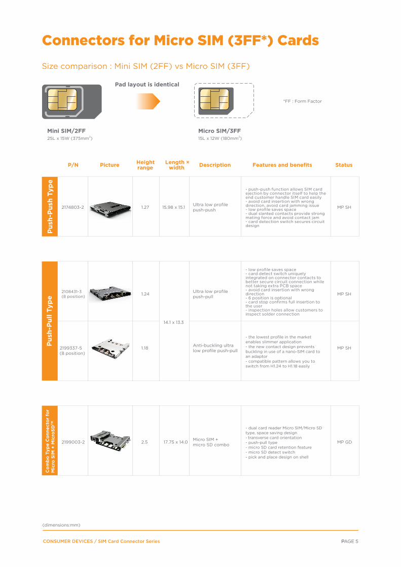
Connectors for Micro SIM (3FF*) Cards
15.98 x 15.1 MP SH
PAGE 5P
Pus
h-P
ush
Typ
e
1.27 Ultra low profile push-push
- low profile saves space- card detect switch uniquely integrated on connector contacts to better secure circuit connection while not taking extra PCB space- avoid card insertion with wrong direction- 6 position is optional- card stop confirms full insertion to the user- inspection holes allow customers to inspect solder connection
MP SH
Pus
h-P
ull T
ype
2108431-3(8 position)
14.1 x 13.3
1.24 Ultra low profile push-pull
- dual card reader Micro SIM/Micro SD type, space saving design- transverse card orientation- push-pull type- micro SD card retention feature- micro SD detect switch- pick and place design on shell
MP GD
Co
mb
o T
ype
Co
nnec
tor
for
Mic
ro S
IM +
Mic
roSD
TM
2199003-2 17.75 x 14.02.5 Micro SIM +micro SD combo
- the lowest profile in the market enables slimmer application- the new contact design prevents buckling in use of a nano-SIM card to an adaptor- compatible pattern allows you to switch from H1.24 to H1.18 easily
MP SH2199337-5 (8 position)
1.18 Anti-buckling ultra low profile push-pull
Size comparison : Mini SIM (2FF) vs Micro SIM (3FF)
*FF : Form Factor
Pad layout is identical
Mini SIM/2FF25L x 15W (375mm2)
Micro SIM/3FF15L x 12W (180mm2)
CONSUMER DEVICES / SIM Card Connector Series
Frequently Asked Questions
FOR MORE INFORMATION
TE Connectivity Technical Support Center+1 (800) 522-6752
Canada: +1 (905) 475-6222Mexico: +52 (0) 55-1106-0800Latin/South America: +54 (0) 11-4733-2200 Germany: +49 (0) 6251-133-1999
Part numbers in this brochure are RoHS Compliant*, unless marked otherwise.*as defined www.te.com/leadfree
USA: +44 (0) 800-267666France: +33 (0) 1-3420-8686Netherlands: +31 (0) 73-6246-999China: +86 (0) 400-820-6015
UK:
te.com
Question 1 How do I decide which type of SIM connector to choose?Answer 1
Question 4 When should I use a micro SIM connector?Answer 4When the device requires the use of a micro SIM card.
Question 5 What's the scalable height? Answer 5
The major di�erence in choosing between SIM connectors depends on the design of the customer device. Push-push or tray type SIM connectors allow users to extract the SIM card from the external portion of the device. Push-pull or block type connectors require users to open the back shell of the device and manually pull out the SIM card.
Question 2 What is the purpose of an 8 position SIM connector?Answer 2The extra two positions support an additional function like e-Pay.
The scalable height is found when the SIM card connector is scalable by a di�erent P/N, but the connector footprint stays the same. The benefit is enabling the customer to swap the product easily when a design change occurs, thereby reducing the lead-time of TTM (Time To Market), TTV (Time To Value) and design cost.
Question 3What is the benefit of dual-slanted contact performance?Answer 3The dual-slanted design prevents contact jam issues and creates a stronger mating performance, as demonstrated during the drop test.
©2014 TE Connectivity Ltd. family of companies. All Rights Reserved.
2-1773464-0 SPARKS 07/2014
TE Connectivity, TE connectivity (logo) and TE (logo) are trademarks. Other logos, product and/or company names might be trademarks of their respective
owners.
While TE has made every reasonable e�ort to ensure the accuracy of the information in this brochure, TE does not guarantee that it is error-free, nor does TE make any other representa-tion, warranty or guarantee that the information is accurate, correct, reliable or current. TE reserves the right to make any adjustments to the information contained herein at any time without notice. TE expressly disclaims all implied warranties regarding the information contained herein, including, but not limited to, any implied warranties of merchantability or fitness for a particular purpose. The dimensions in this catalog are for reference purposes only and are subject to change without notice. Specifications are subject to change without notice. Consult TE for the latest dimensions and design specifications.