signet 515 rotor-x paddlewheel flow sensorsfile.yizimg.com/343135/2010051810014892.pdf ordering...
TRANSCRIPT

Features• Operating range 0.3 to 6 m/s (1 to 20 ft/s)
• Wide turndown ratio of 20:1
• Highly repeatable output
• Simple, economical design
• Installs into pipe sizes DN15 to DN900
(½ to 36 in.)
• Self-powered/no external power required
• Test certificate included for -X0, -X1
• Chemically resistant materials
Applications• Pure Water Production• Filtration Systems• Chemical Production• Liquid Delivery Systems• Pump Protection• Scrubber Systems• Water Monitoring• Not suitable for gases
Signet 515 Rotor-X Paddlewheel Flow Sensors
Description
System Overview (For overview of Wet-Tap System, see 3519 product page)
Simple to install with time-honored reliable performance, Signet 515 Rotor-X Paddlewheel Flow Sensors are highly repeatable, rugged sensors that offer exceptional value with little or no maintenance. The output signal of the Model 515 is a sinusoidal frequency capable of driving a self-powered flowmeter (Model 3-5090). The wide dynamic flow range of 0.3 to 6 m/s (1 to 20 ft/s) allows the sensor to measure liquid flow rates in full pipes and can be used in low pressure systems.
StandardSensor
(with red cap)
IntegralSensor
* See Fittings section for more information.
Signet Fittings* (sold separately)
Signet Model 515 Integral Mount Flow Sensor
Signet Flow Instrument(sold separately)5075 81505090 85505500 89005600
Signet Flow Instrument (sold separately) 8150 8550
Signet Integral Adapter Kit (3-8051) (sold separately)
Signet Universal Adapter Kit (3-8050) (sold separately)
Signet Flow Instrument (sold separately) 8150 8550
Integral Mount Pipe, Tank, Wall Mount Panel Mount
Signet Model 515 Standard or Wet-Tap (not shown) Flow Sensor
Signet Model 515 Standard or Wet-Tap (not shown) Flow Sensor
The Model 515 sensors are offered in a variety of materials for a wide range of pipe sizes and insertion configurations. The many material choices including PP and PVDF make this model highly versatile and chemically compatible to many liquid process solutions. Sensors can be installed in up to DN900 (36 in.) pipes using Signet’s comprehensive line of custom fittings. These custom fittings, which include tees, saddles, and weldolets, seat the sensor to the proper insertion depth into the process flow. The sensors are also offered in configurations for wet-tap and intrinsically safe installation requirements.
Wet-TapSensor
FMAPPROVED
LEAD FREE
RoHSCOMPLIANT
Pb

www.gfsignet.com
Dimensions
26.7 mm/ 1.05 in.
-X0 thru -X2
-X0 = 104 mm (4.1 in.)-X1 = 137 mm (5.4 in.)-X2 = 213 mm (8.4 in.)
53.3 mm/ 2.1 in.
Pipe Range½ to 4 in.:5 to 8 in.:10 in. and up:
515 Standard Mount Sensor
515 Integral Mount Sensor shown with Transmitter (sold separately)
SpecificationsGeneral Operating Range: 0.3 to 6 m/s (1 to 20 ft/s) Pipe Size Range: DN15 to DN900 (½ to 36 in.)Linearity: ±1% of max. range @ 25 °C (77 °F)Repeatability: ±0.5% of max. range @ 25 °C (77 °F)Min. Reynolds Number Required: 4500
Wetted Materials • Sensor Body: Glass-filled PP (black) or PVDF (natural)• O-rings: FPM (std) optional EPR (EPDM) or FFPM• Rotor Pin: Titanium, Hastelloy-C or PVDF; optional Ceramic, Tantalum, or
Stainless Steel• Rotor: Black PVDF or Natural PVDF; optional Tefzel®, with or without
Fluoroloy G® sleeve
Electrical Frequency: 19.7 Hz per m/s nominal (6 Hz per ft/s); sinusoidal Amplitude: 3.3 V p/p per m/s nominal (1 V p/p per ft/s)Source Impedance: 8 KΩCable Type: 2-conductor twisted pair with shield, 22 AWGCable Length: 7.6 m (25 ft) can be extended up to 60 m
(200 ft) maximum
515 Wet-Tap Mount Sensor with 3519 Wet-Tap ValveSee more information on the 3519 Wet-Tap Valve, refer to the 3519 product page.
-P3 = 297 mm (11.7 in.)-P4 = 333 mm (13.1 in.)-P5 = 409 mm (16.1 in.)
26.7 mm (1.05 in.)
-P3 thru -P5
Pipe Range½ to 4 in.5 to 8 in.10 in. and up
Application Tips:• Use the Conduit Adapter Kit to protect
the cable-to-sensor connection when used in outdoor environments. See Accessories section for more information.
• Use a sleeved rotor in abrasive liquids to reduce wear.• Sensor plug can be used to plug
installation fitting after extraction of sensor from pipe.
102 mm (4.0 in.)
-Y0 or -Y1
-Y0 = 152mm (6.0 in.) -Y1 = 185mm (7.3 in.)
26.7 mm (1.05 in.)
96 mm (3.8 in.)
Pipe Range 0.5 to 4 in. 5 to 8 in.
Max. Temperature/Pressure RatingStandard and Integral Sensor• PP: 12.5 bar @ 20 °C, 1.7 bar @ 90 °C (180 psi @ 68 °F, 25 psi @ 194 °F)• PVDF: 14 bar @ 20 °C, 1.4 bar @ 100 °C (200 psi @ 68 °F, 20 psi @ 212 °F)Operating Temperature:• PP: -18 °C to 90 °C (0°F to 194 °F)• PVDF: -18 °C to 100 °C (0 °F to 212 °F)
Wet-Tap Sensor• PP: 7 bar @ 20 °C, 1.4 bar @ 66 °C (100 psi @ 68 °F, 20 psi @ 150 °F)Operating temperature: -18 °C to 66 °C (0 °F to 150 °F)Max. wet-tap sensor removal rating: 1.7 bar @ 22 °C (25 psi @ 72 °F)
See Temperature and Pressure Graphs for more information.
Shipping Weight P51530-X0 0.454 kg 1.00 lbP51530-X1 0.476 kg 1.04 lbP51530-X2 0.680 kg 1.50 lbP51530-X3 0.794 kg 1.75 lbP51530-X4 0.850 kg 1.87 lbP51530-X5 1 kg 2.20 lb3-8510-X0 0.23 kg .50 lb3-8510-X1 0.23 kg .50 lb
Standards and Approvals• FM Class I, II, III/Div. 1/groups A-G• RoHS compliant• Manufactured under ISO 9001 for Quality and ISO 14001 for Environmental Management
• For liquids containing ferrous particles, use Signet Magmeters.
• For systems with components of more than one material, the maximum temperature/pressure specification must always be referenced to the component with the lowest rating.
Please refer to Wiring, Installation, Accessories and Fittings sections for more information.

www.gfsignet.com
Ordering InformationModel 515 Standard Mount PaddlewheelWhen choosing this style of sensor, the instrument can be mounted nearby on a pipe or wall or in a remote location up to 60 m/200 ft (standard cable length is 7.6 m/25 ft) by connecting the sensor through a standard 3-8050-1 universal junction box. Use Signet fittings for proper seating of the sensor into the process flow.
Once an integral mount sensor is chosen, it can be mounted directly to a field mount transmitter by following these guidelines:a) Order the integral adapter kit 3-8051
(sold separately) to connect the sensor to an instrument.
b) Order a field mount transmitter (sold separately). The following part numbers are compatible: 3-8550-1, 3-8550-2, 3-8550-3, 3-8150-1.
Model 515 Standard Paddlewheel Flow Sensor
Model 515 Integral Mount Paddlewheel Flow Sensor
Model 515 Integral Mount PaddlewheelWhen choosing this style of sensor, the instrument is mounted directly onto the sensor for a local display. See Guideline below for instructions.
*Model 515Ordering Notes1) Most common part
number combinations shown. For all other combinations contact factory.
2) Other rotor and pin materials are available for purchase from the factory and can be easily replaced in the field. See Accessories section.
Guideline: Combining a 515 Integral mount flow sensor with an integrally mounted instrumentOption 1
c) Assembling the sensor with the integral adapter and instrument is quick and simple.
Option 2These parts can also be ordered as anassembled part. See page 74 “Integral Mount” for more information.
Sensor Part Number P51530 Flow Sensor for use with remote mount instrument
Body/Rotor/Pin Material-Choose One*- H Polypropylene/Black PVDF/Hastelloy-C- P Polypropylene/Black PVDF/Titanium- S Polypropylene/Black PVDF/Natural PVDF- T Natural PVDF/Natural PVDF/Natural PVDF- V Natural PVDF/Natural PVDF/Hastelloy-C
Pipe Size - Choose One0 ½ to 4 in.1 5 to 8 in.2 10 to 36 in.
P51530 - P 0 Example Part Number
Sensor Part Number 3-8510 Flow Sensor for integral mounting on the 8150 or 8550 instrument
using the 3-8051 adapter (instrument and adapter sold separately)Body/Rotor/Pin Material-Choose One*- P Polypropylene/Black PVDF/Titanium- T Natural PVDF/Natural PVDF/Natural PVDF**- V Natural PVDF/Natural PVDF/Hastelloy-C**
Pipe Size - Choose One0 ½ to 4 in.1 5 to 8 in. (PP only)
3-8510 - P 0 Example Part Number
**PVDF available ½ in. to 4 in. only
Mfr. Part No.* Code Mfr. Part No.* CodeP51530-H0 198 801 659 P51530-T0 198 801 663P51530-P0 198 801 620 P51530-T1 198 801 664P51530-P1 198 801 621 P51530-V0 198 801 623P51530-P2 198 801 622 P51530-V1 198 801 624P51530-S0 198 801 661 P51530-V2 198 801 625
Mfr. Part No.* Code Mfr. Part No.* Code3-8510-P0 198 864 504 3-8510-T0 159 000 6223-8510-P1 198 864 505 3-8510-V0 198 864 506

Ordering Information (continued)
Accessories and Replacement Parts
Signet 515 Wet-Tap Sensor with the 3519 Wet-Tap Valve Model 515 Wet-Tap Mount Paddlewheel Flow Sensor
When choosing this style of sensor, the instrument can be mounted nearby on a pipe or wall or in a remote location up to 60 m (200 ft) by connecting the sensor through a standard 3-8050-1 universal junction box. Standard cable length is 7.6 m (25 ft). This style of sensor uses the 3519 Wet-Tap valve only (see individual product page for more information).
*Model 515Ordering Notes1) Other rotor and pin
materials are available for purchase from the factory and can be easily replaced in the field. See Accessories section.
Rotor
Rotor Pin
Sensor Cap
Sensor Plug
ConduitAdapter Kit
Guideline: Combining a 515 Wet-Tap Sensor with a 3519 Wet-Tap Valvea) Sensor can be mounted in a 3519 Wet-Tap Valve (sold separately)b) Assembling a sensor with a 3519 Wet-Tap valve is quick and simple.
These parts can also be ordered as complete assemblies. See 3519 product page.
Sensor Part Number P51530 Flow Sensor for wet-tap mounting with the 3519 Wet-Tap Valve (sold separately)
Body/Rotor/Pin Material*- P Polypropylene/Black PVDF/Titanium
Pipe Size - Choose One3 ½ to 4 in.4 5 to 8 in.5 10 to 36 in.
P51530 - P 3 Example Part Number
Mfr. Part No. Code DescriptionRotors M1538-2 198 801 181 Rotor, PVDF BlackP51547-3 159 000 474 Rotor, PVDF NaturalM1538-4 198 820 018 Rotor, Tefzel®
P51550-3 198 820 043 Rotor and pin (matched set), PVDF Natural3-0515.322-1 198 820 059 Sleeved rotor, PVDF Black3-0515.322-2 198 820 060 Sleeved rotor, PVDF Natural3-0515.322-3 198 820 017 Sleeved rotor, Tefzel®
Rotor PinsM1546-1 198 801 182 Pin, TitaniumM1546-2 198 801 183 Pin, Hastelloy-CM1546-3 198 820 014 Pin, TantalumM1546-4 198 820 015 Pin, Stainless SteelP51550-3 198 820 043 Rotor and pin, PVDF NaturalP51545 198 820 016 Pin, CeramicO-Rings1220-0021 198 801 186 O-ring, FPM (2 required per sensor)1224-0021 198 820 006 O-ring, EPR (EPDM) (2 required per sensor)1228-0021 198 820 007 O-ring, FFPM (2 required per sensor)MiscellaneousP31536 198 840 201 Sensor plug, PolypropyleneP31542 198 801 630 Sensor cap, RedP31934 159 000 466 Conduit capP51589 159 000 476 Conduit adapter kit 5523-0222 159 000 392 Cable (per foot), 2 cond. w/shield, 22 AWG3-8051 159 000 187 Transmitter integral adapter (for use with 8510 and
8512) (see system overview for graphics) 6400-9001 159 001 466 Intrinsic safety barriers (2 required)3-8051-1 159 000 753 Universal junction box
Mfr. Part No.* CodeP51530-P3 198 840 310P51530-P4 198 840 311P51530-P5 198 840 312
-P3 = 297 mm (11.7 in.)-P4 = 333 mm (13.1 in.)-P5 = 409 mm (16.1 in.)
26.7 mm (1.05 in.)
-P3 thru -P5
Pipe Range½ to 4 in.5 to 8 in.10 in. and up
3-0515.099 Rev A (01/10) © Georg Fischer Signet LLC3401 Aerojet Avenue, El Monte, CA 91731-2882 U.S.A. • Tel. (626) 571-2770 • Fax (626) 573-2057 • www.gfsignet.com • e-mail: [email protected] subject to change without notice. All rights reserved. All corporate names and trademarks stated herein are the property of their respective companies.

1. To remove the rotor, insert a small screwdriver between the rotor and the sensor ear.
2. Twist the screwdriver blade to fl ex the sensor ear outward enough to remove one end of the rotor/shaft assembly. DO NOT fl ex the ear any more than necessary! If it breaks, the sensor cannot be repaired.
3. Install the new rotor and shaft assembly by inserting one end into the hole in the sensor ear, then fl ex the opposite sensor ear back enough to slip new rotor and shaft into place.
Signet Rotor Replacement SheetAustauschanleitung für den Signet Sensor RotorSignet Remplacement du RotorCambio del rotor Signet
Signet Metal Flow Sensor Rotor Replacement Instructions
3-0515.092-1 Rev. D 9/09 E G F S
*3-0515.092-1*
Note: Always replace both Rotor and Shaft together!
Signet Plastic Flow Sensor Rotor/Shaft Replacement Instructions
1. With a small pair of needle-nose pliers, fi rmly grip the center of the rotor pin (axle) and with a twisting motion, bend the rotor pin into an "S" shape. This should pull the ends of the pin out of the retainers and free the rotor assembly.
2. Remove rotor pin retainer from each side by gently tapping it inwards using a punch. Install a new retainer into the sensor body with its rotor pin clearance hole inward. Only install one retainer at this time.
Rotor Pin
Existing
Retainer New
Bearings
Rotor
Assembly
3. Insert the new rotor assembly and bearings into the rotor housing of the sensor and place the new rotor pin (axle) through the open end of the rotor housing, through the rotor and bearings, and into the previously installed retainer.
4. Using a vise or C-clamp, press the second retainer into the hole in the sensor body while lining up the rotor pin with the center of the retainer hole.
Note: A hammer and center punch can also be used if a clamp or vice is not available.
PunchRetainer
Rotor Pin

2
1. Zum Austausch des Rotors einen kleinen Schraubendreher zwischen den Rotor und die Rotorhalterung des Sensors bringen.
2. Die Klinge des Schraubendrehers drehen und die Halterung vorsichtig nach außen biegen; den Rotor und die Achse an einem Ende herausnehmen. Die Halterung nicht mehr als nötig biegen! Sollte sie abbrechen, gibt es keine Möglichkeit den Sensor zu reparieren.
3. Um den neuen Rotor und die neue Achse einzubauen setzt man den Rotor in einer Seite der Halterung ein und biegt die gegenüberliegende Seite vorsichtig und gerade weit genug zurück, um das andere Ende des Rotors und Achse einzusetzen.
Anmerkung: Ersetzen Sie den Rotor und die Achse!
Anleitung zum Austausch des Schaufelrades
Austauschanleitung für den Signet Kuststoff Sensor Rotor/Achse
1. Halten Sie den Rotorschaft (Achse) mit einer kleinen Spitzzange in der Mitte fest und verdrehen Sie den Stift zu einer “S”-Form. Dadurch werden die Enden des Stiftes aus den Lagerhülsen gehoben und das Rotorbauteil freigelegt.
2. Entfernen Sie an jeder Seite die Lagerhülse, indem Sie sie mit einem Durchschlag vorsichtig nach innen treiben. Bauen Sie einen neuen Rotor so ein, daß das Schaftabstandsloch nach innen zeigt. Setzen Sie zunächst nur eine Lagerhülse ein.
DornHalterung
Rotorstift
3. Setzen Sie das neue Rotorbauteil und neue Lager in das Rotorgehäuse des Sensors ein und schieben Sie den neuen Rotorschaft (Achse) durch das offene Ende des Rotorgehäuses, den Rotor und die Lager in die vorher installierte Lagerhülse.
4. Einen Schraubstock oder eine Schraubzwinge verwenden und den zweiten Halter in die Öffnung im Sensorkörper drücken, während die Rotorachse auf die Mitte der Halteröffnung ausgerichtet wird.
Hinweis: Alternativ kann ein Hammer und Körner verwendet werden, wenn kein Schraubstock und keine Schraubzwinge zur Verfügung stehen.
Rotorstift
Vorhandene
Halterung Neue
Lager
Rotorbaugruppe

3
1. Pour retirer le rotor, insérer un petit tourne-vis entre le rotor et l'oreille du capteur.
2. Tourner la lame du tourne-vis de façon à fl échir vers l'extérieur l'oreille afi n de retirer une extrémité du rotor ainsi que d'axe. Ne pas fl échir l'oreille plus qu' il n'est nécessaire! Si elle venait à casser, il n' y aurait aucun moyen de réparer le capteur.
3. Le nouveau rotor et axe peuvent être installé en insérant une oreille dans le trou, puis en fl échissant l'oreille opposé suffi samment en arrière pour pouvoir glisser l'autre extrémité en place.
Attention! Le rotor/axe doivent toujours être remplacés ensemble.
Instructions pour le remplacement de la roue à palettes Signet metall
Instructions pour le remplacement du rotor/d'axe du capteur Signet Plastique
3. Poser le rotor et les paliers neufs dans le boîtier du rotor du capteur, et poser l’axe de rotor neuf (dans l’extrémité ouverte du boîtier du rotor) dans le rotor et les paliers, puis dans le dispositif de retenue déjà installé.
4. À l'aide d'un étau ou d'un serre-joint en C, appuyer la seconde retenue dans le trou du corps du capteur tout en alignant l'axe du rotor sur le centre du trou de retenue.
Remarque : Il est également possible d'utiliser un marteau ou un poinçon en l'absence de serre-joint ou d'étau.
1. Avec une pince plate à becs pointus, saisir fermement le centre de l’axe du rotor, tourner la pince pour donner à l’axe du rotor la forme d’un S. Cette opération devrait sortir l’axe de ses dispositifs de retenue et permettre de libérer le rotor.
2. Marteler doucement à l´aide d´un pointeau. Remettre un nouveau dispositif de retenue en place avec son trou de dégagement d’axe de rotor vers l´intérieur. Installer un seul dispositif de retenue à ce stade.
Tige du rotor
GoupilleNouveau
palier
Rotor
PoinèonGoupille
Tige du rotor

Georg Fischer Signet LLC, 3401 Aerojet Avenue, El Monte, CA 91731-2882 U.S.A. • Tel. (626) 571-2770 • Fax (626) 573-2057For Worldwide Sales and Service, visit our website: gfsignet.com • Or call (in the U.S.): (800) 854-4090For the most up-to date information, please refer to our website at www.gfsignet.com
3-0515.092-1 Rev. D 9/09 E G F S © Georg Fischer Signet LLC 2009
1. Para desmontar el rotor, inserte un destornillador pequeño entre el rotor y el asidero del sensor.
2. Gire la pala del destornillador para doblar el asidero del sensor hacia afuera, lo sufi ciente como para retirar un extremo del conjunto rotor-eje. ¡NO doble el asidero más de lo necesario! Si se llega a romper, no se podrá reparar el sensor.
3. Instale el nuevo juego de rotor y eje insertando un extremo en el agujero del asidero del sensor, y seguidamente doblando hacia atrás el asidero opuesto, lo sufi ciente como para que se pueda deslizar el nuevo juego de rotor y eje en su lugar.
Nota: ¡Cambie siempre el rotor y el eje al mismo tiempo!
Instrucciones para el cambio del rotor del sensor de acero inoxidable Signet
Instrucciones para el cambio del conjunto rotor y eje del sensor de fl ujo del plástico Signet
3. Inserte el nuevo conjunto del rotor y los cojinetes en el cuerpo del rotor que se encuentra en el sensor y coloque un nuevo eje de rotor a través del extremo abierto del cuerpo del rotor, a través del rotor y los cojinetes y en el retenedor instalado previamente.
4. El uso de un tornillo de banco o una abrazadera en “C”, encaje a presión el segundo retenedor en el agujero del cuerpo del sensor mientras alinea el pasador del rotor con el centro del agujero del retenedor.
Nota: También se puede usar un martillo y un punzón central si no se dispone de una abrazadera o un tornillo de banco
1. Con un pequeño par de pinzas afi ladas, sujete fi rmemente el centro del eje del rotor (eje) y con un movimiento de torsión, doble el eje del rotor en una forma de “S”. Esta acción extraerá los extremos del eje de los retenedores y liberará el conjunto del rotor.
2. Saque el retenedor de cada lado dando un golpecito suave hacia adentro con un troquel. Instale un nuevo retenedor con el orifi cio de pase del eje del rotor hacia adentro. Instale solamente un retenedor en este momento.
Eje del rotor
Retenedor existente Cojinetes
nuevos
Conjunto del rotor
troquelretenedor
eje del rotor

Signet 525 Metalex Paddlewheel Flow Sensor
Features• For up to 103 bar
(1500 psi @ safety factor 1.5) pressure
• For up to 149 °C (300 °F) temperature
• DN15 to DN300 (½ to 12 in.) pipe range
• Simple installation
• Self-powered/no external power required
• 316 SS body (1.4401)
• Tungsten Carbide or SS shaft
• 7.6 m (25 ft) cable included
• FM approved
• Operating range 0.5 to 6m/s (1.6 to 20 ft/s)
Applications
• Boiler Feedwater Monitoring• HVAC Systems• Chemical Transport• Heat Exchangers• Reverse Osmosis• Cooling systems• Not Suitable for Gases
DescriptionThe Signet 525 Metalex Paddlewheel Flow Sensor combines stainless steel construction with insertion paddlewheel technology. The result is a highly reliable sensor suitable for operation at extreme pressures and temperatures. The Tungsten Carbide shaft and Rulon® B (Fluoroloy B/PTFE) bearing provides excellent wear resistance for extended service.
A comprehensive fitting program allows installation in steel lines with the mini-block for small diameters, and either the mini-tap or saddle for pipes up to DN300 (12 in.). The self-generating output signal allows use with the battery operated flow totalizer 8150.
System Overview
* See Fittings section for more information.
*Signet Metalex Fitting (sold separately)
Signet Flow Instrument(sold separately)5075 81505500 85505600 8900
Signet Universal Adapter Kit (3-8050) (sold separately)
Signet Flow Instrument (sold separately) 8150 8550
Pipe, Tank, Wall Mount Panel Mount
Signet Model 525 Metalex Flow Sensor
FMAPPROVED
LEAD FREE
RoHSCOMPLIANT
Pb

Specifications
Ordering Information
DimensionsGeneralOperating Range: 0.5 to 6 m/s (1.6 to 20 ft/s)Pipe Size Range: DN15 to DN300 (½ to 12 in.)Linearity: ±1% of max. range @ 25 °C (77 °F)Repeatability: ±0.5% of max. range @ 25 °C (77 °F)Min. Reynolds Number Required: 4500Wetted MaterialsSensor Body: 316 SS (ACI type CF-8M per ASTM A351),
DIN 17440Rotor Material: CB7Cu-1 AlloyRotor Pin: Tungsten Carbide GRP 1 or
316 stainless steelRetainers (2): 316 stainless steel (1.4401)Rotor Bearings (2): Rulon® B (Fluoroloy/ PTFE)Gasket: KLINGER®sil C-4401 (supplied with fitting)
Electrical Frequency: 12 Hz per ft/s nominal, Amplitude: 5 to 8 mV p-p per HzSource Impedance: 11.6 KΩCable Length: 7.6 m (25 ft), can be extended up to 60 m
(200 ft)
Accessories and Replacements Parts
*Model 525 Ordering Notes1) Each sensor option is
used with a different fitting based on pipe size.
2) Fittings must be ordered separately.
3) See fittings section for more information.
Cable Type: Cable (per foot) 2 cond. w/shield, 22 AWG
Max. Temperature/Pressure Rating• Socket Weld or Weld-On Mini-Tap
fittings: 103 bar (1500 psi @ safety factor 1.5)
@ 149 °C (300 °F) • Strap-on Saddle fitting: 21 bar (300 psi) @ 66 °C (150 °F)Operating Temperature: -18 °C to 149 °C (0 °F to 300 °F)
See Temperature and Pressure graphs for more information.
Shipping Weight P525-1/-1S 0.723 kg 1.6 lbP525-2/-2S 0.774 kg 1.7 lbP525-3/-3S 0.923 kg 2.0 lb
Standards and Approvals• FM Class I (Group A, B, C, D), II
(Group E,F,G), III, Division 1 (Groups A-G)• RoHS compliant• Manufactured under ISO 9001
for Quality and ISO 14001 for Environmental Management
retainer rotor pin retainer
bearing bearing
rotor
Rotor Kit
Electrical (continued)
Application Tips• Use the Conduit
Adapter Kit to protect the cable-to-sensor connection when used in outdoor environments. See Accessories section.
• Use the Socket Weld or Weld-on Mini-Tap fittings for sensor installation in pressures up to 1500 psi (103 bar).
• The 525 can be used in intrinsically safe areas using an approved barrier between the sensor and instrument.
7.6 m/25 ftcable included
SIGNET
-1 = 38.4 mm (1½ in.)
-2 = 63.5 mm (2½ in.)
-3 = 114.3 mm (4½ in.)
27 mm (1.06 in.) dia
Sensor Part Number P525 Metalex Flow sensor for high pressures and temperatures
Sensor Style-1 used with ½ to 1 inch socket-weld mini-tap fittings**-2 used with 1¼ to 12 inch weld-on mini-tap fittings**-3 used with 2 to 12 inch strap-on saddle fittings**
Rotor Pin Material- Tungsten CarbideS 316 Stainless Steel
P525 -1 Example Part Number**See Fittings section.
Please refer to Wiring, Installation, and Accessories sections for more information.
Mfr. Part No. Code DescriptionP52509 198 801 501 Rotor kit (rotors, stainless steel pin, bearings, retainers)P52509-2 159 000 480 Rotor kit (rotors, tungsten carbide pin, bearings, retainers)P52504-1 198 801 500 Rotor pin, Stainless Steel (1.4401)P52504-2 198 820 023 Rotor pin, Tungsten CarbideP52618 159 000 493 GasketP52503 198 820 013 Bearing, Rulon® B (Fluoroloy/PTFE)P52527 159 000 481 Retainers, Stainless SteelP52628 159 000 504 Fitting cap kit (cap and gasket)P51589 159 000 476 Conduit adapter kit5523-3222 159 000 393 Cable (per foot) 2 cond. w/shield, 22 AWG6402-9001 159 001 486 Intrinsic safety barrier (2 required)
Mfr. Part No.* Code Mfr. Part No.* CodeP525-1 198 801 494 P525-1S 159 000 963P525-2 198 801 495 P525-2S 159 000 964P525-3 198 801 496 P525-3S 159 000 965
3-0525.099 Rev A (01/10) © Georg Fischer Signet LLC3401 Aerojet Avenue, El Monte, CA 91731-2882 U.S.A. • Tel. (626) 571-2770 • Fax (626) 573-2057 • www.gfsignet.com • e-mail: [email protected] subject to change without notice. All rights reserved. All corporate names and trademarks stated herein are the property of their respective companies.

Signet 2000 MicroFlow Rotor Sensor
Features
• Operating range 0.11 to 12.11 lpm (0.03 to 3.2 U.S. gpm)
• Simple mounting
• ¼ in. NPT or ISO threads for simple pipe or tubing connection
• Measures opaque and transparent liquids
• Low pressure drop
• Standard cable 7.6 m (25 ft)
Applications
• Coolant Flow• Dosing• Batch Dispensing• Not recommended for
Strong Oxidizers
System Overview
Signet Flow Instrument(sold separately)5075 85505500 89005600 Signet Universal
Adapter Kit (3-8050) (sold separately)
Signet Flow Instrument(sold separately)8550
Pipe, Tank, Wall MountPanel Mount
Signet 2000 Flow Sensor
Flexible tubing or rigid pipe(customer supplied)
DescriptionThe Signet 2000 MicroFlow Rotor Sensor is constructed of Polyphenylene Sulfide (PPS) which provides high material strength. The 2000 offers two flow ranges starting at 0.11 or 1.13 lpm (0.03 or 0.3 gpm), for clean process liquids, regardless of fluid color or opacity.
This sensor can be connected to flexible tubing or rigid pipe, and uses standard hardware for mounting. Only one moving part and a low pressure drop across the sensor reduces operating costs and maintenance requirements.

SpecificationsDimensions
100 mm (3.94 in.)
Mounting tabs for metric M3 or standard #6 screws on 68 mm(2.68 in.) bolt circle
Top View
36 mm (1.42 in.)
81 mm(3.2 in.)
Side View
GeneralOperating Range:• -11 & -12 version: 0.11 to 2.6 lpm (0.03 to 0.7 U.S. gpm)• -21 & -22 version: 1.13 to 12.11 lpm (0.3 to 3.2 U.S. gpm) Linearity: ±1.2% of full rangeRepeatability: ± 0.5% of full rangeConnections: ¼ in. NPT (male) or ISO 7/1 - R1/4 (male)
Wetted Materials • Sensor body and cover: 40% glass filled Polyphenylene Sulfide
(PPS)• Rotor: PEEK™, natural, unfilled• Cover O-ring: FPM
ElectricalPower: 5 to 24 VDC ±10%, regulated, 10 mA max.Output Type: Open-collector, sinking, 10 mA max.Cable Length: 7.6 m (25 ft), can be extended
up to 300 m (1000 ft) Cable Type: 2-conductor twisted pair w/shield, 22 AWG
Max. Temperature/Pressure Rating0 °C to 80 °C @ 5.5 bar max.(32 °F to 176 °F @ 80 psi max.)
See Temperature and Pressure Graphsfor more information
Shipping Weight 0.3 kg 0.7 lb
Standards and Approvals• CE• Manufactured under ISO 9001
for Quality and ISO 14001 for Environmental Management
Ordering Information
Accessories and Replacement Parts
Application Tips• For use in clean fluids
- no suspended solids.• Use the mounting tabs
to secure the sensor to a flat surface, ±30°.
• Verify chemical compatibility before installation.
Cover Removed
Sensor Part Number 3-2000 MicroFlow rotor flow sensor
Flow Range1 Low flow, 0.11 to 2.61 lpm (0.03 to 0.7 gpm)2 High flow, 1.13 to 12.11 lpm (0.3 to 3.2 gpm)
End Fittings1 ¼ NPT threads2 ISO 7/1-R1/4 threads
3-2000 -1 1 Example Part Number
Please refer to Wiring, Installation, and Accessories sections for more information.
Mfr. Part No. Code Description3-2000.390 159 000 248 Replacement rotor kit1220-0029 198 820 049 Cover O-ring2450-0620 198 820 051 Cover screw5523-0222 159 000 392 Cable (per foot), 2 cond. w/shield, 22 AWG3-8050-1 159 000 753 Universal junction box
Mfr. Part No. Code Mfr. Part No. Code3-2000-11 198 822 000 3-2000-21 198 822 0023-2000-12 198 822 001 3-2000-22 198 822 003
3-2000.099 Rev C (01/10) © Georg Fischer Signet LLC3401 Aerojet Avenue, El Monte, CA 91731-2882 U.S.A. • Tel. (626) 571-2770 • Fax (626) 573-2057 • www.gfsignet.com • e-mail: [email protected] subject to change without notice. All rights reserved. All corporate names and trademarks stated herein are the property of their respective companies.

Signet 2100 Turbine Flow SensorFeatures• Operating range of 0.38 to 38 lpm (0.10 to 10 U.S. gpm)
• Non-magnetic turbine
• Union ends for various connector types
• End connector kits for rigid or flexible tubing or DN15 (½ in.) pipe
• PVDF & ceramic wetted parts provide superior chemical compatibility
• For use with both clear and opaque fluids
• Small and compact design
• 4.6 m (15 ft) cable
• Features removable electronics that installs from either side of the sensor
• Sensor mounts at any angle
Applications• Chemical Addition• Textile dyeing• High-purity Chemical
Dispensing• Water Addition• Fertigation• Dosing• Pump Protection• Not suitable for gases
along with removable NEMA 4X electronics allow for easy assembly and field replaceability. The 2100 can be used with DN8 (¼ in.), DN10 (3/8 in.), DN15 (½ in.) tubing, or DN15 (½ in.) piping for simple installation. End connections are available in PVDF for hose barbs, fusion socket or IR/butt fusion, and in PVC for socket or NPT thread.
DescriptionEngineered specifically for small pipe diameter applications, the Signet 2100 Turbine Flow Sensor provides accurate readings in two flow ranges: 0.3 to 3.8 lpm and 3 to 38 lpm (0.1 to 1 gpm and 0.8 to 10 gpm).
The injection-molded PVDF body and ceramic bearings provide excellent chemical compatibility and long service in dosing and batching applications. Union piping and tubing connections
System Overview
Panel Mount Pipe, Tank, Wall Mount Signet Flow Instrument(sold separately)5075 85505500 89005600
Signet Flow Instrument (sold separately) 8550
Signet UniversalAdapter Kit (3-8050)(sold separately)
Signet 2100 Flow Sensor
Fusion, threaded or solvent socket connectors for DN15 (1/2 in.) pipe
Hose barb connectors for DN8, DN10, or DN15 (1/4 in., 3/8 in. or 1/2 in.) flexible tubing
End Connector options
LEAD FREE
RoHSCOMPLIANT
Pb

SpecificationsDimensionsGeneralOperating Range: • -L = 0.38 to 3.8 lpm (0.10 to 1 U.S. gpm)• -H = 3 to 38 lpm (0.8 to 10 U.S. gpm)
Linearity: ±3% of readingRepeatability: ±0.5% of readingPipe size range: DN15 (½ in.)Hose size: DN8 (¼ in.), DN10 (3/8 in.), DN15 (½ in.)
Wetted MaterialsSensor Body/Rotor: PVDFShaft/Bearings: Ceramic O-rings: -1 = FPM, -2 = EPR (EPDM)Electronics: PBT (polybutylene terephthlate)
EVA (ethylene vinyl acetate)
ElectricalPower: 5 to 24 VDC ±10%, regulated, 1.5 mA max. Reverse polarity protected
Electrical (continued)Output: Open collector, sinking, max 30 mACable Length: 4.6 m (15 ft) can be
extended up to 300 m (1000 ft)Cable Type: PVC jacketed, 2 conductor twisted pair with shield (22 AWG)
Max. Temperature/Pressure Rating 16 bar @ 20 °C, 9.3 bar @ 70 °C (232 psi @ 68 °F, 130 psi @ 158 °F)Operating Temperature: -20 °C to 70 °C (-4 °F to 158 °F)Storage Temperature: -15 °C to 80 °C (5 °F to 176 °F)
See Temperature and Pressure graphs
Shipping Weight 0.15 kg 0.33 lb
Standards and Approvals• CE• RoHS compliant• Manufactured under ISO 9001
for Quality and ISO 14001 for Environmental ManagementOrdering Information
Accessories and Replacement Parts
l
L
l = 64 mm (2½ in.)
L = overall length All sockets: 102 mm (4 in.)Butt fusion/IR: 170 mm (6.7 in.)1/4 in. Barb: 124 mm (4.9 in.)3/8 in. Barb: 127 mm (5 in.)1/2 in. Barb: 132 mm (5.2 in.)
Please refer to Wiring, Installation, and Accessories sections for more information.
Electronics module
Sensor Part Number 3-2100 Turbine flow sensor, PVDF body and rotor, for use with various end-connectors
O-ring Material - Choose One-1 FPM-2 EPR (EPDM)
Flow RangeL low, 0.38 to 3.8 lpm (0.10 to 1 gpm)H high, 3 to 38 lpm (0.8 to 10 gpm)
3-2100 -1 L Example Part Number*Note: To install this flow sensor, end fittings must be installed on both ends of the sensor. See selection below
Fitting Part Number 3-2100 End fitting for Model 2100 sensor
Type of End Fitting-31 Hose barb connector kit, PVDF, ½ inch (1-hose barb and 1-ring nut)-32 Hose barb connector kit, PVDF, 3/8 inch (1-hose barb and 1-ring nut)-33 Hose barb connector kit, PVDF, ¼ inch (1-hose barb and 1-ring nut)-34 Fusion socket connector, PVDF, DN15 ½ inch (1-fusion socket and 1 ring nut)-35 Butt Fusion/IR connector kit, PVDF, DN15 ½ inch (1-IR socket and 1 ring nut)-36 Metric socket connector kit, PVC, ½ inch (1-solvent socket and 1 ring nut)-37 SCH 80 socket connector kit, PVC, ½ inch (1-solvent socket and 1 ring nut)-38 NPT thread socket connector kit, PVC, ½ inch (1-threaded socket and 1 ring nut)
3-2100 -33 Example Part Number
Mfr. Part No. Code Description1220-0018 159 000 019 O-rings FPM (2 required per sensor)1224-0018 159 000 020 O-rings EPR (EPDM) (2 required per sensor)3-2100.390-1L 159 000 015 Turbine Lo Flow with FPM O-rings (replacement body)3-2100.390-1H 159 000 016 Turbine Hi Flow with FPM O-rings (replacement body)3-2100.390-2L 159 000 017 Turbine Lo Flow with EPR (EPDM) O-rings (replacement body)3-2100.390-2H 159 000 018 Turbine Hi Flow with EPR (EPDM) O-rings (replacement body)3-2100.390 159 000 014 Electronics Module with 15 ft (4.6 m) cable3-8050-1 159 000 753 Universal junction box
Mfr. Part No. Code Mfr. Part No. Code3-2100-1L 159 000 001 3-2100-34 159 000 0083-2100-2L 159 000 003 3-2100-35 159 000 0093-2100-1H 159 000 002 3-2100-36 159 000 0103-2100-2H 159 000 004 3-2100-37 159 000 0113-2100-31 159 000 005 3-2100-38 159 000 0123-2100-32 159 000 0063-2100-33 159 000 007
D
Socket
Hose barb
O-ring
Application Tips• All socket and hose barb connector kits are
sold individually. Two kits are required for each sensor.
• Mount at any angle.• Junction block, 3-8050-1 recommended
if standard cable is extended to maximum 300 m (1000 ft)
3-2100.099 Rev A (01/10) © Georg Fischer Signet LLC3401 Aerojet Avenue, El Monte, CA 91731-2882 U.S.A. • Tel. (626) 571-2770 • Fax (626) 573-2057 • www.gfsignet.com • e-mail: [email protected] subject to change without notice. All rights reserved. All corporate names and trademarks stated herein are the property of their respective companies.

Signet 2507 Mini Flow Rotor SensorFeatures
• Operating range 400 to 12,000 ml/m (0.1 to
3.2 U.S. gpm)
• Detachable signal connector for easy servicing
• Simple installation with a G 1/4 in. (¼ in. NPT) threaded
connection
• Standard 7.6 m (25 ft) cable
• PVDF construction
• Compact assembly
Applications
• Fluid Dispensing• Laboratory and Clinical
Wet Benches• Chemical Dosing• Batch Processes
DescriptionThe Signet 2507 Mini Flow Rotor Sensor contains a free-running rotor that is driven by the fluid flow. Within the given measurement range, the rotational speed of the rotor is proportional to the fluid flow rate.
System Overview
Signet Pipe Fitting Adapters (two included)Used to convert the sensor's G1/4 in.straight threads into 1/4 in. NPT threads
Signet2507 Mini Flow Sensor
Signet Flow Instrument(sold separately)5075 85505500 89005600 Signet Universal
Adapter Kit (3-8050) (sold separately)
Signet Flow Instrument(sold separately)8550
Pipe, Tank, Wall MountPanel Mount
Magnets built into the rotor trigger an electronic switch in the top of the sensor creating a square-wave output. Both opaque and transparent fluids can be measured with kinematic viscosities between 0.2 to 20.0 centistokes.
LEAD FREE
RoHSCOMPLIANT
Pb

SpecificationsDimensions95 mm/3.74 in.
FLOW
65 mm/2.6 in.
68 mm/2.7 in.
GeneralOperating Range:• -2V sensor: 400 to 2800 mL/m (0.105 to 0.740 U.S. gpm)• -3V sensor: 700 to 4200 mL/m (0.185 to 1.123 U.S. gpm)• -4V sensor: 1300 to 6000 mL/m (0.343 to 1.585 U.S. gpm)• -6V sensor: 3200 to 12000 mL/m (0.845 to 3.170 U.S. gpm)Accuracy: ±2% of readingRepeatability: ±0.25% of full rangeViscosity range: 0.2 to 20.0 centistokesConnections: G 1/4 in. ports, ¼ in. NPT pipe adapters
(2 included)
Wetted Materials• Housing: PVDF• Flow insert: PTFE• Quad ring seal: FPM• Rotor: PVDF• Pipe thread adapters: PVDF
Accessories and Replacement Parts
ElectricalPower: 5 to 24 VDC ±10%, regulated, 10 mA maxOutput Type: Open-collector, sinking, 10 mA max.Cable Length: 7.6 m (25 ft), can be extended up to
300 m (1000 ft) Cable Type: 2-conductor shielded twisted-pair,
22 AWG
Max. Temperature/Pressure Rating• 5.5 bar @ -18 °C (80 psi @ 0 °F)• 5.5 bar @ 24 °C (80 psi @ 75 °F)• 3 bar @ 120 °C (45 psi @ 248 °F)
See Temperature and Pressure graphs for more information
Shipping Weight 0.115 kg 0.25 lb
Standards and Approvals• CE• RoHS compliant• Manufactured under ISO 9001
for Quality and ISO 14001 for Environmental Management
Ordering Information
Application Tips• Use the threaded
ports on bottom of sensor to secure the sensor to any flat surface.
• The range of any sensor can be changed by replacing the flow insert.
• Suitable only for clean fluids without particles.
FLOW
Detachable Signal Connector
Top View(cover removed)
Sensor Part Number 3-2507.100 Mini Flow low flow sensor with free-running rotor
Insert Option-2V With 2 mm insert; for 0.15 to 0.740 gpm (400 to 2800 mL/m)-3V With 3 mm insert, for 0.185 to 1.123 gpm (700 to 4200 mL/m)-4V With 4 mm insert, for 0.343 to 1.585 gpm (1300 to 6000 mL/m)-6V With 6 mm inlet, no insert, for 0.845 to 3.170 gpm (3200 to 12000 mL/m)
3-2507.100 -2V Example Part Number
Please refer to Wiring, Installation, and Accessories sections for more information.
Mfr. Part No. Code Description3-2507.080-2 198 801 550 Rotor, 25073-2507.080-3 198 801 547 Quad ring, 25073-2507.080-5 198 801 508 DIN connector, 25073-2507.081-2 198 801 502 2 mm insert3-2507.081-3 198 801 503 3 mm insert3-2507.081-4 198 801 558 4 mm insert5523-0222 159 000 392 Cable (per foot), 2 cond. w/shield, 22 AWG
Mfr. Part No. Code Mfr. Part No. Code3-2507.100-2V 198 801 732 3-2507.100-4V 198 801 7343-2507.100-3V 198 801 733 3-2507.100-6V 198 801 736
3-2507.099 Rev B (03/10) © Georg Fischer Signet LLC3401 Aerojet Avenue, El Monte, CA 91731-2882 U.S.A. • Tel. (626) 571-2770 • Fax (626) 573-2057 • www.gfsignet.com • e-mail: [email protected] subject to change without notice. All rights reserved. All corporate names and trademarks stated herein are the property of their respective companies.

Features• Operating range 0.1 to 6 m/s (0.3 to 20 ft/s)
• Wide turndown ratio of 66:1
• Open-collector output
• Simple, economical design
• Highly repeatable output
• Installs into pipe sizes DN15 to DN900
(½ to 36 in.)
• High resolution and noise immunity
• Test certificate included for -X0, -X1
• Chemically resistant materials
Applications
• Pure Water Production
• Filtration Systems• Chemical Production• Liquid Delivery
Systems• Pump Protection• Scrubbers/Gas stacks• Gravity Feed Lines• Not suitable for gases
Signet 2536 Rotor-X Paddlewheel Flow Sensors
Description
System Overview (For overview of Wet-Tap System, see 3519 product page)
Simple to install with time-honored reliable performance, Signet 2536 Rotor-X Paddlewheel Flow Sensors are highly repeatable, rugged sensors that offer exceptional value with little or no maintenance. The Model 2536 has a process-ready open collector signal with a wide dynamic flow range of 0.1 to 6 m/s (0.3 to 20 ft/s). The sensor measures liquid flow rates in full pipes and can be used in low pressure systems.
The Signet 2536 sensors are offered in a variety of materials for a wide
StandardSensor
(with blue cap)
IntegralSensor
*See Fittings section for more information.
range of pipe sizes and insertion configurations. The many material choices including PP and PVDF make this model highly versatile and chemically compatible to many liquid process solutions. Sensors can be installed in DN15 to DN900 (½ to 36 in.) pipes using Signet’s comprehensive line of custom fittings. These custom fittings, which include tees, saddles, and weldolets, seat the sensor to the proper insertion depth into the process flow. The sensors are also offered in configurations for wet-tap installation requirements.
Wet-TapSensor
Panel Mount Pipe, Tank, Wall Mount Integral MountSignet Flow Instrument(sold separately)5075 85505500 89005600
Signet Flow Instrument(sold separately)8550
Signet Universal Adapter Kit (3-8050) (sold separately)
Signet Flow Instrument(sold separately)8550
Signet Integral Adapter Kit (3-8051) (sold separately)
Signet Model 2536 Standard or Wet-Tap (not shown) Flow Sensor
Signet Model 2536 Standard or Wet-Tap (not shown) Flow Sensor
Signet Model 2536 Integral Flow Sensor
Signet Fittings* (sold separately)
LEAD FREE
RoHSCOMPLIANT
Pb

www.gfsignet.com
SpecificationsGeneral Operating Range: 0.1 to 6 m/s (0.3 to 20 ft/s)Pipe Size Range: DN15 to DN900 (½ to 36 in.)Linearity: ±1% of max. range @ 25 °C (77 °F)Repeatability: ±0.5% of max. range @ 25 °C (77 °F)Min. Reynolds Number Required: 4500
Wetted Materials Sensor Body: Glass-filled PP (black) or PVDF
(natural)O-rings: FPM (std) optional EPR (EPDM) or FFPMRotor Pin: Titanium, Hastelloy-C or PVDF;
optional Ceramic, Tantalum or Stainless Steel
Rotor: Black PVDF or Natural PVDF; optional
Tefzel®, with or w/o Fluoroloy G® sleeve for rotor pin
Electrical Frequency: 49 Hz per m/s nominal (15 Hz per ft/s nominal)Supply Voltage: 5 to 24 VDC ±10%, regulatedSupply Current: <1.5 mA @ 3.3 to 6 VDC <20 mA @ 6 to 24 VDCOutput Type: Open collector, sinking 10 mA max.Cable Type: 2-conductor twisted pair with shield 22 AWGCable Length: 7.6 m (25 ft) can be extended up to 305 m (1,000 ft) maximum
Dimensions2536 Standard Mount Sensor
2536 Integral Mount Sensor shown with Transmitter (sold separately)
2536 Wet-Tap Mount Sensor with 3519 Wet-Tap ValveSee 3519 product page for more information.
Application Tips• Use the Conduit Adapter Kit to protect the
cable-to-sensor connection when used in outdoor environments. See Accessories section for more information.
• Use a sleeved rotor in abrasive liquids to reduce wear.
• Sensor plug is used to plug installation fitting after extraction of sensor from pipe.
Max. Temperature/Pressure RatingStandard and Integral Sensor• PP: 12.5 bar @ 20 °C, 1.7 bar @ 85 °C (180 psi @ 68 °F, 25 psi @185°F)• PVDF: 14 bar @ 20 °C, 1.7 bar @ 85 °C (200 psi @ 68 °F, 25 psi @ 185 °F)Operating Temperature:• PP: -18 °C to 85 °C (0 °F to 185 °F)• PVDF: -18 °C to 85 °C (0 °F to 185 °F)
Wet-Tap SensorPP: 7 bar @ 20 °C, 1.4 bar @ 66 °C (100 psi @ 68 °F, 20 psi @ 150 °F)Operating Temperature: -18 °C to 66 °C (0 °F to 150 °F)Max. Wet-Tap Sensor Removal Rating: 1.7 bar @ 22 °C (25 psi @ 72 °F)
See Temperature and Pressure graphs for more information.
Shipping Weight 3-2536-X0 0.454 kg 1.00 lb3-2536-X1 0.476 kg 1.04 lb3-2536-X2 0.680 kg 1.50 lb3-2536-X3 0.794 kg 1.75 lb3-2536-X4 0.850 kg 1.87 lb3-2536-X5 1 kg 2.20 lb3-8512-X0 0.35 kg 0.77 lb3-8512-X1 0.37 kg 0.81 lb
Standards and Approvals• CE• RoHS compliant• Manufactured under ISO 9001
for Quality and ISO 14001 for Environmental Management
• For liquids containing ferrous particles, use Signet Magmeters.
• For systems with components of more than one material, the maximum temperature/pressure specification must always be referenced to the component with the lowest rating.
53.3 mm (2.1 in.)
26.7 mm(1.05 in.)
Pipe Range½ to 4 in. -X0 = 104 mm (4.1 in)5 to 8 in. -X1 = 137 mm (5.4 in.)10 in. and up -X2 = 213 mm (8.4 in.)
-X0 thru -X2
96 mm(3.8 in.)
102 mm(4.0 in.)
26.7 mm(1.5 in.)
-Y0 or -Y1
Pipe Range½ to 4 in. -Y0 = 152 mm (6.0 in.)5 to 8 in. -Y1 = 185 mm (7.3 in.)
26.7 mm(1.05 in.)
Pipe Range½ to 4 in. -P3 = 297mm (11.7 in.)5 to 8 in. -P4 = 333mm (13.1 in.)10 in. and up -P5 = 409mm (16.1 in.)
-P3 thru -P5 Please refer to Wiring, Installation, Accessories and Fittings sections for more
information.

www.gfsignet.com
Ordering Information
When choosing this style of sensor, the instrument can be mounted nearby on a pipe or wall or in a remote location up to 305 m/1000 ft (standard cable length is 7.6 m/25 ft) by connecting the sensor through a standard 3-8050-1 universal junction box. Use Signet fittings for proper seating of the sensor into the process flow.
Model 2536 Standard Mount Paddlewheel
Model 2536 Integral Mount Paddlewheel
Option 1Once an integral mount sensor is chosen, it can be mounted directly to a field mount transmitter by following these guidelines:a) Order the integral adapter kit 3-8051 (sold
separately) to connect the sensor to an instrument.
b) Order a field mount transmitter (sold separately). The following part numbers are compatible: 3-8550-1, 3-8550-2, 3-8550-3, 3-8150-1.
Model 2536 Standard Paddlewheel Flow Sensor
Model 2536 Integral Mount Paddlewheel Flow Sensor
When choosing this style of sensor, the instrument is mounted directly onto the sensor for a local display. See Guidelines below for instructions.
*Model 2536Ordering Notes1) Most common part
number combinations shown. For all other combinations contact factory.
2) Other rotor and pin materials are available for purchase from the factory and can be easily replaced in the field. See Accessories section.
Guidelines: Combining a 2536 integral mount flow sensor with an integrally mounted instrument
c) Assembling the sensor with the integral adapter and instrument is quick and simple.
Option 2These parts can also be ordered as anassembled part. See page 74 “Integral Mount” for more information.
Sensor Part Number 3-2536 Flow Sensor for use with remote mount instrument
Body/Rotor/Pin material - Choose One*P Polypropylene/Black PVDF/TitaniumT Natural PVDF/Natural PVDF/Natural PVDF**V Natural PVDF/Natural PVDF/Hastelloy-C**
Pipe size - Choose One0 0.5 to 4 in.1 5 to 8 in.2 10 to 36 in.
3-2536 - P 0 Example Part Number
Sensor Part Number 3-8512 Flow Sensor for integral mounting on the 8150 or 8550 instrument
using the 3-8051 adapter (instrument and adapter sold separately)Body/Rotor/Pin material-Choose one*P Polypropylene/Black PVDF/TitaniumT Natural PVDF/Natural PVDF/Natural PVDF**V Natural PVDF/Natural PVDF/Hastelloy-C**
Pipe size - Choose one0 ½ to 4 in.1 5 to 8 in. (PP only)
3-8512 - V 0 Example Part Number
**PVDF available ½ in. to 4 in. only
**PVDF available ½ in. to 4 in. only
Mfr. Part No.* Code Mfr. Part No.* Code3-2536-P0 198 840 143 3-2536-T0 198 840 1493-2536-P1 198 840 144 3-2536-V0 198 840 1463-2536-P2 198 840 145 3-2536-V1 198 840 147
Mfr. Part No.* Code Mfr. Part No.* Code3-8512-P0 198 864 513 3-8512-T0 198 864 5183-8512-P1 198 864 514 3-8512-V0 198 864 516

Ordering Information (continued)Model 2536 Wet-Tap Mount Paddlewheel Flow SensorWhen choosing this style of sensor, the instrument can be mounted nearby on a pipe or wall or in a remote location up to 1000 ft (305 m) by connecting the sensor through a standard 3-8050-1 universal junction box. Standard cable length is 7.6 m (25 ft). This style of sensor uses the 3519 Wet-Tap valve only (see individual product page for more information).
Guideline: Combining a 2536 Wet-Tap Sensor with a 3519 Wet-Tap Valvea) Once a sensor is chosen, it can be
mounted in a 3519 Wet-Tap Valve (sold separately)b) Assembling a sensor with a 3519
Wet-Tap valve is quick and simple. These parts can also be ordered as complete assemblies. See 3519 product page.
Accessories and Replacement Parts
Model 2536 Wet-Tap sensor
*Model 2536Ordering Notes1) Other rotor and pin
materials are available for purchase from the factory and can be easily replaced in the field. See Accessories section.
Sensor Part Number - Choose One3-2536 Flow Sensor for wet-tap mounting with the 3519 Wet-Tap Valve (sold separately)
Body/Rotor/Pin Material*P Polypropylene/Black PVDF/Titanium
Pipe Size - Choose One3 ½ to 4 in.4 5 to 8 in.5 10 to 36 in.
3-2536 - P 3 Example Part Number
Rotor
Rotor Pin
Sleeved Rotor(pin not included)
Sensor Cap
Sensor Plug
ConduitAdapter Kit
Mfr. Part No. Code DescriptionRotors 3-2536.320-1 198 820 052 Rotor, PVDF Black3-2536.320-2 159 000 272 Rotor, PVDF Natural3-2536.320-3 159 000 273 Rotor, Tefzel®
3-2536.321 198 820 054 Rotor and pin (matched set), PVDF Natural 3-2536.322-1 198 820 056 Sleeved rotor, PVDF Black3-2536.322-2 198 820 057 Sleeved rotor, PVDF Natural3-2536.322-3 198 820 058 Sleeved rotor, Tefzel®
Rotor PinsM1546-1 198 801 182 Pin, TitaniumM1546-2 198 801 183 Pin, Hastelloy-CM1546-3 198 820 014 Pin, TantalumM1546-4 198 820 015 Pin, Stainless SteelP51545 198 820 016 Pin, CeramicO-Rings1220-0021 198 801 186 O-ring, FPM (2 required per sensor)1224-0021 198 820 006 O-ring, EPR (EPDM) (2 required per sensor)1228-0021 198 820 007 O-ring, FFPM (2 required per sensor)MiscellaneousP31536 198 840 201 Sensor plug, PolypropyleneP31542-3 159 000 464 Sensor cap, BlueP31934 159 000 466 Conduit capP51589 159 000 476 Conduit adapter kit5523-0222 159 000 392 Cable (per foot), 2 cond. w/shield, 22 AWG3-8050 159 000 184 Universal mount kit3-8051 159 000 187 Transmitter integral adapter (for use with 8510
and 8512)3-8050-1 159 000 753 Universal junction box
Mfr. Part No.* Code3-2536-P3 159 000 7583-2536-P4 159 000 7593-2536-P5 159 000 760
3-2536.099 Rev A (01/10) © Georg Fischer Signet LLC3401 Aerojet Avenue, El Monte, CA 91731-2882 U.S.A. • Tel. (626) 571-2770 • Fax (626) 573-2057 • www.gfsignet.com • e-mail: [email protected] subject to change without notice. All rights reserved. All corporate names and trademarks stated herein are the property of their respective companies.

Features• Digital (S3L), or 4 to 20
mA outputs, or Flow Switch, or Pulse output (multi-function)
• Allows for up to six sensors to Signet 8900 Controller
• Low flow capabilities down to 0.1m/s
(0.3 ft/s)
• Polypropylene or PVDF sensor bodies
• Installs into pipe sizes DN15 to DN200
(½ to 8 in.)
• Test certificate included for -X0, -X1
• Low power and high resolution
Applications• Process Flow Monitoring• Pump Protection• Pure Water Production• Filtration Systems• Chemical Production• Reverse Osmosis• Demineralization/ Regeneration• Fume Scrubbers• Cooling Towers• Proportional Metering
Pump
Signet 2537 Paddlewheel Flow Sensor
Description
System Overview
The Signet 2537 Flow Sensor is the next generation in fluid measurement technology from the inventor of the original paddlewheel flowmeter. This sensor is an improvement on what’s already an industry standard. It has the added functionality of various output options including flow switch, multi-functional pulse, digital (S3L) or 4 to 20 mA. Additionally, it offers low flow, low power and high resolution and can be configured on-site directly through the built-in user interface.Installation is simple because the
Signet 2537 utilizes the same fittings as the popular Signet 515 and 2536 Paddlewheel Sensors and fits into pipe sizes ranging from DN15 to DN200 (½ to 8 inches). Available in Polypropylene and PVDF, it is ideal for a variety of applications including chemical processing, water and wastewater monitoring and scrubber control.
Signet Flow Instrument(sold separately)8900
Panel Mount
Signet 2537 PaddlewheelFlow Sensor
ProgrammableLogic
Controller
4 to 20 mA Input
Chart Recorder (sold separately) OR
In-Line Sensor Installation
PLC
Signet Fittings(sold separately)
4 to 20 mA DryContact, Solid StateMetering Pump (customer supplied)
MEASURING EQUIPMENT77CJ

www.gfsignet.com
Specifications General Operating Range: 0.1 m/s to 6 m/s (0.3 ft/s to 20 ft/s)Linearity: ±1% of max. range @ 25 °C (77 °F)Repeatability: ±0.5% of max. range @ 25 °C (77 °F)System Response: 100 ms update rate nominal
Wetted Materials Sensor Body: Glass-filled PP (black) or PVDF
(natural)O-rings: FPM (std) optional EPR (EPDM) or FFPMRotor Pin: Titanium, Hastelloy-C or PVDF;
optional Ceramic, Tantalum or Stainless Steel
Rotor: Black PVDF or Natural PVDF; optional
Tefzel®,with or w/o Fluoroloy G® sleeve for rotor pin
ElectricalPulse Version:• With dry-contact relay: 24 VDC regulated, ±10%, regulated 30 mA max current• With solid-state relay: 5 to 24 VDC nominal, ±10%, regulated 30 mA max current• Maximum Pulse Rate: 300 Hz• Maximum Pulse Width: 50 ms• Compatible with PLC, PC or similar
equipmentFlow Switch Version:• With dry-contact relay: 24 VDC regulated, ±10%, regulated 30 mA max current• With solid-state relay: 5 to 24 VDC nominal, ±10%, regulated 30 mA max current• Compatible with customer supplied
metering pump Digital (S3L) Version: • 5 VDC nominal, ±10%, regulated 3 mA max current• Type: Serial ASCII, TTL level 9600 bps• Max. Cable Length: Refer to Signet
8900 wiring specifications.• Compatible with Model Signet 8900
controller
Dimensions
97 mm3.82 in.
97 mm3.82 in.
130 mm5.12 in.
171 mm6.73 in.
Electrical (continued)4 to 20 mA Version: • 12 VDC to 32 VDC nominal, ±10%, regulated 21 mA max current• Loop Accuracy: ±32 μA @ 25 °C @ 24 VDC)• Loop Resolution: 5 μA• Temp. Drift: ±1 μA per °C max.• Power Supply Rejection: ±1 μA per V• Max. Cable: 300 m (1000 ft)• Maximum Loop Resistance: 600 Ω @ 24 VDC 1 KΩ @ 32 VDC• Load impedance 375 ΩReverse Polarity and short circuitprotected: • Up to 40 V, 1 hourOver-voltage protection: • > 40 VDC over 1 hour
Relay Specifications• Mechanical SPDT: 5 A @ 30 VDC, 5 A @ 250 VAC • Solid-State Relay: 100 mA @ 40 VDC, 70 mA @ 33 VAC• Relay Modes: Low, High• Time Delay: 0.0 to 6400.0 seconds • Hysteresis: Adjustable for exiting
alarm condition
Max. Temperature/Pressure Rating Storage Temperature: -10 °C to 75 °C (14 °F to 167 °F)Operating Temperature: 0 °C to 65 °C (32 °F to 149 °F)Relative Humidity: 0 to 90%, non-condensing
Flow Sensor• PP: 12.5 bar @ 20 °C, 1.7 bar @ 85 °C (180 psi @ 68 °F, 25 psi @ 185 °F)• PVDF: 14 bar @ 20 °C, 1.7 bar @ 85 °C (200 psi @ 68 °F, 25 psi @ 185 °F)Operating Temperature:• PP: -18 °C to 85 °C (0 °F to 185 °F)• PVDF: -18 °C to 85 °C (0 °F to 185 °F) EnvironmentalEnclosure: NEMA 4X/IP65
Standards & Approvals• CE• UL, CUL• Manufactured under ISO 9001
for Quality and ISO 14001 for Environmental Management
2537 Paddlewheel Flow Sensorfor ½ in. to 4 in. pipe
2537 Paddlewheel Flow Sensorfor 5 to 8 in. pipe
www.gfsignet.com
Ordering Information
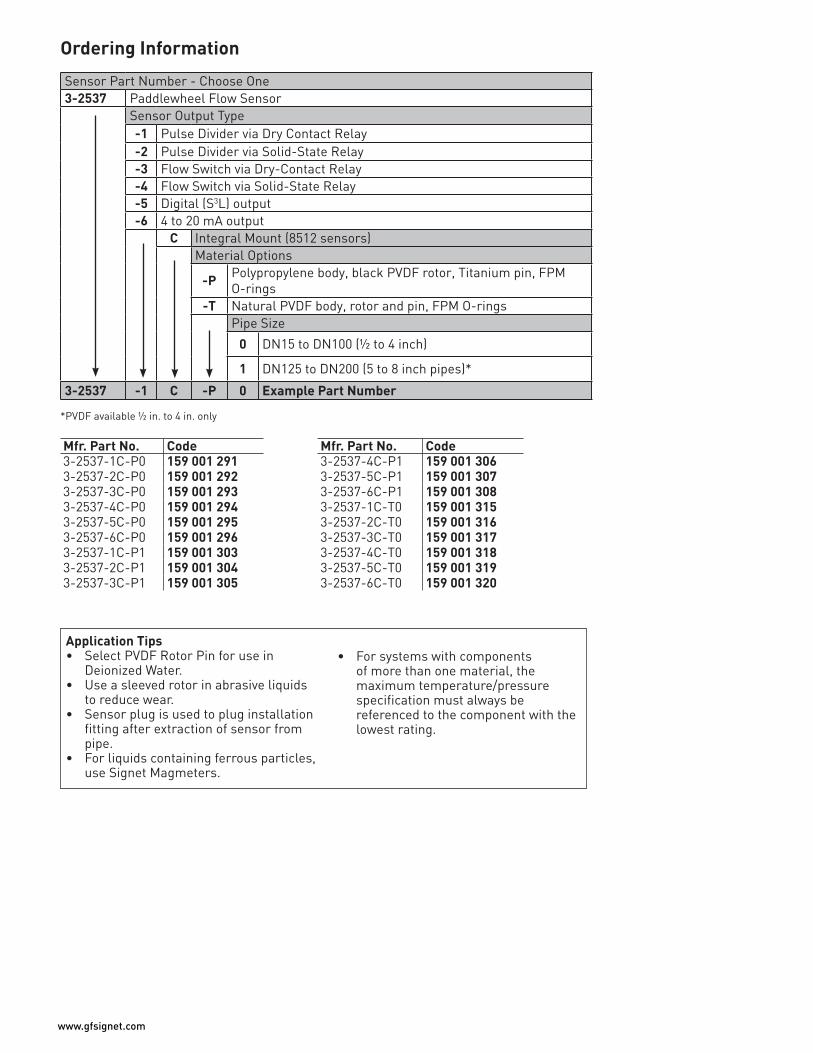
Sensor Part Number - Choose One3-2537 Paddlewheel Flow Sensor
Sensor Output Type-1 Pulse Divider via Dry Contact Relay-2 Pulse Divider via Solid-State Relay-3 Flow Switch via Dry-Contact Relay-4 Flow Switch via Solid-State Relay-5 Digital (S3L) output-6 4 to 20 mA output
C Integral Mount (8512 sensors)Material Options
-P Polypropylene body, black PVDF rotor, Titanium pin, FPM O-rings
-T Natural PVDF body, rotor and pin, FPM O-ringsPipe Size
0 DN15 to DN100 (½ to 4 inch)
1 DN125 to DN200 (5 to 8 inch pipes)*
3-2537 -1 C -P 0 Example Part Number
Application Tips• Select PVDF Rotor Pin for use in
Deionized Water.• Use a sleeved rotor in abrasive liquids
to reduce wear.• Sensor plug is used to plug installation
fitting after extraction of sensor from pipe.
• For liquids containing ferrous particles, use Signet Magmeters.
• For systems with components of more than one material, the maximum temperature/pressure specification must always be referenced to the component with the lowest rating.
*PVDF available ½ in. to 4 in. only
Mfr. Part No. Code Mfr. Part No. Code3-2537-1C-P0 159 001 291 3-2537-4C-P1 159 001 3063-2537-2C-P0 159 001 292 3-2537-5C-P1 159 001 3073-2537-3C-P0 159 001 293 3-2537-6C-P1 159 001 3083-2537-4C-P0 159 001 294 3-2537-1C-T0 159 001 3153-2537-5C-P0 159 001 295 3-2537-2C-T0 159 001 3163-2537-6C-P0 159 001 296 3-2537-3C-T0 159 001 3173-2537-1C-P1 159 001 303 3-2537-4C-T0 159 001 3183-2537-2C-P1 159 001 304 3-2537-5C-T0 159 001 3193-2537-3C-P1 159 001 305 3-2537-6C-T0 159 001 320
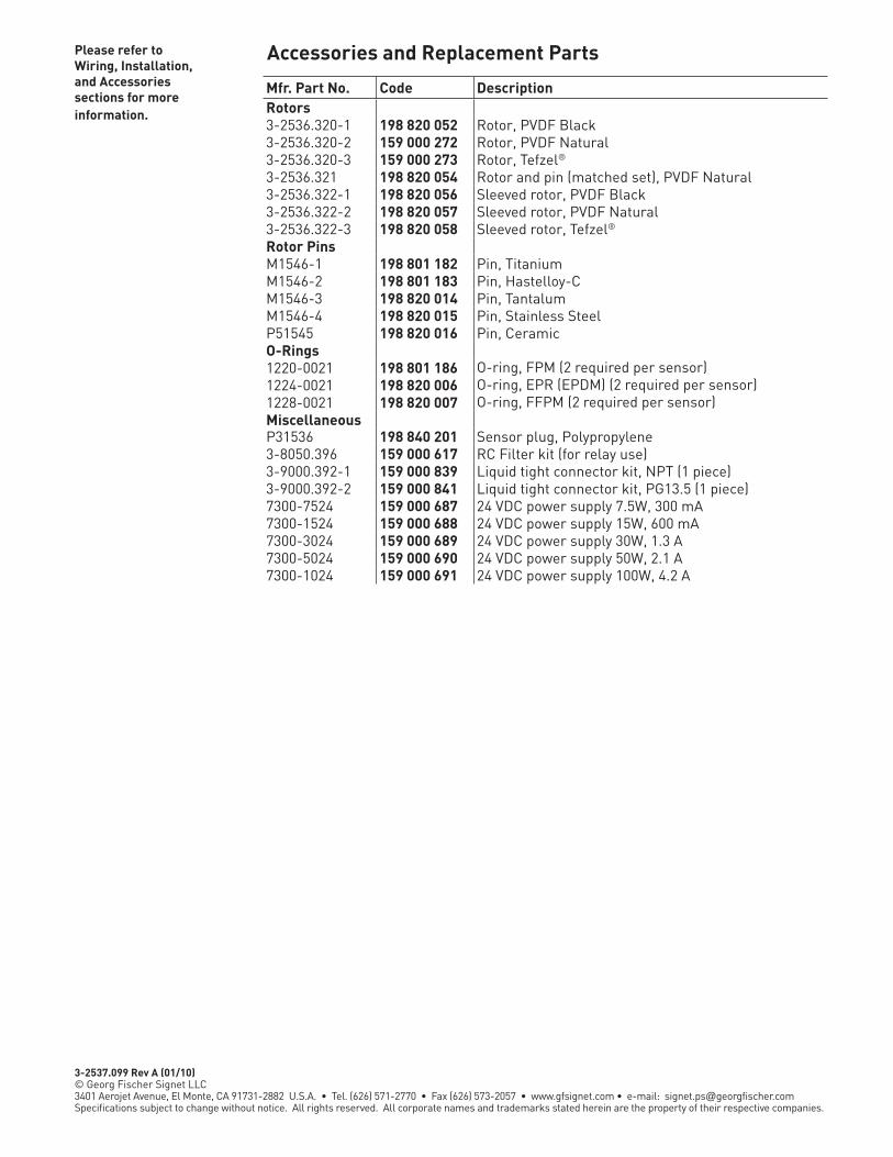
Accessories and Replacement PartsPlease refer to Wiring, Installation, and Accessories sections for more information.
Mfr. Part No. Code DescriptionRotors 3-2536.320-1 198 820 052 Rotor, PVDF Black3-2536.320-2 159 000 272 Rotor, PVDF Natural3-2536.320-3 159 000 273 Rotor, Tefzel®
3-2536.321 198 820 054 Rotor and pin (matched set), PVDF Natural3-2536.322-1 198 820 056 Sleeved rotor, PVDF Black3-2536.322-2 198 820 057 Sleeved rotor, PVDF Natural3-2536.322-3 198 820 058 Sleeved rotor, Tefzel®
Rotor PinsM1546-1 198 801 182 Pin, TitaniumM1546-2 198 801 183 Pin, Hastelloy-CM1546-3 198 820 014 Pin, TantalumM1546-4 198 820 015 Pin, Stainless SteelP51545 198 820 016 Pin, CeramicO-Rings1220-0021 198 801 186 O-ring, FPM (2 required per sensor)1224-0021 198 820 006 O-ring, EPR (EPDM) (2 required per sensor)1228-0021 198 820 007 O-ring, FFPM (2 required per sensor)MiscellaneousP31536 198 840 201 Sensor plug, Polypropylene3-8050.396 159 000 617 RC Filter kit (for relay use)3-9000.392-1 159 000 839 Liquid tight connector kit, NPT (1 piece)3-9000.392-2 159 000 841 Liquid tight connector kit, PG13.5 (1 piece)7300-7524 159 000 687 24 VDC power supply 7.5W, 300 mA7300-1524 159 000 688 24 VDC power supply 15W, 600 mA7300-3024 159 000 689 24 VDC power supply 30W, 1.3 A7300-5024 159 000 690 24 VDC power supply 50W, 2.1 A7300-1024 159 000 691 24 VDC power supply 100W, 4.2 A
3-2537.099 Rev A (01/10) © Georg Fischer Signet LLC3401 Aerojet Avenue, El Monte, CA 91731-2882 U.S.A. • Tel. (626) 571-2770 • Fax (626) 573-2057 • www.gfsignet.com • e-mail: [email protected] subject to change without notice. All rights reserved. All corporate names and trademarks stated herein are the property of their respective companies.

Signet 2540 Stainless Steel High PerformancePaddlewheel Flow Sensor
Features• Operating range 0.1 to 6 m/s (0.3 to 20 ft/s)
• Field replaceable electronics
• Non-magnetic RF detection
• Standard NPT or ISO process connections
• Hot-tap versions for installation/service without system
shutdown
• For pipe sizes up to DN900 (36 in.)
• Adjustable sensor - one size for entire
pipe range
• 7.6 m (25 ft) cable
Applications
• HVAC• Turf Irrigation• Cooling Systems• Filtration Systems• Water Distribution• Leak Detection• Pump Protection• Clarified Effluent
Totalization• Ground Water Remediation• Gravity Feed Line
The Signet 2540 Paddlewheel Flow Sensor offers the strength and corrosion resistance of stainless steel for liquid applications with low velocity measurements. Unique internal circuitry eliminates the need for magnets in the process fluid, enabling flow measurement of 0.1 to 6 m/s (0.3 to 20 ft/s) while maintaining the advantages of insertion sensor design. Rulon® B (Fluoroloy B/PTFE) bearings and Tungsten Carbide pin provide exceptional wear resistance. The Signet 2540 offers field replaceable electronics and transient
voltage suppression (TVS) to provide greater immunity to large voltage disturbances (i.e. lightning) sometimes encountered in field wiring. Sensors can be installed in DN40 to DN600 (1½ to 24 inch) pipes using the 1½ inch or ISO 7/1-R 1.5 threaded process connection. The sensors are also offered in a hot-tap configuration with a bleed valve service without process shutdown in pipes up to DN900 (36 in.). Both styles of sensors must be used in full pipes and can be used in low pressure systems.
Standard Sensor
System Overview
Signet2540 Standard orHot-tap (not shown)Flow Sensor
Signet Flow Instrument (sold separately) 5075 8550 5500 8900 5600
Signet Universal Adapter Kit (3-8050) (sold separately)
Signet Flow Instrument(sold separately)8550
Pipe, Tank, Wall MountPanel Mount
Customer SuppliedFittings
Hot-Tap Sensor
Description
LEAD FREE
RoHSCOMPLIANT
Pb

3-2540.099 Rev B (01/10) © Georg Fischer Signet LLC3401 Aerojet Avenue, El Monte, CA 91731-2882 U.S.A. • Tel. (626) 571-2770 • Fax (626) 573-2057 • www.gfsignet.com • e-mail: [email protected] subject to change without notice. All rights reserved. All corporate names and trademarks stated herein are the property of their respective companies.
Sensor Part Number 3-2540 Stainless Steel High Performance flow sensor with removable electronics
Mounting Option - Choose One-1 1½ inch NPT thread-2 1½ inch ISO thread-3 1½ inch NPT thread, Hot-Tap design*-4 1½ inch ISO thread, Hot-Tap design*
Rotor Pin Material- Tungsten Carbide
-S Stainless Steel3-2540 -1 Example Part Number
SpecificationsDimensions
457 mm (18 in.)
Bleed valve
7.6 m (25 ft)cable
O-ring seals (2)
24 mm (0.94 in.) dia.
Sensor fitting:1½ in. NPT orISO 7/1-R 1.5thread
64 mm (2½ in.) dia.
AdjustableLength
457.2 mm(18”)
Adjustablelength
190.5 mm(7.5 in.)
127 mm (5.0 in.)
Sensor fitting:1½ in. NPT orISO 7/1-R 1.5thread
O-ring seal (1)
7.6 m (25 ft)integral cable
64 mm (2½ in.) dia.
24 mm (0.94 in.) dia.
2540 Hot-Tap for 1½ to 36 in. pipes
2540 High Performance Flow Sensor for 1½ to 24 in. pipes
General Operating Range: 0.1 to 6 m/s (0.3 to 20 ft/s)Pipe size range:• Standard Version: DN40 to DN600 (1½ to 24 in.)• Hot-Tap Version: DN40 to DN900 (1½ to 36 in.)Sensor Fitting Options: • 1½ in. NPT threads• ISO 7/1-R 1.5 threadsLinearity: ±1% of full rangeRepeatability: ±0.5% of full rangeMin. Reynolds Number Required: 4500Wetted Materials • Body: 316 stainless steel (1.4401)• Fitting: 316 stainless steel (1.4401)• Fitting O-rings: FPM, optional EPR (EPDM)• Rotor: 17-4 SS Alloy• Rotor Pin: Tungsten Carbide GRP 1 (standard) stainless steel (optional)• Retainers (2): 316 stainless steel (1.4401)• Rotor Bearings (2): Rulon® B
(Fluoroloy B/PTFE)ElectricalFrequency: 15 Hz per ft/s nominalPower: 5 to 24 VDC ±10%,
regulated, 1.5 mA max.
Electrical continued Output Type: Open collector, sinking, max 10.0 mA Cable Length: 7.6 m (25 ft), can be
extended up to 300 m (1,000 ft)
Cable Type: 2-conductor twisted-pair with shield, 22AWG
Max. Temperature/Pressure Rating• Sensor with standard FPM sensor fitting O-rings: 17 bar @ 82 °C (250 psi @ 180 °F)• Sensor with optional EPR (EPDM)
sensor fitting O-rings: 17 bar @ 100 °C (250 psi @ 212 °F)
See Temperature and Pressure graphs for more information.
Operating Temperature: -18 °C to 100 °C (0 °F to 212 °F)Shipping Weight 3-2540-1/-2/-1S/-2S: 1.79 kg 3.9 lb3-2540-3/-4/-3S/-4S: 2.15 kg 4.7 lbStandards and Approvals• CE• RoHS compliant• Manufactured under ISO 9001 for Quality and ISO 14001 for Environmental
Management
Ordering Information
Accessories and Replacement Parts
Model 2540 Ordering NotesInstallation fittings and Hot-Tap valves are customer supplied.
Application Tips• For systems with
components of more than one material, the maximum temperature/pressure specification must always be referenced to the component with the lowest rating.
• Use the Conduit Adapter Kit to protect the cable-to-sensor connection when used in outdoor environments.
• Sensor electronics can be easily replaced by
3-2541.260-1 or 3-2541.260-2.
*Must use 3-1500.663 Hot-Tap installation tool (ordered separately)
Please refer to Wiring, Installation, and Accessories sections for more information.
Mfr. Part No. Code Description3-1500.663 198 820 008 Hot-Tap Installation Tool (see Installation for more info)1220-0021 198 801 186 O-ring, FPM (2 required per sensor)1224-0021 198 820 006 O-ring, EPR (EPDM) (2 required per sensor)1228-0021 198 820 007 O-ring, FFPM (2 required per sensor)3-2540.320 198 820 040 Rotor kit, 2540 Peek Bearing (old version)3-2540.321 159 000 623 Rotor kit, 2540 Tungsten Carbide Pin (new version since
January 1, 2000)3-2540.322 159 000 864 Rotor kit, stainless steel pin and rotorP52504-3 159 000 866 Rotor pin, Tungsten CarbideP52504-4 159 000 867 Rotor pin, 316 SSP52503 198 820 013 Bearing, Rulon® B (Fluoroloy B/PTFE)P52527 159 000 481 Retainers, SS (1.4401)3-2541.260-1 159 000 849 Standard replacement electronics module3-2541.260-2 159 000 850 Hot-Tap replacement electronics module5523-0222 159 000 392 Cable (per foot), 2 cond. w/shield, 22 AWGP51589 159 000 476 Conduit adapter kitP31934 159 000 466 Conduit cap
Mfr. Part No. Code Mfr. Part No. Code3-2540-1 198 840 035 3-2540-1S 159 001 5013-2540-2 198 840 036 3-2540-2S 159 001 5023-2540-3 198 840 037 3-2540-3S 159 001 5033-2540-4 198 840 038 3-2540-4S 159 001 504

Features• Test certificate
included for -X0, -X1
• Patented Magmeter technology
• No moving parts
• Bi-directional flow
• Empty pipe detection
• Installs into pipe sizes DN15 to DN900 (0.5 to 36 in.)
• Operating range 0.05 to 10 m/s (0.15 to 33 ft/s)
• Accurate measurement even in dirty liquids
• Blind 4 to 20 mA, digital/frequency, relay output
• No pressure drop • Corrosion resistant
materials; PP or PVDF with SS, Hastelloy-C, or Titanium
• Multi-language display menu available
Applications· Chemical Processing· Water and Waste Water Monitoring· Metal Recovery and
Landfill Leachate· Commercial Pools,
Spas, and Aquariums· HVAC· Irrigation· Scrubber Control· Neutralization Systems· Industrial Water Distribution
Signet 2551 Magmeter Flow Sensor
DescriptionThe Signet 2551 Magmeter is an insertion style magnetic flow sensor that features no moving parts. The patented* sensor design is available in corrosion-resistant materials to provide long-term reliability with minimal maintenance costs. Material options include PP with stainless steel, PVDF with stainless steel, PVDF with Hastelloy-C, or PVDF with Titanium. Utilizing the comprehensive line of Signet installation fittings, sensor alignment and insertion depth is automatic. These versatile, simple-to-install sensors deliver accurate flow measurement over a wide dynamic range in pipe sizes ranging from DN15 to DN900 (½ to 36 inches), satisfying the requirements of many diverse applications.
Signet 2551 Magmeters offer many output options of frequency/digital (S3L) or 4 to 20 mA which are available on both the blind and display versions. The frequency or digital (S3L) sensor output can be
used with Signet’s extensive line of flow instruments while the 4 to 20 mA output can be used for a direct input to PLCs, chart recorders, etc. Both the 4 to 20 mA output and digital (S3L) sensor interface is available for long distance signal transmission. An additional benefit is the empty pipe detection which features a zero flow output when the sensors are not completely wetted. Also, the frequency output is bi-directional while the 4 to 20 mA output can be set for uni- or bi-directional flow using the display or the 3-0250 USB to Digital (S3L) Configuration/Diagnostic setup tool which connects to PCs for programming capabilities.
In addition the display version of the 2551 Magmeter is available with relays and features permanent and resettable totalizer values which can be stored and seen on the display. Also, the display contains multi-languages with English, Spanish, German, French, Italian and Portuguese menu options.
System Overview
Signet Fittings(sold separately)
Signet Flow Instrument(sold separately)5075 85505500 89005600
Signet 8550 Flow Instrument (sold separately)
Pipe, Tank, Wall Mount Panel MountProgrammable
LogicController(or similar)
4 to 20 mA Input
OR
PLC Signet Universal Adapter Kit (3-8050) (sold separately)
Signet 2551 Magmeter
Signet 2551 Magmeter
Stand-Alone
Chart Recorder
Available in a variety of wetted materials and ideal for pipe sizes up to DN900 (36 in.)
* U.S. Patent No: 7,055,396 B1
MEASURING EQUIPMENT77CJ

www.gfsignet.com
GeneralOperating Range: 0.05 to 10 m/s (0.15 to 33 ft/s)Pipe Size Range: DN15 to DN900 (½ in. to 36 in.)Linearity: ±1% reading plus 0.01 m/s (0.033 ft/s)Repeatability: ±0.5% of reading @ 25 °C
(77 °F)Minimum Conductivity: 20 μS/cm
Wetted Materials Sensor body/Electrodes and Grounding ring:• -P0, -P1, -P2: PP/316L SS• -T0, -T1, -T2: PVDF/Titanium• -V0, -V1, -V2: PVDF/Hastelloy-C• -W0, -W1, -W2: PVDF/316L SSO-rings: • FPM (standard)• EPR (EPDM), FFPM (optional)Case: PBTDisplay Window: PolyamideProtection Rating: NEMA 4X/IP65 ElectricalPower Requirements• 4 to 20 mA: 24 VDC ±10%, regulated,
22.1 mA max.• Frequency: 5 to 24 VDC ±10%,
regulated, 15 mA max.• Digital (S3L): 5 to 6.5 VDC, 15 mA max.• Auxiliary (only required for units with relays): 9 to 24 VDC, 0.4 A maxReverse polarity and short circuit protected
Current output (4 to 20 mA): • Loop Accuracy: 32 μA max. error (25 °C @ 24 VDC)• Isolation: Low voltage < 48 VAC/DC from electrodes and auxiliary power• Maximum Cable: 300 m (1000 ft)• Error condition: 22.1 mA• Max. Loop Resistance: 300 Ω • Compatible with PLC, PC or similar equipment• 4 to 20 mA load needed Frequency Output:• Output Modes: Freq., or Mirror Relay (display version only)• Max. Pull-up Voltage: 30 VDC• Max. Current Sink: 50 mA, current limited• Maximum Cable: 300 m (1000 ft)• Compatible with Signet Model 5075, 5500, 5600, 8550, 8900
Digital (S3L) Output:• Serial ASCII, TTL level 9600 bps• Compatible with Model Signet 8900 controller
DimensionsRelay Specifications• #1, #2 Type: Mechanical SPDT Rating: 5 A @ 30 VDC max., 5 A @ 250 VDC max.• #3 Type: Solid State Rating: 50 mA @ 30 VDC, 50 mA @ 42 VACHysteresis: User adjustable for exiting alarm conditionAlarm On Trigger Delay: Adjustable (0 to 9999.9 sec.)
Relay Modes: Off, Low, High, Window, and Proportional PulseRelay Source: Flow Rate, Resettable TotalizerError Condition: Selectable; Fail Open or Closed
Display Characters: 2 x 16 Contrast: User-set in four levelsBacklighting (only on relay versions):
Requires external 9-24 VDC, 0.4 mA max.
Max. Temperature/Pressure RatingStorage Temperature: -20 °C to 70 °C (-4 °F to 158 °F)Relative Humidity: 0 to 95% (non-condensing)Operating Temperature:• Ambient: -10 °C to 70 °C (14 °F to 158 °F) • Media: 0 °C to 85 °C (32 °F to 185 °F) Maximum Operating Pressure: 10.3 bar @ 25 °C (150 psi @ 77 °F)1.4 bar @ 85 °C (20 psi @ 185 °F)
See Temperature and Pressure Graphs for more information
Standards and Approvals• CE• UL, CUL (for display versions with relays) • NEMA 4X / IP65 Enclosure (with cap installed)• U.S. Patent No. 7,055,396 B1
Specifications
116.8 mm (4.6 in.)
-X0-X1-X2
94 mm (3.7 in.)
Blind Version
79.25 mm (3.12 in.)
-X0-X1-X2
Pipe Range 1/2 to 4 in. -X0 = 58 mm (2.3 in.) 5 to 8 in. -X1 = 91 mm (3.6 in.) 10 to 12 in. -X2 = 167 mm (6.6 in.)
X = Sensor Body P, T, V, or W
95.3 mm (3.75 in.)
Display Version
Pipe Range 1/2 to 4 in. -X0 = 58 mm (2.3 in.) 5 to 8 in. -X1 = 91 mm (3.6 in.) 10 to 12 in. -X2 = 167 mm (6.6 in.)
X = Sensor Body P, T, V, or W
Index

www.gfsignet.com
Application Tips• Note minimum
process liquid conductivity requirement is
20 μs/cm• Install sensor using
standard Signet installation fittings for best results
• Sensor is capable of retrofitting into existing 515 and
2536 fittings.
Ordering Information
**This option is a programmable open collector output that is available with display versions only.
Sensor Part No.3-2551
Sensor Body (Transducer) and Electrodes/Grounding Ring Materials - Choose One-P Polypropylene and 316L SS-T PVDF and Titanium-V PVDF and Hastelloy-C-W PVDF and 316L SS
Pipe Size - Choose One0 DN15 to DN100 (½ to 4 in.)1 DN125 to DN200 (5 to 8 in.)2 DN250 to DN900 (10 to 36 in.)
Display Options - Choose One-1 No Display-2 With Display, two SPDT relays, one solid state relay
-4 With Display
Output Options - Choose One1 Frequency, Digital (S3L), programmable open collector; for use with any
Signet Flow Instrument or the 8900 Multi-Parameter Controller**2 4 to 20 mA output; for use with PLC, PC or similar equipment
3-2551 -P 0 -2 2 Example Part Number
Mfr. Part No. Code Mfr. Part No. Code3-2551-P0-11 159 001 105 3-2551-V0-11 159 001 2573-2551-P0-12 159 001 110 3-2551-V0-12 159 001 2593-2551-P0-21 159 001 267 3-2551-V0-21 159 001 2693-2551-P0-22 159 001 273 3-2551-V0-22 159 001 2753-2551-P0-41 159 001 261 3-2551-V0-41 159 001 2633-2551-P0-42 159 001 279 3-2551-V0-42 159 001 2813-2551-P1-11 159 001 106 3-2551-V1-11 159 001 2583-2551-P1-12 159 001 111 3-2551-V1-12 159 001 2603-2551-P1-21 159 001 268 3-2551-V1-21 159 001 2703-2551-P1-22 159 001 274 3-2551-V1-22 159 001 2763-2551-P1-41 159 001 262 3-2551-V1-41 159 001 2643-2551-P1-42 159 001 280 3-2551-V1-42 159 001 2823-2551-P2-11 159 001 107 3-2551-V2-11 159 001 4503-2551-P2-12 159 001 112 3-2551-V2-12 159 001 4513-2551-P2-21 159 001 435 3-2551-V2-21 159 001 4563-2551-P2-22 159 001 438 3-2551-V2-22 159 001 4573-2551-P2-41 159 001 432 3-2551-V2-41 159 001 4623-2551-P2-42 159 001 441 3-2551-V2-42 159 001 4633-2551-T0-11 159 001 108 3-2551-W0-11 150 001 2303-2551-T0-12 159 001 113 3-2551-W0-12 159 001 2313-2551-T0-21 159 001 436 3-2551-W0-21 159 001 2713-2551-T0-22 159 001 439 3-2551-W0-22 159 001 2773-2551-T0-41 159 001 433 3-2551-W0-41 159 001 2653-2551-T0-42 159 001 442 3-2551-W0-42 159 001 2833-2551-T1-11 159 001 109 3-2551-W1-11 159 001 2323-2551-T1-12 159 001 114 3-2551-W1-12 159 001 2333-2551-T1-21 159 001 437 3-2551-W1-21 159 001 2723-2551-T1-22 159 001 440 3-2551-W1-22 159 001 2783-2551-T1-41 159 001 434 3-2551-W1-41 159 001 2663-2551-T1-42 159 001 443 3-2551-W1-42 159 001 2843-2551-T2-11 159 001 448 3-2551-W2-11 159 001 4523-2551-T2-12 159 001 449 3-2551-W2-12 159 001 4533-2551-T2-21 159 001 454 3-2551-W2-21 159 001 4583-2551-T2-22 159 001 455 3-2551-W2-22 159 001 4593-2551-T2-41 159 001 460 3-2551-W2-41 159 001 4643-2551-T2-42 159 001 461 3-2551-W2-42 159 001 465

Accessories and Replacement Parts
Please refer to Wiring, Installation, and Accessories sections for more information.
Mfr. Part No. Code DescriptionO-Rings1220-0021 198 801 186 O-ring, FPM (2 required per sensor)1224-0021 198 820 006 O-ring, EPR (EPDM) (2 required per sensor)1228-0021 198 820 007 O-ring, FFPM (2 required per sensor)Replacement TransducersReplacement Transducers3-2551-P0 159 001 211 PP/316L SS, DN15 to DN100 (½ to 4 in.) pipe3-2551-P1 159 001 212 PP/316L SS, DN125 to DN200 (5 to 8 in.) pipe3-2551-P2 159 001 444 PP/316L SS, DN250 to DN900 (10 to 36 in.) pipe3-2551-T0 159 001 213 PVDF/Titanium, DN15 to DN100 (½ to 4 in.) pipe3-2551-T1 159 001 214 PVDF/Titanium, DN125 to DN200 (5 to 8 in.) pipe3-2551-T2 159 000 445 PVDF/Titanium, DN250 to DN900 (10 to 36 in.) pipe3-2551-V0 159 001 376 PVDF/Hastelloy-C, DN15 to DN100 (½ to 4 in.) pipe3-2551-V1 159 001 377 PVDF/Hastelloy-C, DN125 to DN200 (5 to 8 in.) pipe3-2551-V2 159 000 446 PVDF/Hastelloy-C, DN250 to DN900 (10 to 36 in.) pipe3-2551-W0 159 001 234 PVDF/316L SS, DN15 to DN100 (½ to 4 in.) pipe3-2551-W1 159 001 235 PVDF/316L SS, DN125 to DN200 (5 to 8 in.) pipe3-2551-W2 159 001 447 PVDF/316L SS, DN250 to DN900 (10 to 36 in.) pipeReplacement Electronics Module3-2551-11 159 001 215 Magmeter electronics, frequency or digital (S3L) output3-2551-12 159 001 216 Magmeter electronics, 4 to 20 mA output3-2551-21 159 001 372 Magmeter display electronics, frequency or
digital (S3L) output, with relays3-2551-22 159 001 373 Magmeter display electronics, 4 to 20 mA output w/relays3-2551-41 159 001 374 Magmeter display electronics, frequency or
digital (S3L) output3-2551-42 159 001 375 Magmeter display electronics, 4 to 20 mA outputOtherP31536 198 840 201 Sensor plug, Polypropylene7300-7524 159 000 687 24 VDC power supply 7.5W, 300 mA7300-1524 159 000 688 24 VDC power supply 15W, 600 mA7300-3024 159 000 689 24 VDC power supply 30W, 1.3 A7300-5024 159 000 690 24 VDC power supply 50W, 2.1 A7300-1024 159 000 691 24 VDC power supply 100W, 4.2 A3-8551.521 159 001 378 Clear plastic cap for display1222-0042 159 001 379 O-ring for clear plastic cap, EPR (EPDM)3-0250 159 001 538 USB to digital (S3L) Configuration/Diagnostic tool
3-2551.099 Rev A (01/10) © Georg Fischer Signet LLC3401 Aerojet Avenue, El Monte, CA 91731-2882 U.S.A. • Tel. (626) 571-2770 • Fax (626) 573-2057 • www.gfsignet.com • e-mail: [email protected] subject to change without notice. All rights reserved. All corporate names and trademarks stated herein are the property of their respective companies.

Signet 2552 Metal Magmeter Flow Sensors
The Signet 2552 Metal Magmeter from Georg Fischer features all-stainless steel construction. The PVDF nosepiece and FPM O-rings are the only other wetted materials. The 2552 installs quickly into standard 1¼ in. or 1½ in. pipe outlets, and is adjustable to fit pipes from DN50 to DN2550 (2 to 102 inches). Three sensor lengths allow maximum flexibility to accommodate a variety of hardware configurations, including ball valves for hot-tap installations.
When equipped with the frequency output, the 2552 is compatible with any externally powered Signet flow
instrument, while the S3L Digital output enables multi-channel compatibility with the Signet 8900 Multi-Parameter Controller. Select the blind 4 to 20 mA current output to interface directly with dataloggers, PLCs or telemetry systems.Key features include Empty Pipe Detection, LED-assisted troubleshooting, and bi-directional span capability (in 4 to 20 mA models).
The Signet 3-0250 USB to Digital (S3L) Configuration/Diagnostic Tool is available to customize every performance feature in the 2552 so it can be adapted to the user’s application requirements.
System Overview
Features• Test certificate included
for -X0, -X1
• Award winning hot-tap magnetic flow sensor up to DN2550 (102 in.)
• Patented Magmeter technology*
• Operating range 0.05 to 10 m/s (0.15 to 33 ft/s)
• Reliable operation in harsh environments
• Repeatable: ±0.5% of reading @ 25°C
• Three output options: 4 to 20 mA, Frequency,
Digital (S3L)
• ISO or NPT Threads
Applications• Municipal Water Distribution• Process and Coolant Flow• Chemical Processing• Waste Water • Mining Applications • Water Process Flow
*U.S. Patent No.: 7,055,396 BI
Signet 8550 FlowInstrument(sold separately)
Pipe, Tank, Wall Mount Panel Mount
Programmable Logic
Controller
4 to 20 mA Input
PLC Signet Universal Adapter Kit (3-8050) (sold separately)
Signet2552 Magmeter(standard or Hot-Tap)
ball or gate valve1¼” or 1½”
Weld-on weldolet1¼” or 1½” outlet
Chart Recorder
OR
Iron strap-on saddle1¼” or 1½” outlet
Signet Flow Instrument(sold separately)5075 5500560085508900
In-line Installation
nipple 1¼” or 1½”
Description

www.gfsignet.com
SpecificationsGeneralOperating Range:• Minimum: 0.05 m/s (0.15 ft/s)• Maximum: 10 m/s (33 ft/s) for pipes to
DN1200 (48 in.) 3 m/s (10 ft./s) for pipes over
DN1200 (48 in.)Pipe Size Range: DN50 to DN2550 (2 in. to 102 in.)Linearity: ±(1% reading + 0.01 m/s) ±(1% reading + 0.033 ft/s)Repeatability: ±0.5% of reading @ 25°CAccuracy: ±2% of measured value* *(in reference conditions where the fluid
is water at ambient temperature, the sensor is inserted at the correct depth and there is a fully developed flow profile which is in compliance with ISO 7145-1982 (BS 1042 section 2.2))
Minimum Conductivity: 20 μS/cm
Wetted Materials • 316L stainless steel body and electrodes• PVDF Insulator• O-rings: FPM (standard)• Cable: 4-cond + shield, PVC jacket
(Fixed cable models) or Water-resistant rubber cable assembly with Turck® NEMA 6P connector
Power Requirements• 4 to 20 mA: 24 VDC ±10%, regulated, 22.1 mA maximum• Frequency: 5 to 24 VDC ±10%, regulated, 15 mA maximum• Digital (S3L): 5 to 6.5 VDC 15 mA maximum• Reverse polarity and short circuit
protected
Cable Options• Fixed 7.6 m (25 ft) cable• Detachable water tight sensor cable with
Turck® connector sold separately, two lengths: 4 m (13 ft) or 6 m (19.5 ft)
ElectricalCurrent Output (4 to 20 mA)• Programmable and reversible• Loop Accuracy: 32 μA max. error (@ 25°C @ 24 VDC)• Temp. Drift: ±1 μA per °C max. • Power Supply Rejection: ±1 μA per V• Isolation: Low voltage < 48 VAC/DC from electrodes and auxiliary power• Maximum Cable: 300 m (1000 ft)• Max. Loop Resistance: 300 Ω• Error Condition: 22.1 mA
Electrical (continued)Frequency Output:• Compatible with Signet 5075, 5500,
5600, 8550 and 8900• Max. Pull-up Voltage: 30 VDC• Short Circuit Protected: < 30 V @ 0 Ω pull-up for one hour• Reverse Polarity Protected to -40 V for 1 hour• Overvoltage Protected to +40 V for 1 hour• Max. Current Sink: 50 mA, current limited• Maximum cable: 300 m (1000 ft)
Digital (S3L) Output:• Compatible with Signet 8900• Serial ASCII, TTL level 9600 bps• Maximum Cable: Application
dependent (See 8900 manual)
Max. Temperature/Pressure RatingStorage Temperature: -15 °C to 70 °C (5 °F to 158 °F) in non-icing conditionsOperating Temperature• Ambient: -15 °C to 70 °C (5 °F to 158 °F) in non-icing conditions• Media: -15 °C to 85 °C (5 °F to 185 °F)Maximum Operating Pressure 20.7 bar @ 25 °C (300 psi @ 77 °F)
Hot-Tap Installation Requirements• Maximum Installation Pressure:
20.7 bar (300 psi)• Maximum Installation Temp
(Insertion/Removal): 40 °C (104 °F)Do not use hot-tap installation where temperatures will exceed 40 °C or if hazardous liquids are present.
Standards and Approvals• CE• U.S. Patent No.: 7,055,396 BI• NEMA 4 (IP65) (fixed cable models)• NEMA 6P (IP68) (Submersible
cable models only) Signet recommends maximum 3 m (10 ft) submersion depth for
maximum 10 days continuous submersion.
• Manufactured under ISO 9001 for Quality and ISO 14001 for Environmental Management
Dimensions
25.4 mm1.0 in.
41 mm1.6 in.
137 mm5.4 in.
2552-2 models290 mm11.4 in.
2552-3 models432 mm17.0 in.
2552-1 models239 mm9.4 in.
2552-2 models276.3 mm10.88 in.
2552-3 models419 mm16.5 in.
2552-1 models225.5 mm
8.88 in.
32 mm (1.25 in.)Acme threads

www.gfsignet.com
Sensor Selection GuideThe 2552 Magmeter can be installed into a variety of pipe sizes. Follow the steps below to ensure that you choose the right sensor for your application.
Step 1: Determine how the sensor will be installed
• For retrofit installations, the ball valve must be at least a 1¼ in. (or 1½ in. for 2552-3) valve. The stack height, or “A” dimension (see Fig. 2), is the overall height from the top of the pipe to the top of the ball valve.
• Sensor tip must be positioned at 10% of pipe ID
B. For Hot-Tap installations:The stack height of the ball valve, nipple weldolet (threadolet) and pipe adapters should be determined before the sensor is purchased.
• For new installations, Signet recommends a 1¼ in. or 1½ in. full port ball valve, a short nipple and a weldolet (threadolet). The stack height or “A” dimension (see Fig. 2) is the overall height from the top of the pipe to the top of the ball valve before the sensor is connected.
A. For standard (non Hot-Tap) installations:The height of the weldolet (threadolet) and pipe adapter(s) should be determined before the sensor is purchased.
• For retrofit installations, the stack height, or “A” dimension (see Fig. 1), is the overall height from the top of the pipe to the highest point of the stack.
• Sensor tip must be positioned at 10% of pipe ID
• For new installations, Signet recommends a weldolet (threadolet) and an adapter to accommodate the 1¼ in. (or 1½ in. for 2552-3) sensor process threads. The stack height, or “A” dimension (see Fig. 1), is the overall height from the top of the pipe to the highest point of the stack before the sensor is connected
Step 2: Determine how the sensor will be installedOnce the “A” dimension is determined, go to the sensor selection table and find your “A” dimension on the left column. Next, find the appropriate pipe size at the top of the chart. To determine the correct sensor size locate where the pipe size column meets the max “A” dimension row.
“A” Dimension
Weldolet or Saddle
SensorHousing
Sensor
10% of pipe ID
Fig. 1Standard installation with “A” dimension using a weldolet (threadolet)
“A”Dimension
Weldolet
Nipple
BallValve
PipeWall
SensorHousing
Sensor
10% of pipe ID
Fig. 2Hot-Tap installation with “A” dimension using a ball valve, short nipple and weldolet (threadolet)
Step 3: Refer to Ordering Information to select corresponding part numbers
Legend:
1: Use 3-2552-1, max. insertion = 185 mm (7.3 in.)
2: Use 3-2552-2, max. insertion = 236 mm (9.3 in.)
3: Use 3-2552-3 max. insertion = 368 mm (14.8 in)
inch
es
2 2.5
3 to
31/
2"
4 5 6 to
8"
10 12 to
14"
16 18 20 22 24 26 to
28"
30 to
32"
34 36 to
38"
40 to
42"
48 54 60 66 72 78 84 102
DN
50 65 80 to
90
100
125
150
to 2
00
250
300
to 3
50
400
450
500
550
600
650
to 7
00
750
to 8
00
850
900
to 9
50
1000
to 1
100
1200
1400
1500
1700
1800
2000
2100
2550
mm inches
50.8 2 1 1 1 1 1 1 1 1 1 1 1 1 1 1 1 1 1 1 1 3 3 3 3 3 3 3
63.5 2.5 1 1 1 1 1 1 1 1 1 1 1 1 1 1 1 1 1 1 2 3 3 3 3 3 3 3
76.2 3 1 1 1 1 1 1 1 1 1 1 1 1 1 1 1 1 1 2 2 3 3 3 3 3 3 3
88.9 3.5 1 1 1 1 1 1 1 1 1 1 1 1 2 1 1 2 2 2 2 3 3 3 3 3 3 3
101.6 4 1 1 1 1 1 1 1 1 1 1 1 2 2 1 2 2 2 2 2 3 3 3 3 3 3 3
114.3 4.5 1 1 1 1 1 1 1 1 1 2 2 2 2 2 2 2 2 2 3 3 3 3 3 3 3
127 5 1 1 1 1 1 1 1 1 2 2 2 2 2 2 2 2 2 3 3 3 3 3 3 3 3
139.7 5.5 1 1 1 1 1 1 1 2 2 2 2 2 3 2 2 3 3 3 3 3 3 3 3 3 3
152.4 6 1 1 1 1 1 1 2 2 2 2 2 3 3 2 3 3 3 3 3 3 3 3 3 3 3
165.1 6.5 1 1 1 1 2 2 2 2 2 3 3 3 3 3 3 3 3 3 3 3 3 3 3 3
177.8 7 1 2 2 2 2 2 2 2 3 3 3 3 3 3 3 3 3 3 3 3 3 3 3
190.5 7.5 2 2 2 2 2 2 2 3 3 3 3 3 3 3 3 3 3 3 3 3 3 3
228.6 9 2 3 3 3 3 3 3 3 3 3 3 3 3 3 3 3 3 3 3 3
241.3 9.5 3 3 3 3 3 3 3 3 3 3 3 3 3 3 3 3 3 3 3
254 10 3 3 3 3 3 3 3 3 3 3 3 3 3 3 3 3 3 3
266.7 10.5 3 3 3 3 3 3 3 3 3 3 3 3 3 3 3 3 3
279.4 11 3 3 3 3 3 3 3 3 3 3 3 3 3 3 3
292.1 11.5 3 3 3 3 3 3 3 3 3 3 3 3
304.8 12 3 3 3 3 3 3 3 3 3 3
317.5 12.5 3 3 3 3 3 3 3 3
330.2 13 3 3 3 3 3 3 3
342.9 13.5 3 3 3 3 3 3
355.6 14 3 3 3 3 3
375.9 14.8 3 3
381 15
Pipe Size
Max
. "A
" D
im
This chart is based on the thickest commonly available pipe.
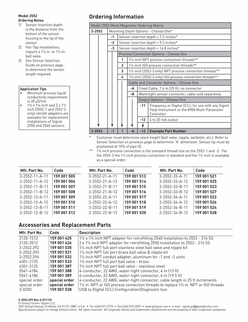
Ordering InformationModel 2552 Metal Magmeter Ordering Matrix
3-2552 Mounting Depth Options - Choose One*
-1 Sensor insertion depth = 7.3 inches*
-2 Sensor insertion depth = 9.3 inches*
-3 Sensor insertion depth = 14.8 inches*
Process Connection Options - Choose One
1 1¼ inch NPT process connection threads**
2 1¼ inch ISO process connection threads**
3 1½ inch (2552-3 only) NPT process connection threads**
4 1½ inch (2552-3 only) ISO process connection threads**
Cable and Connector Options - Choose One
-A Fixed Cable, 7.6 m (25 ft); no connector
-B Watertight sensor connector; cable sold separately
Output Options - Choose One
-11 Frequency or Digital (S3L); for use with any Signet Flow Instrument or the 8900 Multi-Parameter Controller
-12 4 to 20 mA output
3-2552 -1 1 -A -12 Example Part Number
* Customer must determine stack height (ball valve, nipple, weldolet, etc.). Refer to Sensor Selection on previous page to determine “A” dimension. Sensor tip must be positioned at 10% of pipe ID.
** 1¼ inch process connection is the standard thread size on the 2552-1 and -2: For the 2552-3 the 1½ inch process connection is standard and the 1¼ inch is available as a special order.
Model 2552Ordering Notes1) Sensor insertion depth
is the distance from the bottom of the sensor housing to the tip of the sensor.
2) Hot-Tap installations require a 1¼ in. or 1½ in. ball valve.
3) See Sensor Selection Guide on previous page to determine the sensor length required.
Accessories and Replacement Parts
Application Tips• Minimum process liquid
conductivity requirement is 20 μS/cm.
• 1½ x 1¼ inch and 2 x 1¼ inch (2552-1 and 2552-2 only) retrofit adapters are available for replacement installations of Signet 2550 and 2540 sensors.
Mfr. Part No. Code Mfr. Part No. Code Mfr. Part No. Code3-2552-11-A-11 159 001 505 3-2552-21-A-11 159 001 513 3-2552-33-A-11 159 001 5213-2552-11-A-12 159 001 506 3-2552-21-A-12 159 001 514 3-2552-33-A-12 159 001 5253-2552-11-B-11 159 001 507 3-2552-21-B-11 159 001 515 3-2552-33-B-11 159 001 5233-2552-11-B-12 159 001 508 3-2552-21-B-12 159 001 516 3-2552-33-B-12 159 001 5273-2552-12-A-11 159 001 509 3-2552-22-A-11 159 001 517 3-2552-34-A-11 159 001 5223-2552-12-A-12 159 001 510 3-2552-22-A-12 159 001 518 3-2552-34-A-12 159 001 5263-2552-12-B-11 159 001 511 3-2552-22-B-11 159 001 519 3-2552-34-B-11 159 001 5243-2552-12-B-12 159 001 512 3-2552-22-B-12 159 001 520 3-2552-34-B-12 159 001 528
Mfr. Part No. Code Description2120-1512 159 001 425 1½ x 1¼ inch NPT adapter for retrofitting 2540 installation to 2552 - 316 SS2120-2012 159 001 426 2 x 1¼ inch NPT adapter for retrofitting 2550 installation to 2552 - 316 SS3-2552.392 159 001 530 1¼ inch NPT full port stainless steel ball valve and nipple kit3-2552.393 159 001 531 1¼ inch NPT full port brass ball valve & nipple kit3-2552.394 159 001 532 1½ inch NPT conduit adapter, aluminum for -1 and -2 units4301-2125 159 001 533 1¼ inch NPT full port ball valve - brass4301-3125 159 001 387 1¼ inch NPT full port ball valve - stainless steel5541-4184 159 001 388 4-conductor, 22 AWG, water-tight connector, 4 m (13 ft)5541-4186 159 001 389 4-conductor, 22 AWG, water-tight connector, 6 m (19.5 ft)special order special order 4-conductor, 22 AWG, water-tight connector, cable length in 25 ft incrementsspecial order special order 1¼ in. NPT or ISO process connection threads to replace 1½ in. NPT or ISO threads3-0250 159 001 538 USB to Digital (S3L) Configuration/Diagnostic tool
3-2552.099 Rev A (01/10) © Georg Fischer Signet LLC3401 Aerojet Avenue, El Monte, CA 91731-2882 U.S.A. • Tel. (626) 571-2770 • Fax (626) 573-2057 • www.gfsignet.com • e-mail: [email protected] subject to change without notice. All rights reserved. All corporate names and trademarks stated herein are the property of their respective companies.

Signet 3519 Flow Wet-Tap Valve
Features• Allows sensor removal
without process shutdown
• Pressure release valve for safe sensor removal
• Dual safety lanyards
• Rugged corrosion-resistant PVC
construction and stainless steel
hardware
• Compatible with Signet 515 or 2536 Rotor-X Wet-Tap Flow Sensors
• Eliminates process downtime
Applications
• Filtration Systems• Chemical Production• Pump Protection• Scrubbers• Water Distribution• Effluent Totalization• Process Cooling Loops
DescriptionThe Signet 3519 Flow Wet-Tap Valve serves as a unique interface between the installation fitting and the wet-tap style Signet 515 or 2536 Rotor-X flow sensor. It provides a fast method of removing the sensor from the pipe under specified operating pressures. The PVC and stainless steel design of the Wet-Tap makes it resistant to corrosion and chemical attack by acids, alkalies, salt, and a number of other harsh chemicals.
The Signet 3519 Wet-Tap Valve mounts directly onto standard Signet installation fittings. The 3519 Wet-Tap consists of a flange and support plate that threads onto the pipe fitting insert, and a PVC ball valve through which an extended length sensor is inserted into the pipe.
Signet Fittings*(sold separately)
Signet Flow Instrument (sold separately)
Signet Universal Adapter Kit (3-8050) (sold separately)
Signet Flow Instrument(sold separately)
Pipe, Tank, Wall MountPanel Mount
Signet Wet-Tap Mount Flow Sensor(sold separately)515 2536
Signet 3519 Flow Wet-Tap Valve
System Overview
*See Fittings section for more information.
Assembly shown with extended length flow
sensor installed.

Specifications
Ordering Information
137 mm(5.39 in.)
121 mm/4.75 in.
185 mm/7.28 in.
General Body: PVCBall Seat: PTFESeals: FPM (std) or EPR (EPDM) also available, contact factoryHardware: 302/304SS (brackets), 18/8SS (nuts & bolts)
Max. Pressure/Temperature Rating• 7 bar max. @ 20 °C (100 psi max. @ 68 °F)• 1.4 bar max. @ 66 °C (20 psi max. @ 150 °F)Wet-Tap Maximum Installation/Removal Rating: 1.7 bar @ 22 °C (25 psi @ 72 °F)
Signet Pipe Fitting
Signet 515/2536Extended Flow Sensor
Signet 3519 Wet-TapAssembly
Dimensions
Model 515 or 2536 Wet-Tap Sensor
Shipping Weight 1.3 kg 2.86 lb
Standards & Approvals• Manufactured under ISO 9001
for Quality and ISO 14001 for Environmental Management
Model 3519 Ordering Notes1) N/C = no code
needed.2) *See model 515 data sheet
for sensor specifications.
3) **See model 2536 data sheet for sensor specifications.
4) Models 515 and 2536 Wet-Tap sensors can be ordered separately.
Application Tips• Once installed, sensor insertion and
removal can be performed without process shutdown; see installation/removal pressure specifications page.
• Use the Conduit Adapter Kit when used in outdoor environments. See Accessories section.
• For liquids containing ferrous particles, use Signet Magmeters.
See Temperature and Pressure graphs for more information.
• Use sensors with sleeved rotors in abrasive liquids to reduce wear.
• For systems with components of more than one material, maximum temperature and pressure specifications must always be referenced to the component with the lowest rating.
Part Number 3-3519 Wet-Tap Valve for 515 and 2536 Wet-Tap flow sensors
Flow RangeN/C Valve only515-P3* Valve with Model 515 sensor for ½ to 4 inch pipes515-P4* Valve with Model 515 sensor for 5 to 8 inch pipes515-P5* Valve with Model 515 sensor for 10 to 36 inch pipes2536-P3** Valve with Model 2536 sensor for ½ to 4 inch pipes2536-P4** Valve with Model 2536 sensor for 5 to 8 inch pipes2536-P5** Valve with Model 2536 sensor for 10 to 36 inch pipes
3-3519 Example Part Number - Valve Only3-3519 /515-P3 Example Part Number - Valve with Sensor
Please refer to Wiring, Installation, and Accessories sections for more information.
Components Mfr. Part No./Code3-3519 159 000 7573519/515-P3 159 000 8193519/515-P4 159 000 8203519/515-P5 159 000 821
Components Mfr. Part No./Code3519/2536-P3 159 000 8223519/2536-P4 159 000 8233519/2536-P5 159 000 824
3-3519.099 Rev B (01/10) © Georg Fischer Signet LLC3401 Aerojet Avenue, El Monte, CA 91731-2882 U.S.A. • Tel. (626) 571-2770 • Fax (626) 573-2057 • www.gfsignet.com • e-mail: [email protected] subject to change without notice. All rights reserved. All corporate names and trademarks stated herein are the property of their respective companies.

Signet 5075 Totalizing Flow Monitor
DescriptionThe Signet 5075 Totalizing Flow Monitor features a traditional analog dial for flow rate at a glance while the backlit LCD provides precision flow rate, total volume and programming information.
Significant features of this 5075 include user selectable analog dials, permanent and resettable totalizers and pulse
Features• Permanent and resettable totalizers
• Tamper proof security code
• Non-volatile memory
• Simple push-button operation
• Pulse outputs at sensor frequency and at total volume
• 1/4 DIN, NEMA 4X/IP65
• Remote totalizer reset
Applications• Waste Water Flow
Accumulation• Water Treatment
Systems• Filtration Systems• Feed Pump Pulsing• Fertigation• Irrigation• Commercial Pools
& Spas• Groundwater
Remediation• HVAC• Process Flow
Monitoring• UPW Distribution• Demineralizer
Regeneration• Process Cooling Water• Neutralization
Systems
System Overview
Analog and Digital Display
outputs at sensor frequency and at totalizer scale, The 5075 is powered by virtually any 12 to 24 VDC or VAC ±10%, regulated power source.
Connect to any of Signet’s flow sensors for a classic flow meter system.
Signet Fittingsor end connectorsas required (sold separately)
Signet 5075 Flow Instrumentincludes mounting bracketand panel gasket
Panel Mount
Signet Flow Sensor(sold separately)
See individual sensor catalog pages for required sensor mounting accessories.
5152536
525 2540 2100 2000
FLOW
2507 25522551
FLOW
Member of the ProPoint® Family of Monitors
MEASURING EQUIPMENT77CJ

3-5075.099 Rev A (01/10) © Georg Fischer Signet LLC3401 Aerojet Avenue, El Monte, CA 91731-2882 U.S.A. • Tel. (626) 571-2770 • Fax (626) 573-2057 • www.gfsignet.com • e-mail: [email protected] subject to change without notice. All rights reserved. All corporate names and trademarks stated herein are the property of their respective companies.
Accessories and Replacement Parts
Ordering Information
Dimensions
96 mm (3.8 in.)
Front View
96 mm (3.8 in.)
Mounting Clamp
Optional Splashproof Rear Cover
88 mm (3.5 in.)
Mounting Panel
Panel Gasket
91 mm (3.6 in.)
76 mm (3 in.) 96 mm (3.8 in.) 88 mm (3.5 in.)
Side View
SpecificationsGeneralOperating Range: 0.5 Hz to 10 kHzAccuracy: ± 0.5% of readingDisplay: • Analog: Six slide-in dial ranges - 0 to 2, 4, 6, 8, 10 & 100 w/multipliers• Digital: Backlit LCD, 2x16 alphanumeric
characterAdditional Functions: Sensor pulse output, volumetric pulse
output, Remote totalizer reset
Materials • Enclosure: ABS Plastic• Keypad: Silicone Rubber • Panel and case gasket: Neoprene• Window: Hard-coated polycarbonate
ElectricalPower Requirements: 12 to 24 VAC or VDC ±10%, regulated
recommended, 50 to 60 Hz, 10W max.
EnvironmentalOperating Temperature: -10 °C to 55 °C (14 °F to 131 °F)Relative Humidity: 0 to 95%, non-condensingEnclosure: NEMA 4X/IP65 front
Shipping Weight 0.8 kg 1.8 lb
Standards and Approvals• UL, CE, CUL• Manufactured under ISO 9001
for Quality and ISO 14001 for Environmental Management
Model 5075 Ordering Notes1) Panel cutout should be 92
x 92 mm (3.62 x 3.62 in.)2) Reversible dials are
included and are scaled from 0 to 2, 0 to 4, 0 to 6, 0 to 8, 0 to 10, and 0 to 100.
3) Optional splash proof rear cover can be ordered separately.
4) Flow rate unit tags are provided for labeling dials appropriately in units of gpm, lpm, etc.
Please refer to Wiring, Installation, and Accessories sections for more information.
Mfr. Part No. Code Description3-5075 198 825 007 5075 Totalizing Flow Monitor
Mfr. Part No. Code DescriptionMounting3-5000.395 198 840 227 Splashproof rear cover kit3-5000.598 198 840 225 Surface mount bracket (panel mount only)3-0000.596 159 000 641 Heavy duty wall mount bracket (panel mount only)3-5000.399 198 840 224 5 x 5 inch adapter plate to retrofit older Signet
installationsLiquid Tight Connectors3-9000.392 159 000 368 Liquid tight connector kit (includes 3 connectors)3-9000.392-1 159 000 839 Liquid tight connector kit, NPT (1 connector)3-9000.392-2 159 000 841 Liquid tight connector kit, PG 13.5 (1 connector)Replacement Parts3-5000.390 159 000 323 Installation kit (ProPoint® screws, clamps,
mounting brackets)3-5000.525-1 198 840 226 Bezel, 5000 series3-5500.390 159 000 347 Dial kit3-5500.611 159 000 348 Unit tags3-5000.397 159 000 326 5000 series window (window, keypad, & screw)Other3-5000.398 159 000 646 Protective overlay kit (10 pcs.)3-5000.075 159 000 321 110V/24 VAC transformer6400-9001 159 001 466 Intrinsic safety barrier (2 required)

Signet 5090 Sensor-Powered Flow Monitor
Features• High visibility analog
display
• Sensor-powered flow rate indication up to
60 m (200 ft) from sensor installation
• Wide flow range: 1 to 20 ft/s in pipe sizes
DN15 to D900 (½ to 36 in.)
• Single-point calibration from front panel
• Factory Mutual (FM) approved for intrinsic safety in Classes I, II and III, Division I
Applications• Filtration Systems• Hazardous Locations• Remote Flow
Monitoring• Process Cooling Water• Distribution Systems• HVAC• Process Flow
Monitoring
System Overview
DescriptionThe Signet 5090 Sensor Powered Flow Monitor is the simplest and most economical instrument in the Signet offering. It features a balanced-spring meter movement that is powered by the AC output of the Signet 515 Paddlewheel Flow Sensor. No additional power source is required.
Signet Fittings (sold separately)
Signet Flow Instrument (includes mounting bracket and panel gasket)
Panel Mount
Signet 515 Flow Sensor only (sold separately)
Sensor Powered - external power not required.
This unique system is suitable for a wide range of flow rates, and is Factory Mutual (FM) approved for intrinsic safety without the need for barriers. Packaged in a ¼ DIN housing with a NEMA 4X/IP65 front panel, the 5090 is the first choice for simple flow monitoring, even in the most demanding industrial environments.
Member of the ProPoint® Family of Monitors
MEASURING EQUIPMENT77CJ
FMAPPROVED

Mfr. Part No Code Description3-5090 198 825 000 5090 Sensor-Powered Flow Monitor
Ordering Information
Accessories and Replacement Parts
Dimensions SpecificationsGeneralOperating Range:• 0.3 to 6 m/s (1 to 20 ft/s) in pipes DN15 to DN900 (½ to 36 in.)• 7 ft/s (min. full scale range)
Reversible dial face kit includesranges 0 to 2, 4, 6, 8 and 100.
Display: Taut-band suspension meter movement,
250° deflection (not suitable for prolonged exposure to vibration)
Repeatability: ±1% of full scale
Materials• Enclosure: ABS Plastic• Panel and case gasket: Neoprene• Window: Hard-coated polycarbonate
ElectricalPower Requirements: None
EnvironmentalOperating Temperature: -10 °C to 65 °C (14 °F to 149 °F)Relative Humidity: 0 to 95%, non-condensingEnclosure: NEMA 4X/IP65 front
Shipping Weight 0.45 kg 1 lb
Standards and Approvals• FM, UL, CUL• Manufactured under ISO 9001
for Quality and ISO 14001 for Environmental Management
Model 5090 Ordering Notes1) Panel cutout should be 92 x 92 mm (3.62 x 3.62 in.)2) Reversible dials are
included and are scaled from 0 to 2, 0 to 4, 0 to 6,
0 to 8, 0 to 10, and 0 to 100.3) An optional splash proof
rear cover can be ordered separately if needed for most environments.
4) Flow rate unit tags are provided for labeling dials appropriately in units of gpm, lpm, etc.
96 mm (3.8 in.)
Front View
96 mm (3.8 in.)
Please refer to Wiring, Installation, and Accessories sections for more information.
Mfr. Part No Code DescriptionMounting3-5000.395 198 840 227 Splashproof rear cover kit3-5000.399 198 840 224 5 x 5 inch adapter plate to retrofit older Signet
installations3-5000.598 198 840 225 Surface mount bracket (panel mount only)3-0000.596 198 000 641 Heavy duty wall mount bracket (panel mount only)Liquid Tight Connectors3-9000.392 159 000 368 Liquid tight connector kit (includes 3 connectors)3-9000.392-1 159 000 839 Liquid tight connector kit, NPT (1 connector)3-9000.392-2 159 000 841 Liquid tight connector kit, PG 13.5 (1 connector)Replacement parts3-5000.390 159 000 323 Installation kit (ProPoint® screws, clamps,
and mounting brackets)3-5000.396 159 000 325 5090 window kit3-5000.525-1 198 840 226 Bezel, 5000 series3-5090.390 159 000 334 Dial kit3-5090.611 198 840 228 Unit tags3-5000.396 159 000 325 5090, 5091 window Kit
Side View
Mounting Clamp (2 ea.)
Optional Splashproof Rear Cover
88 mm(3.5 in.)
Mounting Panel
PanelGasket
91 mm(3.6 in.)
76 mm (3 in.)
88 mm (3.5 in.)96 mm (3.8 in.)
3-5090.099 Rev D (01/10) © Georg Fischer Signet LLC3401 Aerojet Avenue, El Monte, CA 91731-2882 U.S.A. • Tel. (626) 571-2770 • Fax (626) 573-2057 • www.gfsignet.com • e-mail: [email protected] subject to change without notice. All rights reserved. All corporate names and trademarks stated herein are the property of their respective companies.

DescriptionThe Signet 5500 Flow Monitor is an instrument that comes fully equipped with all of the basic tools needed for monitoring and controlling a flow system. The analog dial enables the user to easily read instantaneous flow rate, while the backlit LCD is useful for calibration, setup, and displaying totalized flow volume. The 5500 features a standard ¼ DIN package and removable wiring terminals. Power the instrument with virtually any standard 24-volt power supply (AC or DC).
Connect any one of Signet’s wide array of flow sensors, then consider which output features are best for your application.
Signet 5500 Flow MonitorFeatures• Permanent and
resettable totalizers
• Two programmable relays
• Fully scaleable active (internally powered)
4 to 20 mA output
• Tamper proof security code
• Non-volatile memory
• Intuitive software design
• Programmable pulse outputs
Applications• Waste Water Flow Accumulation• Water Treatment
Systems• Filtration Systems• Feed Pump Pulsing• Fertigation• Irrigation• Commercial Pools
& Spas• Groundwater Remediation• HVAC• Process Flow
Monitoring• UPW Distribution• Demineralizer
Regeneration• Process Cooling Water• Neutralization
Systems
System Overview
Featuring analog and digital displays and a remote resettable totalizer.
FLOW
FLOW
Two dry-contact relays can be configured for High or Low alarm operation, or they can be set to pulse operation for chemical dosing applications.
Use the internally powered 4 to 20 mA output, programmable from the front keypad, to send the flow information to any PLC or data logger.
If you use all of these output features, you still have two more output pulse terminals, one at sensor frequency, the other triggered by the totalizer. And just for added convenience, the resettable totalizer can be reset by a remote hard-wired switch, up to 30 m (100 ft), or from the front keypad.
Member of the ProPoint® Family of Monitors
MEASURING EQUIPMENT77CJ

3-5500.099 Rev E (01/10) © Georg Fischer Signet LLC3401 Aerojet Avenue, El Monte, CA 91731-2882 U.S.A. • Tel. (626) 571-2770 • Fax (626) 573-2057 • www.gfsignet.com • e-mail: [email protected] subject to change without notice. All rights reserved. All corporate names and trademarks stated herein are the property of their respective companies.
Ordering Information
Accessories and Replacement Parts
Dimensions
SIDE VIEW
Mounting Clamp (2 ea.)
Optional Splashproof Rear Cover
88 mm(3.5 in.)
Mounting Panel
PanelGasket
91 mm(3.6 in.)
76 mm (3 in.)
88 mm (3.5 in.)96 mm (3.8 in.)
Front View
96 mm (3.8 in.)
96 mm (3.8 in.)
SpecificationsGeneralOperating Range: 0.5 Hz to 10kHzAccuracy: ± 0.5% of readingDisplay: • Analog: Six slide-in dial ranges - 0 to 2, 4, 6, 8,
10 & 100 w/multipliers• Digital: Backlit LCD, 2x16 alphanumeric
character• Additional Functions: Sensor pulse output, volumetric
auxiliary pulse output, remote totalizer reset
Materials• Enclosure: ABS Plastic• Keypad: Silicone Rubber• Panel and case gasket: Neoprene• Window: Hard-coated polycarbonate
ElectricalPower Requirements: 12 to 24 VAC or DC ±10%, regulated
recommended, 50 to 60 Hz, 10W max.Current Output: • 4 to 20 mA, non-isolated, active,
internally powered
• Loop Impedance:350 Ω max. @ 12 V950 Ω max. @ 24 V
• Accuracy: ± 0.1%• Update Rate: 100 msecAlarm Contacts:• Two SPDT relays: High/Low/Pulse
programmable with adj. hysteresis for exiting alarm condition
5 A @ 30 VDC5 A @ 125 VAC3 A @ 250 VAC max.
EnvironmentalOperating Temperature: -10 °C to 55 °C (14 °F to 131 °F)Relative Humidity: 0 to 95%, non-condensingEnclosure: NEMA 4X/IP65 front
Shipping Weight 0.8 kg 1.8 lb
Standards and Approvals• UL, CE, CUL• Manufactured under ISO 9001
for Quality and ISO 14001 for Environmental Management
Model 5500 Ordering Notes1) Panel cutout should be 92 x 92 mm (3.62 x 3.62 in.)2) Reversible dials are
included and are scaled from 0 to 2, 0 to 4, 0 to 6, 0 to 8, 0 to 10, and 0 to 100.
3) An optional splash proof rear cover can be ordered separately if needed.
4) Flow rate unit tags are provided for labeling dials appropriately in units of gpm, lpm, etc.
Electrical (continued)
Please refer to Wiring, Installation, and Accessories sections for more information.
Mfr. Part No Code Description3-5500 198 825 002 5500 Flow Monitor
Mfr. Part No Code DescriptionMounting3-5000.395 198 840 227 Splashproof rear cover kit3-5000.399 198 840 224 5 x 5 inch adapter plate to retrofit older Signet
installations3-5000.598 198 840 225 Surface mount bracket (panel mount only)3-0000.596 198 000 641 Heavy duty wall mount bracket (panel mount only)Liquid Tight Connectors3-9000.392 159 000 368 Liquid tight connector kit (includes 3 connectors)3-9000.392-1 159 000 839 Liquid tight connector kit, NPT (1 connector)3-9000.392-2 159 000 841 Liquid tight connector kit, PG 13.5 (1 connector)Replacement Parts3-5000.390 159 000 323 Installation kit (ProPoint® screws, clamps,
mounting brackets)3-5000.525-1 198 840 226 Bezel, 5000 series3-5500.390 159 000 347 Dial kit 3-5500.611 198 840 230 Unit tags 3-5000.397 159 000 326 5000 series window (window, keypad, & screws)Other3-5000.398 159 000 646 Protective overlay kit (10 pcs.)3-5000.075 159 000 321 110V/24 VAC transformer3-8050.396 159 000 617 RC filter kit (for relay use)

DescriptionThe Signet 5600 Batch Controller provides control capability and process fine-tuning in a familiar package. The programming interface uses a four-button keypad and an intuitive procedure for adjusting a batching system to the best performance possible.
The standard ¼ DIN package houses an analog display panel that features a batch status indicator with count-up or count-down dials. The backlit LCD displays flow rate and volume information and batch status, as well as calibration and setup instructions. The front of the unit is NEMA 4X/IP65 and is hard-coated, high-impact and UV resistant polycarbonate.
Signet 5600 Batch ControllerFeatures• Permanent and
resettable totalizers
• Non-volatile memory
• Easy batch volume entry
• Remote start, stop & resume
• Two-stage shutdown control
• Manual or automatic overrun compensation
• Estimates time to batch completion
• Overrun alarm and missing signal alarm
• Advanced valve control
• End-of-batch trigger
• Count-up or count-down to batch completion
Applications• Batch Processes• Filter Backwash Initiation• Chemical Addition• Canning & Bottling
System Overview
FLOW
FLOW
Analog dial displays batch process; Digital LCD Displays Totalizer
The 5600 operates on 12 to 24 volts ±10%, regulated, either AC or DC . Removable terminal connections make wiring the 5600 easy. Connect any Signet flow sensor with a frequency output, then add connections to two relays for two-stage shutdown or overrun alarm functions, connect a remote start-stop switch and use the end-of-batch pulse to trigger the next step in the process. A 4 to 20 mA output is also available. Advanced features include a user-set security code, an automatic calibration option, and overrun compensation.
Member of the ProPoint® Family of Monitors
MEASURING EQUIPMENT77CJ

3-5600.099 Rev B (01/10) © Georg Fischer Signet LLC3401 Aerojet Avenue, El Monte, CA 91731-2882 U.S.A. • Tel. (626) 571-2770 • Fax (626) 573-2057 • www.gfsignet.com • e-mail: [email protected] subject to change without notice. All rights reserved. All corporate names and trademarks stated herein are the property of their respective companies.
Ordering Information
Accessories and Replacement Parts
DimensionsGeneralOperating Range: 0.5 Hz to 10 kHz, optically isolatedAccuracy: ± 0.5% of readingDisplay: • Analog: Reversible dial - 0 to 100% or 100 to 0%• Digital: Backlit LCD, 2 x 16 alphanumeric
character• Batch Size: 0 to 999,999 engineering units• Dual Totalizer: 8-digit resettable and non-resettable• Additional Functions: End of batch pulse, remote start, stop & resume. Batch in progress. Batch completion, valve
control or end of batch• Option: Two-stage shutdown, overrun
alarm, end of batch, or missing signal alarm
Materials• Enclosure: ABS Plastic• Keypad: Silicone Rubber• Panel and case gasket: Neoprene• Window: Hard-coated polycarbonate
SpecificationsElectricalPower Requirements: 12 to 24 VAC or DC ±10%,
regulated recommended, 50 to 60 Hz, 10W max.
Current Output• 4 to 20 mA, non-isolated, active,
internally powered• Loop Impedance:
350 Ω max. @ 12 V950 Ω max. @ 24 V
• Accuracy: ± 0.1%
Alarm Contacts• Two SPDT relays:
5 A @ 30 VDC5 A @ 125 VAC3 A @ 250 VAC max.
EnvironmentalOperating Temperature: -10 °C to 55 °C (14 °F to 131 °F)Relative Humidity: 0 to 95%, non-condensingEnclosure: NEMA 4X/IP65
Shipping Weight 0.8 kg 1.8 lb
Standards and Approvals• CE, UL, CUL• Manufactured under ISO 9001
for Quality and ISO 14001 for Environmental Management
Model 5600 Ordering Notes1) Panel cutout should be 92
x 92 mm (3.62 x 3.62 in.)2) A reversible dial is
included and is scaled from 0 to 100 and 100 to 0.
3) An optional splash proof rear cover can be ordered separately if needed.
96 mm (3.8 in.)
Front View
96 mm (3.8 in.)
SIDE VIEW
Mounting Clamp (2 ea.)
Optional Splashproof Rear Cover
88 mm(3.5 in.)
Mounting Panel
PanelGasket
91 mm(3.6 in.)
76 mm (3 in.)
88 mm (3.5 in.)96 mm (3.8 in.)
Please refer to Wiring, Installation, and Accessories sections for more information.
Mfr. Part No Code Description3-5600 198 825 006 Batch Controller
Mfr. Part No. Code DescriptionMounting3-5000.395 198 840 227 Splashproof rear cover kit 3-5000.399 198 840 224 5 x 5 inch adapter plate to retrofit older Signet
installations3-5000.598 198 840 225 Surface mount bracket (panel mount only)3-0000. 596 159 000 641 Heavy duty wall mount bracket (panel mount only)Liquid Tight Connectors3-9000.392 159 000 368 Liquid tight connector kit for rear cover (includes
3 connectors)3-9000.392-1 159 000 839 Liquid tight connector kit, NPT (1 connector)3-9000.392-2 159 000 841 Liquid tight connector kit, PG 13.5 (1 connector)Replacement Parts3-5000.390 159 000 323 Installation kit (ProPoint® screws, clamps, and
mounting brackets)3-5000.397 159 000 326 5000 series window kit (window, keypad, & screw)3-5000.525-1 198 840 226 Bezel, 5000 series3-5600.360 159 000 887 Replacement dial 3-5500.611 198 840 230 Unit tagsOther3-5000.398 159 000 646 Protective overlay kit (10 pcs.)3-5000.075 159 000 321 110V/24 VAC transformer3-8050.396 159 000 617 RC filter kit (for relay use)

Signet 8150 Battery Powered Flow TotalizerFeatures• Three totalizers: 2 resettable and 1 permanent, user
selectable
• Long-lasting lithium batteries
• Mounting versatility
• No-flow indicator
• Large digital display with averaging
• Simple push-button operation
• User selectable access code prevents unwanted changes
• Auto-calibration
Applications• Wastewater Flow Accumulation• Water Treatment Systems• Remote or Mobile
Treatment/Distribution Systems
• Irrigation Systems• Filtration Systems• Commercial Pools &
Spas• Groundwater Remediation• RO Concentrate• Process Flow Monitoring• UPW Distribution• Demineralizer
Regeneration• Process Cooling Water
DescriptionThe Signet 8150 Battery Operated Flow Totalizer is compatible with the Signet 515 and 525 flow sensors, and will provide years of dependable operation. The large digital display indicates flow rate and totalized flow volume simultaneously. One of the three totalizers is resettable from the front panel or a remote location, while the second resettable totalizer can only be reset by entering a user-selectable security code. The third is a permanent non-resettable totalizer.
Our intuitive software design and four-button keypad provide for simple operation while setting screen displays
and programming the system. Calibration can be easily performed by entering the Auto-Cal feature and entering a value to match an external reference. Screen displays can be modified to suit the user’s needs; along with the flow rate, any of the three totalizers can be selected as the displayed totalizer. Customers can quickly scroll through the totalizers simply by pressing any key on the keypad. A display averaging feature is included for applications where the flow in the pipe fluctuates. For applications where flow stops and starts due to production needs, a no-flow indicator will display the hours of non-flow.
System Overview
Pipe, Wall, and Tank MountPanel Mount Integral Mount
Panel Mount Pipe, Tank, Wall Mount Integral Mount Signet 8150 Flow Totalizer (includes mounting bracket and panel gasket
Signet 8150 Flow Totalizer
Signet 8150 Flow Totalizer (includes adapter and sensor)
Signet Flow Sensor(sold separately)515 525
Signet Flow Sensor(sold separately)515 525
Signet Fittings (sold separately)
Signet UniversalAdapter Kit (3-8050)(sold separately)
FLOW
Member of the ProcessPro® Family of Instruments
MEASURING EQUIPMENT77CJ
LEAD FREE
RoHSCOMPLIANT
Pb
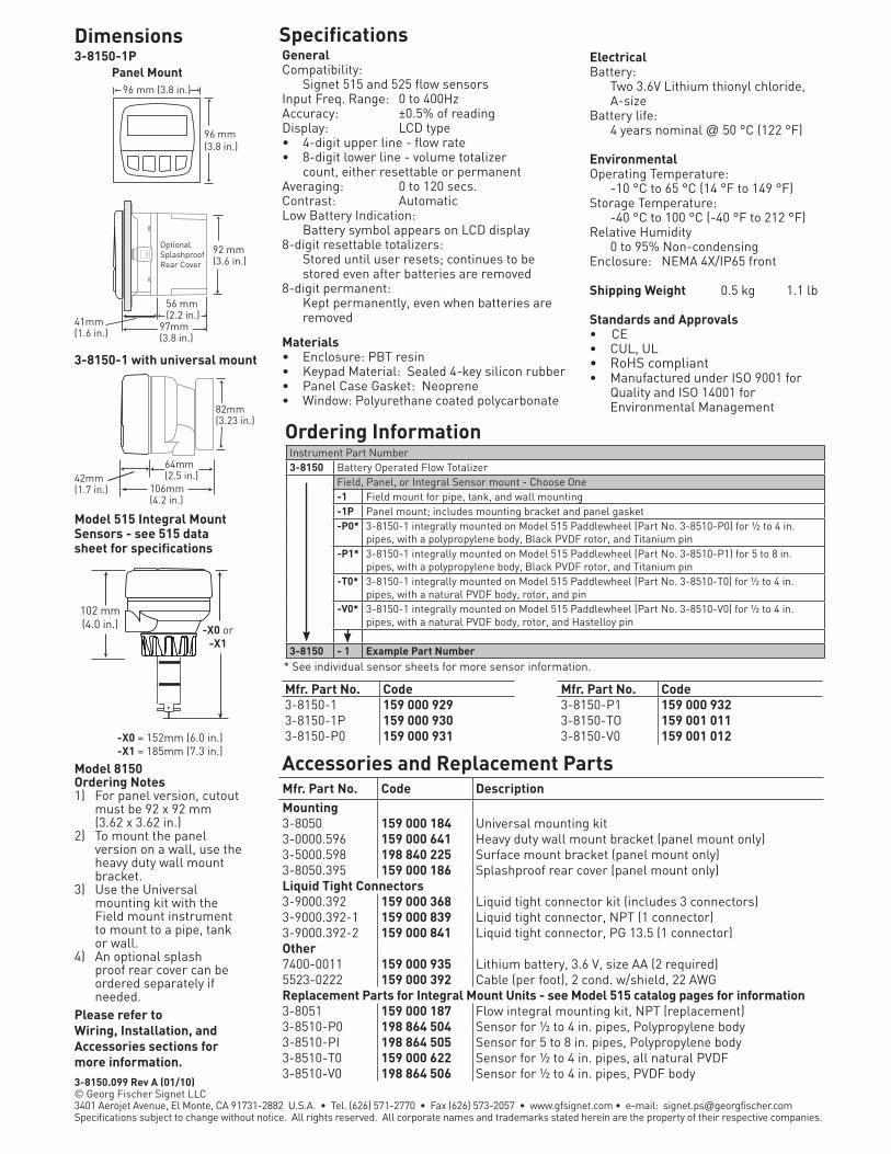
3-8150.099 Rev A (01/10) © Georg Fischer Signet LLC3401 Aerojet Avenue, El Monte, CA 91731-2882 U.S.A. • Tel. (626) 571-2770 • Fax (626) 573-2057 • www.gfsignet.com • e-mail: [email protected] subject to change without notice. All rights reserved. All corporate names and trademarks stated herein are the property of their respective companies.
Ordering Information
Accessories and Replacement Parts
Dimensions SpecificationsGeneralCompatibility: Signet 515 and 525 flow sensorsInput Freq. Range: 0 to 400HzAccuracy: ±0.5% of readingDisplay: LCD type • 4-digit upper line - flow rate• 8-digit lower line - volume totalizer count, either resettable or permanentAveraging: 0 to 120 secs. Contrast: AutomaticLow Battery Indication: Battery symbol appears on LCD display8-digit resettable totalizers: Stored until user resets; continues to be
stored even after batteries are removed8-digit permanent: Kept permanently, even when batteries are
removed
Materials• Enclosure: PBT resin• Keypad Material: Sealed 4-key silicon rubber• Panel Case Gasket: Neoprene• Window: Polyurethane coated polycarbonate
ElectricalBattery: Two 3.6V Lithium thionyl chloride,
A-sizeBattery life: 4 years nominal @ 50 °C (122 °F)
EnvironmentalOperating Temperature: -10 °C to 65 °C (14 °F to 149 °F)Storage Temperature: -40 °C to 100 °C (-40 °F to 212 °F)Relative Humidity 0 to 95% Non-condensingEnclosure: NEMA 4X/IP65 front
Shipping Weight 0.5 kg 1.1 lb
Standards and Approvals• CE• CUL, UL• RoHS compliant• Manufactured under ISO 9001 for Quality and ISO 14001 for Environmental Management
Model 8150Ordering Notes1) For panel version, cutout
must be 92 x 92 mm (3.62 x 3.62 in.)
2) To mount the panel version on a wall, use the heavy duty wall mount bracket.
3) Use the Universal mounting kit with the Field mount instrument to mount to a pipe, tank or wall.
4) An optional splash proof rear cover can be ordered separately if needed.
3-8150-1P
3-8150-1 with universal mount
Model 515 Integral Mount Sensors - see 515 data sheet for specifications
* See individual sensor sheets for more sensor information.
Panel Mount96 mm (3.8 in.)
96 mm (3.8 in.)
OptionalSplashproofRear Cover
92 mm (3.6 in.)
56 mm (2.2 in.)
97mm(3.8 in.)
41mm(1.6 in.)
102 mm (4.0 in.) -X0 or
-X1
-X0 = 152mm (6.0 in.) -X1 = 185mm (7.3 in.)
82mm(3.23 in.)
64mm(2.5 in.)42mm
(1.7 in.) 106mm (4.2 in.)
Instrument Part Number 3-8150 Battery Operated Flow Totalizer
Field, Panel, or Integral Sensor mount - Choose One-1 Field mount for pipe, tank, and wall mounting-1P Panel mount; includes mounting bracket and panel gasket-P0* 3-8150-1 integrally mounted on Model 515 Paddlewheel (Part No. 3-8510-P0) for ½ to 4 in.
pipes, with a polypropylene body, Black PVDF rotor, and Titanium pin-P1* 3-8150-1 integrally mounted on Model 515 Paddlewheel (Part No. 3-8510-P1) for 5 to 8 in.
pipes, with a polypropylene body, Black PVDF rotor, and Titanium pin-T0* 3-8150-1 integrally mounted on Model 515 Paddlewheel (Part No. 3-8510-T0) for ½ to 4 in.
pipes, with a natural PVDF body, rotor, and pin-V0* 3-8150-1 integrally mounted on Model 515 Paddlewheel (Part No. 3-8510-V0) for ½ to 4 in.
pipes, with a natural PVDF body, rotor, and Hastelloy pin
3-8150 - 1 Example Part Number
Please refer to Wiring, Installation, and Accessories sections for more information.
Mfr. Part No. Code DescriptionMounting3-8050 159 000 184 Universal mounting kit3-0000.596 159 000 641 Heavy duty wall mount bracket (panel mount only)3-5000.598 198 840 225 Surface mount bracket (panel mount only)3-8050.395 159 000 186 Splashproof rear cover (panel mount only)Liquid Tight Connectors3-9000.392 159 000 368 Liquid tight connector kit (includes 3 connectors)3-9000.392-1 159 000 839 Liquid tight connector, NPT (1 connector)3-9000.392-2 159 000 841 Liquid tight connector, PG 13.5 (1 connector)Other7400-0011 159 000 935 Lithium battery, 3.6 V, size AA (2 required)5523-0222 159 000 392 Cable (per foot), 2 cond. w/shield, 22 AWGReplacement Parts for Integral Mount Units - see Model 515 catalog pages for information3-8051 159 000 187 Flow integral mounting kit, NPT (replacement)3-8510-P0 198 864 504 Sensor for ½ to 4 in. pipes, Polypropylene body3-8510-PI 198 864 505 Sensor for 5 to 8 in. pipes, Polypropylene body3-8510-T0 159 000 622 Sensor for ½ to 4 in. pipes, all natural PVDF3-8510-V0 198 864 506 Sensor for ½ to 4 in. pipes, PVDF body
Mfr. Part No. Code Mfr. Part No. Code3-8150-1 159 000 929 3-8150-P1 159 000 9323-8150-1P 159 000 930 3-8150-TO 159 001 0113-8150-P0 159 000 931 3-8150-V0 159 001 012

Signet 8550 Flow Transmitters
Features
• 2 or 4 wire power
• Available with single or dual input/output
• 4 to 20 mA scaleable outputs
• Permanent & resettable totalizers
• Relay options available
• NEMA 4X enclosure with self-healing window
• Output simulation for complete system testing
Applications
• Flow Control and Monitoring
• Filtration or Softener Regeneration
• Effluent Totalization• Pump Protection• Feed Pump Pulsing• Ratio Control• Water Distribution• Leak Detection
DescriptionSignet 8550 Flow Transmitters are advanced instruments that convert the signal from frequency and digital (S3L) flow sensors into a 4 to 20 mA signal for long distance transmission. Configuration flexibility is maximized with single or dual input/output, two optional relays for process control, two packaging
options for integral/pipe mount or panel installation, and scalability for virtually any flow range or engineering unit. State-of-the-art electronic design ensures long-term reliability, signal stability, and simple user setup and operation.
System Overview
Pipe, Wall, Tank and Integral MountPanel Mount
Member of the ProcessPro® Family of Instruments
Signet Fittings (sold separately)
Signet Integral Mount Flow Sensor(sold separately)3-8510-XX3-8512-XX
Signet 8550 Flow Instrument (Includes mounting bracket and panel gasket)
Signet 8550 Flow Transmitter
Signet Integral Adapter Kit (3-8051) (sold separately)
Signet Universal Adapter Kit (3-8050) (sold separately)
Signet 8550 Flow Transmitter
Integral Mount Pipe, Tank, Wall Mount Panel Mount
Signet Flow Sensor(sold separately)515 2507 2540525 2536 25512000 25522100
Signet Flow Sensor(sold separately)515 2507 2540525 2536 25512000 25522100
MEASURING EQUIPMENT77CJ
LEAD FREE
RoHSCOMPLIANT
Pb

3-8550.099 Rev C (03/10) © Georg Fischer Signet LLC3401 Aerojet Avenue, El Monte, CA 91731-2882 U.S.A. • Tel. (626) 571-2770 • Fax (626) 573-2057 • www.gfsignet.com • e-mail: [email protected] subject to change without notice. All rights reserved. All corporate names and trademarks stated herein are the property of their respective companies.
Ordering Information
Accessories and Replacement Parts
Dimensions SpecificationsGeneralCompatibility:
Signet Flow Sensors with frequency outputsAccuracy: ± 0.5% of readingDisplay: Alphanumeric 2 x 16 LCDUpdate Rate: 1 secondContrast: User selectable, 5 levelsMaterials• Enclosure: PBT• Panel Case Gasket: Neoprene• Window: Polyurethane coated
polycarbonate• Keypad: Sealed 4-key silicone rubberElectricalPower: 12 to 24 VDC ±10%, regulated (-1) 90 mA max. (-2) 220 mA max. (-3) 100 mA max.Sensor Input Range: 0.5 to 1500 HzSensor Power: • 2-wire: 5 VDC ± 1% @ 1.5 mA• 3 or 4 wire: 5 VDC ± 1% @ 20 mA Optically isolated from current loop Short circuit protectedCurrent Output • 4 to 20 mA, isolated, passive, fully
adjustable and reversible• Max. Loop Impedance:
50 Ω max. @ 12 V325 Ω max. @ 18 V600 Ω max. @ 24 V
• Update Rate: 100 ms• Accuracy: ±0.03 mA
Electrical (continued)Relay Output:• Mechanical SPDT contacts: High, Low, Pulse, Off• Maximum Voltage Rating:
30 VDC @ 5 A , 250 VAC @ 5 A resistive load• Hysteresis: User selectable• Maximum 400 pulses/min.Open-Collector Output:• High, Low, Pulse, Off• Optically isolated, 50 mA max. sink, 30 VDC max. pull-up voltage.• Hysteresis: User selectable for
exiting alarm condition• Maximum 400 pulses/min.
EnvironmentalOperating Temperature:
-10 °C to 70 °C (14 °F to 158 °F) Storage Temperature:
-15 °C to 80 °C (5 °F to 176 °F)Relative Humidity:
0 to 95%, non-condensingEnclosure: NEMA 4X/IP65 (front)
Shipping Weight 0.325 kg 0.8 lb Standards and Approvals• CE, UL, CUL• RoHS compliant• Manufactured under ISO 9001 for
Quality and ISO 14001 for Environmental Management
3-8550-XP
Model 8550Ordering Notes1) Use the field mount
version to directly mount the instrument to the Model 515 or 2536 integral mount sensor. See sensor data sheet for more information.
2) Field mount and sensor can be ordered in a package. See Integral Mount for more
information.3) Panel Cutout should be
92 mm X 92 mm (3.62 in X 3.62 in.).
4) An optional splash proof rear cover for the panel mount version can be ordered separately if needed.
Field version with universal mount
96 mm (3.8 in.)
96 mm (3.8 in.)
OptionalSplashproofRear Cover
92 mm (3.6 in.)
56 mm (2.2 in.)
97mm(3.8 in.)
41mm(1.6 in.)
82mm(3.23 in.)
64mm(2.5 in.)42mm
(1.7 in.) 106mm (4.2 in.) Instrument Part Number
3-8550 ProcessPro® Flow TransmitterSensor Input, Sensor Power, Outputs - Choose One-1 One input, 2 or 4 wire, 4 to 20 mA and open collector for Hi, Lo, Pulse, or Frequency-2 One input, 4 wire, 4 to 20 mA and 2 relays for Hi, Lo, or Pulse-3 Two inputs, 2 or 4 wire, two 4 to 20 mA outputs and 2 open collectors for Hi, Lo, Pulse,
or FrequencyField or Panel Mount - Choose One- Field mountP Panel mount; includes mounting bracket and panel gasket
3-8550 - 1 Example Part Number - Field mount
Please refer to Wiring, Installation, and Accessories sections for more information.
Mfr. Part No. Code DescriptionMounting Accessories3-8050 159 000 184 Universal mounting kit3-8051 159 000 187 Flow integral mount NPT3-0000.596 159 000 641 Heavy duty wall mount bracket (panel mount only)3-5000.598 198 840 225 Surface mount bracket (panel mount only)3-8050.395 159 000 186 Splashproof rear cover (panel mount only)Liquid Tight Connectors and Other3-9000.392 159 000 368 Liquid tight connector kit for rear cover
(includes 3 connectors)3-9000.392-1 159 000 839 Liquid tight connector kit, NPT (1 connector)3-9000.392-2 159 000 841 Liquid tight connector kit, PG 13.5 (1 connector)3-8050.396 159 000 617 RC filter kit (for relay use)
Mfr. Part No. Code3-8550-1 159 000 0473-8550-1P 159 000 0483-8550-2 159 000 049
Mfr. Part No. Code3-8550-2P 159 000 0503-8550-3 159 000 0513-8550-3P 159 000 052