control over catenation in pillared paddlewheel metal...
TRANSCRIPT

Control over Catenation in Pillared Paddlewheel Metal−OrganicFramework Materials via Solvent-Assisted Linker ExchangeWojciech Bury,†,‡ David Fairen-Jimenez,§,∥ Marianne B. Lalonde,† Randall Q. Snurr,§ Omar K. Farha,*,†
and Joseph T. Hupp*,†
†Department of Chemistry and International Institute for Nanotechnology, Northwestern University, 2145 Sheridan Road, Evanston,Illinois 60208, United States‡Department of Chemistry, Warsaw University of Technology, Noakowskiego 3, 00-664 Warsaw, Poland§Department of Chemical and Biological Engineering, Northwestern University, 2145 Sheridan Road, Evanston, Illinois 60208,United States∥Department of Chemical Engineering and Biotechnology, University of Cambridge, Pembroke Street, Cambridge CB2 3RA, UnitedKingdom
*S Supporting Information
ABSTRACT: Control over catenation in a pillared paddle-wheel metal−organic framework was achieved via solvent-assisted linker exchange. The linker exchange was demon-strated on the noncatenated structure of DO-MOF, by using4,4′-bipyridine (L4) and 4,4′-azobis(pyridine) (L5) as linkers,leading to noncatenated materials SALEM-3 and SALEM-4.The de novo synthesized analogues of SALEM-3 and SALEM-4 can only be obtained as 2-fold interpenetrated frameworks.The reaction progress of the linker exchange was monitored byNMR spectroscopy, and structure and framework catenationwere characterized by powder X-ray diffraction and thermog-ravimetric methods.
KEYWORDS: catenation, metal−organic frameworks, SALE, linker exchange
■ INTRODUCTION
Metal−organic frameworks (MOFs) are crystalline, porousmaterials composed of organic linkers and metal-cluster ormetal-ion nodes.1 They have become popular targets forinvestigation due to their ultrahigh surface areas2 and their widerange of potential applications, such as gas storage andseparation,3,4 sensing,5,6 and catalysis.7 In many MOFsyntheses, especially ones where one or more of the linkers islengthy and narrow, high degrees of framework catenation (i.e.,interpenetration, or more commonly, interweaving) areobtained.8 Under particular circumstances, for some applica-tions, such as selective guest capture,9 stepwise gasadsorption,10 photoluminescence control,11 and guest-respon-sive porosity,12 network catenation has proven to be advanta-geous. However, because noncatenated systems offer largerapertures and pores than their catenated counterparts, they aretypically preferred in applications, such as chemical catalysis7
and high-pressure gas storage.4
While obtaining phase-pure, noncatenated MOFs is typicallya challenging task, several strategies, suitable for specificsystems or sets of systems, have been devised. For example,we have developed a method that allows for the separation ofcatenated and noncatenated MOFs based on density differ-ences.13 Yaghi and co-workers have synthesized catenated and
noncatenated IRMOFs separately by adjusting concentrationsof reactants.14 Zaworotko and co-workers studied the influenceof both reaction temperature and starting material concen-trations on the extent of subsequent catenation.15 Bureekaew etal.10 and Song et al.16 have shown that the degree of catenationof certain flexible frameworks can be modulated by usingsolvent molecules as templates. Similarly, the utilization ofoxalic acid as a templating agent allowed Zhou and co-workersto produce noncatenated PCN-6′ in place of catenated PCN-6.17 Another interesting approach involves modification of thelinker with a bulky pendant arm that, first, prevents catenationand, second, carries a catalytically active functional group.18 Ithas also been shown that MOFs can be constructed using netsfor which catenation is geometrically precluded (e.g., mostnonself-dual nets).19 The applicability of a sonochemicalmethod for catenation control has been demonstrated in thesynthesis of the PCN-6′/PCN-6 pair, as well as IRMOF-9 andIRMOF-10.20 Shekhah et al. have shown that they can suppresscatenation by using “liquid-phase epitaxy” on an organictemplate and then employing a step-by-step growth method.21
Received: November 20, 2012Revised: February 6, 2013Published: February 9, 2013
Article
pubs.acs.org/cm
© 2013 American Chemical Society 739 dx.doi.org/10.1021/cm303749m | Chem. Mater. 2013, 25, 739−744
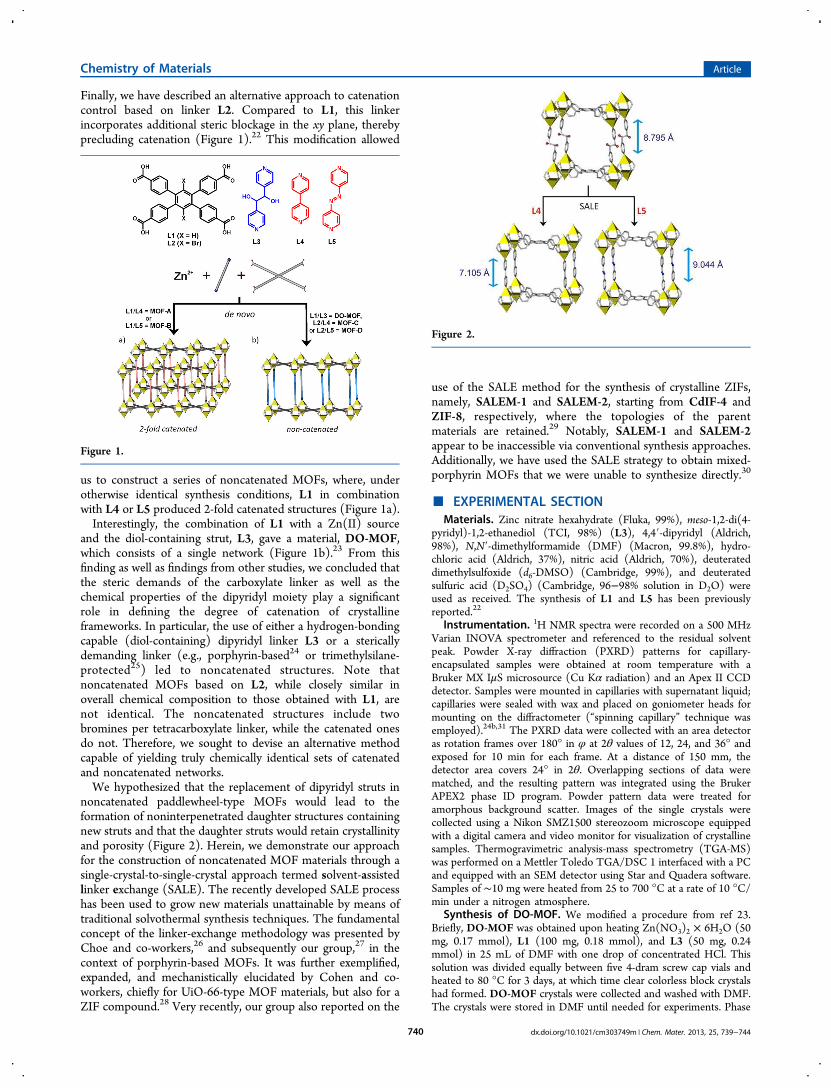
Finally, we have described an alternative approach to catenationcontrol based on linker L2. Compared to L1, this linkerincorporates additional steric blockage in the xy plane, therebyprecluding catenation (Figure 1).22 This modification allowed
us to construct a series of noncatenated MOFs, where, underotherwise identical synthesis conditions, L1 in combinationwith L4 or L5 produced 2-fold catenated structures (Figure 1a).Interestingly, the combination of L1 with a Zn(II) source
and the diol-containing strut, L3, gave a material, DO-MOF,which consists of a single network (Figure 1b).23 From thisfinding as well as findings from other studies, we concluded thatthe steric demands of the carboxylate linker as well as thechemical properties of the dipyridyl moiety play a significantrole in defining the degree of catenation of crystallineframeworks. In particular, the use of either a hydrogen-bondingcapable (diol-containing) dipyridyl linker L3 or a stericallydemanding linker (e.g., porphyrin-based24 or trimethylsilane-protected25) led to noncatenated structures. Note thatnoncatenated MOFs based on L2, while closely similar inoverall chemical composition to those obtained with L1, arenot identical. The noncatenated structures include twobromines per tetracarboxylate linker, while the catenated onesdo not. Therefore, we sought to devise an alternative methodcapable of yielding truly chemically identical sets of catenatedand noncatenated networks.We hypothesized that the replacement of dipyridyl struts in
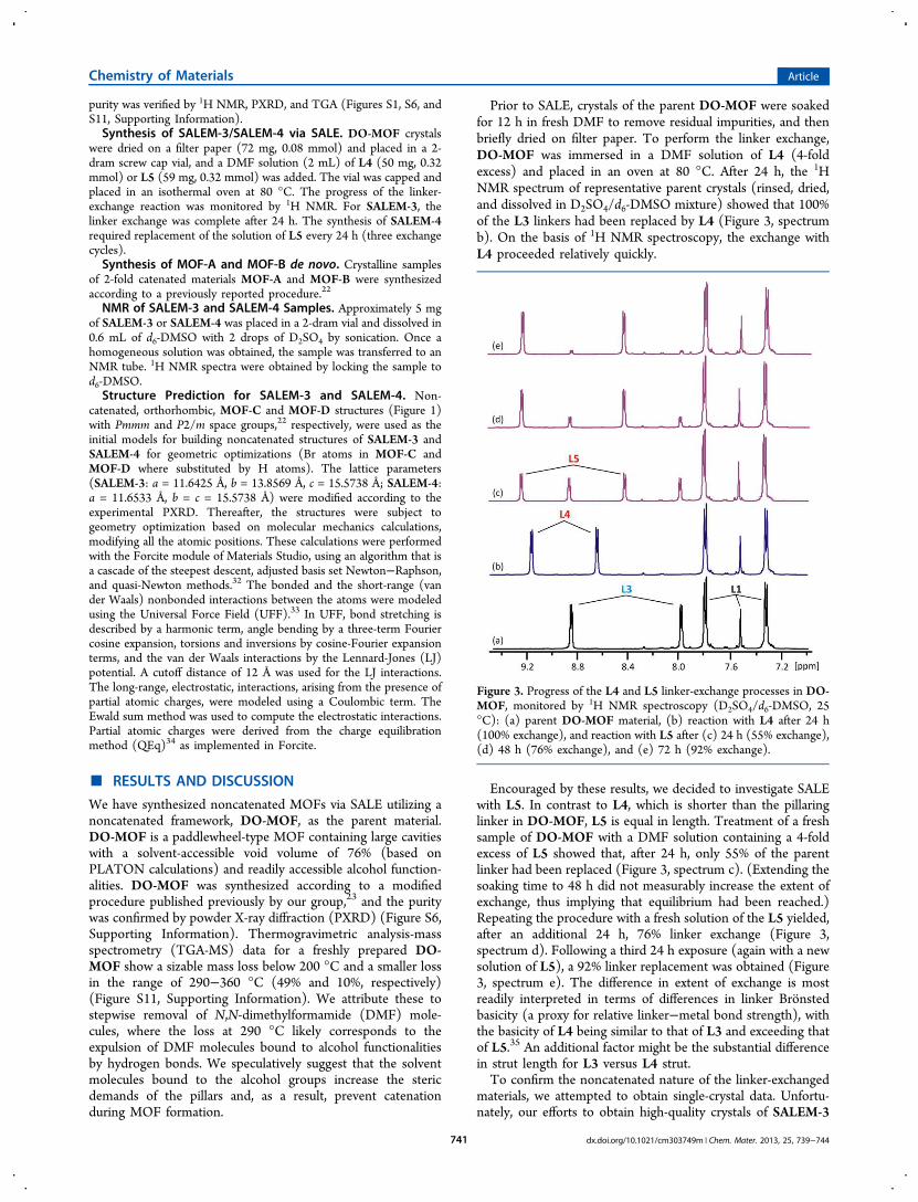
noncatenated paddlewheel-type MOFs would lead to theformation of noninterpenetrated daughter structures containingnew struts and that the daughter struts would retain crystallinityand porosity (Figure 2). Herein, we demonstrate our approachfor the construction of noncatenated MOF materials through asingle-crystal-to-single-crystal approach termed solvent-assistedlinker exchange (SALE). The recently developed SALE processhas been used to grow new materials unattainable by means oftraditional solvothermal synthesis techniques. The fundamentalconcept of the linker-exchange methodology was presented byChoe and co-workers,26 and subsequently our group,27 in thecontext of porphyrin-based MOFs. It was further exemplified,expanded, and mechanistically elucidated by Cohen and co-workers, chiefly for UiO-66-type MOF materials, but also for aZIF compound.28 Very recently, our group also reported on the
use of the SALE method for the synthesis of crystalline ZIFs,namely, SALEM-1 and SALEM-2, starting from CdIF-4 andZIF-8, respectively, where the topologies of the parentmaterials are retained.29 Notably, SALEM-1 and SALEM-2appear to be inaccessible via conventional synthesis approaches.Additionally, we have used the SALE strategy to obtain mixed-porphyrin MOFs that we were unable to synthesize directly.30
■ EXPERIMENTAL SECTIONMaterials. Zinc nitrate hexahydrate (Fluka, 99%), meso-1,2-di(4-
pyridyl)-1,2-ethanediol (TCI, 98%) (L3), 4,4′-dipyridyl (Aldrich,98%), N,N′-dimethylformamide (DMF) (Macron, 99.8%), hydro-chloric acid (Aldrich, 37%), nitric acid (Aldrich, 70%), deuterateddimethylsulfoxide (d6-DMSO) (Cambridge, 99%), and deuteratedsulfuric acid (D2SO4) (Cambridge, 96−98% solution in D2O) wereused as received. The synthesis of L1 and L5 has been previouslyreported.22
Instrumentation. 1H NMR spectra were recorded on a 500 MHzVarian INOVA spectrometer and referenced to the residual solventpeak. Powder X-ray diffraction (PXRD) patterns for capillary-encapsulated samples were obtained at room temperature with aBruker MX IμS microsource (Cu Kα radiation) and an Apex II CCDdetector. Samples were mounted in capillaries with supernatant liquid;capillaries were sealed with wax and placed on goniometer heads formounting on the diffractometer (“spinning capillary” technique wasemployed).24b,31 The PXRD data were collected with an area detectoras rotation frames over 180° in φ at 2θ values of 12, 24, and 36° andexposed for 10 min for each frame. At a distance of 150 mm, thedetector area covers 24° in 2θ. Overlapping sections of data werematched, and the resulting pattern was integrated using the BrukerAPEX2 phase ID program. Powder pattern data were treated foramorphous background scatter. Images of the single crystals werecollected using a Nikon SMZ1500 stereozoom microscope equippedwith a digital camera and video monitor for visualization of crystallinesamples. Thermogravimetric analysis-mass spectrometry (TGA-MS)was performed on a Mettler Toledo TGA/DSC 1 interfaced with a PCand equipped with an SEM detector using Star and Quadera software.Samples of ∼10 mg were heated from 25 to 700 °C at a rate of 10 °C/min under a nitrogen atmosphere.
Synthesis of DO-MOF. We modified a procedure from ref 23.Briefly, DO-MOF was obtained upon heating Zn(NO3)2 × 6H2O (50mg, 0.17 mmol), L1 (100 mg, 0.18 mmol), and L3 (50 mg, 0.24mmol) in 25 mL of DMF with one drop of concentrated HCl. Thissolution was divided equally between five 4-dram screw cap vials andheated to 80 °C for 3 days, at which time clear colorless block crystalshad formed. DO-MOF crystals were collected and washed with DMF.The crystals were stored in DMF until needed for experiments. Phase
Figure 1.
Figure 2.
Chemistry of Materials Article
dx.doi.org/10.1021/cm303749m | Chem. Mater. 2013, 25, 739−744740
purity was verified by 1H NMR, PXRD, and TGA (Figures S1, S6, andS11, Supporting Information).Synthesis of SALEM-3/SALEM-4 via SALE. DO-MOF crystals
were dried on a filter paper (72 mg, 0.08 mmol) and placed in a 2-dram screw cap vial, and a DMF solution (2 mL) of L4 (50 mg, 0.32mmol) or L5 (59 mg, 0.32 mmol) was added. The vial was capped andplaced in an isothermal oven at 80 °C. The progress of the linker-exchange reaction was monitored by 1H NMR. For SALEM-3, thelinker exchange was complete after 24 h. The synthesis of SALEM-4required replacement of the solution of L5 every 24 h (three exchangecycles).Synthesis of MOF-A and MOF-B de novo. Crystalline samples
of 2-fold catenated materials MOF-A and MOF-B were synthesizedaccording to a previously reported procedure.22
NMR of SALEM-3 and SALEM-4 Samples. Approximately 5 mgof SALEM-3 or SALEM-4 was placed in a 2-dram vial and dissolved in0.6 mL of d6-DMSO with 2 drops of D2SO4 by sonication. Once ahomogeneous solution was obtained, the sample was transferred to anNMR tube. 1H NMR spectra were obtained by locking the sample tod6-DMSO.Structure Prediction for SALEM-3 and SALEM-4. Non-
catenated, orthorhombic, MOF-C and MOF-D structures (Figure 1)with Pmmm and P2/m space groups,22 respectively, were used as theinitial models for building noncatenated structures of SALEM-3 andSALEM-4 for geometric optimizations (Br atoms in MOF-C andMOF-D where substituted by H atoms). The lattice parameters(SALEM-3: a = 11.6425 Å, b = 13.8569 Å, c = 15.5738 Å; SALEM-4:a = 11.6533 Å, b = c = 15.5738 Å) were modified according to theexperimental PXRD. Thereafter, the structures were subject togeometry optimization based on molecular mechanics calculations,modifying all the atomic positions. These calculations were performedwith the Forcite module of Materials Studio, using an algorithm that isa cascade of the steepest descent, adjusted basis set Newton−Raphson,and quasi-Newton methods.32 The bonded and the short-range (vander Waals) nonbonded interactions between the atoms were modeledusing the Universal Force Field (UFF).33 In UFF, bond stretching isdescribed by a harmonic term, angle bending by a three-term Fouriercosine expansion, torsions and inversions by cosine-Fourier expansionterms, and the van der Waals interactions by the Lennard-Jones (LJ)potential. A cutoff distance of 12 Å was used for the LJ interactions.The long-range, electrostatic, interactions, arising from the presence ofpartial atomic charges, were modeled using a Coulombic term. TheEwald sum method was used to compute the electrostatic interactions.Partial atomic charges were derived from the charge equilibrationmethod (QEq)34 as implemented in Forcite.
■ RESULTS AND DISCUSSION
We have synthesized noncatenated MOFs via SALE utilizing anoncatenated framework, DO-MOF, as the parent material.DO-MOF is a paddlewheel-type MOF containing large cavitieswith a solvent-accessible void volume of 76% (based onPLATON calculations) and readily accessible alcohol function-alities. DO-MOF was synthesized according to a modifiedprocedure published previously by our group,23 and the puritywas confirmed by powder X-ray diffraction (PXRD) (Figure S6,Supporting Information). Thermogravimetric analysis-massspectrometry (TGA-MS) data for a freshly prepared DO-MOF show a sizable mass loss below 200 °C and a smaller lossin the range of 290−360 °C (49% and 10%, respectively)(Figure S11, Supporting Information). We attribute these tostepwise removal of N,N-dimethylformamide (DMF) mole-cules, where the loss at 290 °C likely corresponds to theexpulsion of DMF molecules bound to alcohol functionalitiesby hydrogen bonds. We speculatively suggest that the solventmolecules bound to the alcohol groups increase the stericdemands of the pillars and, as a result, prevent catenationduring MOF formation.
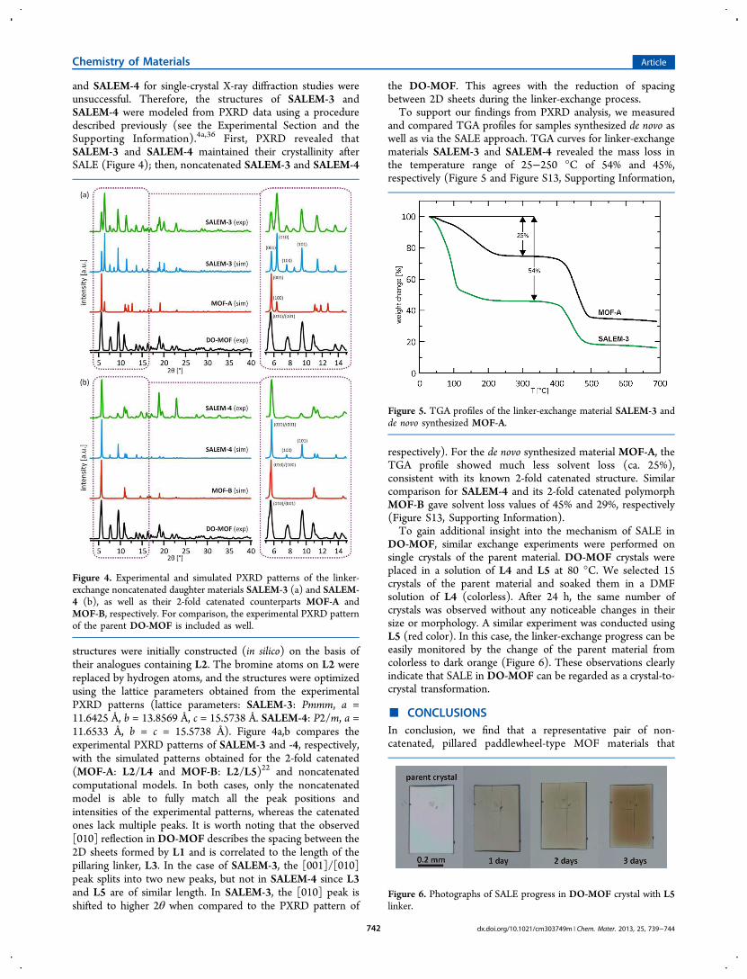
Prior to SALE, crystals of the parent DO-MOF were soakedfor 12 h in fresh DMF to remove residual impurities, and thenbriefly dried on filter paper. To perform the linker exchange,DO-MOF was immersed in a DMF solution of L4 (4-foldexcess) and placed in an oven at 80 °C. After 24 h, the 1HNMR spectrum of representative parent crystals (rinsed, dried,and dissolved in D2SO4/d6-DMSO mixture) showed that 100%of the L3 linkers had been replaced by L4 (Figure 3, spectrumb). On the basis of 1H NMR spectroscopy, the exchange withL4 proceeded relatively quickly.
Encouraged by these results, we decided to investigate SALEwith L5. In contrast to L4, which is shorter than the pillaringlinker in DO-MOF, L5 is equal in length. Treatment of a freshsample of DO-MOF with a DMF solution containing a 4-foldexcess of L5 showed that, after 24 h, only 55% of the parentlinker had been replaced (Figure 3, spectrum c). (Extending thesoaking time to 48 h did not measurably increase the extent ofexchange, thus implying that equilibrium had been reached.)Repeating the procedure with a fresh solution of the L5 yielded,after an additional 24 h, 76% linker exchange (Figure 3,spectrum d). Following a third 24 h exposure (again with a newsolution of L5), a 92% linker replacement was obtained (Figure3, spectrum e). The difference in extent of exchange is mostreadily interpreted in terms of differences in linker Bronstedbasicity (a proxy for relative linker−metal bond strength), withthe basicity of L4 being similar to that of L3 and exceeding thatof L5.35 An additional factor might be the substantial differencein strut length for L3 versus L4 strut.To confirm the noncatenated nature of the linker-exchanged
materials, we attempted to obtain single-crystal data. Unfortu-nately, our efforts to obtain high-quality crystals of SALEM-3
Figure 3. Progress of the L4 and L5 linker-exchange processes in DO-MOF, monitored by 1H NMR spectroscopy (D2SO4/d6-DMSO, 25°C): (a) parent DO-MOF material, (b) reaction with L4 after 24 h(100% exchange), and reaction with L5 after (c) 24 h (55% exchange),(d) 48 h (76% exchange), and (e) 72 h (92% exchange).
Chemistry of Materials Article
dx.doi.org/10.1021/cm303749m | Chem. Mater. 2013, 25, 739−744741
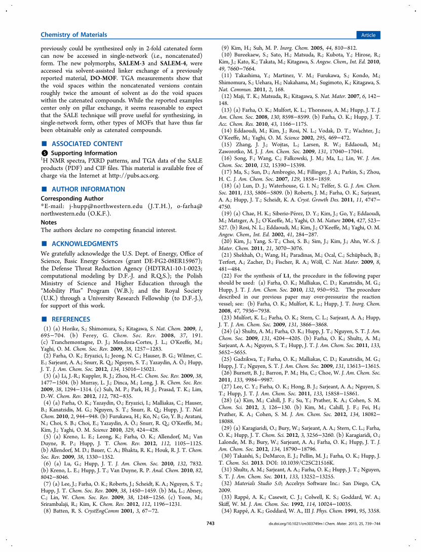
and SALEM-4 for single-crystal X-ray diffraction studies wereunsuccessful. Therefore, the structures of SALEM-3 andSALEM-4 were modeled from PXRD data using a proceduredescribed previously (see the Experimental Section and theSupporting Information).4a,36 First, PXRD revealed thatSALEM-3 and SALEM-4 maintained their crystallinity afterSALE (Figure 4); then, noncatenated SALEM-3 and SALEM-4
structures were initially constructed (in silico) on the basis oftheir analogues containing L2. The bromine atoms on L2 werereplaced by hydrogen atoms, and the structures were optimizedusing the lattice parameters obtained from the experimentalPXRD patterns (lattice parameters: SALEM-3: Pmmm, a =11.6425 Å, b = 13.8569 Å, c = 15.5738 Å. SALEM-4: P2/m, a =11.6533 Å, b = c = 15.5738 Å). Figure 4a,b compares theexperimental PXRD patterns of SALEM-3 and -4, respectively,with the simulated patterns obtained for the 2-fold catenated(MOF-A: L2/L4 and MOF-B: L2/L5)22 and noncatenatedcomputational models. In both cases, only the noncatenatedmodel is able to fully match all the peak positions andintensities of the experimental patterns, whereas the catenatedones lack multiple peaks. It is worth noting that the observed[010] reflection in DO-MOF describes the spacing between the2D sheets formed by L1 and is correlated to the length of thepillaring linker, L3. In the case of SALEM-3, the [001]/[010]peak splits into two new peaks, but not in SALEM-4 since L3and L5 are of similar length. In SALEM-3, the [010] peak isshifted to higher 2θ when compared to the PXRD pattern of
the DO-MOF. This agrees with the reduction of spacingbetween 2D sheets during the linker-exchange process.To support our findings from PXRD analysis, we measured
and compared TGA profiles for samples synthesized de novo aswell as via the SALE approach. TGA curves for linker-exchangematerials SALEM-3 and SALEM-4 revealed the mass loss inthe temperature range of 25−250 °C of 54% and 45%,respectively (Figure 5 and Figure S13, Supporting Information,
respectively). For the de novo synthesized material MOF-A, theTGA profile showed much less solvent loss (ca. 25%),consistent with its known 2-fold catenated structure. Similarcomparison for SALEM-4 and its 2-fold catenated polymorphMOF-B gave solvent loss values of 45% and 29%, respectively(Figure S13, Supporting Information).To gain additional insight into the mechanism of SALE in
DO-MOF, similar exchange experiments were performed onsingle crystals of the parent material. DO-MOF crystals wereplaced in a solution of L4 and L5 at 80 °C. We selected 15crystals of the parent material and soaked them in a DMFsolution of L4 (colorless). After 24 h, the same number ofcrystals was observed without any noticeable changes in theirsize or morphology. A similar experiment was conducted usingL5 (red color). In this case, the linker-exchange progress can beeasily monitored by the change of the parent material fromcolorless to dark orange (Figure 6). These observations clearlyindicate that SALE in DO-MOF can be regarded as a crystal-to-crystal transformation.
■ CONCLUSIONSIn conclusion, we find that a representative pair of non-catenated, pillared paddlewheel-type MOF materials that
Figure 4. Experimental and simulated PXRD patterns of the linker-exchange noncatenated daughter materials SALEM-3 (a) and SALEM-4 (b), as well as their 2-fold catenated counterparts MOF-A andMOF-B, respectively. For comparison, the experimental PXRD patternof the parent DO-MOF is included as well.
Figure 5. TGA profiles of the linker-exchange material SALEM-3 andde novo synthesized MOF-A.
Figure 6. Photographs of SALE progress in DO-MOF crystal with L5linker.
Chemistry of Materials Article
dx.doi.org/10.1021/cm303749m | Chem. Mater. 2013, 25, 739−744742
previously could be synthesized only in 2-fold catenated formcan now be accessed in single-network (i.e., noncatenated)form. The new polymorphs, SALEM-3 and SALEM-4, wereaccessed via solvent-assisted linker exchange of a previouslyreported material, DO-MOF. TGA measurements show thatthe void spaces within the noncatenated versions containroughly twice the amount of solvent as do the void spaceswithin the catenated compounds. While the reported examplescenter only on pillar exchange, it seems reasonable to expectthat the SALE technique will prove useful for synthesizing, insingle-network form, other types of MOFs that have thus farbeen obtainable only as catenated compounds.
■ ASSOCIATED CONTENT*S Supporting Information1H NMR spectra, PXRD patterns, and TGA data of the SALEproducts (PDF) and CIF files. This material is available free ofcharge via the Internet at http://pubs.acs.org.
■ AUTHOR INFORMATIONCorresponding Author*E-mail: [email protected] (J.T.H.), [email protected] (O.K.F.).NotesThe authors declare no competing financial interest.
■ ACKNOWLEDGMENTSWe gratefully acknowledge the U.S. Dept. of Energy, Office ofScience, Basic Energy Sciences (grant DE-FG2-08ER15967);the Defense Threat Reduction Agency (HDTRA1-10-1-0023;computational modeling by D.F.-J. and R.Q.S.); the PolishMinistry of Science and Higher Education through the“Mobility Plus” Program (W.B.); and the Royal Society(U.K.) through a University Research Fellowship (to D.F.-J.),for support of this work.
■ REFERENCES(1) (a) Horike, S.; Shimomura, S.; Kitagawa, S. Nat. Chem. 2009, 1,695−704. (b) Ferey, G. Chem. Soc. Rev. 2008, 37, 191.(c) Tranchemontagne, D. J.; Mendoza-Cortes, J. L.; O’Keeffe, M.;Yaghi, O. M. Chem. Soc. Rev. 2009, 38, 1257−1283.(2) Farha, O. K.; Eryazici, I.; Jeong, N. C.; Hauser, B. G.; Wilmer, C.E.; Sarjeant, A. A.; Snurr, R. Q.; Nguyen, S. T.; Yazaydin, A. O.; Hupp,J. T. J. Am. Chem. Soc. 2012, 134, 15016−15021.(3) (a) Li, J.-R.; Kuppler, R. J.; Zhou, H.-C. Chem. Soc. Rev. 2009, 38,1477−1504. (b) Murray, L. J.; Dinca, M.; Long, J. R. Chem. Soc. Rev.2009, 38, 1294−1314. (c) Suh, M. P.; Park, H. J.; Prasad, T. K.; Lim,D.-W. Chem. Rev. 2012, 112, 782−835.(4) (a) Farha, O. K.; Yazaydin, O.; Eryazici, I.; Malliakas, C.; Hauser,B.; Kanatzidis, M. G.; Nguyen, S. T.; Snurr, R. Q.; Hupp, J. T. Nat.Chem. 2010, 2, 944−948. (b) Furukawa, H.; Ko, N.; Go, Y. B.; Aratani,N.; Choi, S. B.; Choi, E.; Yazaydin, A. O.; Snurr, R. Q.; O’Keeffe, M.;Kim, J.; Yaghi, O. M. Science 2010, 329, 424−428.(5) (a) Kreno, L. E.; Leong, K.; Farha, O. K.; Allendorf, M.; VanDuyne, R. P.; Hupp, J. T. Chem. Rev. 2012, 112, 1105−1125.(b) Allendorf, M. D.; Bauer, C. A.; Bhakta, R. K.; Houk, R. J. T. Chem.Soc. Rev. 2009, 38, 1330−1352.(6) (a) Lu, G.; Hupp, J. T. J. Am. Chem. Soc. 2010, 132, 7832.(b) Kreno, L. E.; Hupp, J. T.; Van Duyne, R. P. Anal. Chem. 2010, 82,8042−8046.(7) (a) Lee, J.; Farha, O. K.; Roberts, J.; Scheidt, K. A.; Nguyen, S. T.;Hupp, J. T. Chem. Soc. Rev. 2009, 38, 1450−1459. (b) Ma, L.; Abney,C.; Lin, W. Chem. Soc. Rev. 2009, 38, 1248−1256. (c) Yoon, M.;Srirambalaji, R.; Kim, K. Chem. Rev. 2012, 112, 1196−1231.(8) Batten, R. S. CrystEngComm 2001, 3, 67−72.
(9) Kim, H.; Suh, M. P. Inorg. Chem. 2005, 44, 810−812.(10) Bureekaew, S.; Sato, H.; Matsuda, R.; Kubota, Y.; Hirose, R.;Kim, J.; Kato, K.; Takata, M.; Kitagawa, S. Angew. Chem., Int. Ed. 2010,49, 7660−7664.(11) Takashima, Y.; Martinez, V. M.; Furukawa, S.; Kondo, M.;Shimomura, S.; Uehara, H.; Nakahama, M.; Sugimoto, K.; Kitagawa, S.Nat. Commun. 2011, 2, 168.(12) Maji, T. K.; Matsuda, R.; Kitagawa, S. Nat. Mater. 2007, 6, 142−148.(13) (a) Farha, O. K.; Mulfort, K. L.; Thorsness, A. M.; Hupp, J. T. J.Am. Chem. Soc. 2008, 130, 8598−8599. (b) Farha, O. K.; Hupp, J. T.Acc. Chem. Res. 2010, 43, 1166−1175.(14) Eddaoudi, M.; Kim, J.; Rosi, N. L.; Vodak, D. T.; Wachter, J.;O’Keeffe, M.; Yaghi, O. M. Science 2002, 295, 469−472.(15) Zhang, J. J.; Wojtas, L.; Larsen, R. W.; Eddaoudi, M.;Zaworotko, M. J. J. Am. Chem. Soc. 2009, 131, 17040−17041.(16) Song, F.; Wang, C.; Falkowski, J. M.; Ma, L.; Lin, W. J. Am.Chem. Soc. 2010, 132, 15390−15398.(17) Ma, S.; Sun, D.; Ambrogio, M.; Fillinger, J. A.; Parkin, S.; Zhou,H. C. J. Am. Chem. Soc. 2007, 129, 1858−1859.(18) (a) Lun, D. J.; Waterhouse, G. I. N.; Telfer, S. G. J. Am. Chem.Soc. 2011, 133, 5806−5809. (b) Roberts, J. M.; Farha, O. K.; Sarjeant,A. A.; Hupp, J. T.; Scheidt, K. A. Cryst. Growth Des. 2011, 11, 4747−4750.(19) (a) Chae, H. K.; Siberio-Perez, D. Y.; Kim, J.; Go, Y.; Eddaoudi,M.; Matzger, A. J.; O’Keeffe, M.; Yaghi, O. M. Nature 2004, 427, 523−527. (b) Rosi, N. L.; Eddaoudi, M.; Kim, J.; O’Keeffe, M.; Yaghi, O. M.Angew. Chem., Int. Ed. 2002, 41, 284−287.(20) Kim, J.; Yang, S.-T.; Choi, S. B.; Sim, J.; Kim, J.; Ahn, W.-S. J.Mater. Chem. 2011, 21, 3070−3076.(21) Shekhah, O.; Wang, H.; Paradinas, M.; Ocal, C.; Schupbach, B.;Terfort, A.; Zacher, D.; Fischer, R. A.; Woll, C. Nat. Mater. 2009, 8,481−484.(22) For the synthesis of L1, the procedure in the following papershould be used: (a) Farha, O. K.; Malliakas, C. D.; Kanatzidis, M. G.;Hupp, J. T. J. Am. Chem. Soc. 2010, 132, 950−952. The proceduredescribed in our previous paper may over-pressurize the reactionvessel; see: (b) Farha, O. K.; Mulfort, K. L.; Hupp, J. T. Inorg. Chem.2008, 47, 7936−7938.(23) Mulfort, K. L.; Farha, O. K.; Stern, C. L.; Sarjeant, A. A.; Hupp,J. T. J. Am. Chem. Soc. 2009, 131, 3866−3868.(24) (a) Shultz, A. M.; Farha, O. K.; Hupp, J. T.; Nguyen, S. T. J. Am.Chem. Soc. 2009, 131, 4204−4205. (b) Farha, O. K.; Shultz, A. M.;Sarjeant, A. A.; Nguyen, S. T.; Hupp, J. T. J. Am. Chem. Soc. 2011, 133,5652−5655.(25) Gadzikwa, T.; Farha, O. K.; Malliakas, C. D.; Kanatzidis, M. G.;Hupp, J. T.; Nguyen, S. T. J. Am. Chem. Soc. 2009, 131, 13613−13615.(26) Burnett, B. J.; Barron, P. M.; Hu, C.; Choe, W. J. Am. Chem. Soc.2011, 133, 9984−9987.(27) Lee, C. Y.; Farha, O. K.; Hong, B. J.; Sarjeant, A. A.; Nguyen, S.T.; Hupp, J. T. J. Am. Chem. Soc. 2011, 133, 15858−15861.(28) (a) Kim, M.; Cahill, J. F.; Su, Y.; Prather, K. A.; Cohen, S. M.Chem. Sci. 2012, 3, 126−130. (b) Kim, M.; Cahill, J. F.; Fei, H.;Prather, K. A.; Cohen, S. M. J. Am. Chem. Soc. 2012, 134, 18082−18088.(29) (a) Karagiaridi, O.; Bury, W.; Sarjeant, A. A.; Stern, C. L.; Farha,O. K.; Hupp, J. T. Chem. Sci. 2012, 3, 3256−3260. (b) Karagiaridi, O.;Lalonde, M. B.; Bury, W.; Sarjeant, A. A.; Farha, O. K.; Hupp, J. T. J.Am. Chem. Soc. 2012, 134, 18790−18796.(30) Takaishi, S.; DeMarco, E. J.; Pellin, M. J.; Farha, O. K.; Hupp, J.T. Chem. Sci. 2013. DOI: 10.1039/C2SC21516K.(31) Shultz, A. M.; Sarjeant, A. A.; Farha, O. K.; Hupp, J. T.; Nguyen,S. T. J. Am. Chem. Soc. 2011, 133, 13252−13255.(32) Materials Studio 5.0; Accelrys Software Inc.: San Diego, CA,2009.(33) Rappe, A. K.; Casewit, C. J.; Colwell, K. S.; Goddard, W. A.;Skiff, W. M. J. Am. Chem. Soc. 1992, 114, 10024−10035.(34) Rappe, A. K.; Goddard, W. A., III J. Phys. Chem. 1991, 95, 3358.
Chemistry of Materials Article
dx.doi.org/10.1021/cm303749m | Chem. Mater. 2013, 25, 739−744743

(35) (a) The pKa values for monoprotonated linkers L3, L4, and L5are estimated to be 5.29, 5.25 and 4.23, respectively. The estimateswere obtained by using: pKa Calculator Plugin , Marvin 5.8.0;ChemAxon, 2012. http://www.chemaxon.com. For the details of themethod of estimation of pKa values (an approach based on calculatedatomic charges), see: (b) Dixon, S. L.; Jurs, P. C. J. Comput. Chem.1993, 14, 1460−1467.(36) (a) Strutt, N. L.; Fairen-Jimenez, D.; Iehl, J.; Lalonde, M. B.;Snurr, R. Q.; Farha, O. K.; Hupp, J. T.; Stoddart, J. F. J. Am. Chem. Soc.2012, 134, 17436−17439. (b) Fairen-Jimenez, D.; Colon, Y. J.; Farha,O. K.; Bae, Y.-S.; Hupp, J. T.; Snurr, R. Q. Chem. Commun. 2012, 48,10496−10498.
Chemistry of Materials Article
dx.doi.org/10.1021/cm303749m | Chem. Mater. 2013, 25, 739−744744