signalling design principle – etcs level 1 · 2019-05-21 · t hr sc 10031 st signalling design...
TRANSCRIPT

Signalling Design Principle – ETCS Level 1
T HR SC 10031 ST
Standard
Version 3.0
Issue date: 18 April 2019
© State of NSW through Transport for NSW 2019

T HR SC 10031 ST Signalling Design Principle – ETCS Level 1
Version 3.0 Issue date: 18 April 2019
Important message This document is one of a set of standards developed solely and specifically for use on
Transport Assets (as defined in the Asset Standards Authority Charter). It is not suitable for any
other purpose.
The copyright and any other intellectual property in this document will at all times remain the
property of the State of New South Wales (Transport for NSW).
You must not use or adapt this document or rely upon it in any way unless you are providing
products or services to a NSW Government agency and that agency has expressly authorised
you in writing to do so. If this document forms part of a contract with, or is a condition of
approval by a NSW Government agency, use of the document is subject to the terms of the
contract or approval. To be clear, the content of this document is not licensed under any
Creative Commons Licence.
This document may contain third party material. The inclusion of third party material is for
illustrative purposes only and does not represent an endorsement by NSW Government of any
third party product or service.
If you use this document or rely upon it without authorisation under these terms, the State of
New South Wales (including Transport for NSW) and its personnel does not accept any liability
to you or any other person for any loss, damage, costs and expenses that you or anyone else
may suffer or incur from your use and reliance on the content contained in this document. Users
should exercise their own skill and care in the use of the document.
This document may not be current and is uncontrolled when printed or downloaded. Standards
may be accessed from the Transport for NSW website at www.transport.nsw.gov.au
For queries regarding this document, please email the ASA at [email protected] or visit www.transport.nsw.gov.au © State of NSW through Transport for NSW 2019

T HR SC 10031 ST Signalling Design Principle – ETCS Level 1
Version 3.0 Issue date: 18 April 2019
Standard governance
Owner: Lead Signals and Control Systems Engineer, Asset Standards Authority
Authoriser: Chief Engineer, Asset Standards Authority
Approver: Executive Director, Asset Standards Authority on behalf of the ASA Configuration Control Board
Document history
Version Summary of changes
1.0 First issued 07 July 2017
2.0 Second issued 28 March 2018. The changes from the previous version include clarification to the following key elements: • balise naming • balise placement • confidence interval calculation • balise message consistency and linking • provision of repositioning • gradient simplification • requirements for providing redundancy and safety in design • requirements for LSSMA • application for virtual balise covers (VBCs) • application of level transition borders • speed information to be sent from the trackside • yard entry and exit • wrong running requirements • provision of ETCS trainstops
3.0 Third issue. The changes from the previous version include the following: • updated confidence interval calculation • updated buffer stop configuration • updated repositioning expectation window and the minimum distance formula for balise
placement • updated ERA Braking tool parameters • clarification on the level transition announcement distance calculation • updated requirement on combining big metal mass with other functions • updated wrong running exit exception conditions • addition of the toroidal transformer requirement • updated high risk turnout assessment criteria • error corrections and formatting updates • updated level transition border placement conditions
© State of NSW through Transport for NSW 2019 Page 3 of 90

T HR SC 10031 ST Signalling Design Principle – ETCS Level 1
Version 3.0 Issue date: 18 April 2019
Preface
The Asset Standards Authority (ASA) is a key strategic branch of Transport for NSW (TfNSW).
As the network design and standards authority for NSW Transport Assets, as specified in the
ASA Charter, the ASA identifies, selects, develops, publishes, maintains and controls a suite of
requirements documents on behalf of TfNSW, the asset owner.
The ASA deploys TfNSW requirements for asset and safety assurance by creating and
managing TfNSW's governance models, documents and processes. To achieve this, the ASA
focuses on four primary tasks:
• publishing and managing TfNSW's process and requirements documents including TfNSW
plans, standards, manuals and guides
• deploying TfNSW's Authorised Engineering Organisation (AEO) framework
• continuously improving TfNSW’s Asset Management Framework
• collaborating with the Transport cluster and industry through open engagement
The AEO framework authorises engineering organisations to supply and provide asset related
products and services to TfNSW. It works to assure the safety, quality and fitness for purpose of
those products and services over the asset's whole-of-life. AEOs are expected to demonstrate
how they have applied the requirements of ASA documents, including TfNSW plans, standards
and guides, when delivering assets and related services for TfNSW.
Compliance with ASA requirements by itself is not sufficient to ensure satisfactory outcomes for
NSW Transport Assets. The ASA expects that professional judgement be used by competent
personnel when using ASA requirements to produce those outcomes.
About this document
This standard forms a part of the TfNSW suite of railway signalling principles which detail the
design requirements of the complete signalling system. To gain a complete overview of
signalling design requirements, this standard should be read in conjunction with the suite of
signalling design principle standards.
This standard specifically covers the implementation of the European train control system
(ETCS) level 1.
This standard has been developed by the ASA in consultation with other TfNSW agencies and
industry representatives.
This document has been revised to align with the automatic train protection (ATP) project
(formerly known as the advanced train control mitigation system (AMS) project and provide
clarification to design requirements throughout the document.
© State of NSW through Transport for NSW 2019 Page 4 of 90

T HR SC 10031 ST Signalling Design Principle – ETCS Level 1
Version 3.0 Issue date: 18 April 2019
Table of contents 1. Introduction .............................................................................................................................................. 7
2. Purpose .................................................................................................................................................... 7 2.1. Scope ..................................................................................................................................................... 7 2.2. Application ............................................................................................................................................. 7
3. Reference documents ............................................................................................................................. 8
4. Terms and definitions ............................................................................................................................. 9
5. Balises and balise groups .................................................................................................................... 10 5.1. Balise identification .............................................................................................................................. 11 5.2. Balise placement ................................................................................................................................. 14
6. Data functions ........................................................................................................................................ 16 6.1. Confidence interval .............................................................................................................................. 17 6.2. Linking .................................................................................................................................................. 17 6.3. ETCS onboard equipment modes ....................................................................................................... 23 6.4. Movement authorities .......................................................................................................................... 25 6.5. Gradient ............................................................................................................................................... 26 6.6. Target speed monitoring ...................................................................................................................... 27 6.7. National values .................................................................................................................................... 29 6.8. Data variables ...................................................................................................................................... 31 6.9. Virtual balise cover .............................................................................................................................. 32
7. Fixed balise group functions ................................................................................................................ 33 7.1. Level transitions ................................................................................................................................... 33 7.2. Speed signs ......................................................................................................................................... 37 7.3. Calibration ............................................................................................................................................ 46 7.4. Buffer stops .......................................................................................................................................... 47 7.5. Yards .................................................................................................................................................... 51 7.6. Turning back ........................................................................................................................................ 56 7.7. Big metal masses ................................................................................................................................ 56 7.8. Wrong running ..................................................................................................................................... 59
8. Controlled balise group functions ....................................................................................................... 67 8.1. Lineside electronic units ...................................................................................................................... 67 8.2. ETCS trainstops ................................................................................................................................... 70 8.3. High-risk turnouts ................................................................................................................................. 73 8.4. High-risk overruns ................................................................................................................................ 79 8.5. Approach balise groups ....................................................................................................................... 83 8.6. Look-ahead .......................................................................................................................................... 86
9. Combining functions ............................................................................................................................. 88
10. Cascading functions ............................................................................................................................. 88 10.1. Low-risk turnouts in rear of high-risk speed signs ........................................................................... 88 10.2. Speed signs and speed updates inside TSM areas ........................................................................ 88
© State of NSW through Transport for NSW 2019 Page 5 of 90

T HR SC 10031 ST Signalling Design Principle – ETCS Level 1
Version 3.0 Issue date: 18 April 2019
10.3. LSSMA value considerations ........................................................................................................... 90 10.4. LSSMA display considerations ........................................................................................................ 90
© State of NSW through Transport for NSW 2019 Page 6 of 90
T HR SC 10031 ST Signalling Design Principle – ETCS Level 1
Version 3.0 Issue date: 18 April 2019
1. Introduction The European train control system (ETCS) is a standardised automatic train protection (ATP)
system that provides various options to permit flexible application across different railway
jurisdictions.
ETCS onboard equipment receives information related to the track ahead from ETCS trackside
equipment, and together with train parameters uses this information to determine speed and
distance supervision parameters. If a supervision limit is exceeded, then the onboard equipment
triggers one or more of the following:
• audible and visual warnings to the driver
• traction cut-off
• service brake application
• emergency brake application
2. Purpose This standard specifies the requirements and design principles for ETCS level 1 trackside
implementation to mitigate derailment and collision risks.
2.1. Scope This document specifies the design requirements for ETCS level 1 trackside implementation in
the electrified areas of the rail passenger network.
The trackside implementation complements the fitment of onboard ETCS equipment on electric
multiple units (EMUs) only; however, the onboard system is out of scope of this document.
Any requirements in this document that are an amendment from the European Union Agency
for Railways (ERA) ETCS specifications are explicitly stated as such.
2.2. Application This standard applies to Authorised Engineering Organisations (AEOs) engaged to carry out the
preliminary and detailed signal design for new and existing installations in the rail passenger
network within the area bounded by Newcastle (in the north), Richmond (in the northwest),
Bowenfels (in the west), Macarthur (in the southwest) and Bomaderry (in the south), and all
connection lines and sidings within these areas, but excluding private sidings, freight lines and
non-electrified lines.
© State of NSW through Transport for NSW 2019 Page 7 of 90

T HR SC 10031 ST Signalling Design Principle – ETCS Level 1
Version 3.0 Issue date: 18 April 2019
3. Reference documents The following documents are cited in the text. For dated references, only the cited edition
applies. For undated references, the latest edition of the referenced document applies.
International standards
ERTMS/ETCS Subset-026-3 System Requirements Specification – Chapter 3 – Principles
ETRMS/ETCS Subset-026-4 System Requirements Specification – Chapter 4 – Modes and
Transitions
ERTMS/ETCS Subset-026-7 System Requirements Specification – Chapter 7 – ERTMS/ETCS
language
ERTMS/ETCS Subset-026-8 System Requirements Specification – Chapter 8 – Messages
ERTMS/ETCS Subset-036 FFFIS for Eurobalise
ERTMS/ETCS Subset-040 Dimensioning and Engineering rules
Note - these standards were released in conjunction with ETCS Baseline 3 MR 1,
Issue 3.4.0
Transport for NSW standards
EGG 1656 Balise Placement and Metal Mass Assessment Guide
SPG 0706 Installation of Trackside Equipment
SPG 0708 Small Buildings and Location Cases
T HR SC 00003 ST Circuit Design Standard – ETCS Level 1 Interface Circuits
T HR SC 01650 SP ETCS Onboard Equipment
T MU AM 01007 TI Asset Reference Codes Register
TS TOC 3 Train Operating Conditions (TOC) Manual – Track Diagrams
Other reference documents
Advanced train control Migration System (AMS) Specifications – Gradient Simplification Design
Guideline
AMS Project Specifications – AMS Design Guideline for Repositioning Expectation Window
RailSafe NSY 514 Special Proceed Authority
Sydney Trains, 2019, PR S 45012 Identification of High Risk Turnouts
This document is not publicly available. To obtain access email
© State of NSW through Transport for NSW 2019 Page 8 of 90

T HR SC 10031 ST Signalling Design Principle – ETCS Level 1
Version 3.0 Issue date: 18 April 2019
4. Terms and definitions The following terms and definitions apply in this document:
ATP automatic train protection
CBI computer-based interlocking
DMI driver machine interface
DPU data pick-up unit (track circuit pin-point detector)
EMU electric multiple unit
EOA end of authority
ERA European Union Agency for Railways (formerly European Railway Agency)
ETCS European train control system
FS full supervision (mode)
ETCS level 0 a level of ERTMS/ETCS
ETCS level 1 a level of ERTMS/ETCS
LEU lineside electronic unit
LS limited supervision (mode)
LSSMA lowest supervised speed within the movement authority
MA movement authority
outer signal a signal one or more blocks in the rear of:
• the home signal of a turnout, or
• the protecting signal of a high-risk overrun
N_PIG balise position in group number
protecting signal a stop signal immediately in the rear of a hazard point for a high-risk overrun
SR staff responsible (mode)
SSP static speed profile
SvL supervised location
TSM target speed monitoring
TSW temporary speed warning
TSR temporary speed restriction (ETCS function)
VAD vertical alignment database
© State of NSW through Transport for NSW 2019 Page 9 of 90

T HR SC 10031 ST Signalling Design Principle – ETCS Level 1
Version 3.0 Issue date: 18 April 2019
VBC virtual balise cover
5. Balises and balise groups A balise group consists of one to eight balises, located within specified distance limits and
identified as belonging to the same group within the ETCS data. Each balise within the group is
identified individually by its position in the group.
Where a balise group consists of more than one balise, the order of reading the balises allows
the onboard equipment to determine whether the train has passed the balise group in the
'nominal' direction or in the 'reverse' direction. Where the group consists of a single balise, the
direction in which the balise group has passed may be assigned using the information received
from a prior balise group.
Each balise transmits a telegram to the train. The combination of telegrams from all balises in
the group makes up the balise group message. Each telegram is made-up of packets and a
header, with different packets defined for different functions. The packets can convey
information applicable to trains travelling in the nominal direction, the reverse direction, or for
trains in either direction. Separate information can be given for each direction by using a
separate packet for each direction.
The nominal direction of the balise group shall be in accordance with its primary purpose,
unless a repositioning requirement overrules. See Section 6.2.4 for more details on
repositioning.
Where a balise group performs more than one function, the primary purpose may be unclear. In
such situations, the following shall apply:
• for controlled balise groups, the primary purpose shall be in accordance with the controlling
function
• for fixed balise groups, the primary purpose shall be in accordance with the following
priority order:
o buffer stop protection
o speed sign
o speed sign in the normal running direction (for back-to-back speed signs on a
bidirectional line)
o speed sign in the Down direction (for back-to-back speed signs on a single line)
o speed update after a turnout
o yard entry
© State of NSW through Transport for NSW 2019 Page 10 of 90

T HR SC 10031 ST Signalling Design Principle – ETCS Level 1
Version 3.0 Issue date: 18 April 2019
Balise groups shall consist of two balises, with the following exceptions:
• dedicated calibration balise groups shall consist of one balise
• buffer stop balise groups shall consist of one balise where the distance between the
operational stopping location and the buffer stop is less than or equal to 10 m
The use of an additional balise within a balise group is permitted where needed to cater for the
amount of data to be transmitted. Additional balises shall be assigned during data design
activities.
For a balise group composed of controlled and fixed balises, the controlled balise shall be the
first to be read in the nominal direction of travel (in accordance with the signalled direction).
5.1. Balise identification Balises and balise groups shall have a name for asset management purposes and a number for
ETCS functional purposes.
5.1.1. Balise identification numbers Balise identification consists of two elements, namely the balise group identity number
(NID_BG) and the balise position in group number (N_PIG).
The balise group identity number shall be unique for each balise group with the following
exceptions – subject to a specific risk assessment:
• temporary speed warning (TSW) balise groups
• virtual balise cover (VBC) balise groups (in level 0 territory only)
Adjacent VBC balise groups shall not have the same NID_BG so as to avoid misinterpreting a
message where one balise is missed.
The first balise of a balise group passed in the nominal direction is termed as the reference
balise. The value of zero shall be allocated to N_PIG for this balise.
5.1.2. Balise naming
With the exception of VBC balises in level 0 territory, each balise shall be assigned a unique
name that complies with the following naming structure:
Naming
Each balise shall be assigned a name that complies with the following naming structure:
WWWXXXXXXXX_YYYY_Z_T
The underscores shown shall be included in the balise name.
© State of NSW through Transport for NSW 2019 Page 11 of 90

T HR SC 10031 ST Signalling Design Principle – ETCS Level 1
Version 3.0 Issue date: 18 April 2019
WWW
WWW shall be the three-letter location code as listed in T MU AM 01007 TI Asset Reference
Codes Register.
For balises in a fixed balise group, WWW shall be the location code of the nearest station to the
reference balise of the balise group.
For balises in a controlled balise group, WWW shall be the location code according to the
connecting lineside electronic unit (LEU); that is, the location code of the nearest station to the
interfaced signal.
The station kilometrages in TS-TOC 3 Train Operating Conditions (TOC) Manual – Track
Diagrams shall be used in determining the nearest station.
XXXXXXXX
XXXXXXXX shall be a maximum of eight characters. These characters shall describe the signal
name, point's number or balise group kilometrage.
Signal name
The signal name shall be used for balises in controlled balise groups, using the name of the
signal interfaced to the LEU.
The signal name shall be used for balises in fixed balise groups where the primary purpose of
the balise group requires it to be positioned in a relative distance to a signal. Examples include
the following:
• dedicated balise groups that toggle-off the display of the lowest supervised speed within
the movement authority (LSSMA) near the protecting signal of a high-risk overrun
• wrong running entry or exit balise groups on plain line
• dedicated balise groups near signals that perform an early mode change after a train turns
back
Where the signal name is used, XXXXXXXX shall be in accordance with the signal identification
plate; however, the signal name shall not include spaces, decimal points or any suffix denoting
the line name.
Where more than one balise group on the same line is required to be named after the same
signal, a suffix shall be appended to the signal name to maintain uniqueness. Examples of
suffixes include ‘L’ for toggling-off LSSMA, ‘C’ for an early mode change after turning back, ‘A’
for an approach balise group or ‘A1’, ‘A2’ and so forth for multiple approach balise groups,
starting at 1 for the approach balise group farthest in advance.
© State of NSW through Transport for NSW 2019 Page 12 of 90

T HR SC 10031 ST Signalling Design Principle – ETCS Level 1
Version 3.0 Issue date: 18 April 2019
Points number
The point's number shall be used in the balise name where the primary purpose of the balise
group is for repositioning.
The points-end identification (A, B, C) shall be included as a suffix to the point's number.
If the balise group is in rear of the points in the facing direction, then an additional 'A' shall be
included as a prefix to the point's number, indicating that it is 'on approach'.
For a balise group in rear of independent switches in the facing direction then the choice of the
point's number shall be as follows:
• where there are signalled moves through only one lay of the points in the facing direction,
the balise group name shall include the number of the points that are required in the
reverse position for the facing move
• where there are signalled moves through both lays of the points in the facing direction, the
balise group name shall include the lower points number
Kilometrage
The approximate kilometrage of the reference balise shall be used for balises that are not
required to include the signal name or points number in its name. The kilometrage shall be
based upon kilometrages given by the GIS, rounded off to the nearest 10 m. The decimal point
shall be omitted. The kilometrage used in the balise name shall consist of five digits, padded
with leading zeros where necessary.
YYYY
YYYY is the four–character track code as listed in T MU AM 01007 TI. Track codes are an
abbreviation of the line name shown on the signalling plan.
Z
Z shall be the value allocated to the data variable N_PIG.
T
T shall be the balise type as follows:
• C for a controlled balise
• F for a fixed balise
Table 1 provides examples of different balise names established using the convention
described in this section.
© State of NSW through Transport for NSW 2019 Page 13 of 90
T HR SC 10031 ST Signalling Design Principle – ETCS Level 1
Version 3.0 Issue date: 18 April 2019
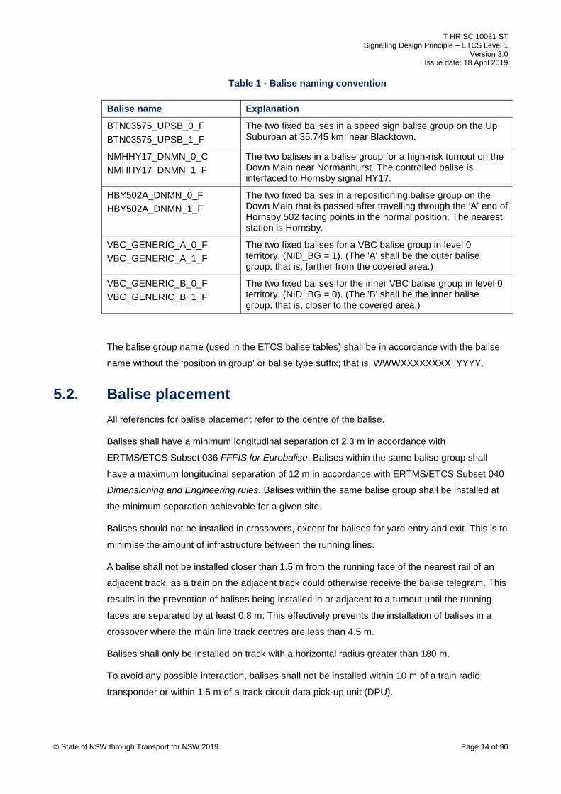
Table 1 - Balise naming convention
Balise name Explanation
BTN03575_UPSB_0_F BTN03575_UPSB_1_F
The two fixed balises in a speed sign balise group on the Up Suburban at 35.745 km, near Blacktown.
NMHHY17_DNMN_0_C NMHHY17_DNMN_1_F
The two balises in a balise group for a high-risk turnout on the Down Main near Normanhurst. The controlled balise is interfaced to Hornsby signal HY17.
HBY502A_DNMN_0_F HBY502A_DNMN_1_F
The two fixed balises in a repositioning balise group on the Down Main that is passed after travelling through the ‘A’ end of Hornsby 502 facing points in the normal position. The nearest station is Hornsby.
VBC_GENERIC_A_0_F VBC_GENERIC_A_1_F
The two fixed balises for a VBC balise group in level 0 territory. (NID_BG = 1). (The 'A' shall be the outer balise group, that is, farther from the covered area.)
VBC_GENERIC_B_0_F VBC_GENERIC_B_1_F
The two fixed balises for the inner VBC balise group in level 0 territory. (NID_BG = 0). (The 'B' shall be the inner balise group, that is, closer to the covered area.)
The balise group name (used in the ETCS balise tables) shall be in accordance with the balise
name without the ‘position in group’ or balise type suffix; that is, WWWXXXXXXXX_YYYY.
5.2. Balise placement All references for balise placement refer to the centre of the balise.
Balises shall have a minimum longitudinal separation of 2.3 m in accordance with
ERTMS/ETCS Subset 036 FFFIS for Eurobalise. Balises within the same balise group shall
have a maximum longitudinal separation of 12 m in accordance with ERTMS/ETCS Subset 040
Dimensioning and Engineering rules. Balises within the same balise group shall be installed at
the minimum separation achievable for a given site.
Balises should not be installed in crossovers, except for balises for yard entry and exit. This is to
minimise the amount of infrastructure between the running lines.
A balise shall not be installed closer than 1.5 m from the running face of the nearest rail of an
adjacent track, as a train on the adjacent track could otherwise receive the balise telegram. This
results in the prevention of balises being installed in or adjacent to a turnout until the running
faces are separated by at least 0.8 m. This effectively prevents the installation of balises in a
crossover where the main line track centres are less than 4.5 m.
Balises shall only be installed on track with a horizontal radius greater than 180 m.
To avoid any possible interaction, balises shall not be installed within 10 m of a train radio
transponder or within 1.5 m of a track circuit data pick-up unit (DPU).
© State of NSW through Transport for NSW 2019 Page 14 of 90

T HR SC 10031 ST Signalling Design Principle – ETCS Level 1
Version 3.0 Issue date: 18 April 2019
To ensure that the metal mass in fishbolts does not affect the onboard transmission equipment,
balises shall not be installed where the body of the balise is within a 0.3 m longitudinal distance
from a fishplate.
Balises should not be placed in tunnels, bridges, viaducts or platforms.
5.2.1. Controlled balises near replacement points Controlled balises shall not be installed less than 5.0 m in rear of the replacement point of the
connected signal, as the balise could otherwise be read after the signal is replaced.
Where a train is required to stop close to a signal, then one of the following special
arrangements are required:
• relocating the replacement point (with or without relocating the signal)
• placing the controlled balise closer to the replacement point and providing additional
controls to maintain the correct balise information as the train passes the replacement point
without affecting the operation of the signal
Refer to T HR SC 00003 ST Circuit Design Standard – ETCS Level 1 Interface Circuits.
The replacement point of the signal shall be deemed to be one of the following:
• the insulated rail joint or the one farther in advance where there is a stagger
• 3.5 m in advance of the first tuning unit connection (tuned loops >19 m)
• The tuned bond connection (tuned loops 19 m or less)
• the axle counter head
• the centre of the DPU
5.2.2. Balises near signals
Balises for ETCS trainstops shall not be installed greater than 8.9 m in rear of the signal, as the
balise can otherwise be read before the train stops at the signal. This is based on a train
stopping with its coupling face at a minimum of 5.0 m from the signal, in addition to the position
and reading range of the onboard antenna.
Balises (controlled) at platform departure signals should be installed in advance of all
operational stopping locations. Operational stopping locations are typically the car markers, if
they exist, or the platform railing.
Balises at outer signals used for protecting high-risk turnouts and high-risk overruns should not
be installed greater than 8.9 m in rear of the signal. This allows for a less restrictive speed
profile to be transmitted for a train waiting at the signal if the protecting signal in advance clears,
or the home signal of the turnout clears for the straight route. It is permissible for these balises
© State of NSW through Transport for NSW 2019 Page 15 of 90

T HR SC 10031 ST Signalling Design Principle – ETCS Level 1
Version 3.0 Issue date: 18 April 2019
to be installed greater than 8.9 m in rear of the signal to achieve the correct braking distance or
to minimise cable trenching costs.
For future proving of full supervision (FS) applications, the fixed balise associated with balise
groups that are interfaced to a signal, shall be located in advance of the controlled balise, but no
closer than 1 m to 3 m from the signal. The controlled balise shall be typically placed 2 m to 3 m
from the signal.
5.2.3. Guard rails and derailment plinths Balises should not be placed within the following:
• derailment plinths
• between guard rails
• within angle iron guard rails
To ensure both cross-talk protection and reliable transmission, guard rails at balises shall be
provided with a special purpose insulated joint.
Balises between guard rails shall be installed longitudinally. This requirement prevents balises
being installed between guard rails where the horizontal track radius is less than 300 m.
Refer to ERTMS/ETCS Subset-036 and SPG 0706 Installation of Trackside Equipment.
6. Data functions The telegram transmitted by a balise consists of a balise header and a series of packets.
Each balise group function requires certain packets to be transmitted. The packets used are
shown in Table 2.
Table 2 – Packets used
Packet number Packet name
0 VBC cover marker
3 National values
5 Linking
6 VBC order
12 Level 1 movement authority (MA)
16 Repositioning information
21 Gradient information
27 International static speed profile (SSP)
41 Level transition order
65 Temporary speed restriction (TSR)
67 Track condition: big metal masses
© State of NSW through Transport for NSW 2019 Page 16 of 90

T HR SC 10031 ST Signalling Design Principle – ETCS Level 1
Version 3.0 Issue date: 18 April 2019
Packet number Packet name
72 Plain text messages
80 Mode profile
132 Danger for shunting information
137 Stop if in staff responsible (SR)
180 LSSMA display toggle order
181 Generic LS function marker
254 Default balise, loop or RIU information
255 End of information
Refer to ERTMS/ETCS Subset-026-7 System Requirements Specification – Chapter 7 –
ERTMS/ETCS language for packet syntax and ERTMS/ETCS Subset-026-8 System
Requirements Specification – Chapter 8 – Messages for balise header syntax.
Certain figures in this document show packet information for balise group messages. For
completeness, all packets transmitted are shown, excluding packet #255, which is transmitted
as a finishing flag for every telegram. Packet information that is pertinent to the particular balise
group function is shown in boldface within the figures.
6.1. Confidence interval The onboard computer’s estimated position of an announced balise group may not be at its
actual position, mainly due to inaccuracies in the odometer. The actual position can be up to
one half of the confidence interval distance, either side of the estimated position.
For any trackside design calculation that requires an estimation of the confidence interval (CI), it
shall be assumed as:
CI = 2 x (5% * distance travelled + 5 m + Q_LOCACC)
Distance travelled refers to the estimated position of the train front from the last balise group
used for location reference.
Q_LOCACC refers to the location accuracy of the last balise group used for location reference.
The value of Q_LOCACC shall comply with Section 6.2.2.
6.2. Linking Linking is the announcement of balise groups in advance. The aim of linking is to:
• determine whether a balise group has been missed or not found within the expectation
window and take the appropriate action
• assign a coordinate system to balise groups consisting of a single balise
• correct the confidence interval due to odometer inaccuracy © State of NSW through Transport for NSW 2019 Page 17 of 90

T HR SC 10031 ST Signalling Design Principle – ETCS Level 1
Version 3.0 Issue date: 18 April 2019
Refer to ERTMS/ETCS Subset-026-3System Requirements Specification – Chapter 3 –
Principles for more information.
6.2.1. Q_LINK qualifier
The balise header contains the data variable Q_LINK, applicable to both directions, which
marks the balise group as linked (Q_LINK=1) or unlinked (Q_LINK=0).
Balise groups marked as unlinked are always processed by the onboard computer.
When linking information is used onboard, the following balise groups shall be taken into
account:
• balise groups that are marked as linked and included in the linking information
• balise groups marked as unlinked
When no linking information is used onboard, all balise groups shall be taken into account.
All balises shall be marked as linked (Q_LINK=1) except for TSW balise groups and those for
yard entry and exit.
6.2.2. Packet #5 Packet #5 is used for linking to balise groups in advance.
In the signalled direction, all balise groups shall be linked to (by the balise group(s) in the rear),
with the following exceptions:
• unlinked (Q_LINK=0) balise groups
• big metal mass announcement balise groups in level 0 territory
• level 0 to level 1 transition announcement balise groups
© State of NSW through Transport for NSW 2019 Page 18 of 90

T HR SC 10031 ST Signalling Design Principle – ETCS Level 1
Version 3.0 Issue date: 18 April 2019
For a balise group that transmits linking (packet #5), it shall link to two balise groups that are
marked as linked. Exceptions to this requirement are as follows:
• Balise groups in rear of an ETCS trainstop balise group shall not link to a balise group in
advance of this ETCS trainstop balise group. This is because the stored linking information
is deleted from the onboard computer if a service brake linking reaction occurs as a result
of the ETCS trainstop balise group being missed.
• When a linked balise group is announced as an unknown balise group, no further balise
group is required to be linked, by definition the next balise group is not known from the
balise group sending the linking (packet #5).
In the unsignalled direction, only the following balise groups shall be linked to:
• both balise groups announcing a level crossing
Approaching a level crossing in the wrong running direction, the balise group prior to the
balise groups protecting the crossing in the wrong running direction shall link to both balise
groups. In the wrong running direction of travel, the first balise group protecting the
crossing shall link to the second balise group.
• the first (or only) wrong running entry balise group
The exception to this is where the approach to the wrong running entry balise group is after
a trip order, such as from an ETCS trainstop at a fixed red signal.
Yard balise groups cannot perform linking as they are marked as unlinked.
A value of 5 m shall be allocated to the data variable Q_LOCACC for all balise groups, except
for those used for calibration purposes approaching buffer stops (that is balises placed 40 m
from the end of authority (EOA), which shall have a value of 3 m allocated to Q_LOCACC.
6.2.3. Reaction For a balise group that is linked (from a balise group in rear), it is expected to be read within the
expectation window. This distance is calculated by the onboard computer. The expectation
window is based on the distance to the balise group (assigned to the data variable D_LINK) and
the confidence interval. If a balise group that is linked has an inconsistent balise group message
or is not detected, then a linking reaction occurs. The type of reaction is defined by the data
variable Q_LINKREACTION.
When linking to an ETCS trainstop associated with a signal, or a fixed red, or permanent stop
sign, the linking reaction shall command a service brake. When linking to all other balise
groups, the linking reaction shall be 'no reaction' for the first balise group referred to in the
linking information; however, the onboard equipment will be configured such that a message
appears on the driver machine interface (DMI). The linking reaction shall be 'service brake
reaction' for the second balise group referred to in the linking information.
© State of NSW through Transport for NSW 2019 Page 19 of 90

T HR SC 10031 ST Signalling Design Principle – ETCS Level 1
Version 3.0 Issue date: 18 April 2019
6.2.4. Repositioning
At facing points, it is not always possible to know which balise group to link to. Therefore, a
special value for an unknown identity is used in the linking information. A balise group that links
to an unknown identity is termed ‘repositioning announcement balise group’. The repositioning
announcement function does not require a dedicated balise group. The function shall be
combined with the balise group that is first in rear of the facing points.
The first balise group in advance of facing points (in each position) is termed 'repositioning
balise group'. It contains packet #16.
The D_LINK distance in the repositioning announcement balise group shall be the distance to
the farthest repositioning balise group.
The expectation window for repositioning extends from the last repositioning announcement
balise group until the minimum safe front end of the train has passed the last possible location
of the repositioning balise group, taking the antenna position into account. Refer to
ERTMS/ETCS Subset-026-3 for more information.
For the purposes of balise placement (taking into account the repositioning expectation
window), the minimum distance between the repositioning announcement balise group and the
balise group in advance of the repositioning balise group, shall be calculated using the following
formula:
© State of NSW through Transport for NSW 2019 Page 20 of 90
Only one linked balise group shall be passed in the minimum distance calculated.
Refer to AMS Project Specifications – ATP Design Guideline for Repositioning Expectation
Window for more information.
In the signalled direction, repositioning shall be used for all facing turnouts regardless of
whether there are signalled moves through both point positions and if the balise group that will
be passed next is known. This solution minimises the signalling interface and provides a simple
and consistent method.
Note: This application of repositioning differs in part from the ERA intent, in so far as
repositioning is not used to provide an extension to the movement authority (MA).
Repositioning is not required where there is no requirement for linking. For example, there is no
requirement to link to a yard balise group. Repositioning is not required where there is no balise
group through one of the turnout positions. For example, there is no requirement for
repositioning for a turnout to a line not fitted with ETCS.
In the unsignalled direction, repositioning shall only be provided where there is a requirement
for linking.

T HR SC 10031 ST Signalling Design Principle – ETCS Level 1
Version 3.0 Issue date: 18 April 2019
The repositioning balise groups that are linked from a given repositioning announcement balise
group shall all have the same orientation; however, the orientation may be different to the
repositioning announcement balise groups, such as where the Up and Down directions change
at a facing junction, for example at a triangle.
A dedicated repositioning balise group may be required on the fork that has the change of
direction, such as where repositioning is combined with a balise group of the opposite nominal
direction.
As a repositioning balise group cannot contain a movement authority (MA) for the same
direction, a repositioning balise group cannot be combined with another function that requires
an MA for the same direction. As a mode profile is always accompanied by an MA, a
repositioning balise group cannot be combined with another function that requires a mode
change for the same direction. In other words, packet #16 cannot be combined in a balise group
that has packet #12 or packet #80 for the same direction.
A balise group used for initiating target speed monitoring (TSM) shall not contain repositioning
information for the same direction. This is to ensure that a train travelling in staff responsible
(SR) mode is transitioned to limited supervision (LS) mode when approaching a hazard. This
requirement does not apply to redundant TSM balise groups.
Thus a repositioning balise group cannot be combined with the following functions for the same
direction:
• ETCS trainstops
• TSM-initiating balise groups (for buffer stops, high-risk speed signs, high-risk turnouts,
high-risk overruns and wrong running level crossings)
• buffer stop balise groups
• buffer stop redundant TSM balise groups
• mode change balise groups providing an early change to LS mode after a train turns back
See Section 7.8.1 where a repositioning balise group is required to be used as a wrong running
entry balise group. See Section 7.8.2 where a repositioning balise group is required to be used
as a wrong running exit balise group.
Repositioning for low-risk turnouts
For a low-risk turnout, the repositioning balise group on the diverging line typically transmits the
new line speed. The preferred position is as close as possible (up to 10 m) in advance of the
end of the (last) turnout or crossover. See Figure 1.
© State of NSW through Transport for NSW 2019 Page 21 of 90

T HR SC 10031 ST Signalling Design Principle – ETCS Level 1
Version 3.0 Issue date: 18 April 2019
60 X60
90
80confidence
interval
D_LINK distance
minimum distance
repositioning announcement
balise group
repositioning balise groups
< 10 m preferred160 m maximum
Fixed baliseLegend
Q_LOCACC Q_LOCACC
1.3m
Figure 1 – Repositioning – low-risk turnout through a crossover
A position that is less than 160 m in advance of the end of the (last) turnout or crossover is
permitted to allow the repositioning function to be combined in a balise group performing
another function. See Figure 2.
X60
50< 160 m
Fixed baliseLegend
80confidence
interval
repositioning balise groups
Q_LOCACC Q_LOCACC
1.3m
D_LINK distance
minimum distance
60repositioning
announcement balise group
© State of NSW through Transport for NSW 2019 Page 22 of 90
Figure 2 – Repositioning – low-risk turnout to a refuge line
The 160 m maximum distance avoids the operational restriction of providing a line speed
update after the rear of a typical 8-car EMU has cleared the points. A position greater than
160 m is permitted if there is no speed difference on the diverging line.
The end of a crossover is assumed to be at the toe of the trailing end. The end of a turnout is
assumed to be at the first insulated joint past the clearance point.
Apart from the expectation window requirements and those described in Section 5.2, the
repositioning balise group on the non-diverging line has no specific positioning requirements.
The repositioning function will typically be combined in a balise group performing another
function.

T HR SC 10031 ST Signalling Design Principle – ETCS Level 1
Version 3.0 Issue date: 18 April 2019
Repositioning for high-risk turnouts
For a high-risk turnout, the repositioning balise groups shall toggle-off the display of the LSSMA
when required and typically transmit line speed.
The repositioning balise group on the diverging line shall be in advance of the end of the turnout
or crossover. The preferred position is 160 m in advance of the end of the last turnout or
crossover. The position may be up to 200 m in advance of the end of the last turnout or
crossover. The position is not as critical as a low-risk turnout, as the diverging line speed is
typically sent as an iteration by the repositioning announcement balise group. See Section 8.3.2
for more information on when the diverging line speed is sent.
The 160 m and 200 m distances aim to minimise the operational restriction for EMUs, consisting
of 8 cars and 10 cars respectively. The line speed update minimises the operational restriction
in the situation where the diverging line speed has not been sent by the repositioning
announcement balise group and the repositioning balise group has been missed.
The repositioning balise group on the non-diverging line shall be in advance of the turnout and
as close to the turnout as possible.
6.3. ETCS onboard equipment modes Refer to T HR SC 01650 SP ETCS Onboard Equipment for details specific to the onboard
subsystem.
6.3.1. Modes used Where a mode transition is ordered from the trackside subsystem, the mode transition is
achieved by transmitting packet #80, which contains the mode profile associated with an MA.
Refer to ETRMS/ETCS Subset-026-4 System Requirements Specification – Chapter 4 – Modes
and Transitions for a full description of all mode transitions and the conditions required for each
transition.
This section describes the following:
• the modes used by the onboard equipment
• some of the common mode transitions
• details specific to the trackside subsystem
Limited supervision
LS is the desired mode on running lines for both signalled and unsignalled moves. The LS
mode cannot be selected by the driver. The order to change to LS mode shall be transmitted
whenever an MA is transmitted for a given direction.
© State of NSW through Transport for NSW 2019 Page 23 of 90

T HR SC 10031 ST Signalling Design Principle – ETCS Level 1
Version 3.0 Issue date: 18 April 2019
After a train has been tripped, re-entering LS mode cannot be achieved until a valid message is
received from a balise group that transmits an MA and the order to change to LS mode for the
applicable direction.
In LS mode, balise groups shall transmit the maximum network speed of 160 km/h for the
V_MAMODE variable in packet #80, except for wrong running situations. See Section 7.8 for
details.
Trip
Trip (TR) mode commands the emergency brake.
Post trip
Post trip (PT) mode can be entered from TR mode if certain conditions are met, including the
train being at a standstill. PT mode releases the emergency brake command.
Staff responsible
SR mode allows drivers to move trains under their own responsibility.SR mode is proposed by
the onboard from PT mode when restarted unless driver selects shunting. SR mode is also
used after the onboard equipment starts-up. A train is required to be in SR mode before it exits
an ETCS-protected yard. Speed is limited by the SR mode speed limit (V_NVSTFF) of 40 km/h.
Shunting
Shunting (SH) is the desired mode for movements within yards where speed is limited by the
SH mode speed limit (V_NVSHUNT) of 25 km/h. The order to change to SH mode shall be
transmitted when entering an ETCS protected yard. Operational procedures specify that SH
mode should be manually selected by the driver for amalgamating, dividing or setting back, if
not already in SH mode.
Other modes used are as follows:
• sleeping (SL)
• non-leading (NL)
• isolation (IS)
• system failure (SF)
• standby (SB)
• unfitted (UN)
© State of NSW through Transport for NSW 2019 Page 24 of 90
T HR SC 10031 ST Signalling Design Principle – ETCS Level 1
Version 3.0 Issue date: 18 April 2019
6.3.2. Modes not used
The following modes are not used:
• full supervision(FS)
• on sight (OS)
• national system (SN)
• reversing (RV)
• passive shunting (PS)
6.3.3. Stop if in SH mode Certain balise group functions transmit packet #132, which contains the ‘Danger for Shunting’
information. This packet transmits the ‘Stop if in SH mode’ order to trip the train if in shunting
mode.
6.3.4. Stop if in SR mode Certain balise group functions transmit packet #137, which contains the ‘Stop if in Staff
Responsible’ information. This packet transmits the ‘Stop if in SR mode’ order to trip the train if
in SR mode.
6.4. Movement authorities Packet #12 contains the MA. The data shall treat the MA as a single section.
The section length of all movement authorities shall be of the maximum value allowed in the
data, with the following exceptions:
• ETCS trainstop balise groups when transmitting a trip order
• buffer stop balise groups
• buffer stop TSM-initiating balise groups
• buffer stop redundant TSM balise groups
The order to change to level 1 (using packet #41) and the order to change to LS mode (using
packet #80) shall be transmitted whenever an MA is transmitted for a given direction.
Balise groups in a level 0 area shall not transmit an MA, unless announcing a transition to
level 1. Balise groups transmitting an immediate transition order to level 0 shall not transmit an
MA for the same direction.
© State of NSW through Transport for NSW 2019 Page 25 of 90
T HR SC 10031 ST Signalling Design Principle – ETCS Level 1
Version 3.0 Issue date: 18 April 2019
6.5. Gradient Packet #21 contains gradient information and is transmitted for the applicable direction from the
following balise groups:
• those transmitting packet #12 for the same direction
• redundant TSM balise groups
• TSM-initiating balise groups
Each gradient section shall be expressed as per mile (‰), safely rounded down to the nearest
integer. For example, a 1.43% rising grade would be expressed as 14‰, and a 1.43% falling
grade would be expressed as 15‰.
The gradient of the line shall be transmitted when the onboard computer is required to calculate
a TSM braking curve. The default gradient of 35‰ shall be transmitted otherwise.
The vertical alignment database (VAD) and survey alignment database (SAD) shall be the
source of gradient information (where provided by the rail infrastructure manager (RIM)). For a
section containing a vertical curve (easement), the VAD shows the section split in two, with
each half becoming part of the adjoining gradient section. This approach shall also be used for
gradient information that cannot be sourced from the VAD.
Note: This requirement differs from ERTMS/ETCS Subset-026-3.
Gradient information shall be provided to cover the permitted braking distance plus 20% of the
permitted braking distance, ending at the farthest target point, to allow for the onboard
equipment to accurately calculate the TSM braking curve.
Where the approach to a target point traverses a crossover, the gradient for the crossover shall
be assumed to be the lower of the lines. The term 'lower gradient' implies a lower per mille
value. For example, 3‰ is lower than 2‰.
The braking tool has a maximum of 10 gradient sections. If there are more than ten sections of
gradient over the required distance, then a gradient simplification process shall be followed to
reduce the number to no more than 10. An iterative process may be required as the braking tool
results and the gradient simplification results are dependent upon each other.
To limit the amount of data transmitted, a maximum of 10 gradient sections shall be used for the
calculation of the braking curve.
© State of NSW through Transport for NSW 2019 Page 26 of 90

T HR SC 10031 ST Signalling Design Principle – ETCS Level 1
Version 3.0 Issue date: 18 April 2019
6.5.1. Gradient simplification
The steps for gradient simplification shall be applied in the following order until there are no
more than 10 gradient sections. Within step 2 and step 4, the simplification is to be applied in
the order of travel. The steps are as follows:
If two consecutive gradient entries have the same value, then the gradients shall be combined
and treated as one entry.
For a gradient section of less than 150 m adjoining a lower gradient section at one end, the
section shall be assumed to be part of the lower gradient section.
For a gradient section of less than 150 m adjoining lower gradient sections at both ends,
the section shall be assumed to be part of the section with the higher gradient of the two.
The initial sections shall be combined and assumed to have a gradient of the lowest of these
sections, and assumed to end at a point where the emergency brake deceleration (EBD) curve
is 10 km/h above the line speed.
Step 2 shall be repeated, without the 150 m constraint.
For a detailed gradient simplification process, refer to Advanced train control Migration System
(AMS) Specifications - Gradient Simplification Design Guideline.
6.6. Target speed monitoring TSM is where train speed is supervised to an onboard calculated braking curve, braking to a
target speed at a target point. The TSM target information is transmitted by balise groups in rear
of the target.
TSM shall be used when approaching buffer stops, high-risk speed signs, high-risk turnouts,
high-risk overruns and wrong running level crossings. All possible approaches to these hazards
shall be considered.
6.6.1. Redundancy The TSM target information shall be sent from two balise groups to provide redundancy.
To avoid the TSM information associated with the target being omitted due to both balise
groups being missed, the balise groups sending the TSM information shall be consecutive to
provide a fail-safe solution.
The first transmission is for redundancy purposes, providing a fail-safe solution for these high-
risk locations if the second transmission is missed. This first transmission is typically transmitted
from a balise group provided for another purpose. The balise group is termed the ‘redundant
TSM balise group’. A dedicated balise group may be necessary in certain layouts, for example
where the target point is in advance of a facing turnout.
© State of NSW through Transport for NSW 2019 Page 27 of 90

T HR SC 10031 ST Signalling Design Principle – ETCS Level 1
Version 3.0 Issue date: 18 April 2019
This redundant TSM shall be transmitted regardless of the signalling controls and can be
transmitted from a fixed balise group. It shall be the most restrictive TSM associated with the
hazard.
The redundant TSM balise group shall include any high-risk speed signs and any intermediate
speed increases; however, the redundant TSM balise group shall not include any intermediate
low risk speed reductions. The inclusion of intermediate speed increases in the redundant TSM
balise group will ensure that the train can operate at line speed even if the TSM initiating balise
group is missed.
The second transmission is from a balise group termed the ‘TSM-initiating balise group’. One
balise in this balise group shall be controlled by an LEU if the TSM is dependent upon signalling
controls.
6.6.2. Lowest supervised speed within the movement authority The display to the driver of the LSSMA is toggled on or off by the use of packet #180.
Packet #181 shall always accompany packet #180, enabling this toggling.
The toggle-off order shall be transmitted by all balise groups, except for the following
circumstances:
• LSSMA shall be toggled on at a controlled balise group (excluding the redundant balise
group) protecting a high-risk overrun or turnout, if the signal aspect information provided to
the LEU cannot positively identify whether the protecting/home signal is clear for the
straight or turnout route
• where it is possible that a cascading function requires the display of the LSSMA to remain
toggled on
The LSSMA shall not be displayed for a high-risk converging junction, as TSM is always
applied.
On an approach that includes a turnout or crossover, the design shall ensure that the LSSMA
speed displayed to the driver is not higher than the turnout speed on the approach.
After traversing a high-risk turnout, the display of the LSSMA is to remain toggled on until
passing the repositioning balise group.
For a high-risk overrun, the display of the LSSMA is to remain toggled on until passing the
balise group associated with the protecting signal or has been toggled off by a balise group
provided on the approach to revoke a TSM (once the signal aspect clears). The toggle off order
shall be transmitted by a balise group up to 8.9 m in rear of, or up to 10 m in advance of the
protecting signal. The balise group shall be fixed unless the toggle off function is combined with
a function requiring a controlled balise group.
© State of NSW through Transport for NSW 2019 Page 28 of 90

T HR SC 10031 ST Signalling Design Principle – ETCS Level 1
Version 3.0 Issue date: 18 April 2019
6.6.3. Braking tool
The braking tool is a customised version of the ERA braking curves tool. The ERA publishes an
accompanying handbook for this tool.
The braking tool has been customised by applying the following:
• service brake
o deceleration rate of 0.55 ms-2 (based on the C set and K set)
o brake delay of 3.6 seconds (based on the K set)
• emergency brake
o deceleration rate of 0.6 ms-2 (derived from the GE52 braking curve)
o brake delay of 3.85 seconds (based on the M set)
The 'permitted distance' results given by the braking tool shall be used as an input for all TSM
design. The TSM-initiating balise group shall not be closer to the target point than this permitted
distance.
Buffer stops shall use the EOA or supervised location (SvL) option with fixed release speed. All
other TSM calculations shall use the 'LOA/MRSP' (limit of authority or most restrictive speed
profile) option.
The location accuracy of all ‘relocation balises’ shall be 5 m unless otherwise stated. Refer to
ERTMS/ETCS Subset-026-3 for the balises that are considered as relocation balises.
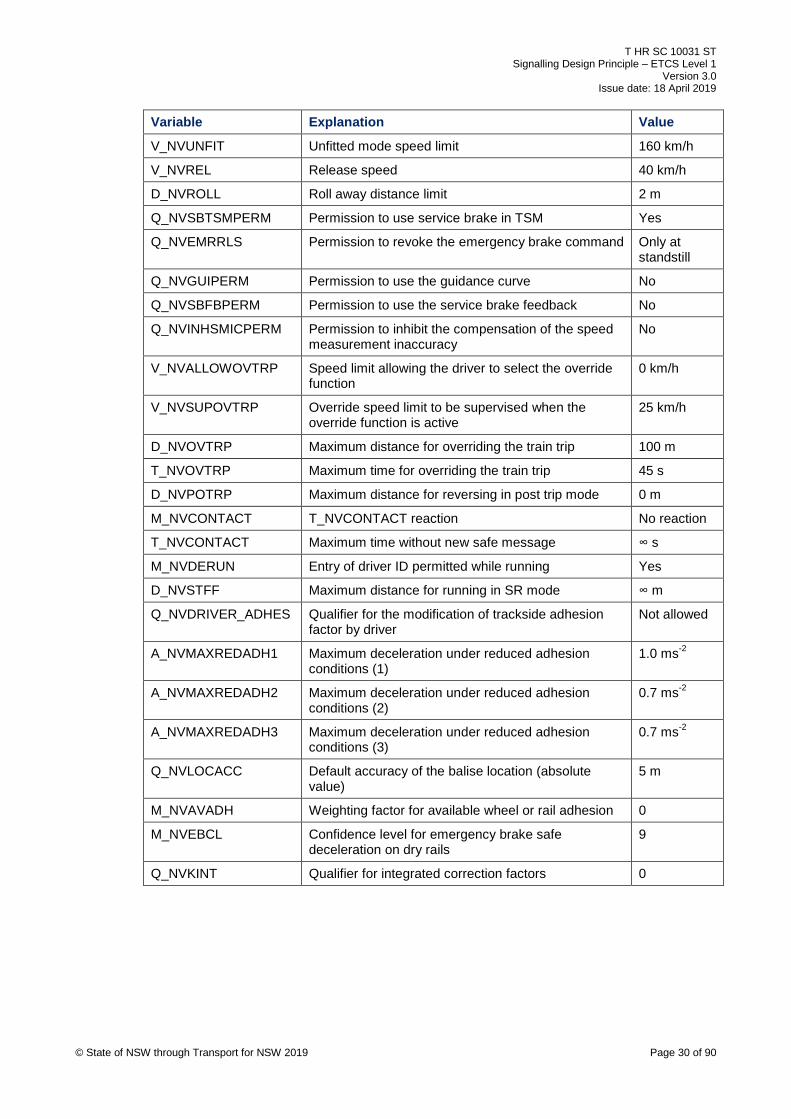
6.7. National values National values are variables applicable to the whole network. Packet #3 contains the national
values.
National values shall be transmitted for movements in both directions at all yard balise groups,
and at all level transition announcement and border balise groups. The values shall be
applicable immediately when received.
Table 3 specifies the applicable national values.
Table 3 - National values
Variable Explanation Value
NID_C Identity number of the country or region 540
V_NVSHUNT SH mode speed limit 25 km/h
V_NVSTFF SR mode speed limit 40 km/h
V_NVONSIGHT On sight mode speed limit 30 km/h
V_NVLIMSUPERV LS mode speed limit 40 km/h
© State of NSW through Transport for NSW 2019 Page 29 of 90
T HR SC 10031 ST Signalling Design Principle – ETCS Level 1
Version 3.0 Issue date: 18 April 2019
Variable Explanation Value
V_NVUNFIT Unfitted mode speed limit 160 km/h
V_NVREL Release speed 40 km/h
D_NVROLL Roll away distance limit 2 m
Q_NVSBTSMPERM Permission to use service brake in TSM Yes
Q_NVEMRRLS Permission to revoke the emergency brake command Only at standstill
Q_NVGUIPERM Permission to use the guidance curve No
Q_NVSBFBPERM Permission to use the service brake feedback No
Q_NVINHSMICPERM Permission to inhibit the compensation of the speed measurement inaccuracy
No
V_NVALLOWOVTRP Speed limit allowing the driver to select the override function
0 km/h
V_NVSUPOVTRP Override speed limit to be supervised when the override function is active
25 km/h
D_NVOVTRP Maximum distance for overriding the train trip 100 m
T_NVOVTRP Maximum time for overriding the train trip 45 s
D_NVPOTRP Maximum distance for reversing in post trip mode 0 m
M_NVCONTACT T_NVCONTACT reaction No reaction
T_NVCONTACT Maximum time without new safe message ∞ s
M_NVDERUN Entry of driver ID permitted while running Yes
D_NVSTFF Maximum distance for running in SR mode ∞ m
Q_NVDRIVER_ADHES Qualifier for the modification of trackside adhesion factor by driver
Not allowed
A_NVMAXREDADH1 Maximum deceleration under reduced adhesion conditions (1)
1.0 ms-2
A_NVMAXREDADH2 Maximum deceleration under reduced adhesion conditions (2)
0.7 ms-2
A_NVMAXREDADH3 Maximum deceleration under reduced adhesion conditions (3)
0.7 ms-2
Q_NVLOCACC Default accuracy of the balise location (absolute value)
5 m
M_NVAVADH Weighting factor for available wheel or rail adhesion 0
M_NVEBCL Confidence level for emergency brake safe deceleration on dry rails
9
Q_NVKINT Qualifier for integrated correction factors 0
© State of NSW through Transport for NSW 2019 Page 30 of 90

T HR SC 10031 ST Signalling Design Principle – ETCS Level 1
Version 3.0 Issue date: 18 April 2019
6.8. Data variables The data variables shall be set as indicated in Table 4.
Table 4 - Data variables
Variable Explanation Value
Q_SCALE Qualifier for the distance scale 1 m
Q_UPDOWN Balise telegram transmission direction Up link telegram
M_VERSION Version of ETCS system 2.0
Q_MEDIA Qualifier to indicate the type of media Balise
M_DUP Duplicate balise No duplicates
V_MAIN Signalling related speed restriction (where there is no trip)
160 km/h
V_LOA Permitted speed at the limit of authority (where there is no trip or not approaching a buffer stop)
160 km/h
V_LOA Permitted speed at the limit of authority (trip order or approaching a buffer stop)
0 km/h
T_LOA Validity time for the target speed at the limit of authority (where there is no trip or not approaching a buffer stop)
∞ s
T_LOA Validity time for the target speed at the limit of authority (trip order or approaching a buffer stop)
0 s
Q_DANGERPOINT Qualifier for danger point description (not approaching a buffer stop)
0
Q_DANGERPOINT Qualifier for danger point description (approaching a buffer stop)
1
Q_ENDTIMER Qualifier to indicate whether end section timer information exists for the end section in the MA
0
Q_OVERLAP Qualifier to tell whether there is an overlap 0
L_SECTION Length of section in the MA (in a repositioning balise group not in advance of a buffer stop TSM-initiating balise group)
32767 m
L_SECTION Length of section in the MA (in a repositioning balise group in advance of a buffer stop TSM-initiating balise group)
Distance to EOA
L_ACKMAMODE Length of the acknowledgement area in rear of the start of the required mode
0 m
L_MAMODE Length of the area of the required mode Infinite length
Q_MAMODE Qualifier to indicate the supervision of the beginning of the mode profile
0
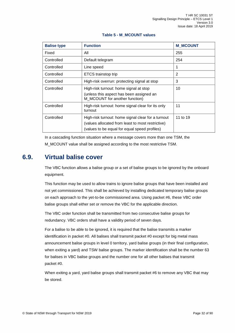
The data variable for the message counter, M_MCOUNT shall have values assigned as
indicated in Table 5.
© State of NSW through Transport for NSW 2019 Page 31 of 90
T HR SC 10031 ST Signalling Design Principle – ETCS Level 1
Version 3.0 Issue date: 18 April 2019
Table 5 - M_MCOUNT values
Balise type Function M_MCOUNT
Fixed All 255
Controlled Default telegram 254
Controlled Line speed 1
Controlled ETCS trainstop trip 2
Controlled High-risk overrun: protecting signal at stop 3
Controlled High-risk turnout: home signal at stop (unless this aspect has been assigned an M_MCOUNT for another function)
10
Controlled High-risk turnout: home signal clear for its only turnout
11
Controlled High-risk turnout: home signal clear for a turnout (values allocated from least to most restrictive) (values to be equal for equal speed profiles)
11 to 19
In a cascading function situation where a message covers more than one TSM, the
M_MCOUNT value shall be assigned according to the most restrictive TSM.
6.9. Virtual balise cover The VBC function allows a balise group or a set of balise groups to be ignored by the onboard
equipment.
This function may be used to allow trains to ignore balise groups that have been installed and
not yet commissioned. This shall be achieved by installing dedicated temporary balise groups
on each approach to the yet-to-be commissioned area. Using packet #6, these VBC order
balise groups shall either set or remove the VBC for the applicable direction.
The VBC order function shall be transmitted from two consecutive balise groups for
redundancy. VBC orders shall have a validity period of seven days.
For a balise to be able to be ignored, it is required that the balise transmits a marker
identification in packet #0. All balises shall transmit packet #0 except for big metal mass
announcement balise groups in level 0 territory, yard balise groups (in their final configuration,
when exiting a yard) and TSW balise groups. The marker identification shall be the number 63
for balises in VBC balise groups and the number one for all other balises that transmit
packet #0.
When exiting a yard, yard balise groups shall transmit packet #6 to remove any VBC that may
be stored.
© State of NSW through Transport for NSW 2019 Page 32 of 90

T HR SC 10031 ST Signalling Design Principle – ETCS Level 1
Version 3.0 Issue date: 18 April 2019
7. Fixed balise group functions A fixed balise group is a balise group that always transmits the same message; that is, the
message is not dependent upon any signalling controls and thus an LEU is not required. The
functions described in this section, in addition to repositioning and LSSMA toggle off, shall be
implemented using fixed balise groups, except where these functions can be combined with
other functions requiring a controlled balise group.
7.1. Level transitions Level transitions shall be provided between level 0 and level 1 territory.
The electrified areas not fitted with ETCS are defined as level 0 territory. This includes the areas
not yet fitted, in addition to the electrified portions of metropolitan freight lines. The only balise
groups used in level 0 territory are for big metal masses, TSW signs, VBC orders and
announcement of level transitions.
All balise groups that transmit a MA shall also transmit an immediate level transition order.
Packet #41 contains the level transition information.
7.1.1. Level transition borders Level transition borders exist where level 0 territory meets level 1 territory.
A balise group shall be placed at the level transition border. The first balise in the direction of
travel (N_PIG 0) shall be placed within 3 m of the level transition border. It shall transmit an
immediate level transition, achieved by the data variable D_LEVELTR assigned the value of
32767. The order to change to level 1 shall additionally be transmitted by other balise groups
whenever an MA is transmitted for a given direction.
On a unidirectional line, the level transition balise group shall transmit a level 1 transition for one
direction and a level 0 transition for the other. Figure 3 shows an example of this arrangement.
© State of NSW through Transport for NSW 2019 Page 33 of 90

T HR SC 10031 ST Signalling Design Principle – ETCS Level 1
Version 3.0 Issue date: 18 April 2019
© State of NSW through Transport for NSW 2019 Page 34 of 90
Figure 3 - Level transition

T HR SC 10031 ST Signalling Design Principle – ETCS Level 1
Version 3.0 Issue date: 18 April 2019
On a single line or bidirectional line, the Up and Down level transition borders should coincide or
be placed in close proximity. If the borders coincide, then this reduces the number of balises
required. If the borders are in close proximity, then this aids drivers’ route knowledge.
In the case of multiple lines, the level transition borders for each line should be in close
proximity to aid drivers’ route knowledge.
Where the level 0 and level 1 border transitions do not coincide on a given line, the 'BEGIN
ATP' and 'END ATP' signs shall be placed adjacent to their relevant reference balise. Where the
transitions coincide, the back-to-back 'BEGIN ATP' and 'END ATP' signs shall be placed
adjacent to the reference balise, with the primary purpose of the balise group deemed to be for
the normal running direction.
The location of level transition borders should be chosen where the driver is less likely to be
concentrating on other critical tasks. To achieve this and to minimise certain risks associated
with the transition, the following apply for the location of level transition borders:
• level transition borders should be placed as follows:
o in automatic sections or outside of yard limits
o in areas with adequate sighting
o where the first signal in the level 0 area has a trip arm style trainstop
• level transition borders should not be placed as follows:
o in proximity to stations, junctions, level crossings, or any other location that may be
associated with route complexity or elevated attentional demand by the driver
o in areas where signals are closely spaced
• level transition borders shall not be placed as follows:
o in areas where if a driver fails to acknowledge a transition, it will result in the train
stopping in a tunnel, on a bridge or on a viaduct
o in areas of insufficient braking in rear of hazards requiring ETCS protection, when
entering level 1 territory
o less than 1 km in the rear of what would be deemed a high-risk speed sign, high-risk
turnout or high-risk overrun, when entering level 0 territory
To allow the driver to select either level 0 or level 1, packet #41 shall transmit the following in
addition to the immediate transition:
• for a transition from level 0 to level 1, an iteration containing level 0 as a lower priority
• for a transition from level 1 to level 0, an iteration containing level 1 as a lower priority
© State of NSW through Transport for NSW 2019 Page 35 of 90
T HR SC 10031 ST Signalling Design Principle – ETCS Level 1
Version 3.0 Issue date: 18 April 2019
7.1.2. Level transition announcement
Announcement balise groups shall be provided on both approaches to level transition borders.
The preferred position is 250 m in rear; however, it may be up to 350 m if infrastructure
constraints do not permit. The exception to this is for the level 1 to level 0 transition
announcement for the unsignalled direction. There is no positional requirement for this function.
Therefore, this function does not need a dedicated balise group, and is typically combined in the
balise group closest to the transition border.
Announcement balise groups should be placed at a speed sign, unless a speed sign is not
present in the vicinity. This allows the driver sufficient distance to react to the speed sign before
reaching the level transition. It can also allow the balise group to be reused for the speed sign in
a subsequent stage.
The announcement balise group shall transmit a distance-delayed level transition order,
providing redundancy for the level transition border balise group. The distance (D_LEVELTR)
shall be the distance from the level transition announcement balise group (N_PIG 0) to the level
transition border balise group (N_PIG 0) plus half the confidence interval. This variable aims to
minimise the likelihood that the transition acknowledgement request does not occur before the
level transition border.
7.1.3. Text messages Level transition and announcement balise groups shall transmit important, plain text messages
to be displayed to the driver. Packet #72 contains the text for the message. Driver
acknowledgment shall not be requested.
The message transmitted by the level 0 to level 1 transition announcement balise groups shall
be 'Begin ATP ahead'.
The message transmitted by the level 1 to level 0 transition announcement balise groups shall
be 'End ATP ahead'.
These level transition announcement messages shall be displayed immediately upon passing
the announcement balise groups, and shall continue to be displayed until the level changes.
The message transmitted by the level 0 to level 1 transition border balise groups shall be 'Begin
ATP'.
The message transmitted by the level 1 to level 0 transition border balise groups shall be 'End
ATP'.
These level transition border messages shall be displayed immediately upon the level change,
and shall continue to be displayed for five seconds.
© State of NSW through Transport for NSW 2019 Page 36 of 90
T HR SC 10031 ST Signalling Design Principle – ETCS Level 1
Version 3.0 Issue date: 18 April 2019
7.2. Speed signs The scope for speed signs includes all permanent track speed sign, except for the following:
• advisory speed signs
• turnout speed signs
• yards speed signs
• intermediate trainstop speed signs
• freight speed signs
A balise group shall be placed at each speed sign, except where a balise group placed at a
speed sign could unintentionally revoke TSM. For such speed signs, the speeds shall be
transmitted as a distance-delayed iteration by the TSM-initiating balise group in rear of the
speed sign.
The speed sign balise group shall preferably have the reference balise adjacent to the speed
sign. This balise may be placed up to 20 m in rear or advance of the speed sign for a speed
increase, or up to 20 m in advance for a speed decrease.
Figure 4 and Figure 5 show examples of balise groups at speed signs.
© State of NSW through Transport for NSW 2019 Page 37 of 90

T HR SC 10031 ST Signalling Design Principle – ETCS Level 1
Version 3.0 Issue date: 18 April 2019
© State of NSW through Transport for NSW 2019 Page 38 of 90
Figure 4 - Speed signs – unidirectional line

T HR SC 10031 ST Signalling Design Principle – ETCS Level 1
Version 3.0 Issue date: 18 April 2019
© State of NSW through Transport for NSW 2019 Page 39 of 90
Figure 5 - Speed signs – bidirectional lines
T HR SC 10031 ST Signalling Design Principle – ETCS Level 1
Version 3.0 Issue date: 18 April 2019
Packet #27 transmits the static speed profiles (SSPs). Three profiles shall be transmitted as
general, medium and high. All speed sign information identified in the Train Operating
Conditions (TOC) Manual and subsequent weekly notices shall be correlated with actual onsite
speed signage.
The speeds for normal, multiple unit (MU) and express passenger train (XPT) speed signs shall
be transmitted as general, medium and high profiles respectively.
The general profile shall be the ‘basic’ profile transmitted. The medium profile shall be
transmitted utilising the variables Q_DIFF=0 and NC_CDDIFF=1.The high profile shall be
transmitted utilising the variables Q_DIFF=0 and NC_CDDIFF=2. To reduce the amount of data
transmitted, medium or high speed profiles, or both, shall not be sent if they are the same speed
as a transmitted lower speed profile.
Train length delay shall not be enforced at a speed sign.
7.2.1. High-risk speed signs Speeds signs in the scope as specified in Section 7.2 are classified as either low-risk or high-
risk.
Balise groups at low-risk speed signs provide ceiling speed monitoring (CSM), where speed is
supervised without the need to brake to a target. Where a low-risk speed sign indicates a
reduction in line speed, the train is not supervised to this new line speed until the speed sign is
passed. Where there is a deemed risk of a train travelling faster than the new line speed at (or
just in advance of) the speed sign, then the speed sign is deemed high-risk, and is protected by
announcing it from a balise group in the rear, using TSM with the speed sign as the target. See
Figure 6 for an example of this arrangement.
© State of NSW through Transport for NSW 2019 Page 40 of 90

T HR SC 10031 ST Signalling Design Principle – ETCS Level 1
Version 3.0 Issue date: 18 April 2019
100
100
100
60 60 60
100
60
Speed profile
Train speed
Fixed baliseLegend
Medium speed profile
Train speed
Onboard supervised speed
100
90 80
High-risk speed signLow-risk
speed signLow-risk
speed sign
Both Directions:#0: VBC marker#12: MA Max#41: L1#180+#181: LSSMA display off / LS function markerDown Direction:#5: Linking#21: Simplified down direction gradients#27: 1st iteration – G (inc M+H) 100 km/h, 2nd iteration – G (inc M+H) 60 km/h #80: LS Mode (V_MAMODE = 160 km/h)Up Direction:#27: 160 km/h#21: Default gradient#80: LS Mode (V_MAMODE: National Value)
Both Directions:#0: VBC marker#12: MA Max#41: L1#180+#181: LSSMA display off / LS function markerDown Direction:#5: Linking#21: Simplified down direction gradients#27: 1st iteration – G 80 km/h + M 90 km/h + H 100 km/h, 2nd iteration – G (inc M+H) 60 km/h #80: LS Mode (V_MAMODE = 160 km/h)Up Direction:#27: 160 km/h#21: Default gradient#80: LS Mode (V_MAMODE: National Value)
90(If 2nd Low-risk speed sign BG fails)
Both Directions:#0: VBC marker#12: MA Max#21: Default gradient#41: L1#180+#181: LSSMA display off / LS function markerDown Direction:#5: Linking#27: G (inc M+H) 60 km/h #80: LS Mode (V_MAMODE = 160 km/h)Up Direction:#27: 160 km/h#80: LS Mode (V_MAMODE: National Value)
Balise group linking(1st iteration)
© State of NSW through Transport for NSW 2019 Page 41 of 90
Figure 6 - High-risk speed sign

T HR SC 10031 ST Signalling Design Principle – ETCS Level 1
Version 3.0 Issue date: 18 April 2019
The braking tool shall be used to determine which balise group in rear of the high-risk speed
sign becomes the TSM-initiating balise group.
Speeds signs can only be deemed high-risk if they indicate a reduction in line speed for the
medium or high profiles. The general profile does not need to be considered in determining high
risk speed signs.
A speed sign shall be deemed high-risk if there is a specified hazard within the deceleration
distance in advance of the speed sign, assuming deceleration does not start until the train is at
the speed sign. This deceleration distance shall be calculated as the distance travelled in
2 seconds at the approach line speed, plus the distance travelled to decelerate to the posted
line speed at a deceleration rate of 0.6 ms-2.
The specified hazards are as follows:
• a timed level crossing approach where over-speeding would result in a warning time less
than the minimum required
• a deemed high-risk level crossing protected by controlled signals
• a manually controlled level crossing
• a platform
If the above specified hazards do not exist in the deceleration distance, then the following shall
apply:
• The speed sign shall be deemed low-risk if the speed reduction is 17% or less.
• If the speed reduction is greater than 17% and less than 25%, then the speed sign shall be
deemed as high-risk if the track in the deceleration distance is curved horizontally. In this
context, being curved is defined as having any curve tighter than 500 m radius, or having
any curve tighter than 950 m radius if the approach line speed is greater than 115 km/h.
• If the speed reduction is greater than or equal to 25%, then the speed sign shall be
deemed high-risk.
Speed reductions shall be calculated as a percentage of the posted line speed. For example, a
reduction from an approach line speed of 100 km/h to a posted line speed of 80 km/h shall be
considered a 25% speed reduction.
The determination of turnouts and overruns as being high-risk is generally based on the
approach speed to the first warning signal protecting the hazard. For situations where a speed
sign exists between the first warning signal and the hazard, it may be possible to sufficiently
mitigate the hazard by treating the speed sign as high-risk. If this is possible, then this solution
shall be implemented, as it can be achieved by the use of fixed balise groups.
© State of NSW through Transport for NSW 2019 Page 42 of 90

T HR SC 10031 ST Signalling Design Principle – ETCS Level 1
Version 3.0 Issue date: 18 April 2019
7.2.2. Converging junctions
For a converging junction, the criteria for determining high-risk turnouts shall apply, as the
derailment risk is based upon track geometry.
The protection for a high-risk converging junction shall be according to a high-risk speed sign. A
balise group is not required at the turnout speed sign. The display of the LSSMA shall not be
toggled on.
The same protection shall apply to facing turnouts where the only main class signalled moves
are through the points in the turning out lay.
To rationalise balise placement and to ensure speed information onboard remains up-to-date,
when exiting an ETCS protected yard or traversing from an ETCS fitted line through a
convergence, the balise group before the convergence shall send an SSP containing the
following iterations:
• permitted speed prior to the convergence
• permitted speed in advance of the trailing points starting at the toe of the points
• any additional TSM in advance of the convergence (where currently not provided through
other balise groups)
Where the convergence is classified as high-risk in terms of speed difference, the SSP being
sent before the convergence shall include the convergence turnout speed.
7.2.3. Level crossing speed signs
Balise groups at level crossing speed signs shall send a speed profile that includes speed
iterations for the following:
• indicated level crossing speed on approach
• line speed prior to the level crossing speed sign (applied at the departure edge of the
crossing), to ensure a train can return to line speed as soon as possible after passing the
crossing
If the level crossing speed sign is a high-risk speed sign, the line speed at the departure edge of
the crossing shall also be sent from the redundant balise group and balise group initiating the
TSM.
Certain portions of track on the network do not have track design speeds indicated by speed
signs. These deficiencies typically occur on loop lines and where trains turn back or turnout onto
the track in the opposite direction of normal running.
© State of NSW through Transport for NSW 2019 Page 43 of 90
T HR SC 10031 ST Signalling Design Principle – ETCS Level 1
Version 3.0 Issue date: 18 April 2019
Where the track design speeds are unknown, they shall be assumed to be the following:
• If speeds are indicated in the opposite direction, then the track design speeds shall be
assumed to be the lower of either the opposite direction speeds or those on the next speed
sign in advance (which may be a turnout speed sign or an implied X25 km/h speed sign at
a converging junction). If this assumption results in speeds lower than the turnout speed
entering this portion, then a risk-based approach shall be followed.
• If speeds are not indicated in the opposite direction, then the track design speeds shall be
assumed to be the lower of either the speeds on the speed sign in rear (typically a turnout
speed sign, posted or implied) or the speeds on the speed sign in advance (which may be
a turnout speed sign, posted or implied, at a converging junction).
An assumed track design speed shall never be higher than that suitable for the existing
signalling system.
7.2.4. Temporary speed signs Temporary speed signs include the warning, caution and clearance signs for speed-restricted
areas. Where there is a requirement to protect a speed-restricted area with ETCS equipment, a
TSW balise group shall be installed at the warning sign, with the reference balise preferably
placed adjacent to the sign. See Figure 7 for an example of this arrangement.
© State of NSW through Transport for NSW 2019 Page 44 of 90
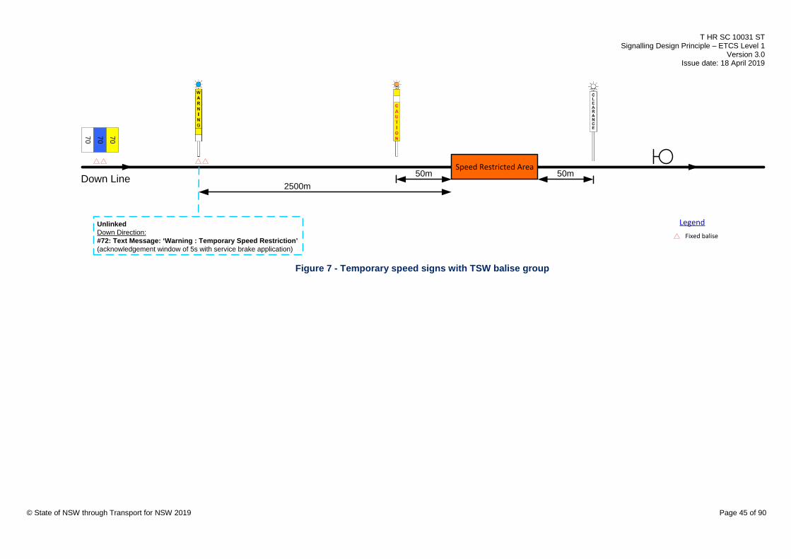
T HR SC 10031 ST Signalling Design Principle – ETCS Level 1
Version 3.0 Issue date: 18 April 2019
70 70 70
Speed Restricted Area
Fixed balise
Legend
50m2500m
UnlinkedDown Direction:#72: Text Message: ‘Warning : Temporary Speed Restriction’(acknowledgement window of 5s with service brake application)
50mDown Line
© State of NSW through Transport for NSW 2019 Page 45 of 90
Figure 7 - Temporary speed signs with TSW balise group

T HR SC 10031 ST Signalling Design Principle – ETCS Level 1
Version 3.0 Issue date: 18 April 2019
Where physical constraints exist on site and to provide a fitment tolerance to aid in the
installation, the TSW balise group may be placed as close as practicable up to 30 m in advance
of the warning sign in the direction of travel. The 30 m distance provides an adequate margin for
a train having passed the warning sign and the system alerting the driver of the temporary
speed restriction (TSR).
TSW balise groups shall transmit an important, plain text message to be displayed to the driver.
Packet #72 contains the text for the message. The message transmitted shall be 'Warning:
Temporary Speed Restriction'. The message shall be displayed immediately upon passing the
balise group and shall continue to be displayed until acknowledged by the driver. The service
brake shall be commanded if the message is not acknowledged within five seconds.
The TSW balise group shall not be placed in rear of the TSW sign to reduce the risk of a driver
being distracted when approaching the TSR.
7.3. Calibration Calibration balises are used for the purpose of resetting the confidence interval and improving
the odometer accuracy.
Where the TSM-initiating balise group for a high-risk speed sign is required greater than 2 km in
rear of the high-risk speed sign and there is no balise group that can provide calibration within
that distance, a calibration balise shall be installed if its addition would either reduce the braking
tool permitted braking distance by more than 150 m or reduce the travel time by more than
4 seconds. Figure 8 shows an example of the calibration balise arrangement where the position
improvement distance is greater than 150 m.
‘permitted’ braking distance with calibration balise
high-risk speed sign
TSM initiating balise group for high-risk speed sign
> 2 km
position improvement distance
Calibration balise
high-risk speed sign approach line speed
high-risk speed sign posted line speed
‘permitted’ braking distance without calibration balise
> 150 m
Fixed baliseLegend
Train speed
© State of NSW through Transport for NSW 2019 Page 46 of 90
Figure 8 - Calibration balise
The travel time reduction shall be calculated by subtracting the time taken to travel the position
improvement distance at the approach line speed, from the time taken to travel the position
improvement distance at the posted line speed.
The preferred location for the calibration balise is at the ‘permitted’ braking distance in rear of
the speed sign, calculated without the calibration balise present.
T HR SC 10031 ST Signalling Design Principle – ETCS Level 1
Version 3.0 Issue date: 18 April 2019
7.4. Buffer stops TSM shall be used when approaching a buffer stop on a running line, with release speed
monitoring (RSM) used in the vicinity of the EOA. An end-of-line without a buffer stop shall be
treated as though there is a buffer stop at the end of the line.
Balise group configuration differs depending on the distance between the operational stopping
location and the buffer stop.
The operational stopping location at a platform leading to a buffer stop shall typically be the 8
(or last) car marker, if one exists, or the platform railing.
The SvL shall be defined at a point 40 m in advance of the EOA. This distance is sufficient to
maintain a manageable speed on the approach to the buffer stop and to avoid supervision of
the SvL interfering with the approach to the EOA.
7.4.1. Short overrun distance available Where the distance between the operational stopping location and the buffer stop is less than or
equal to 10 m, then the buffer stop balise group (immediately in rear of the EOA) shall consist of
one balise. The configuration shall be as follows:
• The EOA shall be the buffer stop.
• A TSM-initiating balise group shall be placed no closer than the braking tool ‘permitted’
distance in rear of the EOA.
• A single balise shall be placed 40 m in rear of the EOA, used for calibration purposes.
• A single balise shall be placed 3.3 m in rear of the EOA. For movements in both directions,
this balise shall transmit a trip order that immediately commands the emergency brake. It
shall also transmit ‘Stop if in SH mode’ and ‘Stop if in SR mode’.
• The release speed shall be 10 km/h.
For an example of this arrangement, see Figure 9.
© State of NSW through Transport for NSW 2019 Page 47 of 90
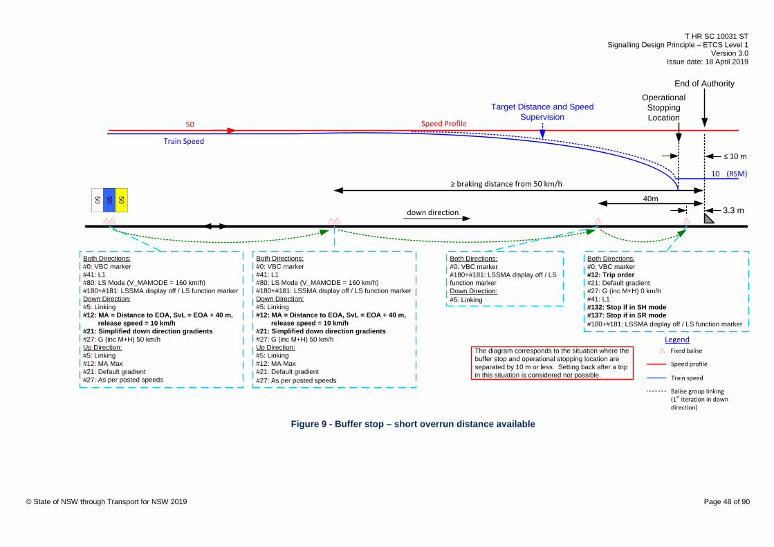
T HR SC 10031 ST Signalling Design Principle – ETCS Level 1
Version 3.0 Issue date: 18 April 2019
50 50 50
Both Directions:#0: VBC marker#41: L1#80: LS Mode (V_MAMODE = 160 km/h)#180+#181: LSSMA display off / LS function markerDown Direction:#5: Linking#12: MA = Distance to EOA, SvL = EOA + 40 m, release speed = 10 km/h#21: Simplified down direction gradients#27: G (inc M+H) 50 km/hUp Direction:#5: Linking#12: MA Max#21: Default gradient#27: As per posted speeds
The diagram corresponds to the situation where the buffer stop and operational stopping location are separated by 10 m or less. Setting back after a trip in this situation is considered not possible.
3.3 m
≥ braking distance from 50 km/h
Both Directions:#0: VBC marker#12: Trip order#21: Default gradient#27: G (inc M+H) 0 km/h#41: L1#132: Stop if in SH mode#137: Stop if in SR mode#180+#181: LSSMA display off / LS function marker
50 Speed Profile
Train Speed
Fixed balise
Legend
Speed profile
Train speed
Target Distance and Speed Supervision
10
Both Directions:#0: VBC marker#41: L1#80: LS Mode (V_MAMODE = 160 km/h)#180+#181: LSSMA display off / LS function markerDown Direction:#5: Linking#12: MA = Distance to EOA, SvL = EOA + 40 m, release speed = 10 km/h#21: Simplified down direction gradients#27: G (inc M+H) 50 km/hUp Direction:#5: Linking#12: MA Max#21: Default gradient#27: As per posted speeds
(RSM)
End of AuthorityOperational
Stopping Location
down direction
≤ 10 m
Balise group linking(1st iteration in down direction)
40m
Both Directions:#0: VBC marker#180+#181: LSSMA display off / LS function markerDown Direction:#5: Linking
© State of NSW through Transport for NSW 2019 Page 48 of 90
Figure 9 - Buffer stop – short overrun distance available

T HR SC 10031 ST Signalling Design Principle – ETCS Level 1
Version 3.0 Issue date: 18 April 2019
7.4.2. Longer overrun distance available Where the distance between the operational stopping location and the buffer stop is greater
than 10 m, the buffer stop balise group (immediately in rear of the EOA) shall consist of two
balises. This allows a train that has overrun to set back without a further brake intervention. The
configuration shall be as follows:
• The EOA shall be 5 m in advance of the operational stopping location.
• A TSM-initiating balise group shall be placed no closer than the braking tool ‘permitted’
distance in rear of the EOA.
• A single balise shall be placed 40 m from the EOA used for calibration purposes.
• A balise group shall be placed with the reference balise at the EOA. For movements
towards the buffer stop, this balise group shall transmit a trip order that immediately
commands the emergency brake. It shall also transmit ‘Danger for shunting information’
and ‘Stop if in SR mode’.
• The release speed depends on the length of the confidence interval at a position just
before reaching the EOA and the distance between the EOA and the buffer stop. Where
this distance is at least 30 m greater than the confidence interval, the release speed shall
be 15 km/h, otherwise it shall be 10 km/h.
For an example of this arrangement, see Figure 10.
© State of NSW through Transport for NSW 2019 Page 49 of 90

T HR SC 10031 ST Signalling Design Principle – ETCS Level 1
Version 3.0 Issue date: 18 April 2019
50 50 50
Both Directions:#0: VBC marker#41: L1#80: LS Mode (V_MAMODE = 160 km/h)#180+#181: LSSMA display off / LS function markerDown Direction:#5: Linking#12: MA = Distance to EOA, SvL = EOA + 40 m, release speed ## = 10 km/h or 15 km/h#21: Simplified down direction gradients#27: G (inc M+H) 50 km/hUp Direction:#5: Linking#12: MA Max#21: Default gradient#27: As per posted speeds
The diagram corresponds to the situation where buffer stop and operational stopping location are separated by more than 10 m.Setting back after a trip in this situation is possible.
≥ braking distance from 50 km/h
Both Directions:#0: VBC marker#41: L1#21: Default gradient#180+#181: LSSMA display off / LS function markerDown Direction:#12: Trip order#27: G (inc M+H) 0 km/h#132: Stop if in SH mode#137: Stop if in SR modeUp Direction:#5: Linking#12: MA Max#27: As per posted speeds#80: LS Mode (V_MAMODE = 160 km/h)
50 Speed Profile
Train Speed
Target Distance and Speed Supervision
Both Directions:#0: VBC marker#41: L1#80: LS Mode (V_MAMODE = 160 km/h)#180+#181: LSSMA display off / LS function markerDown Direction:#5: Linking#12: MA = Distance to EOA, SvL = EOA + 40 m, release speed ## = 10 km/h or 15 km/h#21: Simplified down direction gradients#27: G (inc M+H) 50 km/hUp Direction:#5: Linking#12: MA Max#21: Default gradient#27: As per posted speeds
10 km/h or 15 km/h (RSM)
End of Authority
Operational Stopping Location
>10 m
< 30 m - release speed = 10 km/h≥ 30 m - release speed = 15 km/h
down direction##
5 mconfidence
interval
##
Fixed balise
Legend
Speed profile
Train speed
Balise group linking(1st iteration in down direction)
40m
Both Directions:#0: VBC marker#180+#181: LSSMA display off / LS function markerDown Direction:#5: LinkingUp Direction:#5: Linking
© State of NSW through Transport for NSW 2019 Page 50 of 90
Figure 10 - Buffer stop – long overrun distance available
T HR SC 10031 ST Signalling Design Principle – ETCS Level 1
Version 3.0 Issue date: 18 April 2019
7.5. Yards In the context of this document, a yard refers to any unsignalled line(s) or any line(s) that are
signalled with shunt class routes only. Running lines adjacent to yards shall not be treated as
part of the yard. Only electrified yards need to be considered for ETCS protection.
A yard shall be provided with two balise groups (transmitting duplicated mode profile information
for redundancy), under any of the following circumstances:
• where there is a deemed risk of collision of trains in the yard. This risk shall be deemed to
exist where both of the following conditions are true:
o a particular road or siding exists that fits more than one 8-car train
o entrance to the yard is via a signalled move, not involving ground frame points in the
reverse position
• yards where trains regularly enter service from stabling or maintenance facilities
• yards where trains regularly amalgamate or divide
Yard balise groups are provided to mitigate the following:
• the risk of a train travelling on a running line in SH mode or SR mode, without the
protection provided by LS mode
• operational restrictions by a train’s speed being limited to the 40 km/h SR mode speed limit
until the train passes the next balise group (that transmits an MA for the applicable
direction) on the running line, and a train’s speed being limited to the 25 km/h SH mode
speed limit where the driver fails to complete the procedure that changes the mode to SR
• the risk of a train travelling in a yard faster than the 25 km/h SH mode speed limit
Yard balise groups shall be placed such that they are not passed by a movement wholly within
the yard, as this would cause an emergency brake intervention for this type of movement with a
train in SH mode.
Yard balise groups shall send information applicable to both signalled and unsignalled (wrong
running) train moves.
7.5.1. Yard exit
A 'Stop if in SH mode' order, level transition order and national values shall be transmitted from
the yard balise groups when exiting a yard onto a running line.
The SSP shall be transmitted for trains exiting the yard. The speed profile transmitted shall
include the line speed at the balise group, the turnout speed (high-risk convergence only) and
the safe speed in advance of the turnout. The safe speeds in advance of the turnout shall be the
most restrictive of the line speed and any target speeds applicable.
© State of NSW through Transport for NSW 2019 Page 51 of 90

T HR SC 10031 ST Signalling Design Principle – ETCS Level 1
Version 3.0 Issue date: 18 April 2019
Yard balise groups shall be placed such that any running move is supervised in LS mode as
soon as possible after passing the running signal. See Figure 11.
© State of NSW through Transport for NSW 2019 Page 52 of 90

T HR SC 10031 ST Signalling Design Principle – ETCS Level 1
Version 3.0 Issue date: 18 April 2019
70 70 70
Yard Area
UnlinkedBoth Directions:#3: National Values#12: MA Max#21: Default gradient#41: L1#180+#181: LSSMA display off / LS function markerDown Direction (signalled):#6: VBC removal#27: 1st iteration G (inc M+H) as per turnout speed, 2nd iteration G (inc M+H) 70 km/h#80: LS Mode (V_MAMODE = 160 km/h)#132: Stop if in SH modeUp Direction (signalled):#27: G (inc M+H) as per turnout speed,#80: SH Mode
Down Line
Fixed baliseLegend
Balise group linking(1st iteration)
© State of NSW through Transport for NSW 2019 Page 53 of 90
Figure 11 – Yard exit

T HR SC 10031 ST Signalling Design Principle – ETCS Level 1
Version 3.0 Issue date: 18 April 2019
7.5.2. Yard entry For yard entry, the balise groups shall both transmit an immediate order to change to SH mode.
Yard balise groups should be placed as close as possible in advance of the point where only
shunting or signalled shunt class movements are allowed. See Figure 12 for an example of this
arrangement.
© State of NSW through Transport for NSW 2019 Page 54 of 90

T HR SC 10031 ST Signalling Design Principle – ETCS Level 1
Version 3.0 Issue date: 18 April 2019
Yard Area
70 70 70
Down LineUnlinkedBoth Directions:#3: National Values#12: MA Max#21: Default gradient#41: L1#180+#181: LSSMA display off / LS function markerDown Direction (signalled):#27: G (inc M+H) as per turnout speed#80: SH Mode (immediate)Up Direction (wrong running):#6: VBC Removal#27: G (inc M+H) 160 km/h#80: LS Mode (V_MAMODE: National Value)#132: Stop if in SH mode
Fixed baliseLegend
Balise group linking(1st iteration)
© State of NSW through Transport for NSW 2019 Page 55 of 90
Figure 12 – Yard entry

T HR SC 10031 ST Signalling Design Principle – ETCS Level 1
Version 3.0 Issue date: 18 April 2019
They shall not be placed on running lines, as this would cause trains to change to SH mode
when remaining on a running line.
Where the yard has a specific speed limit lower than 25 km/h, it remains the driver’s
responsibility to avoid exceeding the specified speed limit.
7.6. Turning back When a train terminates and is required to turn back, the driver changes end and starts a new
mission, typically in SR mode. The maximum speed in SR mode is 40 km/h. The next balise
group that is passed (that transmits an MA for the applicable direction) will change the mode to
LS, thus allowing the train to run at line speed.
An additional balise group providing an earlier change to LS mode should be provided where
there is a significant operational benefit in doing so.
7.7. Big metal masses Metal masses on or beneath the track structure can obstruct the ability of the onboard
transmission equipment to function correctly, which in turn can cause alarms on the DMI. These
alarms are suppressed when the metal mass is announced.
A metal mass larger than the dimensions specified in ERTMS/ETCS Subset-036 shall be
classified as a big metal mass. See EGG 1656 Balise Placement and Metal Mass Assessment
Guide for the identification of big metal masses.
Packet #67 contains the big metal mass information. The distance to and length of the big metal
mass shall be transmitted by a big metal mass announcement balise group.
In level 1 territory, big metal masses longer than 10 m shall be announced. In level 0 territory,
big metal masses longer than 300 m shall be announced.
A big metal mass shall be announced on all possible approaches to it.
A big metal mass announcement balise group shall not be placed less than 75 m from the big
metal mass. This distance is based on the network maximum speed of 160 km/h and a
1.5 second onboard delay. Where infrastructure constraints prevent standard placement, the
maximum allowable speed for the section of line may be used in calculating the minimum
distance.
A big metal mass announcement balise group shall not be placed more than 500 m from the big
metal mass. This is to limit the confidence interval either side of the big metal mass.
See Figure 13, Figure 14 and Figure 15 for examples of announcing big metal masses.
© State of NSW through Transport for NSW 2019 Page 56 of 90

T HR SC 10031 ST Signalling Design Principle – ETCS Level 1
Version 3.0 Issue date: 18 April 2019
Both Directions:#0: VBC marker#12: MA Max#21: Default gradient#41: L1#180+#181: LSSMA display off / LS function markerUp Direction:#27: 160 km/h#67: Big Metal Masses#80: LS Mode (V_MAMODE: National Value)Down Direction:#5: Linking#27: As per posted speeds#80: LS Mode (V_MAMODE = 160 km/h)
BMM
For Wrong Running
Both Directions:#0: VBC marker#12: MA Max#21: Default gradient#41: L1#180+#181: LSSMA display off / LS function markerDown Direction:#5: Linking#27: As per posted speeds#67: Big Metal Masses#80: LS Mode (V_MAMODE = 160 km/h)Up Direction:#27: 160 km/h#80: LS Mode (V_MAMODE: National Value)
75 m to 500 m
Down Line
75 m to 500 m
Fixed baliseLegend
Balise group linking(1st iteration)
© State of NSW through Transport for NSW 2019 Page 57 of 90
Figure 13 - Big metal masses – unidirectional line
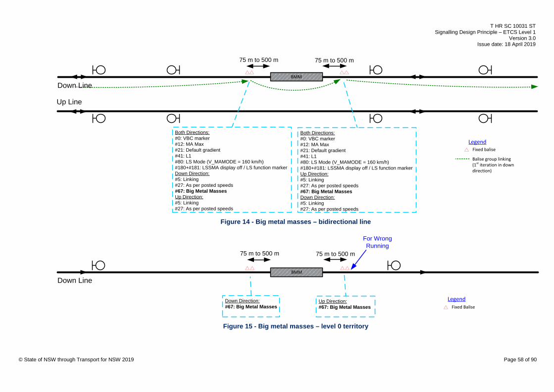
T HR SC 10031 ST Signalling Design Principle – ETCS Level 1
Version 3.0 Issue date: 18 April 2019
BMM
Both Directions:#0: VBC marker#12: MA Max#21: Default gradient#41: L1#80: LS Mode (V_MAMODE = 160 km/h)#180+#181: LSSMA display off / LS function markerUp Direction:#5: Linking#27: As per posted speeds#67: Big Metal MassesDown Direction:#5: Linking#27: As per posted speeds
Both Directions:#0: VBC marker#12: MA Max#21: Default gradient#41: L1#80: LS Mode (V_MAMODE = 160 km/h)#180+#181: LSSMA display off / LS function markerDown Direction:#5: Linking#27: As per posted speeds#67: Big Metal MassesUp Direction:#5: Linking#27: As per posted speeds
Down Line
Up Line
Fixed baliseLegend
75 m to 500 m 75 m to 500 m
Balise group linking(1st iteration in down direction)
Figure 14 - Big metal masses – bidirectional line
Up Direction:#67: Big Metal Masses Fixed Balise
Legend
BMM
Down Direction:#67: Big Metal Masses
For Wrong Running
75 m to 500 m 75 m to 500 m
Down Line
© State of NSW through Transport for NSW 2019 Page 58 of 90
Figure 15 - Big metal masses – level 0 territory
T HR SC 10031 ST Signalling Design Principle – ETCS Level 1
Version 3.0 Issue date: 18 April 2019
Balise groups shall not be placed in a big metal mass area or within the confidence interval
either side of it.
Where the separation of two or more big metal masses is small enough to prevent individual
announcement due to confidence interval constraints, then the big metal mass announcement
balise group shall announce all the big metal masses.
A big metal mass announcement shall not be transmitted to a train that diverges away from a
big metal mass, unless it avoids the use of an LEU and there are no balises on the diverging
line within the bounds of the resulting confidence interval.
7.8. Wrong running Wrong running refers to train movements on running lines in the unsignalled direction. All wrong
running movements shall be supervised to a maximum speed of 40 km/h, in accordance with
RailSafe NSY 514 Special Proceed Authority. In general, the speed supervision of wrong
running movements (including all balise groups in the wrong running section) shall utilise
packet #80 (mode profile). The speed is configured (with the use of the V_MAMODE variable)
to use the national value V_NVLIMSUPERV of 40 km/h, rather than limiting the speed through
packet #27 SSP set to match the network speed of 160 km/h. This approach allows a possible
future alteration to the maximum special proceed authority (SPA) speed while minimising the
number of balises requiring a data alteration.
Exceptions to using the mode profile to supervise the wrong running speed are as follows:
• The balise group contains repositioning information. In such case, the SSP shall be used to
enforce the wrong running speed and no mode profile shall be sent.
• The first balise group at the exit from the wrong running movement (that is, the first balise
group in the signalled movement) contains repositioning information. In such a case, the
last balise group in the wrong running section shall use SSP to enforce the wrong running
speed and the mode profile shall be configured to use the maximum network speed of
160 km/h.
7.8.1. Wrong running entry In order for the train to be updated with the appropriate speed supervision for a wrong running
movement, a wrong running entry point shall be defined to permit the onboard equipment to be
updated as early as possible to avoid a train maintaining line speed.
Where no crossovers or turnouts are provided, the wrong running entry point shall be assumed
to be at the point where there is no signalled move in the applicable direction over that portion
of track.
Where crossovers or turnouts are provided, the wrong running entry point is typically defined as
the toe of the trailing points. © State of NSW through Transport for NSW 2019 Page 59 of 90

T HR SC 10031 ST Signalling Design Principle – ETCS Level 1
Version 3.0 Issue date: 18 April 2019
A wrong running entry balise group shall be placed at a nominal 10 m in advance of the wrong
running entry point; however, a distance of up to 160 m is permitted (based on typical 8-car
EMU).The wrong running entry function is permitted to be in a balise group in rear of the wrong
running entry point to allow the function to be combined in a balise group performing another
function, provided there is no additional operational restriction or safety risk, see Figure 16.
© State of NSW through Transport for NSW 2019 Page 60 of 90
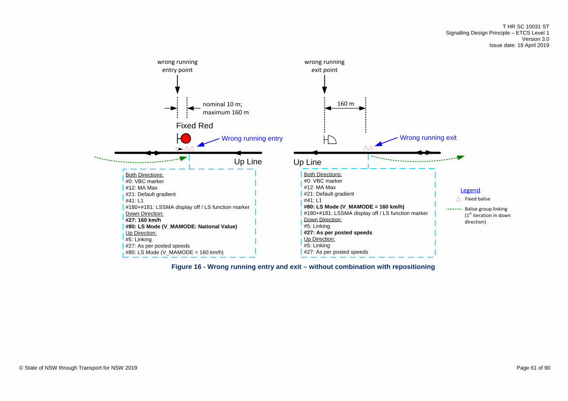
T HR SC 10031 ST Signalling Design Principle – ETCS Level 1
Version 3.0 Issue date: 18 April 2019
Both Directions:#0: VBC marker#12: MA Max#21: Default gradient#41: L1#80: LS Mode (V_MAMODE = 160 km/h)#180+#181: LSSMA display off / LS function markerDown Direction:#5: Linking#27: As per posted speedsUp Direction:#5: Linking #27: As per posted speeds
Fixed baliseLegend
Up Line
Fixed Red
Both Directions:#0: VBC marker#12: MA Max#21: Default gradient#41: L1#180+#181: LSSMA display off / LS function markerDown Direction:#27: 160 km/h#80: LS Mode (V_MAMODE: National Value)Up Direction:#5: Linking #27: As per posted speeds#80: LS Mode (V_MAMODE = 160 km/h)
Up Line
Wrong running entry Wrong running exit
nominal 10 m;maximum 160 m
wrong runningentry point
160 m
wrong runningexit point
Balise group linking(1st iteration in down direction)
© State of NSW through Transport for NSW 2019 Page 61 of 90
Figure 16 - Wrong running entry and exit – without combination with repositioning
T HR SC 10031 ST Signalling Design Principle – ETCS Level 1
Version 3.0 Issue date: 18 April 2019
Two situations exist for a wrong running entry balise group, depending on whether the balise
group also transmits packet #16 in the applicable direction as a repositioning balise group.
Where the balise group does not transmit packet #16, the balise group shall transmit
packet #80, indicating through the V_MAMODE variable that speed is monitored to the national
value. Packet #27 shall transmit the network maximum speed of 160 km/h, see Figure 16.
Where the balise group transmits packet #16, it cannot also transmit packet #80. The balise
group shall utilise packet #27 to transmit a speed of 40 km/h. The next balise group in advance
shall transmit packet #80, indicating through the V_MAMODE variable that speed is monitored
to the national value. Packet #27 at this next balise group shall transmit the network maximum
speed of 160 km/h, see Figure 17.
© State of NSW through Transport for NSW 2019 Page 62 of 90
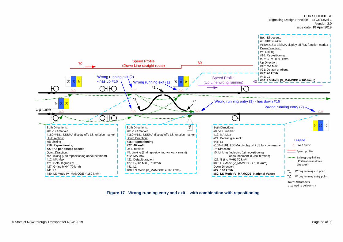
T HR SC 10031 ST Signalling Design Principle – ETCS Level 1
Version 3.0 Issue date: 18 April 2019
70 70 7070 70 70
707070Both Directions:#0: VBC marker#180+#181: LSSMA display off / LS function markerUp Direction:#5: Linking#16: Repositioning#27: As per posted speedsDown Direction:#5: Linking (2nd repositioning announcement)#12: MA Max#21: Default gradient#27: G (inc M+H) 70 km/h#41: L1#80: LS Mode (V_MAMODE = 160 km/h)
70Speed Profile
(Down Line straight route)
Fixed baliseLegend
Both Directions:#0: VBC marker#180+#181: LSSMA display off / LS function markerDown Direction:#16: Repositioning#27: 40 km/hUp Direction:#5: Linking (2nd repositioning announcement)#12: MA Max#21: Default gradient#27: G (inc M+H) 70 km/h#41: L1#80: LS Mode (V_MAMODE = 160 km/h)
Speed Profile(Up Line wrong running) 40
Both Directions:#0: VBC marker#12: MA Max#21: Default gradient#41: L1#180+#181: LSSMA display off / LS function markerUp Direction:#5: Linking (including 1st repositioning
announcement in 2nd iteration)#27: G (inc M+H) 70 km/h#80: LS Mode (V_MAMODE = 160 km/h)Down Direction:#27: 160 km/h#80: LS Mode (V_MAMODE: National Value)
80 80 80
80
X60
Both Directions:#0: VBC marker#180+#181: LSSMA display off / LS function markerDown Direction:#5: Linking#16: Repositioning #27: G+M+H 80 km/hUp Direction:#12: MA Max#21: Default gradient#27: 40 km/h#41: L1#80: LS Mode (V_MAMODE = 160 km/h)
Up Line
Speed profile
Wrong running entry (1) - has down #16Wrong running entry (2)
Wrong running exit (2)- has up #16 Wrong running exit (1)
Note: All turnouts assumed to be low-risk
*1
*1
*2
Balise group linking(1st iteration in down direction)
*1*2
Wrong running exit point
Wrong running entry point
© State of NSW through Transport for NSW 2019 Page 63 of 90
Figure 17 - Wrong running entry and exit – with combination with repositioning

T HR SC 10031 ST Signalling Design Principle – ETCS Level 1
Version 3.0 Issue date: 18 April 2019
An ETCS trainstop balise group cannot be combined with a wrong running entry function in the
same direction, as the trip order issued by the ETCS trainstop changes the onboard mode to
trip mode. When trip mode is entered, certain information that is stored onboard is deleted.
Refer to ERTMS/ETCS Subset-026-4 for more details. A preferred separation of 100 m, up to a
maximum of 160 m, shall be provided between an ETCS trainstop balise group and a wrong
running entry balise group to allow a tripped train to come to a stand. See Figure 20 which
shows a wrong running entry balise group in advance of a fixed red signal fitted with an ETCS
trainstop balise group.
7.8.2. Wrong running exit In order for the train to be updated with the appropriate speed supervision for the signalled
direction, a wrong running exit point shall be defined to permit the onboard equipment to be
updated as early as possible to avoid the train's speed being restricted by the wrong running
speed supervision.
The wrong running exit point is typically defined as the point where there is a signalled move in
the applicable direction over the portion of track.
Where the wrong running move is through a crossover or turnout, the wrong running exit point is
typically defined as the toe of the trailing points.
A wrong running exit balise group shall be placed at 160 m (based on typical 8-car EMU) in
advance of the wrong running exit point.
Exceptions to the 160 m placement requirement are as follows:
• A distance less than 160 m is permitted to allow the wrong running exit function to be
combined in a balise group performing another function.
• A distance greater than 160 m is permitted to avoid unintentionally revoking TSM. See
Section 10.2 for details.
• A distance greater than 160 m is permitted to minimise the potential operational impact or
unnecessary mode change commands.
Two situations exist for a wrong running exit balise group, depending on whether the balise
group also transmits packet #16 in the applicable direction as a repositioning balise group.
Where the balise group does not transmit packet #16, the balise group shall transmit
packet #80, reverting the V_MAMODE variable back to the network maximum speed of
160 km/h. Packet #27 shall transmit the line speed. See Figure 16.
Where the balise group transmits packet #16, it cannot also transmit packet #80. Packet #27
shall transmit the line speed. The balise group first in rear shall transmit packet #80, reverting
the V_MAMODE variable back to the network maximum speed of 160 km/h. This balise group in
rear shall utilise packet #27 to transmit a speed of 40 km/h. See Figure 17.
© State of NSW through Transport for NSW 2019 Page 64 of 90

T HR SC 10031 ST Signalling Design Principle – ETCS Level 1
Version 3.0 Issue date: 18 April 2019
7.8.3. Wrong running level crossings
Speed supervision in the unsignalled direction shall apply to protected level crossings and
protected pedestrian level crossings that have no active protection for movements in the
unsignalled direction.
An ETCS TSR shall be used for this protection. Packet #65 contains the TSR. A target speed of
15 km/h shall apply at a target point of 50 m in rear of the level crossing approach edge. The
length of the TSR shall be 1 m.
The TSR shall be transmitted from two consecutive balise groups. The first transmission is for
redundancy purposes, transmitted from a balise group at a minimum distance of 300 m from the
level crossing approach edge. The second balise group shall be at least the permitted distance
from the TSR target point. See Figure 18. The permitted distance shall be obtained from the
braking tool, using 40 km/h as the initial speed.
© State of NSW through Transport for NSW 2019 Page 65 of 90

T HR SC 10031 ST Signalling Design Principle – ETCS Level 1
Version 3.0 Issue date: 18 April 2019
Both Directions:#0: VBC marker#12: MA Max#21: Simplified up direction gradients#41: L1#180+#181: LSSMA display off / LS function markerUp Direction:#5: Linking (one iteration)#27: 160 km/h#65: Distance to level crossing minus 50 m, 15 km/h TSR for 1 m#72: Text message: ‘Warning: level crossing’ (appears 300 m before hazard)#80: LS Mode (V_MAMODE: National Value)Down Direction:#5: Linking#27: As per posted speeds#80: LS Mode (V_MAMODE = 160 km/h)
40Speed Profile
(Down Line wrong running)
Train speed
50 m
15
TSR
Fixed baliseLegend
Speed profile
Train speed
Balise group linking(1st iteration in unsignalled direction)
Both Directions:#0: VBC marker#12: MA Max#21: Simplified up direction gradients#41: L1#180+#181: LSSMA display off / LS function markerUp Direction:#27: 160 km/h#65: Distance to level crossing minus 50 m, 15 km/h TSR for 1 m#80: LS Mode (V_MAMODE: National Value)Down Direction:#5: Linking#27: As per posted speeds#80: LS Mode (V_MAMODE = 160 km/h)
Down Line
Up Line
XC XH
XCXH≥ braking distance
(40 km/h to 15 km/h)
≥ 300 m
© State of NSW through Transport for NSW 2019 Page 66 of 90
Figure 18 - Wrong running level crossing

T HR SC 10031 ST Signalling Design Principle – ETCS Level 1
Version 3.0 Issue date: 18 April 2019
The redundant balise group shall transmit an important, plain text message to be displayed to
the driver. Packet #72 contains the text for the message. Driver acknowledgement shall not be
requested. The message shall be ‘Warning: level crossing’. The message shall be displayed
from 300 m until 49 m in rear of the level crossing approach edge.
8. Controlled balise group functions A controlled balise group is a balise group that can vary the message that it transmits
depending on the state of the signalling controls. Controlled balise groups shall be provided for
ETCS trainstops, high-risk turnouts and high-risk overruns. Controlled balise groups are
required for approach balise groups.
A controlled balise group typically consists of one controlled balise and one fixed balise. The
fixed balise always transmits the same telegram, whereas the controlled balise transmits a
telegram selected by a connected LEU.
ERA documents also use the term ‘switchable balise’ for a controlled balise.
8.1. Lineside electronic units An LEU receives vital inputs from the conventional signalling system and sends outputs to one
or more controlled balises.
The Alstom Micro-coder type 1 module is the only LEU with type approval.
Note: This document is currently written to support the Alstom Micro-coder type 1 module;
however this document will be updated to support other type approved LEUs.
An LEU shall not control balises on more than one line. An LEU shall not interface to both Up
and Down signals.
8.1.1. Lineside electronic unit naming Each LEU shall be assigned a unique name, complying with the following naming structure:
WWWXXXXXXXX LEU A
Note: The spaces separate certain parts.
Underscores shall replace spaces in filenames.
WWW
WWW shall be the three-letter location code as listed in T MU AM 01007 TI Asset Reference
Codes Register.
It shall be the location code of the nearest station to the interfaced signal.
The station kilometrages in TS TOC 3 shall be used in determining the nearest station.
© State of NSW through Transport for NSW 2019 Page 67 of 90

T HR SC 10031 ST Signalling Design Principle – ETCS Level 1
Version 3.0 Issue date: 18 April 2019
The location code shall be omitted from the name of LEU sub-assets, such as terminals, power
supply units and Ethernet switches.
XXXXXXXX
XXXXXXXX is a maximum of eight characters that describe the signal name of the interfaced
signal.
XXXXXXXX shall be in accordance with the signal identification plate; however, it shall not
include spaces, decimal points or any suffix denoting line name.
LEU
The text ‘LEU’ shall form part of the LEU name.
Naming suffix
Each LEU name shall have a sequential alphabetical suffix, with the first or only LEU using ‘A’.
Subsequent locally networked LEUs shall use ‘B’ and ‘C’.
The following are examples of LEU names established using this convention:
• CWDCD29 LEU A
• CWDCD29 LEU B
• WRE643 LEU A
• CTND342 LEU A
• ARNSM810 LEU A
8.1.2. Signalling inputs Two forms of input arrangement are possible – relay contact sensing and lamp current sensing.
When the Alstom Micro-coder type 1 module is used as the LEU, contact sensing is achieved
using current sensing inputs with a series load resistor.
Contact sensing shall be used where signals are operated by relays. Current sensing shall be
used where signals are not operated by relays, that is, where computer-based interlocking (CBI)
equipment directly drives the signal lamps. The exception is that turnout repeaters operated by
relays shall use current sensing where CBI equipment directly drives the running aspect signal
lamps, such that standard LEU data can be utilised. Contact sensing shall be used for route
indicators, when required, where they are operated by relays.
In a contact sensing arrangement, inputs shall disregard the lamp proving status.
A vital relay interface to facilitate contact sensing shall be provided where controls of
mechanically operated signals are required as LEU inputs.
© State of NSW through Transport for NSW 2019 Page 68 of 90

T HR SC 10031 ST Signalling Design Principle – ETCS Level 1
Version 3.0 Issue date: 18 April 2019
A bypass terminal shall be provided for each current sensing input to retain the displayed
aspect of a signal when it is necessary to disconnect the LEU.
Alstom Micro-coder type 1 modules have a maximum of six physical inputs (from the signalling
system) and a maximum of two physical outputs (to controlled balises). These LEUs may be
networked to accommodate a higher number of inputs or outputs. The balise message selection
table can consider a maximum of 16 inputs. The controlled balise(s) should be connected to the
first LEU.
The standard input allocation shown in T HR SC 00003 ST applies to the Alstom Micro-coder
type 1 module and allows standard LEU data to be utilised. Spare inputs of an LEU shall be
used if it avoids the provision of an additional LEU.
8.1.3. Location of LEUs LEUs shall be installed in the signal control output location.
A cabinet compliant to SPG 0708 Small Buildings and Location Cases shall be provided.
Single cutting of contacts may be provided where an annexe cabinet is used.
8.1.4. Default telegrams If a controlled balise loses communication with the LEU, for example due to an LEU failure, then
the balise transmits its default telegram. If the inputs of an LEU are not a valid combination, for
example, due to a relay failure, then the LEU selects its default telegram. The default telegram
header shall allocate a message counter value of 254 to the M_MCOUNT variable. This value
deems the message inconsistent for both directions, triggering a linking reaction. The failure is
reported to the driver by a system text message displayed on the DMI.
Additional important, plain text messages shall also be sent to the train to be logged in the
juridical recording unit (JRU); however, these messages are not reported to the driver. The text
messages shall be valid for both directions. The message shall be 'DEF_BAL' for the default
balise telegram and 'DEF_LEU' for the default LEU telegram. The messages shall start
immediately, shall not require driver acknowledgement and shall have no ending conditions.
Controlled balises shall always transmit packet #254 under a failure situation, indicating that the
telegram can contain default information. It shall be valid for both directions.
8.1.5. Power arrangements
The power for the LEU shall be derived from the same power source as the signalling system.
Each LEU shall have its own power supply unit. A power supply unit can additionally supply
power to an Ethernet switch where the LEU has no outputs to balises. Each power supply unit
shall be separately fused.
© State of NSW through Transport for NSW 2019 Page 69 of 90
T HR SC 10031 ST Signalling Design Principle – ETCS Level 1
Version 3.0 Issue date: 18 April 2019
Where contact sensing is used, multiple lines shall not be affected by the failure of a single
transformer supplying power to LEU inputs. A separate transformer should be provided for the
signal controls and LEU interface per signal. Where site constraints exist, a single transformer
shall be provided for the interface of more than one signal up to a maximum of three LEU
modules.
A fuse shall be provided for each signal for the inputs in a contact sensing arrangement. The
fuse shall be located in the same location enclosure as the LEU.
Surge protection shall be provided at the 120 V ac bus supplying the LEU equipment if no inbuilt
surge protection is provided on this bus.
8.2. ETCS trainstops An ETCS trainstop is an alternative to the trip arm style trainstop.
Where an ETCS trainstop balise group is provided for a signal that is required to provide ‘no trip’
for one or more aspects, it shall consist of one controlled balise and one fixed balise. See
Figure 19.
© State of NSW through Transport for NSW 2019 Page 70 of 90

T HR SC 10031 ST Signalling Design Principle – ETCS Level 1
Version 3.0 Issue date: 18 April 2019
90 80 70
Both Directions:#0: VBC marker#12: MA Max#21: Default gradient#41: L1#180+#181: LSSMA display off / LS function markerDown Direction:#5: Linking; Service brake linking reaction#27: G 70 km/h + M 80 km/h + H 90 km/h#80: LS Mode (V_MAMODE = 160 km/h)Up Direction:#27: 160 km/h#80: LS Mode (V_MAMODE: National Value)
Transmitted regardless of aspectBoth Directions:#0: VBC marker#21: Default gradient#41: L1#180+#181: LSSMA display off / LS function markerDown Direction:#27: G 70 km/h + M 80 km/h + H 90 km/hUp Direction:#12: MA Max#27: 160 km/h#80: LS Mode (V_MAMODE: National Value)Running aspect at stopDown Direction:#12: Trip order#132: Stop if in SH mode#137: Stop if in SR modeProceed running aspectDown Direction:#5: Linking; Service brake linking reaction#12: MA Max#80: LS Mode (V_MAMODE = 160 km/h)
Controlled balise
Fixed balise
Legend
Down Line
Balise group linking(1st iteration)
© State of NSW through Transport for NSW 2019 Page 71 of 90
Figure 19 - ETCS trainstop
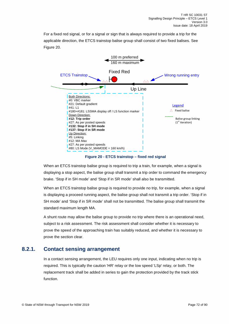
T HR SC 10031 ST Signalling Design Principle – ETCS Level 1
Version 3.0 Issue date: 18 April 2019
For a fixed red signal, or for a signal or sign that is always required to provide a trip for the
applicable direction, the ETCS trainstop balise group shall consist of two fixed balises. See
Figure 20.
Fixed balise
Legend
Balise group linking(1st iteration)
Fixed Red
Both Directions:#0: VBC marker#21: Default gradient#41: L1#180+#181: LSSMA display off / LS function markerDown Direction:#12: Trip order#27: As per posted speeds#132: Stop if in SH mode#137: Stop if in SR modeUp Direction:#5: Linking #12: MA Max#27: As per posted speeds#80: LS Mode (V_MAMODE = 160 km/h)
Up Line
Wrong running entryETCS Trainstop
100 m preferred160 m maximum
© State of NSW through Transport for NSW 2019 Page 72 of 90
Figure 20 - ETCS trainstop – fixed red signal
When an ETCS trainstop balise group is required to trip a train, for example, when a signal is
displaying a stop aspect, the balise group shall transmit a trip order to command the emergency
brake. ‘Stop if in SH mode’ and ‘Stop if in SR mode’ shall also be transmitted.
When an ETCS trainstop balise group is required to provide no trip, for example, when a signal
is displaying a proceed running aspect, the balise group shall not transmit a trip order. ‘Stop if in
SH mode’ and ‘Stop if in SR mode’ shall not be transmitted. The balise group shall transmit the
standard maximum length MA.
A shunt route may allow the balise group to provide no trip where there is an operational need,
subject to a risk assessment. The risk assessment shall consider whether it is necessary to
prove the speed of the approaching train has suitably reduced, and whether it is necessary to
prove the section clear.
8.2.1. Contact sensing arrangement In a contact sensing arrangement, the LEU requires only one input, indicating when no trip is
required. This is typically the caution 'HR' relay or the low speed 'LSp' relay, or both. The
replacement track shall be added in series to gain the protection provided by the track stick
function.

T HR SC 10031 ST Signalling Design Principle – ETCS Level 1
Version 3.0 Issue date: 18 April 2019
8.2.2. Current sensing arrangement
In a current sensing arrangement, the LEU requires inputs from the following lamps:
• running aspects, including low speed aspects
• marker lights
• close-up aspects
The LEU does not require inputs from the following lamps:
• co-acting signals
• turnout repeaters
• route indicators
• other subsidiary aspects
In the event of lamp failure, the ETCS trainstop shall transmit a message to reflect the degraded
state of the signalling system consistent with the most restrictive combination of the remaining
illuminated lamps.
In the event of an invalid signal indication, the LEU inputs shall be deemed an invalid
combination, resulting in the LEU selecting its default telegram, triggering the linking reaction
and commanding the service brake.
8.3. High-risk turnouts A balise group using TSM shall be provided on approach to a turnout that is deemed high-risk.
This minimises the risk of a derailment resulting from excessive speed.
Refer to PR S 45012 Identification of High Risk Turnouts for supporting information and
guidance.
8.3.1. Turnout assessment A risk-based approach shall be followed in determining high-risk turnouts.
The following factors should be considered in this determination:
• line speed or speeds on approach
• signalling controls on approach
• attainable speed, considering factors such as signalling controls
• likeliness of acceleration after receiving a restrictive aspect
• turnout design speed
• any overspeed allowance afforded by the turnout geometry
© State of NSW through Transport for NSW 2019 Page 73 of 90

T HR SC 10031 ST Signalling Design Principle – ETCS Level 1
Version 3.0 Issue date: 18 April 2019
• frequency of timetabled train movements
• for the turnout protecting signal, the likeliness of an overrun past the signal at stop, taking
cognisance of the distance from the signal to the turnout
• consequences of a derailment, including:
o injury and loss of life to passengers, staff and the public
o damage to infrastructure and rolling stock
o disruption to train operations
o public relations
• likeliness and consequences of an overrun or misrouting into an unwired section of track
• risks associated with monitoring the speed of the plain line track in advance of the turnout
using simple ceiling speed monitoring
Where any of the above factors change for a given turnout, a new risk assessment shall be
required to reassess the risk classification of the turnout.
8.3.2. High-risk turnout balise group A high-risk turnout balise group shall consist of one controlled balise and one fixed balise. The
preferred position of the balise group is at the ‘permitted distance’ obtained from the braking
tool, using the turnout as the target point and the published turnout speed as the target speed.
The balise group may be positioned farther than the ‘permitted distance’, including at an outer
signal that is one or more blocks in rear of the home signal of the turnout. See Figure 21.
© State of NSW through Transport for NSW 2019 Page 74 of 90

T HR SC 10031 ST Signalling Design Principle – ETCS Level 1
Version 3.0 Issue date: 18 April 2019
100
90 80
Transmitted regardless of aspectBoth Directions:#0: VBC marker#21: Simplified down direction gradients#12: MA Max#41: L1#181: LS function markerDown Direction:#5: Linking (including 1st repositioning announcement in 2nd iteration)#27: 1st (or only) iteration – G 80 km/h + M 90 km/h + H 100 km/h#80: LS Mode (V_MAMODE = 160 km/h)Up Direction:#27: 160 km/h#80: LS Mode (V_MAMODE: National Value)#180: LSSMA display offDiverging route clear / Home signal at stopDown Direction:#27: 2nd iteration – G (inc M+H) 60km/h, 3rd iteration – speeds for diverging line*#180: LSSMA display onStraight route clearDown Direction:#180: LSSMA display off
≥ braking distance(line speed to turnout Speed)
90
60
Medium Speed Profile (turnout route)
Train Speed
X60
Controlled balise
Fixed balise
Legend
Medium speed profile
Train speed
Balise group linking(1st iteration in down direction)
Onboard supervised speed
Both Directions:#0: VBC marker#12: MA Max#21: Simplified down direction gradients#41: L1#180+#181: LSSMA display off / LS function markerDown Direction:#5: Linking #27: 1st iteration – G 80 km/h + M 90 km/h + H 100 km/h, 2nd iteration – G (inc M+H) 60 km/h#80: LS Mode (V_MAMODE = 160 km/h)Up Direction:#27: 160 km/h#80: LS Mode (V_MAMODE: National Value)
NOTES:
* When the home signal for the turnout is at stop, no speeds shall be transmitted for the diverging line.
** This wrong running entry balise group shall not transmit packets #27 or #180 for the down direction.
707070
**Down Line
Up Line
© State of NSW through Transport for NSW 2019 Page 75 of 90
Figure 21 - High-risk turnout

T HR SC 10031 ST Signalling Design Principle – ETCS Level 1
Version 3.0 Issue date: 18 April 2019
When determining the position of the balise group, the following factors shall be taken into
account:
• braking distance
• cable trenching costs
• the need for look-ahead
• the need for additional LEUs
• the need for approach balise groups
The balise group shall transmit an SSP for the straight route with the home signal of the turnout
clear for the straight main class route and all other intermediate signals clear between the balise
group and the home signal. This SSP revokes the redundant target speed information sent from
the balise group in rear.
The balise group shall transmit an SSP for the turnout route with the home signal of the turnout
clear for the main class turnout route and all intermediate signals clear. The SSP shall include
iterations for the turnout speed and the line speed of the diverging line, starting at the toe of the
trailing points or the first insulated rail joint in advance of the clearance point. Train length delay
shall not be enforced.
Where neither of these conditions is satisfied, for example, when the home signal of the turnout
is at stop, the balise group shall transmit an SSP that is consistent with the most restrictive
turnout route; however, it shall not transmit an iteration for the line speed of any diverging line.
Where the home signal protects multiple turnouts, the distance between the TSM initiating
balise group and each high-risk turnout should be considered in determining the most restrictive
speed profile. In some situations, the speed profile may include more than one turnout speed.
Where the home signal also protects low-risk turnouts, they should not be considered for the
purpose of calculating the most restrictive speed profile.
The LEU controlling the controlled balise typically interfaces with an outer signal. There are
situations where it interfaces with the home signal of the turnout, either due to a relatively short
braking distance, or where an additional balise group is required for approach purposes. See
Section 8.5 for the requirements of approach balise groups.
There shall be sufficient inputs to the LEU to positively identify each main class route (requiring
a different TSM response) cleared at the home signal of the turnout, regardless of which signal
the LEU is interfaced to. Multiple routes may be combined in one LEU input, where each
combined route has the same TSM response regarding turnout speeds, associated target points
and line speeds of the diverging line in advance of the turnouts. Further combination of inputs is
possible where the line speeds of the diverging lines do not need to be identified at the TSM
initiating balise group due to these speeds being transmitted from an approach balise group.
© State of NSW through Transport for NSW 2019 Page 76 of 90

T HR SC 10031 ST Signalling Design Principle – ETCS Level 1
Version 3.0 Issue date: 18 April 2019
See Section 8.5 for details. Where the required input functions are not available in the same
location as the LEU, look ahead is required. See Section 8.6 for details.
Refer to T HR SC 00003 ST for examples of inputs to LEUs.
Where a shunt route is clear at the home signal of a turnout, the TSM shall be revoked or
relaxed if both of the following conditions are true:
• the LEU interfaces with the home signal of the turnout
• there is an identified operational restriction in applying the most restrictive TSM
The TSM shall be revoked or relaxed by applying the SSP applicable to the main class route of
the same destination.
8.3.3. Contact sensing arrangement In a contact sensing arrangement, each LEU input shall apply to one route from the home signal
of the turnout, unless routes can be combined. The input shall consist of the control relays for
the first or higher proceed aspect clear for the applicable main class route and all intermediate
signals clear. Multiple routes from the home signal shall be combined into one input where the
routes have the same TSM response regarding turnout speeds, target points and line speeds of
the diverging line in advance of the turnouts.
Input 1 of the LEU shall be allocated to the straight route at the turnout. TSM shall be revoked
when this input is made. Additional controls shall be added to this input if TSM is required to be
revoked for other reasons, such as where there would be an operational impact in applying
TSM to a train that will be routed away before reaching the turnout.
Input 2 of the LEU shall be allocated to the turnout route, or to the least restrictive turnout route
where there are multiple high-risk turnouts from the same signal.
Further inputs shall be allocated in increasing restriction order where there are multiple high-risk
turnouts from the same signal.
The replacement track shall be added in series to all inputs to gain the protection provided by
the track stick function. The exception to this is where a shunt route revokes or relaxes TSM,
and it is possible for the route to clear with the replacement track occupied. In this situation, the
shunt control portion of the input shall bypass the replacement track.
8.3.4. Current sensing arrangement In the event of lamp failure in a current sensing arrangement, the balise group shall transmit a
message consistent with the most restrictive combination of the remaining illuminated lamps.
In the event of an invalid signal indication, the LEU inputs shall be deemed an invalid
combination, resulting in the LEU selecting its default telegram. Speed will be supervised to the
profile transmitted by the redundant TSM balise group.
© State of NSW through Transport for NSW 2019 Page 77 of 90

T HR SC 10031 ST Signalling Design Principle – ETCS Level 1
Version 3.0 Issue date: 18 April 2019
Outer signals
Where the LEU interfaces to an outer signal, the LEU requires inputs from the following lamps:
• running aspects in the main heads
• marker lights
• turnout repeaters (preferably using current sensing, even if relay-driven, where the running
aspects use current sensing)
• bands of lights and any necessary main line route indicators in the following situations:
o the route leads to the home signal of the turnout
o there is a requirement to revoke TSM for a train routed away before reaching the
turnout
The LEU does not require inputs from the following lamps:
• low-speed aspect
• close-up aspects
• co-acting signals
• miniature route indicators
• shunt aspects
• other subsidiary aspects
Home signals
Where the LEU interfaces to the home signal of the turnout, the LEU requires inputs from the
following lamps:
• yellow and green aspects of single light signals
• marker lights
• all aspects in the top head of double light signals
• lower green aspect of double light signals
• low-speed aspects
• close-up aspects
• bands of lights
• main line route indicators (using contact sensing if relay-driven)
• shunt aspects and any applicable route indicators necessary to positively identify any shunt
routes that revoke or relax TSM
© State of NSW through Transport for NSW 2019 Page 78 of 90
T HR SC 10031 ST Signalling Design Principle – ETCS Level 1
Version 3.0 Issue date: 18 April 2019
The LEU does not require inputs from the following lamps:
• red aspects of single light signals
• red and yellow aspects in the lower head of double light signals
• co-acting signals
• turnout repeaters
• other subsidiary aspects
8.4. High-risk overruns The determination of whether an overrun past a signal at stop is deemed high-risk is outside the
scope of this standard.
Where an overrun is deemed high-risk, it is due to one or more of the three types of identified
hazards, namely deficient overlaps, high-risk catchpoints and high-risk level crossings. The
signal that is overrun is termed the ‘protecting’ signal.
In determining a high-risk overrun, the trip speed would generally have been assumed to be the
line speed on approach to the first warning signal. Where there is a decrease in line speed
between the first warning signal and the protecting signal, it may be possible to sufficiently
mitigate the hazard from the high-risk overrun by treating the speed sign as high-risk. See
Section 7.2.1. Where this solution is not possible, a balise group using TSM shall be provided
on approach to the protecting signal.
8.4.1. High-risk overrun balise group A high-risk overrun balise group shall consist of one controlled balise and one fixed balise. The
preferred position of the balise group is at the ‘permitted distance’ obtained from the braking
tool, using the protecting signal as the target point. See Figure 22.
© State of NSW through Transport for NSW 2019 Page 79 of 90
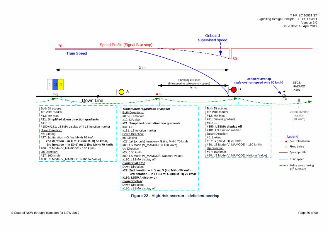
T HR SC 10031 ST Signalling Design Principle – ETCS Level 1
Version 3.0 Issue date: 18 April 2019
70 70 70
Controlled balise
Fixed balise
Legend
Speed profile
Train speed
ETCSHAZARDPOINT
Correct overlap position
(70 km/h)
70 Speed Profile (Signal B at stop)
Train Speed
Transmitted regardless of aspectBoth Directions:#0: VBC marker#12: MA Max#21: Simplified down direction gradients#41: L1#181: LS function markerDown Direction:#5: Linking#27: 1st (or only) iteration – G (inc M+H) 70 km/h#80: LS Mode (V_MAMODE = 160 km/h)Up Direction#27: 160 km/h#80: LS Mode (V_MAMODE: National Value)#180: LSSMA display offSignal B at stopDown Direction:#27: 2nd iteration – in Y m: G (inc M+H) 50 km/h, 3rd iteration – in (Y+1) m: G (inc M+H) 70 km/h#180: LSSMA display on Signal B clearDown Direction:#180: LSSMA display off
Y mA B
50
Both Directions:#0: VBC marker#12: MA Max#21: Simplified down direction gradients#41: L1#180+#181: LSSMA display off / LS function markerDown Direction:#5: Linking#27: 1st iteration – G (inc M+H) 70 km/h, 2nd iteration – in X m: G (inc M+H) 50 km/h, 3rd iteration – in (X+1) m: G (inc M+H) 70 km/h#80: LS Mode (V_MAMODE = 160 km/h)Up Direction:#27: 160 km/h#80: LS Mode (V_MAMODE: National Value)
X m
Onboard supervised speed
Both Directions:#0: VBC marker#12: MA Max#21: Default gradient#41: L1#180: LSSMA display off#181: LS function markerDown Direction:#5: Linking#27: G (inc M+H) 70 km/h#80: LS Mode (V_MAMODE = 160 km/h)Up Direction#27: 160 km/h#80: LS Mode (V_MAMODE: National Value)
Down Line
≥ braking distance(line speed to safe overrun speed)
A
Deficient overlap(safe overrun speed only 50 km/h)
Balise group linking(1st iteration)
© State of NSW through Transport for NSW 2019 Page 80 of 90
Figure 22 - High-risk overrun – deficient overlap

T HR SC 10031 ST Signalling Design Principle – ETCS Level 1
Version 3.0 Issue date: 18 April 2019
The target speed shall be the safe overrun speed, that is, the maximum speed that allows a
train that has tripped at the protecting signal to stop before the hazard point. For the medium
speed profile, the applicable GE52 or GE52A braking curve shall be used in determining the
safe overrun speed. For the high-speed profile, the GX2M braking curve shall be used in
determining the safe overrun speed.
The hazard point for a deficient overlap shall be at the end of the signalling overlap.
The hazard point for catchpoints shall be the nearest end of the throw-off rail.
The hazard point for a level crossing shall be the nearest edge of the crossing.
The balise group may be positioned farther than the ‘permitted distance’, including at an outer
signal, one or more blocks in rear of the protecting signal.
When determining the position of the balise group, the following factors shall be taken into
account:
• braking distance
• cable trenching costs
• the need for look-ahead
• the need for additional LEUs
• the need for approach balise groups
The balise group shall transmit line speed for the SSP with any main class route clear at the
protecting signal and all other intermediate signals clear. This SSP revokes the redundant target
speed information sent from the balise group in rear. Where these conditions are not satisfied,
for example, when the protecting signal is at stop, the SSP transmitted by the balise group shall
be the greater of the safe overrun speed or 10 km/h.
The 10 km/h minimum is for operational reasons. The medium safe overrun speed shall apply to
both the medium and general speed profiles. The safe overrun speed transmitted for each
speed profile shall not exceed the line speed for that profile.
Where the safe overrun speed (or the 10 km/h minimum) is transmitted, the SSP shall
additionally include an iteration for the line speed at a position of 1 m in advance of the target
point. Train length delay shall not be enforced.
The LEU controlling the controlled balise will either interface with the protecting signal or with an
outer signal, one or more blocks in rear. Where the required input functions are not available in
the same location as the LEU, look-ahead is required. See Section 8.6 for details. Refer to
T HR SC 00003 ST for examples of inputs to LEUs. There are situations where an additional
balise group is required for approach purposes. See Section 8.5 for the requirements of
approach balise groups.
© State of NSW through Transport for NSW 2019 Page 81 of 90

T HR SC 10031 ST Signalling Design Principle – ETCS Level 1
Version 3.0 Issue date: 18 April 2019
Where the LEU interfaces with the protecting signal and the safe overrun speed is less than
25 km/h, TSM shall be revoked with a shunt class route clear at the protecting signal where an
operational restriction would exist if the safe overrun speed was transmitted instead. This
operational restriction will typically exist only where the shunt route lowers the trainstop (or the
ETCS trainstop transmits no trip order) with no approach control of the trainstop or where the
timing speed for the approach control of the trainstop is greater than the safe overrun speed.
8.4.2. Contact sensing arrangement In a contact sensing arrangement, only one LEU input is required. This shall be Input 1 of the
LEU. TSM shall be revoked when this input is made. The input shall consist of the control relays
for the first or higher proceed aspect clear at the protecting signal for any main class route and
all intermediate signals clear. Additional controls shall be added to this input if TSM is required
to be revoked for other reasons; for example, where a train will be routed away before reaching
the protecting signal, or where necessary to avoid an operational restriction when subsidiary
aspects are clear at the protecting signal.
The replacement track shall be added in series to the input to gain the protection provided by
the track stick function. The exception to this is where a shunt route revokes TSM, and it is
possible for the route to clear with the replacement track occupied. In this situation, the shunt
control portion of the input shall bypass the replacement track.
8.4.3. Current sensing arrangement In the event of a lamp failure in a current sensing arrangement, the balise group shall transmit a
message consistent with the most restrictive combination of the remaining illuminated lamps.
In the event of an invalid signal indication, the LEU inputs shall be deemed an invalid
combination, resulting in the LEU selecting its default telegram. Speed will be supervised to the
profile transmitted by the redundant TSM balise group.
Outer signals
Where the LEU interfaces to an outer signal, the LEU requires inputs from the following lamps:
• running aspects in the main heads
• marker lights
• bands of lights and any necessary main line route indicators where the route leads to the
protecting signal or there is a requirement to revoke TSM for a train routed away before
reaching the protecting signal
The LEU does not require inputs from the following lamps:
• low-speed aspects
• close-up aspects © State of NSW through Transport for NSW 2019 Page 82 of 90

T HR SC 10031 ST Signalling Design Principle – ETCS Level 1
Version 3.0 Issue date: 18 April 2019
• co-acting signals
• miniature route indicators
• turnout repeaters
• shunt aspects
• other subsidiary aspects
Protecting signals
Where the LEU interfaces to the protecting signal, the LEU requires inputs from the following
lamps:
• running aspects, including bands of lights
• marker lights
• shunt aspects and any applicable route indicators necessary to positively identify any shunt
routes that revoke TSM
The LEU does not require inputs from the following lamps:
• co-acting signals
• route indicators
• turnout repeaters
• other subsidiary aspects
Due to the inconsistent application of low-speed and close-up aspects, each occurrence shall
be assessed to determine whether it is necessary to revoke TSM to avoid an operational
restriction with one of these aspects displayed.
8.5. Approach balise groups A driver should ideally be able to accelerate to an appropriate speed when they see a signal
clear to a less restrictive aspect. However, where a target speed has been transmitted by a
TSM-initiating balise group to a train approaching a high-risk turnout (or a high-risk overrun),
and the home signal of the turnout subsequently clears for the straight route (or the protecting
signal subsequently clears), the driver is forced to continue braking to the target speed until
after the turnout (or the protecting signal) is passed. The addition of an approach balise group
provides an update of the speed profile, allowing a train to take early advantage of a signal
clearing to a less restrictive aspect, thereby reducing the operational restriction caused.
One or more approach balise groups can be provided to achieve a time gain for the travel time
of a train. Time gain calculations shall assume the worst-case scenario, that is, when the home
signal of the turnout clears for the straight route (or the protecting signal clears) immediately
after the train has passed the TSM-initiating balise group. The time gain is calculated by © State of NSW through Transport for NSW 2019 Page 83 of 90

T HR SC 10031 ST Signalling Design Principle – ETCS Level 1
Version 3.0 Issue date: 18 April 2019
subtracting the travel time with the approach balise group or groups provided, from the travel
time without the approach balise groups provided.
The LEU controlling the controlled balise of the approach balise group shall interface with the
signal at the approach balise group, or with the next signal in advance of the approach balise
group.
Where the home signal of the turnout has not cleared for the straight route (or the protecting
signal has not cleared), the approach balise group shall resend the TSM speed profile
according to the TSM-initiating balise group. Where the home signal of the turnout has cleared
for a turnout route, the approach balise group shall send an updated TSM speed profile,
including an iteration for the line speed of the diverging line. The iteration for the line speed of
the diverging line of a high-risk turnout may be omitted from the TSM-initiating balise group
where it is sent from an approach balise group, potentially reducing or avoiding look-ahead
requirements.
8.5.1. Approach balise group types
The following are two types of approach balise group to consider:
• The first type is a balise group placed at, or in the last block approaching the home or
protecting signal. The LEU in this case interfaces with the home or protecting signal. See
Figure 23.
• The second type occurs where the TSM-initiating balise group is more than one block in
rear of the home or protecting signal. The approach balise group is placed at or in rear of
an intermediate signal between the TSM-initiating balise group and the home or protecting
signal. The LEU in this case interfaces with this intermediate signal. See Figure 24.
© State of NSW through Transport for NSW 2019 Page 84 of 90

T HR SC 10031 ST Signalling Design Principle – ETCS Level 1
Version 3.0 Issue date: 18 April 2019
Controlled balise
Fixed balise
Legend
Speed profile
Train speed
ETCSHAZARDPOINT
Speed Profile (Signal B at stop)
Train Speed(Signal B at stop)
Onboard supervised speed
Speed profile (Signal B clear)
A B
Signal B remains at stop
Signal B clears after passing Signal A
TSM initiating balise group Approach balise group(LEU interfaces with signal B)
Balise group to toggle-off LSSMA
Figure 23 - Approach balise group in the last block
Controlled balise
Fixed balise
Legend
ETCSHAZARDPOINT
A C
TSM initiating balise group Approach balise group at an intermediate signal(LEU interfaces with signal B)
Balise group to toggle-off LSSMA
B
© State of NSW through Transport for NSW 2019 Page 85 of 90
Figure 24 - Approach balise group at an intermediate signal
Approach balise groups can potentially be provided as follows:
• at one or more intermediate signals
• one or more in the last block approaching the home or protecting signal
• at the home signal
8.5.2. Selection of approach balise groups Not every approach to a high-risk turnout and high-risk overrun requires an approach balise
group. The selection of approach balise groups requires qualitative judgement on any
significant, regular operational benefit in providing them.

T HR SC 10031 ST Signalling Design Principle – ETCS Level 1
Version 3.0 Issue date: 18 April 2019
The greater the time gain, the more significant the operational benefit can be.
The greater the distance (or travel time) between the TSM-initiating balise group and the home
or protecting signal, the more likely a significant operational benefit is gained by the approach
balise group.
A regular operational benefit is likely to exist, only where timetabled trains are running closer
than the headway allows or where the signaller regularly clears a signal after a train has passed
the TSM-initiating balise group. This includes the scenario of a train turning out with a closely
following train taking the straight route from the same signal.
An operational benefit is unlikely to exist in the following circumstances:
• where all trains stop at a platform in the vicinity of either side of the TSM target point
• in the last block approaching an automatic signal protecting a deficient overlap
This is because when the signal clears, it will only clear to first aspect, thereby preventing the
following train from accelerating fully.
A significant operational benefit is unlikely to exist where the difference between line speed and
the target speed is relatively small.
8.5.3. Position of approach balise groups The positioning of an approach balise group also requires qualitative judgement, as there is an
engineering trade-off involved. The closer the approach balise group is to the TSM-initiating
balise group, the more time gain can be achieved. However the closer the approach balise
group is to the home or protecting signal, the greater the number of trains would benefit from it.
The operational benefit is insignificant in positioning an approach balise group farther from its
interfaced signal than the sighting point of this signal. This is because a driver is unlikely to
accelerate, based purely on the absence of the display of the LSSMA.
For an approach balise group interfaced to an intermediate signal, there can be a benefit in
positioning the balise group at the signal (as opposed to farther in rear of the signal), if the
signal regularly clears at the same time or after the home or protecting signals clear.
Where a regular, significant operational benefit has been identified, consultation with network
operators shall be made in determining the need and positioning of an approach balise group.
8.6. Look-ahead Where a controlled balise interfaces to an outer or intermediate signal for a high-risk turnout or
a high-risk overrun, in some situations the locally available signal control relays and aspects are
insufficient to provide the LEU with the required input information. In these situations, additional
information is required to be brought back from a signal in advance. The arrangement for
providing this additional information is termed ‘look-ahead’. © State of NSW through Transport for NSW 2019 Page 86 of 90

T HR SC 10031 ST Signalling Design Principle – ETCS Level 1
Version 3.0 Issue date: 18 April 2019
The following are three methods of implementing look-ahead:
• splitting signal aspect control relays
• additional CBI outputs
• networking LEUs
Examples of each method are shown in T HR SC 00003 ST.
Where LEUs are networked, the local LEU shall be provided with one or more additional local
inputs where these inputs can revoke TSM independently of the inputs at the remote LEU. This
is to minimise the operational restriction caused by a failure in the LEU networking
arrangement.
Where a new relay function is created to provide look-ahead, the design shall ensure that a
failure of the relay to energise does not go undetected. This shall be achieved by restricting the
aspect of the signal that the LEU is interfaced with.
Where a new relay function is created to provide look-ahead, the design shall ensure that a
failure of the relay to de-energise does not present an unsafe situation for a subsequent train.
This shall be achieved by back proving the relay in the track stick function.
8.6.1. Splitting signal aspect control relays This method requires multi-core signalling cables between locations to provide extra relay
functions to be input to the LEU.
This method would typically be used in areas with existing multi core signalling cables between
locations, such as in relay based interlockings or in automatic sections.
8.6.2. Additional CBI outputs This method requires new output relay functions from a CBI to be input to the LEU.
This method would typically be used in areas where a computer-based interlocking outputs to
lamps or relays in a lineside signalling location.
8.6.3. Networking LEUs This method requires connecting LEUs in different locations using ethernet switches and optical
fibre cable. The logic in the LEU connected to the controlled balise can then use inputs from the
LEU interfaced to a signal in advance.
This method would typically be used in CBI areas where the process and cost of altering the
data in the CBI precludes providing additional CBI outputs.
© State of NSW through Transport for NSW 2019 Page 87 of 90

T HR SC 10031 ST Signalling Design Principle – ETCS Level 1
Version 3.0 Issue date: 18 April 2019
9. Combining functions The number of balises installed shall be minimised by combining functions where there is an
overall benefit in doing so.
Certain combinations are not possible or prohibited, as described elsewhere in this document.
Judgement is required when determining the benefit of combining functions. For example,
where additional trenching is required to combine a high-risk turnout balise group with a speed
sign balise group in rear, the potential extra cost of trenching together with the greater potential
operational restriction may influence the decision whether to combine the functions.
10. Cascading functions When more than one function requires ETCS protection in the same vicinity, one function can
affect the others. This cascading effect can affect the number, positioning and data of the
required balise groups.
Some layouts have cascading functions, for example a high-risk speed sign followed by a high
risk turnout. Individual assessment of each hazard shall be made to determine if protecting one
hazard removes the need to protect the other, or whether both hazards need protection.
10.1. Low-risk turnouts in rear of high-risk speed signs When turning out through a low-risk turnout results in a speed reduction from the original line to
the diverging line, the speed of the diverging line shall require assessment as a high-risk speed
sign. See Figure 25.
low-risk turnout to have protection as a high-risk turnout due to the 35 km/h being a high-risk speed sign
50 X40
35
© State of NSW through Transport for NSW 2019 Page 88 of 90
Figure 25 - Low-risk turnout in rear of high-risk speed sign
If the assessment deems it as a high-risk speed sign, then the turnout shall have protection
according to a high-risk turnout.
10.2. Speed signs and speed updates inside TSM areas In a given direction, a balise group transmitting a fixed SSP packet shall not be placed between
a TSM-initiating balise group (where the TSM is conditional on signalling inputs) and the TSM
target point, as this can unintentionally revoke the TSM.

T HR SC 10031 ST Signalling Design Principle – ETCS Level 1
Version 3.0 Issue date: 18 April 2019
For example, where a speed sign is located between the TSM-initiating balise group and a high-
risk turnout, a balise group shall not be installed at the speed sign. Instead, the relevant speeds
shall be transmitted as iterations from the TSM-initiating balise group. See Figure 26.
TSM initiating balise group
high-risk turnout
no balise group to be placed hereControlled balise
Fixed balise
Legend
Figure 26 - Speed sign inside TSM area
Another example is where a train can enter the TSM area through a trailing turnout from a
wrong running direction move. See Figure 27.
TSM initiating balise group
high-risk turnout
Wrong running approach to the high-risk turnout
Controlled balise
Fixed balise
Legend
Figure 27 - Wrong running exit into TSM area
There would be no significant operational restriction in preventing the train accelerating to line
speed until the end of the TSM area, as it would not be a regular move. If an approach speed of
40 km/h to the TSM target point is deemed high-risk, then this approach shall also be taken into
account for protection.
For a balise group that is not transmitting an SSP packet (#27) in a given direction, it cannot be
used as a mode change balise group for that direction, as packet #80 can only be sent with
packet #12, and packet #12 requires packet #21 and packet #27 to accompany it. See
Figure 28.
TSM initiating balise group
high-risk turnout
This up repositioning balise group cannot be a down mode change balise group.As it shall not send down packet #27 (due to down TSM), it cannot send down packets #12 or #80.
high-risk turnout
down direction
Controlled balise
Fixed balise
Legend
© State of NSW through Transport for NSW 2019 Page 89 of 90
Figure 28 - Mode change not possible inside TSM area

T HR SC 10031 ST Signalling Design Principle – ETCS Level 1
Version 3.0 Issue date: 18 April 2019
10.3. LSSMA value considerations The display of the LSSMA on the DMI may cause operational restrictions where there are
cascading functions. If a restriction is considered significant, then an extra balise group can be
provided to reduce the restriction.
For example, consider a TSM-initiating balise group transmitting an SSP packet containing the
iterations 90/60/90/25 km/h, where 90 km/h is the line speed, 60 km/h is for a high-risk overrun
with the protecting signal at stop, and 25 km/h is transmitted as a redundant TSM for a high-risk
turnout farther in advance. See Figure 29.
High-risk overrunTSM initiating balise group.SSP iterations with the protecting signal at stop: 90/60/90/25
high-risk turnout
ETCSHAZARDPOINT
High-risk turnoutTSM initiating balise group
90 (Safe overrun speed = 60 km/h) X25
Controlled balise
Fixed balise
Legend
© State of NSW through Transport for NSW 2019 Page 90 of 90
Figure 29 - High-risk overrun followed by high-risk turnout
The DMI displays an LSSMA of 25 km/h, as it is the lowest of the speed iterations. This can
cause an operational restriction approaching the high risk overrun protecting signal if it clears
after passing the TSM-initiating balise group. This is because the driver may notice the display
of 25 km/h on the DMI, and can be misled into believing that accelerating faster than 25 km/h
would cause warnings or brake interventions.
10.4. LSSMA display considerations The display of the LSSMA shall not be toggled-off where it is required to remain toggled-on. An
example of a cascading function where this needs consideration is a high-risk overrun followed
by a high-risk turnout.
The standard arrangement for a high-risk overrun includes a balise group at (or up to 10 m in
advance of) the protecting signal whose purpose is to toggle-off the display of the LSSMA. See
Figure 29. Where the display of the LSSMA is toggled-on for another reason when passing this
protecting signal, for example, approaching a high-risk turnout, the display of the LSSMA shall
remain toggled-on, potentially removing the need for a balise group at the protecting signal.
Where a controlled balise group is required at the protecting signal, it shall conditionally toggle
off the display of the LSSMA.