signal mirror installation instructions - muth mirror...
TRANSCRIPT

Signal® Mirror Installation InstructionsFord Explorer 1996-2001, Ford Explorer SportTrac 2001, Ford Ranger 1996-2001, Mazda B-2500\B-3000\B-4000 1998-2001, Mercury Mountaineer 1997-2001
THE safety accessory of the 21st Century.™ P/N 210-0016-0 Rev D1 (6-24-04), GG © 2002 Muth Mirror Systems, LLC.
®

INCLUDED ITEMS: 1 left and 1 right Signal® mirror 1 left and 1 right wire harness 2 wire taps 1 ring connector 1 instruction manual REQUIRED TOOLS: Ratchet with extension or ratcheting screwdriver 6mm socket 11mm socket 10mm box wrench (mirror friction pins) Small slotted screwdriver Medium Philips screwdriver Small pry bar Gopher wire (Ford Ranger/Mazda B-Series) Electrical tape Wire crimper and stripper Heat gun, Masking tape Multimeter Sturdy gloves Safety glasses or goggles
PROBLEMS OR QUESTIONS?
Technical Assistance is available by calling Muth Mirror Systems Technicians at:
1-800-844-6616
Monday through Friday
Between 8:00 a.m. and 5:00 p.m. CST
Or through the Muth web site: www.muthco.com
Or via E-mail: [email protected]
Please read instructions prior to installation.
Note: Professional Installation Recommended Warranty does not cover damage to the vehicle or mirror housing due to improper installation. The
following installation instructions are to be considered as a guide only. Door removal procedures, indicator wire color and location may have changed since publication of these instructions. The installer
is responsible for any damage that may occur during installation.

Ford Explorer \ Mercury Mountaineer door panel removal
1. Open door and lower window. 2. Remove two screws above door handle. 3. Starting from right side, remove plastic
trim from behind door handle. 4. Dislodge snaps from behind the left,
right, and bottom edge of door panel. 5. Lift door panel off of door. 6. Dislodge window control panel and pass
through opening in door panel.
1 2 3
4 5
6

7. Remove mirror control assembly from door panel and disconnect wire.
8. Remove bolts around speaker. 9. Remove speaker from door and
disconnect wire. 10. Disconnect the mirror wire harness from
inside door. 11. Peel off foam insulation from corner of
door. 12. Remove three mirror mounting nuts from
corner of door. 13. Remove mirror housing assembly from
door.
- 2 -
7 8 9
10 11
12 13

Ford Ranger \ Mazda B-Series door panel removal
2
3
1. Open door and lower window. 2. Remove two screws behind door handle. 3. Remove screw from lower left corner of
door. 4. Pull window control panel out from door
panel. 5. Remove screw from center of door panel.
4
5
1

6. Lift door panel away from door and pass window control panel through opening in center of door panel.
7. Remove screws around
speaker. Remove speaker from door and disconnect speaker wire.
8. Disconnect mirror wire
harness from inside door. 9. Peel off foam insulation
from corner of door. 10. Remove three mirror
mounting nuts from corner of door and remove mirror housing assembly.
6
7
8
9
10
- 3 -

Ford, Mercury, Mazda mirror replacement
Before the mirror can be removed, there are two drive pins at the bottom and outside portions of the mirror that need to be dislodged from the back of the mirror. With a small pry bar use a twisting motion to dislodge the head of the bottom drive pin.
Lift the mirror up slightly further and dislodge the head of the outside drive pin.
There is a ball socket at the center of the mirror that holds the mirror in place. Reach behind the outside edge of the mirror and lift the mirror up off of the ball and out of the mirror housing. If you have heated mirrors, disconnect the wires at this time.
Use a small pry bar and remove the friction pins from the back of the factory mirror.
Pull six inches of the factory wire harness back through the mirror housing. Using the shorter of the two wire harnesses from the kit, tape the end without the mating connector to the factory wire harness.
Pull the factory wire harness back to its original position. Remove the tape from the end of the new wire harness and pull enough slack through the mirror housing so that seven inches remain exposed.
1
2 3
4
5 6

Use the closed end of a 10mm box wrench and seat the friction pins in the bottom and outside holes on the back of the new Signal® Mirror.
Align the nubs on the top of the drive pins so that they point to the center of the mirror hub as shown by the direction of the arrows.
Connect the Signal® mirror mating connector to the Signal® mirror wire harness. If you have heated mirrors, connect the heater wires at this time.
Guide the two friction pins into their sockets. Align the socket in the center of the Signal® mirror over the ball in the center of the mirror mount.
Apply steady pressure to the center of the mirror until it snaps into position.
Firmly press down on the outboard and bottom edges of the Signal® mirror to seat the drive pins. Press down on all sides of the mirror to ensure proper operation.
- 4 -
7 8 9
10 11
12
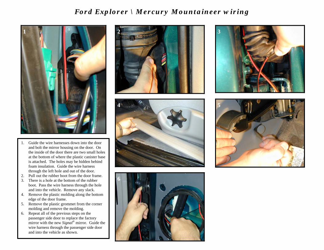
Ford Explorer \ Mercury Mountaineer wiring
1 2 3
4 5
6
1. Guide the wire harnesses down into the door and bolt the mirror housing on the door. On the inside of the door there are two small holes at the bottom of where the plastic canister base is attached. The holes may be hidden behind foam insulation. Guide the wire harness through the left hole and out of the door.
2. Pull out the rubber boot from the door frame. 3. There is a hole at the bottom of the rubber
boot. Pass the wire harness through the hole and into the vehicle. Remove any slack.
4. Remove the plastic molding along the bottom edge of the door frame.
5. Remove the plastic grommet from the corner molding and remove the molding.
6. Repeat all of the previous steps on the passenger side door to replace the factory mirror with the new Signal® mirror. Guide the wire harness through the passenger side door and into the vehicle as shown.

- 5 -
Ford Ranger \ Mazda B-Series wiring
1 2
3 4
1. Remove the plastic molding along the bottom edge of the door frame.
2. Remove the plastic grommet from the corner molding and remove the molding.
3. Pull out the rubber boot from the door.
4. Guide the wire harnesses down into the door and bolt the mirror housing on the door. Guide the wire harness through the hole vacated by the rubber boot. Route a length of gopher wire up into the rubber boot and into the vehicle. Attach the Signal® mirror wire harness to the gopher wire and pull the wire harness into the vehicle. Remove any slack.
5. Repeat all of the previous steps on the passenger side door to replace the factory mirror with the new Signal® mirror.
1 2
3 4

Wire Identification
1. The electrical wiring for the Ford Explorer (not SportTrac) and Mercury Mountaineer is located along the bottom edge of the door frame. The electrical wiring for the Ford Ranger and Mazda B-Series (shown above) is located along the corner of the door frame. The electrical wiring for the Ford Explorer SportTrac is located on the left side of the steering wheel underneath the dash (there is a gray plug with 14 cables). Guide the new wire harnesses from both sides of the vehicle down to the wire bundle. For Explorer (not SportTrac), Mountaineer, Ranger, and B-Series vehicles, locate the GREEN WITH ORANGE STRIPE wire from within the wire bundle. For Explorer SportTrac locate the WHITE WITH RED STRIPE wire from within the wire bundle. Turn the ignition key so that electrical power is on and activate the driver side turn indicator. Probe the wire with the wire tester to verify that flashing turn indicator power is present. Label that wire as ‘driver side turn’.
2. For Explorer (not SportTrac), Mountaineer, Ranger, and B-Series vehicles, locate the ORANGE WITH BLUE STRIPE wire from within the wire
bundle. For Explorer SportTrac locate the BROWN WITH YELLOW STRIPE wire from within the wire bundle. Activate the passenger side turn indicator and probe the wire with the wire tester to verify that flashing turn indicator power is present. Label that wire as ‘passenger side turn’.

- 6 -
1 2
3 4
USE THE INCLUDED WIRE TAPS AND FOLLOW THE FOUR STEPS ABOVE TO SPLICE INTO THE TURN INDICATOR WIRES 1. Make sure the harnesses are routed securely to the wire bundle and enough slack is left for splicing. 2. Splice the RED wire from the driver side harness into the wire previously labeled ‘driver side turn’. 3. Splice the RED wire from the passenger side harness into the wire previously labeled ‘passenger side turn’. 4. Strip and twist together the ends of the black wires from each harness. Crimp them together in the supplied ring connector and
ground to a suitable nearby location on the metal framework of the vehicle. 5. Activate each turn indicator to verify that the Signal® mirrors are working. 6. Replace any door accessories, door panels, plastic moldings, and trim pieces.