shrinkage and cracking of restrained ultra-high-performance fiber-reinforced concrete slabs at early...
TRANSCRIPT
Construction and Building Materials 73 (2014) 357–365
Contents lists available at ScienceDirect
Construction and Building Materials
journal homepage: www.elsevier .com/locate /conbui ldmat
Shrinkage and cracking of restrained ultra-high-performancefiber-reinforced concrete slabs at early age
http://dx.doi.org/10.1016/j.conbuildmat.2014.09.0970950-0618/� 2014 Elsevier Ltd. All rights reserved.
⇑ Corresponding author. Tel.: +82 2 3290 3320; fax: +82 2 928 7656.E-mail address: [email protected] (Y.-S. Yoon).
Doo-Yeol Yoo a, Kyung-Hwan Min b, Joo-Ha Lee c, Young-Soo Yoon a,⇑a School of Civil, Environmental and Architectural Engineering, Korea University, 5-ga, Anam-dong, Seongbuk-gu, Seoul 136-713, Republic of Koreab Research Institute for Engineering and Technology, Chungcheong University, 38 Wolgok-Gil, Gangnae-Myeon, Cheongwon-Gun, Chungcheongbuk-Do 363-792, Republic of Koreac Department of Civil Engineering, The University of Suwon, San 2-2 Wau-ri, Bongdam-eup, Hwaseong-si, Gyeonggi-do 445-743, Republic of Korea
h i g h l i g h t s
� Time-zero is suggested as the deviation point between temperature and shrinkage.� Combined use of SRA and EA has a beneficial effect on strength and free shrinkage.� Higher concrete thickness improves the shrinkage cracking resistance.� Combined use of SRA and EA is beneficial in reducing shrinkage crack width.
a r t i c l e i n f o
Article history:Received 29 April 2014Received in revised form 29 August 2014Accepted 24 September 2014
Keywords:Ultra-high-performance fiber-reinforcedconcreteSlabTime-zeroShrinkageCracking resistanceShrinkage-reducing admixtureExpansive admixture
a b s t r a c t
In this study, the combined effect of shrinkage-reducing admixture (SRA) and expansive admixture (EA)on the shrinkage and cracking behaviors of restrained ultra-high-performance fiber-reinforced concrete(UHPFRC) slabs was investigated. For this investigation, six full-scale UHPFRC slabs with three differentthicknesses (h = 40, 60, and 80 mm) were fabricated using two different mixtures. Test results indicatedthat the combined use of 1% SRA and 7.5% EA is beneficial to improve the mechanical strengths and toreduce the free shrinkage strain of approximately 36–42% at 7 days. Regardless of SRA and EA contents,the slabs with the lowest thickness of 40 mm showed shrinkage cracking at a very early age, while theslabs with higher thicknesses of 60 and 80 mm showed no cracking during testing. However, the UHPFRCslab including 1% SRA and 7.5% EA exhibited a shallow crack with a very small maximum crack width ofbelow 0.04 mm, while the slab without SRA and EA showed through cracks with a large maximum crackwidth of 0.2 mm.
� 2014 Elsevier Ltd. All rights reserved.
1. Introduction
In comparison with other construction materials, concrete hassuperior mechanical properties, durability and economical effi-ciency. However, it has also some limitations including its relativelylow tensile strength, low ductility and low strength to weightratio. In recent years, to overcome these limitations, ultra-high-performance fiber-reinforced concrete (UHPFRC) exhibitingoutstanding strength and ductility as well as exceptional durabilityhas been developed [1,2]. These remarkable properties can beachieved by optimizing the granular mixture based on the packingtheory with a low water-to-binder (W/B) ratio, which homogenizesthe microstructure, and by adding a high volume of steel fibers. In
particular, the superior strengths and unique strain-hardeningbehavior of UHPFRC make it attractive for use in thin plate struc-tures such as thin walls, roofs, and long span bridge decks [3–6].
Despite these advantages, however, the application of UHPFRCin real structures has been limited due to the high cost, lack ofdesign and analysis techniques, and high potential of early-ageshrinkage cracking, of which limited information is available. Fur-thermore, research on the shrinkage cracking behavior of UHPFRCis relatively deficient.
UHPFRC presents very high ultimate autogenous shrinkage ofapproximately 800 le [7] due to the use of low W/B and highfineness admixtures, and a significant part of this shrinkage occursat a very early age [8]. Thus, thin plate structures constructed usingUHPFRC are highly vulnerable to early-age cracking caused by therestraint of shrinkage. For this reason, some researchers [9–12]have recently carried out various restrained shrinkage tests for
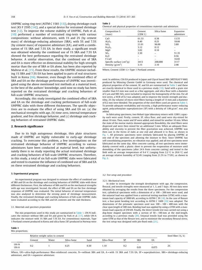
Table 2Chemical and physical properties of cementitious materials and admixture.
Composition %(mass)
Cement(CEM 1)
Silica fume Expansiveadmixture
CaO 61.33 0.38 13.55Al2O3 6.40 0.25 18.66SiO2 21.01 96.00 3.80Fe2O3 3.12 0.12 –MgO 3.02 0.10 –SO3 2.30 – 51.35K2O – – 0.56F-CaO – – 16.02Specific surface (cm2/g) 3413 200,000 3117Density (g/cm3) 3.15 2.10 2.98
Where, Cement (CEM 1) = Type 1 Portland cement.
358 D.-Y. Yoo et al. / Construction and Building Materials 73 (2014) 357–365
UHPFRC using ring-test (ASTM C 1581 [13]), drying shrinkage cracktest (KS F 2595 [14]), and a special device for restrained shrinkagetest [12]. To improve the volume stability of UHPFRC, Park et al.[10] performed a number of restrained ring-tests with variouscompositions: without admixtures, with 1% and 2% (by cementmass) of shrinkage-reducing admixture (SRA), with 5% and 7.5%(by cement mass) of expansive admixture (EA), and with a combi-nation of 1% SRA and 7.5% EA. In their study, a significant resultwas obtained whereby the combined use of 1% SRA and 7.5% EAshowed the best performance regarding the restrained shrinkagebehavior. A similar observation, that the combined use of SRAand EA is more effective on dimensional stability for high-strengthmortar than the use of SRA or EA alone, has been also reported byMaltese et al. [15]. From these results, the UHPFRC mixture includ-ing 1% SRA and 7.5% EA has been applied to parts of real structuresbuilt in Korea [16]. However, even though the combined effect ofSRA and EA on the shrinkage performance of UHPFRC was investi-gated using the above mentioned test methods at a material level,to the best of the authors’ knowledge, until now no study has beenreported on the restrained shrinkage and cracking behaviors offull-scale UHPFRC structures.
Accordingly, this study investigated the combined effect of SRAand EA on the shrinkage and cracking performances of full-scaleUHPFRC slabs with three different thicknesses. The specific objec-tives are to evaluate the effect of using SRA and EA on: (a) themechanical strengths with age, (b) time-zero, internal temperaturegradient, and free shrinkage behavior, and (c) shrinkage and crack-ing behaviors of restrained UHPFRC slabs.
2. Research significance
Due to its high autogenous shrinkage, thin plate structuresmade of UHPFRC are highly vulnerable to early-age shrinkagecracking. To overcome this problem, a few investigations on therestrained shrinkage behavior of UHPFRC according to variousadmixtures have been conducted at material level, but unfortu-nately there is no study reporting the actual restrained shrinkageand cracking behaviors of full-scale UHPFRC structures. Therefore,in this study, a total of six full-scale UHPFRC slabs were fabricatedand tested to examine the influence of combined use of SRA and EAon these restrained shrinkage and cracking behaviors.
3. Experimental program
An experimental program was designed to estimate the effect of combined useof SRA and EA on the shrinkage and cracking behaviors of UHPFRC slabs with threedifferent thicknesses. First, the influence of SRA and EA on the mechanical strengthswith age was investigated. Second, the effect of SRA and EA on the free shrinkageresponses of UHPFRC was evaluated. The initial behavior of internal temperaturewas also analyzed to determine the zeroing point of shrinkage measurement.Finally, the restrained shrinkage and cracking behaviors of full-scale UHPFRC slabswere evaluated according to the SRA and EA contents and the slab thickness.
3.1. Materials and specimen preparation
The mix proportions used in this study are summarized in Table 1. UN-N indi-cates the mixture without SRA and EA and given by Park et al. [17], while UH-Aindicates the mixture with 1% SRA and 7.5% EA. For cementitious materials, Type1 Portland cement produced in Korea and silica fume (SF) produced in Norway were
Table 1Mix proportions.
Relative weight ratios to cement
Cement Water Silica fume Sand
UH-NUH-A
0.2 1 0.25 0.30
Where, UH = ultra-high-performance fiber-reinforced concrete, N = without SRA and Eadmixture, and EA = expansive admixture.
used. In addition, CSA EA produced in Japan and Glycol based SRA (METOLAT P 860)produced by Münzing Chemie GmbH in Germany were used. The chemical andphysical properties of the cement, SF, and EA are summarized in Table 2 and theseare exactly identical to those used in a previous study [10]. Sand with a grain sizesmaller than 0.5 mm was used as a fine aggregate, and silica flour with a diameterof 2 lm and 98% SiO2 were included to improve the homogeneity of the mix. For alltest series, a W/B of 0.2 was adopted, and to improve the tensile strength and duc-tility, 2% (by volume) of micro steel fibers having a length of 13 mm and a diameterof 0.2 mm were blended. The properties of the steel fibers used are given in Table 3.To provide adequate workability and viscosity, a high performance water-reducingagent, polycarboxylate superplasticizer (SP) with a density of 1.06 g/cm3, was alsoadded.
In fabricating specimens, two Hobart type laboratory mixers with 1200 L capac-ity each were used. Firstly, cement, SF, silica flour, and sand were dry-mixed forabout 10 min. Then, water and SP were added, and mixed for another 10 min. Whenthe state of the mortar matrix showed appropriate flowability, the steel fibers weredispersed and were then mixed for an additional 5 min. When an adequate flow-ability and viscosity to prevent the fiber gravitation was achieved, UHPFRC wasthen cast in the forms of slabs at one end and allowed it to flow, as shown inFig. 1. All prismatic specimens were similarly fabricated by placing UHPFRC atone end of the specimen and allowing the mixture to flow. Since UHPFRC hasself-consolidating properties, no vibration was applied, and all test specimens werefabricated on the same day. After concrete casting, all test specimens were imme-diately covered with a plastic sheet to prevent the evaporation of moisture untildemolding of the specimens (after 24 h from concrete casting) and tested in thefield with an average temperature of 9.4 �C (ranging from 2.2 �C to 20.6 �C) andan average relative humidity of 52.4% (ranging from 21.5% to 77.8%), as shown inFig. 2.
3.2. Test setup and procedure
3.2.1. Mechanical testsIn order to investigate the strength development with age, the compressive,
flexural, and tensile strengths were measured at 1, 3, and 7 days. All test data wereobtained by averaging the results from the three specimens. For the compressiontest, cylindrical specimens with a dimension of u 100 � 200 mm were used, andthe uniaxial load was applied from a universal testing machine (UTM) with a max-imum load capacity of 3000 kN, according to ASTM C 39 [18]. In the case of flexuretest, a four-point bending test according to ASTM C 1609 [19] was adopted. Thedimensions of the prismatic specimen used was 100 � 100 � 400 mm with theclear span length of 300 mm. Bending load was applied by using a UTM with a max-imum load capacity of 250 kN. Finally, the direct tensile test was carried out using adog-bone shaped specimen with a section of 50 � 100 mm at the mid-length,according to a previous study [20]. Uniaxial tensile load was provided using thesame UTM as that of the flexure test, and to minimize the secondary flexural stress,the test setup was designed with pin-fixed ends [21].
Steel fiber (Vf, %)
Silica flour SP SRA EA
1.10 0.2�0.01
�0.075
2%
A, A = with 1% SRA and 7.5% EA, SP = superplasticizer, SRA = shrinkage-reducing
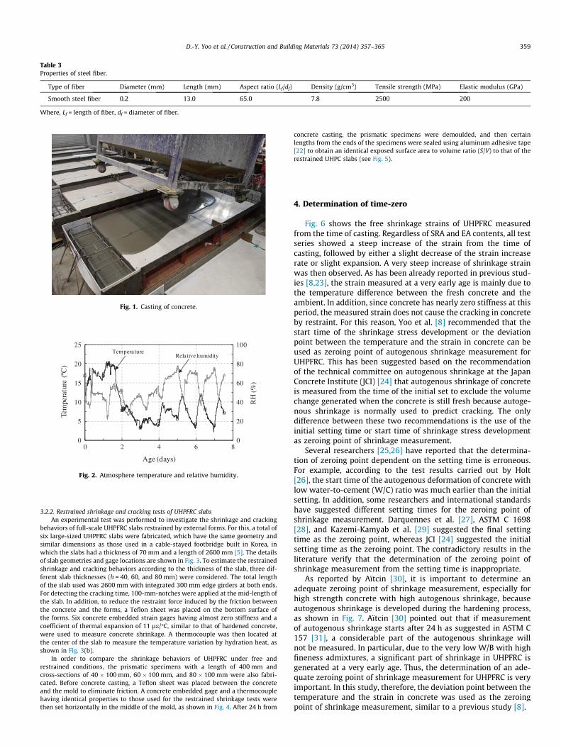
Table 3Properties of steel fiber.
Type of fiber Diameter (mm) Length (mm) Aspect ratio (Lf/df) Density (g/cm3) Tensile strength (MPa) Elastic modulus (GPa)
Smooth steel fiber 0.2 13.0 65.0 7.8 2500 200
Where, Lf = length of fiber, df = diameter of fiber.
Fig. 1. Casting of concrete.
0
20
40
60
80
100
0
5
10
15
20
25
0 2 4 6 8
RH
(%)
Tem
pera
ture
(ºC
)
Age (days)
Relative humidityTemperature
Fig. 2. Atmosphere temperature and relative humidity.
D.-Y. Yoo et al. / Construction and Building Materials 73 (2014) 357–365 359
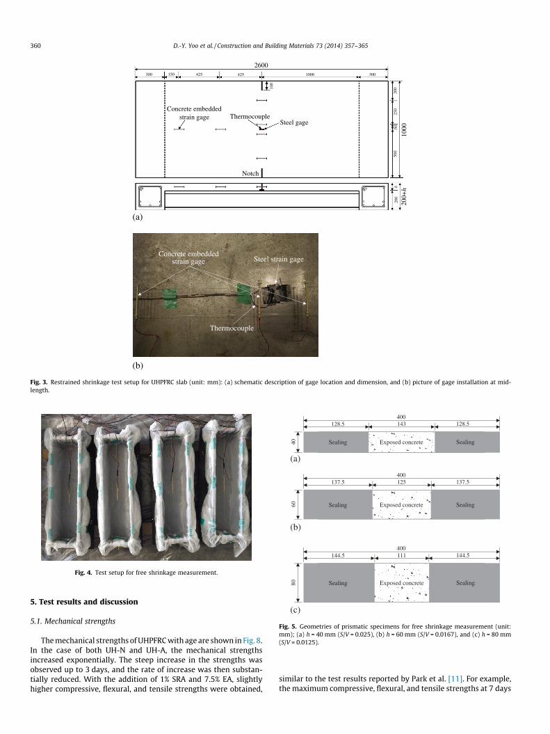
3.2.2. Restrained shrinkage and cracking tests of UHPFRC slabsAn experimental test was performed to investigate the shrinkage and cracking
behaviors of full-scale UHPFRC slabs restrained by external forms. For this, a total ofsix large-sized UHPFRC slabs were fabricated, which have the same geometry andsimilar dimensions as those used in a cable-stayed footbridge built in Korea, inwhich the slabs had a thickness of 70 mm and a length of 2600 mm [5]. The detailsof slab geometries and gage locations are shown in Fig. 3. To estimate the restrainedshrinkage and cracking behaviors according to the thickness of the slab, three dif-ferent slab thicknesses (h = 40, 60, and 80 mm) were considered. The total lengthof the slab used was 2600 mm with integrated 300 mm edge girders at both ends.For detecting the cracking time, 100-mm-notches were applied at the mid-length ofthe slab. In addition, to reduce the restraint force induced by the friction betweenthe concrete and the forms, a Teflon sheet was placed on the bottom surface ofthe forms. Six concrete embedded strain gages having almost zero stiffness and acoefficient of thermal expansion of 11 le/�C, similar to that of hardened concrete,were used to measure concrete shrinkage. A thermocouple was then located atthe center of the slab to measure the temperature variation by hydration heat, asshown in Fig. 3(b).
In order to compare the shrinkage behaviors of UHPFRC under free andrestrained conditions, the prismatic specimens with a length of 400 mm andcross-sections of 40 � 100 mm, 60 � 100 mm, and 80 � 100 mm were also fabri-cated. Before concrete casting, a Teflon sheet was placed between the concreteand the mold to eliminate friction. A concrete embedded gage and a thermocouplehaving identical properties to those used for the restrained shrinkage tests werethen set horizontally in the middle of the mold, as shown in Fig. 4. After 24 h from
concrete casting, the prismatic specimens were demoulded, and then certainlengths from the ends of the specimens were sealed using aluminum adhesive tape[22] to obtain an identical exposed surface area to volume ratio (S/V) to that of therestrained UHPC slabs (see Fig. 5).
4. Determination of time-zero
Fig. 6 shows the free shrinkage strains of UHPFRC measuredfrom the time of casting. Regardless of SRA and EA contents, all testseries showed a steep increase of the strain from the time ofcasting, followed by either a slight decrease of the strain increaserate or slight expansion. A very steep increase of shrinkage strainwas then observed. As has been already reported in previous stud-ies [8,23], the strain measured at a very early age is mainly due tothe temperature difference between the fresh concrete and theambient. In addition, since concrete has nearly zero stiffness at thisperiod, the measured strain does not cause the cracking in concreteby restraint. For this reason, Yoo et al. [8] recommended that thestart time of the shrinkage stress development or the deviationpoint between the temperature and the strain in concrete can beused as zeroing point of autogenous shrinkage measurement forUHPFRC. This has been suggested based on the recommendationof the technical committee on autogenous shrinkage at the JapanConcrete Institute (JCI) [24] that autogenous shrinkage of concreteis measured from the time of the initial set to exclude the volumechange generated when the concrete is still fresh because autoge-nous shrinkage is normally used to predict cracking. The onlydifference between these two recommendations is the use of theinitial setting time or start time of shrinkage stress developmentas zeroing point of shrinkage measurement.
Several researchers [25,26] have reported that the determina-tion of zeroing point dependent on the setting time is erroneous.For example, according to the test results carried out by Holt[26], the start time of the autogenous deformation of concrete withlow water-to-cement (W/C) ratio was much earlier than the initialsetting. In addition, some researchers and international standardshave suggested different setting times for the zeroing point ofshrinkage measurement. Darquennes et al. [27], ASTM C 1698[28], and Kazemi-Kamyab et al. [29] suggested the final settingtime as the zeroing point, whereas JCI [24] suggested the initialsetting time as the zeroing point. The contradictory results in theliterature verify that the determination of the zeroing point ofshrinkage measurement from the setting time is inappropriate.
As reported by Aïtcin [30], it is important to determine anadequate zeroing point of shrinkage measurement, especially forhigh strength concrete with high autogenous shrinkage, becauseautogenous shrinkage is developed during the hardening process,as shown in Fig. 7. Aïtcin [30] pointed out that if measurementof autogenous shrinkage starts after 24 h as suggested in ASTM C157 [31], a considerable part of the autogenous shrinkage willnot be measured. In particular, due to the very low W/B with highfineness admixtures, a significant part of shrinkage in UHPFRC isgenerated at a very early age. Thus, the determination of an ade-quate zeroing point of shrinkage measurement for UHPFRC is veryimportant. In this study, therefore, the deviation point between thetemperature and the strain in concrete was used as the zeroingpoint of shrinkage measurement, similar to a previous study [8].
2600300 425150 425
1000
500
250
200
50
100
1000
Notch
h20
0
200+
h
300
Concrete embedded strain gage Thermocouple
Steel gage
(a)
Concrete embedded strain gage
Thermocouple
Steel strain gage
(b)
Fig. 3. Restrained shrinkage test setup for UHPFRC slab (unit: mm): (a) schematic description of gage location and dimension, and (b) picture of gage installation at mid-length.
Fig. 4. Test setup for free shrinkage measurement.
Sealing SealingExposed concrete
400128.5 143 128.5
40
(a)
Sealing SealingExposed concrete
400137.5 125 137.5
60
(b)
Sealing SealingExposed concrete
400144.5 111 144.5
80
(c)
Fig. 5. Geometries of prismatic specimens for free shrinkage measurement (unit:mm); (a) h = 40 mm (S/V = 0.025), (b) h = 60 mm (S/V = 0.0167), and (c) h = 80 mm(S/V = 0.0125).
360 D.-Y. Yoo et al. / Construction and Building Materials 73 (2014) 357–365
5. Test results and discussion
5.1. Mechanical strengths
The mechanical strengths of UHPFRC with age are shown in Fig. 8.In the case of both UH-N and UH-A, the mechanical strengthsincreased exponentially. The steep increase in the strengths wasobserved up to 3 days, and the rate of increase was then substan-tially reduced. With the addition of 1% SRA and 7.5% EA, slightlyhigher compressive, flexural, and tensile strengths were obtained,
similar to the test results reported by Park et al. [11]. For example,the maximum compressive, flexural, and tensile strengths at 7 days
-1200
-900
-600
-300
0St
rain
(με)
Age (days)
=40mm=60mm=80mm
h
h
h
(a)
-1200
-900
-600
-300
0
0 2 4 6 8
0 2 4 6 8
Stra
in (μ
ε)
Age (days)
=40mm=60mm=80mm
h
h
h
(b)
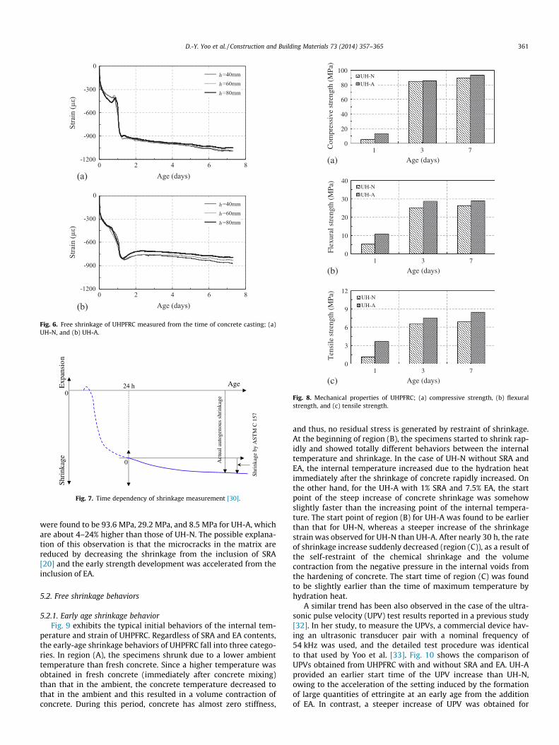
Fig. 6. Free shrinkage of UHPFRC measured from the time of concrete casting; (a)UH-N, and (b) UH-A.
Exp
ansi
onSh
rink
age
024 h Age
Act
ual a
utog
enou
s sh
rink
age
0
Shri
nkag
e by
AST
M C
157
Fig. 7. Time dependency of shrinkage measurement [30].
0
20
40
60
80
100
Com
pres
sive
str
engt
h (M
Pa)
Age (days)
UH-NUH-A
(a)
0
10
20
30
40
Flex
ural
str
engt
h (M
Pa)
Age (days)
UH-NUH-A
(b)
0
3
6
9
12
1 3 7
1 3 7
1 3 7
Ten
sile
str
engt
h (M
Pa)
Age (days)
UH-NUH-A
(c)
Fig. 8. Mechanical properties of UHPFRC; (a) compressive strength, (b) flexuralstrength, and (c) tensile strength.
D.-Y. Yoo et al. / Construction and Building Materials 73 (2014) 357–365 361
were found to be 93.6 MPa, 29.2 MPa, and 8.5 MPa for UH-A, whichare about 4–24% higher than those of UH-N. The possible explana-tion of this observation is that the microcracks in the matrix arereduced by decreasing the shrinkage from the inclusion of SRA[20] and the early strength development was accelerated from theinclusion of EA.
5.2. Free shrinkage behaviors
5.2.1. Early age shrinkage behaviorFig. 9 exhibits the typical initial behaviors of the internal tem-
perature and strain of UHPFRC. Regardless of SRA and EA contents,the early-age shrinkage behaviors of UHPFRC fall into three catego-ries. In region (A), the specimens shrunk due to a lower ambienttemperature than fresh concrete. Since a higher temperature wasobtained in fresh concrete (immediately after concrete mixing)than that in the ambient, the concrete temperature decreased tothat in the ambient and this resulted in a volume contraction ofconcrete. During this period, concrete has almost zero stiffness,
and thus, no residual stress is generated by restraint of shrinkage.At the beginning of region (B), the specimens started to shrink rap-idly and showed totally different behaviors between the internaltemperature and shrinkage. In the case of UH-N without SRA andEA, the internal temperature increased due to the hydration heatimmediately after the shrinkage of concrete rapidly increased. Onthe other hand, for the UH-A with 1% SRA and 7.5% EA, the startpoint of the steep increase of concrete shrinkage was somehowslightly faster than the increasing point of the internal tempera-ture. The start point of region (B) for UH-A was found to be earlierthan that for UH-N, whereas a steeper increase of the shrinkagestrain was observed for UH-N than UH-A. After nearly 30 h, the rateof shrinkage increase suddenly decreased (region (C)), as a result ofthe self-restraint of the chemical shrinkage and the volumecontraction from the negative pressure in the internal voids fromthe hardening of concrete. The start time of region (C) was foundto be slightly earlier than the time of maximum temperature byhydration heat.
A similar trend has been also observed in the case of the ultra-sonic pulse velocity (UPV) test results reported in a previous study[32]. In her study, to measure the UPVs, a commercial device hav-ing an ultrasonic transducer pair with a nominal frequency of54 kHz was used, and the detailed test procedure was identicalto that used by Yoo et al. [33]. Fig. 10 shows the comparison ofUPVs obtained from UHPFRC with and without SRA and EA. UH-Aprovided an earlier start time of the UPV increase than UH-N,owing to the acceleration of the setting induced by the formationof large quantities of ettringite at an early age from the additionof EA. In contrast, a steeper increase of UPV was obtained for
0
5
10
15
20
25
-1000
-800
-600
-400
-200
0
Tem
pera
ture
(ºC
)
Stra
in (μ
ε)
Age (days)
Temp.
Shrinkage
Time-zero
(A) (B)
(a)
0
5
10
15
20
25
-1000
-800
-600
-400
-200
0
0 0.5 1 1.5 2
0 0.5 1 1.5 2
Tem
pera
ture
(ºC
)
Stra
in (μ
ε)
Age (days)
Temp.
Shrinkage
Time-zero
(A) (B)
(b)
(C)
(C)
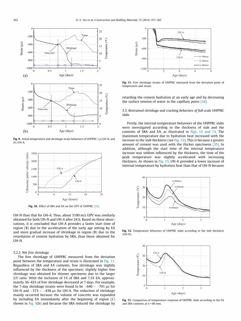
Fig. 9. Initial temperature and shrinkage strain behaviors of UHPFRC; (a) UH-N, and(b) UH-A.
0
700
1400
2100
2800
3500
0 6 12 18 24
Ultr
ason
ic p
ulse
vel
ocity
(m
/s)
Age (hours)
UH-N
UH-A
Fig. 10. Effect of SRA and EA on the UPV of UHPFRC [32].
-1200
-900
-600
-300
0
0 2 4 6 8
Stra
in (μ
ε)
Age (days)
h=40mm
h=60mm
h=80mm
h
h
h
UH-N
UH-A
Fig. 11. Free shrinkage strains of UHPFRC measured from the deviation point oftemperature and strain.
0
10
20
30
40
0 1 2 3
Tem
pera
ture
(ºC
)
Age (days)
h=40mm
h=60mm
h=80mm
Fig. 12. Temperature behaviors of UHPFRC slabs according to the slab thickness(UH-N).
362 D.-Y. Yoo et al. / Construction and Building Materials 73 (2014) 357–365
UH-N than that for UH-A. Thus, about 3100 m/s UPV was similarlyobtained for both UH-N and UH-A after 24 h. Based on these obser-vations, it is concluded that UH-A provides a faster start time ofregion (B) due to the acceleration of the early age setting by EAand more gradual increase of shrinkage in region (B) due to theretardation of cement hydration by SRA, than those obtained forUH-N.
0
10
20
30
40
0 1 2 3
Tem
pera
ture
(ºC
)
Age (days)
UH-N
UH-A
Fig. 13. Comparison of temperature response of UHPFRC slabs according to the EAand SRA contents at h = 80 mm.
5.2.2. Net free shrinkageThe free shrinkage of UHPFRC measured from the deviation
point between the temperature and strain is illustrated in Fig. 11.Regardless of SRA and EA contents, free shrinkage was slightlyinfluenced by the thickness of the specimen; slightly higher freeshrinkage was obtained for thinner specimens due to the largerS/V ratio. With the inclusion of 1% of SRA and 7.5% EA, approxi-mately 36–42% of free shrinkage decreased at 7 days. For example,the 7-day shrinkage strains were found to be �646 – �701 le forUH-N and �373 – �438 le for UH-A. The reduction of shrinkagemainly occurred because the volume of concrete was expandedby including EA immediately after the beginning of region (C)shown in Fig. 9(b) and because the SRA reduced the shrinkage by
retarding the cement hydration at an early age and by decreasingthe surface tension of water in the capillary pores [34].
5.3. Restrained shrinkage and cracking behaviors of full-scale UHPFRCslabs
Firstly, the internal temperature behaviors of the UHPFRC slabswere investigated according to the thickness of slab and thecontents of SRA and EA, as illustrated in Figs. 12 and 13. Themaximum temperature due to hydration heat increased with theincrease in the slab thickness (see Fig. 12). This is because a greateramount of cement was used with the thicker specimens [35]. Inaddition, although the start time of the internal temperatureincrease was seldom influenced by the thickness, the time of thepeak temperature was slightly accelerated with increasingthickness. As shown in Fig. 13, UH-A provided a lower increase ofinternal temperature by hydration heat than that of UH-N because
400
700
1000
-800
-600
-400
-200
0
200
Stra
in (μ
ε)
Age (days)
Cracking point
Free shrinkage
Restrained shrinkage
(a) 0 2 4 6 8
D.-Y. Yoo et al. / Construction and Building Materials 73 (2014) 357–365 363
UH-A includes SRA and a slightly lower amount of cement thanUH-N. The reduction of the maximum heat flow values by addingSRA has previously been reported by Sant et al. [36].
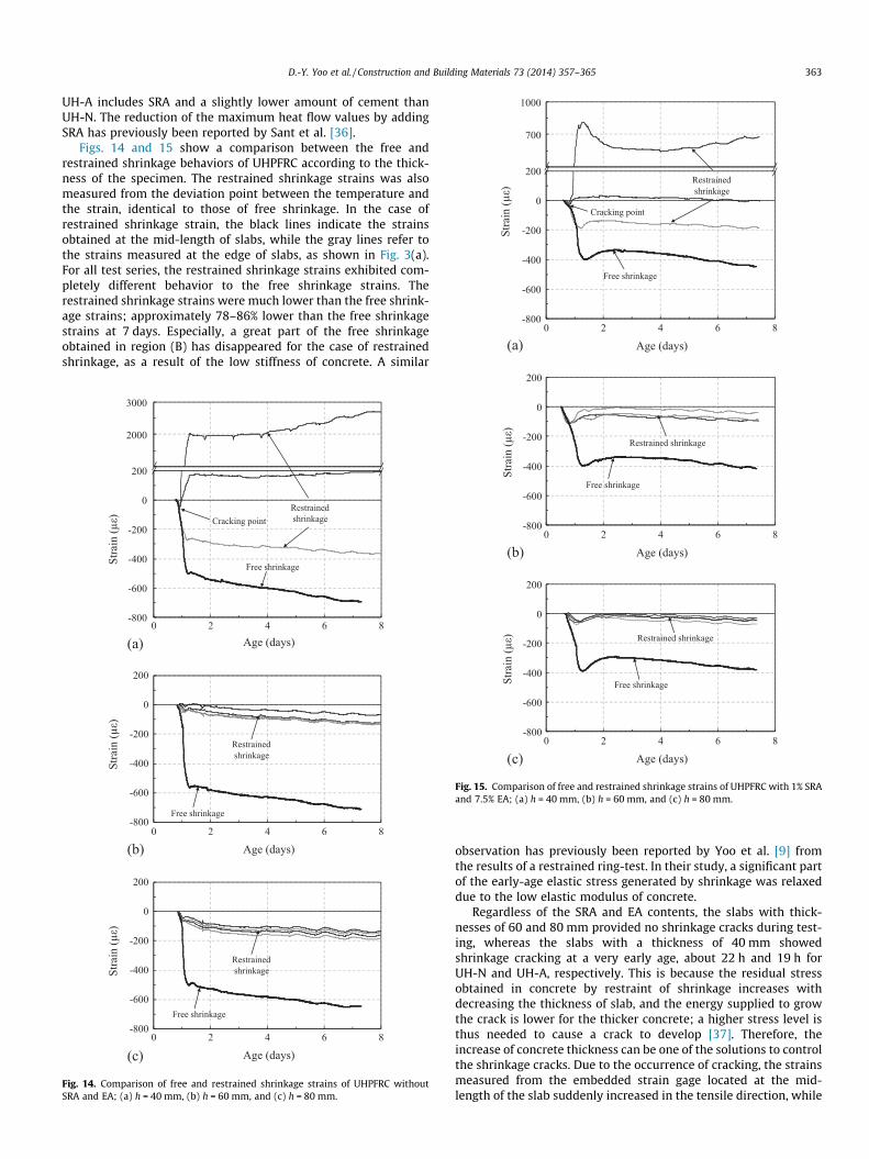
Figs. 14 and 15 show a comparison between the free andrestrained shrinkage behaviors of UHPFRC according to the thick-ness of the specimen. The restrained shrinkage strains was alsomeasured from the deviation point between the temperature andthe strain, identical to those of free shrinkage. In the case ofrestrained shrinkage strain, the black lines indicate the strainsobtained at the mid-length of slabs, while the gray lines refer tothe strains measured at the edge of slabs, as shown in Fig. 3(a).For all test series, the restrained shrinkage strains exhibited com-pletely different behavior to the free shrinkage strains. Therestrained shrinkage strains were much lower than the free shrink-age strains; approximately 78–86% lower than the free shrinkagestrains at 7 days. Especially, a great part of the free shrinkageobtained in region (B) has disappeared for the case of restrainedshrinkage, as a result of the low stiffness of concrete. A similar
1000
2000
3000
-800
-600
-400
-200
0
200
Stra
in (μ
ε)
Age (days)
Cracking point
Free shrinkage
Restrained shrinkage
(a)
-800
-600
-400
-200
0
200
Stra
in (μ
ε)
Age (days)
Free shrinkage
Restrained shrinkage
(b)
-800
-600
-400
-200
0
200
0 2 4 6 8
0 2 4 6 8
0 2 4 6 8
Stra
in (μ
ε)
Age (days)
Free shrinkage
Restrained shrinkage
(c)
Fig. 14. Comparison of free and restrained shrinkage strains of UHPFRC withoutSRA and EA; (a) h = 40 mm, (b) h = 60 mm, and (c) h = 80 mm.
-800
-600
-400
-200
0
200
Stra
in (μ
ε)
Age (days)
Free shrinkage
Restrained shrinkage
(b)
-800
-600
-400
-200
0
200
0 2 4 6 8
0 2 4 6 8
Stra
in (μ
ε)
Age (days)
Free shrinkage
Restrained shrinkage
(c)
Fig. 15. Comparison of free and restrained shrinkage strains of UHPFRC with 1% SRAand 7.5% EA; (a) h = 40 mm, (b) h = 60 mm, and (c) h = 80 mm.
observation has previously been reported by Yoo et al. [9] fromthe results of a restrained ring-test. In their study, a significant partof the early-age elastic stress generated by shrinkage was relaxeddue to the low elastic modulus of concrete.
Regardless of the SRA and EA contents, the slabs with thick-nesses of 60 and 80 mm provided no shrinkage cracks during test-ing, whereas the slabs with a thickness of 40 mm showedshrinkage cracking at a very early age, about 22 h and 19 h forUH-N and UH-A, respectively. This is because the residual stressobtained in concrete by restraint of shrinkage increases withdecreasing the thickness of slab, and the energy supplied to growthe crack is lower for the thicker concrete; a higher stress level isthus needed to cause a crack to develop [37]. Therefore, theincrease of concrete thickness can be one of the solutions to controlthe shrinkage cracks. Due to the occurrence of cracking, the strainsmeasured from the embedded strain gage located at the mid-length of the slab suddenly increased in the tensile direction, while
(a)
Crack
Notch
UH-A-40
(b)
Cracks
UH-N-40
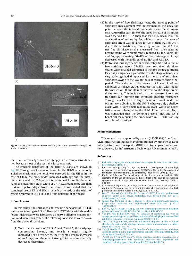
Fig. 16. Cracking response of UHPFRC slabs; (a) UH-N with h = 40 mm, and (b) UH-A with h = 40 mm.
364 D.-Y. Yoo et al. / Construction and Building Materials 73 (2014) 357–365
the strains at the edge increased steeply in the compressive direc-tion because most of the restraint force was lost.
The cracking behaviors of the UHPFRC slabs are shown inFig. 16. Through cracks were observed for the UH-N, whereas onlya shallow crack near the notch was observed for the UH-A. In thecase of UH-N, the crack width increased with age and the maxi-mum crack width at 7 days was found to be 0.2 mm. On the otherhand, the maximum crack width of UH-A was found to be less than0.04 mm up to 7 days. From this result, it was noted that thecombined use of EA and SRA is beneficial to reduce the width ofcracks occurred in UHPFRC slabs from restraint of shrinkage.
6. Conclusions
In this study, the shrinkage and cracking behaviors of UHPFRCslabs were investigated. Six full-scale UHPFRC slabs with three dif-ferent thicknesses were fabricated using two different mix propor-tions and were then tested. The following conclusions were drawnfrom the above discussions:
(1) With the inclusion of 1% SRA and 7.5% EA, the early-agecompressive, flexural, and tensile strengths slightlyincreased. For all test series, the strengths steeply increasedup to 3 days, and the rate of strength increase substantiallydecreased thereafter.
(2) In the case of free shrinkage tests, the zeroing point ofshrinkage measurement was determined as the deviationpoint between the internal temperature and the shrinkagestrain. An earlier start time of the steep increase of shrinkagewas observed for UH-A than that for UH-N because of theacceleration of setting by EA, while a steeper increase ofshrinkage strain was obtained for UH-N than that for UH-Adue to the retardation of cement hydration from SRA. Thenet free shrinkage strains measured from the suggestedzeroing point were significantly reduced by including SRAand EA; approximately 36–42% of free shrinkage at 7 daysdecreased with the addition of 1% SRA and 7.5% EA.
(3) Restrained shrinkage behavior considerably differed to that offree shrinkage. About 78–86% lower restrained shrinkagestrains were obtained, compared to the free shrinkage strains.Especially, a significant part of the free shrinkage obtained at avery early age had disappeared for the case of restrainedshrinkage, owing to the low stiffness of concrete during thatperiod. The slabs with the lowest thickness of 40 mmexhibited shrinkage cracks, whereas the slabs with higherthicknesses of 60 and 80 mm showed no shrinkage cracksduring testing. This indicated that the increase of concretethickness can improve the shrinkage cracking resistance.Through cracks with a large maximum crack width of0.2 mm were obtained for the UH-N, whereas only a shallowcrack with a very small maximum crack width of below0.04 mm was observed for the UH-A. From these results, itwas concluded that the combined use of SRA and EA isbeneficial for reducing the crack width in UHPFRC slabs byrestraint of shrinkage.
Acknowledgments
This research was supported by a grant (13SCIPA01) from SmartCivil Infrastructure Research Program funded by Ministry of Land,Infrastructure and Transport (MOLIT) of Korea government andKorea Agency for Infrastructure Technology Advancement (KAIA).
References
[1] Richard P, Cheyrezy M. Composition of reactive powder concretes. Cem ConcrRes 1995;25(7):1501–11.
[2] Kim SW, Park JJ, Kang ST, Ryo GS, Koh KT. Development of ultra highperformance cementitious composites (UHPCC) in Korea. In: Proceedings ofthe fourth international IABMAS conference, Seoul, Korea; 2008. p. 110.
[3] Kobler M, Sobek W. The introduction of high forces into tine-walled UHPCelements by the use of implants. In: Proceedings of the second internationalsymposium on ultra high performance concrete, Kassel, Germany; 2008. p.683–90.
[4] di Prisco M, Lamperti M, Lapolla S, Khurana RS. HPFRCC thin plates for precastroofing. In: Proceedings of the second international symposium on ultra highperformance concrete, Kassel, Germany; 2008. p. 675–82.
[5] Lee CD, Kim WJ, Cho KS, Kim JH. Design of UHPC(ultra high performanceconcrete) girder cable stayed footbridge. Mag Korea Concr Inst 2011;23(5):38–44 (in Korean).
[6] Saleem MA, Mirmiran A, Xia J, Mackie K. Ultra-high-performance concretebridge deck reinforced with high-strength steel. ACI Struct J 2011;108(5):601–9.
[7] Koh KT, Ryu GS, Kang ST, Park JJ, Kim SW. Shrinkage properties of ultra-highperformance concrete (UHPC). Adv Sci Lett 2011;4(3):948–52.
[8] Yoo DY, Park JJ, Kim SW, Yoon YS. Influence of reinforcing bar type onautogenous shrinkage stress and bond behavior of ultra high performance fiberreinforced concrete. Cem Concr Compos 2014;48:150–61.
[9] Yoo DY, Park JJ, Kim SW, Yoon YS. Influence of ring size on the restrainedshrinkage behavior of ultra high performance fiber reinforced concrete. MaterStruct 2014;47(7):1161–74.
[10] Park JJ, Yoo DY, Kim SW, Yoon YS. Benefits of using expansive and shrinkagereducing agents in ultra-high-performance concrete for volume stability. MagConcr Res 2014;66(14):745–50.
[11] Park JJ, Yoo DY, Kim SW, Yoon YS. Drying shrinkage cracking characteristics ofultra-high-performance fibre reinforced concrete with expansive andshrinkage reducing agents. Mag Concr Res 2013;65(4):248–56.
D.-Y. Yoo et al. / Construction and Building Materials 73 (2014) 357–365 365
[12] Habel K, Charron JP, Denarie E, Bruhwiler E. Autogenous deformations andviscoelasticity of UHPFRC in structures. Part 1: Experimental results. MagConcr Res 2006;58(3):135–45.
[13] American Society for Testing and Materials (ASTM). ASTM C 1581 Standardtest method for determining age at cracking and induced tensile stresscharacteristics of mortar and concrete under restrained shrinkage. In: Annualbook of ASTM standards. West Conshohocken, PA: ASTM; 2009.
[14] Korea Standard Association (KSA). KS F 2595 Standard test method for dryshrinkage crack in concrete 2009;Seoul. in Korean.
[15] Maltese C, Pistolesi C, Lolli A, Bravo A, Cerulli T, Salvioni D. Combined effect ofexpansive and shrinkage reducing admixtures to obtain stable and durablemortars. Cem Concr Res 2005;35(12):2244–51.
[16] Kim YJ, Park SY, Park JS, Kim BS. State-of-the-art of UHPC applications in theWorld. Korean Soc Civil Eng 2013;61(2):39–50 (in Korean).
[17] Park JJ, Kang ST, Koh KT, Kim SW. Influence of the ingredients on thecompressive strength of UHPC as a fundamental study to optimize themixing proportion. In: Fehling E, Schmidt M, St}urwald S, editors. Proceeding ofsecond international symposium on ultra high performance concrete,Germany. Germany: Kassel University; 2008. p. 105–12.
[18] American Society for Testing and Materials (ASTM). ASTM C 39/C 39M Standardtest method for compressive strength of cylindrical concrete specimens. In:Annual book of ASTM standards. West Conshohocken, PA: ASTM; 2012.
[19] American Society for Testing and Materials (ASTM). ASTM C 1609/C 1609MStandard test method for flexural performance of fiber-reinforced concrete(using beam with third point loading). In: Annual book of ASTMstandards. West Conshohocken, PA: ASTM; 2006.
[20] Yoo DY, Kang ST, Lee JH, Yoon YS. Effect of shrinkage reducing admixture ontensile and flexural behaviors of UHPFRC considering fiber distributioncharacteristics. Cem Concr Res 2013;54:180–90.
[21] Kanakubo T. Tensile characteristics evaluation method for ductile fiber-reinforced cementitious composites. J Adv Concr Technol 2006;4(1):3–17.
[22] See HT, Attiogbe EK, Miltenberger MA. Shrinkage cracking characteristics ofconcrete using ring specimens. ACI Mater J 2003;100(3):239–45.
[23] Yoo DY, Shin HO, Yang JM, Yoon YS. Material and bond properties of ultra highperformance fiber reinforced concrete with micro steel fibers. Compos Part BEng 2014;58:122–33.
[24] Japan Concrete Institute. Committee report. Autogenous shrinkage of concrete.In: Tazawa E, editor, E&FN Spon; 1999. p. 3–62.
[25] Hammer TA, Justnes H, Bjøntegaard Ø, Sellevold EJ. Suggestions on theterminology and the test methods proposed by JCI. Autogenous Shrinkage ofconcrete. In: Tazawa E, editor. Proceedings of the internationalworkshop. E&FN Spon; 1998. p. 397–9.
[26] Holt E. Early age autogenous shrinkage of concrete. Tech Res Centre Finland:VTT Publicat 2001;446:1–184.
[27] Darquennes A, Staquet S, Espion B. Determination of time-zero and its effecton autogenous deformation evolution. Eur J Environ Civil Eng 2011;15(7):1017–29.
[28] American Society for Testing and Materials (ASTM). ASTM C 1698 Standardtest method for autogenous strain of cement paste and mortar. In: Annualbook of ASTM standards. West Conshohocken, PA: ASTM; 2009.
[29] Kazemi-Kamyab H, Denarié E, Brühwiler E. Very early age stiffnessdevelopment of UHPFRC matrices in low temperatures. In: Proceedings 8thfib PhD symposium in Kgs, yngby, Denmark; 2010.
[30] Aïtcin PC. Demystifying autogenous shrinkage. Conc Int 1999;21(11):54–6.[31] American Society for Testing and Materials (ASTM). ASTM C 157/C 157M
Standard test method for length change of hardened hydraulic-cement mortarand concrete. In: Annual book of ASTM standards. West Conshohocken,PA: ASTM; 2008.
[32] Ahn MY, Evaluating setting and early age strength of Ultra-High PerformanceConcrete(UHPC) by Ultrasonic Pulse Velocity (UPV) method, Mater’s Thesis,Korea University, Seoul, Korea.
[33] Yoo DY, Park JJ, Kim SW, Yoon YS. Early age setting, shrinkage and tensilecharacteristics of ultra high performance fiber reinforced concrete. ConstrBuild Mater 2013;41:427–38.
[34] Bentz DP. Influence of shrinkage-reducing admixtures on early-age propertiesof cement pastes. J Adv Concr Tech 2006;4(3):423–9.
[35] Yang EH, Yang Y, Li VC. Use of high volume of fly ash to improveECC mechanical properties of material greenness. ACI Mater J 2007;104(6):620–8.
[36] Sant G, Lothenbach B, Juilland P, Le Saout G, Weiss J, Scrivener K. The origin ofearly age expansions induced in cementitious materials containing shrinkagereducing admixtures. Cem Concr Res 2011;41(3):218–29.
[37] Hossain AB, Weiss J. The role of specimen geometry and boundary conditionson stress development and cracking in the restrained ring test. Cem Concr Res2006;36(1):189–99.