shielding - ntuemc.twntuemc.tw/upload/file/20120419205538a0439.pdf · low frequency, magnetic...
TRANSCRIPT

Shielding

Introduction
Concept of shielding


Shielding of a metal shield (theory)
. . 20logi
t
ES E
E
For E field
For H field
. . 20logi
t
HS E
H
Do they be equal ?

Shielding of a metal shield (theory)
It depends. For plane wave, they are equal But for near field, they are not.

Shielding of a metal shield (theory)
0
22 / 2 /0 0
0 0
( )[1 ( ) ]
4
j tt j t t j ti
t
Ee e e e e
E
j
j
where :Skin depth
1. Plane wave assumption 2. Continuity of E and H at each boundary
How to derive?

11.1 Shielding effectiveness. (S.E.)
a. Definition
ˆ1 : . . 20 log
ˆ
ˆ2 : . . 20 log
ˆ
note:
1. If the incident field is an uniform plane wave,and the me
t
t
Eifor electric firld S E
E
Hifor magnetic field S E
H
tan
dium on
each side of the barrier are identical, 1 and 2 definitions are
identical.
2. For near fields and/or different medium, 1 and 2 are not
equivalent.
ˆ3. Definition 1 (for E field) is taken as s dard for 2 case.

-
1
( : )
.
(1) Re .
(2) :
(3)
: (1) & (2) . . , (3)
zattenuation
C Causes of shield
flection
Absorption e
Multiple reflection
Note will increase the S E of the barrier but will decrease
t
. . .
. . dB dB dB dB
he S E of barrier
S E R A M

11.2 Shielding effectiveness: far field sources
0
0
0
0
-
-
0
-
-
0
-1 1
11.2.1.
(1) :
ˆ ˆ
ˆˆ
ˆ ˆ
ˆˆ -
ˆ ˆ
j zi xi
j zii y
j zr r x
j zrr y
zx
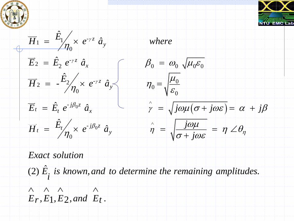
Exact solution
For plane wave
E E e a
EH e a
E E e a
EH e a
E E e a
0
-110
-2 2 0 0 0 0
- 022 00 0
-
ˆˆ
ˆ ˆ
ˆˆ -
ˆ ˆ
zy
zx
zy
j zt t x
EH e a where
E E e a
EH e a
E E e a
0-
0
ˆˆ
j ztt y
j j j
jEH e aj
ˆ(2) , .
, , , .1 2
Exact solution
E is known and to determine the remaining amplitudesi
E E E and Er t

. . 0 1 2 1 2
1 2 1 2
0 0 0 0
1 2
B C at Z E E E E E E E Ei r i r
E E E Ei rH H H Hi r
at Z t E E E
- - - 1 2
- - - 1 2 - 1 2
0 0 0
2
0 -2- - 2203 . 1 ( )
40 0
t t tE e E e E et t
E E Et t ttH H H e e et
tj t
e e
-0
. 1/ , .
t j tj te e e
exact solution where j in barrier metal

0
0
0
-- - - -
4 Simplifications:
1. assume the barrier is a "good conductor".
- 1.
2. skin depth barrier thickness .
1
tt t j t j t
t
e e e e e
E
2
0 - -0
0
4 4
t ti
t
e e
E

0
10 10
0
10 10
2
-2- 20
0
5
. . : 20 log : , 20 log : .
4
6 The Multiple - reflection term is the middle term of (3).
. 20 log 20 log .
4
- 20 log 1 -
t
dB dB
t
dB dB
tj
dB
P S R e A
S E e M
M e e
- 2-2
( )
1 .
20 log 1 - 0
t
j tt
if t
where for good conductor
e e

11.2.2 Approximate solution
0
2
1
0
0
01
ˆ: 1 ( )
2
. Re ( )
0.
ˆ ˆ21
ˆ ˆ
ˆ 22
ˆ ˆ
i
t
Assumption a good conductor
t
a flection Loss E field
t
E
E
E
E
E

01
21
0
2
0 010
0
.
ˆ
3
ˆˆ ˆ4
ˆ
ˆˆ4 20 log 20 log 20 log
ˆ ˆ4 4
tt
i i
idB
t
the same as exact solution
E
In the absence of attenuation
EE E
E E E
ER
0
0
ˆ
:
ˆ2 0 1, 2
ˆ
2.
Note The transimission coefficient is very small
at the Boundary and is approximately
at the Boundary
ve
.1. ry little of E field is transmitted through the B
1
1 1 0 0
0
0
0
0
01 1 1 0
21 2
22 0
i i i
t
t t
E
H E
H E E
if
EH E
H E E
0
0
2
0
43
t t t
i i i
if
H H H
H H H

1
C. Absorption loss
is attenuated in the conductor.
Absorption factor
20log t t
dB
E
A Ae e
0
2
0
Note:
ˆ41.
ˆ
2. But primary transmission of H field occurs at the boundary 1,whereas
the primary transmission of the E field occurs at the boundary 2.
3. It means that "thick
t t
i i
E H
E H
" boundary has more effect on shielding against H
field than to the E field.

d. Multiple Reflection Loss
When t >>δ the multiple reflection loss may be important.
(1) for magnetic field
1.
in
inEinHt
H
HTHTH
ˆˆ
ˆ2
ˆˆˆˆˆˆ
0
0
1

inH
t1H
t 2H
boundary 1 boundary 2

2. The reflected wave is
3.
2 ˆ
ˆˆ
ˆ
1 ˆ
22
0
0
boundaryatHe
He
boundaryatHe
inrt
E
inrt
inrt
E
inrt
EHt HeTH ˆˆˆ 22
2

4.
5.
1 , )1(
ˆ
1ˆ
ˆˆˆˆ
21
42
1
321
t
rtE
rtE
rtEt
tttt
H
eleteeH
HHHH
421 1log20ˆ
ˆlog20
ˆ
ˆlog20
i
t
i
tdB
H
H
H
HSE

6.
2
20
0
22
20
0
ˆ20log 1
ˆ
ˆ20log 1
ˆ
t
dB
tj tβς
η ηM e
η η
η η e e
η η
same as exact solution

§11.3 Shielding effectiveness - near field sources
a. In the far field:
0
0
3 )3(
)2(
)1(
d
HE
orthogonalareHandE

b. Near field for Hertzian dipole
(1)
2 30
0 0
0
20
0
3
0 0
0
02
0
ˆˆ
ˆ 1
901
w
j j jr r rE
ZjH
r r
j
r
rr
(2)
(3)
0 0
0
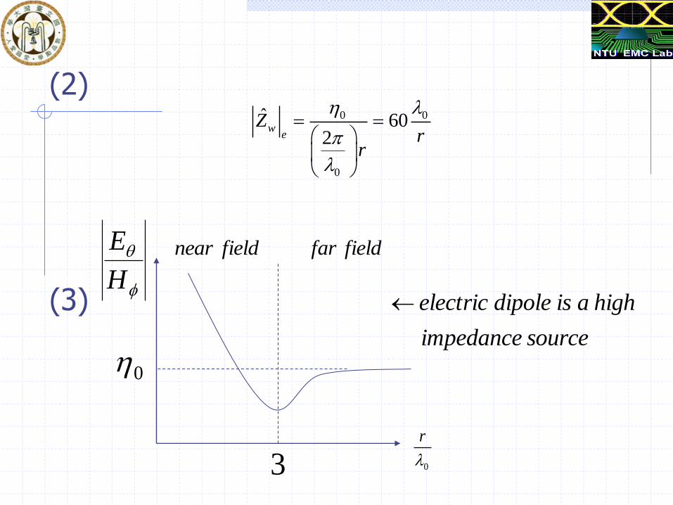
ˆ 602
we
Zr
r
fieldnear fieldfar
3
0
H
E
0
r
sourceimpedance
highaisdipoleelectric

c. Near field for magnetic dipole (loop)
(1)
20
0
0
2 30
0 0
0 0
1ˆ
ˆˆ 1 1
90
w
jrE r
ZjH
r r r
r

(2)
(3)
23692ˆ
0
0
fZ
mw
fieldnear fieldfar
3
0
H
E
0
fieldnear
theinsourceimpedance
lowaisdipolemagnetic

d. Reflection loss for Electric source
(1) we know for plane wave
(2)
ˆ4
20logˆ4
ˆ20log
ˆ
ˆlog20
0
0
2
0
t
idB
E
ER
0
0
0
3 2
ˆusing
ˆ20log 322 10log
ˆ4
w
w r
dB
r
Z jr
ZR
f r
fieldnear

Shielding of a metal shield (Near Field)
060wZr
0
2369w
rZ
Electric dipole
Magnetic dipole

Shielding of a metal shield (Near Field)
3 2322 10log( )r
e
r
Rf r
2
14.57 10log( )rm
r
frR
For electric dipole
For magnetic dipole

Shielding of a metal shield (Near Field)
1. Reflection Loss increase as frequency decrease for E field 2. Reflection Loss decrease as frequency decrease for H field
Note: The Absorption loss also Decrease as frequency decrease for H-field.
How to solve the SE of magnetic field?
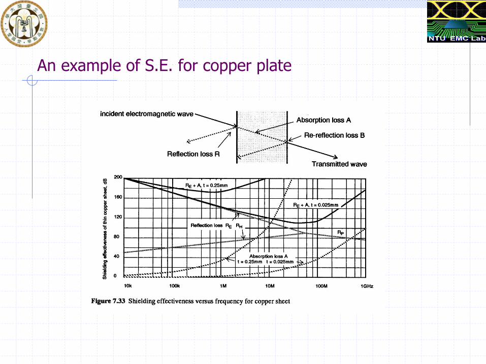
An example of S.E. for copper plate

Low Frequency, Magnetic Shielding
Two approaches

Low Frequency, Magnetic Shielding
Two factors that may degrade the ferromagnetic material: 1. Increasing frequency. 2. Increasing the field strength.
Larger than 4KHz, the u is the same with the steel
That’s why we use the steel as
The magnetic shielding material for Switch-mode Power Supply (20-100KHz).

Low Frequency, Magnetic Shielding
Phenomenon of the saturation of ferromagnetic materials
saturation
When increase the H-field

Low Frequency, Magnetic Shielding
Solution: Using multi-layer to reduce the effect of the saturation

The effect of aperture
In practice, the S.E. is limited by the necessary apertures and discontinuities.
20log2
SEd
The simplest formula
The modified formula
Ex: 20dB SE for 1GHz then, d < 1.6cm
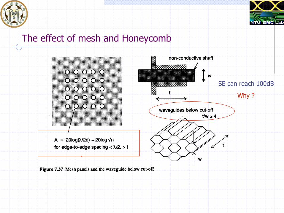
The effect of mesh and Honeycomb
SE can reach 100dB
Why ?

The effect of Seams
Poor Better
Best
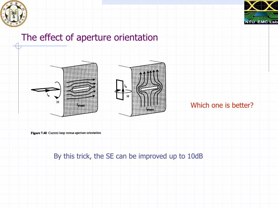
The effect of aperture orientation
Which one is better?
By this trick, the SE can be improved up to 10dB

The effect of image plane

Enclosure resonance
2 2 2150 ( / ) ( / ) ( / )F k l m h n w MHz
F ~ 212/l ~ 212/h ~ 212/w for equal square enclosure

Gasket and Contact Strip
Choosing concern: 1. Conductivity 2. Ease of mounting

Measurement of SE
Method 1: EN50147-1

. . .b Measurement of S E

Measurement of SE
Method two: Coaxial transmission line model