shafilc i. rifaat,
TRANSCRIPT

REINFORCED CONCRETE.
MODULAR ROOF UNIT.
By
Shafilc I. Rifaat,
N.,,
B.Arch. Alexandria University, 1960.
SUBMITTED IN PARTIAL FULFILLMENT
OF THE REQUIREMENTS FOR THE
DEGREE OF MASTER IN ARCHITECTURE
AT THE
MASSACHUSETTS INSTITUTE OF TECHNOLOGY
JULY 1962.
Signature of Author
Signature of Thesis Supervi
Signature of Head of Department
Shafik I.' Rifaat.
Prof. Eduardo F. Catalano.
Prof. Lawrence B. Anderson.
July 27,1962.
Pietro Belluschi, DeanSchool of Architecture and PlanningMassachusetts Institute of TechnologyCambridge 39, Massachusetts.
Dear Dean Belluschi :
In partial fulfillment of the requirements for the
degree of Master in Architecture, I hereby submit
this thesis entitled, " Reinforced Concrete Modular
Roof Unit."
Respectfully,
Shafik I. Rifaat.
ACKNOWLEDGEMENTS
I should like to thank the following
for their advice and criticism during
the course of this study
Professor Eduardo F. Oatalano
Massachusetts Institute of Technology
and
Professor Howard Simpson
Professor Giulio Pizzetti
Professor A. G. Harris.

TABLE OF CONTENTS Page
Program . . . . . . . . . . . . . . . . . . . . . . .1
Introduction . . . . . . . . . . . . . . . . . . . . 2
Objectives . . . . . . . . . . . . . . . . . . . . . 3
Structural System . . . . . . . . . . . . . . . . . .4
Final study . . . . . . . . . . . . . . . . . . .7
Structural analysis . . . . . . .... . . .. .10
Design of different parts .. ...... 0. 0 .13
Quality of spaces . . #. .. .. .. ... . ... .25
Admittance of light . . . . . . . . . . . . . . . . .25
Ventilation . . . . . . . . . .. . . . . .. . . . . 27
Acoustics . . . . . . . . . . . . . . . . . . . . .27
Thermal insulation . . . . . . . . . . . . . . . . * 28
Subdivision of space . . . . . . . . . . . . . . . . 29
Construction . ..... . .... . . . . . . . .. 30
Conclusion . . . . . . . . . .*........ . . . 31

REINFORCED CONCRETE MODULAR ROOF UNIT.
By
Shafik I. Rifaat.
Submitted in partial fulfillment of the requirements
for the dgree of Master in Architecture in the Department
of Architecture, on July 27,1962.
Program.
THE USE OF REINFORCED CONCRETE :
Project 0. Design of a MODULAR ROOF UNIT for schools,
shopping centers, or other one-story buildings.
Span : from 30 to 40 feet.
Space defined by a peripheral low horizontal area, and a
central high area of varied forms. Natural and / or
artificial light.
- 1 -

INTRODUCTION
Free education, to eradicate ignorance in the developing
countries, is a must. In Egypt, there is an urgent and
immediate need for primary schools. The number of students,
between the ages 6-12 years, in need of primary education,
who cannot find schools to accomodate them, are about
1,550,000 students. If we consider a primary school,
that has six stages of education, with three classrooms
per stage, and 35 students per classroom, then we will
need approximatly 2,460 primary schools, each consisting
of 18 classrooms, with a total number of 44,300 classrooms.
The aim of this thesis, is to direct the design and the
development, of a - modular roof unit, spanning from
9-12 meters, ( 30 - 40 feet), a space defined by a
peripheral low horizontal area and a central high one -
to form a classroom, self-contained, flexible within
itself, to allow and facilitate the teaching and other
activities to take place, and to form a system of growth,
of which this unit is the component.
- 2 -

OBJECTIVES
The unit should be designed to suit the Egyptian enviroment.
Both the simplicity of errection, and the lowering of the
total cost, without affecting the quality, are essential.
There should be maximum usage of natural resources, such
as day-light for lighting, and natural air movement for
cross-ventilation.
The following studies, have been a useful guide, to reach
the final architectonic expression of this unit :
1- Structural system
2- Quality of spaces
3- Admittance of light
4- Ventilation
5- Acoustics
6- Weather insulation
7- Subdivision of space
8- Construction.
- 3 -

1- STRUCTURAL SYSTEM
Structural analyses, based on logical assumptions have been
studied, to attain maximum usage of the space enclosed,
and to obtain best performance of the material, Reinforced
Concrete. This is achieved through the geometrical
arrangement of the surfaces, and the system of supports.
Assumptions :
- The continuity of surfaces is essential; the low
horizontal area and the high one, should act together to
reduce the stresses in the structure.
- The structure should be carried on four supports, to
produce practical spans, and load distribution.
- The logical position of the four supports, is shown
in figure -C-, where the columns can support both, the
low horizontal area, and the high one, as well as reducing
the moments and shearing forces , ( stresses ) , in the
structure; as shown in the simple diagrams A, B, and C.
- The proportion of the cantilevers to the main span,
should not exceed 1:3:1; this gives equal positive and
negative moments under uniform distributed loading.
( Figure 2 , page 5. )
- 4 -

1Oft 30 ft 1Oft
Figure 1
I -II I
I II II I
L~ ~1
A
aI II I
I II IL _ - _
* I II
--- *~1~-~--
Figure 2
-5 -
5
3 m
9 m
3 m
I.
L
0
-- 4
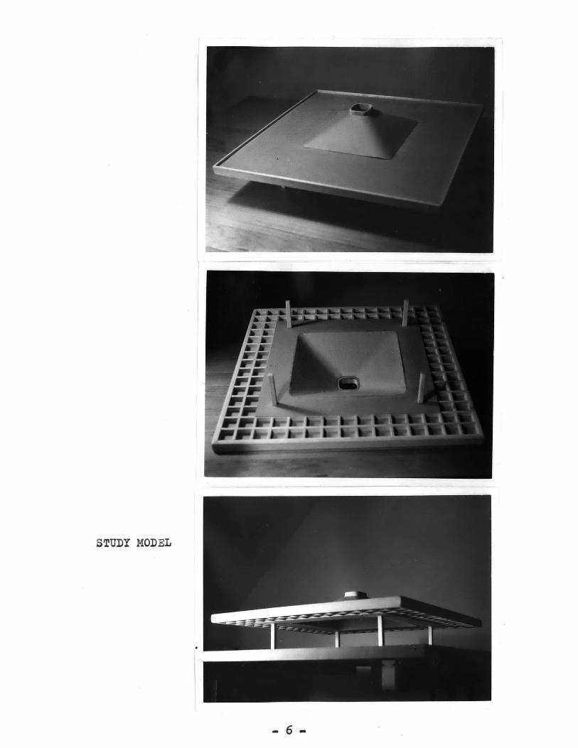
STUDY MODEL
-6 -

Final study
General description :
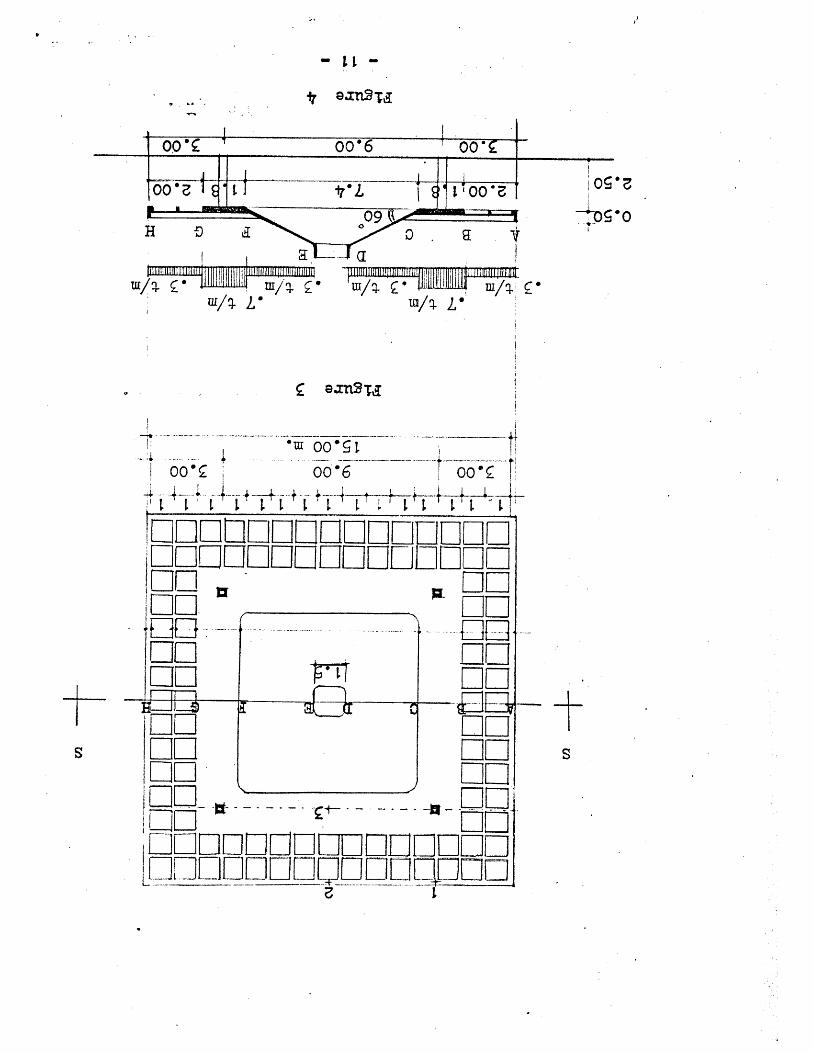
- A folded plate structure, with the horizontal plate
ABC and FGH forming the peripheral low area, and the
inclined plate CD and EF forming the pyramidal major space.
( As seen in section on page 11 ).
- Parts AB and GH form a waffle system, of 1 meter (3feet)
grid, with a depth of 25 centimeters ( 10 inches ).
- Parts BC and FG are a solid slab, of 1.80 meter ( 6 feet )
in width, and 25 centimeters in depth( 10 inches ).
- The structure is supported on four columns, located
at a set-back of 80 centimeters,( 2 feet 10 inches ), from
the four corners of the pyramidal roof.
Structural behaviour :
The folded plate action will occur, as the pyramidal
slab CD will act as a deep beam, to resist the inclined
force Fi; the horizontal slab ABC will act as a tie ring
to resist the horizontal force Ph.
Both ABC and CD, as a folded plate will prevent the move-
ment of point C.in space. ( Figure 20 , page 20 )
Load distribution :
Assumptions of load distribution between the low horizontal
- 7 -

area and the high one, have been calculated in previous' studies
to determine the behaviour of the structure under different
loading conditions.
The final load distribution is calculated in proportion to
the deflections at points of maximum moments.
The horizontal slab iBC is directly supported on the columns,
calculations of the deflections at points 1 ,2 and 3, are
made to determine the load distribution between parts AB
and BC. ( diagram 3 page 11 ).
Beam A will transfer the load it receives from part AB,
to the columns, through the three cantilevers running
over the column, and carrying beam A itself,.( diagram 13
page 18 ).
It is assumed here, that the solid slab ( flat beam ) BC,
will carry 35% of it's own weight, plus the load it
receives from part AB. This load is transferd directly
to the columns. At the same time, part BC will resist
the twisting moments of the cantilevers, hence reducing
the negative moments at the edge C.
The positive moments between the columns, occuring at part
BC due to 35% of the load, previously mentioned, will be
reduced by the over-hangs at both sides .( figure 15 on
page 18 ).
The remaining 65% of the load from part ABC, plus the
- 8 -

vertical component of load from the pyramidal roof, will
form reaction R at point 0; this force R will be resisted
by the folded plate action of ABOand CD. ( diagram 20 on
page 20 )
The pyramidal roof slab has been designed, assuming that
it is fixed at the base and two sides, with the high edge
simply supported. The coefficient of load distribution
has been obtained from the American Reinforced Concrete
Codes.
The area of the cross-section of the column has been
increased, to allow for a drainage pipe, with a diameter
of 10 centimeters (-4 inches ).
A simple rectangular foundation is designed to function
in poor soil conditions.
- 9 -
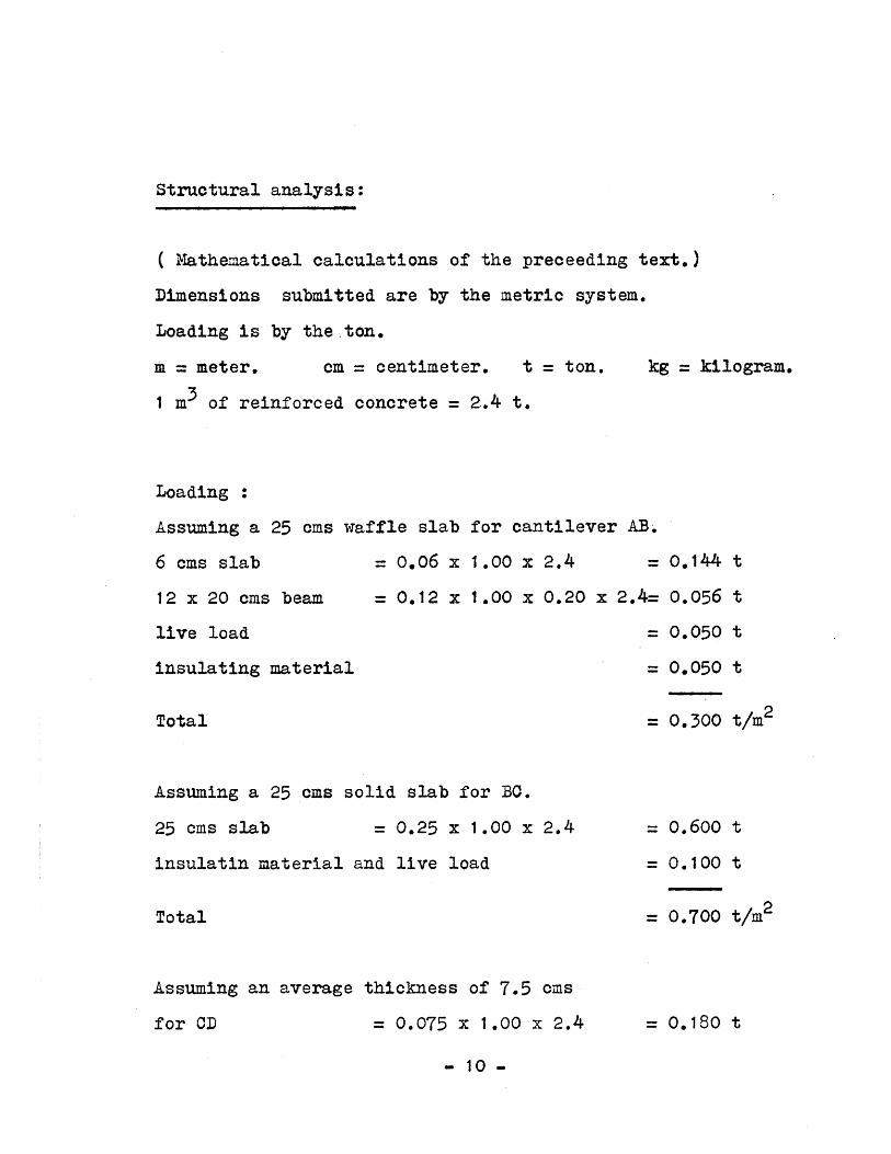
Structural analysis:
( Mathematical calculations of the preceeding text.)
Dimensions submitted are by the metric system.
Loading is by the ton.
m = meter, cm = centimeter. t = ton. kg = kilogram.
1 m3 of reinforced concrete = 2.4 t.
Loading :
Assuming a 25 cms w
6 cms slab
12 x 20 cms beam
live load
insulating material
affle slab for cantilever AB.
= 0.06 x 1.00 x 2.4 =
= 0.12 x 1.00 x 0.20 x 2.4=
Total
Assuming a 25 cms solid slab for BC.
25 cms slab = 0.25 x 1.00 x 2.4
insulatin material and live load
Total
Assuming an average thickness of 7.5 cms
for OD = 0.075 x 1.00 x 2.4
= 0.600 t
= 0.100 t
= 0.700 t/m2
= 0.180 t
- 10 -
0.144
0.056
0.050
0.050
0.300
t
t
t
t
t/m 2
009 00*6 00
H 7D a
OO~~~ *0 Ioo
F2W-- -- "
ID
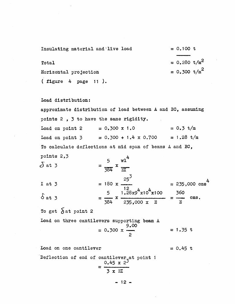
Insulating material and -live load
Total
Horizontal pro Jection
= 0.280 t/m2
= 0.300 t/m 2
( figure 4 page 11 ).
Load distribution:
approximate distribution of load between A and BC, assuming
points 2 , 3 to have the same rigidity.
Load on point 2
Load on point 3
= 0.300 x 1.0
= 0.300 + 1.4 x 0.700
= 0.3 t/m
= 1.28 t/m
To calculate deflections at mid span of beams A and BC,
points 2,3
j at 3
I at 3
S at 3
5 wl4= x
3TW E3
25= 180 x -..
12 4 45 1.28x9 x10 x100= x
384 235,000 x E
4= 235,000 ems
360= Oms.
E
To get Sat point 2
Load on three cantilevers supporting beam A9.00
0.300 x -2
Load on one cantilever
= 1.35 t
= 0.45 t
Deflection of end of cantilever at point 10.45 x 2
3 x EI
- 12 -
= 0. 100 t

I cantilever
at 1
I at 2
gat 2
( figure page
= 15 x 25312 4
0.45 x 23 x 10 x 100
3 x 19,60025 x 253
12
61 0.3x9 x10 X1100= --E+
)32,700 x E
= 19,600 cms4
61
E
= 32,700
660E
Approximate distribution of load between A & BO
Beam A360
= (360+660) X 0.3 x 2.00 = 0.21 t/m
Assuming that beam BC will gain more rigidity , being
connected to rigid beam CD; then beam A will carry less load.
= 0.15 t/m
Approximate distribution of load between BO & CD, assuming
beam BC will carry 35% of the load, while beam CD will
carry 65% of the load.
Load on beam BC = 0.35(0.7x1.8+0.3x2-0.15)= 0.60 t/m
Load on Od from cantilever roof = 0.65 x 1.71 = 1.11 t/m
Assuming distributed load on beam Bc to be triangular
0.60 x 2
1,.8= 0.66 t/m
Design of different parts:
1- Design of cantilever slab: ( figures 2 page 14 )
Mx.x =0.3x2x2.8+0.7x 1.8
-0.15x4.8-0.66x-----3
=1.68+1.15-0.72-0.71 = 1.4 mt
- 13 -
OMS
4cms
Oms.
Pmax

1-. Design of cantilever slab
Deflections at 3&2N
Figure 5
1.-80 - 2.00
.7%m.3t/M
0 Y3 280 .00 2.00 j
XI
Load distribution
Figure 6
Y,
.7 t/m.3t/m
66t .151.802.001
Jd Y
6mt
Figure 7
S.F.D.
.21t
Figure 8.1 5t
.45t
- 14 -
t
1 .11t

= 1 .8x0.7+0.6-0.15-0.6
Design of section x-x
140000d =0.3v 100,-
t chosen 25 cms As
Chosen 7 4 3/8 "
Check of shear
Shear,
1400001250x23
1110100x23x0.87
22=0.3x-2--0. 15x2
= 0.6-0.15
= 1.11 t
= 11.2 cms
=4.85 cms2
= 4.97 cms 2
= 0.555 Kg/cms2
= 0.30 mt= 0.45 t
Design of section y-y
1,/ 30000d =0.3\ V - = 15 cms.
t chosen 25 cms.
300001250x23
Chosen 3 # 5/16
or 2 3/8
Check of shear450
12x23x0.87
= 1 .04 cms2
= 1.47 cms2
=1 .42 ms 2
= 1.88 Kg/cms2
2- Design of beam A: ( Figure s , page 16 )
- 0.15x22
2
= 1.125x4.5- 0.15x7.5 22
= 0.30 tm.
=0.7 tm
- 15 -
Shearx-x
M-ve

"2-5 Design of beam A.
U ~ T- r 1-L 1 -i E}T HM1'If if l1 Hh IDDeflection at 1 -. - 3.00
.19.0 , 3.00
Figure 9
TTITTTTT T ", (TTTTTTTTI-TTTTTYTTTTTTTT
L. Distribution 33.00 9.00 m1 .125t
2.0 t1 1 -- 7.00 m
.375t
Figure
0. Otm
-43.00
1 125t1 It 2.00.
.375t
10
o 30tm
0.70tm
Figure 11
Figure 12
- 16 -
B.M.D *
0.
S.P.D.
45t
0,0.675t
= 16cms.d = 0.3\ 7_0.0025
t chosen 25 cms
AS = 700001250x22
Chosen 2 1/2"
= 2.55 ms
= 2.54 cms2
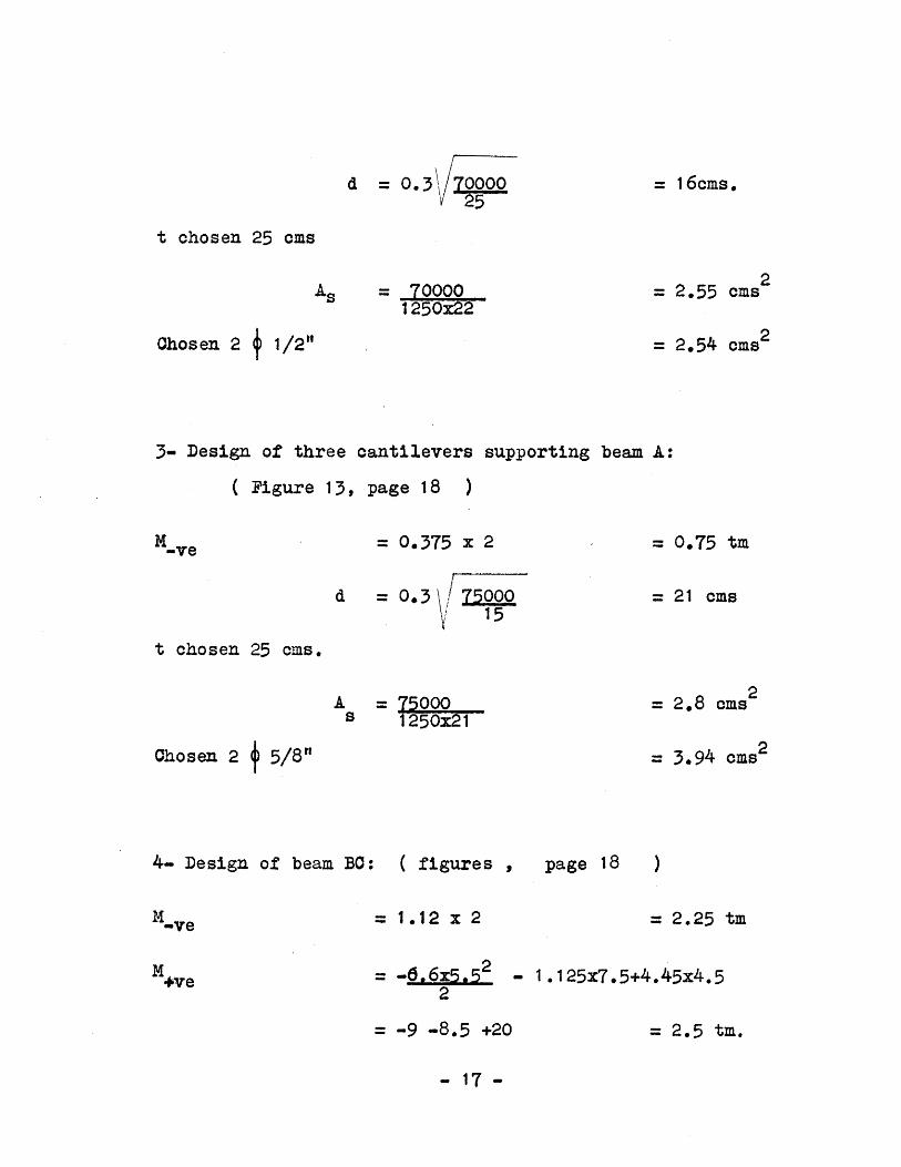
3- Design of three cantilevers supporting beam A:
( Figure 13, page 18 )
Mve = 0.375 x 2 = 0.75 tm
= 21 emsd =0.3 15
t chosen 25 cms.
A = 75000S 1250x21
= 2.8 cms2
= 3.94 ems2Chosen 2 5/8"
4- Design of beam BC: ( figures , page 18 )
M-ve = 1.12 x 2 =2.25 tm
M4Ye = -6.6x5.52 - 1.125x7.5+4.45x4.52
= -9 -8.5 +20 = 2.5 tm.
- 17 -

3- Design of the thre cantilevers supporting beam A.
?.000 1 9.00m
Figure 13
4- Design of beam BO.
1.*1
L. Distribution
52%t 0.6 t/m
4.425t 4.425t2.00 1 9.00 20
Figure 14
B.M.D.
2.5mt
Figure 15
1
1.125t 1.725t2.7t,
Figure 16
- 18 -
O. 75t 0.375t
2.00
1 125t
2. 25mt 25mt
2.7t
_

d = 0.3\ 250000\V' 180
t chosen 25 cms.
A =- 250000s 1250x21
= 9.5 ems2
Chosen 8 0 1/2"
5- Design of pyramidal roof : ( figure 19 page 20 )
= 0.125 x(1.5 +7.4)2
= 0.251.*6752
= 2x0.210
= 5x0.210
= 5x1.11
= 2x1.11
= 0.250+0.420+2.475
= 0.470+2.220
x = 0.250 t
= 0.210 t
= 0.420 t
= 0.470 t
= 2.475 t
= 2.220 t
= 3.145 t
= 2.690 t
6- Design of CD, acting as a deep beam to resist Fi:
( Figure 20, page 20 )
- 19 -
w'i1
w'2
w i
W'h2
vi
Vh
Fi
Fh
= 11.3 ems

4.54m
1 .5m
3.35m
... 7.4 m .
5- &-,-9..oreD6sign. of,-pyraidal roof.0
Figure 17 Figure 18
.145t
Th=2. 690t
R=1.11t
6- Design of CD, Figure 19 Figure 20
1.80mI
7.40m
1 .80m
7- Design of tie beam BC.- 20 -
4.5m
4-
Figure 21
7.4 m 4
9125t
2.475t
.11 it
.
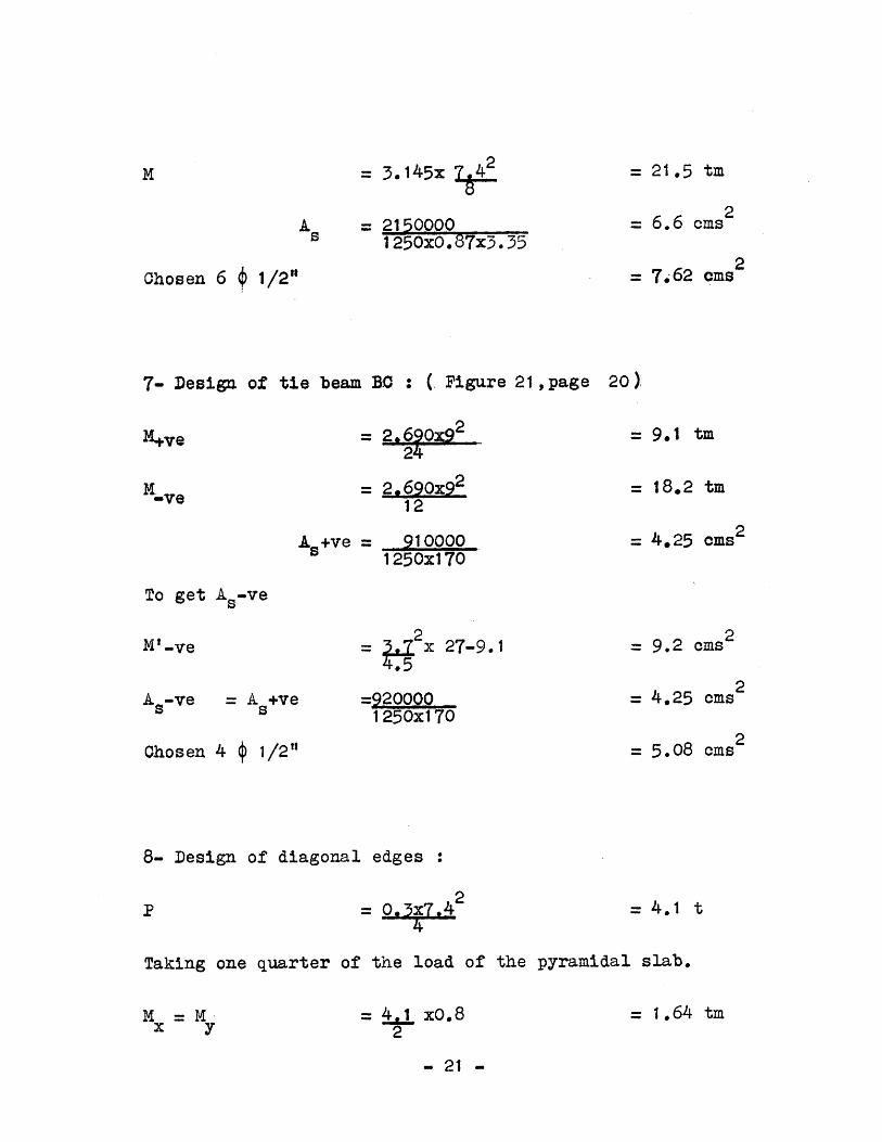
M = 3.145X 2
A = 2150000s 1250x0.87x3.35
Chosen 6 1/2"
= 21.5 tm
= 6.6 ems2
= 7.62 ems2
7- Design of tie beam BO : ( Figure 21 ,page 20 )
= 2.6Ox92
12
As+ve = 9100001250x170
=9.1 ti
= 18.2 tm
= 4.25 ciMs 2
To get A. ve
2= x 27-9.1
As-ve = A +vea s
=9200001250x170
Chosen 4 4 1/2"
8- Design of diagonal edges :
2 0.3x7.4 2
= 9.2 ems2
= 4.25 cms2
= 5.08 ms
= 4.1 t
Taking one quarter of the load of the pyramidal slab.
= 1.64 tm= 41 xO.82
- 21 -
-ve
M' -ve
M =Mx 1
= 1640001250x22
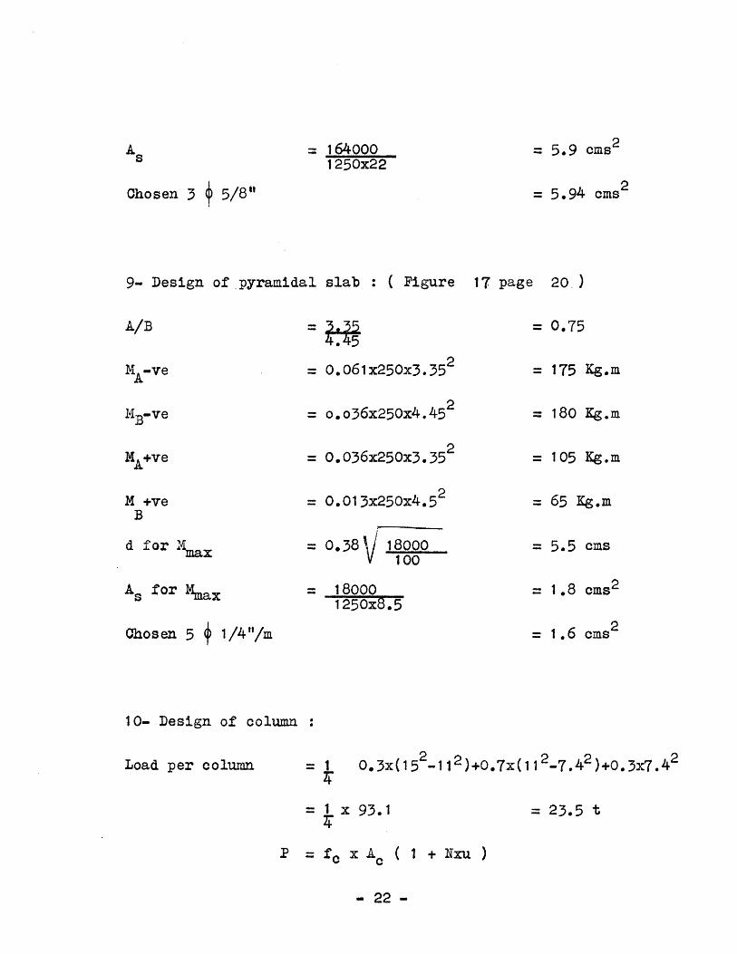
Chosen 3 5/8"
= 5.9 cms 2
= 5.94 cms 2
9- Design of pyramidal slab : ( Figure 17 page 20 )
A/B = 0.75
MA-ve
MB-ve
"A+ve
M +veB
d for vmax
As for Mmax
= 0.061x250x3.35 2
= o.o36x250x4.452
= 0.036x250x3.35 2
= 0.013x250x4.52
=0.38 \/18000V 1 00
= 180001250x8.5
Ohosen 5 j 1/4"1/m
= 175 Kg.m
= 180 Kg.m
= 105 Kg.m
=65 Kg.m
= 5.5 cms
= 1.8 cms2
= 1.6 ems2
10- Design of column :
Load per column = 1 0.3x(152. 112 )+0.7x(1 12 _7.4 2 )+0.3x7.42
=1 x 93.1
P = fo x Ac ( 1 + Nxu )
- 22 -
= 23.5 t
A s

23500 = 45x Ac(1+15x0.008)
= 425 cms2
= 900 cms 2Chosen 30 x 30 cms
To allow for a drainage pipe of 10 cms ( 4 " ) diameter.
= 435x0.004 = 1.74 cms 2
Chosen 4 4 3/8 "
11- Design of foundation:
Net load on soil
fall.
= 24.00 t
= 0.8 Kg/ cms2
i- Design of plane concrete :
A S24 00
Chosen
= 3.00 m2
180 x 180 x 40 cms depth
ii- Design of reinforced concrete footing :
Dimensions: 100 x 100 x 30 oms depth
= 24
2= 24 x1.02
2
= 24 tm
= 1.5 tm
- 23 -
Ac
A5
f
M
=2350045
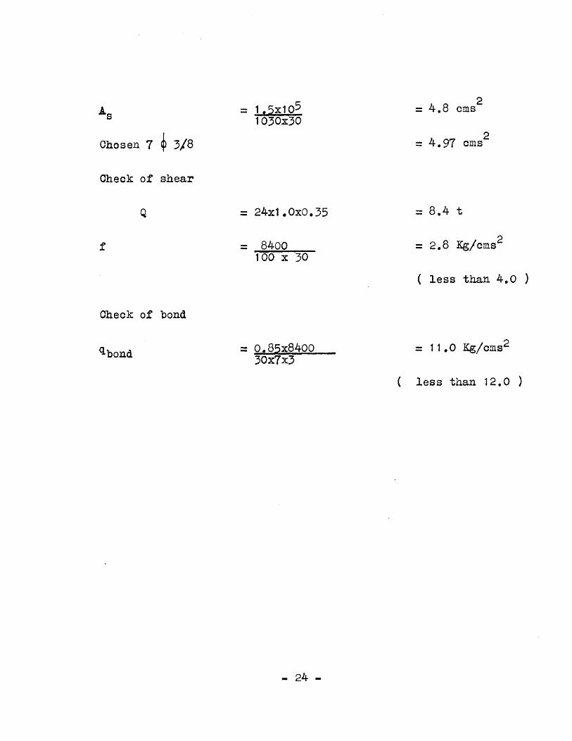
= 1.5x10 5
1030x30
Chosen 7 $ 3/8
Check of shear
= 24x1.OxO.35
= 8400100 x 30
= 4.8 cms
= 4.97 2ms2
= 8.4 t
= 2.8 Kg/cms 2
( less than 4.0 )
Check of bond
= 0.85x840030x7x3
= 11.0 Kg/cms2
( less than 12.0 )
- 24 -
Q
qbond

2. QUALITY OF SPACES
The quality of the low horizontal space is different from
that of the high one, since they accomodate different activities.
The pyramidal high space - of 9 x 9 meters ( 30 x 30 feet ),
is designed to house a major group activity, a class room
of 30 - 40 students. The introduction of matural top light
will allow the continuity of the low , and the high
surfaces, a major point affecting the design.
The horizontal low peripheral space - of three meters ( 10
feet ) width - is designed on a one meter ( 3 feet ) grid;
this will allow for the subdivision of the spaceto house
the minor activities, related to the major space, such
as circulation, storage, offices, lavatory accomodations.
The low horizontal flat area, combines the pyramidal roof
and the grid system, in a harmonious transition of surfaces.
3- ADMITTANCE OF LIGHT
Natural light :
Top light : day light is admitted in the structure, through
a plastic dome, 1.5 x 1.5 meters ( 5 x 5 feet ), to diffuse
the direct sun rays ; below it, is an aluminum grid, to
provide uniform intensity of light , over the student's
desks. - 25 -

Side light : will be admitted only from two directions,
perpendicular to the plain of the black-board
Artificial light:
The artificial light is integrated within the structure,
and is located in the same place where natural light is
admitted, to maintain the same qualities of the space.
The light will fall indirectly, either through the
aluminum grid, or reflected from the pyramidal slab,
as seen in section. The structure allowS the use of
1.2 and 0.6 meter ( 4 feet and 2 feet ) , fluorescent
lamps.
Number of lamps needed
21w
( h, 1 and w are the dimensions of the room.)10 x 60 1
2x30x30 3
f =0.3348
D =fg F... where g = 0.60A
50 = 0.3348 x (0.60) F1200
F1 = 225,000 lumens
14 lamps, of 200 watts each, will provide the tequired
intensity, of 50 lumens per foot square, on the student's
desks. s 26

4- VENTILATION
The natural flow of air is organized, to ventilate the
space. The pyramidal roof will act as a hood, to collect
the hot air, full of carbon dioxide, to be sucked out
through the ventilating openings, in the uppermost central
part. Cold fresh air, is let into the space either
through the side windows, or through controlled louvers
at the floor level. This chimney action will speed up
the air flow; also a fan could be used to control it,
and to eliminate any undesirable thermal conditions, created
by the plastic dome. No heating systems are required,
on the contrary, heat insulation is needed.
5- ACOUSTICS
No sound treatment is needed, because of the small dimensions
of the room. Reverberation time is calculated for the
class room, when empty and when full, in both cases, it
is between the allowable limits of 0.6 and 1.4 seconds.0.49 V
Reverberation time =a
Volume of room = 11,160 cubic foot
Surfaces:
Brick walls = 615 x 0.04 = 24.6
- 27 -

Reinforced concrete = 1264 x 0.3 = 379.?
Glass ='90 x 0.2 = 18.0
Wood = 270 x 0.1 = 27.0
Cement floors = 1170 x 0.02 = 23.4
472.2
Chairs and tqbles = 150 x 0.22 = 33
Chairs, tables and students = 150 x 0.7 = 105
Class room empty = 505.2
Class room full = 577.2
Reverberation time when class room is empty0.49 x 11160 = 1.08 see
50502
Reverberation time when class room is full0.49 x 11160 = 0.98 sec
577.2
Double walls with 15 centimeters ( 6 inches ) , clearance,
are used between the lavatory accomodations and the class
rooms, to prevent any sound transmission.
6- THERAL INSULATION
Heat insulation will be the main concern, since the weather
is generally warm and sunny in Egypt most of the year round,
with rain occuring for two to three months during the winter,
and only in the northern part of the country.
- 28 -

Light weight aggregate, sand, white cement and gypsum are
used in different percentages, according to the climatic
conditions; more cement is to be used in wet weather,
while more gypsum is to be used in dry weather. Both
white cement and gypsum will form good reflecting surfaces,
they will increase the amount of reflected light, and will
decrease the amount of heat absorbed by the roof. This
layer of light-weight concrete, will act as a thermal
insulator, that protects the underlying reinforced concrete,
from extremes of temperature, thus prevent cracking and
leakage of water in cases of rain, also it provides a
sloping surface for water drainage.
7- SUBDIVISION OF SPACE
Partitioning : The low peripheral horizontal area, is designed
on a one-meter grid. The beams to the interior measure
12.5 centimeters, to receive a 12 centimeter ( 5 inch ),
half-brick wall. The beams to the exterior, measure 27 cms,
to receive a 25 centimeter ( 10 inch ) one-brick wall, or
a 15 centimeter cavity-brick wall.
The one meter module of partitioning , is a reasonable
dimension for standard windows, doors, W.C.spacing, etc.
- 29 -

8- CONSTRUCTION
Form work :
Durable materials are selected for the forms, to resist
the wear and tear. Forms are to be erected, steel placed
in position, concrete poured then left to dry, then the
forms are to be dismounted and reused. This will speed
the erection cycle, and will cut down the cost.
i- Waffle slab : Metal pans, 1 x 1 meter ( 3 x 3 foot ),
20 centimeters deep ( 8 inches ), are placed on wooden
joists, leaving in-between a cavity, to form wedged
beams of 12.5 centimeters ( 5 inches ), at the bottom,
and 15 centimeters (6 inches ) at the top. This will
facilitate pulling out of the metal pans after the setting
of the reinforced concrete.
ii- Pyramidal roof : Consists of four half-cylinder surfaces,
and four traperoidal plate, all made of 3 x 3/4 inch hard
wood boards, grooved and tongued, leaving a V shaped
chanel between the boards.
iii- Columns: Forms consist of square wooden shafts,
30 x 30 centimeters ( 12 x 12 inches )and 240 centimeters
( 8 feet ) in height, with a 4 inch drainage pipe in the
center.
iv- Footing : Simple rectangular wooden plated at four
sides, and the plane concrete foundation at the bottom,
- 30 -

will form a casing for the footing.
Flooring :
The floor consists of three layers, ( from top to bottom ):
1- 5 centimeter (2 inch ) layer of cement, sand and fine
aggregates. A grid pattern , 1 x 1 meter ( 3 x 3 foot ),
of grooves is made to prevent the cracking of cement.
11- 2 centimeter Damp-Proof Course of asphalt.
111- 15 - 20 centimeter ( 6 - 8 inch ) plane concrete, of
cement, sand and aggregates.
CONCLUSION
A Reinforced Concrete structural system, can be developed,
to define an architectural expression, of enclosing diff-
erent spaces for useful occupancy.
The new techniques of construction, and mass production
systems, can be utilised to reduce the essential costs,
and to facilitate the erection processes.
This study deals with new possibilities, that have broad
applications, in the building industry in Egypt.
- 31 -

0zLL
xen
OLL
J
z

___________ - ~ '.- ..JIJL.................J~ L..........................J L................. liii _________ .J[I I
PLAN OF THE
U
Lr LL _ El
IF 11
UNIT REINFORCED CONCRETE MODULAR ROOF UNITMSTER OF ACHITECTRETHES SCALE :92.SHIARKI BANIM RFAAT JU LY 962.
/
111:111:1 E
U
A --

REINFORCED CONCRETE MODULAR ROOF UNITMASTER OF ARCHITECTURE THESIS SCALE I * 25.
SHAFIK IBRAHIM RIFAAT JULY 19 62.
77
-------------- - -------------- ------
------------------------- -----------------------
ELEVATION.
SECTION A-A-.

2 $1 3/8 14 3/8"14 3/. -
2 1 3/8" 2$ 3/8"
24 /2" 1# 3/' 4 3/8" 2# 1/2" #/4" s2 I., 2 # I/" S#3/'" 14 3/2" 24 I2"
SECTION 3-3-
24 3/8"a0 318 -- -
24 1/2" ___ 4_ E 1/2" -
7# 3/87m / 44%/4j 7 3/"/m
24 3/a" 4# /2" 743/8"/. 44 l/4"/ 4 I/4"/m - 7 3/8
. EW,2#11 I/2 43/8" I/2"at 2#
4 l/ m 243/8 2 3/ 8"
5'* 3/d,WI
601/2" 1#3/8" 241/2"
.M.D. AT SECTION 2.2.
SEC TI ON 2-2-
2$y /2" 76 3/8" m 1,/2" 2$ 3/8N
- _- 4"
8.M.D. AT SECTION 1-1.
REINFORCED CONCRETE MODULAR ROOFMASTER OF ARCHITECTURE THESIS SCALE
SHAFIK IBRAHIM RIFAAT JULY
2 4 I/" 2 4 3/8" 24 I/e 113/8" 2,3/8"- #3/8'
SECTION I-I.UNITS: 251962
SECTION A-A.
B.M.D. AT SECTION 3-3.
O 6 1/2"
20 6/2"

t4
REINFORCED CONCRETE MODULAR ROOF UNITMASTER OF ARCHITECTURE THESIS SCALE I : 25
SHAFIK IBRAHIM RIFAAT JULY 1 9 62
1 LV 2-at 20
L- |n
\\ U 3/8" //
TIE BEAM ACTION TO RESIST HORIZONTAL FORCE F h
R=A,
FOLDED.PLATE ACTION TO RESIST FORCE R.
PLAN OF CEILING
2

3-+ - -- -
REINFORCED CONCRETE MODULAR ROOF UNITMASTER OF ARCHITECTURE THESIS SCALE 1 =25
SHAFfk IBRAHIM RIFAAT JULY 1962
- - - - - - - -2 3 / -
A~~~ -- -- -i --t - 3- ---
$2 1/
- - -. .. 2 - 1/2
- 4 3/E
- 4-
t 2 t318
70~ 4 m
_ - 7 3/ m
1 4 3/8 - - - 3/q"
14
14/2
- 2
2
2
PLAN OF ROO F

( i
I N~ '5 ii p
.27-"
1Q,.'
- S TL K I
- 0 EN-Al
AlA -R OW
PLAN
REINFORCED CONCRETE MODULAR ROOF UNITMASTER OF ARCHITECTURE THESIS SCALE I . 25
SHAFIK IBRAHIM RIFAAT JULY 1962
5
ELEVATION

Dl -
SECTION A..A.
REINFORCED CONCRETE MODULAR ROOF UNIT
MASTER OF ARCI4ITECTURE THESIS
SHAFIK IBRAHIM RIFAAT JULY I 9 62
PLAN
A A
SCALE 1 25.

PLAN REINFORCED CONCRETE MODULAR ROOF UNIT.MASTER OF ARCHITECTURE THESIS. SCALE I : 25.
SHAFlK IBRAHIM R IFAAT. JULY I 9 6 2.