sf1400 - series manuals/… · · 2014-03-12manual manufactured by: rottler manufacturing company...
TRANSCRIPT

October 14, 2002
SF1400 - SERIES SURFACING MACHINE
MACHINE SERIAL NUMBER
___________________________
OPERATIONS AND MAINTENANCE MANUAL
MANUFACTURED BY:
ROTTLER MANUFACTURING COMPANY 8029 South 200th Street Kent Washington 98032
USA
Phone: (253) 872-7050 Fax: (253) 395-0230
Website: http://www.rottlermfg.com
NOTE: WHEN ORDERING REPLACEMENT PARTS, PLEASE GIVE THE MODEL AND SERIAL NUMBER.
ORDER BY PART NUMBER. THERE IS A MINIMUM ORDER OF $25.00


Table of Contents Page 1 SF1400 Manual
Chapter 1 Introduction:........................................................................................................................... 1-1Description: ......................................................................................................................................... 1-1Limited Warranty: ................................................................................................................................ 1-1Safety Information:.............................................................................................................................. 1-1Electrical Power: ................................................................................................................................. 1-2Machine Operator: .............................................................................................................................. 1-2Emergency Procedure: ....................................................................................................................... 1-2Machine Installation: ........................................................................................................................... 1-4
Location: ....................................................................................................................................... 1-4Unpacking:.................................................................................................................................... 1-4Lifting: ........................................................................................................................................... 1-5Leveling: ....................................................................................................................................... 1-5Power Supply: .............................................................................................................................. 1-6
Chapter 2 Control Definitions: ............................................................................................................... 2-1Vertical Rapid:..................................................................................................................................... 2-1Horizontal Rapid:................................................................................................................................. 2-1Spindle Start/Stop: .............................................................................................................................. 2-1Feed Start/Stop: .................................................................................................................................. 2-1Auto/Manual: ....................................................................................................................................... 2-1
Preset / Variable: .......................................................................................................................... 2-2Variable Spindle RPM: ................................................................................................................. 2-2Variable Horizontal Speed:........................................................................................................... 2-2Vertical Manual Knob: .................................................................................................................. 2-2
Chapter 3 Operating Instructions: ......................................................................................................... 3-1Mounting a Cylinder Head on the Universal fixture: ........................................................................... 3-2Mounting a V Block on the Universal Fixture:..................................................................................... 3-6Manual Operation: .............................................................................................................................. 3-9Automatic Operation: .......................................................................................................................... 3-9Cutting Inserts ................................................................................................................................... 3-13
Carbide (uncoated) :................................................................................................................... 3-13CBN - Cubic Boron Nitride: ........................................................................................................ 3-13PCD - Polycrystalline Diamond: ................................................................................................. 3-13Coated Carbide: ......................................................................................................................... 3-13Composite Ceramic: ................................................................................................................... 3-13
Chapter 4 Maintenance: .......................................................................................................................... 4-1Oiler:.................................................................................................................................................... 4-1Dial Indicator Setting:.......................................................................................................................... 4-2

Introduction / Safety / Installation 1-1 SF1400 Manual
Chapter 1 Introduction:This manual is divided into sections as listed in the table of contents.
It is required that the new user of the SF1400 read this manual, in particular the sections concerningsafety, before operating the machine.
Description:The model SF1400 surfacing machine is a precision, high speed surfacing unit.The model SF1400 can be equipped with tooling and accessories for surfacing most American passengercar and truck, inline, 90 and 60 degree V-type blocks as well as cylinder heads.SF1400 machines may be readily tooled to resurface a wide variety of engines, including European andAsian models, as well as perform various other surfacing operations.
This machine is designed for two purposes:
1. The alignment of the deck surface to the pan rails and main bearing locations, as have been done inthe original factory surfacing.
2. A considerable savings in surfacing time and operator involvement as a result of fast block clamping,and convenient controls.
Change over or resetting time required to set up V-type or in-line engines is a minimum, making thismachine highly suited to the jobber shop where engines cannot be run through, in model lots.All feeds and rapid travels are power operated and controlled from the conveniently located control panel.Power required is 230 volt, single phase. This provides power to the variable speed AC motor controller,the horizontal S.C.R. drive, and various relays and solenoid valves that actuate mechanical controls onthe machine to engage feeds and travels. See electrical section for proper electrical connection.
Limited Warranty:Rottler Manufacturing Company Model SF1400 parts and equipment is warranted as to materials andworkmanship. This limited warranty remains in effect for one year from the date of delivery, provided themachine is owned and operated by the original purchaser and is operated and maintained as per theinstructions in the manual.
Tools proven to be defective within the warranty period will be repaired or replaced at the factory’s option.
We accept no responsibility for defects caused by external damage, wear, abuse, or misuse, nor do weaccept any obligation to provide compensation for direct or indirect costs in connection with casescovered by the warranty.
Freight charges on warranty items (non-air shipment only) will be paid by Rottler Manufacturing for aperiod of 60 days only from the date of installation or set-up by a qualified service technician or salesrepresentative.
Freight charges after the 60 day period are the customer’s responsibility.
Safety Information:
CAUTION: This machine is capable of causing severe bodily injury!
The operator of the SF1400 should be a skilled machinist craftsman who is well versed in the caution,care, and knowledge required to safely operate metal cutting tools. Eye protection must be worn at alltimes by the operator and all other personnel in the area of the machine.
The operator should be extremely cautious when working around the cutting tool area.

Introduction / Safety / Installation 1-2 SF1400 Manual
When boring the machine is capable of throwing metal chips over 10- feet from the cutting area. Alwaysuse the guards.
The SF1400 operates under computerized control and, as is all computerized equipment, is susceptibleto extraneous electrical impulses internally for externally produced. The machine may make moves out ofthe operator control at any time. The operator should work in and around the machine with caution at alltimes.
The operator and nearby personnel should be familiar with the location and operation of the EmergencyStop Button.
Electrical Power:Make sure all electrical equipment has the proper overload protection. The SF1400 should have a fullyisolated power supply to prevent damage and uncontrolled movement of the machine. If the SF1400 ison the same power lines that are running to other electrical equipment (grinders, welders, and other ACmotors) electrical noise can be induced into the SF1400 electrical system. Electrical noise can cause thecontroller to see false signals to move. Not supplying a fully isolated supply to the machine may voidfactory warranty. Refer to the Power supply section later in this chapter for voltage and amperagerequirements of the SF1400.
Machine Operator:Operator of this surfacing machine should be a skilled machinist craftsman who is well versed in thecaution, care, and knowledge required to safely operate a metal cutting tool.
If the operator is not a skilled machinist, the operator must pay strict attention to the operating procedureoutlined in this manual, and must get instruction from a qualified machinist in both the productive and safeoperation of this surfacing machine.
Rottler surfacing equipment has the following areas of exposed moving parts, that you must train yourselfto respect and stay away from when they are in motion:
1. Cutting Tool Area: Any operation involving hands in the cutter head area, such as inspection oralignment of the cutterhead or cutting tools requires the power be turned off to the machine.
2. Surfacing: Eye protection must be worn: during this operation and hands must be keptcompletely away from cutter head. All chip guards must be kept in their normal operatingpositions.
3. Operator panel controls: Learn to identify and independently operate these controls by habit,while developing an awareness of keeping fingers and hands clear of moving machinery.
4. Work Loading and Unloading: Carefully develop handling methods of loading and unloadingwork pieces, so that no injury can result if hoist equipment or lift connection should fail.Periodically Check lift components for damage that may cause failure of Block Handler Assembly.Lifting eye can eventually fail if the eye is reset in line with the 502-1-80 lift channel. Eye mustbe at right angle to this channel.
5. Machine maintenance: Any machine adjustment, maintenance or parts replacement absolutelyrequires a complete power disconnect to the machine. THIS IS AN ABSOLUTE RULE.
6. Emergency Procedure:Assuming one of the following has occurred: Vertical height set completely off or work piece is notclamped, these mistakes will become obvious the minute the cut starts
PRESS THE EMERGENCY STOP BUTTON (on the front control panel) IMMEDIATELY!
Find out what the problem is; return the spindle to its up position without causing more damage. Torestart the machine, turn the Emergency Stop Button CW until the button pops out. Make sure the button

Introduction / Safety / Installation 1-3 SF1400 Manual
has been depressed for at least 1 ½ minutes or the drives will not have time to reset and they will notfunction.
Be alert to quickly stop the machine in the event of a serious disruption of the surfacing process.
“REMEMBER” metal cutting tools have the speed and torque to severely injure any part of thehuman body exposed to them.

Introduction / Safety / Installation 1-4 SF1400 Manual
Machine Installation:
Location:The productivity of this machine will depend a great deal on it’s proper initial installation, particularly themeans by which cylinder blocks/heads are lifted into the machine as well as the material handling to andfrom other operations in your shop.
The proper loading arrangement and location for your SF1400 machine is extremely important.
A slow travel (6 to 10 feet / min.) power hoist, operated from either a bridge crane or a jib cranearrangement works very well. A 1000-lb. hoist is generally adequate for lifting the engine block. An airhoist with speed control makes an ideal method for fast, convenient loading.
If some production surfacing with this machine is anticipated, and the cylinder blocks/heads are notdirectly loaded and unloaded from a conveyor, we recommend considerable attention be given to thecrane so that it covers an adequate area to allow the operator to back up and remove cylinderblocks/heads without cluttering up his own area. If two machines are to be operated by one operator, werecommend that the open faces be placed at right angles to each other, with the machines about threefeet apart.
Unpacking:Use care in removing the crate from the SF1400 machine, do not use force on any part of the machine.
Rust inhibitor is applied to the machine at the time of shipment, any of this inhibitor left on the machinewill result in considerable collecting of cast iron dirt.

Introduction / Safety / Installation 1-5 SF1400 Manual
Lifting:
CAUTION: Do not lift the SF1400 by the Horizontal table. It will cause sever damage to the Linear Waybearings.
Insert a 3 foot by 1 inch diameter solid steal or cast iron rod through the hole in either the left or right handside of the lower main base as shown below.
Using a forklift, with the forks one fork on either side of the bar, lift until the center of the machine is atleast 4 inches off the ground. Slide a 4 X 4 under the machine base (front to back) in the middle of thebase. Set the machine down onto the 4 X 4. This will leave enough room on both sides of the 4 X 4 toslide the forks in. At this point you can pick the machine up from the front or the back.
Leveling:There are three leveling locations on the SF1400. One at each end on the outside and one in the rearinside the machine base. You will need to remove a cover to get to this location.
Use a precision level and level the upper table within .0005” per foot in both directions and make sure thatthe machine weight is equally supported at the support points of the base.


Introduction / Safety / Installation 1-6 SF1400 Manual
Power Supply:This machine requires 208 to 240 VAC single phase, 50/60 Hz, (measured between L1 and L2). Currentrequired is 15 amps. When using two legs of a three phase supply the voltage from each leg to groundmust be between 100-120 VAC. Connect per following electrical hook-up instructions. If the voltage isoutside this range the machine will not operate properly and may be damaged.
CAUTION: Do not attempt to attach three phase. The three phase motors receive power from threephase variable frequency invertesr located in the main electrical enclosure. The frequency inverter mustbe single phase powered.
Connect single phase wiring to the three wires coming out of the top of the electrical enclosure. Themachine is not sensitive to neutral/hot leg phasing. Two legs of a 208-240 VAC 3 phase supply can beused.
CAUTION: This machine must be connected to a good earth ground. Connect the earth ground wire tothe terminal with the green grounding wire attached to it, on the terminal strip mounted in the upper rightside of the electrical enclosure.

Control Definition 2-1 SF1400 Manual
Chapter 2 Control Definitions:This chapter is intended to familiarize the operator with the function of all the controls.
Vertical Rapid:This is a three position momentary contact lever. Press, and hold, the lever up and the machine willrapid travel up until the lever is released or a limit switch is hit. Press and hold, the lever down and themachine will rapid travel down until the lever is released or a limit switch is hit. When the lever is notbeing pressed it will return to the center position, which is no movement.
Horizontal Rapid:This is a three position momentary contact lever. Press, and hold, the lever right and the machine willrapid travel right until the lever is released or a limit switch is hit. Press and hold, the lever left and themachine will rapid travel left until the lever is released or a limit switch is hit. When the lever is not beingpressed it will return to the center position, which is no movement.
Spindle Start/Stop:This control has two buttons. Pressing the Green button will turn the spindle on at the set speed andpressing the Red will turn the spindle off.
Feed Start/Stop:This control has two buttons. Pressing the Green button will turn the horizontal feed on at the set rateand pressing the Red will turn the horizontal feed off.
Auto/Manual:This is a two position selector switch. It will select between Automatic and Manual modes of operation.See the Operating Instructions section of this manual for using the Auto and Manual Modes.
RPM Read out

Control Definition 2-2 SF1400 Manual
Preset / Variable:This will select between three preset spindle speeds or the use of the variable Spindle RPM knob when inthe Automatic Mode. The spindle speed options are 600, 900 and 1100 RPMs.
Variable Spindle RPM:This knob is used to set the spindle RPM when the spindle start has been pressed. The RPM isdisplayed on a digital read out to the left of the control. It is mounted on the electrical enclosure.
Variable Horizontal Speed:This knob is used to set the horizontal feed rate.
Vertical Manual Knob:This knob, located to the upper right of the control panel, is used to manually move the vertical position.

Operating Instructions 3-1 SF1400 Manual
Chapter 3 Operating Instructions:Included in this chapter is a general description of how to use the basic machine for surfacing, whether itis a cylinder block, head or other type of job. For details of operating the specific fixtures available for thismachine refer to the Optional Surfacing Fixtures and Tooling section of this manual.

Operating Instructions 3-2 SF1400 Manual
Mounting a Cylinder Head on the Universal fixture:
Locate suitable threaded holes and bolts on one side of the cylinder. Fit the cylinder head to theMounting plate. Level the head as close as possible without using a level. Tighten down the mountingbolts.
Place the Dual Axis level on the head gasket face for precision leveling.
Mounting Plate
Cylinder Head
Dual Axis Level

Operating Instructions 3-3 SF1400 Manual
Loosen the left and right hand clamps on the fixture.
Level the front to back first by turning the fine adjusting Hex screw on the lower right hand side of thefixture. Do not attempt to adjust the level exact at this point.
Left
Right

Operating Instructions 3-4 SF1400 Manual
Loosen the Lock screw on the right hand side of the universal mounting plate.
Adjust the Left Right by turning the eccentric studon on the left end of the universal mounting place.
Once the head is level, tighten the left and right locks back up along with the locking screw on theuniversal mounting plate.
Left Right Lock Screw
Eccentric Studon

Operating Instructions 3-5 SF1400 Manual
Fit the Jack screw and engage under the head to support it during surfacing. Be sure to check the levelwhile fitting the jacking device.
Some people recommend mounting the cylinder head in front of the universal mounting plate as shownbelow. Rottler has tested both methods and determined that the best method is what ever the operator iscomfortable with.

Operating Instructions 3-6 SF1400 Manual
Mounting a V Block on the Universal Fixture:
Remove the Cylinder Head Mounting plate from the universal fixture.
If the two (2) end clamp rings are not in place on the bar, remove the bar and fit the two rings.
Make sure the jacking devices and the T slot studs are in the front and rear T slots of the table betweenthe left and right support parallels.
Rotate the bar so that the flat face is upwards (shown above).
End Clamp Ring
JackingDevices
T Studs
Bar Flat

Operating Instructions 3-7 SF1400 Manual
Lock the left and right end clamps so the bar cannot rotate.
Right Lock
Left Lock

Operating Instructions 3-8 SF1400 Manual
Gently Lower the V block so that the Mains locate on the two edges of the flat. Fit the Studs to the clampRings, then the Clamp Bar to the Studs. Evenly tighten both ends of the Clamp Bar as not to misalign theblock on the bar.
Clamp Bar
Clamp RingStuds
TighteningBolts
Once the block is firmly clamped to the bar, it is ready to be rolled in either direction for surfacing. Makesure to put the jacking devices under the block to support it’s weight.
Jacking Device

Operating Instructions 3-9 SF1400 Manual
Manual Operation:Select the Manual Mode of operation from the front control panel.
This mode is used to move the machine around using the joysticks. If the Spindle is started the Verticaljoystick and the Feed button will not operate. The Horizontal joystick will operate while the Spindle is on.
Automatic Operation:For the following description to work correctly, we are assuming that the Depth Dial indicator has beencalibrated correctly (see the maintenance section of this manual for proper setting description).
Press left travel Joystick, rapid left to the desired starting position. The starting position is just before thecutterhead guard starts to pass over the workpiece. Slide and lock the right limit switch actuator so thatthe limit switchis depressed. The Depth Dial indicator should be over the workpiece at this time. With twofingers on the Horizontal pins, push the depth dial indicator on the guard down until the travel stops.Operate the Up/Down Joystick and jog the workhead down until the depth dial probe just touches theworkpiece.

Operating Instructions 3-10 SF1400 Manual
While still holding the Depth Dial down, slowly rotate the fine feed manual handwheel down until thedesired amount of stock removal is seen on the Depth Dial Indicator.
Select Manual on the control panel.

Operating Instructions 3-11 SF1400 Manual
Dial in the desired Spindle RPM and start the spindle rotation, the light will turn on when the spindle isrotating.
Dial in the desired Feed Rate and start the horizontal feed, the light will turn on when the feed is started.
When the cutter has passed the left end of the workpiece and completed the surfacing, slide and lock thelimit switch actuator so that the limit switch is depressed. This will then cause the spindle to stop,workhead to lift up and the table to return to the right hand limit switch setting.
See limit switch positions and adjustors on the following page.
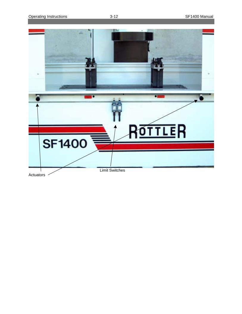
Operating Instructions 3-12 SF1400 Manual
Limit SwitchesActuators

Operating Instructions 3-13 SF1400 Manual
Cutting InsertsRottler offers several different 3/8” I.C. Negative Rake cutting inserts for the SFOE machine. Below is adescription of each.
Carbide (uncoated) :(R8 Round: #6301G)This is an economical general purpose insert.
CBN - Cubic Boron Nitride:(Round: #6303B)(Square: #6301J)These are very high performance inserts used for cutting cast iron. Using the 14 inch diameter cutterheadof the SFOE machine the RPM can be run between 500 and 1250. The lower end of the speed range isused primarily for cutting diesel blocks and heads since they are usually harder.The upper end of the speed range is used primarily for automotive blocks and heads. The optimum RPMfor automotive work is about 950 RPM. This will give tool life resulting in an approximate insert cost perhead of 5 to 15 cents. If a higher RPM is used tool life will be reduced, increasing tool cost per head tobetween 30 and 50 cents.
CBN can be used for cutting aluminum and usually is, when you are cutting a few aluminum headsamong a lot of cast iron heads. When the quantity of aluminum heads is higher it is more economical tochange to an insert designed for aluminum. When cutting aluminum with CBN use some type of lubricant(WD40, Pam, or any type of oil) otherwise the aluminum will build up on the edge of the insert. The toollife of a CBN insert is no greater than a coated carbide insert when machining aluminum so it is muchmore cost effective to use coated carbide when machining quantities of aluminum.
CBN does not cut cylinder heads with pre-combustion chambers. CBN can be used to cut heads withexposed hard seats such as some Cummins heads but a slower RPM should be used and tool life will bereduced. Some shops dress the seats down with a seat and guide machine before surfacing.CBN can be used to cut soft weld material. Set the RPM between 500 and 800.
PCD - Polycrystalline Diamond:(Round: #6303M)This is a very high performance insert used for cutting aluminum. When used on the 14 inch cutter headthe machine can be run at 1000 to 1200 rpm, .005 to .010 deep and produce a very smooth finish.
Coated Carbide:(Round #6303K)This is an economical, high positive rake insert for cutting aluminum. In applications where a highpercentage of the work is aluminum, this insert will surface heads economically, with a smooth finish,without oil, and it is designed for chip removal. Considering the price of the insert and the tool life thecoated carbide insert is roughly 1/10 the cost of a CBN or PCD. When cutting aluminum the spindle RPMcan be run at its maximum speed. Coated carbide can be used to cut cast iron but the RPM must bereduced to between 500 and 1000.
Composite Ceramic:(Square: 6301I)This insert is used to cut the pre-combustion chambers on the Ford / International 6.9, 7.3, and GM 6.2heads. The insert has eight cutting edges. Each edge typically makes three passes at 500 rpm, .004deep, and 7-inches per minute feed rate.

Operating Instructions 3-14 SF1400 Manual
It is critical that the head be mounted in the fixture correctly.
If the head is not mounted this way, the inserts willchip when they contact the sharp edge of the pre-combustion chamber.
Note: There are at least two different materials used in the manufacture of the pre-combustion chambers.Rottler Manufacturing has experimented with only one material. Rottler cannot guarantee cutting allmaterials.
CAUTION: The precombustion chambers in some heads have very loose fits and may come looseduring the machining process resulting in insert damage.
Feed and Speed 1 InsertRPM 1000F.R. 2”/min. 12 rms.RPM 1000F.R. 5”/min. 20 rms.RPM 1000F.R. 10”/min. 30 rms.RPM 1000F.R. 20”/min. 60 rms.RPM 1000F.R. 30”/min. 90 rms.

Maintenance 4-1 SF1400 Manual
Chapter 4 Maintenance:
Oiler:The oiler on the SF1400 is a manual oiler. The operator will need to go to the oiler several times a day tooil the machine. The oiler is located on the rear column of the machine on the right hand side.

head greaser.jpg (2015x2724x24b jpeg)

slides greaser.jpg (2282x2785x24b jpeg)

table-screw greaser.jpg (1802x2531x24b jpeg)

'(6&5,37,21 7<3(2)/8%5,&$17 ,17(59$/
Feed nut - head screwBearing 7306Bearing 7209
Mobil VACTRA oil n°4Castrol Magna CFX 220Esso FEBIS K220Shell TONNA oil T220
Slides
Feed nut - table screw
Bergoline grease RULTEN 900 NGLI 2or other stearate hydroxid litthium grease of high quality
500 working hours; replace every 6 month.
Oil pump
Bergoline grease RULTEN 900 NGLI 2or other stearate hydroxid litthium grease of high quality
500 working hours; replace every 6 month.
4 working hours actuate the pump;refill when necessary.

Maintenance 4-2 SF1400 Manual
Dial Indicator Setting:If chip shield, cutting insert, or dial indicator have been moved, the dial indicator should be reset.
Install a test piece into the SF1400. With surfacing cutter installed into the cutterhead, use the HorizontalJoystick to move the cutterhead until it overlaps the test piece by about ½”.
CAUTION: Turn the power off machine before handling the cutterhead.
Touch off the surface of the test piece by turning the vertical hand feed until the cutting insert just touchesa piece of paper on the test piece when rotated back and forth.
Note: Do not lower the cutterhead directly onto surface, it may chip the cutting insert.
Make a very light cut on your test piece about 1” in. Back out of the cut without adjusting the verticalheight. Press the dial indicator down using two fingers on the horizontal pins until the stop ring isreached.
Turn the indicator dial face so that the “0” is in the 12 o’clock position.
To adjust, loosen the locking ring, turn the adjusting threads up or down until the probe is half waybetween it’s minimum and maximum range. Fine tune the setting by adjusting the threads up or downuntil the needle on the dial indicator face is on “0”. Tighten the Locking Nut.

SF 1400
PARTS LIST

BASE - COLUMN ASSEMBLYSF 1400
Ref. Code Q Part name
547 090 050 6 plastic plug TT50543 001 010 1 oil pump C6/C5 00.129.0541 100 117 2 limit switch P122 MS45541 100 111 2 limit switch P122 FC215555 751 012 2 nut M12555 701 224 2 washer 12x24555 116 055 8 screw TCEI 16x55555 106 020 6 screw TCEI 6x20555 108 030 48 screw TCEI 8x30213 008 640 2 rear cover - 350x350mm213 002 080 2 conical pin - column214 000 040 1 machine base214 000 080 1 column214 000 780 2 table guide213 008 600 1 rear cover - 220x220mm213 008 480 1 bellows - column
1
2
3
4
5
6
7
8
9
10
11
12
13
14
15
16
1
2
3
4
5
6
7
8
9
10
1112
13
14
15
16

32
6
22
10
24
28
5
18
16
15
19
21
25
2
4
26
2717
12
23
8
14
3
11
7
9
13
30
29
20
31
HEAD ASSEMBLYSF 1400

Ref. Code Q Part name
213 004 440 1 supporting flange213 102 780 1 stroke-end pind213 008 020 1 splash guard - D.374510 000 187 1 motor windings 2.2Kw 6P213 004 340 1 retainer - rotor555 751 008 5 nut M8550 040 150 1 nut KM8 40x1.5555 700 817 5 washer 8x17551 610 715 2 spring washer 61x71x3.5555 508 040 5 screw STEI 8x40 est. cnc555 750 610 2 screw TCB 6x10555 106 025 6 screw TCEI 6x25555 108 016 1 screw TCEI 8x16555 312 035 1 screw TSPEI 12x35290 004 400 1 lower grease retaining ring290 004 360 1 upper grease retaining ring213 008 440 1 cover - column ways527 300 720 1 bearing 7306527 450 850 1 bearing 7209213 008 420 1 cover - D.218290 004 440 1 lower bearing support290 004 140 1 nut - head hub fightening213 004 080 1 head gib290 004 160 1 hub - head registering213 004 400 1 guard-motor D374213 004 460 1 washer - supporting flange213 004 361 1 motor armature 2.2Kw 6P213 004 040 1 head214 002 160 1 housing - head female screw214 000 500 1 feed nut - table screw214 001 080 1 cover - control panel214 001 040 1 control panel - head
1
2
3
4
5
6
7
8
9
10
11
12
13
14
15
16
17
18
19
20
21
22
23
24
25
26
27
28
29
30
31
32
HEAD ASSEMBLYSF 1400

SF1400 MILL ASSEMBLY
Ref. Code Q Part Name 1 555 570 512 1 Screw TCB 5x12 2 555 112 050 1 Screw TCEI 12x50 3 214 003 120 4 Mill – D 355.6

HEAD POWER FEED ASSEMBLYSF 1400
1
2
3
4
5
6
7
8
9
10
11
12
13
14
15
16
17
18
19
20
21
22
23
24
25
26
27
28
29

Ref. Code Q Part name
290 091 240 1 spacer - HPF522 170 300 1 bearing 51103 (17-30-9)521 170 400 2 bearing 30203522 350 520 2 bearing 51107 (35-52-12)555 751 008 1 nut M8550 117 100 2 self-locking nut 17x1555 700 624 2 washer 6x245 5150 104 0 2 circlip I40555 508 035 1 screw STEI 8x35 est. cnc555 110 030 2 screw TCEI 10x30555 106 025 1 screw TCEI 6x25544 220 401 2 oil seal 22-40-7544 300 421 1 oil seal 30-42-7213 102 860 1 plastic cover - column213 102 901 1 handwheel cover - HPF213 002 242 1 column plate290 091 040 1 casting - HPF546 718 705 1 belt 187L050 - HPF213 002 160 1 bearing spacer - HPF290 091 360 1 nut Ø60 - HPF290 091 480 1 supporting plate - motor HPF512 000 220 1 motor - HPF290 091 200 1 vernier - HPF290 091 440 1 motor pulley - HPF290 091 320 1 Z40 driven pulley
1
2
3
4
5
6
7
8
9
10
11
12
13
14
15
16
17
18
19
20
21
22
23
24
25
HEAD POWER FEED ASSEMBLYSF 1400
12
3
4
5
6
7
8
9
10
Ref. Code Q Part name
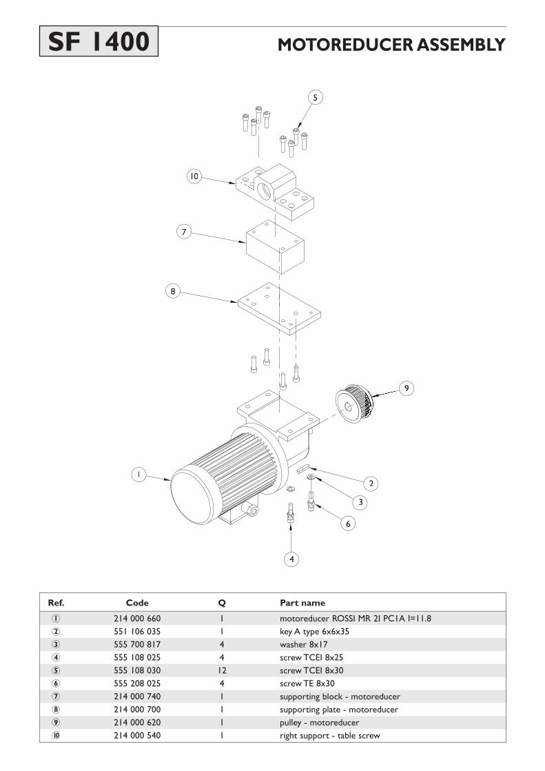
214 000 660 1 motoreducer ROSSI MR 2I PC1A I=11.8551 106 035 1 key A type 6x6x35555 700 817 4 washer 8x17555 108 025 4 screw TCEI 8x25555 108 030 12 screw TCEI 8x30555 208 025 4 screw TE 8x30214 000 740 1 supporting block - motoreducer214 000 700 1 supporting plate - motoreducer214 000 620 1 pulley - motoreducer214 000 540 1 right support - table screw
1
2
3
4
5
6
7
8
9
10
MOTOREDUCER ASSEMBLYSF 1400

1
14
12
6
4
7
23
4
10
9
85
13
SCREW ASSEMBLYSF 1400

Ref. Code Q Part name
520 170 042 1 bearing 6203 2R 17-40-12521 170 400 2 bearing 30203 17-40-13.25550 117 100 1 self-locking nut 17x1551 105 020 1 key A type 5x5x20551 105 025 1 key A type 5x5x25555 108 025 4 screw TCEI 8x25555 108 030 8 screw TCEI 8x30214 000 460 1 extension - table screw214 000 500 1 feed nut - table screw546 725 510 1 drive belt 255L100214 000 580 1 driven pulley - table screw214 000 360 1 left support - table screw214 000 540 1 right support - table screw214 000 420 1 table screw
1
2
3
4
5
6
7
8
9
10
11
12
13
14
SCREW ASSEMBLYSF 1400

TABLE ASSEMBLYSF 1400
1
2
3
4
5
6
7
8
9 10
11
12
13
14
15
16
17
18
19
20
21
2223
24
Ref. Code Q Part name
547 000 218 2 handwheel B193/359 M8x40555 751 006 44 nut M6555 750 610 41 screw TCB 6x10555 750 620 14 screw TCB 6x20555 104 016 1 screw TCEI 4x16555 106 040 2 screw TCEI 6x40555 106 065 16 screw TCEI 6x65555 106 070 1 screw TCEI 6x70555 108 080 4 screw TCEI 8x80555 306 012 2 screw TSPEI 6x12213 101 460 1 stroke-end bar214 000 520 1 nut support214 001 300 1 cental spacer - stroke-end bar213 101 500 2 spacer - stroke-end bar213 101 540 2 direction stop214 001 160 1 front spar214 001 180 1 back spar214 001 270 2 spring - table214 000 860 4 slide214 001 250 4 cover pin214 001 260 4 pin block214 001 240 2 end cover214 001 200 2 ways cover - table214 000 120 1 table
1
2
3
4
5
6
7
8
9
10
11
12
13
14
15
16
17
18
19
20
21
22
23
24

SPLASH GUARD ASSEMBLYSF 1400
1
4
2
5
7
3
6
Ref. Code Q Part name
555 751 006 44 nut M6555 750 610 41 screw TCB 6x10555 750 625 18 screw TCB 6x25214 001 130 1 table enclosure213 008 160 2 PVC curtain213 008 200 4 curtain rods555 700 613 18 washer 6x13
1
2
3
4
5
6
7

ELECTRIC BOX ASSEMBLYSF 1400
Ref. Code Q Part name
547 000 410 3 hinge - 422811 CFD.40 B-M4541 900 067 1 RPM display - EMI 418541 900 067 2 air grating - LUME 17702540 010 900 1 lock - LUME 17800/17804/178026/17850542 001 050 1 white light (S6/V - ER 507840)213 102 980 1 internal panel213 102 952 1 electrical box
1
2
3
4
5
6
7
1
2
3
4
5
6
7

2
3
4
5
6
7
8
9
Ref. Code Q Part name
542 001 030 1 emergency push-button (PFB2-40/V-ER506320)541 100 425 2 unstable manipulator GE P9MMN2t+P9B10VN541 900 029 2 potentiometer 10KΩ with handle542 001 130 2 double push-button (IPL2.2+3/SIM-ER502460)542 201 020 1 step switch 0-1 SNL1CD/V542 201 010 1 step switch w/handle (LFC-A-3-451 + lc11-045-11)555 750 610 6 screw TCB 6x10214 001 110 1 control panel SF1400541 100 428 1 manipulator GE P9MMN2T+P9B10VN+2p9B20VN
1
2
3
4
5
6
7
8
9
CONTROL PANEL ASSEMBLYSF 1400

3957/981,9(56$/),;785(
20030627

5HI &RGH 4 3DUWQDPH
1 201 500 080 1 bar L=980 mm2 201 500 240 1 yoke3 210 500 440 1 eccentric cam4 538 015 050 1 15x50 spring5 201 500 280 2 clamp bolt6 201 500 360 1 yoke bolt7 201 500 500 1 steel plate8 201 500 160 1 clamp - right end9 201 500 040 1 clamp - left end
10 201 500 200 1 fine adjuster11 543 014 020 1 3/8" plug12 201 500 400 1 eccentric screw13 555 751 010 2 nut M1014 555 701 020 2 10x20 washer15 555 110 025 2 TCEI M10x25 screw16 555 212 050 1 TE M12x50 screw17 555 210 060 1 TE M10x60 screw18 201 500 520 2 jack base19 201 500 600 2 regulating nut20 201 500 560 2 jack bolt L = 122mm PV231221 201 591 040 2 jack bolt L = 190mm PV231922 201 591 080 2 jack bolt L = 304mm PV233023 555 612 060 6 M 12x60 T-bolt
20030627
3957/981,9(56$/),;785(