setup reference guide for kx-ns1000 to sbc...
TRANSCRIPT

Setup Reference Guide for KX-NS1000 to SBC interconnection
Method of connection by "WAN Global IP address directly" (i.e. SBC is the Perimeter Router device.)
Panasonic IP-PBX (KX-NS1000 Version2 series), Media5 Session Border Controller (Mediatrix501 series SBC)
Version 1.1 (PSNJ) 6th.March 2013
Attention: The content of this document is made up by verification results. It is no guarantee.
Models Used during verification:
Panasonic IP-PBX KX-NS1000 (Ver2)
Media5s SBC Mediatrix501 (Firmware 5.35-M4)
Panasonic SIP Phone KX-UT series SIP telephones (Version 01.221)
Panasonic System Networks Co., Ltd.

2
Change history
Support PSN (Japan) Version
NO. CONTENTS OF REVISION
Checked by Checked by Author
Oonishi Ver. 1.0 First edition Jan,24 2013
Oonishi Ver. 1.1
Fixed some wrong contents
(3.2 SBC Port Number description) Mar.6th 2013

3
Table of Contents
Setup Reference Guide for KX-NS1000 to SBC interconnection .........................................1
Change history ....................................................................................................................2
Table of Contents ................................................................................................................3
Trademarks .........................................................................................................................4
1. Introduction and Objective ................................................................................................5
2. Approach to interconnection .............................................................................................6
3. System configuration example ..........................................................................................7
3.1 Diagram of system configuration example ...............................................................7
3.2 Settings ....................................................................................................................7
3.3 Media5 SBC Configuration Sheet (WAN Connection) ...........................................13
3.4 SBC Firmware Revision .........................................................................................14
3.5 KX-NS1000 and UT-Extension Firmware Revision ................................................14
4. Initial set-up of the KX-NS1000 ......................................................................................15
5. Procedure for Installing Remote SIP Phone (Remote V-UTEXT) ...................................20
5.1 Procedure for Method 1 with KX-UT Series SIP Phones ........................................21
5.2 Procedure for Method 2 with KX-UT Series SIP Phones ........................................24
5.3 Registering IP Telephones ......................................................................................29
5.4 Full Automatic Mode ...............................................................................................29
5.5 Extension Number Input Mode ...............................................................................29
5.6 Manual Mode .........................................................................................................29
6. Initial setting of the SBC .................................................................................................31
6.1 In Preparation of Network ......................................................................................31
6.2 In Network Configurations (1) ................................................................................34
6.3 In Network Configurations (2) ................................................................................37
6.4 In SIP Server Setting .............................................................................................42
6.5 In SIP Switch Advanced ........................................................................................43
6.6 In SIP Advanced ....................................................................................................44
6.7 Configure the Port Redirection ..............................................................................47
7. Operation ........................................................................................................................48
8. How to register the 3rd party SIP Phones ......................................................................49
8.1 How to make the new SIP Extension (Example) ....................................................49
9. Configure the Remote Office SIP Extension Settings if required ....................................53
9.1 Login and confirmation of info .................................................................................53
9.2 In VoIP Setting ........................................................................................................54
10. Further Information and Configuration ..........................................................................56

4
Table of Contents
11. Management ........................................................................................................57
11.1 Reset SBC to Factory Default .......................................................................57
11.2 Time Setting ...................................................................................................57
11.3 SBC Configuration Backup ............................................................................58
11.4 Restore Settings ............................................................................................60
11.5 Reset the UT-SIP Phone to Factory default ...................................................61
11.6 Allow the access to web page on UT-SIP Phone ...........................................61
12. Troubleshooting ....................................................................................................62
12.1 REGISTER Flood Attack ................................................................................62
12.2 When UT-SIP Phone is repeated a reboot at remote site ..............................63
13. Appendix SBC Configuration Check Sheet (WAN Connection) ............................64
Trademarks
• Microsoft, Windows, Windows XP, Vista, 7 and Internet Explorer are either registered trademarks
or trademarks of Microsoft Corporation in the United States and/or other countries.
• All other trademarks identified herein are the property of their respective owners.
• Microsoft product screen shot(s) reprinted with permission from Microsoft Corporation.
[Important matter]
Configuration Advice
You have to configure the SBCs SIP Trunk settings If you have a SIP trunk connection need
between PBX and ITSP (Internet Telephony Service Provider).
As necessary, refer the additional volume of
“Setup_Guide_for_Media5_SBCs_SIP_Trunk_and_NS1000_Ver2_(WAN_Scenario).doc”.

5
1. Introduction
[Note]
The SIP remote extension(s) are registered to the V-UTEXT32 of NS1000 (Ver.2), it's not the
registration of V-SIPEXT32. We can register the UT-SIP extension as V-UTEXT32 through the
SBC by NS1000 Ver2. This Setup Reference Guide describes mainly using the V-UTEXT32.
Objective:
A Session Border Controller is required to supplement existing IP-PBX functionality.
It will provide the means of establishing a simple remote office connection
(Allowing the use of remote SIP extensions of the IP-PBX without the need for a PPTP, IPSEC, GRE
or Hosted VPN Solution). **** Please Note: HTTPS/SSL is VPN Technology ****
This Setup Reference Guide describes the configuration to interconnect between the Panasonic
IP-PBX (KX-NS1000 Version2 series), the Media5 Session Border Controller (Mediatrix501 series
SBC), and remote SIP Extensions (Panasonic KX-UT series).
The items above are interconnected using SIP, TR069 (CWMP) and NTP protocol. The global IP
address (also known as public IP address) of the main office is used to interconnect them.
Results (confirmed operation):
1-1 Receiving and making a Call
Calls between extensions are possible. The Caller ID (internal phone number) is displayed on the
LCD screen of Panasonic UT-SIP Extension and SIP Extension.
Incoming calls from PBX trunk lines also display the Caller ID (according to system settings).
1-2 Conversation with G.722, G.711 and G.729
Use of the above codec is possible, providing PBX settings allow this. (e.g. KX-NS1000 (V-UTEXT)
settings)
1-3 Placing a call on-hold and retrieving a Call that is on-hold
These features are confirmed by KX-NS1000 control.
1-4 Transferring Call
The transferring of a Call to another destination is confirmed by KX-NS1000 control.
1-5 Call forwarding (V-UTEXT32 Registered)
These features are confirmed by KX-NS1000 control.
* Note* This feature does not work as using registration of SIP extension(V-SIPEXT32).
Restriction on the use of standard SIP Extension (V-SIPEXT32).
Attention: The content of this document is made up by verification results. It is no guarantee.

6
2. Approach to Interconnection
(1) For the Panasonic IP-PBX, the Virtual UT SIP Extension (V-UTEXT32) is used to interconnect
the IP-PBX to a remote UT SIP extension (remote office) via the SBC. The SBC is installed as
the main router in the head office. For this setting of the SBC, WAN and LAN (ET1) interface
are used. All SIP traffic between the IP-PBX and the internet is routed through the Mediatrix
SBC. The SBC is set-up a DHCP server and also as a NAT device.
(2) The SBC operates to ensure correct interconnection between the IP-PBXs V-UTEXT32 virtual
circuit card and the Remote office UT SIP Extension.
The SBC provides the following functions:
- Remote office UT SIP and SIP extensions address resolution and address translation within
SIP messages.
- Head office (any PBX extension) and the remote office (UT SIP Extensions) can be
seamlessly connected by the use of an IP-PBX UT SIP extension.
- Little or no dependence on the setting of the Router of the Remote-Office.
(3) We recommend that you consider the bandwidth of Internet access in each country,
to change the priority of voice Codec G.729 the remote side.
(4) We recommended that you will be use the Port number 5060 of receiving of SIP in SBC.
The SBC is likely to have some interoperability issues when using different SIP port of this.
The SBC will check all SIP messages and modify them even if as use the SIP Trunk in the PBX.
It means the SBC receiving Port Number is "5060" for SIP-Extension and also SIP Trunk.
Therefore we strongly recommend that you set-up the port number 5060 of SBC, due to the
specification of the Media5 SBC.
(5) About Interoperate with Remote SIP Extension and SIP Trunk connection for ITSP.
You have to configure the SBCs SIP Trunk settings if you have a SIP trunk connection need
between PBX and ITSP (Internet Telephony Service Provider).
As necessary, refer the additional volume of Setup Reference Guide for KX-NS1000 to SBC SIP
Trunking.
(6) The NS1000 has protocol HTTPS and HTTP for UT-SIP Phone registration.
The NS1000 can support up to 20 remote extensions at the same time when using the HTTPS
protocol.
The protocol is described the HTTPS type as example in this Setup Reference Guide.

3. System configuration example
3.1 Diagram of system configuration example
Remote OfficeHead Office
7
LAN:192.168.10.254/24
UT-Extensions 301(Panasonic KX-UT series)
Router
HUB
HUBKX-NS1000
Gateway
LAN1:192.168.0.254/24
SBC have to set Port forward settings added, to allow incoming traffic to the SBC and the NS1000(e.g.)To PBX CWMP(HTTP) 7547 ----> 192.168.0.101
CWMP(HTTPS) 37547 ----> 192.168.0.101Data Download(HTTP) 7580 ----> 192.168.0.101Data Download(HTTPS) 37580 ----> 192.168.0.101NTP(UDP) 123 ----> 192.168.0.101
SBC‘s DHCP IP range: 192.168.0.2 – 192.168.0.50
Internet
Note:
Panasonic IP-PBX KX-NS1000 Ver2MPR: 192.168.0.101 (SIP)DSP: 192.168.0.102-105 (RTP)Netmask: 255.255.255.0DGW: 192.168.0.254SIP Ext Server: 192.168.0.101: 5060 WAN: 10.0.0.1/29 :5060
PBX Extension(s): UT-Extension: 201
[ Network Setting ]IP:192.168.10.1/24(DHCP)DGW:192.168.10.254
[ SIP Server by PBX ]Remote Site Settings by Web Maintenance Console (Web MC)*NoteDon’t access the UT-Extension configuration by web.
WAN Global IP address
Method of WAN Connection by Global IP address directly
Provided by ISP
IP address shown here in the range 10.0.0.X are for illustration only.
When applying actual address settings to equipment, these address must be changed to the Global IP address (provided by the ISP).
Maintenance PC
When initial setting only
Media5 SBC WAN: 10.0.0.6
Remote OfficeHead Office
LAN:192.168.10.254/24
UT-Extensions 301(Panasonic KX-UT series)
Router
HUB
HUBKX-NS1000
Gateway
LAN1:192.168.0.254/24
SBC have to set Port forward settings added, to allow incoming traffic to the SBC and the NS1000(e.g.)To PBX CWMP(HTTP) 7547 ----> 192.168.0.101
CWMP(HTTPS) 37547 ----> 192.168.0.101Data Download(HTTP) 7580 ----> 192.168.0.101Data Download(HTTPS) 37580 ----> 192.168.0.101NTP(UDP) 123 ----> 192.168.0.101
SBC‘s DHCP IP range: 192.168.0.2 – 192.168.0.50
Internet
Note:
Panasonic IP-PBX KX-NS1000 Ver2MPR: 192.168.0.101 (SIP)DSP: 192.168.0.102-105 (RTP)Netmask: 255.255.255.0DGW: 192.168.0.254SIP Ext Server: 192.168.0.101: 5060 WAN: 10.0.0.1/29 :5060
PBX Extension(s): UT-Extension: 201
[ Network Setting ]IP:192.168.10.1/24(DHCP)DGW:192.168.10.254
[ SIP Server by PBX ]Remote Site Settings by Web Maintenance Console (Web MC)*NoteDon’t access the UT-Extension configuration by web.
WAN Global IP address
Method of WAN Connection by Global IP address directly
Provided by ISP
IP address shown here in the range 10.0.0.X are for illustration only.
When applying actual address settings to equipment, these address must be changed to the Global IP address (provided by the ISP).
Maintenance PC
When initial setting only
Media5 SBC WAN: 10.0.0.6
3.2 Settings:
This section describes the network address scheme. Refer to later sections regarding entry of these
and other settings.
3.2-1 SBC – Contents of Main Network Settings (Example)
Item Configuration Description
WAN Interface: IP address 10.0.0.1 (Change to
Global IP address)
Required (Information offered by provider)
WAN Interface: Netmask 255.255.255.248 Required (Information offered by provider)
WAN Interface: Gateway 10.0.0.6 (Change to
Global IP address)
Required Information offered by provider)
LAN interface IP address 192.168.0.254 SBC LAN IP address
LAN interface Netmask 255.255.255.0 SBC LAN side subnet mask
Receiving SIP port 5060 SIP port used (Do not use different number)
Recommended set value
Used RTP port 35000 – 35999 Use for RTP streams
Primary DNS 172.16.255.1 Required (Information offered by provider)
DHCP IP From - To 192.168.0.2 -50 SBC’s DHCP Server: Specify an IP range.

8
3.2-2 SBC - Contents of Port Redirection (also known the Port forwarding) Settings (Example)
Protocol Port number Destination Description
CWMP(HTTP) 7547
(TCP)
192.168.0.101 Send CWMP to PBX
(PBX LAN IP address)
CWMP(HTTPS) 37547
(TCP)
192.168.0.101 Send CWMP to PBX
(PBX LAN IP address)
SIP-MLT Data
Download(HTTP)
7580
(TCP)
192.168.0.101 Send Data to PBX
(PBX LAN IP address)
SIP-MLT Data
Download(HTTPS)
37580
(TCP)
192.168.0.101 Send Data to PBX
(PBX LAN IP address)
NTP 123
(UDP)
192.168.0.101 Send NTP to PBX
(PBX LAN IP address)
3.2-3 IP-PBX (NS1000) - Contents of Main Network Settings (Example)
PBXs IP Address/Ports Settings
Item Configuration example Description
PBX MPR IP address 192.168.0.101 Example only (Fixed IP)
PBX DSP IP address 192.168.0.102 - 105 Example only (Fixed IP)
Net Mask 255.255.255.0 Example only
Gateway 192.168.0.254 SBC LAN IP address
DNS Settings
(Preferred DNS IP Address)
172.16.255.1
or 192.168.0.254 (SBC LAN)
Information offered by provider
or SBC LAN IP address
PBX DHCP Server Feature
Starting IP address
Ending IP address
192.168.0.51
192.168.0.100
If required
Note) Set the different IP range
from SBC’s DHCP IP range.
3.2-4 IP-PBX (NS1000) - Confirmation of current each [Port Number] on Site Property (Example)
Port Number Item Configuration example Description
UDP Port No. for SIP Extension
Server
5060 Default (SIP Port Number)
CWMP (HTTP) Port No. for
SIP-MLT
7547 Default
CWMP (HTTPS) Port No. for
SIP-MLT
37547 Default
Data Transmission Protocol
(HTTP) Port No. for SIP-MLT
7580 Default
Data Transmission Protocol
(HTTPS) Port No. for SIP-MLT
37580 Default
9
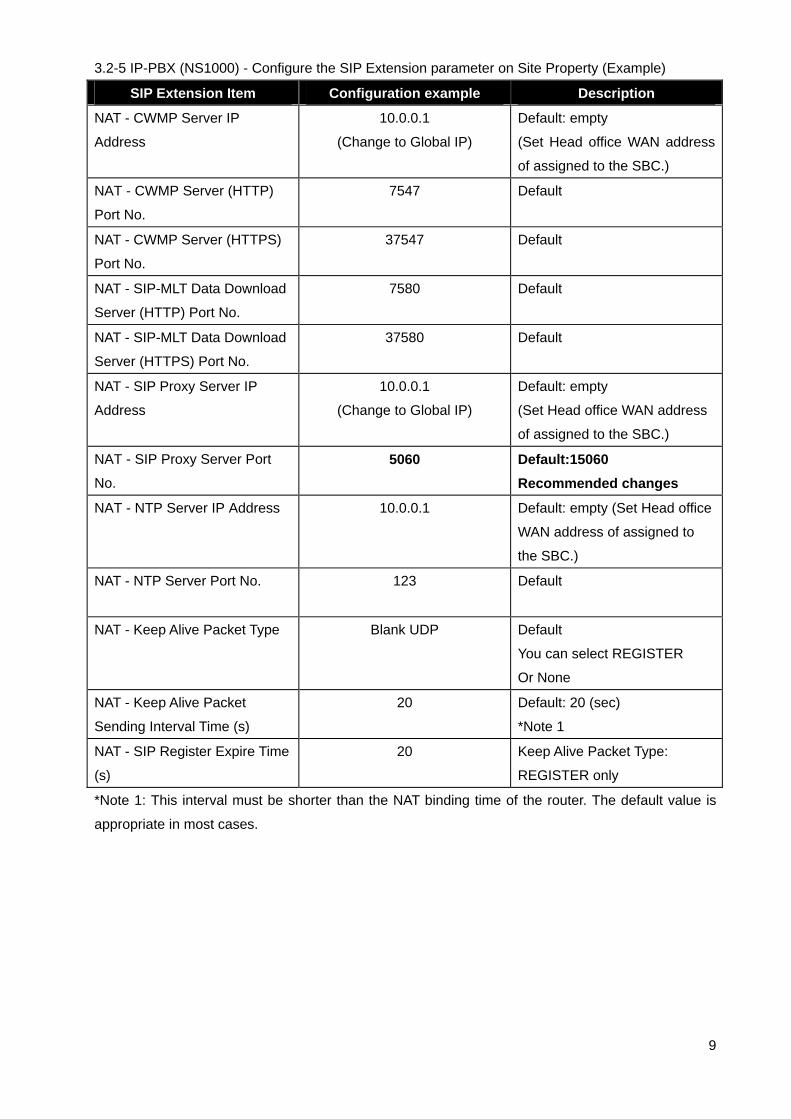
3.2-5 IP-PBX (NS1000) - Configure the SIP Extension parameter on Site Property (Example)
SIP Extension Item Configuration example Description
NAT - CWMP Server IP
Address
10.0.0.1
(Change to Global IP)
Default: empty
(Set Head office WAN address
of assigned to the SBC.)
NAT - CWMP Server (HTTP)
Port No.
7547 Default
NAT - CWMP Server (HTTPS)
Port No.
37547 Default
NAT - SIP-MLT Data Download
Server (HTTP) Port No.
7580 Default
NAT - SIP-MLT Data Download
Server (HTTPS) Port No.
37580 Default
NAT - SIP Proxy Server IP
Address
10.0.0.1
(Change to Global IP)
Default: empty
(Set Head office WAN address
of assigned to the SBC.)
NAT - SIP Proxy Server Port
No.
5060 Default:15060
Recommended changes
NAT - NTP Server IP Address 10.0.0.1 Default: empty (Set Head office
WAN address of assigned to
the SBC.)
NAT - NTP Server Port No.
123 Default
NAT - Keep Alive Packet Type
Blank UDP Default
You can select REGISTER
Or None
NAT - Keep Alive Packet
Sending Interval Time (s)
20 Default: 20 (sec)
*Note 1
NAT - SIP Register Expire Time
(s)
20 Keep Alive Packet Type:
REGISTER only
*Note 1: This interval must be shorter than the NAT binding time of the router. The default value is
appropriate in most cases.

10
3.2-6 IP-PBX (NS1000) - Configure the Options of Recommended P2P Group (Example)
System options P2P Group
(2.9-Option 7)
Configuration example Description
Priority Voice 1 G729 Default: G729
Priority Voice 2 G711 Default: G711
Priority Voice 3 None Default: G722
3.2-7 IP-PBX (NS1000) - Configure the Group of P2P (Example)
P2P Group (3.10) Configuration example Description
P2P Group
P2P Group Name
Bandwidth Control
1
Empty
Disable
Default
Default: Empty
Default: Disable
P2P Group
P2P Group Name
Bandwidth Control
2
Remote Office
Enable
Default
Example
Default: Disable
3.2-8 IP-PBX (NS1000) - Contents of Remote UT Extension (SIP-MLT) Settings (Example)
Item Configuration example Description
[Port Property Main]
SIP Extension Number
Password
P2P Group
[Option tab]
Codec Priority
[Remote Place tab]
Phone Location
Protocol for Remote SIP-MLT
301
1234
2
*1st: G729A / 2nd:G711A/
3rd:G722Mu / *4th: G722
Remote
HTTPs
Example
Default
Default:1
*1st: G722 / 2nd:G711A/
3rd:G722Mu / *4th: G729A
Default: Local
Default: HTTP
[Port Property Main]
SIP Extension Number
Password
P2P Group
[Option tab]
Codec Priority
[Remote Place tab]
Phone Location
Protocol for Remote SIP-MLT
302
1234
2
*1st: G729A / 2nd:G711A/
3rd:G722Mu / *4th: G722
Remote
HTTPs
Example( If required)
Default
Default:1
*1st: G722 / 2nd:G711A/
3rd:G722Mu / *4th: G729A
Default: Local
Default: HTTP
11
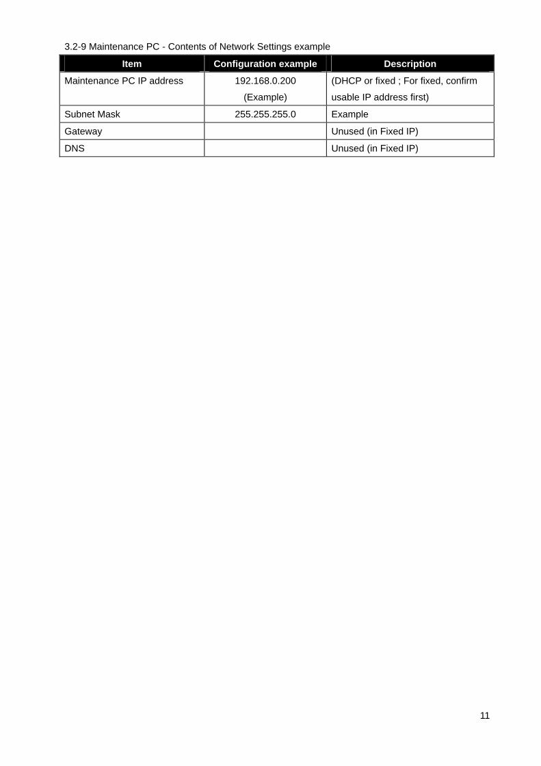
3.2-9 Maintenance PC - Contents of Network Settings example
Item Configuration example Description
Maintenance PC IP address 192.168.0.200
(Example)
(DHCP or fixed ; For fixed, confirm
usable IP address first)
Subnet Mask 255.255.255.0 Example
Gateway Unused (in Fixed IP)
DNS Unused (in Fixed IP)

12
3.2-10 Remote Office UT Extension - Contents of automatically downloaded settings via TR069.
(Example) * Note1: Unless specifically instructed to do so, please do not directly configure the
UT-SIP Phone via the web as this will interfere with the configuration settings delivered by the PBX.
Item Configuration example Description
UT SIP Phone: IP address DHCP(Example, 192.168.10.1)
UT SIP Phone: Netmask DHCP(Example, 255.255.255.0)
UT SIP Phone: Gateway DHCP(Example, 192.168.10.254)
Registrar Server Address 10.0.0.1
(Change to global IP address)
(Set Head office WAN
address of assigned to the
SBC.)
Registrar Server Port 5060 SBC SIP receiving port
Proxy Server Address 10.0.0.1
(Change to global IP address)
(Set Head office WAN
address of assigned to the
SBC.)
Proxy Server Port 5060 SBC SIP receiving port
SIP Service Domain 192.168.0.101:5060 Example
PBX SIP Server Domain
Need to add a :port number
SIP source port 25060 Source port for outgoing SIP
* Measures for SIP ALG
function in Remote router.
NAT Identity Keep Alive Interval 20 (second) Example (Default: 20)
NAT Identity Supports Rport Yes Example (Default: Yes)
SIP extension Number
Password
301
pass301
Example
SIP extension Number
Password
302
pass302
Example (if required)
3.2-11 Remote Office Existing Router - Contents of main network settings
Item Configuration example Description
WAN global IP address Fixed IP or It will provide different IP
address from ISP every time.
Existing remote office router
WAN IP address.
LAN IP address 192.168.10.254 Existing remote office router
LAN IP address
3.2-12 Remote office router contents of port forward settings
It is not necessary to change any settings of the Router of the remote office when using a SIP
phone with “Keep-Alive” capability. (e.g.) Panasonic KX-UT series SIP Phones.
UT series SIP Phones can send the Keep Alive messages to the SBC (Blank UDP packets).

13
3.3 Media5 SBC Configuration Sheet (Connection type: WAN Connection)
Section Part Item Setting value Description
Home Active Profile Security Low Select
Configuration Network Config Operational mode Router Default
WAN ET0 used as Outside Select
WAN IP Address 10.0.0.1 SBC WAN address
WAN Subnet Mask 255.255.255.248
WAN Access type Manual Select
DNS Server IP Address 172.16.255.1 Example
2nd (DNS Server Address) If required
Default Gateway IP Address 10.0.0.6 Network Gateway
LAN IP Address 192.168.0.254
LAN Subnet Mask 255.255.255.0
DHCP Server Enable
From: / To: 192.168.0.2 -50
SIP Server Allow to Register Inside users All Select
Outside users All Select
Allow outgoing calls from All Select
Advanced Advanced SIP set Far End Nat Traversal (FENT) Select the check
Detect endpoints behind same NAT Clear the check
Advanced Authorized Users Method REGISTER
URI * Enter
Direction Inbound
Allow Select the check
Authentication Select the check
Authentication User IDs * Enter
Advanced Authorized Users Method INVITE
URI *@192.168.0.101 Enter
Direction Inbound
Allow Select the check
Authentication Select the check
Authentication User IDs * Enter
Advanced Reuse received nonces Clear the check
SIP Proxy SIP Server UFP port numbers 5060
Advanced RTP media port range 35000-35999
Allow RTP in reverse direction Select the check
Reuse port number with same session Select the check
Force Real Username on registration Select the check
Trusted Networks Check box Clear the check P-Asserted-ID

14
3.3 Media5 SBC Configuration Sheet (2/2) (Connection type: WAN Connection)
Section Part Item Setting value Description
SECURITY
Profile:Low
Port redirection Outside Port Inside Host
TCP Local port: 7547
(CWMP port / HTTP)
192.168.0.101
Remote UT-SIP Protocol type.
Select type: HTTP
TCP Local port: 37547
(CWMP port / HTTPS)
192.168.0.101
Remote UT-SIP Protocol type.
Select type: HTTPs
TCP Local port: 7580
(Data download / HTTP)
192.168.0.101
Remote UT-SIP Protocol type.
Select type: HTTP
TCP Local port: 37580
(Data download / HTTPs)
192.168.0.101
Remote UT-SIP Protocol type.
Select type: HTTPs
UDP Local port: 123
(NTP port)
192.168.0.101
Remote UT-SIP time server
3.4 SBC Firmware Revision
Section Installed Firmware
Device Information 5.35-M4 or Later
3.5 KX-NS1000 and UT-Extension Firmware Revision
Section Installed Firmware
KX-NS1000 IP-PBX Version 2.02039 or Later
KX-UT Phone Version Information 01.160 or Later

4. Initial set-up of the NS1000
(Note) The SIP remote extension(s) are registered to the V-UTEXT32 of NS1000 (Ver.2)
4.1 Start up software of web browser. (Internet Explorer Version 7 or later, Mozilla Firefox 6 or later)
4.2 Access the KX-NS1000 Web Maintenance Console page (using previously read IP address).
e.g. http://192.168.0.101/
4.3 Enter Username: INSTALLER, Password:1234 ---> Next, click on [Login].
15
4.4 Access to initial web page (HOME) and Click on [Setup].

4.5 Confirmation of Activation Key (To install if you need the Activation key.)
Click on [PBX Configuration] --> [1.Configuration] --> [1.Slot] --> [Activation Key]
4.6 Confirmation of “IP Phone Capacity and IP Proprietary Telephone Activation (ch) “ key
(In this case, IP Phone Capacity (ch):30 / IP Proprietary Telephone/IP:0 (Note *1).
*Note *1): 30 IP-Extension can be installed to NS-1000 without extra Activation Keys,
but for connecting IP Extension itself. User must purchase IP-Telephones Activation Keys
when expand over 8 Telephones.
4.7 Confirm, then click [OK] to close page.
Install the IP Phone Capacity and IP Proprietary Telephone Activation key if required.
16

4.8 Click on [PBX Configuration] --> [1.Configuration] --> [1.Slot]
--> Move mouse over [Site Property]
4.9 Select [Main] menu.
4.10 Click on [Port Number], --> Confirmation of current parameter value
1. [UDP Port No. for SIP Extension Server]: 5060 (Default)
2. [CWMP (HTTP) Port No. for SIP-MLT]: 7547 (Default)
3. [CWMP (HTTPS) Port No. for SIP-MLT]: 37547 (Default)
4. [Data Transmission Protocol (HTTP) port No. for SIP-MLT]: 7580 (Default)
5. [Data Transmission Protocol (HTTPS) port No. for SIP-MLT]: 37580 (Default)
Note: These each parameter of PBX in LAN side are using default value in this example.
17

4.11 Configure SIP Extension into the IP-PBX (NS1000) for Remote SIP Extension.
Click on [SIP Extension] --> Edit the each parameters
4.12 Click on [Apply] and [OK] to close page.
--> *) Perform System Reset for changes to take effect
[ Setting parameters assigned to Remote SIP-MLT ] (Example)
NAT - CWMP Server IP Address : 10.0.0.1 (This is an example, Change to Global IP)
NAT - CWMP Server (HTTP) Port No. : 7547 (This is a default value.)
NAT - CWMP Server (HTTPS) Port No. : 37574 (This is a default value.)
NAT - SIP-MLT Data Download Server (HTTP) Port No.: 7580 (This is a default value.)
NAT - SIP-MLT Data Download Server (HTTPS) Port No: 37580 (This is a default value.)
NAT - SIP Proxy Server IP Address: 10.0.0.1 (This is an example, Change to Global IP)
NAT - SIP Proxy Server Port No.: 5060 (Recommended changes) *Note Refer to 2. Approach (4)
NAT - NTP Server IP Address: 10.0.0.1 (This is an example, Change to Global IP)
NAT - NTP Server Port No.: 123 (This is a default value.)
NAT - Keep Alive Packet Type: Blank UDP (This is a default value)
NAT - Keep Alive Packet Sending Interval Time (s): 20 (This is a default value)
NAT - SIP Register Expire Time (s):20 (This is a default value.) 18

4.13 Configure the P2P Group recommended settings. (Example)
*Note) We recommend that you consider the bandwidth of Internet access in each country,
to change the priority of voice Codec G729 the remote side.
Click on [2.System] --> [9.System Options] --> [Option7]
Configure each Priority Voice of P2P. --> Click on [Apply].
4.14 Click on [3.Group] --> [10.P2P Group] --> Enter Group Number “2” (Example)
Enter the P2P Group Name: Remote Office (Example)
Select [Enable] in the [Bandwidth Control] column for P2P Group that will be used
at a remote site.
4.15 Click on [Apply] --> Click on [OK]
19
Priority Voice 1: Select [G729]
Priority Voice 2: Select [G711]
Priority Voice 1: Select [None]
(Recommended settings)
P2P Group Configuration

20
5. Procedure for Installing Remote SIP Phone (Remote V-UTEXT32).
There are 2 methods to install UT-SIP Phones (V-UTEXT32) at same local site as PBX and at remote
site.
[ Method 1 ]
Connect the UT-SIP Phone to the PBX, register the UT-SIP Phone to the PBX, and then configure
remote V-UTEXT32 settings using Web Maintenance Console.
[ Method 2 ]
Configure the UT-SIP Phone remote settings using the Web user interface of the UT-SIP Phone. You
do not have to connect the UT-SIP Phone to the PBX when using this method.
* Note)
1. A KX-NS1000 can work with only one SBC. Also, multiple sites can share an SBC.
2. KX-UT series SIP Phones can communicate over a NAT (Network Address Translation)-enabled
network only when communicating via an SBC from the KX-NS1000 to which the KX-UT series SIP
Phones are registered.
3. When an SBC is in use, packets from P2P communication also go through the SBC. Therefore, the
number of maximum calls is limited according to the maximum number of calls of the SBC.
4. When installing KX-UT series SIP Phones at a remote site where the time zone is different, those
KX-UT series SIP Phones will not match the Daylight Saving Time, and Time Display of the remote
site. The KX-UT series SIP Phones will act according to the time setting of the KX-NS1000 to which
the SIP Phones are registered.
However, if the KX-UT series SIP Phones are registered to a V-SIPEXT card and if an NTP server is
specified by the SIP Phone, the Daylight Saving Time and Time Display match the KX-UT series SIP
Phone setting.

5.1 Procedure for Method 1 with KX-UT Series SIP Phones.
Configure the V-UTEXT32 card for KX-UT series SIP Phone registration.
* Note) This procedure differs according to the IP Terminal Registration Mode already set to your
KX-NS1000.For details about how to configure the V-UTEXT32 card in each mode, refer to
"Installation Manual 5.9.1 Registering IP Telephones".
5.1-1 Click on [PBX Configuration] --> [1.Configuration] --> [1.Slot] --> [Virtual] --> [V-UTEXT32]
5.1-2 Move the mouse pointer over the V-UTEXT32 card (Virtual UT Extension Card).
A menu will be shown under the mouse pointer. --> Click on [Port Property].
5.1-3 Select [2] (Example) in the P2P Group column for each UT-SIP Phone that will be used
at a remote site.
21

5.1-4 Configure the [UT Codec Priority]
Click on [Option] tab
Select UT Codec Priority- 1st: G729A
Select UT Codec priority- 4th: G722
22
5.1-5 Configure the [Remote Place]
Click on [Remote Place] tab
Select [Remote] in [Phone Location] column for SIP Phone that will be used at a remote site.
Select [HTTPs] in [Protocol for Remote SIP-MLT] column for SIP Phone that will be used
at a remote site.
5.1-6 Click on [Apply] and [OK]
5.1-7 Reboot UT-Phone by “Power reset or RESET command” with UT- Phone manually.
The UT-SIP Phone will download Remote site settings automatically.
5.1-8 Please wait until UT-SIP Phone is received the Remote Extension configuration.
The UT-SIP Phone will download the Remote Configuration parameters.
The UT-SIP Phone will be shown on display as following message.
Check server and set it.
Connection error (90002)
* Note)
Depending on the model of the existing Router, you may be able to connect to the PBX.

5.1-9 After confirming remote connection to the PBX, re-pack the KX-UT series SIP Phone, and then
send it to the remote site. The UT-SIP Phone completed the settings.
Note:
When the KX-UT series SIP Phone is connected at the remote site, it should start normally.
If the KX-UT series SIP Phone cannot connect normally, import the configuration file of
“UT_ACS_HTTPS_01NS1000.cfg or UT_ACS_NS1000.cfg” again as with "Procedure for
method 2" using the Web user interface after initialize.
5.1-10 Unpack the UT-SIP Phone and connect it to the LAN.
The UT-SIP Phone will connect to the Head office PBX via SBC.
And, the UT-SIP Phone will be shown as following on display (Example).
9 OCT 12:00 TUE
301
5.1-11 Please check the Basic outgoing and incoming calls.
23
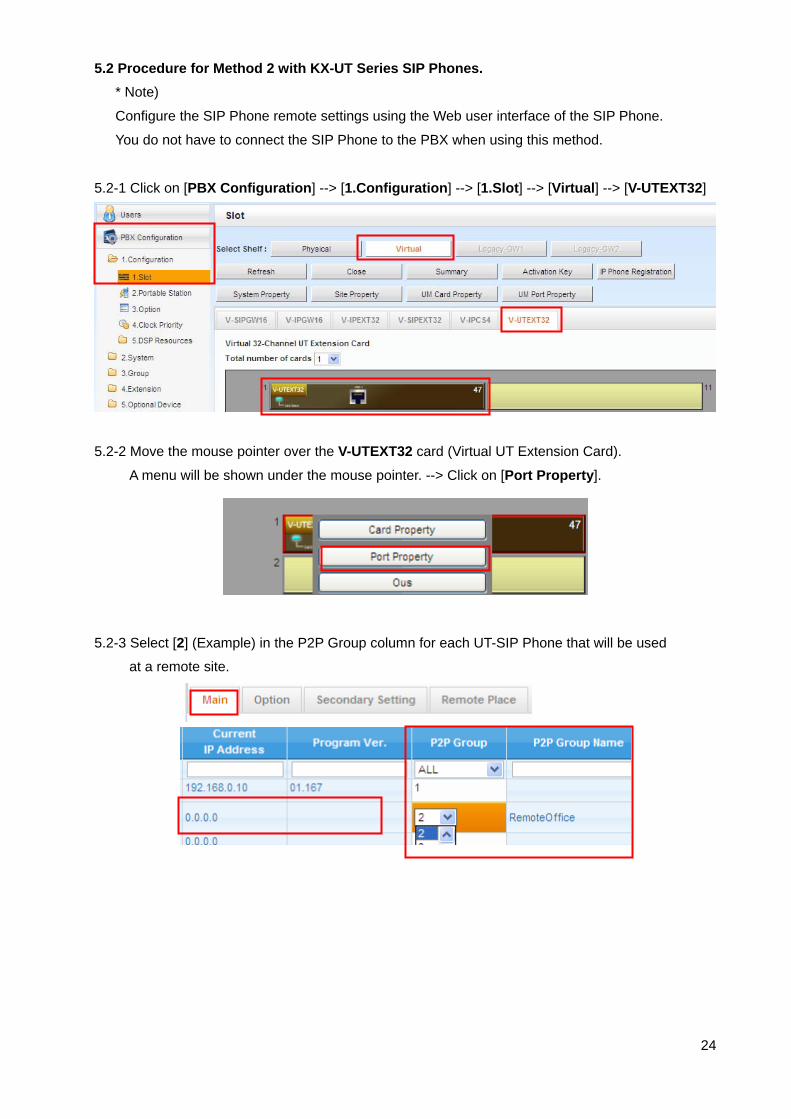
5.2 Procedure for Method 2 with KX-UT Series SIP Phones.
* Note)
Configure the SIP Phone remote settings using the Web user interface of the SIP Phone.
You do not have to connect the SIP Phone to the PBX when using this method.
5.2-1 Click on [PBX Configuration] --> [1.Configuration] --> [1.Slot] --> [Virtual] --> [V-UTEXT32]
5.2-2 Move the mouse pointer over the V-UTEXT32 card (Virtual UT Extension Card).
A menu will be shown under the mouse pointer. --> Click on [Port Property].
5.2-3 Select [2] (Example) in the P2P Group column for each UT-SIP Phone that will be used
at a remote site.
24

5.2-4 Configure the [UT Codec Priority]
Click on [Option] tab
Select UT Codec Priority- 1st: G729A
Select UT Codec priority- 4th: G722
25
5.2-5 Configure the [Remote Place]
Click on [Remote Place] tab
Select [Remote] in [Phone Location] column for SIP Phone that will be used at a remote site.
Select [HTTPs] in [Protocol for Remote SIP-MLT] column for SIP Phone that will be used
at a remote site.
5.2-6 Click on [Apply]
5.2-7 Save the System Data.
Click on [Save System Data]
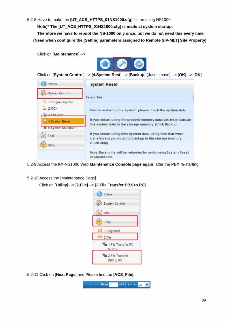
5.2-8 Have to make the [UT_ACS_HTTPS_01NS1000.cfg] file on using NS1000.
Note)* The [UT_ACS_HTTPS_01NS1000.cfg] is made at system startup.
Therefore we have to reboot the NS-1000 only once, but we do not need this every time.
(Need when configure the [Setting parameters assigned to Remote SIP-MLT] Site Property)
Click on [Maintenance] -->
Click on [System Control] --> [4.System Rest] --> [Backup] (Just in case) --> [OK] --> [OK]
5.2-9 Access the KX-NS1000 Web Maintenance Console page again, after the PBX re-starting.
26
5.2-10 Access the [Maintenance Page]
Click on [Utility] --> [2.File] --> [2.File Transfer PBX to PC]
5.2-11 Click on [Next Page] and Please find the [ACS_File].

5.2-12 Click on [UT_ACS_HTTPS_01NS1000.cfg] line.
27
5.2-13 Click on [Transfer]
5.2-14 Save as to in Maintenance's PC folder.
File Name: UT_ACS_HTTPS_01NS1000.cfg
5.2-15 Distribute to the PC to install this file.
5.2-16 The NS1000 completed for the settings of remote UT-SIP extension.
Next, we have to access to UT-SIP Phone web setting page.
5.2-17 Allow to access the UT SIP Phone’s web page
Enter [Setting] on UT-SIP Phone --> Enter [#], [5], [3], [4] --> Select [On] --> [Enter]
5.2-18 Confirm the assigned IP address for UT-SIP Phone.
Click on [Setting] on UT-SIP Phone --> Select [Information Display] --> [Enter]
--> Select [IP Address] 192.168.10.1 (Example) --> Enter [CANCEL] Key
Access the UT-SIP Phone web page. http://192.168.10.1/ (Example)
5.2-19 [Operator Login]
Username: instoperatoruserid
Password: instpass
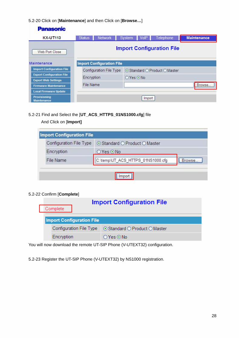
5.2-20 Click on [Maintenance] and then Click on [Browse…]
28
5.2-21 Find and Select the [UT_ACS_HTTPS_01NS1000.cfg] file
And Click on [Import]
5.2-22 Confirm [Complete]
You will now download the remote UT-SIP Phone (V-UTEXT32) configuration.
5.2-23 Register the UT-SIP Phone (V-UTEXT32) by NS1000 registration.

5.3 Registering IP Telephones
After the programming of the PBX and IP telephones is finished
(refer to "5.8 Assigning Networking Information to IP Telephones" in the Installation Manual), the IP
telephones must be registered to the PBX.
The procedure for registering IP telephones differs according to the IP terminal registration mode
specified during the Easy Setup Wizard. This setting can also be changed in the Site Property -
Main screen of the Web Maintenance Console (refer to "9.5.1 PBX Configuration - [1-1] Configuration
- Slot - Site Property - Main - Main - IP Terminal Registration Mode" in the PC Programming Manual).
Refer to the following table:
1.Full Automatic mode 2. Extension Input mode 3. Manual Mode
UT Series
(V-UTEXT32)
Yes No Yes
5.4 Full Automatic Mode
If networking settings have been completed, when IP-PTs or KX-UT series SIP Phones are connected
to the same network as the PBX, they will be registered automatically. No registration procedure is
required.
5.5 Extension Number Input Mode
For KX-UT Series SIP Phones
If networking settings have been completed, when KX-UT series SIP Phones are connected to the
same network as the PBX, they will be registered automatically as same as when they are registered
in Full Automatic mode. No registration procedure is required.
*Note)
UT series do not support “Extension Input Mode”, so even if you set registration mode to
“Extension Input Mode”, the way of registration is same as “Full Automatic Mode”.
Please refer “Full Automatic” explanation.
29

5.6 Manual Mode
5.6-1 Manual Mode (Example)
Select the Port Property – Virtual UT Extension --> Click on [Registration]
30
5.6-2 Select Extension Number for Registration (Example)
Click on [Next] --> [Next]
5.6-3 Wait a [Registration Executing]
5.6-4 Confirm [Registration Completed] and click on [Close]

6. Initial setting of the Mediatrix SBC (Mediatrix 500 series)
6.1 In Preparation of Network
6.1-1 The SBC has a default IP address of 192.168.0.1, Subnet mask: 255.255.255.0
Connect the ET1 of SBC and maintenance PC Network directly.
The SBC’s DHCP server function is running with the SBC, it’s default setting.
In this document, the Network setting is described using obtain an IP configuration automatically.
As a matter of course you can use static IP address.
31
6.1-2 Confirmation of PC LAN settings to allow setup of Mediatrix SBC
[View Network Connections] Select the LAN in use.
I
6.1-3 [Local Area Connection Properties] – Right click and Select the [Properties].

6.1-4 Select [Internet Protocol (TCP/IP)] and Click on [Properties].
32
6.1-5 Confirmation of Network Properties and Click on [OK].
Enter IP Address and Subnet mask for My PC
Example Select the check box Obtain an IP address automatically Click to [OK] --> [Close]
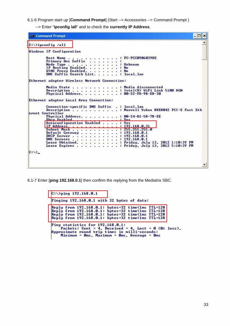
6.1-6 Program start up [Command Prompt] (Start --> Accessories --> Command Prompt )
--> Enter “ipconfig /all“ and to check the currently IP Address.
6.1-7 Enter [ping 192.168.0.1] then confirm the replying from the Mediatrix SBC.
33

6.2 In Network Configurations (1)
6.2-1 Access to Web Home and Click on [Log in]. Example http://192.168.0.1/
6.2-2 To Enter Network Password Username: admin / Password: admin (Default).
34

6.2-3 Access to initial web page (HOME) --> Click on [Network]
35
6.2-4 Confirmation of LAN settings.
6.2-5 Configure LAN IP Address, Subnet Mask and DHCP Server Range (From To).
Click on [Apply]
These are default setting value.

6.2-6 Access to Web Home with New IP address and Click on [Log in].
Example http://192.168.0.254/
6.2-7 Click on [Click here to save permanently]
36

6.3 In Network Configurations (2)
6.3-1 Move mouse over [Home] and Select [Overview]
6.3-2 Select Active Profile: [Low] and Click on [Change]
37
6.3-3 Click on [Click here to save permanently] and then Click on [Network].
5.3-4 Confirmation of Active Profile: [Lo] and Click on [Network].
6.3-5 Confirmation or Selection of Operational mode: [Router]

6.3-6 Network Configuration
[ET0 Settings]-- Select the Access type: [Manual]
-- ET0 used as [outside] (Default) / IP Address: 10.0.0.1 / Subnet Mask: 255.255.255.248
[DNS Server]
-- IP Address: 172.16.255.1 Example, (Change to Global IP)
[Default Gateway]
-- IP Address: 10.0.0.6 Example, (Change to Gateway IP)
6.3-7 Click on [Apply]
6.3-8 Click on [Click here to save permanently]
38

6.3-9 Connect to SBC ET1 (to ET4) and Maintenance PC for existing LAN segment.
[Note] Connect the WAN. Connect to the LAN
6.3-10 Reboot the SBC (Recommended operations)
Select [Configurations] --> [Administration]
39
6.3-11 Click on [Reboot]

6.3-12 Wait for Rebooting.
6.3-13 After rebooting --> Configure the IP Address, execute the release and renew.
(Example, dynamic addressing)
6.3-14 Enter the ping 192.168.0.254 on Command Prompt. ---> Confirmation of Reply.
40

6.3-15 Confirm the Network Configuration
Access to web using new IP address and login again. http:// 192.168.0.254/ (Example)
Click on Configuration [Network]
And then confirmation of Operational mode: [Router]
And ET0 settings / DNS / Default Gateway / SIP Routing Trough Extern Firewall settings.
Network Configuration
[ET0 Settings]-- Select the Access type: [Manual]
ET0 used as [outside]
[IP Address: 10.0.0.1 / Subnet Mask: 255.255.255.248(Change to Global IP)
[DNS Server]-- IP Address: 172.16.255.1 Example, (Change to Global IP)
[Default Gateway]-- IP Address: 10.0.0.6 Example, (Change to Gateway IP)
LAN Configuration
[IP Address]: 192.168.0.254 / Subnet Mask 255.255.255.0 (Example)
[DHCP Server]: Enable / From: 192.168.0.2 – 192.168.0.50 (Example)
[Note] Need to factory-reset the SBC if you need to select the operational mode after once
select it.
41

6.4 In SIP Server Setting
6.4-1 Move Mouse over [Applications] --> and Select [SIP Server]
6.4-2 Select Allow to register
-1. Inside Users: [All] (Default)
-2. Outside Users: [All]
-3. Allow outgoing calls from: [All]
-4. Select the check box [and from others after authentication] (Default)
6.4-3 Click on [Apply]
6.4-4 Click on [Click here to save permanently]
42

6.5 In SIP Switch Advanced
6.5-1 Move Mouse over [Applications] --> and Select [SIP Switch Advanced]
6.5-2 Enter the Authorized User. Example
Ext: 301/ SIP Address: [email protected]/ User ID: 301/ Password: 1234
Ext: 303/ SIP Address: [email protected]/ User ID: 302/ Password: 1234
6.5-3 Click on [Apply]
.
6.5-4 Click on [Click here to save permanently]
43
6.6 In SIP Advanced
6.6-1 Move Mouse over [Applications] --> and Select [SIP Advanced]
44
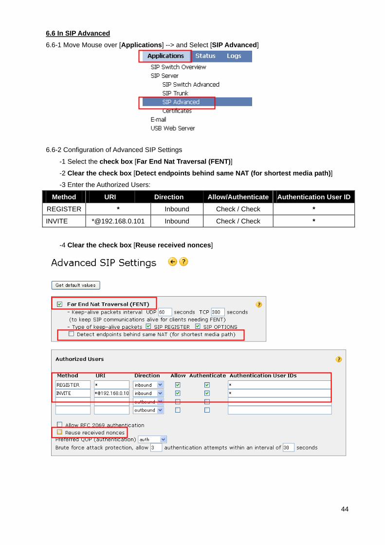
6.6-2 Configuration of Advanced SIP Settings
-1 Select the check box [Far End Nat Traversal (FENT)]
-2 Clear the check box [Detect endpoints behind same NAT (for shortest media path)]
-3 Enter the Authorized Users:
Method URI Direction Allow/Authenticate Authentication User ID
REGISTER * Inbound Check / Check *
INVITE *@192.168.0.101 Inbound Check / Check *
-4 Clear the check box [Reuse received nonces]

6.6-3 Configuration of SIP Proxy
Enter the SIP Server UDP port number: 5060 (Default: 5060)
45
6.6-4 Configuration of Advanced and you can confirm the RTP port range in this page.
-1 Select the check box [Allow RTP in reverse direction]
-2 Select the check box [Reuse port numbers within same session]
-3 Select the check box [Force Real Username on registrations]

6.6-5 Configuration of Trusted networks
Clear the check box [Enable]
46
6.6-6 Click on [Apply]
6.6-7 Click on [Click here to save permanently]

6.7 Configure the Port Redirection
6.7-1 Move the mouse pointer over the [Configurations].
A menu will shown under the mouse pointer --> Click on [Security Low (active)].
6.7-2 Configure Port redirection into the NS1000 for TCP connections and UDP connections.
Contents of Port redirection (also known as Port forwarding) Settings (Example)
Protocol Out side Port (s) Inside Host Description
CWMP(HTTP) 7547
(TCP)
192.168.0.101 Send CWMP to PBX
(PBX LAN IP address)
CWMP(HTTPS) 37547
(TCP)
192.168.0.101 Send CWMP to PBX
(PBX LAN IP address)
SIP-MLT Data
Download(HTTP)
7580
(TCP)
192.168.0.101 Send Data to PBX
(PBX LAN IP address)
SIP-MLT Data
Download(HTTPS)
37580
(TCP)
192.168.0.101 Send Data to PBX
(PBX LAN IP address)
NTP 123
(UDP)
192.168.0.101 Send NTP to PBX
(PBX LAN IP address)
6.7-3 Click on [Click here to save permanently]
47

48
7. Operation
Try the basic calls.
We confirm the following operation by settings in this Reference Guide.
7-1 Incoming Call and making Call
The Caller ID is displayed on the LCD screen of Panasonic UT-SIP Extension and SIP Extension.
7-2 Conversation with G.722 G.711 and G.729
The more than single codec is already set in KX-NS1000 (V-SIPEXT)
7-3 Holding Call and retrieving Call held
These features are confirmed by KX-NS1000 control.
7-4 Transferring Call
The transferring Calls are confirmed by KX-NS1000 control.
7-5 Call forwarding (V-UTEXT32 Registered)
These features are confirmed by KX-NS1000 control.
* Note* This feature does not work as using registration of SIP extension (V-SIPEXT32).
Restriction on the use of standard SIP Extension (V-SIPEXT32).

8. How to register 3rd party SIP Phones
Procedure for Installing Remote SIP Phone (Remote V-SIPEXT32) if required.
This PBX supports the use of 3rd party SIP Phones connected from a remote office over an IP
network through an SBC.
SIP Phones can be set up by simply connecting the Phones to the LAN at the remote office.
If the customer has needs, we can register the 3rd party SIP Phones.
For example, the Media5fone. They have to set a registration method of V-SIPEXT.
8.1 How to make the new SIP Extension (Example)
8.1-1 Configuration of the SIP Extension into the IP-PBX.
Click on [Virtual]
49
8.1-2 Click on [V-SIPEXT32]
8.1-3 Click on [Total number of cards] and Select: 1 (Example)

8.1-4 Click on [OK].
50
8.1-5 Configuration of V-SIPEXT32 Virtual slot.
Move mouse over installed [V-SIPEXT32] card
8.1-6 Select [OUS]
8.1-7 Click on [OK].
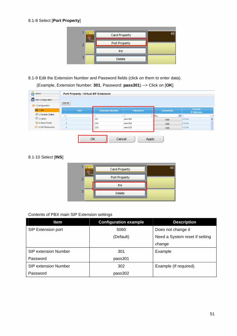
8.1-8 Select [Port Property]
8.1-9 Edit the Extension Number and Password fields (click on them to enter data).
(Example, Extension Number: 301, Password: pass301) --> Click on [OK]
8.1-10 Select [INS]
Contents of PBX main SIP Extension settings
Item Configuration example Description
SIP Extension port 5060
(Default)
Does not change it
Need a System reset if setting
change
SIP extension Number
Password
301
pass301
Example
SIP extension Number
Password
302
pass302
Example (If required).
51

8.1-11 Save the System Data
Click on [Save System Data icon]
[Note]
If you networking settings to change you need "system reset" that click on [System Reset]
During system rebooting, the PBX cannot use.
The PBX preparation completed.
52

9. Configure the Remote Office SIP Extension Settings if required only (Example).
(Here is described as sample for Panasonic KX-UT SIP Phone(KX-UT123)).
We have to configure the SIP terminal via web in case using registration of V-SIPEXT (SIP-SLT)
Connect the SIP-terminal to the LAN. The following explanation assumes the LAN supports DHCP.
(e.g. DHCP server has given the SIP terminal the address 192.168.10.1).
9.1 Login and confirmation of info.
9.1-1 On the telephone, press [Setting or Setup] --> Select the [Network Settings] --> Press [Enter]
--> Select the [Embedded web] --> Press [ENTER] --> Select [ON] --> Press [ENTER]
--> [Back] --> [Back]. Or press [Setting or Setup] [#],[5],[3],[4] Select [On] Press [Enter]
9.1-2 Confirmation of current IP Address.
On the telephone, press [Setting or Setup] --> Select the [Information Display]
--> Press [ENTER] --> Select the [IP Address] confirmation IP Address 192.168.10.1 (Example)
9.1-3 Access the SIP Terminal’s web page (using previously read IP address).
53
e.g. http://192.168.10.1/ User Name: admin / Password: adminpass --> Click on [OK]
9.1-4 Confirmation of Version Information: In this case, 01.160 (Operating Bank: Bank1)
(Software version must be at or later than the version shown)
Running Version
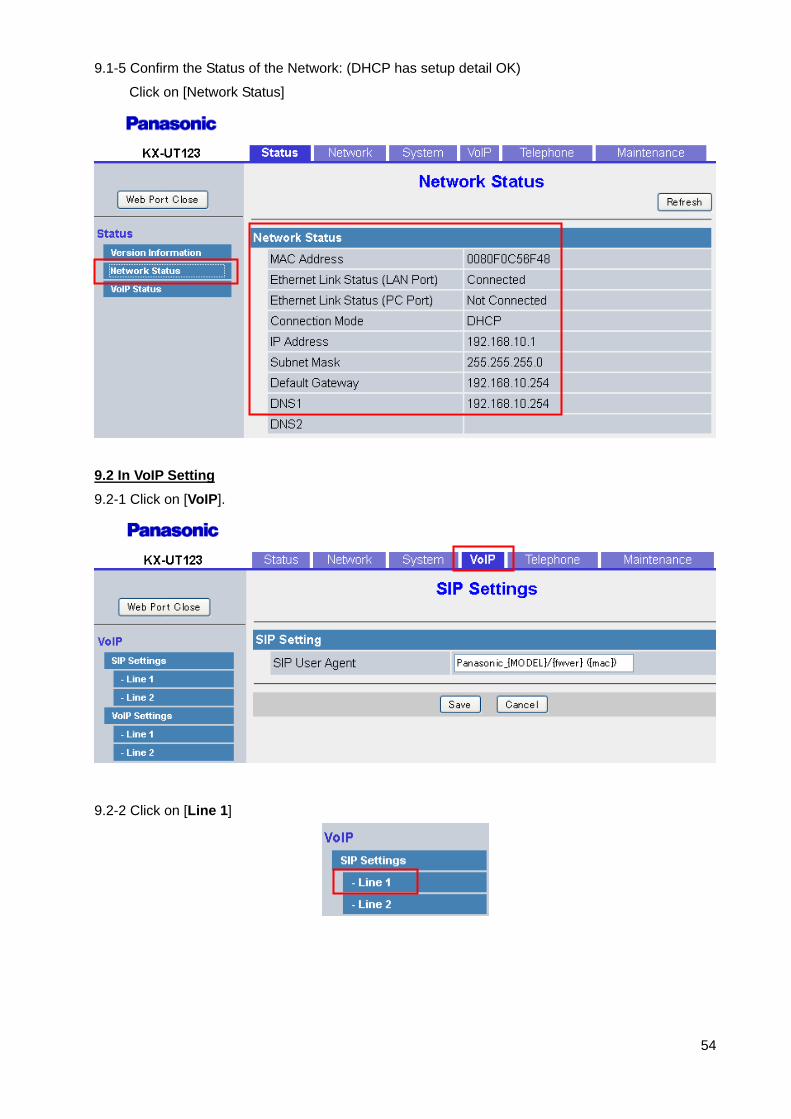
9.1-5 Confirm the Status of the Network: (DHCP has setup detail OK)
Click on [Network Status]
9.2 In VoIP Setting
9.2-1 Click on [VoIP].
9.2-2 Click on [Line 1]
54

9.2-3 Configure the SIP Settings (1 of 3)
9.2-4 Configure the SIP Settings (2 of 3)
55
9.2-5 Configure the SIP Settings (3 of 3)
SIP Settings [Line 1] (1of 3) Phone Number: 301 [SIP Server] Register Server Address: 10.0.0.1 Register Server Port: 5060 Proxy Server Address: 10.0.0.1 Proxy Server Port: 5060 Note: Replace 10.0.0.1 with the WAN address of Head office main router. Change to global IP address.
SIP Settings [Line 1] (2of 3) SIP Service Domain: 192.168.0.101:5060 It’s PBXs LAN IP Address and SIP Port Number SIP Source Port: 25060 Authentication ID: 301 Authentication Password: pass301
SIP Settings [Line 1] (3of 3) Keep Alive Interval: 15 (Seconds) Support Rport: Click on [Yes]
9.2-6 Click on [Save]
9.2-7 Check the [Complete] Message.
The configuration is completed!

56
10. Further SBC Information and Configuration
All documents are available online on the Mediatrix Download Portal at
https://support.mediatrix.com/DownloadPlus/Download.asp.
Or on the web site at the following link
http://www.mediatrix.com/en/sessionbordercontroller Under the documentation tab.

11. Management
11.1 Reset SBC to Factory Defaults
If you wish to you can reset all settings to their original values, so your Mediatrix 500 Series unit is
setup the same way as when delivered from the factory.
1. Press and hold [SET] (1) pressed for 3 seconds, to enter setup mode.
2. Press [SEL] (2) repeatedly until ”RST” appears in the display.
3. Press [SET](1).
4. The question ”Clear all?” appears, and then ”no”.
5. Press [SEL](2) to choose ”YES”.
6. Press [SET](1).
11.2 Time Setting
Time setting will be useful for analyzing some kind of problems.
11.2-1 Move the mouse [Configurations] --> [Administration] --> in the Time section.
11.2-2 Configure the Time Server IP address, this IP is PBX IP address.(Example)
11.2-3 Click on [Apply]
57
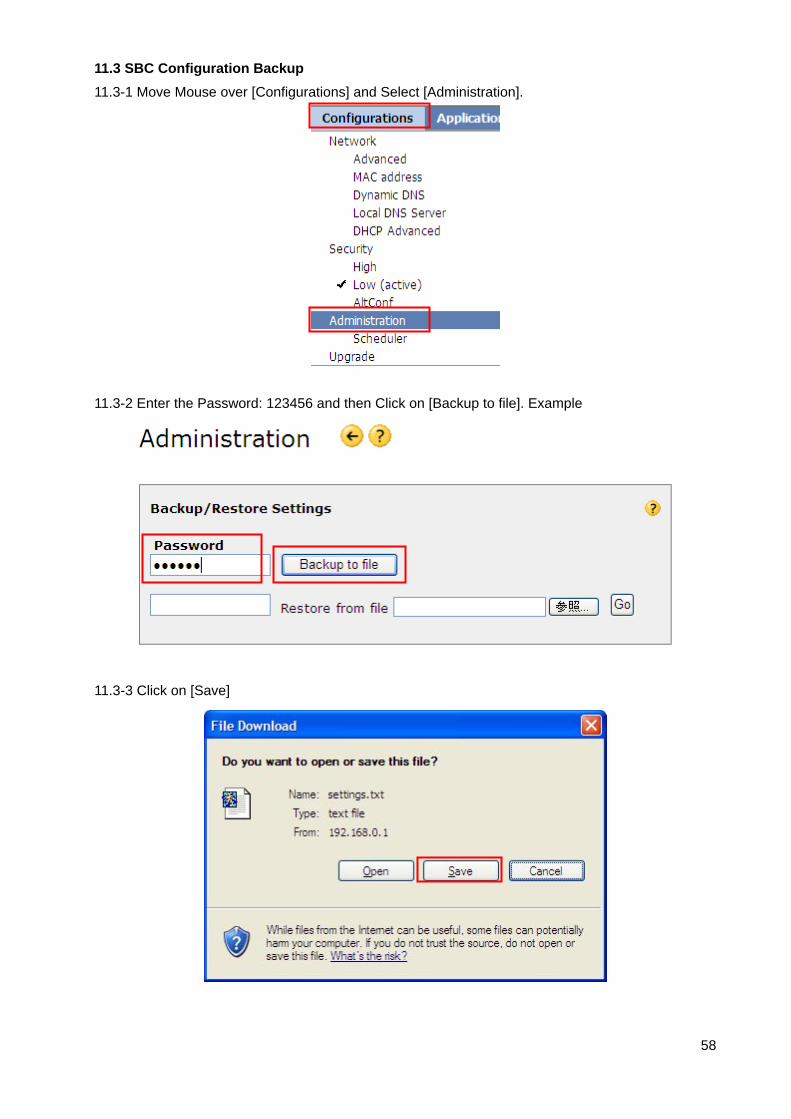
11.3 SBC Configuration Backup
11.3-1 Move Mouse over [Configurations] and Select [Administration].
58
11.3-2 Enter the Password: 123456 and then Click on [Backup to file]. Example
11.3-3 Click on [Save]

11.3-4 Save As
Select the Save Folder and Enter the File name [settings.txt] Example(Default).
59

11.4 Restore Settings
11.4-1 Enter the Password: 123456 (When at saving) and then Click on [Browse…].
60
11.4-2 Choose file: settings.txt (Example) and then Click on [Open].
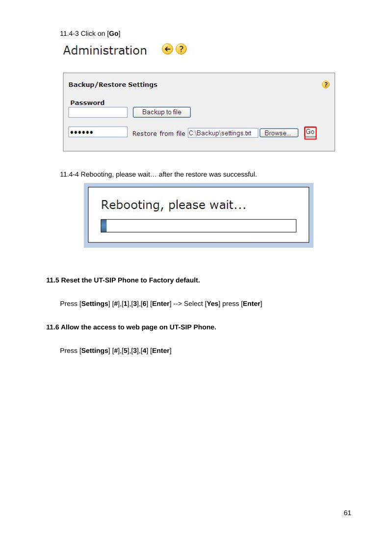
11.4-3 Click on [Go]
11.4-4 Rebooting, please wait… after the restore was successful.
11.5 Reset the UT-SIP Phone to Factory default.
Press [Settings] [#],[1],[3],[6] [Enter] --> Select [Yes] press [Enter]
11.6 Allow the access to web page on UT-SIP Phone.
Press [Settings] [#],[5],[3],[4] [Enter]
61

12 Troubleshooting
12.1 REGISTER Flood Attack
The Figure below shows a REGISTER Flood attack example.
The attack begins with OPTIONS message. Then, the attacker sends a great many REGISTER
messages. The source address changes irregularly.
The symptom of this type of attack is the PBX temporarily becomes un-responsive,
(It is very busy sending “404 Not Found” messages until the attacks over).
Countermeasure:
In the Switch Advanced, Configure a new entry in the Incoming Call Blacklist from captured packets.
12.1-1 Move mouse over Applications in SIP Advanced.
62

12.1-2 Configure a new entry in the Incoming Call Blacklist from captured packets.
User-Agent=*Attacker* (Example)
These are default setting value.
Enter the new entry in Blacklist..
12.1-3 Click on [Click here to save permanently]
12.2 When UT-SIP Phone is repeated a reboot at remote site.
See section 5
1. Check the remote connection protocol whether it match or not.
2. Check the selected Phone location whether it match or not.
63

64
13. Appendix
13.1 SBC Configuration Check Sheet (WAN / Global IP address directly) (1/2)
Section Part Item Setting value Description
Home Active Profile Security Low Select
Configuration Network Config Operational mode Router Default
ET0 used as Outside
IP Address SBC LAN IP address
Subnet Mask SBC LAN Net Mask
Access type Manual
DNS Server IP Address DNS or Main Router IP
2nd (DNS server IP Address) If required
Default Gateway IP Address Main Router LAN IP
SIP Routing
Through Extern
Firewall
Media Ports
(Default 35000-35999)
Must much RTP Port forward
setting of main router
Outside IP Existing main router
Mapped SBCs IP
SIP Server Allow to Register Inside users All Select: All
Outside users All Select: All
Allow outgoing calls from All Select : All
Advanced Advanced SIP set Far End Nat Traversal (FENT) Select the check
Detect endpoints behind same NAT Clear the check
Authorized Users Method REGISTER
URI *
Direction Inbound Select: Inbound
Allow Clear the check
Authentication Clear the check
Authentication User IDs *
Authorized Users Method INVITE
URI *@PBX IP
Direction Inbound Select: Inbound
Allow Select the check
Authentication Select the check
Authentication User IDs *
Advanced Reuse received nonces Clear the check
Allow RTP in reverse direction Select the check
Reuse port number with same session Select the check
Force Real Username on registration Select the check
Trusted Networks Check box Clear the check

65
13.1 SBC Configuration Check Sheet (WAN / Global IP address directly) (2/2)
Section Part Item Setting value Description
Security Port redirection Outside port(s) Inside host
TCP 7547 PBX IP address
TCP 37547 PBX IP address
TCP 7580 PBX IP address
TCP 37580 PBX IP address
UDP 123 PBX IP address