setion 4 ‐ luriation and maintenane -...
TRANSCRIPT

4ï1
SECTION 4 ‐ LUBRICATION AND MAINTENANCE
LUBRICATION
GENERAL INFORMATION
Your baler is designed to require a minimum of
lubrication. However, regular lubrication is the best
insurance against delays and repairs and greatly
increases the life of the machine.
All gearboxes and reservoirs should be checked for
leakage daily.
Use only top grade lubricants stored in clean vessels. Recommended lubricants and amounts are summarized at the back of this manual.
Before greasing always wipe any dirt from the grease
zerks and then apply a good grade of grease. Use
Multi purpose grease classified under NLGI Class 2.
Excess grease should be wiped off.
All grease zerks on the machine are indicated with a
grease decal on which the time interval is mentioned.
1
WARNING To lubricate or service the baler manually: Always disengage the tractor PTO drive, stop the tractor engine, and apply the handbrake. Remove the tractor ignition key before leaving the cab to lubricate the baler. Turn the power off on control instruments in the tractor affecting the baler operation, to prevent accidental tripping of any of the stuffer or knotting mechanisms. Apply the flywheel brake and engage the knotter safety lock. Whenever laying under the baler is needed to carry out any kind of maintenance, support all axles on both sides to avoid getting stuck in case a tire deflates.

SECTION 4 - LUBRICATION AND MAINTENANCE
4ï2
LUBRICATION AND MAINTENANCE QUICK REFERENCE
This section is designed to a give quick and easy way of locating all the grease fittings and carrying out lubrication
and maintenance operations per interval.
SERVICE INTERVALS AND ITEMS
10 HOURS OR 400 BALES OR DAILY
Centralized greasing system (if your machine is not
equipped with the automatic greasing system, grease all five
grease banks)
x 4-5
Automatic greasing system (if fitted) x x 4-15
Ball ring hitch (if fitted) x 4-17
Stuffer clutch pawl x 4-17
Stuffer clutch housing x 4-18
Knotter clutch pawl x 4-18
Knotter clutch housing x 4-18
Automatic oiler system x x 4-23
Crop cutting knife sharpening x x 4-42
Baler x 4-85
Previous + 50 HOURS OR 2000 BALES OR WEEKLY
PTO mid ship bearing x 4-20
Knotter drive PTO (upper and lower) x 4-20
Rear wheel spindles
(on units with tandem Autosteer axle only)
x 4-21
Main drive gearbox x x 4-25
Stuffer drive gearbox x x 4-27
Knotter drive gearbox x x 4-28
Bale density hydraulic circuit x x 4-29
Chain tension x x 4-31
Main PTO drive slip clutch x x 4-34
SECTION 4 - LUBRICATION AND MAINTENANCE
4ï3
Needle safety linkage (Turnbuckle bearing) x 4-19
Shearbolts (knotter, flywheel, stuffer) after 2500 BALES x 4-40
SERVICE INTERVALS AND ITEMS
Previous + 100 HOURS OR 4000 BALES OR MONTHLY
Knotter drive shear hub x 4-20
Linkages, threaded rods and pivots x 4-25
Flywheel brake x 4-21
Main drive gearbox shaft couplers x 4-21
Pick‐ up overrun clutch x 4-22
Parking brake (if fitted) x 4-22
Jack x 4-22
Previous + 250 HOURS OR 10000 BALES OR YEARLY
Integrated automatic oiler (filter) x x 4-24
Stuffer drive gearbox x x 4-27
Knotter drive gearbox x x 4-28
Bale density hydraulic circuit (filter and oil) x x 4-29
Flywheel brake x 4-21
Burnishing packer slip clutch x 4-39
Stuffer brake x x 4-46
Crop holding fingers x x 4-49
Plunger knives to stationary knife clearance x x 4-52
Plunger top and side rollers x x 4-51
Hay dogs x x 4-53
Twine tension x x 4-55

SECTION 4 - LUBRICATION AND MAINTENANCE
4ï4
Knotter adjustments x x 4-64
Knotter trip mechanism x x 4-62
Needle adjustments x x 4-64
Maximum needle penetration x x 4-63
Tucker arm alignment x x 4-69
Needle brake x x 4-69
Needle protection linkage x x 4-71
Twine fingers x x 4-72
Brake drum linings & adjustments x x 4-83
Rotor drive cut-out clutch x 4-40
Fuses and relays x 4-74
Light bulb replacement x 4-78
Hydraulic hose check and replace as required, and by legislation in some countries
x 4-80

SECTION 4 - LUBRICATION AND MAINTENANCE
4ï5
CENTRALIZED GREASING SYSTEM
All machines are equipped ex-factory with a
centralized greasing system. This greasing system
provides for the greasing of many grease points,
depending on the machine configuration from four
locations on the baler.
The grease points are connected to five or more
dividers depending on the machine configuration.
Number of grease points per model are as shown in
the following table.
1
4 Knotter
Standard
4 knotter
Packer cutter
4 knotter
Rotor cutter
6 knotter
Standard
6 knotter
Rotor cutter
Counter crank needle safety 2 2 2 2 2
Packer connecting rods 6
Packer forks 2 3 3
Shuttle pivot 2 2 2 2 2
Shuttle roller 2 2 2 2 2
Shuttle crank top 2 2 2 2 2
Feeder trip mechanism 1 1 1 1 1
Packer crankshaft bearing 2
Rotor bearings 1 1
Packer rotor shaft bearing 1 1 2 1 2
Packer rotor shaft tensioner 1 1 2 1 2
Pivot top retaining fingers 1 1 1 1 1
Needle yoke connecting rods 4 4 4 4 4
Side drive output shaft 1 1 1 1 1
Plunger rollers 4 4 4 4 4
Plunger con rod bearings 4 4 4 4 4
Knotters 24 24 24 36 36
Knotter shaft central bearing 1 1
Knotter trip mechanism 2 2 2 2 2
Bale length metering wheel 1 1 1 1 1
IMPORTANT: Always use good quality, clean grease at all times. Up to quality NLGI 2 grease may be used. Do not mix lithium and calcium greases as they react with each

SECTION 4 - LUBRICATION AND MAINTENANCE
4ï6
other and clog up the system. Grease from the factory is Lithium based.
Grease the dividers every 8 hours of operation to
prevent plugging of grease points and bearings.
Grease each divider slowly and steadily until grease
is observed at one of the grease points connected to
the divider. This indicates that every grease point
connected to this divider has received enough
grease.
Each divider has an indicator pin on the side. When
greasing, you can see the indicator pin moving in and
out of the divider. When the indicator pin has moved
in/out or out/in one time, all grease points connected
to the divider have received a metered amount of
grease.
Several grease points from all over the machine are
centralized to dividers and/or grease banks:
All machines are equipped with:
1. Plunger divider
2. Right-hand divider
3. Left-hand divider
4. Left-hand knotter divider
5. Right-hand knotter divider
LB323S, LB333S, LB323P, LB333P, LB423S and
LB433S only
6. Grease bank
LB333P only
7. Feeder divider
The left‐ hand and right‐ hand knotter dividers have
a grease zerk fitted directly on the divider. The other
dividers have a remote grease zerk which makes the
dividers easily accessible.

SECTION 4 - LUBRICATION AND MAINTENANCE
4ï7
1. Plunger divider
The plunger divider (1) is installed on the plunger
inside the baler.
Grease the plunger divider daily from grease supply
fitting 1a which is easily accessible behind the right-
hand safety guard.
NOTE: As none of the grease points lubricated by the plunger divider is visible from the spot where they are greased from, give two times the number of pump strokes required on the right‐hand divider. Give three times the number of pump strokes required on the right‐hand divider in dry and dusty crop conditions.
Grease will be supplied to:
- Plunger connecting rod bearings on both sides
(2)
- Crankshaft connecting rod bearings on both
sides (2)
2
3
4
5

SECTION 4 - LUBRICATION AND MAINTENANCE
4ï8
2. Right‐hand divider
The right‐ hand divider (2) is installed on the right‐hand side of the baler behind the right-hand safety
guard.
Grease the right-hand divider (2) daily, from grease
supply fitting 2a which is easily accessible behind the
right-hand safety guard.
Grease will be supplied to
7 grease points: Standard units
8 grease points: Packer Cutter units
10 grease points: Rotor Cutter units
- Shuttle feeder pivot point
- Shuttle feeder roller
- Shuttle feeder top crank
- Holding fingers control pivot
- Needle yoke conrod upper (both sides)
6
7
8
9

SECTION 4 - LUBRICATION AND MAINTENANCE
4ï9
10
- Needle yoke conrod lower (both sides)
- Feeder drive chain tensioner
LB323S, LB333S, LB423S and LB433S
LB323P, LB333P
11
12
13
SECTION 4 - LUBRICATION AND MAINTENANCE
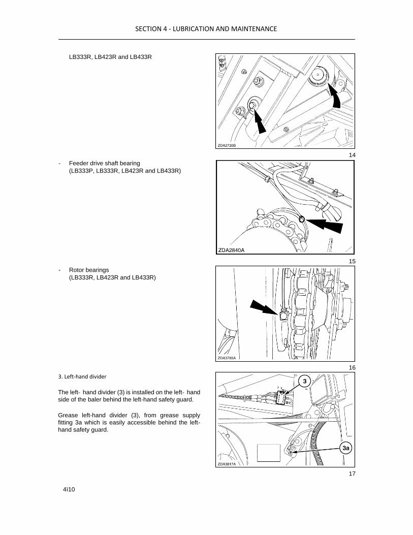
4ï10
LB333R, LB423R and LB433R
- Feeder drive shaft bearing
(LB333P, LB333R, LB423R and LB433R)
- Rotor bearings
(LB333R, LB423R and LB433R)
3. Left‐hand divider
The left‐ hand divider (3) is installed on the left‐ hand
side of the baler behind the left-hand safety guard.
Grease left-hand divider (3), from grease supply
fitting 3a which is easily accessible behind the left-
hand safety guard.
14
15
16
17

SECTION 4 - LUBRICATION AND MAINTENANCE
4ï11
Grease will be supplied to 9 grease points:
- Needle reclaim drive crank (2)
- Shuttle feeder pivot point
- Shuttle feeder roller
- Shuttle feeder top crank
- Stuffer trip mechanism
- Knotter drive output shaft
18
19
20
21

SECTION 4 - LUBRICATION AND MAINTENANCE
4ï12
4. Left‐hand knotter divider
The left‐ hand knotter divider (4) is installed on top of
the baler behind the knotter guard.
Grease left-hand divider (4), from grease supply
fitting 4a which is easily accessible from the service
platform, after opening the knotter safety guard.
Grease will be supplied to following grease points:
- 2 knotters (2 x 6)
- 2 knotters (2 x 6)
- Knotter trip mechanism (2)
22
23
24
25

SECTION 4 - LUBRICATION AND MAINTENANCE
4ï13
- Bale length metering wheel (1)
5. Right‐hand knotter divider
The right‐ hand knotter divider (5) is installed on top
of the baler behind the knotter guard.
Grease the right-hand divider (5), from grease supply
fitting (5a) which is easily accessible from the service
platform, after opening the knotter safety guard.
Grease will be supplied to
14 grease points (LB323, LB333) 22 grease points
(LB423, LB433):
- Knotters (2 x 6) or (3 x 6) (fig. 23 and 24)
- Knotter shaft central bearing
(LB423 and LB433 units only)
NOTE: Refer to page 4-5, for the full quantity of grease points.
6. Grease bank (LB323S, LB323P, LB333S, LB333P, LB423S and
LB433S)
Grease bank (6) is installed on the right‐ hand side of
the baler behind the right‐ hand safety guard.
Depending on the machine configuration, grease
bank (6) contains 2, 3 or 4 grease zerks.
26
27
28
29

SECTION 4 - LUBRICATION AND MAINTENANCE
4ï14
Grease will be supplied to the packer forks:
LB323S, LB333S: 2 packer forks
LB323P, LB333P, LB423S and LB433S: 3 packer
forks
NOTE: On a LB333P, the fourth grease zerk on grease bank (6) supplies grease to the feeder divider (refer to next paragraph headed: 7.‐Feeder divider)
7. Feeder divider (LB323P, LB333P)
The feeder divider (7) is installed on the right‐ hand
side of the baler behind the right‐ hand safety guard.
Grease the feeder divider (7), from grease zerk which
is located on the right‐ hand side on grease bank (6).
Grease will be supplied to the packer finger con rods
x6 grease points:
- Packer crank‐ shaft bearings on both sides (2) Greasing all the dividers and the grease bank (if installed) will lubricate all grease points covered by the centralised greasing system.
IMPORTANT: A blocked line or grease point can be felt while greasing as this will stall the entire divider and prevents all other grease points attached to this divider from being greased. Call for dealer assistance to fix a blocked line or grease point.
An open line can NOT be felt while greasing. Inspect all lines on a regular basis to ensure grease is reaching its destination.
30
31
32
33

SECTION 4 - LUBRICATION AND MAINTENANCE
4ï15
36
AUTOMATIC GREASING SYSTEM (if
installed)
An automatic system can be added to the existing
centralized greasing system.
1. Grease reservoir
2. Electrical grease pump (controlled by the Baler performance monitor)
3. Main divider
The electrical grease pump (2) delivers frequently
grease to main divider (3) which will distribute the
grease to the other dividers and/or grease bank of the
centralised greasing system. All grease points
covered by the centralised greasing system will be
supplied with grease during each greasing cycle.
The electrical grease pump is controlled by the baler
performance monitor to provide all grease points
frequently with a metered amount of grease: every 30
minutes at normal setting, every 45 minutes at low
setting and every 20 minutes at high setting.
With the automatic greasing system installed, it 35 remains possible to grease the different dividers and the
grease bank manually. The grease zerks to grease the dividers are still present to allow them to be used for
troubleshooting or if a fault occurs with the automatic greasing system.
NOTE: With the automatic greasing system installed it is recommended to grease the different dividers and the grease bank manually on a regular basis to get a feeling about the condition of the grease circuits.
Grease specification
Keep the 4 litres (1 US gal) grease reservoir filled with
multi purpose grease classified under NLGI Class 2.
Grease reservoir filling
WARNING Before working on the grease reservoir and to avoid
injury ensure that the relay K12 is removed. This is to
prevent the grease pump from running accidently
should the monitor and or key start be activated.
NOTE: To avoid contamination the reservoir (1) can only be filled by using the grease quick fill hand pump (2).
34

SECTION 4 - LUBRICATION AND MAINTENANCE
4ï16
To fill the reservoir using the quick fill:
1. Attach the cartridge at port and proceed as
follows:
2. Unscrew cap (3) at the grease pump and cap (4)
at the cartridge load tool.
3. Screw head (5) of the tool at the grease pump.
4. Withdraw the rod and rubber plunger of the tool
and load a cartridge with both end caps removed
in the tool (6).
5. Screw the tool with the cartridge to the grease
pump and push the grease from the cartridge into
the reservoir.
6. Remove the complete tool with the empty
cartridge and close the filler port with cap (3) (fig.
37).
CONVENTIONAL GREASE POINTS
NOTE: Grease intervals will vary as shown on the hour decals.
Grease specification
Always use grease Multi purpose grease classified
under NLGI Class 2.

SECTION 4 - LUBRICATION AND MAINTENANCE
4ï17
All points should be lubricated and then excess
grease must be wiped off. 1. Ball ring hitch (rotate ball
hitch to grease)
2. Ball hitch (optional): apply grease through the
fitting and wipe off all excess grease.
3. Stuffer clutch pawl
The grease fitting is accessible after opening the left‐hand safety guard.
4. Stuffer clutch housing
39
40
41

SECTION 4 - LUBRICATION AND MAINTENANCE
4ï18
The grease fitting is accessible after opening the left‐hand safety guard.
5. Knotter clutch pawl
The grease fitting is accessible after opening the
knotter safety guard.
6. Knotter clutch housing
The grease fitting is accessible after opening the
knotter safety guard.
7. Knife insert pivot on both sides (2 x 1)
Rotor-Cutter units only
8. Lubricate the safety needle turn buckle bearing
(one pump shot every 50 hrs)
42
43
44
45

SECTION 4 - LUBRICATION AND MAINTENANCE
4ï19
46
PTO DRIVE LINE GREASING
The baler is equipped with a 3 joint driveline. To
grease the driveline look for the grease points which
are easily identified and accessible without removal
of any covers.
IMPORTANT: Refer to the PTO manufacturer's handbook attached to the PTO shaft.
The quantity of grease to be applied varies upon the
function but in general the pumps required from the
grease gun should be sufficient enough for the grease
to extrude from the joints.
NOTE: Reccomended volume of grease at each point is as shown on the PTO decal.

SECTION 4 - LUBRICATION AND MAINTENANCE
4ï20
On the 3 joint driveline a midship bearing is fitted to
support the drive weight, and should be greased
whenever the drive line is greased.
1. PTO midship bearing
2. Knotter drive PTO, lower side (2)
The lower grease fittings are accessible after opening
the left‐ hand safety guard.
3. Knotter drive PTO, upper side
LB323, LB333 and LB433 models (1)
The grease fitting is accessible after removing the
knotter fan assembly.
LB423 models (2)
The upper grease fitting is accessible after
removing the knotter fan assembly.
48
49
50
51

SECTION 4 - LUBRICATION AND MAINTENANCE
4ï21
4. Rear wheel spindles on units with tandem
Autosteer axle on both sides (2 x 3)
FLYWHEEL
1. Flywheel with tapered bearings
The grease fitting is accessible after opening the
flywheel safety guard.
IMPORTANT: Because of the forces involved it is important to apply here at least x6 pumps of grease at every service interval.
IMPORTANT: After a shear bolt breakage ensure to regrease the bearings.
2. Stuffer gearbox drive shaft couplers x2
The grease fittings are accessible after opening the
flywheel safety guard - left‐ hand side.
3. Main drive gearbox shaft couplers
The grease fittings are accessible after opening the
flywheel safety guard - right‐ hand side.
52
53
54
55

SECTION 4 - LUBRICATION AND MAINTENANCE
4ï22
4. Jack x2
56
5. Pick-up overrun clutch
NOTE: Do not overgrease, maximum two grease gun strokes.

SECTION 4 - LUBRICATION AND MAINTENANCE
4ï23
6. Parking brake (if fitted)
7. Tandem axle centre pivot on both sides (if fitted)
57
58
59

SECTION 4 - LUBRICATION AND MAINTENANCE
4ï24
8. Brakes (where fitted)
IMPORTANT: There are several brake
configurations on these machines. Ensure you become
familiar with the grease points on your machine and
service as required. Hydraulic brakes (Rotor cutter)
Pneumatic brakes all models
Brake on axles
AUTOMATIC OILING SYSTEM
All machines are as standard equipped with an
automatic oiler system. At the operator set interval,
set from the monitor, a metered amount of oil is
supplied to the following chains:
Right-hand side:
1. Packer/rotor + pick-up drive chain
5. Dispenser
2. Pick-up main drive chain + right-hand centering auger
3. Pick-up reel drive chain + left-hand centering auger
6. Dispenser
7. Dispenser
Left-hand side:
4. Left-hand centering auger drive chain
8. Dispenser
The chains receive the pumped oil from the reservoir
through PVC tubing to small manifolds, from where
the oil is dispensed through brushes to the chains.
NOTE: The brushes are held in P clips which can be loosened to adjust the brush height to chains as they wear down.
60
61
62
63
SECTION 4 - LUBRICATION AND MAINTENANCE
4ï25
64
65
66
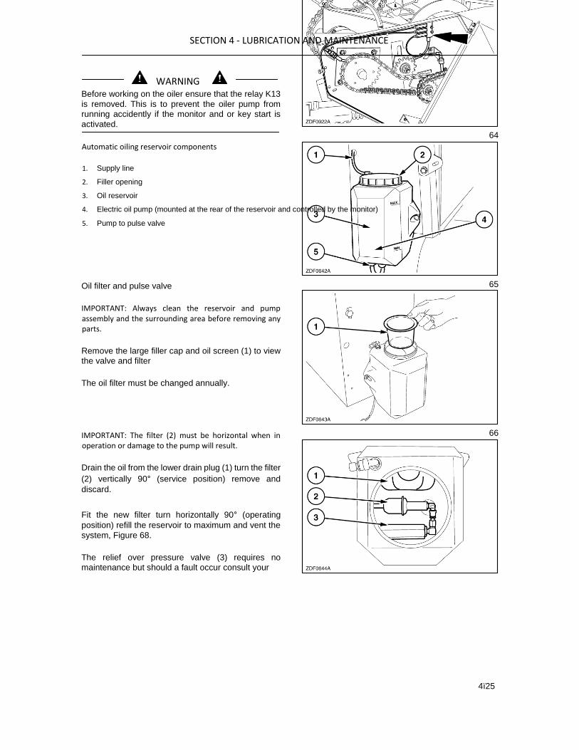
WARNING Before working on the oiler ensure that the relay K13
is removed. This is to prevent the oiler pump from
running accidently if the monitor and or key start is
activated.
Automatic oiling reservoir components
1. Supply line
2. Filler opening
3. Oil reservoir
4. Electric oil pump (mounted at the rear of the reservoir and controlled by the monitor)
5. Pump to pulse valve
Oil filter and pulse valve
IMPORTANT: Always clean the reservoir and pump assembly and the surrounding area before removing any parts.
Remove the large filler cap and oil screen (1) to view
the valve and filter
The oil filter must be changed annually.
IMPORTANT: The filter (2) must be horizontal when in operation or damage to the pump will result.
Drain the oil from the lower drain plug (1) turn the filter
(2) vertically 90° (service position) remove and
discard.
Fit the new filter turn horizontally 90° (operating
position) refill the reservoir to maximum and vent the
system, Figure 68.
The relief over pressure valve (3) requires no
maintenance but should a fault occur consult your

SECTION 4 - LUBRICATION AND MAINTENANCE
4ï26
dealer for advice. 67 Venting the oil pump
Should the oil level fall below minimum or when the oil
is drained to change the filter it will be necessary vent the oil pump to restart it.
ATTENTION: This is important do not allow the pump to run dry for more than 4 seconds at a time or it may become damaged.
Remove the left hand connection (1) and using the
monitor oil pump test (Section 2-77), run the motor in
short runs until oil is running from the hose.
68
Reconnect the hose and top up reservoir to its
maximum level. Oil specification
Keep the 5 litres (1.32 US gal) oil reservoir filled with
oil. Add oil to the reservoir through filler opening.
Use oil Ambra ISO VG 46 biodegradable or an oil
meeting the following specifications:
DIN 51524 part 2, ISO VG 46 or API CE - MIL‐ L‐2104 E.
IMPORTANT: The Ambra ISO VG 46 is a
biodegradable oil. For environmental reasons, we
recommend to use this type of oil (where available).
LINKAGES, THREADED RODS AND PIVOTS
It is recommended to oil all linkages, threaded rods
and pivot points (including guard pivot points) which
may become stiff from corrosion or dirt and after
using a pressure washer.
69

SECTION 4 - LUBRICATION AND MAINTENANCE
4ï27
MAIN DRIVE GEARBOX
Oil level
Keep the gearbox filled at all times. The oil level is
correct when it just reaches the middle of check level
indicator (1) (make sure the baler is on a level
surface).
Level indicator (1) is accessible after opening the
flywheel safety guard. When necessary, add oil
through filler port.
IMPORTANT: Always clean the filler port and the 70 surrounding area before removing the filler plug to top up or replace the oil.
Oil change
Annually or every 10000 bales.
Drain the oil through plug (3).
NOTE: Avoid spillage when draining off used oil.
Refit drain plug (3) and refill gearbox through plug (2)
to level plug (1).
Gearbox capacity
20 litres (5,3 US gal)
Oil specification
Use Ambra GEAR 135H EP with:
Viscosity grade: SAE 85W-140 or an oil meeting the
following specifications: API-GL5, MIL-L-2105 D.
71
STUFFER DRIVE GEARBOX Oil level

SECTION 4 - LUBRICATION AND MAINTENANCE
4ï28
Keep the gearbox filled at all times. The oil level is
correct when it just reaches the middle of check level
indicator (1), make sure the baler is on a level surface.
Level indicator (1) is accessible after opening the left-
hand side safety guard.
When necessary, add oil through filler port (2).
IMPORTANT: Always clean the filler port and the surrounding area before removing the filler plug to top
up or replace the oil. 72
Oil change
Annually or every 10000 bales.
Drain the oil through plug (3).
NOTE: Avoid spillage when draining off used oil.
Gearbox capacity
3.75 litres (1 US gal)
Oil specification
Use Ambra Hypoide NH520A with:
Viscosity grade: SAE 85W-140 or an oil meeting the
following specifications: API-GL5, MIL-L-2105 D
KNOTTER DRIVE GEARBOX Oil level
Keep the gearbox filled at all times. The oil level is
correct when it just reaches the middle of level
indicator (1) (make sure the baler is on a level
surface).
Level indicator (1) is accessible from the service
ladder, after opening the knotter safety guard.
When necessary, add oil through filler port (2).
IMPORTANT: Always clean the filler port and the
surrounding area before removing the filler plug to top 73 up or replace the oil. Oil change
Annually or every 10000 bales.
Drain the oil through plug (3).
NOTE: Avoid spillage when draining off used oil.
2

SECTION 4 - LUBRICATION AND MAINTENANCE
4ï29
Gearbox capacity
2.75 litres (0,7 US gal)
Oil specification
Use Ambra Hypoide NH520A with:
Viscosity grade: SAE 85W-140 or an oil meeting the
following specifications: API-GL5, MIL-L-2105 D.
BALE DENSITY HYDRAULIC CIRCUIT
General
The system uses its own hydraulic circuit which is
independent from the tractor hydraulicsystem. A
separate oil reservoir and oil filter are installed in the
baler hitch.
Oil reservoir (1) is accessible after opening the
flywheel safety guard.
Oil filter (2) is accessible underneath the baler hitch.
74
Oil level
Keep the reservoir filled at all times. The oil level is
correct when it just reaches the middle of the level
indicator (1).
IMPORTANT: Always clean the filler opening and the surrounding area before removing the filler plug to top up or replace the oil.
Oil change or top up
Annually or every 10000 bales.
A special bleeding procedure should be adhered to. Ask your dealer to do this job.
Oil capacity
Entire system: approx 4 litres (1 US gal).
Oil specification
Use Ambra HYDRAULIC FLUID BIO or a biodegradable oil meeting the following specification: DIN 51524 Part 2 HV46 or ISO VG46
Viscosity grade: 46
Oil drain
75
2
SECTION 4 - LUBRICATION AND MAINTENANCE
4ï30
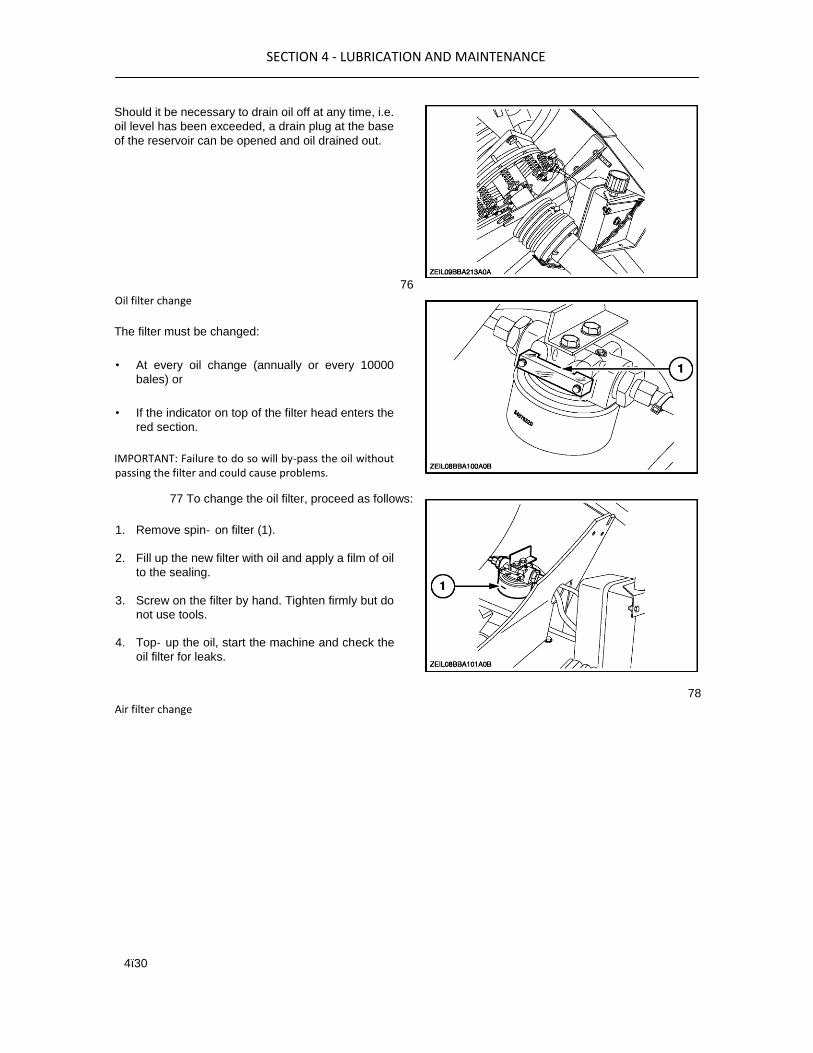
Should it be necessary to drain oil off at any time, i.e.
oil level has been exceeded, a drain plug at the base
of the reservoir can be opened and oil drained out.
76
Oil filter change
The filter must be changed:
• At every oil change (annually or every 10000
bales) or
• If the indicator on top of the filter head enters the
red section.
IMPORTANT: Failure to do so will by-pass the oil without passing the filter and could cause problems.
77 To change the oil filter, proceed as follows:
1. Remove spin‐ on filter (1).
2. Fill up the new filter with oil and apply a film of oil
to the sealing.
3. Screw on the filter by hand. Tighten firmly but do
not use tools.
4. Top‐ up the oil, start the machine and check the
oil filter for leaks.
78
Air filter change

SECTION 4 - LUBRICATION AND MAINTENANCE
4ï31
Mounted on the top of the reservoir is a filter screen.
The filter must be cleaned or changed:
• At every oil change (annually or every 10000
bales)
To change the filter (2) unscrew the cap (1) from the
filler tube (3) and discard the filter.
NOTE: To fill or top up the system, with the filter cap (1) and filter (2) removed top the oil up through the filler tube (3)
Fit a new filter and reassemble in reverse order.
CHAINS
Periodically check the sprocket alignment and chain
tension, referring to the figures below.
PACKER/ROTOR DRIVE CHAIN
LB323S, LB333S, LB423S, LB433S
The packer drive chain (1) tension is correct when
packer drive chain (1) can be deflected 20 mm (25/32
in) at (2) when applying a force of 150 N
(34 lbf).
Proceed as follows:
1. Loosen nuts at (4).
2. Adjust with bolt (3).
3. Retighten nuts at (4).
81
79
80

SECTION 4 - LUBRICATION AND MAINTENANCE
4ï32
LB323P, LB333P
The packer cutter drive chain (1) tension is correct
when the rubber damper (2) is compressed 2 mm
(5/64 in).
Adjust with nut (3).
Adjust chain guides (4) with bolts (5) to maximum 2
mm (5/64 in) from chain (1).
82
LB323R, LB333R, LB423R, LB433R
The rotor cutter drive chain (1) tension is correct when
rubber damper (2) is compressed 2 mm
(5/64 in).
Adjust with nut (3).
83
PICK-UP MAIN DRIVE CHAIN AND PICK-UP REEL
DRIVE CHAIN
LB323S, LB333S, LB333P, LB423S, LB433S
The pick-up drive chain (1) tension is correct when
pick-up drive chain (1) can be deflected 20 mm (3/4
in) at (2) when applying a force of 100 N (22 lbf).
Adjust with idler sprocket (3).
The reel drive chain (4) tension is correct when reel
drive chain (4) can be deflected 20 mm (3/4 in) at (5)
when applying a force of 100 N (22 lbf). Adjust with idler sprocket (6).
NOTE: Shield is removed for clarity.
84

SECTION 4 - LUBRICATION AND MAINTENANCE
4ï33
LB323R, LB333R, LB423R, LB433R
The pick-up drive chain (1) tension is correct when
pick-up drive chain (1) can be deflected 20 mm (3/4
in) at (2) when applying a force of 100 N (22 lbf).
Adjust with idler sprocket (3).
The reel drive chain (4) tension is correct when reel
drive chain (4) can be deflected 20 mm (3/4 in) at (5)
when applying a force of 100 N (22 lbf). Adjust with
idler sprocket (6).
NOTE: Shield is removed for clarity.
85
PICK-UP AUGER DRIVE CHAIN
LB323S, LB323P, LB333S, LB333P, LB423S, LB433S
The auger drive chain (1) tension is correct when
auger drive chain (1) can be deflected 20 mm (3/4 in)
at (2) when applying a force of 80 N (18 lbf).
Adjust with idler sprocket (3).
NOTE: Shield is removed for clarity.
86
LB323R - LB333R - LB423R - LB433R
The auger drive chain (1) tension is correct when
auger drive chain (1) can be deflected 20 mm (3/4 in)
at (2) when applying a force of 80 N (18 lbf).
Adjust with idler sprocket (3).

SECTION 4 - LUBRICATION AND MAINTENANCE
4ï34
87

SECTION 4 - LUBRICATION AND MAINTENANCE
4ï35
MAIN DRIVE
PTO DRIVE SLIP CLUTCH
All models
The slip clutch requires very little maintenance, all
that is required is the spring length setting is set and
maintained on a regular basis
To check and reset the spring insert the tang of the
special tool (identified with the torque value to match
your machine) between the two spring contact points.
Then tighten or loosen the spring retaining nut to
achieve a spring length to match the tang length.
Adjust opposite springs in a clockwise direction to
ensure all are checked and adjusted equally.
Burnishing the slip clutch
Before starting a new baling season, slip this clutch
for a few seconds.
1. Release the pressure of the friction plate by
loosening all the spring nuts slightly.
2. Block the flywheel by using the flywheel brake.
3. Engage the tractor PTO at a slow speed for a few
seconds. Stop the tractor and release the
flywheel brake.
4. Retighten all spring nuts to achieve the spring
lengths as in the table above.
Model Tool setting Spring length
LB323-S
LB323-P
LB333-S
LB333-P
Nm
(885 lbf.ft)
47.5 mm
1.87 in
LB323-R
LB333-R
LB423-S
LB433-S
Nm
(1032 lbf.ft)
45.4 mm
1.78 in
LB423-R
LB433-R
Nm
(1180 lbf.ft)
44.4 mm
1.74 in
88
89

SECTION 4 - LUBRICATION AND MAINTENANCE
4ï36
FLYWHEEL BRAKE
When the brake is activated, flywheel (1) should stop
within 12 seconds with the tractor PTO disengaged
and the machine at full speed.
If adjustment is needed, proceed as follows:
1. Loosen counter nut (2).
2. Adjust the brake by turning bolt (3). Tightening
bolts (3) will increase the braking effect and vice
versa.
90
3. Tighten nut (2).
NOTE: It is important that the flywheel is always adjusted to keep the baler from running when the flywheel brake is applied. Readjust immediately if it does not stall the baler.
PRODUCT FEEDING PICK-UP SLIP CLUTCH
The pick-up assembly is protected against overload
by a non‐ adjustable slip clutch (1).
The pick-up slip clutch (1) is set:
• At 1000 Nm (737 lbf.ft) for standard and packer
cutter units.
• At 1450 Nm (1070 lbf.ft) for rotor cutter units.
Before starting a new baling season, slip the clutch
for a few seconds to polish the friction discs.
Loosen Allen screws (1) slightly.
Turn the pick-up by hand in reverse direction to check
if the clutch is free.
ATTENTION: Wear gloves to do this job.
Turn in Allen screws (1) until there is a little tension on
the friction discs and slip the clutch for a few turns.
92
Tighten Allen screws (1).
Turn the pick-up by hand in operating direction to
check if the clutch can freewheel.
SHEARBOLTS WARNING Before attempting any repairs on the baler ensure the
Burnishing the slip clutch 91

SECTION 4 - LUBRICATION AND MAINTENANCE
4ï37
- Park brake is ON-
PTO is turned off
- The tractor engine
is turned off and
Key removed
IMPORTANT: Check why a shearbolt has failed and eliminate the cause before undertaking any repair. Always replace the shearbolts with the correct type, a different type of bolt may not shear as intended and greater damage could result. It is recommended that all three shearbolts are replaced with new after every 2500 bales.
Flywheel
Mounted behind the PTO clutch (not shown) is the
flywheel shear bolt, which protects the gearbox and
plunger. Rotate the flywheel in the opposite direction
to normal to clear any obstructions.
The shearbolt is fitted through a bush mounted in the
flywheel that can be replaced if damaged, and is
designed to protect the flywheel when the bolt shears.
IMPORTANT: If changing the bush as well ensure the bush when refitted in the flywheel is flush with the
front face of the flywheel but does not interfere with the
front hub.
93
Knotter drive
The knotter drive shearbolt protects the knotters.
needle yoke and related parts. The bolt can be
accessed from the left hand side of the baler and very
easily changed, however:
ATTENTION: It is important the knotter drive and related parts (needle to plunger timing) are reset correctly before a new bolt is fitted or serious damage could result.

SECTION 4 - LUBRICATION AND MAINTENANCE
4ï38
Refer to knotter drive shearbolt replacement,
Section 4-67. 94 Stuffer
The stuffer shear bolt mounted at the end of the arm
on the left hand side of the baler protects the stuffer
parts and generally breaks because the stuffer was
either overloaded with crop or a foreign object has
entered and blocked the stuffer arms.
IMPORTANT: Where fitted ensure the stuffer trip lock is engaged when working in the stuffer area and disengaged before baling.
The bolt can easily be accessed and repaired as and
when necessary.
IMPORTANT: Before restarting reduce the stuffer 95 trip tension one or two notches rearward on the quadrant as crop conditions may be causing the bolt to break.
SECTION 4 - LUBRICATION AND MAINTENANCE
4ï39
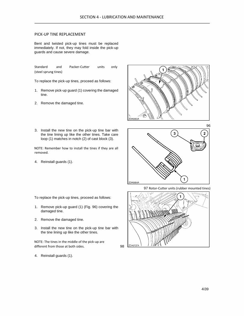
PICK‐UP TINE REPLACEMENT
Bent and twisted pick-up tines must be replaced
immediately. If not, they may fold inside the pick-up
guards and cause severe damage.
Standard and Packer-Cutter units only
(steel sprung tines)
To replace the pick-up tines, proceed as follows:
1. Remove pick-up guard (1) covering the damaged
tine.
2. Remove the damaged tine.
96
3. Install the new tine on the pick-up tine bar with
the tine lining up like the other tines. Take care
loop (1) matches in notch (2) of cast block (3).
NOTE: Remember how to install the tines if they are all removed.
4. Reinstall guards (1).
97 Rotor-Cutter units (rubber mounted tines)
To replace the pick-up tines, proceed as follows:
1. Remove pick-up guard (1) (Fig. 96) covering the
damaged tine.
2. Remove the damaged tine.
3. Install the new tine on the pick-up tine bar with
the tine lining up like the other tines.
NOTE: The tines in the middle of the pick-up are
different from those at both sides. 98
4. Reinstall guards (1).

SECTION 4 - LUBRICATION AND MAINTENANCE
4ï40
AUGER STRIPPER PLATES
On rotor cutter units, the auger stripper plates on both
sides of the pick-up are adjustable.
Adjust stripper plates (1) with bolts (2) to 1-2 mm to
auger (3) to prevent the crop from wrapping.
99
PACKER SLIP CLUTCH
The packer fingers are protected from overload by a
slip clutch.
The slip clutch needs neither adjustment nor
maintenance.
LB323S - LB333S - LB423S - LB433S
A four disc slip clutch (1), set at 2100 Nm (1550 lbf.ft),
is installed.
100
LB323P - LB333P
A six disc slip clutch (1), set at 4000 Nm (2950 lbf.ft),
is installed.
ATTENTION: It is recommended NOT to change the preset torque of this clutch as this may cause serious damage to the packer crank.
101
Burnishing the slip clutch
Before starting a new baling season, slip the clutch a
few turns to polish the friction discs.
Proceed as follows:
1. Loosen nuts (1) slightly until springs (2) are
released. Do not remove the nuts.
102

SECTION 4 - LUBRICATION AND MAINTENANCE
4ï41
2. Block the packer with a wooden block as shown.
3. Turn the flywheel by hand until the clutch slips.
4. Tighten nuts (1) (Fig. 102) to 40 Nm (29,5 lbf.ft)
torque.
103
ROTOR CUT‐OUT CLUTCH
The crop cutting rotor is protected from overload by a
cut-out clutch set at 6500 Nm (4800 lbf.ft) and cannot
be adjusted.
Grease the slip clutch every 250 hrs (two pump shots)
using the specified grease or at least a grease which
is lithium based.
NOTE: Keep the rotor drive chain tight at all times to obtain maximum performance, reliability and durability from the cut‐out clutch.
104
ATTENTION: Never attempt to modify the clutch adjustments as this will irrevocably distort the function of the cut-out clutch. Never attempt to reset the cut-out clutch with the tractor PTO engaged, as this will soon cause damage and consequently a loss of torque.
KNIFE DRAWER ADJUSTMENTS
(Rotor cutter units only)
Centering the crop cutting knives in the rotor blades
To centre the crop cutting knives, the locking plate of
the knife drawer can be adjusted.
Proceed as follows:
1. With the knife drawer closed and locked, loosen
two carriage bolts (2).
2. Centre the crop cutting knives in the rotor blades
with nut/jam nut (3) on eyebolt (4).
3. Tighten carriage bolts (2) and the nuts on the
eyebolt.

SECTION 4 - LUBRICATION AND MAINTENANCE
4ï42
105
54689

SECTION 4 - LUBRICATION AND MAINTENANCE
4ï43
Adjustment of the knife frame latching hooks
To adjust latching hooks (2) on both sides of the knife
frame, proceed as follows:
1. Retract knife frame cylinders (1) completely.
2. Loosen two carriage bolts (4).
3. Adjust latching plate (3) to latching hook (2) to a
clearance of X = 1 mm (0.04 in) with nut/jam nut (6) on eyebolt (5).
4. Tighten two carriage bolts (4) and nut/jam nut (6).
106
CUTTER KNIFE SHARPENING
Only sharp knives will guarantee optimum cutting
performance and feed capacity of the baler. Wear and
tear of the baler, as well as tractor horsepower (and
fuel) consumption raise sharply once the knives get
blunt or damaged by foreign objects.
Field test results indicate the knives can best be
resharpened after approximately 500 bales in clean
crop conditions. In contaminated crop conditions
resharpening may be necessary after 200 bales.
It is strongly recommended to have a spare set of
sharp knives available at all times, so the baling can
continue at any time whilst the used set is in the
workshop for sharpening.
Contact your dealer for offering you the service of
sharpening the knives: he may have special
equipment for a perfect job, thereby increasing the
overall lifetime of your knives.
Should you undertake to sharpen the knives yourself
by means of a portable grinding machine, observe the
following hints:

SECTION 4 - LUBRICATION AND MAINTENANCE
4ï44
• Wear gloves and safety glasses.
• Securely clamp the knife on the edge of a solid
bench.
• Grind on the smooth side of the knife only, never
on the notched side.
• Slide the machine with constant speed and equal
pressure over the full length of the cutting edge.
• Do not use grinding stone discs and certainly not
cutting discs. They do not have the correct
granulation as they self-pollute with filings and 107 produce heat.
• The best equipment is a layered, coarse grain
emery cloth disc.
• Always hold the grinder machine so that the disc
rotates away from the cutting edge of the knife. •
It is better to use a big portable grinder than a
handy-man's tool: a large size disc has less
glowing effect and will track more stable on the
knife.
STANDARD KNIVES ONLY
IMPORTANT: The following applies to standard knives only. Do not grind this front face of hard faced knives, only grind
on the back face as shown in Figure 107. • Maintain the
original bevel angle. Making the bevel flatter will not
maintain the sharp edge any longer, on the contrary;
and in stony conditions, it increases the risk of chips
breaking out of the knife.
• Do not grind each time until really all indents are
smooth. Spot damages can best be treated
individually, in this case with a handy-man small
disc tool (but also with laminated emery cloth
disc) or a round file, and from the notched side of
the knife.
• If the edge has fine burrs after sharpening, it can
be cleaned by means of a wet stone or fine file.
When reinstalling the knives, make sure they
regularly change position in the machine, i.e. middle
ones on the outside and vice versa, to equal out their
wear pattern.
55356
108
55355
109
SECTION 4 - LUBRICATION AND MAINTENANCE
4ï45
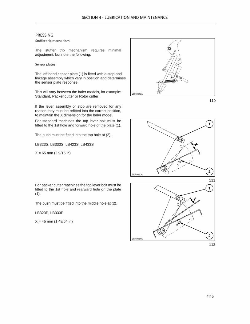
PRESSING Stuffer trip mechanism
The stuffer trip mechanism requires minimal
adjustment, but note the following;
Sensor plates
The left hand sensor plate (1) is fitted with a stop and linkage assembly which vary in position and determines the sensor plate response.
This will vary between the baler models, for example:
Standard, Packer cutter or Rotor cutter.
110
If the lever assembly or stop are removed for any
reason they must be refitted into the correct position,
to maintain the X dimension for the baler model.
For standard machines the top lever bolt must be
fitted to the 1st hole and forward hole of the plate (1).
The bush must be fitted into the top hole at (2).
LB323S, LB333S, LB423S, LB433S
X = 65 mm (2 9/16 in)
For packer cutter machines the top lever bolt must be
fitted to the 1st hole and rearward hole on the plate
(1).
The bush must be fitted into the middle hole at (2).
LB323P, LB333P
X = 45 mm (1 49/64 in)
111
112

SECTION 4 - LUBRICATION AND MAINTENANCE
4ï46
For rotor cutter machines the top lever bolt must be
fitted to the 2nd hole and lowest rearward hole on the
plate (1).
The bush must be fitted into the lowest hole at (2).
NOTE: On later machines there is only one bolt hole (2) on the rotor models.
LB323R, LB333R, LB423R, LB433R
X = 65 mm
(2.53 in)
Stuffer adjustment in the home position
Assuming the sensor plate lever and bush are fitted correctly adjust the stuffer trip setting by moving the trip plate to achieve dimension Y on the stop.
LB323S, LB333S, LB423S, LB433S
Y = 25 mm (0.97 in)
LB323P, LB333P
Y = 25 mm (0.97 in)
LB323R, LB333R, LB423R, LB433R
Y = 30 mm (1.17 in)
With the lever and bush in the correct position to
maintain dimension X, the stuffer trip set correctly to
maintain Y, you will expect to see at dimension Z be
10-14 mm (0.40-0.55 in).
If Z is not correct adjust the rod (8) which should be
All models
310 mm (12.2 in)
115
113
114

SECTION 4 - LUBRICATION AND MAINTENANCE
4ï47
STUFFER BRAKE
Stuffer brake (1) slips a certain period during each
cycle of operation. Adjust slip torque with nuts (2).
An overtightened brake will cause overheating of the
brake plates.
116
If the brake is too loose, excessive load will occur at
stuffer clutch dog (3), the stuffer fingers will not be
retained in the home position and will partially enter
the charge chamber, causing the crop to be caught.
117
The brake spring length is initially set at 35 mm (1 3/8
in). Check and adjust the brake as follows:
1. With the baler operating at normal speed, check
if the stuffer moves steadily and without abnormal
shocks.
2. Ensure that the stuffer returns and remains in the
home position. Observe the stuffer clutch after
making these adjustments and check if it is
possible to clear clutch dog arm (3) away from
roller (4) by hand.
Final adjustment:
After one hour working:
• the clutch must not overheat. If it does, reduce
the spring setting by loosening adjusting nuts (2)
(Fig. 116) half a turn.
• If the stuffer fork does not remain steady in the
home position, increase the spring setting by
tightening adjusting nuts (2) (Fig. 116) half a turn.
NOTE: Take care the three springs are adjusted equally.

SECTION 4 - LUBRICATION AND MAINTENANCE
4ï48
STUFFER FINGERS TO PLUNGER
TIMING
This timing coordinates the operation of the stuffer
drive with the operation of the plunger. To produce
well-shaped bales, it is essential to set the stuffer
fingers in relation to the plunger. The drive
mechanism shown in Figure 118 is factory set. There
should be no need to retime the baler.
Timing marks on the baler make it very easy to check
the timing. Proceed as follows:
1. Turn the flywheel until notch (1) is in line with
plate (2).
NOTE: Do not turn the flywheel in the reverse direction to obtain that plunger position.
2. At this position of the plunger, timing mark (2) on
the gearbox and the notch (1) on the clutch
should align.
118
119
120

SECTION 4 - LUBRICATION AND MAINTENANCE
4ï49
If this check indicates that the stuffer is not timed
correctly, a more precise timing procedure should be
adhered to:
1. Remove cover (1).
2. Trip the stuffer mechanism and turn the flywheel
in operating direction by hand until the tips of
stuffer fingers (1) are at a distance X = 80 mm (3
5/32 in) from the chamber knife bevel (2).
NOTE: Distance X must be obtained without turning the flywheel in reverse direction.
3. Engage the flywheel brake.
4. The plunger knife bevel (3) should be at a
distance Y = 230 - 255 mm (9 1/16 in - 10 in) from
the bale chamber knife bevel (2).
5. Disengage the flywheel brake and check if the
plunger is moving to the rear of the baler when
turning the flywheel in operating direction.
Continue to turn the flywheel until the stuffer cycle
is completed.
6. If necessary, the above described situation can
be obtained with a fairly good accuracy by
adjusting the position of half shaft coupling (1) on
splined shaft (2).
IMPORTANT: When changing this timing, note that the needles to plunger timing and the needle protection linkage adjustment will change as well. We
highly recommend this job to be carried out by your 123 dealer.
CROP HOLDING FINGERS
To check correct operation of the crop holding finger
mechanism, proceed as follows:
1. Check if the finger tips are aligned; if not, each
finger can be realigned individually by bending it.
2. Ensure that the holding finger shaft rotates freely.
121
122

SECTION 4 - LUBRICATION AND MAINTENANCE
4ï50
3. Pull the crop holding finger out of the charge
chamber until the rubber stops (2) are touching
the charge chamber. At this position, the tips of
the crop holding fingers should be flush with the
front edge of the slots in the cross beam through
which they protrude. If not, adjust rubber stops (2)
with washers (3).
NOTE: This distance should be obtained without compressing the rubber stops.
124
4. Trip the stuffer mechanism and turn the flywheel
in operating direction until cam (1) engages
5. The tips of the crop holding fingers (4) should
withdraw from the charge chamber by X = 0 to
MAXIMUM 10 mm (0 in to 3/8 in) when the roller
of linkage (2) is on the highest point of cam (1).
6. If necessary adjust X by loosening lock nut (5) on
clevis end (6). Remove the clevis pin. Rotate
clevis end (6) to shorten or lengthen holding
linkage (2) and withdraws the crop holding fingers (4) Fig. 125.
125

SECTION 4 - LUBRICATION AND MAINTENANCE
4ï51
finger arm (3) as necessary to meet the above
dimensions. Retighten lock nut (5).
7. Continue to turn the flywheel until the stuffer
returns to the home position. Crop holding fingers
(4) are now returned inside the charge chamber.
8. Ensure there is a clearance Y of approximately
10 mm (3/8 in). To adjust this clearance, loosen
nuts (8) and move rubber stop (7) on its support.
Retighten nuts (8).
STUFFER ADJUSTMENT
The stuffer movement is controlled by the profile of
the cam wheel and a gap at (X) of minimum 4.5 mm
(0.177 in) maximum 5 mm (0.197 in). This should be
maintained when lifting up the arm manually at its
home position.
When the dimension can not be maintained at (X) it
will be necessary to add shims at the buffer stop (1).
To adjust place a 5 mm (0.196 in) slip gauge between
the cam and roller at X and check the gap at the stop (1).
Any gap at (1) can be closed by loosening the nut at
(2) and sliding in slotted shims to close the gap,
retighten the nut once sufficient shims have been
inserted.
Repeat the exercise on both sides of the machine.
PLUNGER/BALE CHAMBER
Plunger rollers
The plunger is carried by four rollers. The left-hand
front roller (4) is adjustable up and down.
Observe the plunger rollers when the baler operates
at low speed to see if all four rollers rotate correctly.
in the same direction during the entire plunger stroke.
One roller should never bind by rolling against the top
of the track. If such a situation arises, adjust the
position of the front left-hand roller, as follows:
128
1. From outside the baler, loosen the bracket
hardware (3) and at (1) from the inside of the
baler rotate the eccentric plate (2) as required to
lower or raise plunger rollers, to achieve a
126
127

SECTION 4 - LUBRICATION AND MAINTENANCE
4ï52
clearance X between plunger carrier rollers (1)
and top rails (2) which should be 0.6 mm to 1.5
mm (0.030 in to 0.060 in).
2. Tighten eccentric locking bolt (1) and (3) Figure
128. Turn the flywheel by hand and observe the
plunger as described previously. Repeat step (1)
and (2) as required.
3. Check the plunger rollers again and tighten nut
(3) and bolt (1) to 240 Nm (177 lbf.ft).
After 15,000 bales, check the clearance X again
between plunger carrier rollers (1) and top rails (2)
again.
It may be necessary to insert shims at (3) between
rail and plunger frame to achieve dimension X in
which case consult your dealer for advice.
rollers, one on each side. During the entire plunger
stroke, there should be a clearance of 1 to 2 mm (0.04
in to 0.08 in) between the side roller and rail.
To adjust, loosen the roller support bolts and adjust
to the above setting.
Run the plunger several times and recheck the
setting.
130
Side roller replacement
Loosen the hardware (1) and remove the roller from
the plunger body.
Replace with a new bearing but in reverse order and
observe the settings at Figure 130, and torque nuts
(1) to 200 Nm (148 lbs ft).
131 Plunger knives to stationary knife clearance
The side tracking of the plunger is carried out by two 129

SECTION 4 - LUBRICATION AND MAINTENANCE
4ï53
The clearance between plunger knives (1) and
stationary knife (2) should be set to X = 3 mm (1/8 in).
To adjust this clearance, proceed as follows:
1. Remove plate (3) (if fitted).
2. Loosen nuts (1).
3. Add or remove shims at (2) as required.
4. Tighten nuts (1).
5. Reinstall plate (3) Figure 132 (if fitted).
ATTENTION: As rails and rollers wear, the clearance
between the knives will become smaller which may lead
to serious damage produced. Check the knife clearance
after 8,000 bales or annually and readjust when the
clearance has become 2 mm (5/64 in).
132
Plunger top, bottom and side scrapers
Always check the plunger main rollers and side rollers
adjustment before adjusting the plunger knives and
the top and side face scrapers.
• Position top face scrapers to obtain a clearance
of 8 mm (5/16 in) between the scrapers and the
bale chamber.

SECTION 4 - LUBRICATION AND MAINTENANCE
4ï54
133
SECTION 4 - LUBRICATION AND MAINTENANCE
4ï55
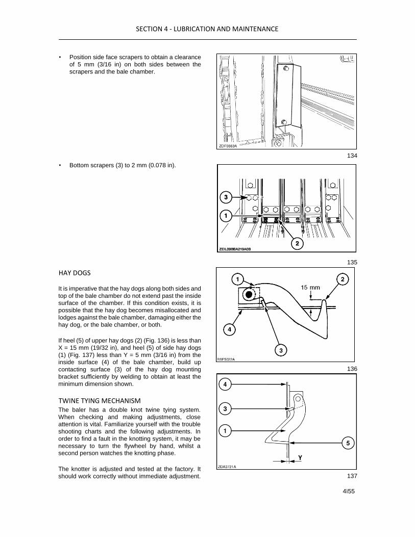
• Position side face scrapers to obtain a clearance
of 5 mm (3/16 in) on both sides between the
scrapers and the bale chamber.
• Bottom scrapers (3) to 2 mm (0.078 in).
HAY DOGS
It is imperative that the hay dogs along both sides and
top of the bale chamber do not extend past the inside
surface of the chamber. If this condition exists, it is
possible that the hay dog becomes misallocated and
lodges against the bale chamber, damaging either the
hay dog, or the bale chamber, or both.
If heel (5) of upper hay dogs (2) (Fig. 136) is less than
X = 15 mm (19/32 in), and heel (5) of side hay dogs
(1) (Fig. 137) less than Y = 5 mm (3/16 in) from the
inside surface (4) of the bale chamber, build up
contacting surface (3) of the hay dog mounting
bracket sufficiently by welding to obtain at least the
minimum dimension shown.
TWINE TYING MECHANISM The baler has a double knot twine tying system.
When checking and making adjustments, close
attention is vital. Familiarize yourself with the trouble
shooting charts and the following adjustments. In
order to find a fault in the knotting system, it may be
necessary to turn the flywheel by hand, whilst a
second person watches the knotting phase.
The knotter is adjusted and tested at the factory. It
should work correctly without immediate adjustment.
134
135
136
137

SECTION 4 - LUBRICATION AND MAINTENANCE
4ï56
If, from the outset, knot failures are experienced with
a new baler, do not readjust straight away. The failure
may be caused by the paintwork, rust or roughness.
Continue to work until the twines loosen up the
knotting parts.
Experience shows that the majority of tying difficulties
are due to poor twine tension adjustment. Before
working on the knotters, check the adjustments. After
determining the cause of a particular problem, carry
out the necessary adjustment and then check the
result on 4 or 5 bales.
The most common causes are listed below, and
should be checked before any adjustments are
carried out:
• Dirty twine tensioners (clean this area every day)
• Incorrect twine tension
• Twine tangled in twine box
• Incorrect twine routing
• Knotter parts rough or rusty (bill hook, stripper
arm, twine finger...)
• Needles out of adjustment
• Twine disc(s) out of timing, or incorrect twine disc
tension
• Twine finger(s) out of adjustment
• Incorrect adjustment of twine tensioners outside
the twine box
• Incorrect knotter adjustment
• Spring broken on lower or upper slacker arms, or
crop build-up on these arms
• Lower or upper slacker arms seized or jammed
• Twine tensioner serrated rollers worn or broken
• Twine finger(s), or twine finger shaft seized
• Hay dog(s) or spring(s) broken
• Plunger top scrapers misadjusted or broken
TWINE BREAKAGE
DANGER Serious injury may result from threading the needles
or adjusting the twine tensioners with the baler
running. The needle frame can move at any time.
Shut off the PTO and tractor engine and engage the needle safety lock prior to carrying out any repair or adjustment.
Refer to Section 3-36.
Should the twine break at any time it can easily be
corrected as follows:
Top twine
1. Clear any loose twine from the knotter area.
2. Rethread the twine as before through the rollers
and allow the loose end to drop through the
needle area and hang below the baler, or tie it to
the cross beam in line with the knotter.
Bottom twine
1. Clear any loose twine from the needle area
2. Rethread the twine as before and tie a loop in the
loose end, then hang the loop on the hook welded
to the rear of the needle frame (in line with the
tying needle) then check the result on 4 or 5
bales.
TWINE TENSION TOP Completely loosen the twine tensioners.

SECTION 4 - LUBRICATION AND MAINTENANCE
4ï57
Pull the twine (in the bale chamber or after the tucker
arm) towards you.
Increase twine tension until the slacker arm comes
down and just stays down (rests against the twine
finger shaft) while pulling twine from the twine boxes.
NOTE: Do not over tension
138
TWINE TENSION LOWER
Completely loosen the twine tensioners.
Pull the twine (in the bale chamber or after the
needle) towards you.
Increase twine tension until the slacker arm comes
and just stays up (rests against the slacker arm /
twine tensioner mounting plate) while pulling twine
from the twine boxes.
139
NOTE: Incorrect twine tension will cause several knotter malfunctions. Also, tension may change after initial break-in of components.
NOTE: The various twines available on the market are featuring different specifications in terms of size and stiffness. Therefore, pay special attention to the twine tensioner adjustment whenever changing the twine supplies.
When the second knot is formed, the quality of the
knots mainly depends on the twine tension exerted by
the lower roller tensioners.
Twine tensioner too tight: Formation of a frayed and
fragile knot.
Twine tensioner too loose: Formation of a loose knot
that can fail later on, knot ends are too short.
The knotter area should be kept clean at any time.

SECTION 4 - LUBRICATION AND MAINTENANCE
4ï58
141
DESCRIPTION OF THE KNOTTER ASSEMBLY
140
1. Knotter frame
2. Bill hook
3. Twine disc
4. Stripper arm
5. Twine knife
6. Knotter cleaner
7. Twine holder
8. Twine holder spring
9. Bill hook cam
10. Bill hook cam tension spring
NOTE: The knotter assembly shown above is the current design level, with all settings through the following knotter adjustments being applicable.
However the shape and profile of some parts shown in the adjustments section may vary slightly from the above view.
KNOTTER ADJUSTMENTS
All adjustment steps described in this section should
be performed with the baler stationary and the
knotters/needles in their home position. If necessary,

SECTION 4 - LUBRICATION AND MAINTENANCE
4ï59
remove knotter lock pins (1) and pivot each knotter
frame up.
CAUTION When pivoting the knotter up the stripper arm swings
to the right. Any person doing this without the
necessary care, will risk some severe pinching of their
fingers.
To pivot the assembly a piece of twine or a locally
fabricated tool can be used to raise the knotter.
Remove the knotter lock pin (1) shown above and lift
the knotter just enough to free the mounting lug.
Place a piece of twine (2) or a suitable tool through
the mounting hole and pull the knotter up.
CAUTION When pivoting the knotter down the stripper arm
necessary care, will risk some severe pinching of
their fingers. 142
Knotter bill hook and cam adjustment
Bill hook cam (3) operates under spring tension to
apply pressure on bill hook tongue (4) (Fig. 145) when
the knot is being formed.
The normal tension applied to billhook cam spring (1),
is by tightening the leaf spring to zero clearance until
the billhook can not be lifted manually.
If the knot comes apart or is tied so loose that it can
be pulled apart, tighten the adjusting nut slightly (1/4
turn at a time). If the knot hangs on the bill hook,
loosen the adjusting nut slightly. 143 Practical
billhook adjustment is to loosen the billhook spring nut
until the billhook opens.
Hold the billhook tongue open with your finger.
Tighten the nut until the billhook tongue just closes.
NOTE: Do not overtighten.
144

SECTION 4 - LUBRICATION AND MAINTENANCE
4ï60
Rough edges and burrs on the bill hook may cause
the knot to hang on the bill hook or cause the fibres
in the twine to be cut, thus weakening the knot. All
rough edges and burrs must be removed with a file
and then thoroughly smoothed with an emery cloth.
145
Stripper arm knife replacement
Stripper arm knife (1) must be sharp for optimum
operation of the knotter assembly.
Since plastic twine requires a sharp knife, sharpening
or replacement will be necessary occasionally. To
sharpen the knife, remove it from the stripper arm (2).
Sharpen the knife with a stone because it is made of
high carbon hardened steel. When the knife becomes
worn, replace it with a new one.
146
Stripper arm adjustment
When stripper arm (1) is actuated, half-moon shaped
notch (2) in the stripper arm flange will rub against the
heel of the bill hook (3).
A force of 40 to 60 N (9 to 13 lbf) should be necessary
to move the stripper arm flange (1) over the heel of
the bill hook (3).
147
When adjusted correctly, the notch of the stripper arm
will travel beyond the end of the bill hook with a
minimum distance X = 15-17 mm (0.59-0.66in).
In case of doubt, remove the clevis pin and swing the knotter assembly up. If a slight adjustment is necessary, it is possible to bend the stripper arm with a
hammer, pry bar, or adjustable wrench without removing any parts of the knotter. When considerable adjustment is required, it is
advisable to completely remove the stripper arm from the knotter and bend it by using a wide jaw vice.

SECTION 4 - LUBRICATION AND MAINTENANCE
4ï61
148

SECTION 4 - LUBRICATION AND MAINTENANCE
4ï62
Twine disc adjustment
The twine disc setting is determined by the position of
the notch in twine disc (1) in relation to disc cleaner
(2).
To receive the two twines, delivered by the needle,
correctly, adjust the notch in twine disc (1) to a
distance X = 2 to 3 mm (5/64 in to 1/8 in). This setting
will allow the twines to pass between the disc cleaner
and the twine holder.
If the notch in the twine disc is advanced too much
(rotated clockwise), the twine disc will not pick up 149 twine from the needle.
Retarding the notch too much (rotated counter-clockwise) can cause the twine to wrap on the bill hook shaft or the bill hook tongue to miss the twines.
To change the position of the notch in the twine disc,
proceed as follows:
1. Loosen nut (3) that secures worm gear (4).
2. Tap the nut end of the worm gear shaft lightly to
loosen worm gear (4) from the tapered worm gear
shaft.
3. Turn twine disc (1) to its recommended position,
X = 2 to 3 mm (5/64 in to 1/8 in).
4. Hold twine disc (1) so it will not move out of
position and turn the worm gear so it fits against
spacer washers (5) located between the frame
and the worm gear.
5. Tighten nut (3) on the end of the worm gear shaft
and recheck the adjustment before baling.
NOTE: Spacer washers (5) between the frame and the worm gear are provided to take any end play out of the worm gear shaft. Too many spacer washers will prevent the worm gear from seating on the taper of the worm gear shaft. Maximum allowed end play of the worm gear shaft is 0.4 mm (0,016 in).

SECTION 4 - LUBRICATION AND MAINTENANCE
4ï63
Twine holder
The function of twine holder (1) is to hold the twine in
the twine disc. Twine holder springs (2) apply
pressure to twine holder (1).
The adjustment of the twine holder should be carried
out in the field. When making an adjustment to the
twine holder tension, do not turn adjustment nut (3)
more than 1/4 turn at a time.
150
Check the knot pigtail length (1) and twine drop length
(2) from the twine holder. Both should be minimum 15
mm (19/32 in) long when this adjustment is correct.
NOTE: The twine holder adjustment should be adapted to the twine quality.
During the bill hook rotation, a small amount of twine
is needed to make the knot. This is why the twine
holder must give the possibility for the twine to slide a
little at this moment. Furthermore, some twine has to
be fed from the rear and the bottom of the bill hook.
Twine holder set too loose: The pigtails are too long,
i.e. knots are hanging on the bill hook or the knots are bow knots.
Twine holder set too tight: The pigtails are too short
and the knots are pulling loose when pressure is
applied to them.
151
KNOTTER TRIP ELECTRIC (WHERE FITTED)
WARNING Before working on the trip motor ensure that the relay
K15 is removed. This is to prevent injury should the
knotters run accidentally if the monitor and or key
start is activated.
Bale length can be set by the operator on the monitor
with this system. It is designed to complement the
existing mechanical trip (both can run together).
152
KNOTTER TRIP MECHANISM
To obtain proper functioning of the knotter cycle, it is
essential that this trip mechanism is properly
adjusted.
Knotter trip mechanism in the home position
Check the position of the clutch dog arm (1) on the
declutch cam (2). There must be an overlap X = 25-27
mm (0.98-1.062 in). If necessary:
1. Loosen lock nut (4).

SECTION 4 - LUBRICATION AND MAINTENANCE
4ï64
2. Remove the clevis pin and adjust the length of
control linkage (3) with clevis (5) to obtain the
correct overlap.
• When the linkage is shortened, the overlap is
reduced.
• When the linkage is lengthened, the overlap
is increased.
3. Install the clevis pin and tighten lock nut (4).
The length of spring (6) should be Y = 213-217 mm
(8.36-8.54 in). If necessary, adjust with nut (7).
153
Resetting the knotter trip mechanism
The trip mechanism is reset when cam (1) controls
roller (2). In this position, check the clearance
between trip arm (6) and metering roller (5). This
clearance should be
X = 3 mm (1/8 in). If necessary:
1. Loosen lock nut (4).

SECTION 4 - LUBRICATION AND MAINTENANCE
4ï65
2. Move reset roller arm (3) on the declutch arm to
meet the correct clearance X.
3. Tighten nuts (4).
ATTENTION:
• If the clearance is less than 3 mm (1/8 in), bales of uneven length will be produced.
154
•

SECTION 4 - LUBRICATION AND MAINTENANCE
4ï66
NEEDLE ADJUSTMENT
To perform or to check the adjustments listed below,
start the following steps with the needles in the home
position. Then trip the knotters manually and slowly
rotate the baler flywheel in operating direction. Needle
to bale chamber adjustment
Rotate the flywheel until needles (1) entered the bale
chamber completely.
Check that the needle feet are centered in the bale
chamber lower slots.
If not correct, loosen needle fixation bolts (3) and (4).
Move needle (2) sideways on needle mounting (1)
until it is perfectly centered in the bale chamber lower
slots.
Tighten the fixing bolts: lower nuts (3), 50-60 Nm 155
(37-44 lb ft) and upper counter nuts (4), 60-70 Nm
(44-52 lb ft).
Rotate the flywheel until the needle tips are located
under the bale chamber top slots.
Check that the top section of the needle has an
overlap to the right side of
X = 1.5 to 3 mm (0.059 in to 0.118 in).
If not correct, bend the top section of the needle, by means of a pry bar, to the right to obtain the desired
position.
NOTE: After this adjustment always perform the needle to twine disc adjustment.

SECTION 4 - LUBRICATION AND MAINTENANCE
4ï67
156
Nee
dle
to
twin
e
disc
adju
stm
ent
Rotate the flywheel until the rollers of the needle are
above the twine disc.
The clearance between the second needle roll and
the twine disc should be
X = 1.5 to 3 mm (0.059 in to 0.118 in).
If necessary, adjust distance X with fixation nuts at
the bottom end of the needle.
157

SECTION 4 - LUBRICATION AND MAINTENANCE
4ï68
To reduce this clearance, loosen nuts (4) and tighten
nuts (3).
To increase the clearance between the needle roll
and the twine disc, loosen nuts (3) and tighten nuts
(4).
Tighten the fixing bolts: lower nuts (3), 50-60 Nm (37-
44 lb ft) and upper counter nuts (4), 60-70 Nm (44-52
lb ft).
NOTE: Always check this clearance with no twine in the needles.
158
After the needles are adjusted to the bale chamber
and to the twine disc cleaner, rotate the flywheel to
perform a complete knotter cycle and check that the
needles are centered in the bale chamber lower slots,
as well as in the plunger slots. Only the top part of the
needle should rub against the right-hand side of the
bale chamber upper slots and the knotter frame.
Check the clearance between the second roller and
the twine disc cleaner.
MAXIMUM NEEDLE PENETRATION
After having completed the above adjustments, the
needle penetration should be adjusted.
Rotate the flywheel by hand until needle actuating rod
(2) intersects the centre line of the knotter shaft as
shown.
At this position, the needles are at their maximum
penetration.
Measure the distance X between the upper twine disc
and the centre of the upper needle roll. This distance
should be
X = 140 - 150 mm (5 1/2 in - 5 7/8 in).
To adjust this distance, proceed as follows:
1. Loosen nuts (4) on both sides.

SECTION 4 - LUBRICATION AND MAINTENANCE
4ï69
2. Turn needle actuating rods (2) to lengthen or
shorten the rods to obtain the correct distance X.
3. Tighten nuts 4 to 100 Nm (74 lbf.ft).
CAUTION When the maximum penetration of the needles is adjusted, always check and/or adjust the needles to plunger timing and the needle protection linkage as
described further in this section before running the baler at full PTO speed.
159
NEEDLES TO PLUNGER TIMING / KNOTTER DRIVE SHEARBOLT REPLACEMENT
The needle timing coordinates the operation of the
needle and knotter drive in relation to the plunger.
The drive mechanisms have been set ex-factory.
There should be no need to time the baler, except in
the event the knotter drive shearbolt failed.
IMPORTANT: It is recommended that all shearbolts are changed after 2500 bales.

SECTION 4 - LUBRICATION AND MAINTENANCE
4ï70
Knotter drive shearbolt replacement
In the event a knotter drive shearbolt failed, proceed
as follows:
NOTE: Timing marks on the baler drives will ease setting the baler components in the correct position before installing a new shearbolt. It is important to be accurate when matching the marks.
1. Check why the shearbolt failed and eliminate the
cause.
160
2. Turn the flywheel manually until notch (1) is in line
with plate (2).
3. Apply the flywheel brake.
161
4. Turn the knotter drive PTO shaft in the inverse
direction (counter clockwise) until timing mark (2)
on the knotter gearbox and notch (1), (middle
between the two bolts), on the clutch align
perfectly.
5. It will not be possible to install a new shearbolt
with every turn of the knotter clutch housing.
Repeat step 4 until the shearbolt can be installed
with the timing marks on the knotter drive
matching perfectly [maximum deviation between
the marks: 5 mm (3/16 in)].
6. Install the shearbolt.
162
SECTION 4 - LUBRICATION AND MAINTENANCE
4ï71
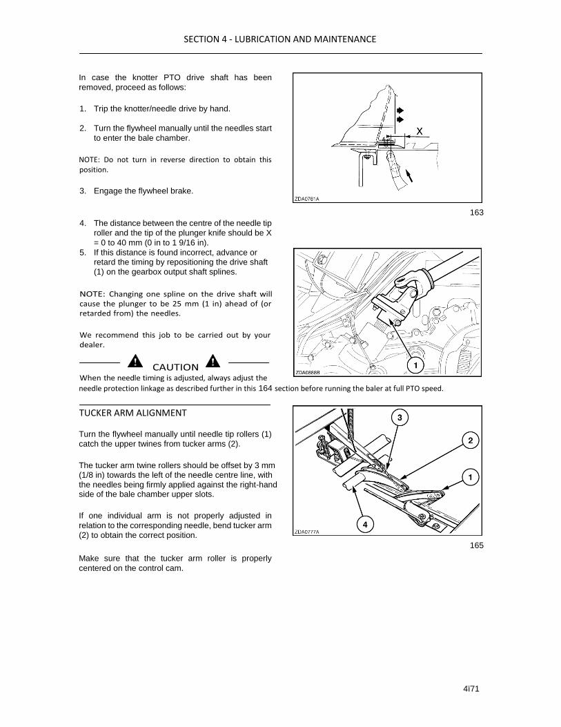
In case the knotter PTO drive shaft has been
removed, proceed as follows:
1. Trip the knotter/needle drive by hand.
2. Turn the flywheel manually until the needles start
to enter the bale chamber.
NOTE: Do not turn in reverse direction to obtain this position.
3. Engage the flywheel brake.
163
4. The distance between the centre of the needle tip
roller and the tip of the plunger knife should be X
= 0 to 40 mm (0 in to 1 9/16 in).
needle protection linkage as described further in this 164 section before running the baler at full PTO speed.
TUCKER ARM ALIGNMENT
Turn the flywheel manually until needle tip rollers (1)
catch the upper twines from tucker arms (2).
The tucker arm twine rollers should be offset by 3 mm (1/8 in) towards the left of the needle centre line, with
the needles being firmly applied against the right-hand side of the bale chamber upper slots.
If one individual arm is not properly adjusted in
relation to the corresponding needle, bend tucker arm
(2) to obtain the correct position.
165
Make sure that the tucker arm roller is properly
centered on the control cam.
5. If this distance is found incorrect, advance or retard the timing by repositioning the drive shaft
(1) on the gearbox output shaft splines.

SECTION 4 - LUBRICATION AND MAINTENANCE
4ï72
NEEDLE CARRIAGE SUPPORT
The tightening torque of four nuts (1), on both sides of
the baler must be 200 Nm (148 lbf.ft). Check this weekly.
NEEDLE BRAKE
Needle brake (1) is designed to maintain a constant
load on needle arms during the tying cycle. This load
prevents the needles from overrunning the drive and
also helps to hold the needles in the neutral position.
IMPORTANT: At the start of a season or after a time of no use, burnish the brake by slow rotation of the baler before full baling. The brake springs length (2) must be adjusted and maintained at a length of
Spring length = 26.5mm (1.04 in).
x4 springs on 3ft wide units x6 springs on 4ft wide units. If the above spring length is not sufficient, operate the baler at 540 revs min and start the knotter cycle without twine. Turn the bolts of the brake shoe sufficiently to stop the needle yoke falling down in the 2nd cycle of the knotting by its own weight, and follows the knotter clutch dog. Afterwards tighten the bolts a little more.
Brake adjustment with baler in rotation
CAUTION Before carrying out this adjustment, observe all safety precautions listed at the beginning of this manual and adjust the needle protection linkage as instructed further in this section.
To perform this check, run the baler at the rated
speed of 1000 rpm at the PTO Then trip the knotters
manually several times and check the following:
1. Test made without twines being threaded: When
the brake setting is correct, clutch arm (7) may be
lifted 0 to 5 mm (0in to 3/16 in) any time lobe (9)
passes clutch roller (8), possibly making a
clicking noise.
2. Baler in operation and after each knotting cycle:
The clicking noise possibly noticed before should
not be heard.
166
167

SECTION 4 - LUBRICATION AND MAINTENANCE
4ï73
Check the brake adjustment on a weekly basis.
If the brake is set too tight:
1. The lobe (9) on the knotter drive sprocket will
strike the clutch roller (8), causing damage to it.
2. Excessive load will be applied to drive the
knotters which could result in failure of the drive
system.
If the brake setting is too loose:
1. On the way back the needle will overrun the drive
and may cause damage to the clutch arm (7) and
trip linkage.
2. A loose brake will also allow the needle to enter
the bale chamber during the bale formation
causing repeated needle reclaims and possible
damage to the trip linkage.
3. The bale becomes too long because the tripping
mechanism does not work.
168
NEEDLE PROTECTION LINKAGE
The needle protection linkage operates in conjunction
with the plunger drive system to ensure that the
needles are removed from the bale chamber in case
of any malfunction.
To adjust, proceed as follows:
1. Check that the needle brake is properly adjusted.
2. Trip the knotter manually.
3. Turn the flywheel until a complete knotter cycle is
finished.
4. As soon as the needles start to raise, check
distance X between loop (3) and roller bearing
(4). When distance X is minimal, adjust the length
of linkage (2) with nuts (1) to obtain a distance X
= 1 to 2 mm (0.04 to 0.08 in).

SECTION 4 - LUBRICATION AND MAINTENANCE
4ï74
5. Repeat steps 2 and 3 and check again.
CAUTION Repeat this adjustment each time the needle adjustment is changed (timing, maximum penetration, needle brake).
DO NOT ADJUST the length of the protection linkage when the needle yoke is in its home position.
When the needle timing is to be adjusted, or the needle
brake setting is changed, NEVER trip the knotter at full PTO speed without PREVIOUSLY having adjusted the protection linkage as instructed above.
169
TWINE FINGERS
The twine finger positions the twine from the needle
into the path of the bill hook. It is important that the
twine fingers operate freely and are set correctly
since a large percentage of tying failures is due to
improper adjustment.
NOTE: The needles must be properly adjusted before checking the twine fingers adjustment.

SECTION 4 - LUBRICATION AND MAINTENANCE
4ï75
There are two adjustments to be considered when
checking each twine finger:
1. The clearance between the tip of the twine finger
and the needle.
2. The position of the twine finger at the end of its
stroke.
NOTE: The first adjustment must be made first since it affects the second adjustment.
To adjust the clearance between the twine finger tip
and the needle, proceed as follows:
1. Trip the knotter mechanism and rotate the
flywheel manually, observing the operation of the
twine finger and the needle.
2. When the tip of the twine finger begins to pass
the needle, the clearance between the twine
finger and the needle should be 1 to 3 mm (0.04
in to 0.12 in).
3. If necessary, loosen mounting bolts (1).
4.
5.
Move twine finger mounting (2) to the front or to the rear to set the correct clearance between the twine finger tip and needle (3).
Tighten mounting bolts (1).
170
Tucker arm alignment
The tucker arm alignment after all other adjustments
are made, should be offset 0 + 2 mm (0 + 0.078 in) to
the left at (X).

SECTION 4 - LUBRICATION AND MAINTENANCE
4ï76
171
To adjust the position of the twine finger at the end of
its stroke:
1. Turn the flywheel until the twine finger cam roller
reaches the highest point on the twine finger
control cam.
2. At this point, the inner surface of the twine finger
(1) should be perpendicular to the needle slot (2),
as shown in figure.
3. If necessary, loosen lock nut (4).
4. Remove the clevis pin.
5. Rotate clevis (5) to lengthen or to shorten rod (3)
as necessary to meet perpendicularity between
the inner surface of twine finger (1) and needle
slot (2), angle to = 90° + 5° /- 0°.
6. Install clevis pin and tighten lock nut (4).
7. Turn the flywheel to complete the knotter cycle.
172
ELECTRICAL SYSTEM
General
The following pictures and text detail service or
adjustment procedures are not to be carried out on a
routine basis.
When an electrical malfunction occurs, the procedures
listed below should help in determining and correcting the problem.
• Check that all wiring harnesses are correctly
connected.
• Check that all connector pins and sockets are
inserted correctly in the connectors.
• Check for broken or short wires.
• Check power supply and ground wires.
• Check for blown fuses.
• Refer to section Operation to fully understand the
various features and correct function. • Refer to
the Service mode in the monitor for possible error
messages (refer to section Field and site
operation, paragraph headed monitor).
Fuses and relays

SECTION 4 - LUBRICATION AND MAINTENANCE
4ï77
Fuse/relay box (1) is located on the right-hand side of
the machine.
Except for the road lights, all electrical devices on
your baler are power supplied from the fuse/relay box.
Loosen four screws (2) and remove the cover to gain
access to the fuses and relays.
ATTENTION: Be sure the box is free from dust or dirt before opening. Never operate the baler with the box
open. This to avoid dust accumulation and water 173 ingress in the box causing bad connections or shorted circuits.
Shown below is the fuse board decal located on the
fuse cover from serial number 4700.
174

SECTION 4 - LUBRICATION AND MAINTENANCE
4ï78
ATTENTION: The electrical system is designed to run all the standard equipment as recommended by the manufacturer. Do not run additional electrical equipment that requires a heavy current above normal, because overheating and damage may result. IMPORTANT: All fuses are fitted ex-factory in the fuse bank. Never replace a blown fuse with another of a different rating. When replacing a relay, make sure the new relay has the same ampere rating and the same structure (visible on the relay housing). Always use genuine parts.
NOTE: The fuse boards shown may vary slightly from 175 your machine and depends upon options fitted which determines fuses used.
Fuses in use ECU & relays in use
F1 - Main power on rail 1 fuse (30 A) -
F2 - Main power on rail 2 fuse (30 A) -
F3 - Main power on rail 3 fuse (30 A) -
F5 - Moisture and bale weight (5 A) (where fitted) ECU - Power
F8 - Proportional valve 3 A K1 - Power Rail 1
F11 - Revolving flashlight (10 A) (where fitted) K1 - Power Rail 1
F12 - Grease pump (7.5 A) K1 - Power Rail 1
F13 - Oiling (5 A) K1 - Power Rail 1
F14 - Accessory 2 (7.5 A) K1 - Power Rail 1
F15 - Bale length trip motor (7.5 A) (where fitted) K1 - Power Rail 1
F21 - Knotter fans (30 A) K2 - Power Rail 2
F22 - Accessory 1. Grease pump (5 A) (where fitted) K2 - Power Rail 2
F31 - Worklights K3 - Power Rail 3
F321 - Running lights K3 - Power Rail 3
F322 - Stuffer work light (7.5 A). Bulb 55 W (where fitted) K3 - Power Rail 3
F323 - Pick up light (7.5 A) (where fitted) K3 - Power Rail 3
SYSTEM OVERRIDE
If the main power relays are still powered:
In case the required output can not longer be
controlled by using the monitor, due to malfunctioning
of the baler controller or malfunctioning of the relay
related, the output can directly be activated by
replacing the fuse using the spares.
Proceed as follows:
1. Locate the fuse that powers the electrical device
you want to activate.
2. Remove that fuse from its original position.
3. Install the fuse in the free position of fuse bank
next to its original position.
4. The selected electrical device will be energized.
If the main power relays are not powered:

SECTION 4 - LUBRICATION AND MAINTENANCE
4ï79
NOTE: In this case the monitor will not function.
1. Change switch SW1, from its automatic position
into its manual override position.
2. Locate the fuse that powers the electrical device
you want to activate.
3. Remove that fuse from its original position.
4. Install the fuse in the free position of fuse bank
(2) next to its original position.
5. The selected electrical device will be energized.
NOTE: In both cases of overriding remember to remove the fuses again when the baler is stopped from working to avoid unnecessary electric power consumption. When the electronic system has been repaired, remember to place the fuses back in their original position on fuse bank 1. Failure to do so will result in electrical devices not being controlled from the monitor.
POWER DISTRIBUTION
When switching on the monitor, the main power
relays that are powered will be:
Main Power Relays Main relay
K1, K2 K3
These power relays will then distribute electric power
according to the chart below.
Code Circuit identification
K1 Greasing pump (where fitted)
Accessory 2
Revolving flashlight
Oiling
Bale length trip motor
K2 Knotter fans
K3 Work lights (where fitted)
ECU
Power
Moisture and bale weight (where
fitted)
ECU - PWR
SECTION 4 - LUBRICATION AND MAINTENANCE
4ï80
Knotter fans
WARNING Before working on the knotter fans ensure that the
relay K21 is removed. This is to prevent the knotter
fans from running accidently if the monitor and or key
start is activated.
IMPORTANT: Should the knotter fan fuse fail, check the rotation of the fan. If blocked by any crop spill, clear the blockage and ensure free rotation of the fan blade before fitting a new fuse.
Avoiding electrical problems
IMPORTANT: With the advancement of electrical equipment it is easy to forget the voltage, current, draw and subsequent increase in heat generation. Therefore simple routine maintenance can help prevent problems occurring.
• DO NOT add high current drain equipment to the
system other than that recommended by the
manufacturer.
• DO NOT allow dust, chaff or debris to build up in
the knotter fans. Clean with a soft brush and
ensure free rotation of the fans.
• DO NOT allow dust, chaff or debris to build up in
or around the fuse board housing.
• DO NOT allow dust, chaff or debris to build up in
or around worklamps.
• DO NOT allow loose wires or cables to get trapped
or chafe together.
• DO NOT change fuses to a higher amperage than
is already fitted by the manufacturer.
• DO NOT allow water ingress to enter electrical
connections or equipment when washing or
hosing the baler.
Sensors (digital)
Three types of sensor are used on this baler and they
are:
Twine tensioner
M12 Blue optimum gap: 1-1.5 mm (0.059-0.078 in)
Knotter gearbox
M18 yellow optimum gap: 2.5 to 3 mm.
(0.098-0.118 in)
NOTE: The sensor thread is a 1mm/turn. A good adjustment tool is to turn the head of the sensor against the tooth of the gearwheel and then turn 2.5 to 3 turns back.
All other sensors except the above
M18 black optimum gap: 3-5mm (0.118-0.196in)
NOTE: The sensor setting shown as the optimum, any settings lesser or greater than these may cause the baler to malfunction. An LED is mounted in the sensor body and will illuminate when there is no metal in the detection range. This can be checked with the ignition ON, by passing a metal object in front of the sensor.
LIGHTS‐BULB REPLACEMENT
IMPORTANT: Never replace a bulb by another with a higher power rating than indicated on the original bulb. When replacing the plastic lens, take care not to overtighten the retaining screws. Front road lights
To gain access to the light bulb, extract the two
securing screws and remove the plastic lens.
Bulb specifications: 12V 10W (DIN 72601)
Side lights

SECTION 4 - LUBRICATION AND MAINTENANCE
4ï81
To gain access to the light bulb, extract the two
securing screws and remove the plastic lens.
Bulb specifications: 12V 4W (T8/4 - HL - DIN 72601)
176
Rear road lights
To gain access to the light bulb, extract the two
securing screws and remove the plastic lens.
Bulb specifications:
1: 12V 21W (P25 - 1 - DIN 72601)
2: 12V 21W (P25 - 1 - DIN 72601)
3: 12V 10W (R19/10 - DIN 72601)
177
License plate light
To gain access to the light bulb, extract the two
securing screws and remove the plastic lens.
Bulb specifications: 12V 5W (C11 - DIN 72601)
178

SECTION 4 - LUBRICATION AND MAINTENANCE
4ï82
Working light
To gain access to the light bulb, extract the four securing
screws and remove the plastic lens.
To remove the bulb, detach the electric terminals of the
bulb and unlock spring (1).
Bulb specifications: 12V 55W (H3 - DIN 72601)
Revolving flashlight
To gain access to the bulb, remove plastic lens (1).
Bulb specifications: 12V 55W (H1 - DIN 72601)
HYDRAULIC SYSTEM
Hydraulic hose replacement
Hydraulic hoses are an important safety element in
modern machinery. However, hose characteristics
alter under pressure, thermal and UV light load over
the years. Therefore, most hoses now have a
production date printed on the metal clamp bushing
which allows to determine the age.
Legislation in certain countries and good practice
require that the hydraulic hoses are replaced when
they become 6 years old.
CAUTION Escaping fluid under pressure can penetrate the skin causing serious injury. Avoid the hazard by relieving pressure before disconnecting hydraulic or other lines. Tighten all connections before applying pressure. Protect
179
180
181

SECTION 4 - LUBRICATION AND MAINTENANCE
4ï83
hands and body from high pressure fluids. Search for leaks with a piece of cardboard.
If an accident occurs, call for a doctor immediately. Any fluid injected in the skin must be surgically removed within a few hours. If not, gangrene may result. Doctors unfamiliar with this type of injury should reference a knowledgeable medical source.
Density valve
The hydraulic density valve (1) on the left-hand side
can always be operated manually in case the
automatic or semi-manual system can not be used by
adjusting item (2).
For more information refer to Section 3 - FIELD AND
SITE OPERATION, paragraph headed Manual bale
density control.
182
WHEELS AND TIRES
Tire pressure
The life and performance of the tires depends largely

SECTION 4 - LUBRICATION AND MAINTENANCE
4ï84
upon maintaining the correct pressure. Keep the tires
inflated to the pressures given in the table.
183
Tire inflation is also shown on a decal on t he left-hand
side twine box.
184

SECTION 4 - LUBRICATION AND MAINTENANCE
4ï85
Wheel changing
1. Determine where to lift the baler with the jack (1)
under the axle and where to place the jackstand (2). The support points should be as close to the side of the baler wheel as possible.
2. Lift the wheel off the ground and let the weight of the
baler down onto the jackstand.
3. Remove the wheel nuts (1) and wheel.
NOTE: Reassemble in reverse order the wheel, tighten the nuts, re-jack, remove the stand, lower the baler, remove jack and re-torque the nuts.
Wheel nuts torque
The wheel nuts torque must be checked and torqued
correctly before using the baler for the first time.
Using a suitable torque wrench.
Do not use a hammer gun.
Torque the nuts to:
Minimum: 410 Nm (302 ft. lbs)
Maximum: 492 Nm (363 ft. lbs)
IMPORTANT: Thereafter, the nut torque must be checked and re-torqued daily during the first days of operation, then on a weekly basis until the torque of
the nuts has stabilized. If nuts become loose regularly 187 inspect and consider replacing the wheel nuts and bolts or even the wheel rim if damaged. Recheck the torques at the beginning of every new season.
BRAKE SYSTEM (WHERE FITTED)
Brake drum linings
The brake drum linings should be checked by your
local dealer annually.
Brake adjustment
185
186

SECTION 4 - LUBRICATION AND MAINTENANCE
4ï86
The aim of this adjustment is to ensure that the
wheels can turn with a minimum of resistance, whilst
maintaining maximum braking performance.
Brake adjustment should be checked frequently at
the beginning and periodically thereafter as part of a
regular maintenance schedule.
The brakes of the baler are adjusted ex-factory. After
a short bedding-in period, readjust the brakes. To
adjust the brakes proceed as follows:
1. With the brake hose connected to the tractor
braking system, depress the tractor brake pedals
to activate the braking system.
2. While keeping the pedals depressed, measure
the distance the brake cylinder(s) is (are)
extended. Then release the brake pedals.
3. If this distance is more than 60 mm (2-3/8 in),
adjust lever (1) on splined shaft (2).
188
HYDRAULIC BRAKE SYSTEM (WHERE FITTED)
The baler is equipped with one (single axle) or four
(tandem axle or tandem Autosteer axle) hydraulic
brake cylinders.
Bleeding the brake control cylinder(s)
With the brake hose connected to the tractor braking
system, depress the tractor brake pedals to activate
the braking system. While keeping the pedals
depressed, slightly release the coupler on top of the
brake cylinder(s) to bleed the circuit. Then retighten 189
the coupler and release the brake pedals.
AIR BRAKE SYSTEM (IF FITTED)
The air reservoir (1) incorporates a water bleed valve
(5) to drain any solid or liquid material that
accumulates in the air reservoir.
Bleed off regularly.
Air reservoir specification
(according to European Directive 87/404/EEC)

SECTION 4 - LUBRICATION AND MAINTENANCE
4ï87
• Trade mark: Wabco
Filter elements (4) need to be removed, cleaned or
replaced every year. When filter elements are
reinstalled, make sure the rubber seal is in place.
191
HYDRAULIC HOSE REPLACEMENT
Hydraulic hoses are an important safety element in
modern machinery. However, hose characteristics
alter under pressure, thermal and UV light load over
the years. Therefore, most hoses now have a
production date printed on the metal clamp bushing
which allows to determine the age.
Legislation in certain countries and good practice
requires that the hydraulic hoses are replaced when
they become 6 years old.
• Type: EN286-2
• Capacity: 40 litres (10.6 US gal)
• Maximum operating pressure:
14.5 bar
(210 lbf/in2)
• Maximum operating temperature:
100"C
(212"F)
• Minimum operating temperature: -50"C (-58"F)
190

SECTION 4 - LUBRICATION AND MAINTENANCE
4ï88
CAUTION Escaping fluid under pressure can penetrate the skin
causing serious injury. Avoid the hazard by relieving
pressure before disconnecting hydraulic or other
lines. Tighten all connections before applying
pressure. Protect hands and body from high-pressure
fluids. Search for leaks with a piece of cardboard.
If an accident occurs, call for a doctor immediately.
Any fluid injected in the skin must be surgically
removed within a few hours. If not, gangrene may
result. Doctors unfamiliar with this type of injury
should reference a knowledgeable medical source.
CLEANING THE BALER
1. Remove all the crop left in the machine to
facilitate cleaning.
2. Clean the interior and exterior of the baler
thoroughly because any chaff and dirt left in the
machine will attract moisture and cause rust.
NOTE:
• Avoid pressure washing at ambient temperatures below 10!C (50!F) or when the machine is wet. Place the machine in a heated workshop or dry barn for at least 24 hours, and clean it only when fully dried.
• Avoid to direct water jets onto electric equipment, bearings, seals, gearbox, oil tank filler caps.
• When using a high pressure washer spray:
- Keep a minimum distance of 30 cm (11in)
between the spray gun and the surface to be
cleaned.
- Spray under an angle of minimum 25° (do not
spray in perpendicular direction).
- Maximum water temperature: 60°C (140°F).
- Maximum water pressure: 60 bar (870 psi).
Do not use chemicals.
ACCESSORIES (WHERE FITTED)

SECTION 4 - LUBRICATION AND MAINTENANCE
4ï89
PICK-UP STOP KIT
Should it be necessary at any time to replace a hose
or repair a leak in the pick-up stop system it will
require bleeding proceeding as follows.
Bleeding the pick-up stop system.
Run the baler, with the Baler monitor ON.
In Manual operating mode, set a density pressure on the
gauge around 50 bar (725 psi).
Disengage the PTO, shut the tractor down, but
leaving the monitor under power, so the density
pressure is maintained in the system.
Disconnect the hydraulic hose elbow at the cylinder port
and have a clean oil can to catch the oil.
On the monitor, select the ”Service mode”, ”Diagnostics Output”, ”Pick-up stop”, select ”Digital” read-out.
Switch the valve ON and back OFF until the hydraulic
hoses are filled with oil.
Reconnect the elbow to the cylinder, switch the valve ON
and OFF until the oil is free from air bubbles.
Tighten the elbow at the cylinder and switch the monitor
off.
Top up the hydraulic oil reservoir with the lost oil.
194 BALE WEIGH SYSTEM - CALIBRATION
NOTE: To do this calibration the machine has to be equipped with the software version 3.6.8.0 or later, the bale weighing system with the software 1.2.0.0 or later.
There are two calibrations that need to be done, if
both need to be done start with the calibration of the
Accelorometer.
192
193

SECTION 4 - LUBRICATION AND MAINTENANCE
4ï90
NOTE: Before starting the calibrations switch on the machine electrical system for minimum 15 minutes to warm up the electronics. Perform the calibration of the load cells within 60 minutes.
1. Accelero-meter
1. Place the machine on a horizontal flat ground
with the rear part of the roller bale chute open in
a lateral horizontal position using the machine
hydraulic system.
NOTE: Refer to operation in this manual.
2. In the monitor, select ”Diagnosis inputs”.
NOTE: Refer to operation in this manual.
3. Select the ”bale weight system”.
195
4. Enter the calibration mode by selecting again
”Diagnosis inputs” button
196
5. Select the Accelerometer button (AJ) to start the
calibration.
197
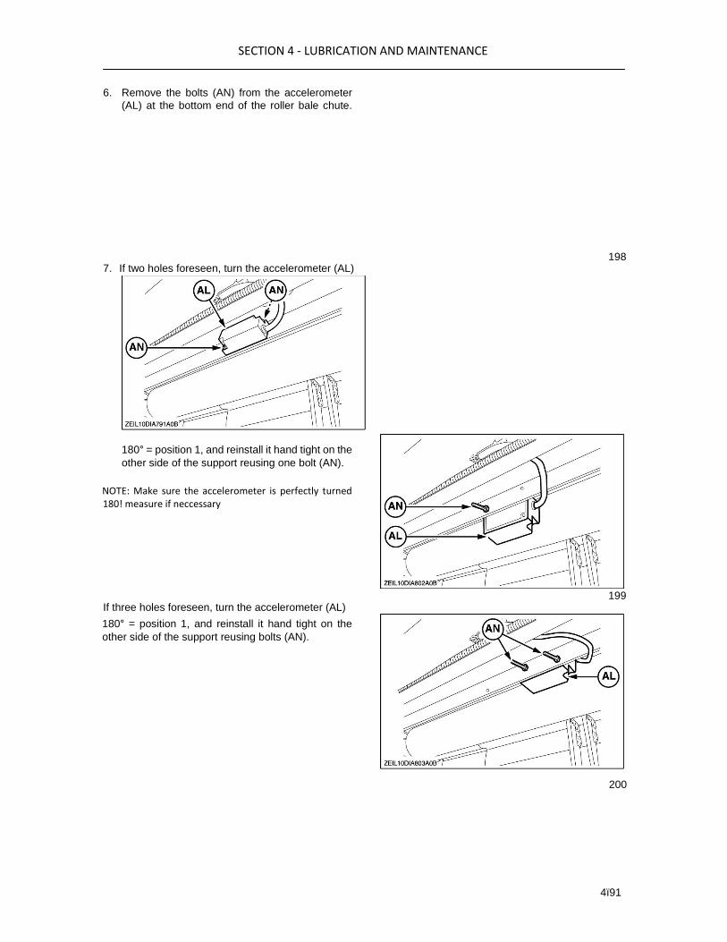
SECTION 4 - LUBRICATION AND MAINTENANCE
4ï91
6. Remove the bolts (AN) from the accelerometer
(AL) at the bottom end of the roller bale chute.
180° = position 1, and reinstall it hand tight on the
other side of the support reusing one bolt (AN).
NOTE: Make sure the accelerometer is perfectly turned 180! measure if neccessary
180° = position 1, and reinstall it hand tight on the
other side of the support reusing bolts (AN).
200
7. If two holes foreseen, turn the accelerometer (AL) 198
If three holes foreseen, turn the accelerometer (AL) 199

SECTION 4 - LUBRICATION AND MAINTENANCE
4ï92
8. Confirm the position 1 by selecting the green V
mark button (AI).
9. The calibration will start and takes a few seconds
the status ”busy” will appear on the screen. Wait
at this time.
NOTE: Do not move the roller bale chute during calibration.
201
10. When this screen appears, loosen the bolts (AN).
Turn the accelerometer (AL) and reinstall it in its
original place = position 2, reusing the bolts (AN).
11. Confirm the position 2 by selecting the green
Vmark button (AI).
the status ”busy” will appear on the screen. Wait
at this time.
NOTE: Do not move the roller bale chute during calibration.
13. When the status ”Calibration done” appears, the
second value is saved and the date will be
entered. This calibration is now done.
203
2. Load cells
1. Place the roller bale chute in the normal working
position.
NOTE: Refer to operation in this manual.
2. At the bottom of the bale weighing frame (1) there
are two brackets (AR) through which you can fit a
bar (AS).
3. Have three calibration weights (AU) at hand with
a weight including the bar (AS) and the support
(AT) if necessary. 204
12. The calibration will start and takes a few seconds, 202

SECTION 4 - LUBRICATION AND MAINTENANCE
4ï93
Low weight 80-100 kg (176.4-220.5 lb)
Medium weight 200-300 kg (440.9-661.4)
High weight 400-500 kg (882-1102 lb)
NOTE: Weigh the three weights separately (up to one decimal) exactly on a balance. The exactness of the value of the weights determines the precision of the system.
4. In the monitor, select ”Diagnosis inputs”.
NOTE: Refer to operation in this manual.
5. Select ”bale weight system”.
205
6. Enter the calibration mode by selecting again the
”diagnosis inputs” button.
206
7. Select the weight field (AK).
207

SECTION 4 - LUBRICATION AND MAINTENANCE
4ï94
8. Fill in the weight of the ”low weight”, the ”medium
weight”, and the ”high weight” you have at hand
using the numeric key pad.
9. Select the weight button (AL) to start the 208
calibration.
10. Confirm the weights you have already entered by 209
selecting the green V mark (AI).
210
11. When this screen appears, remove the
”lowweight” on the bar (AS).
NOTE: Hang the weights free in the middle of the roller bale chute, do not move the chute anymore.
12. Select the green V mark button (AI), at the screen
with the status ”busy” will appear, wait at this
moment.
211

SECTION 4 - LUBRICATION AND MAINTENANCE
4ï95
13. When the screen appears, remove the
”lowweight” and hang the ”medium weight” on the
bar (AS).
NOTE: Hang the weights free in the middle of the roller bale chute, do not move the chute anymore.
14. Again select the green V mark button (AI) on
thescreen with the status ”busy” will appear, wait
at this moment.
weight” and hang the ”high weight” on the bar
(AS).
NOTE: Hang the weights free in the middle of the roller bale chute, do not move the chute anymore.
16. Again select the green V mark button (AI) on
thescreen with the status ”busy” will appear, wait
at this moment.
213
17. The calibration was performed succesfully
whenthe status ”Calibration done” appears, the
values are saved and the date will be entered.
18. Remove the weights and the bar (AS) from
thebale frame.
19. Test the bale weighting systemNOTE: Refer to
operation in this manual.
BALE LENGTH KIT ELECTRIC
CALIBRATION
Select the "Field setting" icon (S) on the "Main screen"
in the monitor.
214
15. When the screen appears, remove the ”low 212

SECTION 4 - LUBRICATION AND MAINTENANCE
4ï96
Put the "Bale length" and "Measured bale length" on the same value using the numeric keypad.
Take the mean value of those bales and fill in that
value in the "Measured bale length" field using the
numeric keypad. Now the calibration is done.
216
DIAGNOSTIC INPUTS
Inputs from sensors and other sources can be
displayed, which are used for Dealer guidance and
correction.
These inputs can be viewed through the error
overview screen by selecting the diagnosis input icon
and screen. Follow the on screen prompts where
displayed.
Example of input items that can be checked, and if
sensor controlled can be adjusted:
Make five bales and measure their separate lengths. 215
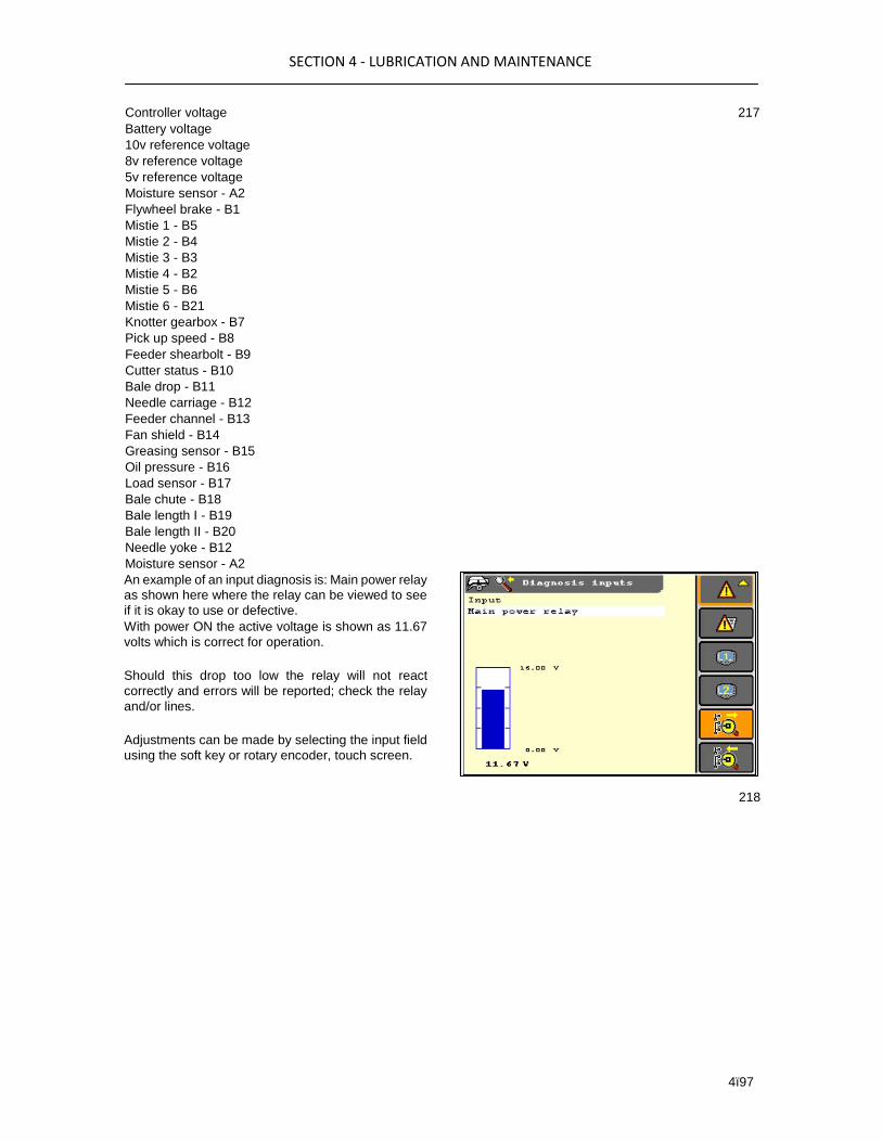
SECTION 4 - LUBRICATION AND MAINTENANCE
4ï97
Controller voltage
Battery voltage
10v reference voltage
8v reference voltage
5v reference voltage
Moisture sensor - A2
Flywheel brake - B1
Mistie 1 - B5
Mistie 2 - B4
Mistie 3 - B3
Mistie 4 - B2
Mistie 5 - B6
Mistie 6 - B21
Knotter gearbox - B7
Pick up speed - B8
Feeder shearbolt - B9
Cutter status - B10
Bale drop - B11
Needle carriage - B12
Feeder channel - B13
Fan shield - B14
Greasing sensor - B15
Oil pressure - B16
Load sensor - B17
Bale chute - B18
Bale length I - B19
Bale length II - B20
Needle yoke - B12
Moisture sensor - A2
217
An example of an input diagnosis is: Main power relay
as shown here where the relay can be viewed to see
if it is okay to use or defective.
With power ON the active voltage is shown as 11.67
volts which is correct for operation.
Should this drop too low the relay will not react
correctly and errors will be reported; check the relay
and/or lines.
Adjustments can be made by selecting the input field
using the soft key or rotary encoder, touch screen.
218

SECTION 4 - LUBRICATION AND MAINTENANCE
4ï98
Another example of inputs could be Misties, when the
signal is not correct which case repair the fault or
change the sensor.
Where a new sensor is fitted adjust as discussed in
”Sensor adjustment” move the sensor in or out to
achieve the correct reading.
As in the case of the optional bale length system
which can be checked in the same way and
adjustments made, by selecting the input field using
the soft key or rotary encoder, touch screen.
219
220

SECTION 4 - LUBRICATION AND MAINTENANCE
4ï99
DIAGNOSTIC OUTPUTS
Outputs for solenoids and other sources can be
displayed, which are used for Dealer guidance and
correction.
NOTE: Relay output is only possible when the output is in off state. In the on state it is not possible.
Not possible also for the density valve and pick-up stop since they are directly controlled by the processor board (not relays).
These can be viewed through the error overview screen using the diagnosis output icon.
Shown below are examples of outputs that can be
checked, by selection of the switch ICON (1). For
example in this screen and with operating lights
selected, these can be switched On and OFF using
the monitor.
221
Main power relays - K1, K2
Main power relay - K3
Knotter fans - K21
Flashing light - K11
Operating lights - K31
Grease pump - K12
Accessory 2 - K14
Density valve - Y2
Chain oiling pump - K13
Pickup stop (where fitted) - Y4
Bale electric trip system (where fitted) - K15
Stuffer light - K31
Density sensor - Y2 222
Bale weigh system (where fitted)

