servovalves series bd, ph, se - '+domain name+' · and valve current as shown in figure...
TRANSCRIPT

Catalogue HY11-3292/UKNovember 2003
ServovalvesSeries BD, PH, SE

2
Servovalves.PM6.5 CM
Parker Hannifin GmbHHydraulic Controls DivisionKaarst, Germany
Catalogue HY11-3292/UK
NoteThis document and other information from Parker HannifinGmbH, its subsidiaries, sales offices and authorizeddistributors provide product or system options for furtherinvestigation by users having technical expertise. Before youselect or use any product or system it is important that youanalyse all aspects of your application and review theinformation concerning the product or system in the currentproduct catalogue. Due to the variety of operating conditionsand applications for these products or systems, the user,through his own analysis and testing, is solely responsiblefor making the final selection of the products and systemsand assuring that all performance and safety requirementsof the application are met. The products are subject tochange by Parker Hannifin GmbH at any time without notice.

3
Servovalves.PM6.5 CM
Parker Hannifin GmbHHydraulic Controls DivisionKaarst, Germany
Catalogue HY11-3292/UK
Series Description Page
BD15/BD30 Characteristics 5Technical Data 5Ordering Code 6Characteristic Curves 7Dimensions/Wiring 8Accessories 10
PH76 Characterisics 11Technical Data 11Ordering Code 12Characterisic Curves/Wiring 13Dimensions 14
SEMT Characterisics 15Technical Data 15Ordering Code 16Characterisic Curves/Wiring 17Dimensions 18
SE05/SE10/SE15 Characteristics 19Technical Data 19Ordering Code 20Characteristic Curves 21Characteristic Curves/Wiring 22Dimensions 23Technical Information 24
SE2N Characteristics 25Technical Data 25Ordering Code 26Characteristic Curves/Wiring 27Dimensions 28
SE20 Characteristics 29Technical Data 29Ordering Code 30Characteristic Curves 31Characteristic Curves/Wiring 32Dimensions 33
SE2E Characteristics 35Technical Data 35Ordering Code 36Characteristic Curves 37Dimensions 38Wiring 39
SE31 Characteristics 41Technical Data 41Ordering Code 42Characteristic Curves/Wiring 43Dimensions 44
SE60 Characteristics 47Technical Data 47Ordering Code 48Characteristic Curves/Wiring 49Dimensions 50
ContentsServovalves

4
Servovalves.PM6.5 CM
Parker Hannifin GmbHHydraulic Controls DivisionKaarst, Germany
Catalogue HY11-3292/UK
Notes

5
Servovalves.PM6.5 CM
Parker Hannifin GmbHHydraulic Controls DivisionKaarst, Germany
Catalogue HY11-3292/UK
General Description
The BD Series servo valves provide high resolution inthe control of position, velocity and force in motion con-trol applications.
Features
• Rugged reliable trouble-free operation• Reduced contaminant sensitivity• Linear flow gain characteristics• Intrinsically safe model available• Explosion proof model available
OperationWhen used in conjunction with our BD90/95 series ofservo amplifiers or our PMC series of motion controllers,the BD series of valves will provide accurate control ofrotary and linear actuators.
Specifications
Flow Rating ± 10%(at 70 bar) [l/min] 3.78 to 151Pressure Ranges [bar] 0-207, 14-45, 48-66, 69-90
97-135, 138-173, 179-207Quiescent flow BD15 [l/min] 1.5-2.1(Std. spool lap) BD30 [l/min] 2.1-3.78Non-linearity [%] ≤ 5Hysteresis [%] ≤ 3Threshold [%] ≤ 0.5Null Shift
with temperature [%] < ±2 per 38°Cwith pressure [%] < 2 per 69 bar
Pressure Gain % changein presure per 1% change in 30% typicalinput commandStep response BD15 10 - 90%, 26 ms
BD30 10 - 90%, 30 msFluid Mineral Oil, 60 to 225 SSU
1000 SSU maximumFluid cleanliness SAE Class 3 or better,
ISO Code 15/12Operating temp. [°C] -1 to +106Protection class NEMA 1, IP54
CharacteristicsServovalvesSeries BD
Flow-Load CharacteristicsControl flow to the load will change with load pressureand valve current as shown in figure 1.
These characteristics closely follow the theoreticalsquare-root relationship for sharp-edged orifices as il-lustrated in the equation below.
Q = K √ ∆P
Q = Control flow, cubic inches/sec
K = Valve constant
∆P = Valve pressure drop
Quick Reference Data Chart
Model Flow Capacity Max. Pressure Max. Tank Port Electrical input Coil resistance Weight(l/min) Rating Pressure Circle (Std.) Single Coil (Std.) Each Coil
BD15 3.8, 9.5, 19, 37, 57, 76 210 bar 14 bar 0.875 60 mA (full flow) 60 Ohms 1.2 kg
BD30 76, 95, 113, 151 210 bar 14 bar 1.75 60 mA (full flow) 60 Ohms 2.9 kg
* for optimum performance, Parker Servo Valves are designed tooperate within specific system supply pressure ranges.
Change in flow with current and load pressure

6
Servovalves.PM6.5 CM
Parker Hannifin GmbHHydraulic Controls DivisionKaarst, Germany
Catalogue HY11-3292/UK
Ordering Code
BD
Series Connector 2) Seals FlowSupplypressure
Size Options Coils
Code
ABCDEFGHJ1)
K
(mA) Ohms
3.615.211.87.35.54.52.21.1
3.5/3.52.9
60 (Std.)1520304050
100200
30/3080
voltage
60101659124313890225.7
118/11836
Code
ABCDJL
BD15
C2B (Std.)C2DC1BC1D
Intrinsic SafeExplosion Proof
Code
N
V
Seals
Nitrile (Std.)
Fluorocarbon
ServovalvesSeries BD
Code
1530
Code
A
B
C
J
N
Options
Standard Valve
Intrinsic Safe
Explosion ProofFM Approved
Explosion ProofCSA Approved
Explosion ProofATEX Approved
Code
B
C
D
E
F
G
H3)
Supply pressure
179 to 207 bar
138 to 173 bar
97 to 135 bar
69 to 90 bar
48 to 66 bar
14 to 45 bar
0 to 207 bar(5th Port)
EFGHKM
BD30
C2B (Std.)C2DC1BC1D
Intrinsic SafeExplosion Proof
Code
12.55
101520
Flow BD15 (l/min)
3.89.519385776
Code
20253040
Flow BD30 (l/min)
7695
113151
1) For intrinsic safe only.
2) Connector Location and Flow Polarity(Standard connector over C
2, + to B = P to C
1 flow)
C2B = Connector over Port C2, + to Pin B = P to C1 flow.
C2D = Connector over Port C2, + to Pin D = P to C1 flow.
C1B = Connector over Port C
1, + to Pin B = P to C
1 flow.
C1D = Connector over Port C
1, + to Pin D = P to C
1 flow.
3) Supply Pressure: Code “H“ applies to 5th Port/External Pilot Option. Thisrequires the use of a blank orifice “–00”. First stage pressure should be lim-ited to 400 PSI and no less than 250 PSI.Pressures in excess of 600 PSI may damage pilot.
1) for intrinsic safe only
Size Capacity
3.8 up to 7676 up to 151

7
Servovalves.PM6.5 CM
Parker Hannifin GmbHHydraulic Controls DivisionKaarst, Germany
Catalogue HY11-3292/UK
Characteristic CurvesServovalvesSeries BD15 and BD30
Typical Response Curves
BD15
Pressure Drop Curves
BD15
BD30
BD30
BD15 Typical FrequencyResponse at ±25% Input Current
BD30 Typical FrequencyResponse at ±25% Input Current
8
Servovalves.PM6.5 CM
Parker Hannifin GmbHHydraulic Controls DivisionKaarst, Germany
Catalogue HY11-3292/UK
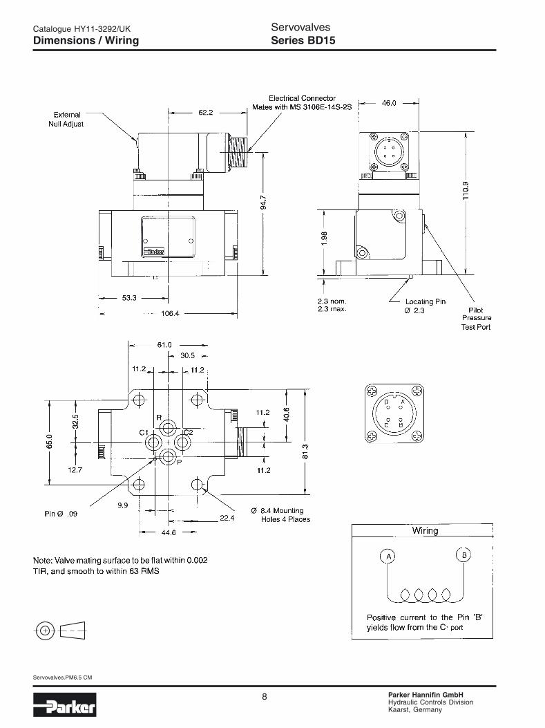
Dimensions / WiringServovalvesSeries BD15
9
Servovalves.PM6.5 CM
Parker Hannifin GmbHHydraulic Controls DivisionKaarst, Germany
Catalogue HY11-3292/UK
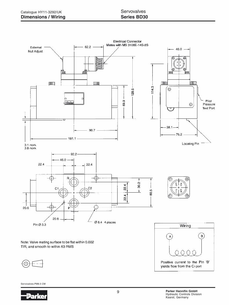
Dimensions / WiringServovalvesSeries BD30
10
Servovalves.PM6.5 CM
Parker Hannifin GmbHHydraulic Controls DivisionKaarst, Germany
Catalogue HY11-3292/UK
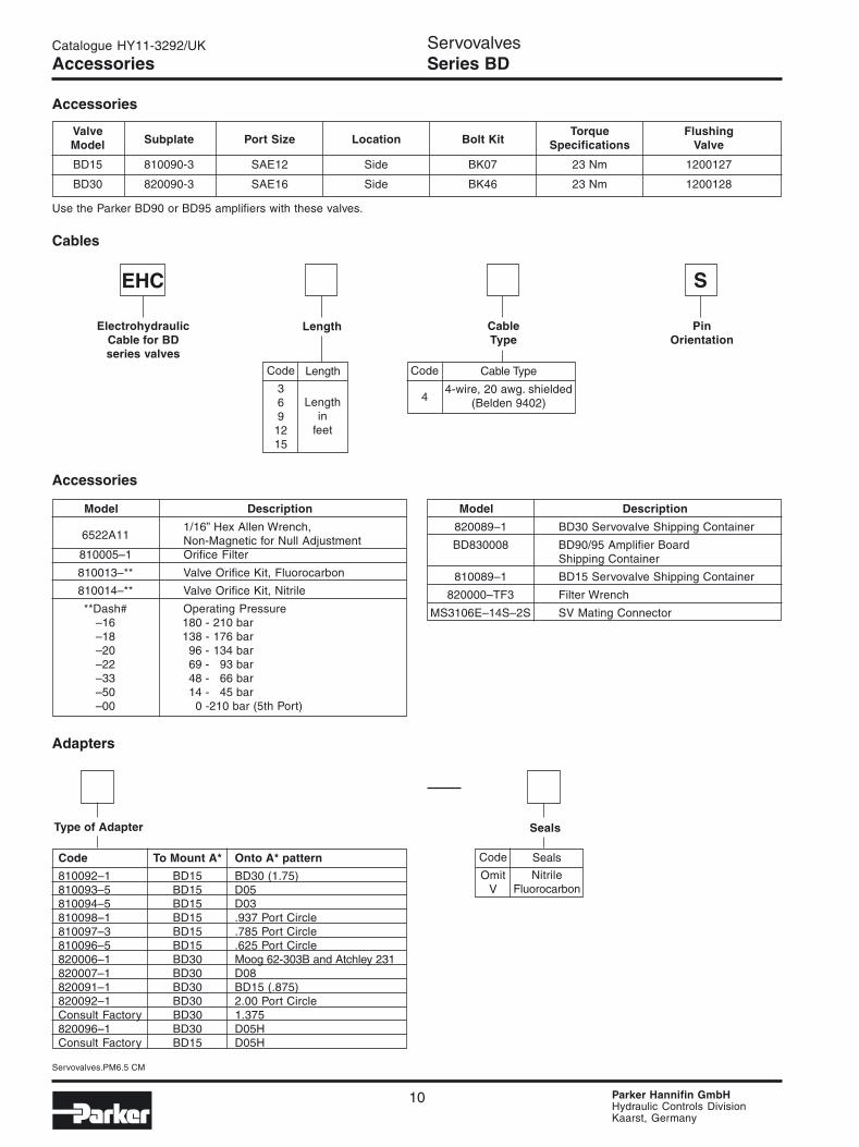
AccessoriesServovalvesSeries BD
ValveSubplate Port Size Location Bolt Kit
Torque FlushingModel Specifications Valve
BD15 810090-3 SAE12 Side BK07 23 Nm 1200127
BD30 820090-3 SAE16 Side BK46 23 Nm 1200128
Accessories
Use the Parker BD90 or BD95 amplifiers with these valves.
Cables
EHC
ElectrohydraulicCable for BDseries valves
Length CableType
PinOrientation
Code
4
Cable Type
4-wire, 20 awg. shielded(Belden 9402)
Code
369
1215
Length
Lengthin
feet
Model Description
6522A111/16” Hex Allen Wrench,Non-Magnetic for Null Adjustment
810005–1 Orifice Filter
810013–** Valve Orifice Kit, Fluorocarbon
810014–** Valve Orifice Kit, Nitrile
**Dash# Operating Pressure–16 180 - 210 bar–18 138 - 176 bar–20 96 - 134 bar–22 69 - 93 bar–33 48 - 66 bar–50 14 - 45 bar–00 0 -210 bar (5th Port)
Model Description
820089–1 BD30 Servovalve Shipping Container
BD830008 BD90/95 Amplifier BoardShipping Container
810089–1 BD15 Servovalve Shipping Container
820000–TF3 Filter Wrench
MS3106E–14S–2S SV Mating Connector
Adapters
Type of Adapter Seals
Code
OmitV
Seals
NitrileFluorocarbon
Code To Mount A* Onto A* pattern
810092–1 BD15 BD30 (1.75)810093–5 BD15 D05810094–5 BD15 D03810098–1 BD15 .937 Port Circle810097–3 BD15 .785 Port Circle810096–5 BD15 .625 Port Circle820006–1 BD30 Moog 62-303B and Atchley 231820007–1 BD30 D08820091–1 BD30 BD15 (.875)820092–1 BD30 2.00 Port CircleConsult Factory BD30 1.375820096–1 BD30 D05HConsult Factory BD15 D05H
Accessories
S

11
Servovalves.PM6.5 CM
Parker Hannifin GmbHHydraulic Controls DivisionKaarst, Germany
Catalogue HY11-3292/UK
General Description
The PH76 servovalves are high performance, two stagevalves, with a range of rated flows from 3.8 to 57 l/min.The pilot stage is a symmetrical double-nozzle and flap-per, driven by a double air gap, dry torque motor. A lowcurrent signal to the torque motor pilot stage results in aproportional flow from the output stage. The output stageis a 4-way, sliding spool which provides a mechanicalfeedback using an exclusive “no ball glitch” design.
Features
• Built to survive tank port pressure spikes• No ball glitch• Tool steel spool and body• Optional 5th port for external pilot• ISO 10372 standard 22.23 mm port circle
Specifications
Flow Rating ± 10%(at 70 bar) [l/min] 3.8, 9.5, 19, 28, 38, 57Supply pressure [bar] 10 - 210Tank port pressure [bar] max. 210
< 10 for best performanceNull leakage flow(at 70 bar) [l/min] 0.2 - 0.8Pilot flow(at 210 bar) [l/min] 0.8 - 1.2Input command [mA] ±50 std.Frequency response > 90(at 90° phase shift) [Hz] (see Performance Curves)Non-linearity [%] ≤ 10Hysteresis [%] ≤ 4Threshold [%] ≤ 0.5Null shift with temperature [%] ≤ 2 per 55°C
with pressure [%] ≤ 2 per 70 barPressure gain % changein pressure per 1% change in 30% minimum,input command 70% maximumStep response 0 - 100%, < 15 msFluid Mineral Oil, 60 to 225 SSU
1000 SSU maximumFluid cleanliness ISO 4406 15/12 or betterOperating temp. [°C] -1 to +82Protection class NEMA 4, IP65
CharacteristicsServovalvesSeries PH76
Performance Curves
Servovalve flow is proportional to the square root of thepressure drop through the valve. The nominal flow ratingfor the servo-valves is based upon a 70 Bar (1000 PSI)pressure drop.
Flow vs. pressure dropat 100% commandFlow Path P→C1→C2→R
12
Servovalves.PM6.5 CM
Parker Hannifin GmbHHydraulic Controls DivisionKaarst, Germany
Catalogue HY11-3292/UK
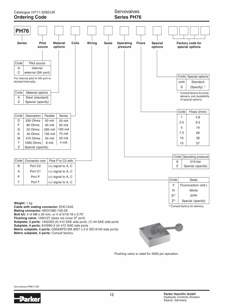
Ordering Code
PH76
Series Wiring Seals Specialoptions
Factory code forspecial options
Flows
Code
omit
S
Special options
Standard
(Specify) 1)
Pilotsource
Materialoptions
Coils Operatingpressure
Code
DFGKMTZ
Description Parallel
25 mA20 mA
100 mA75 mA20 mA4 mA
200 Ohms80 Ohms22 Ohms40 Ohms
475 Ohms1000 Ohms
Series
50 mA40 mA200 mA150 mA40 mA8 mA
Code
B
A
P
T
Connector over Flow P to C2 with:
(+) signal to A, C
(+) signal to A, C
(+) signal to A, C
(+) signal to A, C
Port C2
Port C1
Port P
Port T
1) Consult factory for price,delivery and availabilityof special options.
Code
1
2.5
5
7.5
10
15
Flows (l/min)
3.8
9.5
19
28
38
57
Code
V
N
E2)
Z2)
Seals
Fluorocarbon (std.)
Nitrile
EPR
Special (specify)
ServovalvesSeries PH76
Code
AC
Pilot source
internalexternal (5th port)
Code
AZ
Material options
Steel (standard)Special (specify)
For internal pilot th 5th port isblocked internally.
Special (specify)
Code
AZ
Operating pressure
210 barSpecial (specify)
2) Consult factory for deliveryWeight: 1 kgCable with mating connector: EHC154SMating connector: MS3106E-14S-2SBolt kit: 4 of M8 x 20 mm, or 4 of 5/16-18 x 0.75”Flushing valve: 1200127 (does not cover 5th port)Subplate, 5 ports: 1402303 (4) #12 SAE side ports, (1) #4 SAE side portsSubplate, 4 ports: 810090-3 (4) #12 SAE side portsMetric subplate, 4 ports: DS04SPS12M (M27 x 2.0 ISO 6149 side ports)Metric subplate, 5 ports: Consult factory.
Flushing valve is rated for 3000 psi operation.

13
Servovalves.PM6.5 CM
Parker Hannifin GmbHHydraulic Controls DivisionKaarst, Germany
Catalogue HY11-3292/UK
Step response at 210 bar
4 - 60 l/min
Frequency Response
The frequency response curves for the PH76 servovalvesshow no significant change for signal amplitudes between±10% and ±40%. Frequency response is unaffected bychanges in supply pressures above 70 bar.
Polarity shown connects flow from P to C2 port.
Characteristics Curves/WiringServovalvesSeries PH76
Installation Wiring Options
The PH76 servovalve has two coils. One is wired across pins A to B, the other across pins C to D. When connectingthe valve to a drive amplifier, the user's external wiring may put the coils either in parallel or in series as needed. Ineither case, a positive voltage to pin A connects valve flow from ports P to C2 and ports C1 to R.

14
Servovalves.PM6.5 CM
Parker Hannifin GmbHHydraulic Controls DivisionKaarst, Germany
Catalogue HY11-3292/UK
DimensionsServovalvesSeries PH76
Metric Dimensions (mm) (± 0.1 mm)
P C1 R C2 G X F1 F2 F3 F4Axis
Ø 8.2 max Ø 8.2 max Ø 8.2 max Ø 8.2 max Ø 3.5 Ø 5 M8 M8 M8 M8
x 22.2 11.1 22.2 33.3 12.3 49.5 0 44.4 44.4 0
y 21.4 32.5 43.6 32.5 19.8 39 0 0 65 65
Mounting Surface dimensions
1. The minimum depth of hole G is 2 mm.The ISO recommended full-thread depth is 22 mm.
2. Surface roughness Ra < 0.8 µm [N6], as specified inISO 468 and ISO 1302.
3. Surface flatness: 0.025 mm as specified in ISO 1101.
1. Recommended mounting bolt M8 x 20 mm high ten-sile strength socket head cap screws.
2. Mating connector is MS3106E-14S-2S.
3. Base O-Rings: Qty 5 of 2013V-7.
4. Null adjustment requires tool #27-0210.

15
Servovalves.PM6.5 CM
Parker Hannifin GmbHHydraulic Controls DivisionKaarst, Germany
Catalogue HY11-3292/UK
CharacteristicsServovalvesSeries SEMT
Specifications
Flow Rating ± 10%(at 70 bar) [l/min] 2, 4, 7Supply pressure [bar] 15 - 210Tank port pressure [bar] max. 210
< 10 for best performancePilot and null leakage flow(at 140 bar) [l/min] 0.4 - 0.7Input command [mA] ±10 std.Frequency response(at 90° phase shift) [Hz] > 170 (see Bode plots)Non-linearity [%] ≤ 10Hysteresis [%] ≤ 3Threshold [%] ≤ 0.5Null shift with temperature [%] ≤ 2 per 55°C
with pressure [%] ≤ 2 per 70 barPressure gain % changein pressure per 1% change in 60% typicalinput commandStep response 0 - 100%, < 4 msFluid Petroleum based mineral oil
10 to 110 cSt at 38 °CFluid cleanliness ISO 4406 15/12 or betterOperating temp. [°C] -30 to +130Protection class NEMA 4, IP65
General Description
The Parker mini-valve, SEMT, is a two stage, 4-way, flap-per and nozzle style servovalve. Its remarkably small sizemakes it optimal for Remotely Operated Vehicles (ROV),motorsport suspension control, or any application re-quiring a compact, and light weight, high performanceservovalve.
A special jewel feedback design enhances durability andprevents ball glitch problems, which can occur in othertypes of servovalves. This valve is rated for 210 bar ser-vice. Higher pressure capability is available upon request.
Technical Features• Jewel feedback ball for durability• Compact steel body• High performance• ISO 10372 standard 12.2 mm port circle
Flow vs. pressure dropat 100% commandFlow Path P→C1→C2→R

16
Servovalves.PM6.5 CM
Parker Hannifin GmbHHydraulic Controls DivisionKaarst, Germany
Catalogue HY11-3292/UK
Ordering Code
SEMT A
Series Wiring Seals
A
Specialoptions
Factory code forspecial options
Flows
A
Code
omit
S
Special options
Standard
(Specify) 1)
Weight: 230 gBolt kit: Qty 4 of M4 x 10 mm, or Qty 4 of # 6-32 x 7/16”Subplate: Consult factory.Electronics: BD101, 23-5030, 23-7030, PMC10, BD90, or BD95
Pilotsourceinternal
MaterialSteel
Coils Operatingpressure210 bar
Code
FHT
Description Parallel
20 mA7.5 mA5 mA
80 Ohms200 Ohms
1000 Ohms
Series
40 mA15 mA10 mA
Code
T
P
Lead wires over Flow P to C2 with:
(+) signal to Green & Yellow(-) signal to Red & Blue(+) signal to Green & Yellow(-) signal to Red & Blue
Port T
Port P
Consult factory for other coil options.1) Consult factory for price
and availability.
Code
0.5
1
1.8
Flows (l/min)
2
4
7
Code
V
N
Seals
Fluorocarbon (std.)
Nitrile
ServovalvesSeries SEMT

17
Servovalves.PM6.5 CM
Parker Hannifin GmbHHydraulic Controls DivisionKaarst, Germany
Catalogue HY11-3292/UK
Characteristics Curves/WiringServovalvesSeries SEMT
Installation Wiring Options
This servovalve has two coils. When connecting the valve to a drive amplifier, the user’s external wiring may put thecoils either in parallel or in series as needed. Refer to the illustrations below and to the mounting pattern for thisvalve to insure proper control phasing.
Polarity shown connects flow from P to C2 port.
Step Responseat 100% command
Dynamic response at 210 bar
Figure for 7 l/min.

18
Servovalves.PM6.5 CM
Parker Hannifin GmbHHydraulic Controls DivisionKaarst, Germany
Catalogue HY11-3292/UK
Mounting Surface dimensionsISO 10372-01-01-0-92
1. The minimum engagement of mounting threads is1.5D, where D is the screw diameter.The ISO recommended full-thread depth is 14 mm.
2. The minimum depth of hole G is 2 mm.
3. Surface roughness Ra < 0.8 µm [N6], as specified inISO 468 and ISO 1302.
4. Surface flatness: 0.025 mm as specified in ISO 1101.
Metric Dimensions (mm) (± 0.1 mm)
P C1 R C2 G F1 F2 F3 F4Axis
Ø 3.8 max Ø 3.8 max Ø 3.8 max Ø 3.8 max Ø 2.5 M4 M4 M4 M4
x 11.9 5.8 11.9 18 4.8 0 23.8 23.8 0
y 7 13.1 19.2 13.1 6 0 0 26.2 26.2
DimensionsServovalvesSeries SEMT
1. Recommended mounting bolts M4 x 10 mmhigh tensile strength socket head cap screws.
2. Base O-Rings: 6 mm x 1mm section.70 durometer.

19
Servovalves.PM6.5 CM
Parker Hannifin GmbHHydraulic Controls DivisionKaarst, Germany
Catalogue HY11-3292/UK
Specifications
Flow Rating ± 10%(at 70 bar) [l/min] 4, 10, 20, 40, 65Supply pressure [bar] 10 - 315Tank port pressure [bar] max. 210
< 10 for best performanceNull leakage flow(at 70 bar) [l/min] 1.2 - 1.9Pilot flow(at 210 bar) [l/min] 0.4 - 0.7Input command [mA] ±40 std.Frequency response(at 90° phase shift) [Hz] > 100Non-linearity [%] ≤ 10Hysteresis [%] ≤ 3Threshold [%] ≤ 0.5Null shift with temperature [%] ≤ 2 per 55°C
with pressure [%] ≤ 2 per 70 barPressure gain % changein pressure per 1% change in 60% typicalinput commandStep response 0 - 100%, < 6 msFluid Petroleum based mineral oil
10 to 110 cSt at 38 °CFluid cleanliness ISO 4406 15/12 or betterOperating temp. [°C] -30 to +130Protection class NEMA 4, IP65
CharacteristicsServovalvesSeries SE05, SE10 and SE15
General Description
The Parker models SE05, SE10 and SE15 are two stage,4-way, flapper and nozzle style servovalves. These valveshave high performance spool and sleeve designs.
A special jewel feedback design enhances durability andprevents ball glitch problems, which can occur in othertypes of servovalves. These valves are rated for 315 barservice.
Technical Features• Lapped spool and sleeve• Jewel feedback ball for durability• Aluminum body• Medium and High performance• SE05: 15.88 mm port circle• SE10: 19.81 mm port circle• SE15: 23.80 mm port circle
Flow vs. pressure dropat 100% commandFlow Path P→C1→C2→R
20
Servovalves.PM6.5 CM
Parker Hannifin GmbHHydraulic Controls DivisionKaarst, Germany
Catalogue HY11-3292/UK
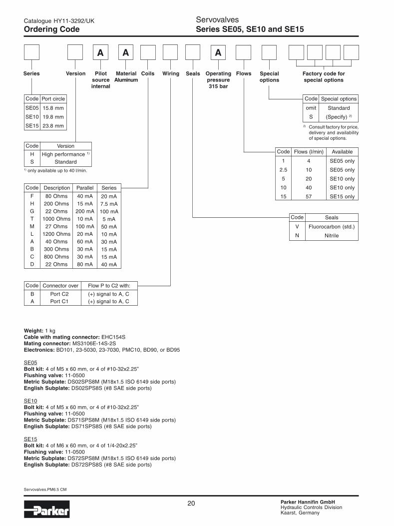
Ordering Code
Series
ServovalvesSeries SE05, SE10 and SE15
Code
SE05
SE10
SE15
Port circle
15.8 mm
19.8 mm
23.8 mm
Wiring Seals Specialoptions
Factory code forspecial options
Flows
Weight: 1 kgCable with mating connector: EHC154SMating connector: MS3106E-14S-2SElectronics: BD101, 23-5030, 23-7030, PMC10, BD90, or BD95
SE05Bolt kit: 4 of M5 x 60 mm, or 4 of #10-32x2.25”Flushing valve: 11-0500Metric Subplate: DS02SPS8M (M18x1.5 ISO 6149 side ports)English Subplate: DS02SPS8S (#8 SAE side ports)
SE10Bolt kit: 4 of M5 x 60 mm, or 4 of #10-32x2.25”Flushing valve: 11-0500Metric Subplate: DS71SPS8M (M18x1.5 ISO 6149 side ports)English Subplate: DS71SPS8S (#8 SAE side ports)
SE15Bolt kit: 4 of M6 x 60 mm, or 4 of 1/4-20x2.25”Flushing valve: 11-0500Metric Subplate: DS72SPS8M (M18x1.5 ISO 6149 side ports)English Subplate: DS72SPS8S (#8 SAE side ports)
Pilotsourceinternal
MaterialAluminum
Coils Operatingpressure315 bar
Code
FHGTMLABCD
Description Parallel
20 mA7.5 mA100 mA
5 mA50 mA10 mA30 mA15 mA15 mA40 mA
80 Ohms200 Ohms22 Ohms
1000 Ohms27 Ohms
1200 Ohms40 Ohms
300 Ohms800 Ohms22 Ohms
Series
40 mA15 mA
200 mA10 mA
100 mA20 mA60 mA30 mA30 mA80 mA
Code
1
2.5
5
10
15
Flows (l/min)
4
10
20
40
57
Code
HS
Version
High performance 1)
Standard
Code
V
N
Seals
Fluorocarbon (std.)
Nitrile
Code Connector over Flow P to C2 with:
B Port C2 (+) signal to A, CA Port C1 (+) signal to A, C
Code
omit
S
Special options
Standard
(Specify) 2)
2) Consult factory for price,delivery and availabilityof special options.
Version
AA A
Available
SE05 only
SE05 only
SE10 only
SE10 only
SE15 only
1) only available up to 40 l/min.

21
Servovalves.PM6.5 CM
Parker Hannifin GmbHHydraulic Controls DivisionKaarst, Germany
Catalogue HY11-3292/UK ServovalvesSeries SE05, SE10 and SE15Characteristics Curves
Dynamic response at 210 barstandard responseSE05: 4 - 20 l/min
high responseSE05: 4 - 20 l/min
Dynamic response at 210 barstandard responseSE10: 40 l/min
high responseSE10: 40 l/min
Dynamic response at 210 barstandard responseSE15: 60 l/min

22
Servovalves.PM6.5 CM
Parker Hannifin GmbHHydraulic Controls DivisionKaarst, Germany
Catalogue HY11-3292/UK
Characteristics Curves/WiringServovalvesSeries SE05, SE10 and SE15
Step response at 210 barstandard responseSE05/10/15: 4 - 40 l/min
high responseSE05: 20 l/min, SE10: 40 l/min
Installation Wiring Options
This servovalve has two coils. When connecting the valve to a drive amplifier, the user’s external wiring may put thecoils either in parallel or in series as needed. Refer to the illustrations below and to the mounting pattern for thisvalve to insure proper control phasing.
Polarity shown connects flow from P to C2 port.

23
Servovalves.PM6.5 CM
Parker Hannifin GmbHHydraulic Controls DivisionKaarst, Germany
Catalogue HY11-3292/UK
1. Suggested mounting bolts: For SE05 and SE10 useM5 x 60 mm long high tensile steel socket head capscrews. For SE15 use M6 x 60 mm long.
2. 4-way electrical connector mates with MS3106E-14S-2S or equivalent. Is available at 180° to position shown(advise desired position at time of order).
3. Base O-Rings:SE05 use Parker 2011V-9 (7.66 mm I/D x 1.78 section)SE10 use Parker 2012V-9 (9.25 mm I/D x 1.78 section)SE15 use Parker 2013V-9 (10.82 mm I/D x 1.78 section)
4. Null adjust requires 10 A/F ring spanner and 2.5 hexa-gon key. Flow out of C1 will increase with clockwiserotation of key.
5. See mounting dimensions for port size and locations.
DimensionsServovalvesSeries SE05, SE10 and SE15
24
Servovalves.PM6.5 CM
Parker Hannifin GmbHHydraulic Controls DivisionKaarst, Germany
Catalogue HY11-3292/UK
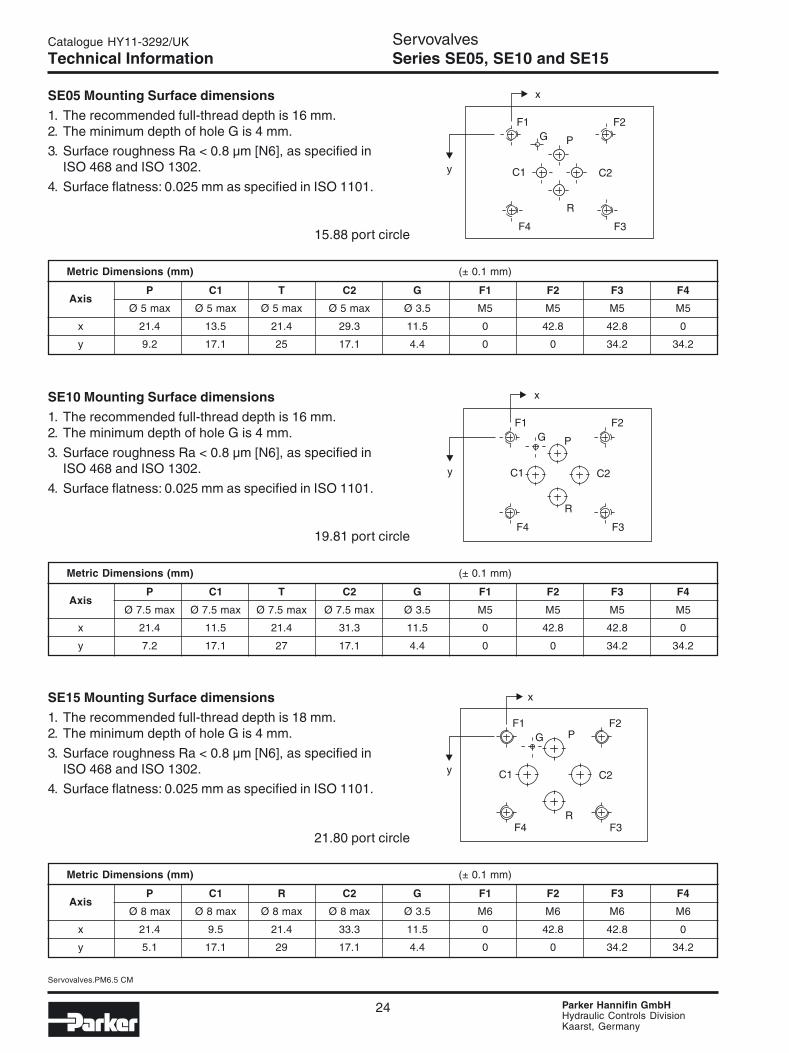
SE05 Mounting Surface dimensions
1. The recommended full-thread depth is 16 mm.2. The minimum depth of hole G is 4 mm.
3. Surface roughness Ra < 0.8 µm [N6], as specified inISO 468 and ISO 1302.
4. Surface flatness: 0.025 mm as specified in ISO 1101.
ServovalvesSeries SE05, SE10 and SE15Technical Information
Metric Dimensions (mm) (± 0.1 mm)
P C1 T C2 G F1 F2 F3 F4Axis
Ø 5 max Ø 5 max Ø 5 max Ø 5 max Ø 3.5 M5 M5 M5 M5
x 21.4 13.5 21.4 29.3 11.5 0 42.8 42.8 0
y 9.2 17.1 25 17.1 4.4 0 0 34.2 34.2
SE10 Mounting Surface dimensions
1. The recommended full-thread depth is 16 mm.2. The minimum depth of hole G is 4 mm.
3. Surface roughness Ra < 0.8 µm [N6], as specified inISO 468 and ISO 1302.
4. Surface flatness: 0.025 mm as specified in ISO 1101.
Metric Dimensions (mm) (± 0.1 mm)
P C1 T C2 G F1 F2 F3 F4Axis
Ø 7.5 max Ø 7.5 max Ø 7.5 max Ø 7.5 max Ø 3.5 M5 M5 M5 M5
x 21.4 11.5 21.4 31.3 11.5 0 42.8 42.8 0
y 7.2 17.1 27 17.1 4.4 0 0 34.2 34.2
SE15 Mounting Surface dimensions
1. The recommended full-thread depth is 18 mm.2. The minimum depth of hole G is 4 mm.
3. Surface roughness Ra < 0.8 µm [N6], as specified inISO 468 and ISO 1302.
4. Surface flatness: 0.025 mm as specified in ISO 1101.
Metric Dimensions (mm) (± 0.1 mm)
P C1 R C2 G F1 F2 F3 F4Axis
Ø 8 max Ø 8 max Ø 8 max Ø 8 max Ø 3.5 M6 M6 M6 M6
x 21.4 9.5 21.4 33.3 11.5 0 42.8 42.8 0
y 5.1 17.1 29 17.1 4.4 0 0 34.2 34.2
15.88 port circle
19.81 port circle
21.80 port circle
25
Servovalves.PM6.5 CM
Parker Hannifin GmbHHydraulic Controls DivisionKaarst, Germany
Catalogue HY11-3292/UK
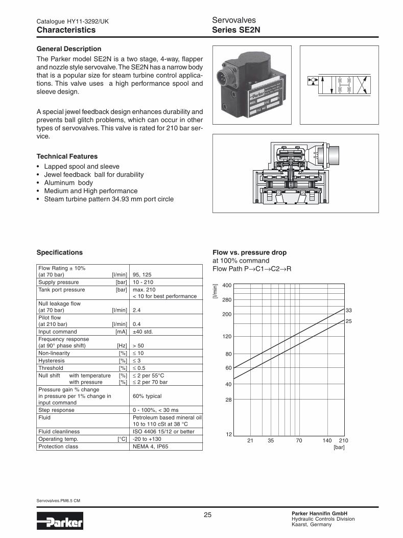
General Description
The Parker model SE2N is a two stage, 4-way, flapperand nozzle style servovalve. The SE2N has a narrow bodythat is a popular size for steam turbine control applica-tions. This valve uses a high performance spool andsleeve design.
A special jewel feedback design enhances durability andprevents ball glitch problems, which can occur in othertypes of servovalves. This valve is rated for 210 bar ser-vice.
Technical Features• Lapped spool and sleeve• Jewel feedback ball for durability• Aluminum body• Medium and High performance• Steam turbine pattern 34.93 mm port circle
Specifications
Flow Rating ± 10%(at 70 bar) [l/min] 95, 125Supply pressure [bar] 10 - 210Tank port pressure [bar] max. 210
< 10 for best performanceNull leakage flow(at 70 bar) [l/min] 2.4Pilot flow(at 210 bar) [l/min] 0.4Input command [mA] ±40 std.Frequency response(at 90° phase shift) [Hz] > 50Non-linearity [%] ≤ 10Hysteresis [%] ≤ 3Threshold [%] ≤ 0.5Null shift with temperature [%] ≤ 2 per 55°C
with pressure [%] ≤ 2 per 70 barPressure gain % changein pressure per 1% change in 60% typicalinput commandStep response 0 - 100%, < 30 msFluid Petroleum based mineral oil
10 to 110 cSt at 38 °CFluid cleanliness ISO 4406 15/12 or betterOperating temp. [°C] -20 to +130Protection class NEMA 4, IP65
CharacteristicsServovalvesSeries SE2N
Flow vs. pressure dropat 100% commandFlow Path P→C1→C2→R
26
Servovalves.PM6.5 CM
Parker Hannifin GmbHHydraulic Controls DivisionKaarst, Germany
Catalogue HY11-3292/UK
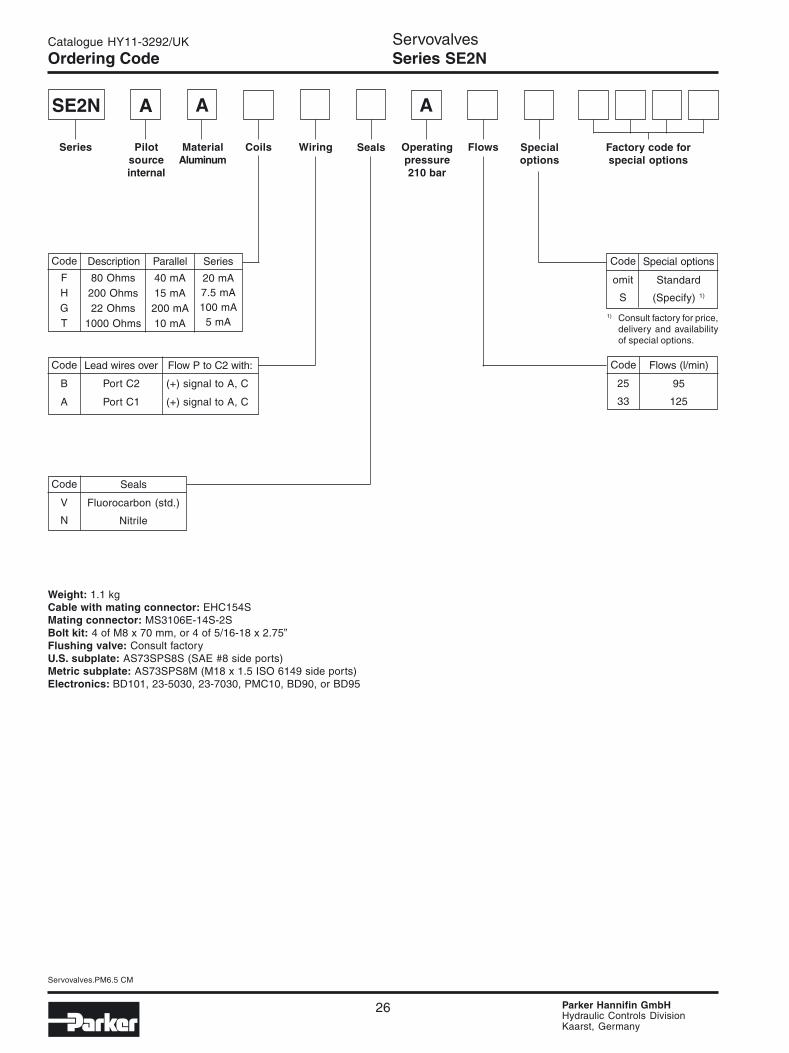
Ordering Code
SE2N A
Series Wiring Seals
A
Specialoptions
Factory code forspecial options
Flows
A
Code
omit
S
Special options
Standard
(Specify) 1)
Pilotsourceinternal
MaterialAluminum
Coils Operatingpressure210 bar
Code
FHGT
Description Parallel
20 mA7.5 mA100 mA
5 mA
80 Ohms200 Ohms22 Ohms
1000 Ohms
Series
40 mA15 mA200 mA10 mA
Code
B
A
Lead wires over Flow P to C2 with:
(+) signal to A, C
(+) signal to A, C
Port C2
Port C1
1) Consult factory for price,delivery and availabilityof special options.
Code
25
33
Flows (l/min)
95
125
Code
V
N
Seals
Fluorocarbon (std.)
Nitrile
ServovalvesSeries SE2N
Weight: 1.1 kgCable with mating connector: EHC154SMating connector: MS3106E-14S-2SBolt kit: 4 of M8 x 70 mm, or 4 of 5/16-18 x 2.75”Flushing valve: Consult factoryU.S. subplate: AS73SPS8S (SAE #8 side ports)Metric subplate: AS73SPS8M (M18 x 1.5 ISO 6149 side ports)Electronics: BD101, 23-5030, 23-7030, PMC10, BD90, or BD95

27
Servovalves.PM6.5 CM
Parker Hannifin GmbHHydraulic Controls DivisionKaarst, Germany
Catalogue HY11-3292/UK
Installation Wiring Options
This servovalve has two coils. When connecting the valve to a drive amplifier, the user’s external wiring may put thecoils either in parallel or in series as needed. Refer to the illustrations below and to the mounting pattern for thisvalve to insure proper control phasing.
Polarity shown connects flow from P to C2 port.
Characteristics Curves/WiringServovalvesSeries SE2N
Dynamic response at 210 barstandard response95 l/min
standard response95 l/min
Step response at 210 bar

28
Servovalves.PM6.5 CM
Parker Hannifin GmbHHydraulic Controls DivisionKaarst, Germany
Catalogue HY11-3292/UK
Metric Dimensions (mm) (± 0.1 mm)
P C1 R C2 F1 F2 F3 F4Axis
Ø 12.7 max Ø 12.7 max Ø 12.7 max Ø 12.7 max M10 M10 M10 M10
x 44.5 27 44.5 61.9 0 88.9 88.9 0
y 4.8 22.3 39.7 22.3 0 0 44.5 44.5
DimensionsServovalvesSeries SE2N
1. Suggested mounting bolts M8 x 70 mm long high ten-sile steel socket head cap screws.
2. The 4-way electrical connector mates with MS3106E-14S-2S or equivalent. Is available at 180° to positionshown (advise desired position at time of order).
3. Null adjust requires 2.5 hexagon key. Flow out of C2will increase with clockwise rotation of key.
4. Base O-Rings: 14.6 I/D x 2.4 section
Mounting Surface dimensions
1. The recommended full-thread depth is 22 mm.2. Surface roughness Ra < 0.8 µm [N6], as specified in
ISO 468 and ISO 1302.
3. Surface flatness: 0.025 mm as specified in ISO 1101.

29
Servovalves.PM6.5 CM
Parker Hannifin GmbHHydraulic Controls DivisionKaarst, Germany
Catalogue HY11-3292/UK
Specifications
Flow Rating ± 10%(at 70 bar) [l/min] 3.8, 9.5, 19, 38, 63, 75Supply pressure [bar] 10 - 315 (500 optional)Tank port pressure [bar] max. 210
< 10 for best performanceNull leakage flow(at 70 bar) [l/min] 1.2 - 1.9Pilot flow(at 210 bar) [l/min] 0.4 - 0.7Input command [mA] ±40 std.Frequency response(at 90° phase shift) [Hz] > 100Non-linearity [%] ≤ 10Hysteresis [%] ≤ 3Threshold [%] ≤ 0.5Null shift with temperature [%] ≤ 2 per 55°C
with pressure [%] ≤ 2 per 70 barPressure gain % changein pressure per 1% change in 60% typicalinput commandStep response see graphsFluid Petroleum based mineral oil
10 to 110 cSt at 38 °CFluid cleanliness ISO 4406 15/12 or betterOperating temp. [°C] -30 to +130Protection class NEMA 4, IP65
General Description
The Parker model SE20 is a two stage, 4-way, flapperand nozzle style servovalve. The SE20 has a wide rangeof flow ratings and a high performance spool and sleevedesign.
A special jewel feedback design enhances durability andprevents ball glitch problems, which can occur in othertypes of servovalves. This valve is rated for 315 bar ser-vice (option for 500 bar).
Technical Features• Lapped spool and sleeve• Jewel feedback ball for durability• Aluminum body• Medium and High performance• ISO 10372 standard 22.23 mm port circle
CharacteristicsServovalvesSeries SE20
Flow vs. pressure dropat 100% commandFlow Path P→C1→C2→R

30
Servovalves.PM6.5 CM
Parker Hannifin GmbHHydraulic Controls DivisionKaarst, Germany
Catalogue HY11-3292/UK
Ordering Code
SE20
Series Wiring Seals Specialoptions
Factory code forspecial options
Flows
Weight: 1 kgCable with mating connector: EHC154SBolt kit: 4 of M8 x 60 mm, or 4 of 5/16-18x2.25”Flushing valve: 1200127 (does not cover 5th port)U.S. Subplate, 5 ports: 1402303 (4) #12 SAE side ports, (1) #4 SAE side portsU.S. Subplate, 4 ports: 810090-3 (4) #12 SAE side portsMetric Subplate, 4 ports: DS04SPS12M (M27 x 2.0 ISO 6149 side ports)Electronics: BD101, 23-5030, 23-7030, PMC10, BD90, or BD95
Pilotsource
Materialoptions
Coils Operatingpressure
Code
FHGTMLABCD
Description Parallel
20 mA7.5 mA100 mA
5 mA50 mA10 mA30 mA15 mA15 mA40 mA
80 Ohms200 Ohms22 Ohms
1000 Ohms27 Ohms
1200 Ohms40 Ohms
300 Ohms800 Ohms22 Ohms
Series
40 mA15 mA
200 mA10 mA
100 mA20 mA60 mA30 mA30 mA80 mA
Code
1
2.5
5
10
16.5
20
Flows (l/min)
4
10
20
40
60
75
ServovalvesSeries SE20
Code
HS
Version
High performance 1)
Standard
Code
AC
Pilot source
internalexternal (5th port)
Code
AS
Material options
Aluminum (std.)Stainless Steel
Code
V
N
Seals
Fluorocarbon (std.)
Nitrile
Code Connector over Flow P to C2 with:
P Port P (+) signal to A, CB Port C2 (+) signal to A, CA Port C1 (+) signal to A, CT Port T (+) signal to A, C
Code
omit
S
Special options
Standard
(Specify) 2)
2) Consult factory for price,delivery and availabilityof special options
Code
AB
Operating pressure
315 bar500 bar 3)
3) Requires steel body
Version
1) only available up to 40 l/min
31
Servovalves.PM6.5 CM
Parker Hannifin GmbHHydraulic Controls DivisionKaarst, Germany
Catalogue HY11-3292/UK
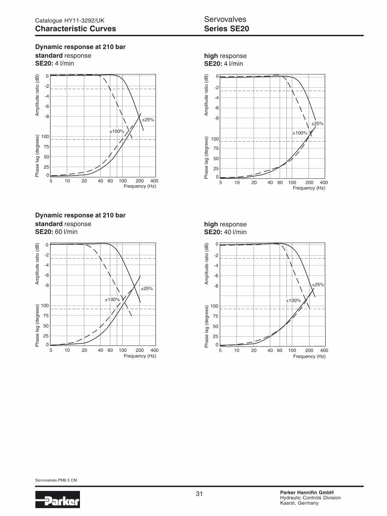
Characteristic CurvesServovalvesSeries SE20
Dynamic response at 210 barstandard responseSE20: 4 l/min
high responseSE20: 4 l/min
Dynamic response at 210 barstandard responseSE20: 60 l/min
high responseSE20: 40 l/min
32
Servovalves.PM6.5 CM
Parker Hannifin GmbHHydraulic Controls DivisionKaarst, Germany
Catalogue HY11-3292/UK
Characteristics Curves/WiringServovalvesSeries SE20
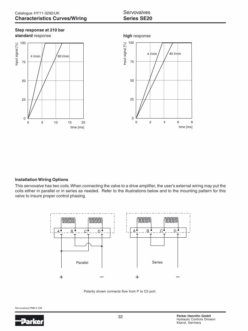
Installation Wiring Options
This servovalve has two coils. When connecting the valve to a drive amplifier, the user’s external wiring may put thecoils either in parallel or in series as needed. Refer to the illustrations below and to the mounting pattern for thisvalve to insure proper control phasing.
Polarity shown connects flow from P to C2 port.
Step response at 210 barstandard response high response

33
Servovalves.PM6.5 CM
Parker Hannifin GmbHHydraulic Controls DivisionKaarst, Germany
Catalogue HY11-3292/UK
Metric Dimensions (mm) (± 0.1 mm)
P C1 R C2 G X F1 F2 F3 F4Axis
Ø 8.2 max Ø 8.2 max Ø 8.2 max Ø 8.2 max Ø 3.5 Ø 5 M8 M8 M8 M8
x 22.2 11.1 22.2 33.3 12.3 33.3 0 44.4 44.4 0
y 21.4 32.5 43.6 32.5 19.8 8.7 0 0 65 65
Mounting Surface dimensions
1. The minimum depth of hole G is 2 mm.The ISO recommended full-thread depth is 22 mm.
2. Surface roughness Ra < 0.8 µm [N6], as specified inISO 468 and ISO 1302.
3. Surface flatness: 0.025 mm as specified in ISO 1101.
1. Suggested mounting bolts M8 x 60 mm high tensilesteel socket head cap screws.
2. The 4-way electrical connector mates with MS3106-14S-2S or equivalent. It is available at ±90° and 180°to position shown (advise desired position at time oforder).
3. Base O-Rings: 10.82 I/D x 1.78 section (2013N-9 or2013V-9) 5 pcs.
4. Null adjust requires 10 A/F ring spanner (10 mm box-end wrench) and 2.5 hexagon key. Flow out of C1 willincrease with clockwise rotation of key.
DimensionsServovalvesSeries SE20

34
Servovalves.PM6.5 CM
Parker Hannifin GmbHHydraulic Controls DivisionKaarst, Germany
Catalogue HY11-3292/UK
Notes

35
Servovalves.PM6.5 CM
Parker Hannifin GmbHHydraulic Controls DivisionKaarst, Germany
Catalogue HY11-3292/UK
Specifications
Flow Rating ± 10%(at 70 bar) [l/min] 3.8, 9.5, 19, 38, 60, 75Supply pressure [bar] 10 - 315Tank port pressure [bar] max. 210
< 10 for best performanceNull leakage flow(at 70 bar) [l/min] 1.2 - 1.9Pilot flow(at 210 bar) [l/min] 0.4 - 0.8Input command [V] ±10 std.Frequency response(at 90° phase shift) [Hz] ≤ 300Non-linearity [%] ≤ 5Hysteresis [%] ≤ 0.5Threshold [%] ≤ 0.1Null shift with temperature [%] ≤ 1 per 55°C
with pressure [%] ≤ 1 per 70 barPressure gain % changein pressure per 1% change in 80% typicalinput commandStep response 0 - 100%, 4 to 9 msFluid Petroleum based mineral oil
10 to 110 cSt at 38 °CFluid cleanliness ISO 4406 15/12 or betterOperating temp. [°C] -20 to +85Protection class NEMA 4, IP65
CharacteristicsServovalvesSeries SE2E
General Description
The Parker model SE2E features electronic spool posi-tion feedback and on-board electronics. Spool positionfeedback can be used as a safety monitoring tool, or forminimizing valve hysteresis. The SE2E is a two stage,4-way, flapper and nozzle style servovalve.
A special jewel feedback design enhances durability andprevents ball glitch problems, which can occur in othertypes of servovalves. This valve is rated for 315 bar ser-vice.
Technical Features• On-board electronics• Electronic spool position feedback• Jewel feedback ball for durability• High performance• ISO 10372 standard 22.23 mm port circle
Flow vs. pressure dropat 100% commandFlow Path P→C1→C2→R

36
Servovalves.PM6.5 CM
Parker Hannifin GmbHHydraulic Controls DivisionKaarst, Germany
Catalogue HY11-3292/UK
Ordering Code
SE2E
Series Wiring Seals Specialoptions
Factory code forspecial options
Flows
Code
omit
S
Special options
Standard
(Specify) 1)
Pilotsource
Materialoptions
Aluminum(std)
Command Operatingpressure315 bar
Code
1234
Commanddescription
Inputimpedance
± 10 volts± 10 mA± 10 volts± 10 mA
Re > 50 kOhmsRe > 1 kOhmsRe > 50 kOhmsRe > 1 kOhms
Code
P
B
A
T
Connector over Flow P to C2 with:
(+) signal to A, C
(+) signal to A, C
(+) signal to A, C
(+) signal to A, C
Port P
Port C2
Port C1
Port T
1) Consult factory for price,delivery and availabilityof special options.
Code
1
2.5
5
10
16.5
20
Flows (l/min)
4
10
20
40
60
75
Code
V
N
Seals
Fluorocarbon (std.)
Nitrile
ServovalvesSeries SE2E
Code
AC
Pilot source
internalexternal (5th port)
Weight: 1.5 kgCable with mating connector: EHC158GEMating connector: 5004072 (a 7-pin metal CE connector)Bolt kit: 4 of M8 x 60 mm, or 4 of 5/16-18x2.25”Flushing valve: 1200127 (does not cover 5th port)U.S. Subplate, 5 ports: 1402303 (4) #12 SAE side ports, (1) #4 SAE side portsU.S. Subplate, 4 ports: 810090-3 (4) #12 SAE side portsMetric Subplate, 4 ports: DS04SPS12M (M27 x 2.0 ISO 6149 side ports)Electronics: BD101, 23-5030, 23-7030, PMC10, BD90, or BD95
A A
Version
Code
HS
Version
High performanceStandard
Powersupply
± 15 volts DC power± 15 volts DC power24 volts DC power24 volts DC power
37
Servovalves.PM6.5 CM
Parker Hannifin GmbHHydraulic Controls DivisionKaarst, Germany
Catalogue HY11-3292/UK
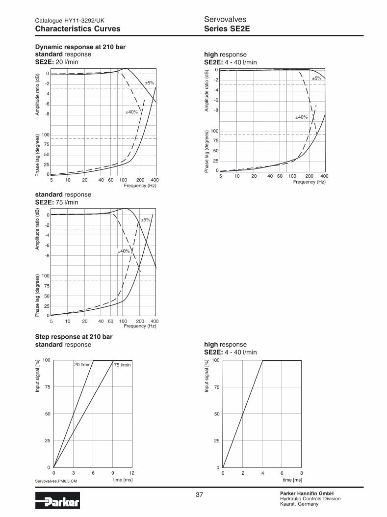
Characteristics CurvesServovalvesSeries SE2E
Dynamic response at 210 barstandard responseSE2E: 20 l/min
high responseSE2E: 4 - 40 l/min
standard responseSE2E: 75 l/min
standard response high responseSE2E: 4 - 40 l/min
Step response at 210 bar

38
Servovalves.PM6.5 CM
Parker Hannifin GmbHHydraulic Controls DivisionKaarst, Germany
Catalogue HY11-3292/UK
Mounting Surface dimensions
1. The minimum depth of hole G is 2 mm.The ISO recommended full-thread depth is 22 mm.
2. Surface roughness Ra < 0.8 µm [N6], as specified inISO 468 and ISO 1302.
3. Surface flatness: 0.025 mm as specified in ISO 1101.
Dimensions/WiringServovalvesSeries SE2E
Metric Dimensions (mm) (± 0.1 mm)
P C1 R C2 G X F1 F2 F3 F4Axis
Ø 8.2 max Ø 8.2 max Ø 8.2 max Ø 8.2 max Ø 3.5 Ø 5 M8 M8 M8 M8
x 22.2 11.1 22.2 33.3 12.3 33.3 0 44.4 44.4 0
y 21.4 32.5 43.6 32.5 19.8 8.7 0 0 65 65
1. Suggested mounting bolts M8 x 60 mm long high ten-sile steel socket head cap screws.
2. The 7-pin electrical connector mates with Parker5004072 connector or equivalent. The connector isavailable at 180° to position shown (advise desiredposition at time of order).
3. Base O-Rings: 10.82 I/D x 1.78 section (2013N-9 or2013V-9) 5 pcs.
4. Null adjustment potentiometer.
39
Servovalves.PM6.5 CM
Parker Hannifin GmbHHydraulic Controls DivisionKaarst, Germany
Catalogue HY11-3292/UK
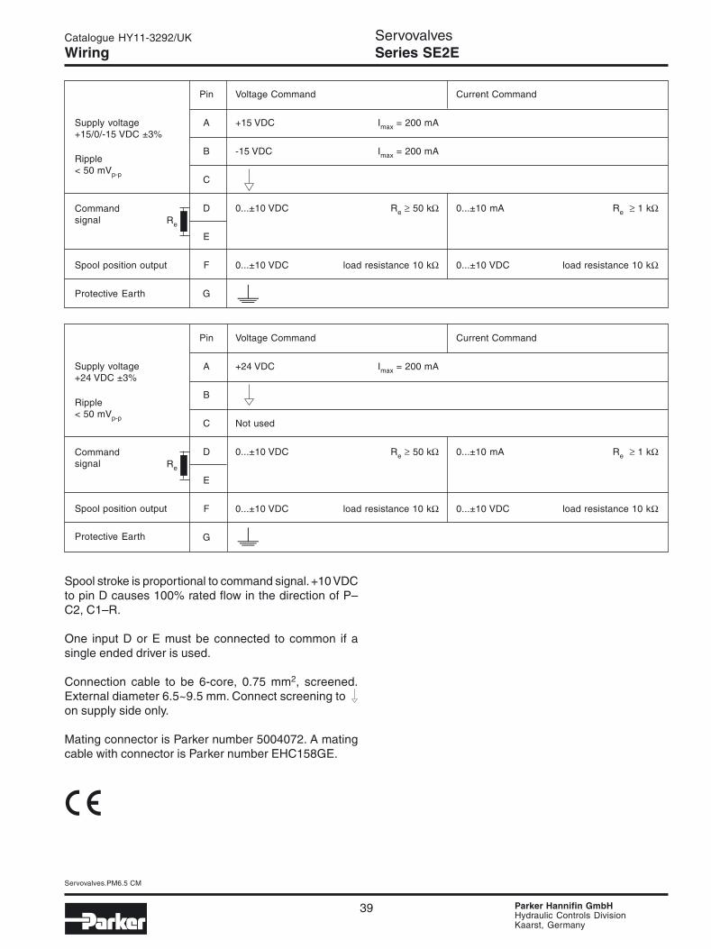
WiringServovalvesSeries SE2E
Supply voltage+15/0/-15 VDC ±3%
Ripple< 50 mVp-p
Commandsignal
Spool position output
Pin Voltage Command Current Command
A +15 VDC Imax = 200 mA
B -15 VDC Imax = 200 mA
C
D 0...±10 VDC Re ≥ 50 kΩ 0...±10 mA Re ≥ 1 kΩ
E
F 0...±10 VDC load resistance 10 kΩ 0...±10 VDC load resistance 10 kΩ
G
Re
Supply voltage+24 VDC ±3%
Ripple< 50 mVp-p
Commandsignal
Spool position output
Pin Voltage Command Current Command
A +24 VDC Imax = 200 mA
B
C Not used
D 0...±10 VDC Re ≥ 50 kΩ 0...±10 mA Re ≥ 1 kΩ
E
F 0...±10 VDC load resistance 10 kΩ 0...±10 VDC load resistance 10 kΩ
G
Re
Spool stroke is proportional to command signal. +10 VDCto pin D causes 100% rated flow in the direction of P–C2, C1–R.
One input D or E must be connected to common if asingle ended driver is used.
Connection cable to be 6-core, 0.75 mm2, screened.External diameter 6.5~9.5 mm. Connect screening toon supply side only.
Mating connector is Parker number 5004072. A matingcable with connector is Parker number EHC158GE.
Protective Earth
Protective Earth

40
Servovalves.PM6.5 CM
Parker Hannifin GmbHHydraulic Controls DivisionKaarst, Germany
Catalogue HY11-3292/UK
Notes

41
Servovalves.PM6.5 CM
Parker Hannifin GmbHHydraulic Controls DivisionKaarst, Germany
Catalogue HY11-3292/UK
Specifications
Flow Rating ± 10%(at 70 bar) [l/min] 10, 20, 40, 60Supply pressure [bar] 10 - 315Tank port pressure [bar] max. 210
< 10 for best performanceNull leakage flow(at 70 bar) [l/min] 1.2 - 1.9Pilot flow(at 210 bar) [l/min] 0.4 - 0.7Input command [mA] ±100 std.Frequency response(at 90° phase shift) [Hz] > 100Non-linearity [%] ≤ 10Hysteresis [%] ≤ 3Threshold [%] ≤ 0.5Null shift with temperature [%] ≤ 2 per 55°C
with pressure [%] ≤ 2 per 70 barPressure gain % changein pressure per 1% change in 60% typicalinput commandStep response 0 - 100%, < 15 msFluid Petroleum based mineral oil
10 to 110 cSt at 38 °CFluid cleanliness ISO 4406 15/12 or betterOperating temp. [°C] -30 to +130Protection class NEMA 4, IP65
CharacteristicsServovalvesSeries SE31
General Description
The Parker model SE31 is a two stage, 4-way, flapperand nozzle style servovalve. This valve is designed to fitonto DIN NG10 or NFPA D05 port patterns. The SE31has a wide range of flow ratings and a high performancespool and sleeve design.
A special jewel feedback design enhances durability andprevents ball glitch problems, which can occur in othertypes of servovalves. This valve is rated for 315 bar ser-vice.
Technical Features• Lapped spool and sleeve• Jewel feedback ball for durability• Aluminum body• Medium and High performance• ISO 440 -05-05-0-94 (4-ports), DO5HE (no “Y” port)
Flow vs. pressure dropat 100% commandFlow Path P→C1→C2→R

42
Servovalves.PM6.5 CM
Parker Hannifin GmbHHydraulic Controls DivisionKaarst, Germany
Catalogue HY11-3292/UK
Ordering Code
SE31
Series Wiring Seals Specialoptions
Factory code forspecial options
FlowsPilotsource
Materialoption
Aluminum
Coils Operatingpressure
ServovalvesSeries SE31
Weight: 1.1 kgCable with mating connector: EHC154SMating connector: MS3106E-14S-2SBolt kit: 4 of M6 x 50 mm, or 4 of 1/4-20x2.00”Flushing valve: D3L8CVSubplate, 5 ports: D31D6SA35 (4 side ports #12 SAE, 1 pilot port on P side is #4 SAE)Subplate, 4 ports: D3H6SA35 (4 side ports #12 SAE)Electronics: BD101, 23-5030, 23-7030, PMC10, BD90, or BD95
Code
omit
S
Special options
Standard
(Specify) 2)
2) Consult factory for price,delivery and availabilityof special options.
Code
MBFHGTCLAD
Description Parallel
50 mA15 mA20 mA7.5 mA100 mA
5 mA15 mA10 mA30 mA40 mA
27 Ohms300 Ohms80 Ohms
200 Ohms22 Ohms
1000 Ohms800 Ohms
1200 Ohms40 Ohms22 Ohms
Series
100 mA30 mA40 mA15 mA
200 mA10 mA30 mA20 mA60 mA80 mA
Code
2.5
5
10
15
Flows (l/min)
10
20
40
60
Code
HS
Version
High performance 1)
Standard
Code
V
N
Seals
Fluorocarbon (std.)
Nitrile
Version
Code
AC
Pilot source
internalexternal (5th port)
Code Connector over Flow P to C2 with:
B Port C2 (+) signal to A, CA Port C1 (+) signal to A, C
Code
AB
Operating pressure
210 bar315 bar
A
1) only available up to 40 l/min.

43
Servovalves.PM6.5 CM
Parker Hannifin GmbHHydraulic Controls DivisionKaarst, Germany
Catalogue HY11-3292/UK ServovalvesSeries SE31Characteristics Curves
Dynamic response at 210 barstandard responseSE31: 4 l/min
high responseSE31: 4 l/min
Dynamic response at 210 barstandard responseSE31: 60 l/min
high responseSE31: 40 l/min

44
Servovalves.PM6.5 CM
Parker Hannifin GmbHHydraulic Controls DivisionKaarst, Germany
Catalogue HY11-3292/UK
Installation Wiring Options
This servovalve has two coils. When connecting the valve to a drive amplifier, the user’s external wiring may put thecoils either in parallel or in series as needed. Refer to the illustrations below and to the mounting pattern for thisvalve to insure proper control phasing.
Polarity shown connects flow from P to C2 port.
Characteristics Curves/WiringServovalvesSeries SE31
Step response at 210 barstandard response high response
45
Servovalves.PM6.5 CM
Parker Hannifin GmbHHydraulic Controls DivisionKaarst, Germany
Catalogue HY11-3292/UK
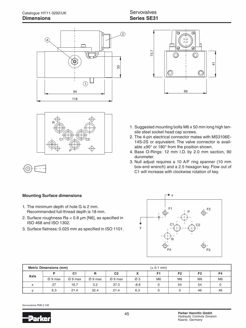
DimensionsServovalvesSeries SE31
Metric Dimensions (mm) (± 0.1 mm)
P C1 R C2 X F1 F2 F3 F4Axis
Ø 9 max Ø 9 max Ø 9 max Ø 9 max Ø 3 M6 M6 M6 M6
x 27 16.7 3.2 37.3 -8.8 0 54 54 0
y 6.3 21.4 32.4 21.4 6.3 0 0 46 46
1. Suggested mounting bolts M6 x 50 mm long high ten-sile steel socket head cap screws.
2. The 4-pin electrical connector mates with MS3106E-14S-2S or equivalent. The valve connector is avail-able ±90° or 180° from the position shown.
4. Base O-Rings: 12 mm I.D. by 2.0 mm section, 90durometer.
3. Null adjust requires a 10 A/F ring spanner (10 mmbox-end wrench) and a 2.5 hexagon key. Flow out ofC1 will increase with clockwise rotation of key.
Mounting Surface dimensions
1. The minimum depth of hole G is 2 mm.Recommended full-thread depth is 18 mm.
2. Surface roughness Ra < 0.8 µm [N6], as specified inISO 468 and ISO 1302.
3. Surface flatness: 0.025 mm as specified in ISO 1101.

46
Servovalves.PM6.5 CM
Parker Hannifin GmbHHydraulic Controls DivisionKaarst, Germany
Catalogue HY11-3292/UK
Notes

47
Servovalves.PM6.5 CM
Parker Hannifin GmbHHydraulic Controls DivisionKaarst, Germany
Catalogue HY11-3292/UK
Specifications
Flow Rating ± 10%(at 70 bar) [l/min] 95, 150, 230Supply pressure [bar] 10 - 210Tank port pressure [bar] max. 210
< 10 for best performanceNull leakage flow(at 70 bar) [l/min] 2.4 - 3.6Pilot flow(at 210 bar) [l/min] 0.4Input command [mA] ±40 std.Frequency response(at 90° phase shift) [Hz] > 100Non-linearity [%] ≤ 10Hysteresis [%] ≤ 4Threshold [%] ≤ 1Null shift with temperature [%] ≤ 2 per 55°C
with pressure [%] ≤ 2 per 70 barPressure gain % changein pressure per 1% change in 60% typicalinput commandStep response 0 - 100%, < 15 msFluid Petroleum based mineral oil
10 to 110 cSt at 38 °CFluid cleanliness ISO 4406 15/12 or betterOperating Temp. [°C] -30 to +130Protection class NEMA 4, IP65
CharacteristicsServovalvesSeries SE60
General Description
The Parker model SE60 is a two stage, 4-way, flapperand nozzle style servovalve. The SE60 has a wide rangeof flow ratings and a high performance spool and sleevedesign.
A special jewel feedback design enhances durability andprevents ball glitch problems, which can occur in othertypes of servovalves. This valve is rated for 210 bar ser-vice.
Technical Features• Lapped spool and sleeve• Jewel feedback ball for durability• Aluminum body• Medium and High performance• ISO 10372 size 6 standard 50.8 mm port circle
Flow vs. pressure dropat 100% commandFlow Path P→C1→C2→R

48
Servovalves.PM6.5 CM
Parker Hannifin GmbHHydraulic Controls DivisionKaarst, Germany
Catalogue HY11-3292/UK
Ordering Code
SE60
Series Wiring Seals Specialoptions
Factory code forspecial options
FlowsPilotsource
MaterialAluminum
Coils Operatingpressure210 bar
ServovalvesSeries SE60
Weight: 3.4 kgCable with mating connector: EHC154SMating connector: MS3106E-14S-2SBolt kit: 4 of M10 x 60 mm, or 4 of 3/8-16x2.375”Flushing valve: Consult factory.US Subplate, 4 ports: AS06SPS20S (# 20 SAE side ports)Metric Subplate, 4 ports: AS06SPS20M (M42 x 2.0 ISO 6149 side ports)Electronics: BD101, 23-5030, 23-7030, PMC10, BD90, or BD95
Code
25
40
60
Flows (l/min)
95
150
230
Code
HS
Version
High performance 1)
Standard
Code
V
N
Seals
Fluorocarbon (std.)
Nitrile
Version
Code
AC
Pilot source
internalexternal
Code Connector over Flow P to C2 with:
B Port C2 (+) signal to A, CA Port C1 (+) signal to A, C
A
Code
FHGTMLABCD
Description Parallel
20 mA7.5 mA100 mA
5 mA50 mA10 mA30 mA15 mA15 mA40 mA
80 Ohms200 Ohms22 Ohms
1000 Ohms27 Ohms
1200 Ohms40 Ohms
300 Ohms800 Ohms22 Ohms
Series
40 mA15 mA
200 mA10 mA
100 mA20 mA60 mA30 mA30 mA80 mA
A
Code
omit
F
S
Special options
Standard
Field replaceablefilter
(Specify) 2)
2) Consult factory for price, deliv-ery and availability of specialoptions.
1) Consult factory for price, de-livery and availability of highperformance version.

49
Servovalves.PM6.5 CM
Parker Hannifin GmbHHydraulic Controls DivisionKaarst, Germany
Catalogue HY11-3292/UK ServovalvesSeries SE60
Installation Wiring Options
This servovalve has two coils. When connecting the valve to a drive amplifier, the user’s external wiring may put thecoils either inparallel or in series as needed. Refer to the illustrations below and to the mounting pattern for this valveto insure proper control phasing.
Polarity shown connects flow from P to C2 port.
Characteristics Curves/Wiring
Dynamic response at 210 barstandard responseSE60: 95 l/min SE60: 230 l/min
Step response at 210 barstandard response
50
Servovalves.PM6.5 CM
Parker Hannifin GmbHHydraulic Controls DivisionKaarst, Germany
Catalogue HY11-3292/UK
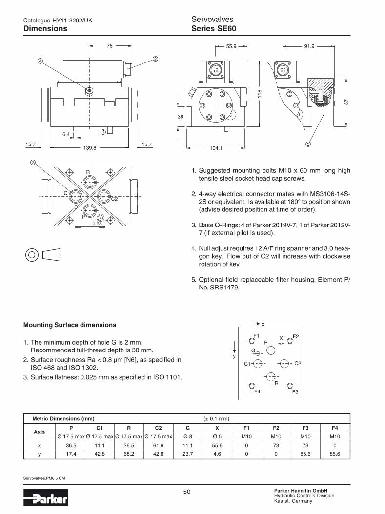
DimensionsServovalvesSeries SE60
1. Suggested mounting bolts M10 x 60 mm long hightensile steel socket head cap screws.
2. 4-way electrical connector mates with MS3106-14S-2S or equivalent. Is available at 180° to position shown(advise desired position at time of order).
3. Base O-Rings: 4 of Parker 2019V-7, 1 of Parker 2012V-7 (if external pilot is used).
4. Null adjust requires 12 A/F ring spanner and 3.0 hexa-gon key. Flow out of C2 will increase with clockwiserotation of key.
5. Optional field replaceable filter housing. Element P/No. SRS1479.
Metric Dimensions (mm) (± 0.1 mm)
P C1 R C2 G X F1 F2 F3 F4Axis
Ø 17.5 max Ø 17.5 max Ø 17.5 max Ø 17.5 max Ø 8 Ø 5 M10 M10 M10 M10
x 36.5 11.1 36.5 61.9 11.1 55.6 0 73 73 0
y 17.4 42.8 68.2 42.8 23.7 4.6 0 0 85.6 85.6
Mounting Surface dimensions
1. The minimum depth of hole G is 2 mm.Recommended full-thread depth is 30 mm.
2. Surface roughness Ra < 0.8 µm [N6], as specified inISO 468 and ISO 1302.
3. Surface flatness: 0.025 mm as specified in ISO 1101.
51
Servovalves.PM6.5 CM
Parker Hannifin GmbHHydraulic Controls DivisionKaarst, Germany
Catalogue HY11-3292/UK
Notes

Parker Hannifin is the world’s premier supplier of motion and control systemsand solutions, with sales and manufacturing facilities throughout the world. Forproduct information and details of your nearest Parker sales office, visit us atwww.parker.com or call free on 00800 2727 5374.
Hydraulics GroupSales Offices
AustriaWiener NeustadtTel: +43 (0)2622 23501Fax: +43 (0)2622 66212
BelgiumNivellesParc Industriel Sud-Zone IITel: +32 (0)67 280 900Fax: +32 (0)67 280 999
Czech RepublicPragueTel: +420 2 830 85 221Fax: +420 2 830 85 360
DenmarkIshøjTel: +45 4356 0400Fax: +45 4373 8431
FinlandVantaaTel: +358 (0)9 4767 31Fax: +358 (0)9 4767 3200
FranceContamine-sur-ArveTel: +33 (0)450 25 80 25Fax: +33 (0)450 03 67 37
GermanyKaarstTel: +49 (0)2131 4016 0Fax: +49 (0)2131 4016 9199
HungaryBudapestTel: +36 (06)1 220 4155Fax: +36 (06)1 422 1525
IrelandCloneeTel: +353 (0)1 801 4010Fax: +353 (0)1 801 4132
ItalyCorsico (MI)Tel: +39 02 45 19 21Fax: +39 02 4 47 93 40
The NetherlandsOldenzaalTel: +31 (0)541 585000Fax: +31 (0)541 585459
NorwaySkiTel: +47 64 91 10 00Fax: +47 64 91 10 90
PolandWarsawTel: +48 (0)22 863 49 42Fax: +48 (0)22 863 49 44
PortugalLeca da PalmeiraTel: +351 22 9997 360Fax: +351 22 9961 527
SlovakiaRef. Czech Republic
SpainMadridTel: +34 91 675 73 00Fax: +34 91 675 77 11
SwedenSpångaTel: +46 (0)8 597 950 00Fax: +46 (0)8 597 951 10
United KingdomWatford (industrial)Tel: +44 (0)1923 492 000Fax: +44 (0)1923 256 059Ossett (mobile)Tel: +44 (0)1924 282 200Fax: +44 (0)1924 282 299
InternationalEurope
Catalogue HY11-3292/UK11/03 LIM
© Copyright 2003Parker Hannifin CorporationAll rights reserved.
AustraliaCastle HillTel: +61 (0)2-9634 7777Fax: +61 (0)2-9899 6184
CanadaMilton, OntarioTel: +1 905-693-3000Fax: +1 905-876-0788
ChinaBeijingTel: +86 10 6561 0520Fax: +86 10 6561 0526
Asia Pacific GroupHong Kong, KowloonTel: +852 2428 8008Fax: +852 2425 6896
IndiaMumbaiTel: +91 22 7907081Fax: +91 22 7907080
JapanTokyoTel: +(81) 3 6408 3900Fax: +(81) 3 5449 7201
Latin America GroupBrazilTel: +55 12 3954-5100Fax: +55 12 3954-5266
South AfricaKempton ParkTel: +27 (0)11-961 0700Fax: +27 (0)11-392 7213
USACleveland (industrial)Tel: +1 216-896-3000Fax: +1 216-896-4031Lincolnshire (mobile)Tel: +1 847-821-1500Fax: +1 847-821-7600